

Page 1
PAC-1000G
6-slot Wall-mount Chassis
Version: 1.0
Quick Installation Guide
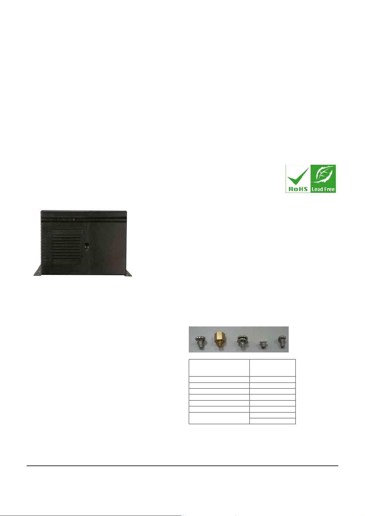
ABOUT THE PAC-1000G
The 6-slot, heavy-duty steel PAC-1000G AT/ATX compact
wall-mount industrial chassis is designed to operate reliably in
industrial environments where it will be exposed to dust, wide
temperature variations, and shocks and vibrations, among other
things.
SPECIFICATIONS
Form Factor: 6-slot compact chassis
SBC Form Factor: Full-size, slot CPU cards
Construction: Plastic
Slots Number: 6-slot
Cooling: 1 x 8cm fan
Drive Bays:
o 1 x 5.25” Front accessible Optical drive bay
o 1 x 3.5” Front accessible FDD (floppy disk drive) or
HDD (hard disk drive)
o 1 x 3.5” Internal HDD (hard disk drive) drive bay
Dimensions (DxWxH):
o 421mm x 232mm x 176mm
Operating Temperature: 0~40°C
Relative Humidity: 5~95%
Vibration:
o 5 to 17Hz, 0.1” double amplitude displacement
o 17 to 640Hz, 1.5G acceleration peak to peak
Shock: 10G acceleration peak to peak
PACKING LIST
When you unpack the chassis, make sure the following items
have been shipped.
1 x Quick Installation Guide
1 x Power cord
2 x Wall-mount plates
3 x Long PCI/ISA card shock absorbers
3 x Short PCI/ISA card shock absorbers
1 x Screw set
2 x Clip nuts
DETAILS OF INCLUDED SCREWS
The attached screw set includes 5 types of screws. Screws
used for chassis installation are shown below.
1 2 3 4 5
Peripherals/Parts
5.25” Optical Drives 5
3.5” FDD 5
3.5” HDD 1
2.5” HDD 4
Power Supply Unit 1
Wall-mount Bracket 3
Table 1: Screws for Peripheral/Parts
Screw Label (refer
to the picture
above)
3 Backplane
2
PAC-1000G QIG IEI Technology Corp. Page 1
Page 2
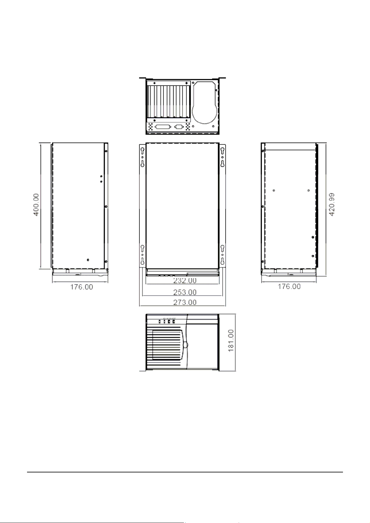
DIMENSION DRAWING
The dimensions of PAC-1000G are shown below.
Figure 1: Dimension Drawing (measurement units: millimeter)
PAC-1000G QIG IEI Technology Corp. Page 2
Page 3
INSTALLATION STEPS
To install the PAC-1000G chassis, the following installation steps
must be completed:
Step 1: Unpack the chassis.
Step 2: Remove the top cover and hold-down clamp.
Step 3: Install the PSU.
Step 4: Install the backplane.
Step 5: Install the CPU card.
Step 6: Install the PCI and ISA expansion cards.
Step 7: Install the disk drives.
Step 8: Connect the cables.
Step 9: Connect the PSU cable and the interface cable.
Step 10: Reinstall the hold-down clamp, shock absorbers
and top cover.
Step 11: Install the wall-mount plates.Step 0:
The installation steps outlined above are described in detail below.
Please refer to the relevant section.
STEP 1: UNPACK
The PAC-1000G is shipped in a plastic bag that is placed inside a
cardboard box. The items are also shipped with the chassis. When
you unpack the chassis you must:
Make sure all the items listed in the PACKING LIST
section are present.
Make sure the chassis has not been damaged in any
way.
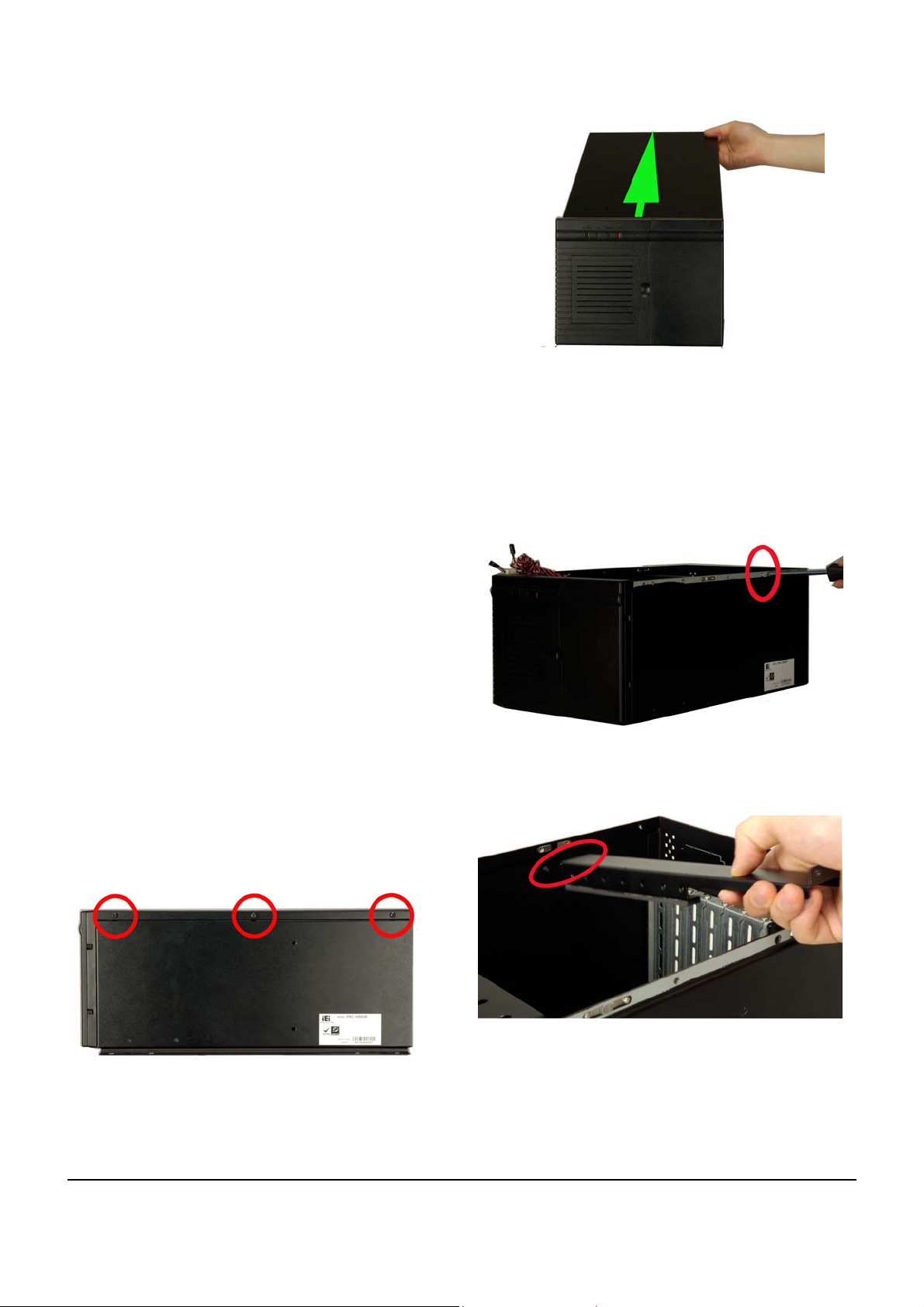
STEP 2: REMOVE THE TOP COVER AND
HOLD-DOWN CLAMP
STEP 2.1: REMOVE THE TOP COVER
The top cover is secured to the chassis with 6 retention
screws, 3 on each side of the chassis.
Figure 3: Remove the Top Cover
TEP 2.2: HOLD-DOWN CLAMP REMOVAL
S
Detach the hold-down clamp by removing the two screws
located on the right side of the chassis and pull the hold-down
clamp out of the two securing pillars on the left side of the
chassis.
Figure 4: Remove Two Hold-Down Clamp Side
Retention Screws
Step 1: Remove all six top cover retention screws.
Remove three retention screws from each side of
the chassis.
Figure 5: Two Hold-Down Clamp Securing Pillars
Figure 2: Remove Top Cover Retention Screws
Step 2: Slide the cover backwards and then lift the cover
up gently.Step 0:
PAC-1000G QIG IEI Technology Corp. Page 3
Page 4

STEP 3: INSTALL THE POWER SUPPLY UNIT (PSU)
Once the top cover and hold-down clamp have been removed, the PSU must be installed. Compatible IEI PSUs are listed in the table below.
Model No. Input Type Watt
+3.3V +5V +12V1 +12V2 -5V -12V +5Vsb
Output Range
ACE-832AP-RS
ACE-841AP-S-RS
ACE-850AP-RS
Table 2: Compatible IEI PSUs.
The PSU is installed at the rear of the chassis and secured to the
chassis with six retention screws, four retention screws at the
rear of the chassis and two on the right side of the chassis. To
install the PSU, please follow the steps below.
Step 1: Slide the two clip nuts onto the two clips on the
cable side of the PSU.
AC ATX 300W 28A 30A 15A N/A 0.3A 0.8A 2A
AC ATX 400W 28A 33A 20A N/A 0.5A 1A 2A
AC ATX 500W 27A 29A 18A 18A 0.3A 0.8A 2A
STEP 4: Backplane Installation
The IEI backplanes listed below are compatible with the
PAC-1000G chassis.
Model No. SBC Type PCI ISA PSU
BP-6S-RS-R30 ISA 0 6 AT
IP-6S-RS-R30 PCISA 3 2 AT
IP-6SA-RS-R30 PCISA 3 2 ATX
PCI-6S-RS-R30 PICMG 1.0 4 2 ATX/AT
Tabel 1: Compatible Backplane Modules
To install a backplane, please follow the instructions below:
Step 1: Insert six copper pillars into the six predrilled elevated
screw holes in the base of the chassis.
Figure 6: Slide Two Clip nuts onto the Two Clips of PSU
Step 2: Correctly position the PSU at the rear of the
chassis. Make sure the power switch and the
cable socket both face outwards.
Step 3: Secure the PSU to the rear of the chassis. To do
this, insert four retention screws from the rear of
the chassis and two retention screws from the
right side of the chassis. Step 0:
Figure 7: Six PSU Retention Screws
Figure 8: Six Copper Pillars
Step 2: Mount the backplane onto the copper pillars and the
three predrilled elevated retention screw holes. Make
sure the backplane screw holes are aligned with the
screw holes in the copper pillar and the predrilled
retention screw holes.
PAC-1000G QIG IEI Technology Corp. Page 4
Page 5

Figure 9: Three Predrilled Elevated Retention Screw Holes
Step 3: Secure the backplane to the base of the chassis with
nine retention screws.
Figure 10: Insert the Nine Backplane Retention Screws
STEP 5: CPU CARD INSTALLATION
To install the CPU card please follow the instructions below:
Step 1: Remove the slot cover at the back of the chassis.
To do this, remove the slot cover retention screw
at the top of the slot cover.
Figure 12: Full-size CPU Card Sockets
Step 3: To secure the CPU card, reinsert the previously
removed slot cover retention screw.Step 0:
STEP 6: PCI/ISA EXPANSION CARD
INSTALLATION
The PAC-1000G supports up to five PCI/ISA expansion
cards. If you wish to install a PCI expansion card or an ISA
expansion card please follow the instructions below:
Step 1: Remove the slot cover at the back of the chassis.
To do this, remove the slot cover retention screw
at the top of the slot cover.
Step 2: Slide the PCI/ISA expansion card into reserved
PCI/ISA socket on the backplane.
Figure 11: Remove the Slot Cover Retention Screw
Step 2: Slide a full-size CPU card into the socket on the
backplane reserved for the CPU card. Make sure
the back edge of the CPU card slots into the
corresponding card guide located behind the
cooling fans.
Figure 13: PCI and ISA Sockets
Step 3: To secure the PCI/ISA expansion card, reinsert
the previously removed slot cover retention
screw.Step 0:
STEP 7: DISK DRIVES INSTALLATION
The PAC-1000G chassis has the capacity for one
front-accessible 5.25” optical drive, one front accessible 3.5”
FDD and one internal 3.5” HDD.
To install the drives please follow the steps outlined in the
sections below.
PAC-1000G QIG IEI Technology Corp. Page 5
Page 6

TEP 7.1: DRIVE BRACKET REMOVAL
S
To remove the drive bracket, please follow the steps below:
Step 1: Remove the four drive bracket retention screws from the
right side of the chassis.
Figure 14: Four Side Drive Bracket Retention Screws
Step 2: Remove the one internal drive bracket retention screw
from the top of the fan bracket.
Figure 16: Secure an HDD to the Right Side of the Drive
Bracket
STEP 7.3: FDD/HDD INSTALLATION
To install a 3.5” FDD/HDD into the 3.5” front accessible drive
bracket, please follow the steps below:
Step 1: Slide a 3.5” FDD/HDD into the 3.5” FDD drive bay.
Make sure both the 4-pin power connector and
the IDE/SATA connector are at the rear of the
drive bracket.
Step 2: Align the retention screw holes in the 3.5”
FDD/HDD drive with the retention screw holes in
the 3.5” front accessible drive bay.
Step 3: Insert four retention screws, two on each side to
secure the 3.5” FDD/HDD to the drive bracket.
Figure 15: Internal Drive Bracket Retention Screw
TEP 7.2: INTERNAL HDD INSTALLATION
S
The PAC-1000G can support an HDD to be installed on the
right side of the drive bracket. To install a 3.5” HDD into the
right side of the drive bracket, please follow the steps below.
Step 1: Remove the drive bracket. To do this, please
STEP 8.1: DRIVE BRACKET REMOVAL.
refer to
Step 2: Slide a 3.5” HDD into the 3.5” drive bay. Make
sure both the 4-pin power connector and the
IDE/SATA connecter are at the rear of the drive
bracket.
Step 3: To secure the 3.5” drive to the drive bracket,
insert four retention screws, two on each side.
Step 0:
Figure 17:
Secure a 3.5"FDD to the 3.5"Drive Bay
STEP 7.4: OPTICAL DRIVE INSTALLATION
To install a 5.25” drive into the drive bracket, please follow
the steps below.
Step 1: Remove the drive bracket. To do this, please
refer to S
Step 2: Slide a 5.25” optical drive into the 5.25” drive bay
making sure both the 4-pin power connector and
the IDE/SATA connector are at the rear of the
drive bracket.
Step 3: Insert four retention screws, two on each side of
the drive bay to secure the 5.25” optical drive.
Step 0:
TEP 8.1: DRIVE BRACKET REMOVAL.
PAC-1000G QIG IEI Technology Corp. Page 6
Page 7

Figure 18: Secure a 5.25"Optical Drive to the 5.25"Drive Bay
STEP 7.5: DRIVE BRACKET REINSTALLATION
After the disk drives have been properly installed into the drive
brackets, reinstall the drive brackets into the chassis. To reinstall the
drive brackets into the chassis please follow the steps below:
Step 1: Remove the two plastic drive bay front covers
from the front of the drive bays by pushing the
plastic front covers out of the chassis.
o 1 x Power switch
o 1 x Reset button
These components are all connected to the CPU card with
cables. To correctly connect these cables, please refer to
the technical documentation that came with your CPU card.
The connectors that are provided with the chassis are listed
below.
No. Name
1
Power LED cable
1
Reset Switch cable
1
HDD LED cable
1
Figure 19: Drive Bay Front Covers
NOTE:
The 3.5” drive bay front cover does not need to be removed,
if the 3.5” front accessible drive bay is installed with an HDD.
Step 2: Place the drive bracket into the chassis making
sure the front of the drives are facing out of the
chassis and the 4-pin drive power connector and
the IDE/SATA interface connector are all facing
the rear of the chassis.
Step 3: Secure the drive bracket into the chassis by
reinserting the five previously removed retention
screws, one internal drive bracket retention screw
and four drive bracket retention screws from the
right side of the chassis. Step 0:
STEP 8: CABLING
The PAC-1000G has the following components accessible
at the front:
o 1 x Power LED
o 1 x HDD LED
Power switch cable
Table 3: Chassis Connectors
STEP 9: PSU CABLE AND INTERFACE
CABLE CONNECTIONS
To connect the power and ribbon cables please follow the
instructions below:
Step 1: Connect the PSU cables from the PSUs to the
backplane, full-size CPU card, HDD, FDD,
cooling fans and optical drives power connector.
Step 2: The drive interface connectors must be
connected to the CPU card. Step 0:
STEP 10: HOLD-DOWN CLAMP, SHOCK
ABSORBER AND TOP COVER
REINSTALLATION
After you have completed the above procedures, the hold-down
clamp and cover can be reinstalled.
STEP 10.1: HOLD-DOWN CLAMP REINSTALLATION
To reinstall the hold-down clamp, please follow the instructions
below:
Step 1: Slide the two pillars on the left side of the chassis into
the two holes in one end of the hold-down clamp.
PAC-1000G QIG IEI Technology Corp. Page 7
Page 8

Step 2: Align the screw holes in the other end of the hold-down
clamp with the screw holes on the right side of the
chassis.
Step 3: Reinsert the two previously removed retention screws.
TEP 10.2: SHOCK ABSORBER INSTALLATION
S
The PAC-1000G chassis comes with three long PCI/ISA card shock
absorbers and three short PCI/ISA card shock absorbers used for
securing PCI/ISA cards from vibration. To install a shock absorber,
please follow the instructions below:
Step 1: Press the rubber of a shock absorber with proper length
against the top of the PCI/ISA card you want to secure,
according to the height of the installed PCI/ISA card.
Step 2: Align the retention screw hole in the shock absorber with
the corresponding retention screw hole in the hold-down
clamp.
Step 3: Insert one retention screw for each shock absorber to
secure it to the hold-down clamp.
Figure 20: Shock Absorber Retention Screw
STEP 10.3: TOP COVER REINSTALLATION
To reinstall the top cover, slide the cover back over the chassis and
reinsert the six previously removed retention screws.
STEP 11: WALL-MOUNT PLATES
INSTALLATION
Two wall-mount plates are shipped with the PAC-1000G chassis.
The wall-mount plates are installed on the sides, at the bottom of the
chassis. Each plate is secured to the chassis by three retention
screws. To install the wall-mount plates, please follow the steps
below:
Step 1: Align the retention screw holes on the side of the
chassis with the retention screws in the
wall-mount plate.
Step 2: Insert three retention screws for each wall-mount
plate.Step 0:
Figure 21: Wall-mount Plate Retention Screws
CHASSIS MAINTENANCE
FAN REPLACEMENT
NOTE:
Please ensure that the power of the computer is switched off
before you replace a fan.
There is one 8 cm cooling fan inside the PAC-1000G chassis. To
replace a fan, please follow the steps below.
Step 1: Remove the top cover. (Please refer to S
Step 2: Unplug the power cable that is connected to the fan.
Step 3: Remove the drive bracket. (Please refer to S
Step 4: Remove one side fan bracket retention screw from the
Figure 22: Side Fan Bracket Retention Screw
EMOVE THE TOP COVER)
R
RIVE BRACKET REMOVAL)
D
right side of the chassis, two internal fan bracket
retention screws from the base of the chassis and one
other internal fan bracket retention screw from the top of
the fan bracket to remove the fan bracket.
TEP 2.1:
TEP 8.1:
PAC-1000G QIG IEI Technology Corp. Page 8
Page 9

Figure 23: Three Internal Fan Bracket Retention Screws
Step 5: Remove the drive bracket. (Please refer to S
Step 6: Remove the five front panel retention screws to remove
RIVE BRACKET REMOVAL)
D
the front panel.
TEP 8.1:
Figure 26: Remove the Metal Front Panel Plate
Figure 24: Five Front Panel Retention Screws
Step 7: Remove the four front panel metal plate retention
screws to remove the metal front panel plate.
Step 8: Remove the fan filter cover and the fan filter pad inside.
Step 9: Press the three fan clips, one on the top of the fan and
Figure 27: One Fan Clip on the Top of the Fan
(Please refer to Step 1 of F
section)
two at the bottom of the fan, and push the fan outwards.
AN FILTER REPLACEMENT
Figure 25: Four Metal Front Panel Plate Retention Screws
Figure 28: Two Fan Clips at the bottom of the Fan
Step 10: Install a new fan.
Step 11: Reinstall the fan filter pad and fan filter cover.
Step 12: Reinstall the front panel metal plate with the four
previously removed front panel metal plate retention
screws.
Step 13: Reinstall the front panel to the chassis with the five
previously removed retention screws.
PAC-1000G QIG IEI Technology Corp. Page 9
Page 10

Step 14: Reinstall the fan filter bracket with the four previously
Step 15: Reinstall the drive bracket. (Please refer to S
removed retention screws, three internal screws and
one from the left side of the chassis.
RIVE BRACKET REINSTALLATION)
D
TEP 8.5:
FAN FILTER REPLACEMENT
To replace the fan filter, please follow the steps below.
Step 1: Flip open the fan filter cover from the right side of
the fan filter cover.
Figure 29: Flip Open the Fan Filter Cover
Step 2: Replace the fan filter pad inside.
Step 3: Reinstall the fan filter cover.
Step 0:
CABINET INSTALLATION
Supporting rails, rack trays, or slide rails can be implemented using
the mounting holes on the sides of the chassis. The four mounting
holes in the two wall-mount plates, two in each wall-mount plate, on
the sides of the chassis are shown below.
Figure 30: Four Wall Mounting Holes
NOTE:
If the system is running critical applications, please find the appropriate
time to backup data and properly shut down the system.
PAC-1000G QIG IEI Technology Corp. Page 10
 Loading...