

Page 1

MPCIE-3G
PCI Express Mini 3G Adapter Card, RoHs
MPCIE-3G
Quick Installation Guide
Version 1.02
July 5, 2013
Package Contents:
MPCIE-3G package includes the following items:
1 x MPCIE-3G PCI Express Mini 3G adapter card
1 x Driver CD
1 x RF antenna cable (optional)
1 x GSM antenna cable (optional)
©2013 Copyright by IEI Integration corp.
All rights reserved.
Page 1
Page 2
1.1 Specifications
MPCIE-3G
Frequency Bands
Output Power
(according to Release
99, V5)
Power supply
Operating Temperature
(Board Temperature)
Storage Temperature
Physical Dimensions
MPCIE-3G
GSM/GPRS/EDGE: Dual band GSM 900/1800MHz
UMTS/HSPA+: Dual band UMTS 900/2100MHz
Class 4 (+33dBm 2dB) for EGSM900
Class 1 (+30dBm 2dB) for GSM1800
Class E2 (+27dBm 3dB) for GSM900 8-PSK
Class E2 (+26dBm+3 /-4dB) for GSM1800 8-PSK
Class 3 (+24dBm +1/-3dB) for UMTS 2100, WCDMAFDD BdI
Class 3 (+24dBm +1/-3dB) for UMTS 900, WCDMAFDD BdVIII
3V < VMAIN < 3.6V
Normal operation: -30°C to +85°C
Restricted operation: -40°C to +95°C
-40°C to +95°C
50.95 mm x 30 mm x 4.75 mm
Supported OS
HSPA
3GPP Release 6, 7
UMTS
3GPP Release 4
Microsoft Windows 8
Microsoft Windows 7
Microsoft Windows Vista
Microsoft Windows XP
Linux Kernel 2.4.31 (and above)
DL 7.2Mbps, UL 5.7Mbps
HSDPA Cat.8 / HSUPA Cat.6 data rates
Compressed mode (CM) supported according to 3GPP TS25.212
PS data rate 384 kbps DL / 384 kbps UL
CS data rate 64 kbps DL / 64 kbps UL
Page 2
Page 3
MPCIE-3G
GSM/GPRS/EGPRS
Data Transfer
GPRS:
Multislot Class 12
Full PBCCH support
Mobile Station Class B
Coding Scheme 1 4
EGPRS:
Multislot Class 12
EDGE E2 power class for 8 PSK
Downlink coding schemes CS 1-4, MCS 1-9
Uplink coding schemes CS 1-4, MCS 1-9
SRB loopback and test mode B
8-bit, 11-bit RACH
PBCCH support
1 phase/2 phase access procedures
Link adaptation and IR
SMS
Interface
Antenna
USB
NACC, extended UL TBF
Mobile Station Class B
CSD:
V.110, RLP, non-transparent
14.4kbps
USSD
Point-to-point MT and MO
Cell broadcast
Text and PDU mode
Storage: SIM card plus SMS locations in mobile equipment
50Ohms. Main GSM/UMTS antenna
USB 2.0 High Speed (480Mbit/s) device interface,
Full Speed (12Mbit/s) compliant
Page 3
Page 4
Serial Interface ASC0:
8-wire modem interface with status and control lines, unbalanced,
asynchronous
Adjustable baud rates: 1,200bps to 921,600bps
Autobauding: 1,200bps to 921,600bps
Supports RTS0/CTS0 hardware flow control.
Multiplex ability according to GSM 07.10 Multiplexer Protocol.
ASC1:
4-wire, unbalanced asynchronous interface
Adjustable baud rates: 1,200bps to 921,60bps
Supports RTS1/CTS1 hardware flow control
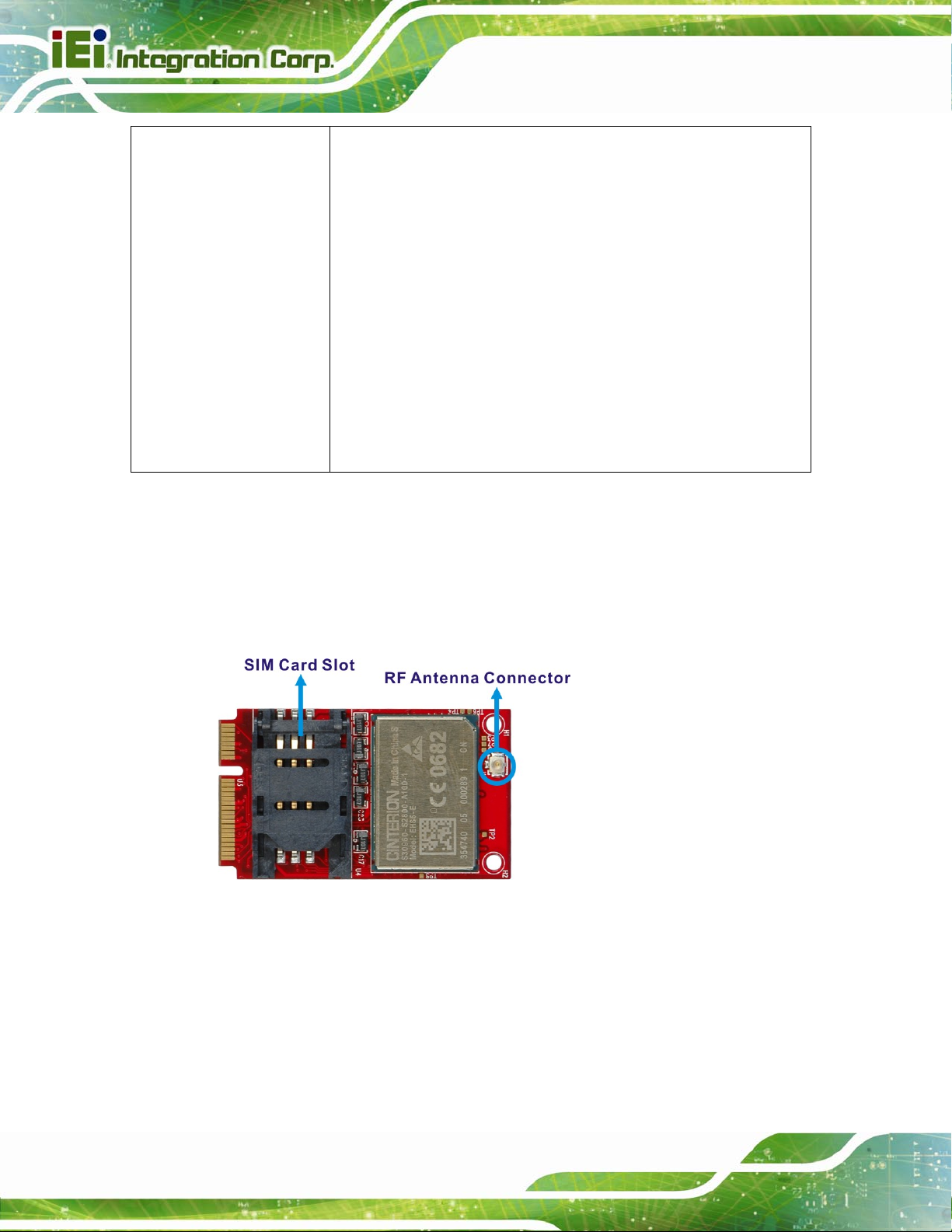
1.2 Hardware Installation
MPCIE-3G
Step 1: Install the MPCIE-3G card into the PCIe Mini full-size slot of the system. Please refer to
the system manual for the detail installation instruction.
Step 2: Connect the RF antenna cable to the RF antenna connector on the MPCIE-3G.
Step 3: Insert a SIM card into the SIM card slot on the MPCIE-3G.
Step 4: Connect the GSM antenna cable to the RF antenna cable connector.
Step 5: Power up the system.
Page 4
Page 5
MPCIE-3G
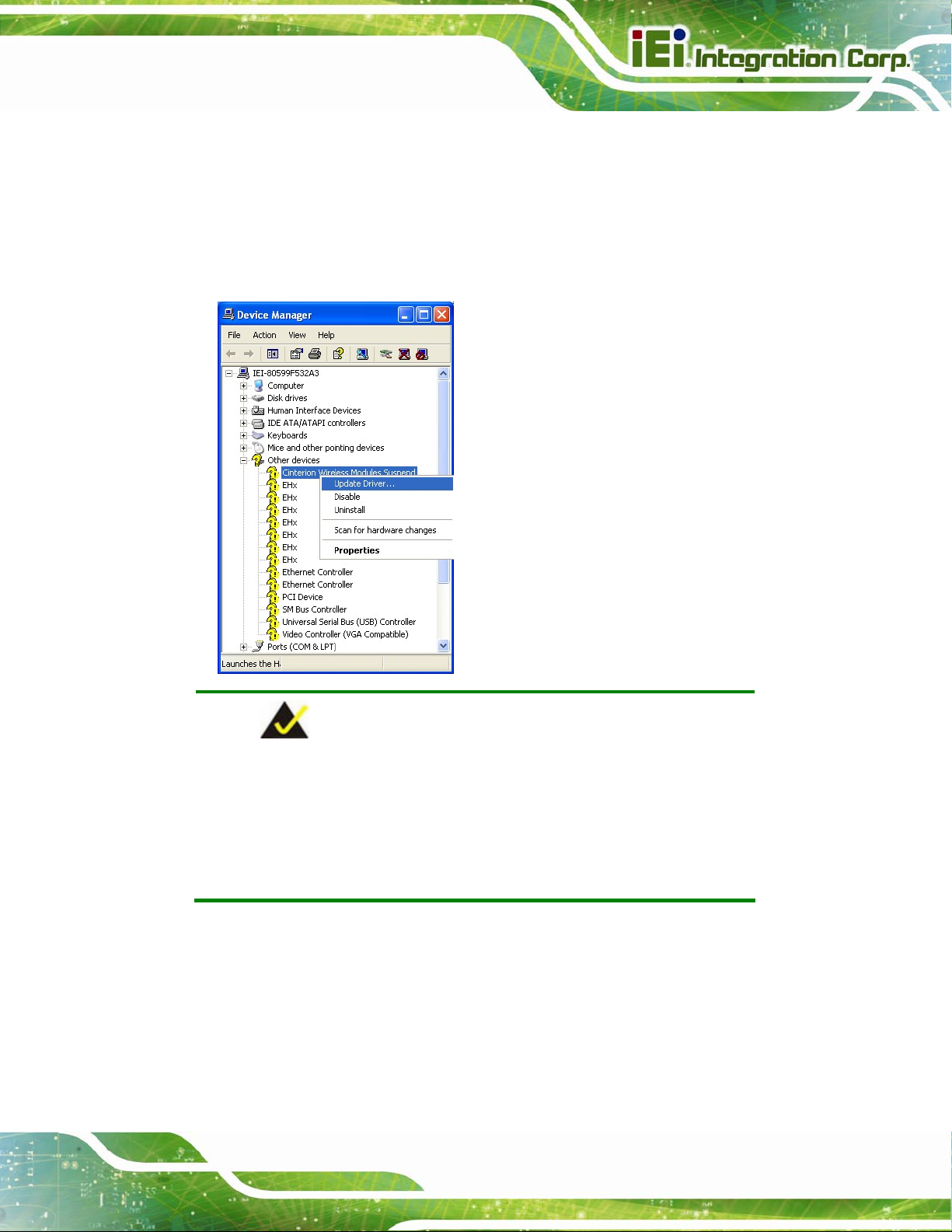
1.3 Software Installation
Step 1: Insert the MPCIE-3G driver CD into the system.
Step 2: Open the Device Manager. Right click on Cinterion Wireless Modules Suspend under
Other devices and select Update Driver Software.
NOTE:
There are seven further EHx ports located under “Other devices” that
are reserved for future use. The ports numbered 3, 4 and 5 provide an
AT command interface to the module via USB. Install the INF file for
these ports in the same way as for the USB modem if necessary.
Page 5
Page 6

MPCIE-3G
Step 3: The Hardware Update Wizard appears. Select “Yes, this time only” and click Next to
continue.
Step 4: Select “Install the software automatically” and click Next.
Page 6
Page 7

MPCIE-3G
Step 5: The Hardware Installation warning windows appears. Click “Continue Anyway”.
Step 6: The system starts installing drivers.
Page 7
Page 8

MPCIE-3G
Step 7: When the Hardware Update Complete window appears, click Finish to close the wizard.
Step 8: The Cinterion EHx USB Modem appears in the Device Manager under Modems.
Page 8
Page 9

MPCIE-3G
Step 9: Right click the Cinterion EHx USB Modem on the Device Manager and select
Properties. Click the Modem tab to display the selected COM port as well as the
maximum port speed.
Step 10: Click the Advanced tab to specify the Extra Initialization Commands:
AT+CGDCONT=1,”IP”,”[APN]”
NOTE:
[APN] stands for the APN information provided by the MNO of the SIM
card installed on the MPCIE-3G. Ensure that the SIM card does not
require a PIN.
Page 9
Page 10

MPCIE-3G
1.4 Create a Connection
Step 1: Open Control Panel. Select Network and Internet Connections Æ Network
Connections. Click “Create a new connection”.
Step 2: The New Connection Wizard appears. Click Next to continue.
Page 10
Page 11

MPCIE-3G
Step 3: Select a network connection type. Click Next to continue.
Page 11
Page 12

Step 4: Select “Set up my connection manually”. Click Next to continue.
MPCIE-3G
Step 5: Select “Connect using a dial-up modem”. Click Next to continue.
Page 12
Page 13

MPCIE-3G
Step 6: Type a name for this connection. Click Next to continue.
Step 7: Enter the Internet Service Provider settings in the following two setup windows. The
information should be provided by the MNO of the installed SIM card, including phone
number, user name and password. Click Next to continue.
Page 13
Page 14

MPCIE-3G
Step 8: The setup steps are completed. To create the connection and close the wizard, click
Finish.
Page 14
 Loading...