

Page 1

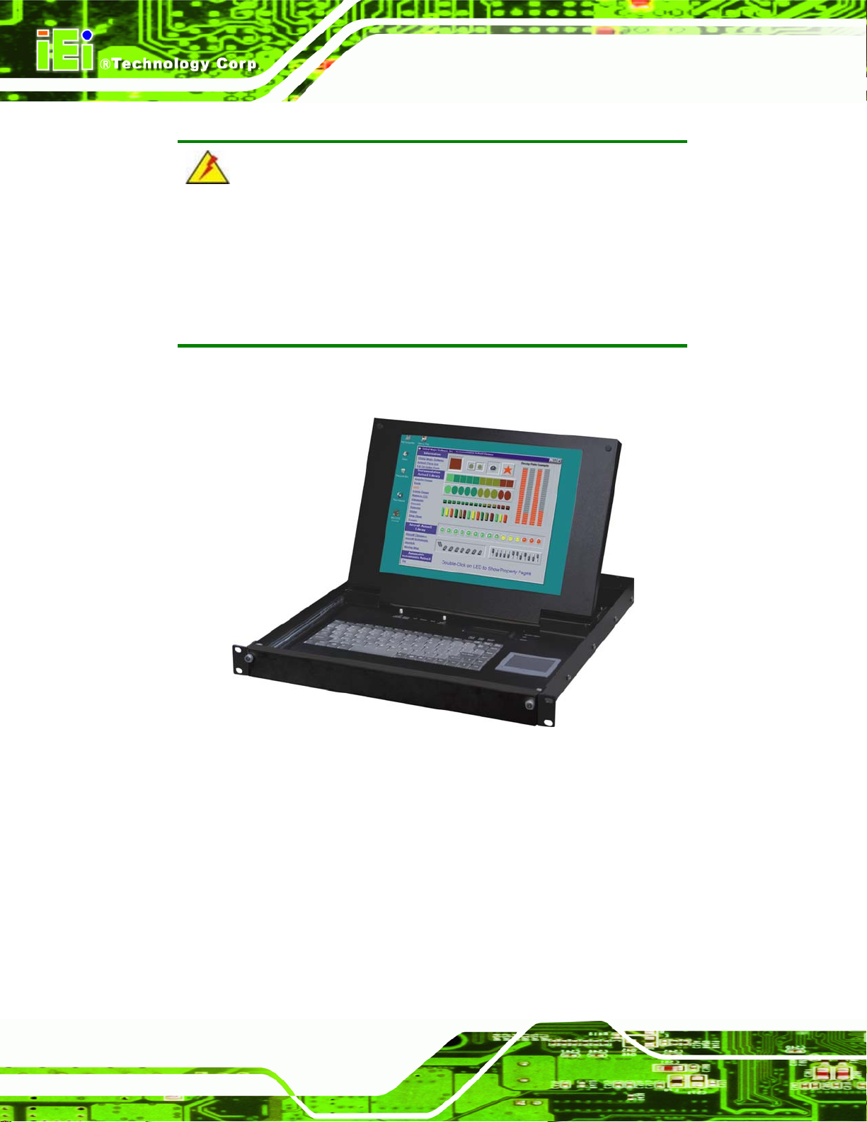
LKM Series Console Drawer
Page i
Page 2
KINO-LUKE-R20 Half-size CPU Card
LKM Series Console Drawer
Date Version Changes
2007-08-15 1.01 Added LKM-927 series
Updated formatting
2006-11-06 1.00 Initial release
Revision
Page ii
Page 3

LKM Series Console Drawer
COPYRIGHT NOTICE
The information in this document is subject to change without prior notice in order to
improve reliability, design and function and does not represent a commitment on the part
of the manufacturer.
In no event will the manufacturer be liable for direct, indirect, special, incidental, or
consequential damages arising out of the use or inability to use the product or
documentation, even if advised of the possibility of such damages.
Copyright
This document contains proprietary information protected by copyright. All rights are
reserved. No part of this manual may be reproduced by any mechanical, electronic, or
other means in any form without prior written permission of the manufacturer.
TRADEMARKS
All registered trademarks and product names mentioned herein are used for identification
purposes only and may be trademarks and/or registered trademarks of their respective
owners.
Page iii
Page 4
KINO-LUKE-R20 Half-size CPU Card
LKM Series Console Drawer
Manual Conventions
WARNING!
Warnings appear where overlooked details may cause damage to the equipment or result
in personal injury. Warnings should be taken seriously. Warnings are easy to recognize.
The word “warning” is written as “WARNING,” both capitalized and bold and is followed by
text. The text is the warning message. A warning message is shown below:
WARNING:
This is an example of a warning message. Failure to adhere to warning
messages may result in permanent damage to the LKM series console
or personal injury to the user. Please take warning messages seriously.
CAUTION!
Cautionary messages should also be heeded to help reduce the chance of losing data or
damaging the LKM series console. Cautions are easy to recognize. The word “caution” is
written as “CAUTION,” both capitalized and bold and is followed. The italicized text is the
cautionary message. A caution message is shown below:
Page iv
Page 5
LKM Series Console Drawer
CAUTION:
This is an example of a caution message. Failure to adhere to cautions
messages may result in permanent damage to the LKM series console.
Please take caution messages seriously.
NOTE:
These messages inform the reader of essential but non-critical information. These
messages should be read carefully as any directions or instructions contained therein can
help avoid making mistakes. Notes are easy to recognize. The word “note” is written as
“NOTE,” both capitalized and bold and is followed by text. The text is the cautionary
message. A note message is shown below:
NOTE:
This is an example of a note message. Notes should always be read.
Notes contain critical information about the LKM series console. Please
take note messages seriously.
Page v
Page 6
KINO-LUKE-R20 Half-size CPU Card
LKM Series Console Drawer
NOTE:
If any of the components listed in the checklist below are missing,
please do not proceed with the installation. Contact the IEI reseller or
vendor you purchased the LKM series console from or contact an IEI
sales representative directly. To contact an IEI sales representative,
Packing List
please send an email to sales@iei.com.tw
The items listed below should all be included in the package.
1 x LKM series console drawer
1 x Power adapter
1 x Power cable
2 x Rack mounting brackets (long)
2 x Rack mounting brackets (short)
1 x 1.8M Cable set (VGA, keyboard, mouse and audio - single port model )
1 x Screw set
1 x User Manual
Images of the above items are shown in Chapter 3.
.
Page vi
Page 7
LKM Series Console Drawer
Table of Contents
1 INTRODUCTION..................................................................................................... 1
1.1 LKM SERIES CONSOLE DRAWER OVERVIEW............................................................. 2
1.1.1 LKM Series Console Drawer Introduction........................................................ 2
1.1.2 LKM Series Console Drawer Features.............................................................. 3
1.1.3 LKM Series Console Drawer Benefits............................................................... 3
1.1.4 Model Variations................................................................................................ 4
1.1.5 Model Options.................................................................................................... 5
1.2 MECHANICAL OVERVIEW........................................................................................... 5
1.2.1 LKM Series Overview........................................................................................ 5
1.2.2 LKM Keyboard Tray .......................................................................................... 6
1.2.3 LKM Side View................................................................................................... 8
1.2.3.1 LKM-926 Side View................................................................................... 8
1.2.3.2 LKM-935 Side View................................................................................... 9
1.2.4 LKM Access Door............................................................................................ 10
1.2.5 LKM Rear View.................................................................................................11
1.2.5.1 Single Port KVMA ....................................................................................11
1.2.5.2 KVMA 8-Port Switch ................................................................................11
1.3 CERTIFICATIONS....................................................................................................... 12
AINTENANCE AND TROUBLESHOOTING ................................................................. 12
1.4 M
2 DETAILED SPECIFICATIONS........................................................................... 13
2.1 SERIES SPECIFICATIONS ........................................................................................... 14
2.2 PHYSICAL DIMENSIONS............................................................................................ 16
2.2.1 General Physical Dimensions.......................................................................... 16
2.2.2 LKM-926 Physical Dimensions ....................................................................... 17
2.2.3 LKM-927 Physical Dimensions ....................................................................... 18
2.2.4 LKM-935 Physical Dimensions ....................................................................... 19
2.2.5 LCD Specifications .......................................................................................... 20
2.3 POWER ADAPTERS ................................................................................................... 21
2.3.1 5V/12V AC/DC Power Adapter........................................................................ 21
2.3.2 24V/48V DC Input Power Adapters................................................................. 23
Page vii
Page 8

KINO-LUKE-R20 Half-size CPU Card
LKM Series Console Drawer
3 INSTALLATION .................................................................................................... 25
NSTALLATION PRECAUTIONS................................................................................... 26
3.1 I
3.2 UNPACKING.............................................................................................................. 26
3.2.1 Packaging ........................................................................................................ 26
3.2.2 Unpacking Procedure ...................................................................................... 27
3.2.3 Packing List ..................................................................................................... 28
3.2.4 Optional Accessories........................................................................................ 28
3.3 PRE-INSTALLATION PREPARATION ............................................................................ 28
3.3.1 Tools ................................................................................................................. 28
3.4 CONNECTORS........................................................................................................... 29
3.4.1 Audio Connector .............................................................................................. 29
3.4.2 Keyboard Connector........................................................................................ 30
3.4.3 Mouse Connector............................................................................................. 31
3.4.4 Power Connector............................................................................................. 32
3.4.5 VGA Connector................................................................................................ 33
3.5 M
OUNTING THE LKM SERIES CONSOLE DRAWER ................................................... 34
3.5.1 Rack Mounting................................................................................................. 34
3.6 CABLING.................................................................................................................. 39
4 ON-SCREEN-DISPLA Y AND LCD MODULE CONTROLS ........................... 41
4.1 OSD CONTROLS ...................................................................................................... 42
4.1.1 OSD Buttons..................................................................................................... 42
4.1.2 OSD Menu Structure........................................................................................ 42
4.1.3 Brightness and Contrast Menu ........................................................................ 44
4.1.4 Color Menu...................................................................................................... 45
4.1.4.1 Color Temperature Sub-Menu .................................................................. 46
4.1.4.2 User Sub-Menu......................................................................................... 47
4.1.5 Image Menu ..................................................................................................... 48
4.1.6 Tools Menu....................................................................................................... 49
4.1.6.1 OSD Sub-Menu......................................................................................... 50
4.2 LCM C
ONTROLS (8-PORT KVMA MODELS)........................................................... 51
4.2.1 LCM Buttons.................................................................................................... 51
4.2.2 LCM Functions ................................................................................................ 52
4.2.2.1 Manually Switching Stations.................................................................... 52
4.2.2.2 Cycling Through Stations......................................................................... 52
Page viii
Page 9
LKM Series Console Drawer
4.2.2.3 Station Name Editing................................................................................ 52
A SAFETY PRECAUTIONS..................................................................................... 55
AFETY PRECAUTIONS ............................................................................................ 56
A.1 S
A.1.1 General Safety Precautions............................................................................. 56
A.1.2 Anti-static Precautions.................................................................................... 57
A.2 MAINTENANCE AND CLEANING PRECAUTIONS........................................................ 58
A.2.1 Maintenance and Cleaning.............................................................................. 58
A.2.2 Cleaning Tools................................................................................................. 58
B HAZARDOUS MATERIALS DISCLOSURE..................................................... 61
B.1 H
AZARDOUS MATERIAL DISCLOSURE TABLE FOR IPB PRODUCTS CER TIFIED AS
ROHS COMPLIANT UNDER 2002/95/EC WITHOUT MERCURY....................................... 62
C INDEX...................................................................................................................... 65
Page ix
Page 10

KINO-LUKE-R20 Half-size CPU Card
LKM Series Console Drawer
List of Figures
Figure 1-1: LKM Console Drawer.................................................................................................2
Figure 1-2: LKM General Overview..............................................................................................6
Figure 1-3: LKM Keyboard Tray...................................................................................................7
Figure 1-4: LKM-926 Side View ....................................................................................................8
Figure 1-5: LKM-935 Series Overview.........................................................................................9
Figure 1-6: LKM-926/927 Access Door......................................................................................10
Figure 1-7: Single Port KVMA Rear View..................................................................................11
Figure 1-8: 8-Port KVMA Rear View...........................................................................................11
Figure 2-1: LKM-926 Physical Dimensions (millimeters) ........................................................17
Figure 2-2: LKM-927 Physical Dimensions (millimeters) ........................................................18
Figure 2-3: LKM-935 Physical Dimensions (millimeters) ........................................................19
Figure 2-4: 5V/12V AC/DC Power Adapter ................................................................................22
Figure 2-5: 5V/12V AC/DC Power Adapter Dimensions (millimeters [inches]) .....................22
Figure 2-6: 24V/48V DC Power Adapter Dimensions (millimeters).........................................24
Figure 3-1: Keyboard Connector ...............................................................................................30
Figure 3-2: Mouse Connector.....................................................................................................31
Figure 3-3: 5V/12V Power Connector ........................................................................................32
Figure 3-4: VGA Connector ........................................................................................................33
Figure 3-5: Attach the Rack Mounting Bracket ........................................................................35
Figure 3-6: Attach the Angle Bracket........................................................................................36
Figure 3-7: Secure Front of Console to Rack...........................................................................37
Figure 3-8: Secure Rear of Console to Rack ............................................................................38
Figure 3-9: Rear Panel Connections..........................................................................................39
Figure 4-1: OSD Control Buttons...............................................................................................42
Figure 4-2: Brightness and Contrast Menu...............................................................................44
Figure 4-3: Color Menu ...............................................................................................................45
Figure 4-4: Color Temperature Sub-Menu ................................................................................46
Page x
Page 11

LKM Series Console Drawer
Figure 4-5: User Sub-Menu.........................................................................................................47
Figure 4-6: Image Menu ..............................................................................................................48
Figure 4-7: Tools Menu...............................................................................................................49
Figure 4-8: OSD Sub-Menu.........................................................................................................50
Figure 4-9: LCM Control Buttons...............................................................................................51
Page xi
Page 12

KINO-LUKE-R20 Half-size CPU Card
LKM Series Console Drawer
List of Tables
Table 1-1: LKM Series Console Drawer Model Variations.........................................................4
Table 2-1: LKM Series Specifications........................................................................................15
Table 2-2: General Physical Dimensions..................................................................................16
Table 2-3: LKM Series console drawer LCD Specifications....................................................20
Table 2-4: 5V/12V AC/DC Power Adapter Specifications ........................................................21
Table 2-5: 24V/48V DC Power Adapter Specifications.............................................................23
Table 3-1: Rear Panel Connectors.............................................................................................29
Table 3-2: Keyboard Connector Pinouts...................................................................................30
Table 3-3: Mouse Connector Pinouts........................................................................................31
Table 3-4: 5V/12V Power Connector Pinouts............................................................................32
Table 3-5: VGA Connector Pinouts............................................................................................33
Table 4-1: OSD Menu Structure..................................................................................................43
Page xii
Page 13
LKM Series Console Drawer
Glossary
AC ’97 Audio Codec 97
ACPI Advanced Configuration and
Power Interface
APM Advanced Power Management
ARMD ATAPI Removable Media Device
ASKIR Shift Keyed Infrared
ATA Advanced Technology
Attachments
BIOS Basic Input/Output System
CFII Compact Flash Type 2
CMOS Complementary Metal Oxide
Semiconductor
CPU Central Processing Unit
Codec Compressor/Decompressor
COM Serial Port
DAC Digital to Analog Converter
DDR Double Data Rate
HDD Hard Disk Drive
IDE Integrated Data Electronics
I/O Input/Output
ICH4 I/O Controller Hub 4
L1 Cache Level 1 Cache
L2 Cache Level 2 Cache
LCD Liquid Crystal Display
LPT Parallel Port Connector
LVDS Low Voltage Differential Signaling
MAC Media Access Controller
OS Operating System
PCI Peripheral Connect Interface
PIO Programmed Input Output
PnP Plug and Play
POST Power On Self Test
RAM Random Access Memory
SATA Serial ATA
DIMM Dual Inline Memory Module
DIO Digital Input/Output
DMA Direct Memory Access
EIDE Enhanced IDE
EIST Enhanced Int el SpeedStep
Technology
FDD Floppy Disk Drive
FDC Floppy Disk Connector
FFIO Flexible File Input/Output
FIFO First In/First Out
FSB Front Side Bus
IrDA Infrared Data Association
S.M.A.R.T Self Monitoring Analysis and
Reporting Technology
SPD Serial Presence Detect
S/PDI Sony/Philips Digital Interface
SDRAM Synchronous Dynamic Random
Access Memory
SIR Serial Infrared
UART Universal Asynchronous
Receiver-transmitter
USB Universal Serial Bus
VGA Video Graphics Adapter
Page xiii
Page 14

THIS PAGE IS INTENTIONALLY LEFT BLANK
Page xiv
Page 15
LKM Series Console Drawer
1 Introduction
Chapter
1
Page 1
Page 16
LKM Series Console Drawer
WARNING:
All safety guidelines are specified in Appendix A. Failure to adhere to
the safety and maintenance guidelines in Appendix A may result in
permanent damage to the LKM series console drawer and/or serious or
fatal injuries to the user.
1.1 LKM Series Console Drawer Overview
Figure 1-1: LKM Console Drawer
1.1.1 LKM Series Console Drawer Introduction
The LKM Series console drawer is designed for IT professionals with up to eight ports for
leveraging the power of existing server networks with minimal intrusion. Highly efficient,
the LKM Series console drawer allows centralized access and control of up to eight
computers from an integrated 1U console with a built-in 15” or 17” LCD display, one or
eight port KVMA switch, keyboard and touch pad.
Page 2
Page 17

LKM Series Console Drawer
The LKM Series console drawer is designed to deliver considerable return on investment.
Saving time, money and valuable server room real estate, it can be rack mounted at any
user-height. With a host of advanced features designed to protect your investment, the
series includes: intelligent OSD (On Screen Display) menus, hot key switching,
auto-sensing of computers and multi-language support.
Whether it’s in educational, government, or corporate sectors, the LKM Series console
drawer provides network and IT managers a stable management tool for multiple
computer access and control.
1.1.2 LKM Series Console Drawer Features
Some of the features of the LKM Series console drawer include:
Ability to connect up to 8 computers
Keyboard, mouse, audio and VGA connection ports for each computer
15" or 17" high brightness TFT LCD display
Standard keyboard and touch pad
Keyboard languages supported: German, English, French, Italian, Japanese,
Russian, Spanish and Traditional Chinese
Two internal spe akers for stereo audio output
1U high slim body design saves rack space
LCD module (LCM) - channel change control, auto scan control,
programmable station naming (8-port KVMA models only)
Hot Pluggable - add or remove computers without having to power down the
switch
Supported OSes: Windows 98SE, 2000, XP, ME, Linux and Unix
1.1.3 LKM Series Console Drawer Benefits
Some of the benefits of the LKM Series console drawer include:
Control and access multiple computers from a central user console instead of
moving from one to another .
Save hundreds of dollars in equipment, space, and power cost s as there is no
need for additional peripherals for each computer.
Page 3
Page 18
LKM Series Console Drawer
Installation is as simple as connecting cables between the KVMA switch and
computers.
Ideal for an Internet data center, server room, testing lab, and
network-operating center where multiple computers are required.
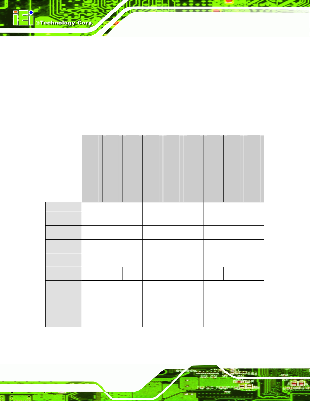
1.1.4 Model Variations
The LKM Series console drawer comes in a variety of models. The models have special
features as identified by their model name. The LKM Series console drawer model
variations are listed in Table 1-1.
LKM-926(8)G(C) - (L)
LCD Size 15” 17” 15”
Keyboard Yes Yes Yes
Mouse Yes Yes Yes
Speaker Yes Yes Yes
Drawer Size 1U 1U 1U
Power Input AC 48VDC 24VDC AC 48VDC 24VDC AC 48VDC 24VDC
Separate LCD
and
Keyboard
Accessibility
Table 1-1: LKM Series Console Drawer Model Variations
LKM-926(8)G(C) - T - (L)
No No Yes
LKM-926(8)G(C) - C - (L)
LKM-927(8)G(C) - (L)
LKM-927(8)G(C) - T - (L)
LKM-927(8)G(C) - C - (L)
LKM-935(8)G(C) - (L)
LKM-935(8)G(C) - T - (L)
LKM-935(8)G(C) - C - (L)
Page 4
Page 19
LKM Series Console Drawer
1.1.5 Model Options
Table 1-1 lists the standard features for the LKM Series console drawer model variations.
However, there are a variety of additional options available for the LKM Series console
drawer as identified by specific product codes. The product code options for the LKM
Series console drawer are:
(8) – specifies an eight port KVMA switch; these models also include an LCD
module (LCM) on the keyboard tray.
(C) – specifies color
o B: black
o W: white
(L) – specifies keyboard language
o DE: German
o EN: English
o FR: French
o IT: Italian
o JP: Japanese
o RU: Russian
o SP: Spanish
o TW: Traditional Chinese
For example, LKM-9268GB-EN would indicate an LKM-926 model with an eight-port
KVMA switch, black color with an English keyboard.
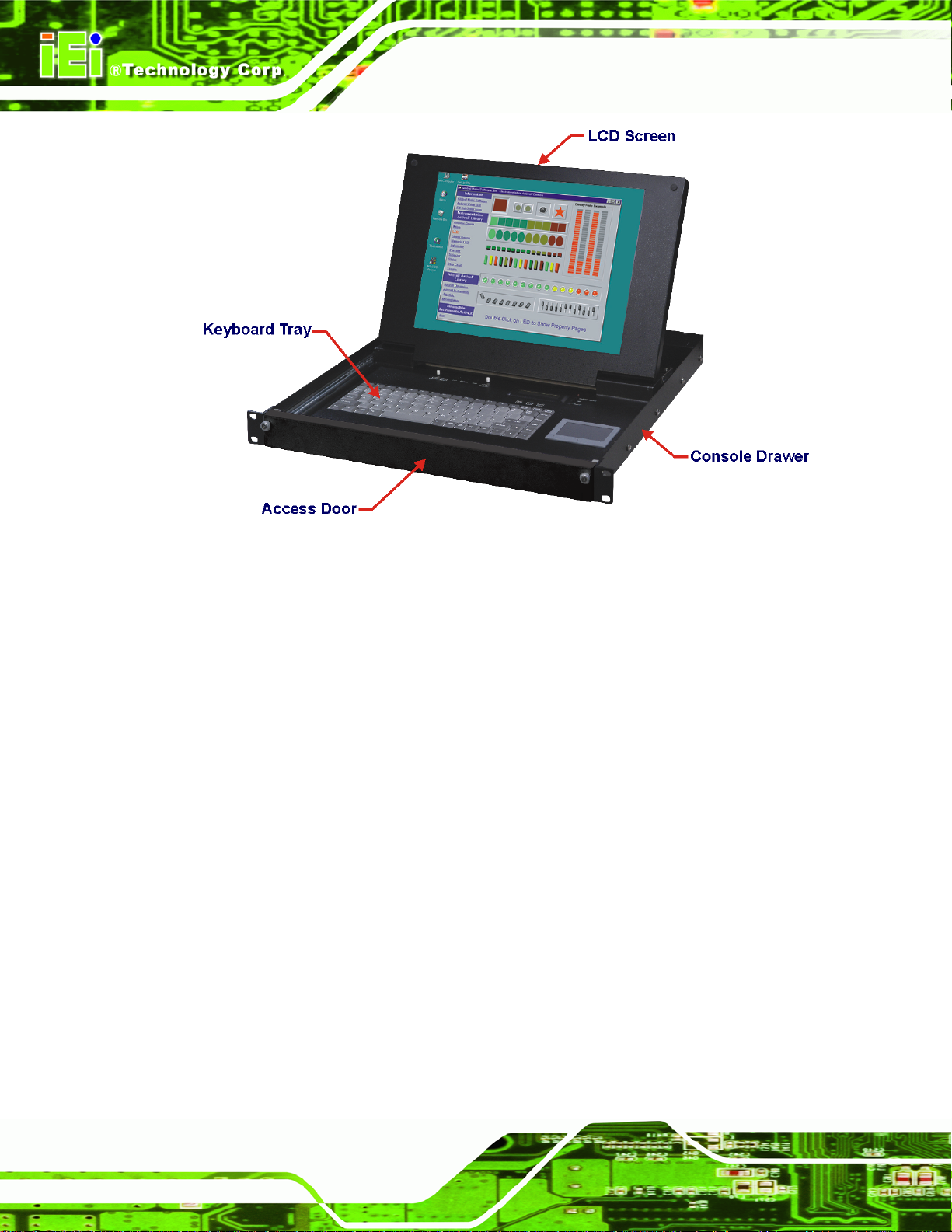
1.2 Mechanical Overview
This section describes a general physical overview of the LKM series console drawers.
1.2.1 LKM Series Overview
The LKM series console drawer consists of a rail-mounted TFT LCD and keyboard tray
within a heavy-duty steel drawer. With the use of a mounting kit, the console drawer can
easily be mounted to a standard 19” rack. Figure 1-2 shows an overview of the LKM series
console drawer.
Page 5
Page 20
LKM Series Console Drawer
Figure 1-2: LKM General Overview
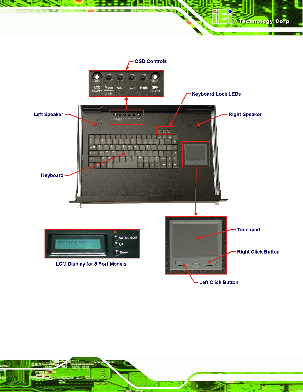
1.2.2 LKM Keyboard Tray
The keyboard tray consists of the following items:
87-key keyboard
Left and right speakers
LCD ON/OFF button
Speaker ON/OFF button
OSD control buttons
Keyboard lock LEDs
Touchpad with left and right-click buttons
LCM display and control buttons (8-port KVMA models only)
Page 6
Page 21
LKM Series Console Drawer
Figure 1-3 shows the LKM series console drawer keyboard tray.
Figure 1-3: LKM Keyboard Tray
Page 7
Page 22
LKM Series Console Drawer
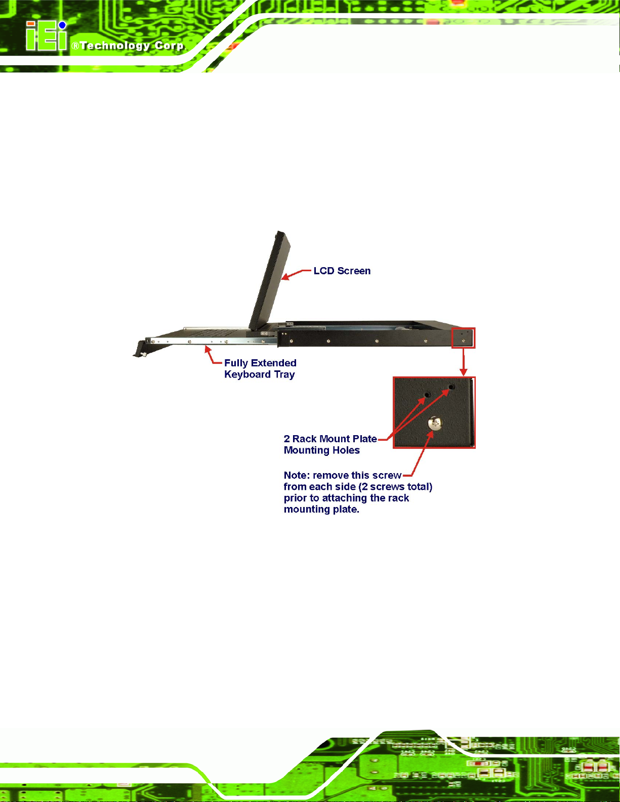
1.2.3 LKM Side View
1.2.3.1 LKM-926 Side View
The sides of the console drawer have holes for rack mounting. Refer to Section 3.5 for
complete mounting details. Figure 1-4 shows the side view of the LKM-926 series console
drawer.
Figure 1-4: LKM-926 Side View
Page 8
Page 23
LKM Series Console Drawer
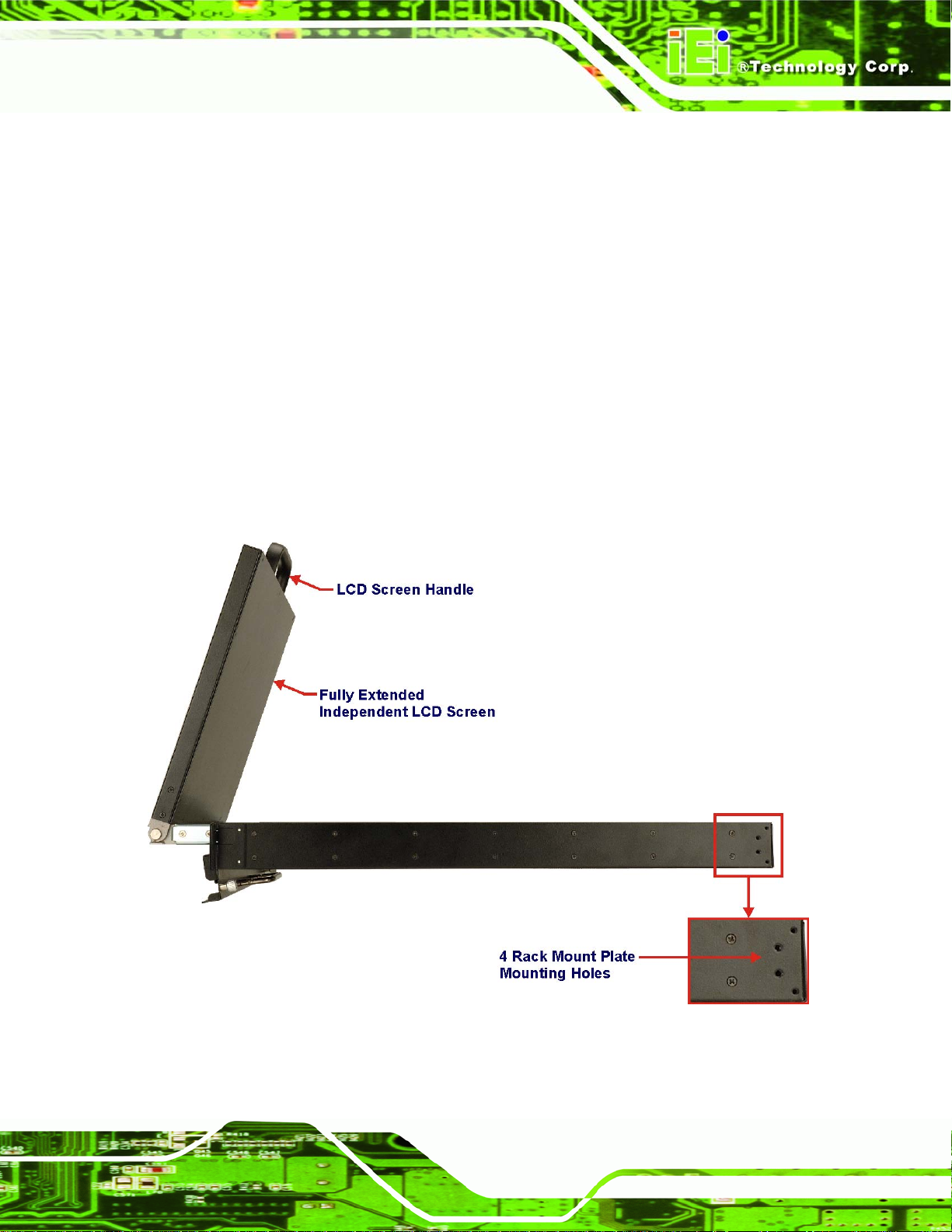
1.2.3.2 LKM-935 Side View
The LKM-935 series console drawer is similar to the LKM-926 series with the following
notable exceptions:
The access door and LCD screen each have an additional handle for easy
access.
The LCD screen and keyboard tray can move independently of one another
so that the LCD screen can be viewed while the keyboard tray is in the stowe d
position. Note that the keyboard tray cannot be accessed independently of the
LCD screen.
The sides of the drawer each have four holes for rack mounting.
Figure 1-5 shows the side view of the LKM-935 series console drawer.
Figure 1-5: LKM-935 Series Overview
Page 9
Page 24
LKM Series Console Drawer
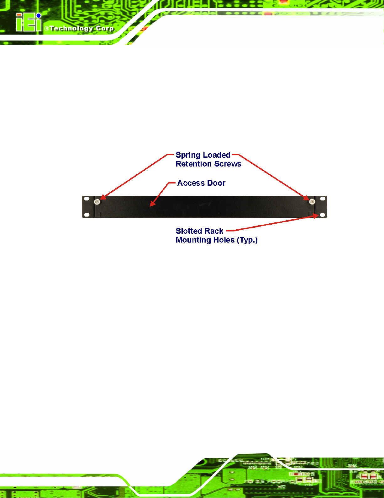
1.2.4 LKM Access Door
The front of the console drawer consists of an access door with two spring-loaded,
freewheeling retention screws for securing the access door when the LCD and keyboard
are in the stowed position. Also located on the front of the console drawer are two metal
clips with slotted holes for rack mounting. Refer to Section 3.5 for complete mounting
details. Figure 1-6 shows the access door of the LKM-926 series console drawer.
Figure 1-6: LKM-926/927 Access Door
Page 10
Page 25
LKM Series Console Drawer
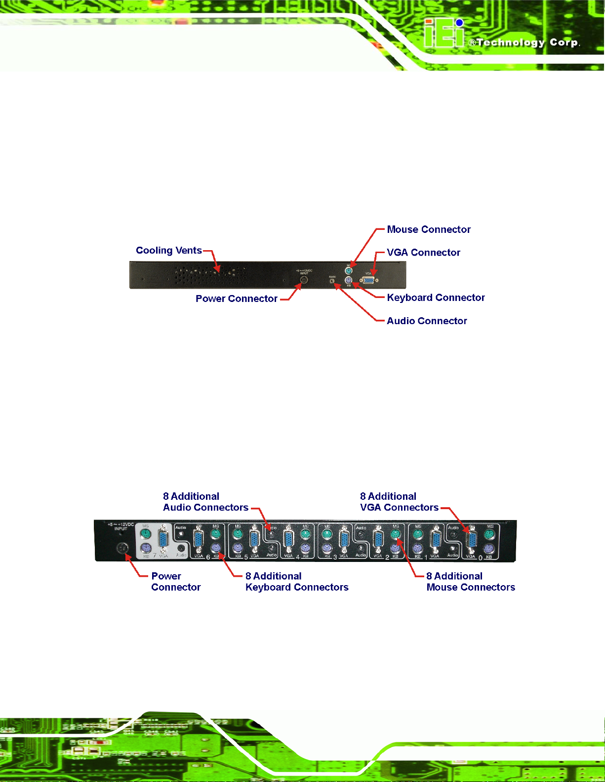
1.2.5 LKM Rear View
1.2.5.1 Single Port KVMA
The rear panel of the drawer consists of industry standard VGA, keyboard, mouse and
audio connectors, as well as a power connector and cooling vents. Figure 1-7 shows the
rear view of the LKM-926 series console drawer.
Figure 1-7: Single Port KVMA Rear View
1.2.5.2 KVMA 8-Port Switch
The KVMA 8-port switch can be used to connect up to eight systems to the LKM series
console drawer. Each system can be connected to the console via its own standard audio,
VGA, keyboard and mouse connectors. Each system can be easily accessed through the
LCM on the keyboard tray (see Figure 1-3). Figure 1-8 shows the KVMA 8-port switch.
Figure 1-8: 8-Port KVMA Rear View
Page 11
Page 26

LKM Series Console Drawer
1.3 Certifications
All LKM series console drawer models comply with the following international standard:
RoHS
For a more detailed description of this standard, please refer to Appendix B.
1.4 Maintenance and Troubleshooting
All LKM series console drawer models require no maintenance and should provide
trouble-free service. If any component of an LKM series console drawer fails to operate,
malfunctions, or otherwise appears to be broken, do not attempt to fix it. Return the
malfunctioning LKM series console drawer in its entirety to the original reseller, vendor or
to IEI for repair or replacement.
Page 12
Page 27

LKM Series Console Drawer
Chapter
2
2 Detailed Specifications
Page 13
Page 28

LKM Series Console Drawer
2.1 Series Specifications
Table 2-1 shows the LKM Series console drawer specifications.
LKM-926 series LKM-927 series LKM-935 series
LCD Type
Input Interface
Max.
Resolution
Backlight
MTBF
Contrast
LCD Color
Brightness
(cd/m2)
Power Adapter
Chassis
17" TFT 15" TFT 15" TFT
XGA SXGA XGA
1024x768 1280x1024 1024x768
50,000 Hrs 50,000 Hrs 50,000 Hrs
400:1 800:1 400:1
262K 16.7M 262K
350 300 350
42W AC/DC Adapter
Heavy-duty steel
Page 14
View Angle
(H/V)
OSD function
Mounting
Rack Height
Keyboard
Touch Pad
LCM
120°/100° 160°/160° 120°/100°
Yes
19” Rack Mount
1U
87 Keys – Slim Size
Yes – with 2 buttons
8 Port KVMA Models Only
Page 29

LKM Series Console Drawer
LKM-926 series LKM-927 series LKM-935 series
Independent
No No Yes
KB/LCD Trays
Dimensions
(L x W x H)
(mm)
Weight
(Gross/Net)
Color
Vibration
Shock
Humidity
Operation
Temperature
Table 2-1: LKM Series Specifications
521 x 432.6 x 44 572 x 436 x 44 536 x 433.6 x 44
17Kg 17Kg 17Kg
Black (Pantone Black C), White (Pantone 413C)
5 ~ 17 Hz, 0.1” double amplitude displacement
17 ~ 640 Hz, 1.5G acceleration peak to peak
10G acceleration peak to peak (11ms)
5 ~ 95%, non-condensing
0~50°C
Page 15
Page 30

LKM Series Console Drawer
2.2 Physical Dimensions
The following sections describe the physical dimen sions for each m odel of the LK M Series
console drawer.
2.2.1 General Physical Dimensions
General physical dimensions for the LKM Series console drawer s are shown i n Table 2-2.
Model Length
(mm)
LKM-926 521 432.6 44
LKM-927 572 436 44
LKM-935 536 433.6 44
Table 2-2: General Physical Dimensions
Width
(mm)
Height
(mm)
Page 16
Page 31

LKM Series Console Drawer
2.2.2 LKM-926 Physical Dimensions
The physical dimensions of the LKM-926 are shown in Figure 2-1.
Figure 2-1: LKM-926 Physical Dimensions (millimeters)
Page 17
Page 32

LKM Series Console Drawer
2.2.3 LKM-927 Physical Dimensions
The physical dimensions of the LKM-927 are shown in Figure 2-2.
Figure 2-2: LKM-927 Physical Dimensions (millimeters)
Page 18
Page 33

LKM Series Console Drawer
2.2.4 LKM-935 Physical Dimensions
The physical dimensions of the LKM-935 are shown in Figure 2-3.
Figure 2-3: LKM-935 Physical Dimensions (millimeters)
Page 19
Page 34

LKM Series Console Drawer
2.2.5 LCD Specifications
Table 2-3 lists the LKM Series console drawer LCD specifications.
Size 15" 17"
Mfr./Model
Resolution (pixel)
Active Area
(H x V)(mm)
Pixel Pitch (mm)
Mode
Number of Colors
View Angle (H/V)
Brightness (cd/m²)
Contrast Ratio
Response Time
(ms) (at 25°C)
AUO / G150XG01 AUO / M170EG01 VD
XGA (1024 x 768) SXGA (1280 x 1024)
304.1 x 228.1 337.920 x 270.336
0.297 0.264
TN TN
262K 16.7M
120°/100° 160°/160°
350 300
400:1 800:1
16ms (Tr+Tf) 5ms (Tr+Tf)
Power Consumption
Lamp Life (hrs)
Table 2-3: LKM Series console drawer LCD Specifications
Page 20
Interface
Backlight
11.5W 25.8W
Single Channel LVDS Dual Channel LVDS
2 CCFL 4 CCFL
50,000 50,000
Page 35

LKM Series Console Drawer
2.3 Power Adapters
2.3.1 5V/12V AC/DC Power Adapter
Table 2-4 lists the 5V/12V AC/DC power adapter specifications.
MFR./Model Sinpro/SPU45E-201
Power 42 Watt AC/DC Adapter
General Description Universal Input 90 to 264 VAC
Input Voltage Range 90-264VAC
EMI Meets FCC Part-15/CISPR 22 Class B
MTBF 100Khrs
Input Frequency 47-63 Hz
Inrush Current 30A max. (Cold Start)
Hold-up Time 10mS typical
Leakage Current 0.75mA max.
Short Circuit Protection Continuous
Over-voltage Protection Yes
Continuous Output Power 42W max.
Hi-pot Isolation: Input / Output 42/42VDC
Table 2-4: 5V/12V AC/DC Power Adapter Specifications
Page 21
Page 36

LKM Series Console Drawer
The 5V/12V AC/DC power adapter is shown in Figure 2-4.
Figure 2-4: 5V/12V AC/DC Power Adapter
The physical dimensions of the 5V/12V AC/DC power adapter are shown in Figure 2-5.
Figure 2-5: 5V/12V AC/DC Power Adapter Dimensions (millimeters [inches])
Page 22
Page 37

LKM Series Console Drawer
2.3.2 24V/48V DC Input Power Adapters
Table 2-5 lists the 24V/48V DC power adapter specifications.
MFR./Model Skynet / ACE-023C Skynet / ACE-023T
EMI Standards FCC Docket 20780 curve”B” EN 55022”B”
IEC-61000-4-2: 4KV contact; 8KV air discharge criterion B
EMS Standards
Input Voltage Range 18VDC - 32VDC 36VDC - 72VDC
Input Current 2.5A max. at 24VDC
Inrush Current 15A max. at 24VDC (25º Cold Start)
Output Load Range
Output Power >30W at 24VDC
24V DC Input 48V DC Input
IEC-61000-4-3: 3V/M with 80% AM criterion A
IEC-61000-4-4: 2KV criterion B
+5V output, 4A rated load
+12V output, 0.75A rated load
Ripple and Noise >1.2% of output voltage peak to peak
Line Regulation >±1% at rated load
Load Regulation 5V >±5% and 12V >±4% at 60% rated load, 24VDC input
Short Circuit Protection Continuous
Over-voltage Protection Yes
Humidity 20 ~ 95%, non-condensing
Operation Temperature 0 ~ 50°C
Storage Temperature -40 ~ 85°C
Table 2-5: 24V/48V DC Power Adapter Specifications
Page 23
Page 38

LKM Series Console Drawer
The physical dimensions of the 24V/48V DC power adapter are shown in Figure 2-6.
Figure 2-6: 24V/48V DC Power Adapter Dimensions (millimeters)
Page 24
Page 39

LKM Series Console Drawer
Chapter
3
3 Installation
Page 25
Page 40

LKM Series Console Drawer
3.1 Installation Precautions
When installing the LKM series console drawer, please follow the precautions listed
below:
Read the user manual: The user manual provides a complete description of
the LKM series console drawer, installation instructions and configuration
options.
DANGER! Disconnect Power: Power to the console drawer must be
disconnected when installing the LKM series console drawer.
Qualified Personnel: The LKM series console drawer must be installed and
operated only by trained and qualified personnel. Maintenance may only be
carried out by qualified personnel who are familiar with the associated
dangers.
Mounting: Since the LKM series console drawer may weigh up to 11Kg,
please ensure at least two people assist with mounting the drawer.
Air Circulation: Make sure there is sufficient air circulation when inst alling the
LKM series console drawer . The LKM series console drawer’s cooling vents
must not be obstructed by any objects. Blocking the vents can cause
overheating of the LKM series console drawer .
Grounding: The LKM series console drawer should be properly grounded.
The voltage feeds must not be overloaded. Adjust the cabling and provide
external overcharge protection per the electrical values indicated on the label
attached to the power adapter.
3.2 Unpacking
3.2.1 Packaging
When shipped, the LKM series console drawer is wrapped in a plastic bag. Two
polystyrene ends are placed on either side of the console drawer. The console drawer is
then placed into a first (internal) cardboard box. This box is then sealed and placed into a
second (external) cardboard box. The second box is also sealed. Two bags containing
accessory items are placed with the console drawer in the internal (first) box.
Page 26
Page 41

LKM Series Console Drawer
3.2.2 Unpacking Procedure
To unpack the LKM series console drawer, follow the steps below:
WARNING:
The LCD screen has a protective plastic cover stuck to the screen. Remove
the plastic cover only after the LKM series console drawer has been
properly installed. This ensures the screen is protected during the
installation process.
Step 1: Use a box cutter, a knife or a sharp pair of scissors to cut the tape that seals the
top side of the external (second) box.
Step 2: Open the external (second) box.
Step 3: Use a box cutter, a knife or a sharp pair of scissors to cut the tape that seals the
top side of the internal (first) box.
Step 4: Lift the console drawer out of the boxes.
Step 5: Remove both polystyrene ends, one from each side.
Step 6: Pull the plastic cover off the console drawer.
Step 7: Make sure all the components listed in the pa cking list are present. Step 0:
Page 27
Page 42

LKM Series Console Drawer
3.2.3 Packing List
All the console drawers in the LKM series are shipped with the following components:
Quantity Item and Par t Numbe r Image
1 LKM Console Drawer
1 1.8m Cable Set, Including VGA, Keyboard,
(single-port
model)
1 175cm Round Cable Power Cord
1 Power Supply
2 Rack Mounting Bracket (Long)
2 Rack Mounting Bracket (Short)
Mouse and Audio Cable
(P/N: LKM-CB18A-RS)
(P/N: 32000-000002-RS)
(P/N: 63SPU45E201-000-RS)
(P/N: 41020-009001-01-RS)
(P/N: 41020-009501-00-RS)
Page 28
1 Screw Set (8x Rack Mounting Screws)
1 Quick installation guide
Page 43

LKM Series Console Drawer
If any of these items is missing or damaged, contact the distributor or sales representative
immediately.
3.2.4 Optional Accessories
The following optional accessories for the LKM series console drawers can be ordered
separately:
Item and Part Number Image
1.8m Cable Set, Including VGA, Keyboard, Mouse
and Audio Cable
(P/N: LKM-CB18A-RS)
3.0m Cable Set, Including VGA, Keyboard, Mouse
and Audio Cable
(P/N: LKM-CB30A-RS)
5.0m Cable Set, Including VGA, Keyboard, Mouse
and Audio Cable
(P/N: LKM-CB50A-RS)
3.3 Pre-installation Preparation
3.3.1 Tools
Before installing the LKM series console drawer, make sure the following tools are on
hand:
Philips (crosshead) screwdriver: All the retention screws on the system are
Philips screws.
Page 29
Page 44

LKM Series Console Drawer
3.4 Connectors
Table 3-1 lists the rear panel connectors for the LKM series console drawers.
Connector Type
Audio connector 1 x audio jack
Keyboard connector PS/2 connector
Mouse connector PS/2 connector
Power connector Mini DIN Plug With Lock (Thick Pin, 4 PIN) connector
VGA connector HD-D-sub 15 female connector
Table 3-1: Rear Panel Connectors
3.4.1 Audio Connector
To receive audio signals from a system, use the rear panel audio jack to connect to a
system’s line out audio jack connector.
Page 30
Page 45

LKM Series Console Drawer
3.4.2 Keyboard Connector
Use the rear panel PS/2 keyboard connector to connect the console keyboard to a
system.
Figure 3-1: Keyboard Connector
PIN DESCRIPTION
1 L_KDAT
2 NC
3 GND
4 5V
5 L_KCLK
6 NC
Table 3-2: Keyboard Connector Pinouts
Page 31
Page 46

LKM Series Console Drawer
3.4.3 Mouse Connector
Use the rear panel PS/2 mouse connector to connect the console mouse to a system.
Figure 3-2: Mouse Connector
PIN DESCRIPTION
1 L_MDAT
2 NC
3 GND
4 5V
5 L_MCLK
6 NC
Table 3-3: Mouse Connector Pinouts
Page 32
Page 47

LKM Series Console Drawer
3.4.4 Power Connector
Use the rear panel power connector to connect the console to the power adapter.
Figure 3-3: 5V/12V Power Connector
PIN DESCRIPTION PIN DESCRIPTION
2 COMMON 1 +5V
4 COMMON 3 +12V
Shell GND
Table 3-4: 5V/12V Power Connector Pinouts
Page 33
Page 48

LKM Series Console Drawer
3.4.5 VGA Connector
Use the rear panel standard 15-pin female VGA connector to connect the monitor to the
system graphics interface.
PIN DESCRIPTION PIN DESCRIPTION PIN DESCRIPTION
1 RED 6 GROUND 11 NC
2 GREEN 7 GROUND 12 DDCDAT
3 BLUE 8 GROUND 13 HSYNC
4 NC 9 NC 14 VSYNC
5 GROUND 10 GROUND 15 DDCCLK
Table 3-5: VGA Connector Pinouts
Figure 3-4: VGA Connector
Page 34
Page 49

LKM Series Console Drawer
3.5 Mounting the LKM Series Console Drawer
Each LKM series console drawer is shipped with an installation kit for mounting the drawer
into a rack. Refer to the following section for instructions on rack mounting the LKM series
console drawer.
3.5.1 Rack Mounting
The LKM series console drawer can be mounted to the rack posts of a standard 19” rack
cabinet. Make sure that all cabling is correctly attached and carefully routed when
installing the LKM series console drawer. Follow the steps below to mount the LKM series
console drawer into a rack.
NOTE:
At least two people are required to mount the LKM series console drawer.
The rack or cabinet into which the LKM series console drawer is installed
should provide adequate and sufficient ventilation, grounding, power
source, and stability features.
Step 1: Find the rack mounting kit in the box that the LKM series console drawer was
shipped in.
NOTE:
In order to attach a rack-mounting bracket to an LKM-926 series console
drawer, the rearmost cap screw must be removed from the side panel.
Refer to Figure 1-4 for more information.
Page 35
Page 50

LKM Series Console Drawer
Step 2: Attach one of the rack mounting brackets to the side of the console dra we r with
either two or four screws as required (see Figure 3-5).
Figure 3-5: Attach the Rack Mounting Bracket
Step 3: Repeat Step 2 for the other side of the console drawer.
Page 36
Page 51

LKM Series Console Drawer
Step 4: Attach an angle bracket to the one of the rack mounting brackets with two
screws as shown in Figure 3-6.
Figure 3-6: Attach the Angle Bracket
Step 5: Repeat Step 4 for the other side of the console drawer.
Step 6: With the help of another person, insert the console drawer into a rack and align
the slotted holes on the front face of the drawer with the holes in the rack.
Page 37
Page 52

LKM Series Console Drawer
Step 7: Insert four screws (two on each side of the drawer’s front face) through the holes
in the drawer’s front face and into the rack as seen in Figure 3-7.
Figure 3-7: Secure Front of Console to Rack
Page 38
Page 53

LKM Series Console Drawer
Step 8: Insert four screws (two on each side of the drawer) through the holes in the
angle mounting bracket and into the rack as seen in Figure 3-8. Step 0:
Figure 3-8: Secure Rear of Console to Rack
Page 39
Page 54

LKM Series Console Drawer
3.6 Cabling
Each LKM series console drawer is shipped with a set of cables for connecting a system
to the console. Figure 3-9 shows a detail of the cable connections on the LKM series
console drawer rear panel. Up to eight systems can be connected to the console drawer
with the use of a KVMA switch model. All cable connections to the KVMA switch are
similar to those seen in Figure 3-9.
Figure 3-9: Rear Panel Connections
Page 40
Page 55

LKM Series Console Drawer
Chapter
4
4 On-Screen-Display and
LCD Module Controls
Page 41
Page 56

LKM Series Console Drawer
4.1 OSD Controls
4.1.1 OSD Buttons
There are several on-screen-display (OSD) control buttons on the keyboard tray of the
LKM series console drawers (Figure 4-1). Use the Menu/Enter button to initiate the OSD
controls menu or to enter adjusted values for OSD options. Use the Left and Right
buttons to navigate through the OSD menu structure.
Figure 4-1: OSD Control Buttons
NOTE:
Pressing the “Left” key while the OSD control menu is inactive brings up the
brightness adjustment menu. Pressing the “Auto” key while the OSD control
menu is inactive will automatically adjust the display for optimum view on the
LCD screen.
4.1.2 OSD Menu Structure
shows the OSD menu structure for all models of the LKM series consol e drawers.
Page 42
Page 57

LKM Series Console Drawer
Level 0 Level 1 Level 2 Level 3 Value
Brightness and
Contrast Menu
Color Menu
Brightness 0 to 100
Contrast 0 to 100
Exit Return to Main Menu
AutoColor Auto-adjusts the color
sRGB
Exit Return to Main Menu
AutoAdjust Auto-adjusts display values Image Menu
Standard RGB mode
R 0 to 255 ColorTemp User
G 0 to 255
B 0 to 255
4200k Preset NTSC value
5000k Preset NTSC value
6500k Preset NTSC value
7500k Preset NTSC value
9300k Preset NTSC value
Exit Return t o Color Menu
Width 0 to 100
Clock Phase 0 to 32
HPos 0 to 255
VPos 0 to 255
Exit Return to Main Menu
Factory Reset Reset all display values to
Sharpness 0 to 6
Overlapped Mode 640/720 Mode change
Exit Return to Main Menu
Table 4-1: OSD Menu Structure
OSDTimeOut 0 to 60 Tools Menu OSD
OSDHPos 0 to 255
OSDVPos 0 to 255
Exit Return to Tools Menu
factory settings
Page 43
Page 58

LKM Series Console Drawer
4.1.3 Brightness and Contrast Menu
The Brightness and Contrast menu is shown in Figure 4-2.
Figure 4-2: Brightness and Contrast Menu
Brightness:
o This item sets the brightness of screen, adjusting the offset value of ADC.
Setting this value too high or too low will affect the quality of image.
Contrast:
o This item sets the gain value of ADC. Adjusting this value too high or too
low will worsen the quality of image.
Exit:
o This item exits the Brightness and Contrast menu.
Page 44
Page 59

LKM Series Console Drawer
4.1.4 Color Menu
The Color menu is shown in Figure 4-3.
Figure 4-3: Color Menu
The Color menu fine-tunes the palette of color hues for the LCD.
AutoColor:
o This item automatically adjusts the color.
sRGB:
o This item sets the color to standard RGB mode.
ColorTemp:
o This enters the Color Temperature sub-menu (see Section 4.1.4.1).
Exit:
o This item exits the Color menu.
Page 45
Page 60
LKM Series Console Drawer
4.1.4.1 Color Temperature Sub-Menu
The Color Temperature sub-menu is shown in Figure 4-4.
Figure 4-4: Color Temperature Sub-Menu
User:
o This enters the User sub-menu (see Section 4.1.4.2).
4200:
o This item sets the display color temperature to NTSC standard 4200K.
5000:
o This item sets the display color temperature to NTSC standard 5000K.
6500:
o This item sets the display color temperature to NTSC standard 6500K.
7500:
o This item sets the display color temperature to NTSC standard 7500K.
9300:
o This item sets the display color temperature to NTSC standard 9300K.
Page 46
Page 61

LKM Series Console Drawer
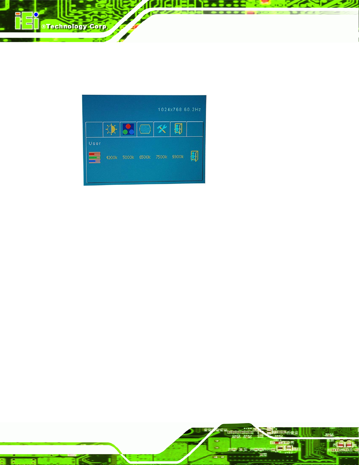
4.1.4.2 User Sub-Menu
The User sub-menu is shown in Figure 4-5.
Figure 4-5: User Sub-Menu
User:
o This item adjusts the balance among Red, Green, and Blue color hues if
images look garish or unrealistic.
Page 47
Page 62

LKM Series Console Drawer
4.1.5 Image Menu
The Image menu is shown in Figure 4-6.
Figure 4-6: Image Menu
The Image menu adjusts the screen position options.
AutoAdjust:
o This item automatically adjusts the screen position.
Width:
o This item adjusts the screen size in the horizontal direction.
Clock Phase:
o This item adjusts the input signal and dot clock position (Analog only).
HPos:
o This item adjusts the horizontal position of the display screen.
VPos:
o This item adjusts the vertical position of the display screen.
Exit:
o This item exits the Image menu.
Page 48
Page 63
LKM Series Console Drawer
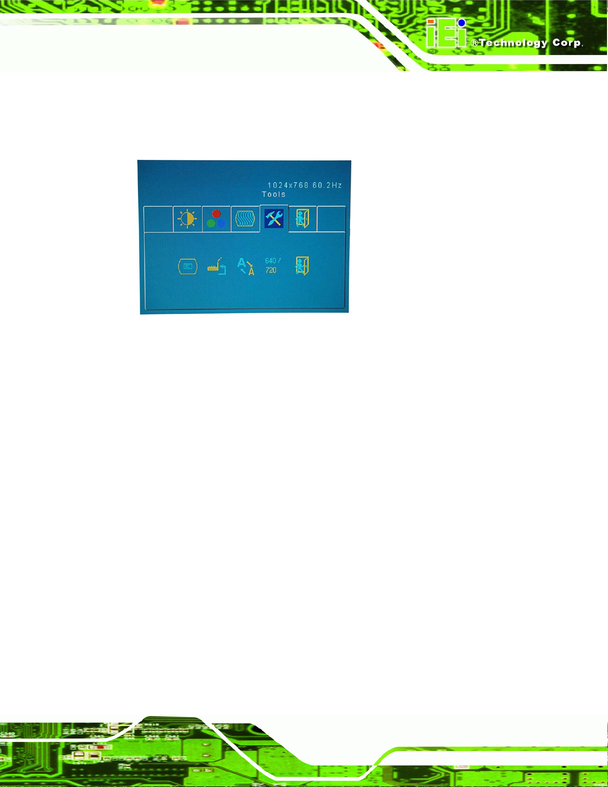
4.1.6 Tools Menu
The Tools menu is shown in Figure 4-7.
Figure 4-7: Tools Menu
The Tools menu has the following options:
OSD:
o This enters the OSD sub-menu (see Section 4.1.6.1).
Factory Reset:
o This item resets all display values to their factory settings.
Sharpness:
o This item adjusts the sharpness level to preset values. This option may
help reducing the softening edges around displayed objects.
Overlapped Mode:
o This item toggles the DOS mode pixel resolution between 640 and 720.
Exit:
o This item exits the Tools menu.
Page 49
Page 64

LKM Series Console Drawer
4.1.6.1 OSD Sub-Menu
The OSD sub-menu is shown in Figure 4-8.
Figure 4-8: OSD Sub-Menu
OSDTimeOut:
o This item adjusts how many seconds the OSD screen stays visible before
it disappears when OSD is left unattended.
OSDHPos:
o This item adjusts the horizontal position of the OSD display screen.
OSDVPos:
o This item adjusts the vertical position of the OSD display screen.
Exit:
o This item exits the OSD sub-menu.
Page 50
Page 65

LKM Series Console Drawer
4.2 LCM Controls (8-Port KVMA Models)
The LCM is used to control the display and switching status of systems connected to the
console.
4.2.1 LCM Buttons
There are three LCD module (LCM) control buttons and one LED (Figure 4-9) on the
keyboard tray of the LKM series console drawers that have eight port connectors.
Figure 4-9: LCM Control Buttons
LED:
o This item indicates that the LCD is either in Auto Scan mode or Edit
mode.
AUTO / EDIT:
o This item initiates an auto-scan sequence for systems connected to the
console and can be used to edit station names.
UP:
o This item scrolls up through available stations and options.
DOWN:
o This item scrolls down through available stations and options.
Page 51
Page 66

LKM Series Console Drawer
4.2.2 LCM Functions
The following sections describe the LCM functions.
4.2.2.1 Manually Switching Stations
When the LKM series console drawer is initially connected to a power source, "Power On"
is displayed on the LCM; afterwards, "Station 001" is displayed indicating that the system
connected to station 1 ports is currently active. Use the "UP" and "Down" button to activate
control over other stations. The station range is from "station 000" to "station 007".
4.2.2.2 Cycling Through Stations
Press the "AUTO/EDIT" button to activate the automatic switching function. Press the
"AUTO/EDIT" button and the console will continuously cycle through all available stations
at an interval of 10 seconds. Press the "AUTO/EDIT" button again to stop the cycling
sequence.
4.2.2.3 Station Name Editing
The station name editing functions allow users to input the name of each co mputer statio n
on the LCM. The maximum number of input characters is 16. The following procedure is
used as an example of how to change “STATION 001” to "ICP ALPHA SERVER".
Available characters for naming are: A to Z, 0 to 9, space and the following symbols: ! " # $
% & / ( ) * + , - . / = < > ? @ [ ] _
Step 1: Switch to "Station 001" on the LCM (see Section 4.2.2.1).
Step 2: Press the "AUTO/EDIT" button for more than 3 seconds, or until a blinking
cursor is seen on the LCM, to enter edit mode.
Step 3: Press the "UP” or “DOWN" button until reaching the character "I".
Step 4: Press the "AUTO/EDIT" button to select the "I" character.
Step 5: Press the "UP” or “DOWN" button until reaching the character "C".
Page 52
Page 67

LKM Series Console Drawer
Step 6: Press the "AUTO/EDIT" button to select the "C" character.
Step 7: Repeat steps 5 and 6 until "ICP ALPHA SERVER" is written on the LCM.
Step 8: Press the "AUTO/EDIT" button for more than 3 seconds, or until the blinking
cursor disappears from the LCM, to exit edit mode. Step 0:
Page 53
Page 68

LKM Series Console Drawer
THIS PAGE IS INTENTIONALLY LEFT BLANK
Page 54
Page 69

LKM Series Console Drawer
Appendix
A
A Safety Precautions
Page 55
Page 70

LKM Series Console Drawer
WARNING:
The precautions outlined in this chapter should be strictly followed.
Failure to follow these precautions may result in permanent damage to
the LKM Series console drawer.
A.1 Safety Precautions
Please follow the safety precautions outlined in the sections that follow:
A.1.1 General Safety Precautions
Please ensure the following safety precautions are adhered to at all times.
Follow the electrostatic precautions outlined below whenever the LKM
Series console drawer is opened.
Make sure the power is turned off and the power cord is disconnected
whenever the LKM Series console drawer is being installed, moved or
modified.
Do not apply voltage levels that exceed the specified voltage range. Doing so
may cause fire and/or an electrical shock.
Electric shocks can occur if the LKM Series console drawer chassis is
opened when the LKM Series console drawer is running.
Do not drop or insert any objects into the ventilation openings of the LKM
Series console drawer.
If considerable amounts of dust, water, or fluids enter the LKM Series
console drawer, turn off the power supply immediately, unplug the power
cord, and contact the LKM Series console drawer vendor.
DO NOT:
o Drop the LKM Series console drawer against a hard surface.
o Strike or exert excessive force onto the LCD panel.
Page 56
o Touch any of the LCD panels with a sharp object
o In a site where the ambient temperature exceeds the rated temperature
Page 71

LKM Series Console Drawer
A.1.2 Anti-static Precautions
WARNING:
Failure to take ESD precautions during the installation of the LKM
Series console drawer may result in permanent damage to the LKM
Series console drawer and severe injury to the user.
Electrostatic discharge (ESD) can cause serious damage to electronic components,
including the LKM Series console drawer. Dry climates are especially susceptible to ESD.
It is therefore critical that whenever the LKM Series console drawer is opened and any of
the electrical components are handled, the following anti-static precautions are strictly
adhered to.
Wear an anti-static wristband: Wearing a simple ant i-static wristband can
help to prevent ESD from damaging any electrical component.
Self-grounding: Before handling any electrical component, touch any
grounded conducting material. During the time the electrical component is
handled, frequently touch any conducting materials that are connected to the
ground.
Use an anti-static pad: When configuring or working with an electrical
component, place it on an antic-static pad. This reduces the possibility of ESD
damage.
Only handle the edges of the electrical component: When handling the
electrical component, hold the electrical component by its edges.
Page 57
Page 72

LKM Series Console Drawer
A.2 Maintenance and Cleaning Precautions
When maintaining or cleaning the LKM Series console drawer, please follow the
guidelines below.
A.2.1 Maintenance and Cleaning
Prior to cleaning any part or component of the LKM Series console drawer, please read
the details below.
Except for the LCD panel, never spray or squirt liquids directly onto any other
components. To clean the LCD panel, gently wipe it with a piece of soft dry
cloth or a slightly moistened cloth.
The interior of the LKM Series console drawer does not require cleaning.
Keep fluids away from the LKM Series console drawer interior .
Be cautious of all small removable components when vacuuming the LKM
Series console drawer.
Turn the LKM Series console drawer off before cleaning the LKM Series
console drawer.
Never drop any objects or liquids through the openings of the LKM Series
console drawer.
Be cautious of any possible allergic reactions to solvents or chemicals used
when cleaning the LKM Series console drawer.
Avoid eating, drinking and smoking within vicinity of the LKM Series console
drawer.
A.2.2 Cleaning Tools
Some components in the LKM Series console drawer may only be cleaned using a
product specifically designed for the purpose. In such case, the product will be explicitly
mentioned in the cleaning tips. Below is a list of items to use when cleaning the LKM
Series console drawer.
Page 58
Cloth – Although paper towels or tissues can be used, a soft, clean piece of
cloth is recommended when cleaning the LKM Series console drawer.
Page 73

LKM Series Console Drawer
Water or rubbing alcohol – A cloth moistened with water or rubbing alcohol
can be used to clean the LKM Series console drawer.
Using solvents – The use of solvents is not recommended when cleaning
the LKM Series console drawer as they may damage the plastic parts.
Vacuum cleaner – Using a vacuum specifically designed for computers is
one of the best methods of cleaning the LKM Series console drawer. Dust
and dirt can restrict the airflow in the LKM Series console drawer and cause
its circuitry to corrode.
Cotton swabs - Cotton swaps moistened with rubbing alcohol or water are
excellent tools for wiping hard to reach areas.
Foam swabs - Whenever possible, it is best to use lint free swabs such as
foam swabs for cleaning.
Page 59
Page 74

LKM Series Console Drawer
THIS PAGE IS INTENTIONALLY LEFT BLANK
Page 60
Page 75

LKM Series Console Drawer
Appendix
B
B Hazardous Materials
Disclosure
Page 61
Page 76

LKM Series Console Drawer
B.1 Hazardous Material Disclosure Table for IPB Products Certified as RoHS Compliant Under 2002/95/EC Without Mercury
The details provided in this appendix are to ensure that the product is compliant with the
Peoples Republic of China (China) RoHS standards. The table below acknowledges the
presences of small quantities of certain materials in the product, and is appli cable to China
RoHS only.
A label will be placed on each product to indicate the estimated “Environmentally Friendly
Use Period” (EFUP). This is an estimate of the number of years that these substances
would “not leak out or undergo abrupt change.” This product may contain replaceable
sub-assemblies/components which have a shorter EFUP such as batteries and lamps.
These components will be separately marked.
Please refer to the table on the next page.
Page 62
Page 77

LKM Series Console Drawer
Toxic or Hazardous Substances and Elements Part Name
Lead
(Pb)
Housing
X X
Display X
Printed Circuit
X
Mercury
(Hg) (Cd)
O O O O
O O O O
O O O
Board
Metal
O X O O O
Fasteners
Cable
X
O O O O
Assembly
Fan Assembly
Power Supply
X X
X
O O O O
O O O O
Cadmium
Hexavalent
Chromium
(CR(VI))
Polybrominated
Biphenyls
(PBB)
O
Polybrominated
Diphenyl Ethers
(PBDE)
X
X
O
X
X
Assemblies
Battery O
O O O O O
O: This toxic or hazardous substance is contained in all of the homogeneous materials for the part is
below the limit requirement in SJ/T11363-2006
X: This toxic or hazardous substance is contained in at least one of the homogeneous materials for this part
is above the limit requirement in SJ/T11363-2006
Page 63
Page 78

LKM Series Console Drawer
此附件旨在确保本产品符合中国 RoHS 标准。以下表格标示此产品中某有毒物质的含量符
合中国 RoHS 标准规定的限量要求。
本产品上会附有”环境友好使用期限”的标签,此期限是估算这些物质”不会有泄漏或突变”的
年限。本产品可能包含有较短的环境友好使用期限的可替换元件,像是电池或灯管,这些元
件将会单独标示出来。
部件名称
壳体
显示
印刷电路板
金属螺帽
电缆组装
风扇组装
电力供应组装
电池
有毒有害物质或元素
铅
(Pb)
X
X
X
X
X
X
汞
(Hg)
O O O O
O O O O
O O O O
O O O O
O O O O
O O O O
O O O X O
O
O O O O O
镉
(Cd)
六价铬
(CR(VI))
多溴联苯
(PBB)
多溴二苯醚
(PBDE)
X
X
X
O
X
X
X
O: 表示该有毒有害物质在该部件所有物质材料中的含量均在 SJ/T11363-2006 标准规定的限量要求以下。
X: 表示该有毒有害物质至少在该部件的某一均质材料中的含量超出 SJ/T11363-2006 标准规定的限量要求。
Page 64
Page 79

LKM Series Console Drawer
C Index
Page 65
Page 80

LKM Series Console Drawer
A
anti-static precautions
VGA................................................ 33
F
anti-static pad.................................. 57
anti-static wristband........................ 57
handling........................................... 57
self-grounding................................. 57
B
Backlight MTBF................................. 14
Benefits................................................. 3
Brightness ........................................... 14
C
Cabling................................................ 39
Certifications .......................................... 12
Chassis ................................................ 14
Color ................................................... 15
Contrast............................................... 14
Features................................................. 3
H
Humidity............................................. 15
I
Input Interface..................................... 14
Installation
Tools................................................. 28
Unpacking.......................................... 26
K
Keyboard............................................. 14
KVMA 8-Port Switch ..........................11
L
D
Dimensions ......................................... 16
LKM-926 .................................. 17, 18
LKM-935 ........................................ 19
E
External Connectors
Audio ................................................ 29
Keyboard......................................... 30
Mouse.............................................. 31
Power .............................................. 32
Page 66
LCD Color .......................................... 14
LCD Type............................................ 14
LCM Controls
LCM Buttons .................................. 51
LCM Controls..................................... 51
LCM Functions................................... 52
Cycling Through Stations ............... 52
Manually Switching Stations.......... 52
Station Name Editing...................... 52
M
Maintenance........................................ 12
Page 81

LKM Series Console Drawer
Max. Resolution.................................. 14
Mechanical Overview................................. 5
LKM-926 Series................................ 5
LKM-935 Series................................ 9
Model Options ...................................... 5
Model Variations........................................ 4
Mounting............................................. 34
O
Operation Temperature ....................... 15
Optional Accessories........................... 28
OSD Controls...................................... 42
Brightness and Contrast Menu........ 44
Buttons............................................ 42
Color Menu..................................... 45
Color T em perature Menu................ 46
Image Menu.................................... 48
OSD Menu...................................... 50
P
Packing List............................................ 28
Power Adapter..................................... 14
24V/48V DC Input.......................... 23
5V/12V AC/DC............................... 21
R
Rack Height ........................................ 14
RoHS................................................... 12
S
Safety Precautions.................................... 56
Shock .................................................. 15
T
Touch Pad............................................ 14
Troubleshooting.................................. 12
Tools Menu ..................................... 49
User Menu....................................... 47
OSD Menu Structure........................... 42
V
Vibration ............................................. 15
V iew Angle.......................................... 14
Page 67
 Loading...