

Page 1
®
KINO-9453 Mini-ITX Motherboard
KINO-9453 Motherboard User Manual
IEI Technology Corp.
MODEL:
KINO-9453
Mini-ITX SBC with Intel
VGA/DVI, Dual GbE, USB 2.0, SATA, PCI and Audio
RoHS Compliant
User Manual
Core2 Duo Processor
Rev. 2.10 – 13 December, 2010
Page I
Page 2

Date Version Changes
13 December, 2010 v2.10 Updated for R21 version (deleted Mini PCI slot)
KINO-9453 Mini-ITX Motherboard
Revision
3 December, 2010 v2.02
13 August, 2009 v2.01 Deleted RAID information
July, 2008 v2.00 -Changed Northbridge chipset from Intel® 945GM to Intel® 945GME
Added COM1 and COM2 location diagram in Section
-Added system fan connector (SYS_FAN1) information
-Added four jumper information:
x AT/ATX power mode select jumpers
x LVDS screen resolution select jumper
x COM3 mode select jumpers
x RS-422/485 terminal resister jumpers
April, 2007 v1.00 Initial Release
4.3.6
Page II
Page 3

KINO-9453 Mini-ITX Motherboard
COPYRIGHT NOTICE
The information in this document is subject to change without prior notice in order to
improve reliability, design and function and does not represent a commitment on the part
of the manufacturer.
In no event will the manufacturer be liable for direct, indirect, special, incidental, or
consequential damages arising out of the use or inability to use the product or
documentation, even if advised of the possibility of such damages.
Copyright
This document contains proprietary information protected by copyright. All rights are
reserved. No part of this manual may be reproduced by any mechanical, electronic, or
other means in any form without prior written permission of the manufacturer.
TRADEMARKS
All registered trademarks and product names mentioned herein are used for identification
purposes only and may be trademarks and/or registered trademarks of their respective
owners.
Page III
Page 4
KINO-9453 Mini-ITX Motherboard
Manual Conventions
WARNING!
Warnings appear where overlooked details may cause damage to the equipment or result
in personal injury. Warnings should be taken seriously. Warnings are easy to recognize.
The word “warning” is written as “WARNING,” both capitalized and bold and is followed by
text. The text is the warning message. A warning message is shown below:
WARNING:
This is an example of a warning message. Failure to adhere to warning
messages may result in permanent damage to the KINO-9453 or
personal injury to the user. Please take warning messages seriously.
CAUTION!
Cautionary messages should also be heeded to help reduce the chance of losing data or
damaging the KINO-9453. Cautions are easy to recognize. The word “caution” is written
as “CAUTION,” both capitalized and bold and is followed. The italicized text is the
cautionary message. A caution message is shown below:
Page IV
Page 5
KINO-9453 Mini-ITX Motherboard
CAUTION:
This is an example of a caution message. Failure to adhere to cautions
messages may result in permanent damage to the KINO-9453. Please
take caution messages seriously.
NOTE:
These messages inform the reader of essential but non-critical information. These
messages should be read carefully as any directions or instructions contained therein can
help avoid making mistakes. Notes are easy to recognize. The word “note” is written as
“NOTE,” both capitalized and bold and is followed by text. The text is the cautionary
message. A note message is shown below:
NOTE:
This is an example of a note message. Notes should always be read.
Notes contain critical information about the KINO-9453. Please take
note messages seriously.
Page V
Page 6
KINO-9453 Mini-ITX Motherboard
Packing List
NOTE:
If any of the components listed in the checklist below are missing,
please do not proceed with the installation. Contact the IEI reseller or
vendor you purchased the KINO-9453 from or contact an IEI sales
representative directly. To contact an IEI sales representative, please
send an email to
The items listed below should all be included in the KINO-9453 package.
1 x KINO-9453 single board computer
1 x IDE cable
1 x SATA power cable
2 x SATA cables
1 x Dual RS-232 cable
1 x I/O shielding
1 x Mini jumper pack
1 x Utility CD
1 x QIG (quick installation guide)
Images of the above items are shown in Chapter 3.
sales@iei.com.tw.
Page VI
Page 7

KINO-9453 Mini-ITX Motherboard
Table of Contents
1 INTRODUCTION..................................................................................................... 1
1.1 INTRODUCTION........................................................................................................... 2
1.1.1 KINO-9453 Benefits........................................................................................... 3
1.1.2 KINO-9453 Features.......................................................................................... 3
1.2 KINO-9453 OVERVIEW ............................................................................................. 3
1.2.1 KINO-9453 Overview Photo.............................................................................. 3
1.2.2 KINO-9453 Peripheral Connectors and Jumpers ............................................. 4
1.2.3 Technical Specifications..................................................................................... 5
2 DETAILED SPECIFICATIONS............................................................................. 8
2.1 OVERVIEW.................................................................................................................. 9
2.2 DIMENSIONS............................................................................................................... 9
2.2.1 Board Dimensions.............................................................................................. 9
2.2.2 External Interface Panel Dimensions.............................................................. 10
2.3 DATA FLOW...............................................................................................................11
2.4 COMPATIBLE PROCESSORS ....................................................................................... 12
2.4.1 Compatible Processor Overview ..................................................................... 12
2.4.2 Supported Processors ...................................................................................... 12
2.5 INTEL
2.5.1 Intel® 945GME Overview................................................................................ 13
2.5.2 Intel® 945GME Memory Support..................................................................... 13
2.5.3 Intel® 945GME Integrated Graphics............................................................... 14
2.5.4 Intel® 945GME Direct Media Interface (DMI)................................................ 15
2.6 INTEL
®
945GME NORTHBRIDGE CHIPSET................................................................ 13
2.5.3.1 Intel® 945GME Analog CRT Support.......................................................15
2.5.3.2 Intel® 945GME LVDS Support................................................................. 15
2.5.3.3 Intel® 945GME SDVO Support ................................................................ 15
®
ICH7-M SOUTHBRIDGE CHIPSET................................................................. 16
2.6.1 Intel® ICH7-M Overview ................................................................................. 16
2.6.2 Intel® ICH7-M Audio Codec ’97 Controller.................................................... 16
2.6.3 Intel® ICH7-M IDE Interface........................................................................... 17
2.6.4 Intel® ICH7-M Low Pin Count (LPC) Interface.............................................. 17
Page VII
Page 8
2.6.5 Intel® ICH7-M PCI Interface...........................................................................18
2.6.6 Intel® ICH7-M Real Time Clock ...................................................................... 18
2.6.7 Intel® ICH7-M SATA Controller ...................................................................... 18
2.6.8 Intel® ICH7-M USB Controller........................................................................ 18
2.7 PCIE BUS COMPONENTS .......................................................................................... 19
2.7.1 PCIe Bus Overview.......................................................................................... 19
2.7.2 Broadcom PCI Express GbE interface............................................................. 19
2.8 LPC BUS COMPONENTS ........................................................................................... 19
2.8.1 LPC Bus Overview........................................................................................... 19
2.8.2 BIOS Chipset.................................................................................................... 20
2.8.3 Super I/O chipset.............................................................................................. 20
2.8.3.1 Super I/O LPC Interface ........................................................................... 21
2.8.3.2 Super I/O 16C550 UARTs........................................................................ 21
2.8.3.3 Super I/O Enhanced Hardware Monitor................................................... 21
KINO-9453 Mini-ITX Motherboard
2.8.3.4 Super I/O Fan Speed Controller................................................................ 21
2.8.3.5 Super I/O Keyboard Controller................................................................. 21
2.9 ENVIRONMENTAL AND POWER SPECIFICATIONS ....................................................... 22
2.9.1 System Monitoring........................................................................................... 22
2.9.2 Operating Temperature and Temperature Control........................................... 23
2.9.3 Power Consumption......................................................................................... 23
3 UNPACKING.......................................................................................................... 24
3.1 ANTI-STATIC PRECAUTIONS...................................................................................... 25
3.2 UNPACKING.............................................................................................................. 25
3.2.1 Unpacking Precautions.................................................................................... 25
3.3 UNPACKING CHECKLIST ........................................................................................... 26
3.3.1 Package Contents............................................................................................. 26
3.3.2 Optional Items.................................................................................................. 27
4 CONNECTOR PINOUTS...................................................................................... 29
4.1 PERIPHERAL INTERFACE CONNECTORS..................................................................... 30
4.1.1 KINO-9453 Layout........................................................................................... 30
4.1.2 Peripheral Interface Connectors ..................................................................... 31
4.1.3 External Interface Panel Connectors............................................................... 32
4.2 INTERNAL PERIPHERAL CONNECTORS ...................................................................... 32
Page VIII
Page 9

KINO-9453 Mini-ITX Motherboard
4.2.1 Fan Connectors................................................................................................ 32
4.2.2 Front Panel Connector.................................................................................... 33
4.2.3 Digital Input/Output Connector....................................................................... 34
4.2.4 IDE Connector................................................................................................. 35
4.2.5 LCD Backlight Connector................................................................................ 37
4.2.6 LVDS LCD connector...................................................................................... 38
4.2.7 Power Connector............................................................................................. 40
4.2.8 14-Pin Serial Port Connectors......................................................................... 41
4.2.9 10-Pin Serial Port Connectors......................................................................... 42
4.2.10 SATA Drive Connectors ................................................................................. 42
4.2.11 SPDIF Connector........................................................................................... 43
4.2.12 Internal USB Connectors............................................................................... 44
4.3 EXTERNAL INTERFACE CONNECTORS....................................................................... 45
4.3.1 Audio Connectors............................................................................................. 46
4.3.2 CRT Connector ................................................................................................ 47
4.3.3 DVI Connector................................................................................................. 47
4.3.4 Ethernet Connectors ........................................................................................ 48
4.3.5 Keyboard/Mouse Connector............................................................................ 50
4.3.6 Serial Port Connectors .................................................................................... 51
4.3.7 USB Connector ................................................................................................ 52
5 INSTALLATION .................................................................................................... 53
5.1 ANTI-STATIC PRECAUTIONS...................................................................................... 54
5.2 INSTALLATION CONSIDERATIONS.............................................................................. 55
5.2.1 Installation Notices.......................................................................................... 55
5.2.2 Installation Checklist....................................................................................... 56
5.3 CPU, CPU COOLING KIT AND DIMM INSTALLATION.............................................. 57
5.3.1 Socket 479 CPU Installation............................................................................ 57
5.3.2 Cooling Kit CF-479B-RS Installation.............................................................. 60
5.3.3 DIMM Installation........................................................................................... 62
5.4 JUMPER SETTINGS .................................................................................................... 63
5.4.1 AT /ATX Power Select Jumper Settings ............................................................ 64
5.4.2 Clear CMOS Jumper........................................................................................ 65
5.4.3 COM 3 Function Select Jumper....................................................................... 67
5.4.4 RS-422 or RS-486 Termination Resister .......................................................... 68
Page IX
Page 10

5.4.5 LVDS Screen Resolution Selection................................................................... 69
5.4.6 LVDS Voltage Selection.................................................................................... 71
5.5 CHASSIS INSTALLATION............................................................................................ 73
5.5.1 Airflow.............................................................................................................. 73
5.5.2 Motherboard Installation................................................................................. 73
5.6 INTERNAL PERIPHERAL DEVICE CONNECTIONS........................................................ 74
5.6.1 Peripheral Device Cables................................................................................ 74
5.6.2 IDE Cable Connection..................................................................................... 74
5.6.3 Dual RS-232 Cable Connection....................................................................... 75
5.6.4 SATA Drive Connection ................................................................................... 76
5.7 EXTERNAL PERIPHERAL INTERFACE CONNECTION................................................... 78
5.7.1 Audio Connection............................................................................................. 78
5.7.2 RJ-45 Ethernet Connection..............................................................................79
5.7.3 USB Connection...............................................................................................80
KINO-9453 Mini-ITX Motherboard
5.7.4 VGA Monitor Connection ................................................................................ 81
5.7.5 Serial Device Connection ................................................................................ 82
5.7.6 PS/2 Keyboard/Mouse Connection.................................................................. 83
6 AMI BIOS................................................................................................................ 85
6.1 INTRODUCTION......................................................................................................... 86
6.1.1 Starting Setup................................................................................................... 86
6.1.2 Using Setup...................................................................................................... 86
6.1.3 Getting Help.....................................................................................................87
6.1.4 Unable to Reboot After Configuration Changes.............................................. 87
6.1.5 BIOS Menu Bar................................................................................................ 87
6.2 MAIN........................................................................................................................ 88
6.3 ADVANCED............................................................................................................... 89
6.3.1 CPU Configuration.......................................................................................... 90
6.3.2 IDE Configuration........................................................................................... 91
6.3.2.1 IDE Master, IDE Slave............................................................................. 94
6.3.3 Super IO Configuration ................................................................................... 98
6.3.4 Hardware Health Configuration.................................................................... 102
6.3.5 ACPI Configuration....................................................................................... 107
6.3.5.1 General ACPI Configuration...................................................................107
6.3.6 APM Configuration........................................................................................ 109
Page X
Page 11

KINO-9453 Mini-ITX Motherboard
6.3.7 Remote Access Configuration.........................................................................111
6.3.8 USB Configuration..........................................................................................115
6.3.8.1 USB Mass Storage Device Configuration................................................118
6.4 PCI/PNP................................................................................................................. 120
6.5 BOOT...................................................................................................................... 126
6.5.1 Boot Settings Configuration........................................................................... 127
6.5.2 Boot Device Priority...................................................................................... 129
6.5.3 Removable Drives.......................................................................................... 131
6.6 SECURITY............................................................................................................... 132
6.7 CHIPSET ................................................................................................................. 133
6.7.1 NorthBridge Configuration............................................................................ 134
6.7.1.1 V ideo Function Configuration ................................................................ 135
6.7.2 SouthBridge Chipset Configuration............................................................... 138
6.8 EXIT....................................................................................................................... 140
7 DRIVER INSTALLATION.................................................................................. 142
7.1 AVAILABLE SOFTWARE DRIVERS............................................................................ 143
7.2 DRIVER CD AUTO-RUN.......................................................................................... 143
7.3 CHIPSET DRIVER INSTALLATION............................................................................. 144
7.4 INTEL GRAPHICS MEDIA ACCELERATOR DRIVER....................................................149
7.5 BROADCOM LAN DRIVER (FOR GBE LAN) INSTALLATION ................................... 155
7.6 REALTEK AC`97 AUDIO DRIVER (ALC655) INSTALLATION................................... 161
7.6.1 BIOS Setup..................................................................................................... 161
7.6.2 Driver Installation ......................................................................................... 161
A BIOS OPTIONS.................................................................................................... 167
B DIO INTERFACE................................................................................................. 171
B.1 DIO INTERFACE INTRODUCTION............................................................................ 172
B.2 DIO CONNECTOR PINOUTS.................................................................................... 172
B.3 ASSEMBLY LANGUAGE SAMPLES........................................................................... 173
B.3.1 Enable the DIO Input Function..................................................................... 173
B.3.2 Enable the DIO Output Function.................................................................. 173
C WATCHDOG TIMER.......................................................................................... 174
Page XI
Page 12
KINO-9453 Mini-ITX Motherboard
List of Figures
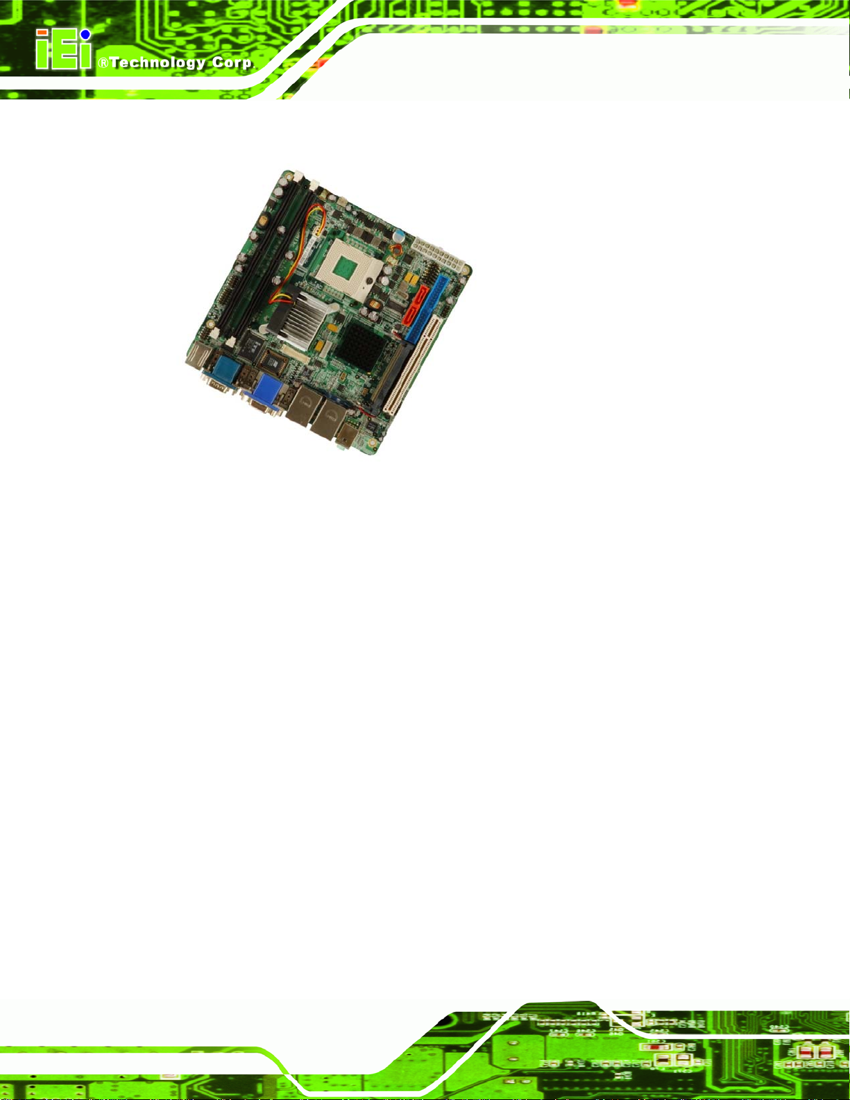
Figure 1-1: KINO-9453 Embedded SBC........................................................................................2
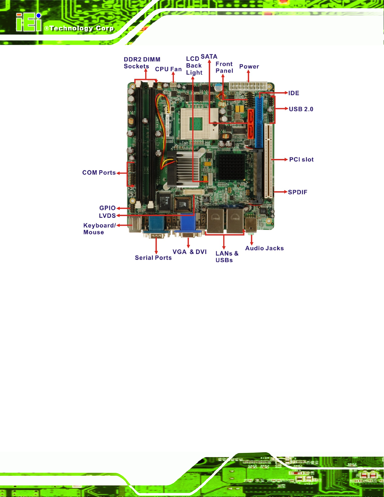
Figure 1-2: KINO-9453 Overview...................................................................................................4
Figure 2-1: KINO-9453 Dimensions (mm).....................................................................................9
Figure 2-2: External Interface Panel Dimensions (mm)............................................................10
Figure 2-3: Data Flow Block Diagram.........................................................................................11
Figure 2-4: 240-pin DIMM Sockets..............................................................................................14
Figure 4-1: Connector and Jumper Locations...........................................................................30
Figure 4-2: Fan Connector Locations.........................................................................................33
Figure 4-3: Front Panel Connector Location .............................................................................34
Figure 4-4: GPIO Connector Location........................................................................................35
Figure 4-5: IDE Device Connector Location ..............................................................................36
Figure 4-6: LCD Backlight Connector Location ........................................................................38
Figure 4-7: LVDS LCD Connector Location ...............................................................................39
Figure 4-8: Power Connector Location ......................................................................................40
Figure 4-9: 14-Pin Serial Port Connector Locations.................................................................41
Figure 4-10: 10-Pin Serial Port Connector Locations...............................................................42
Figure 4-11: SATA Drive Connector Locations ..........................................................................43
Figure 4-12: SPDIF Connector Locations ..................................................................................44
Figure 4-13: Internal USB Connector Locations .......................................................................45
Figure 4-14: KINO-9453 External Interface Connectors............................................................46
Figure 4-15: Audio Connectors...................................................................................................46
Figure 4-16: VGA Connector........................................................................................................47
Figure 4-17 DVI-I Connector Pinout Locations..........................................................................48
Figure 4-18: RJ-45 Ethernet Connector......................................................................................49
Figure 4-19: PS/2 Pinouts ............................................................................................................50
Figure 4-20: External Serial Port Connector..............................................................................51
Figure 5-1: Make sure the CPU socket retention screw is unlocked ......................................58
Figure 5-2: Lock the CPU Socket Retention Screw...................................................................59
Figure 5-3: IEI CF-479B-RS Cooling Kit......................................................................................60
Figure 5-4: Cooling Kit Support Bracket....................................................................................61
Figure 5-5: Connect the cooling fan cable.................................................................................61
Page XII
Page 13

KINO-9453 Mini-ITX Motherboard
Figure 5-6: Installing a DIMM.......................................................................................................62
Figure 5-7: Jumper Locations.....................................................................................................63
Figure 5-8: AT/ATX Power Select Jumper Location ..................................................................65
Figure 5-9: Clear CMOS Jumper .................................................................................................66
Figure 5-10: COM 3 Function Select Jumper Locations...........................................................68
Figure 5-11: RS-422 and RS-485 Termination Resister Jumper Locations.............................69
Figure 5-12: LVDS Screen Resolution Selection Jumper Pinout Locations...........................71
Figure 5-13: LVDS Voltage Selection Jumper Pinout Locations..............................................72
Figure 5-14: IDE Cable Connection.............................................................................................75
Figure 5-15: Dual RS-232 Cable Installation..............................................................................76
Figure 5-16: SATA Drive Cable Connection ...............................................................................77
Figure 5-17: SATA Power Drive Connection ..............................................................................77
Figure 5-18: Audio Connectors...................................................................................................79
Figure 5-19: RJ-45 Ethernet Connector......................................................................................80
Figure 5-20: USB Connector........................................................................................................81
Figure 5-21: VGA Connector........................................................................................................82
Figure 5-22: Serial Device Connector.........................................................................................83
Figure 5-23: PS/2 Keyboard/Mouse Connector.........................................................................84
Figure 6-1: Video Function Configuration............................................................................... 136
Figure 7-1: Available Drivers .................................................................................................... 144
Figure 7-2: Chipset Driver Installation Program..................................................................... 145
Figure 7-3: Chipset Driver Installation Welcome Screen....................................................... 146
Figure 7-4: Chipset Driver Installation License Agreement.................................................. 147
Figure 7-5: Chipset Driver Readme File Information ............................................................. 148
Figure 7-6: Chipset Driver Installation Complete................................................................... 149
Figure 7-7: Select the Operating System ................................................................................ 150
Figure 7-8: VGA Driver.............................................................................................................. 151
Figure 7-9: GMA Driver Readme File....................................................................................... 152
Figure 7-10: GMA Driver File Extraction.................................................................................. 152
Figure 7-11: GMA Driver Installation Welcome Screen.......................................................... 153
Figure 7-12: GMA Driver License Agreement ......................................................................... 154
Figure 7-13: GMA Driver Installing Notice............................................................................... 154
Figure 7-14: GMA Driver Installation Complete...................................................................... 155
Figure 7-15: Access Windows Control Panel ......................................................................... 156
Figure 7-16: Double Click the System Icon............................................................................. 157
Page XIII
Page 14

Figure 7-17: Double Click the Device Manager T ab............................................................... 157
Figure 7-18: Device Manager List ............................................................................................ 158
Figure 7-19: Search for Suitable Driver................................................................................... 159
Figure 7-20: Locate Driver Files............................................................................................... 160
Figure 7-21: Location Browsing Window................................................................................ 160
Figure 7-22: AC`97 Audio Driver Install Shield Wizard Starting............................................ 161
Figure 7-23: AC`97 Audio Driver Setup Preparation .............................................................. 162
Figure 7-24: AC`97 Audio Driver Welcome Screen................................................................. 162
Figure 7-25: AC`97 Audio Driver Software Configuration ..................................................... 163
Figure 7-26: AC`97 Audio Driver Digital Signal....................................................................... 164
Figure 7-27: AC`97 Audio Driver Installation Begins ............................................................. 165
Figure 7-28: AC`97 Audio Driver Installation Complete......................................................... 166
KINO-9453 Mini-ITX Motherboard
Page XIV
Page 15

KINO-9453 Mini-ITX Motherboard
List of Tables
Table 1-1: Technical Specifications ..............................................................................................7
Table 2-1: Processor Features ....................................................................................................12
Table 2-2: Supported Processors ...............................................................................................13
Table 2-3: Supported HDD Specifications..................................................................................17
Table 2-4: Power Consumption...................................................................................................23
Table 2-5: Power Consumption...................................................................................................23
Table 3-1: Package List Contents................................................................................................27
Table 3-2: Optional Items .............................................................................................................28
Table 4-1: Peripheral Interface Connectors ...............................................................................31
Table 4-2: Rear Panel Connectors ..............................................................................................32
Table 4-3: Fan Connector Pinouts...............................................................................................33
Table 4-4: Front Panel Connector Pinouts.................................................................................34
Table 4-5: GPIO Connector Pinouts............................................................................................35
Table 4-6: IDE Connector Pinouts...............................................................................................37
Table 4-7: LCD Backlight Connector Pinouts............................................................................38
Table 4-8: LVDS LCD Connector Pinouts...................................................................................39
Table 4-9: Power Connector Pinouts..........................................................................................40
Table 4-10: COM2 Pinouts............................................................................................................41
Table 4-11: COM4 Pinouts............................................................................................................42
Table 4-12: SATA Drive Connector Pinouts................................................................................43
Table 4-13: SPDIF Pinouts ...........................................................................................................44
Table 4-14: USB3 and USB4 Pinouts ..........................................................................................45
Table 4-15: VGA Connector Pinouts...........................................................................................47
Table 4-16: DVI-I Connector Pinouts...........................................................................................48
Table 4-17: LAN1 and LAN2 Pinouts...........................................................................................49
Table 4-18: RJ-45 Ethernet Connector LEDs .............................................................................49
Table 4-19: PS/2 Connector Pinouts...........................................................................................50
Table 4-20: External Serial Port Pinouts.....................................................................................51
Table 4-21: External USB Connector Pinouts............................................................................52
Table 5-1: Jumpers .......................................................................................................................64
Page XV
Page 16

Table 5-2: AT/ATX Power Select Jumper Settings.....................................................................64
Table 5-3: Clear CMOS Jumper Settings....................................................................................66
Table 5-4: COM 3 Function Select Jumper Settings .................................................................67
T able 5-5: RS-422 Termination Resister Jumper Settings........................................................68
T able 5-6: RS-485 Termination Resister Jumper Settings........................................................69
Table 5-7: LVDS Screen Resolution Selection Jumper Settings..............................................70
Table 5-8: LVDS Voltage Selection Jumper Settings.................................................................72
Table 5-9: IEI Provided Cables ....................................................................................................74
Table 6-1: BIOS Navigation Keys ................................................................................................87
KINO-9453 Mini-ITX Motherboard
Page XVI
Page 17
KINO-9453 Mini-ITX Motherboard
BIOS Menus
Menu 1: Main.................................................................................................................................88
Menu 2: Advanced........................................................................................................................90
Menu 3: CPU Configuration.........................................................................................................91
Menu 4: IDE Configuration...........................................................................................................92
Menu 5: IDE Master and IDE Slave Configuration.....................................................................94
Menu 6: Super IO Configuration .................................................................................................99
Menu 7: Hardware Health Configuration................................................................................. 102
Menu 8: ACPI Configuration..................................................................................................... 107
Menu 9: General ACPI Configuration [Advanced\ ACPI Configuration] .............................. 108
Menu 10:Advanced Power Management Configuration........................................................ 109
Menu 11: Remote Access Configuration [Advanced].............................................................112
Menu 12: USB Configuration.....................................................................................................116
Menu 13: USB Mass Storage Device Configuration................................................................118
Menu 14: PCI/PnP Configuration ............................................................................................. 121
Menu 15: Boot............................................................................................................................ 126
Menu 16: Boot Settings Configuration.................................................................................... 127
Menu 17: Boot Device Priority Settings .................................................................................. 130
Menu 18: Removable Drives.....................................................................................................131
Menu 19: Security...................................................................................................................... 132
Menu 20: Chipset....................................................................................................................... 133
Menu 21:NorthBridge Chipset Configuration......................................................................... 134
Menu 22:SouthBridge Chipset Configuration......................................................................... 138
Menu 23:Exit............................................................................................................................... 140
Page XVII
Page 18
KINO-9453 Mini-ITX Motherboard
Chapter
1
1 Introduction
Page 1
Page 19
1.1 Introduction
KINO-9453 Mini-ITX Motherboard
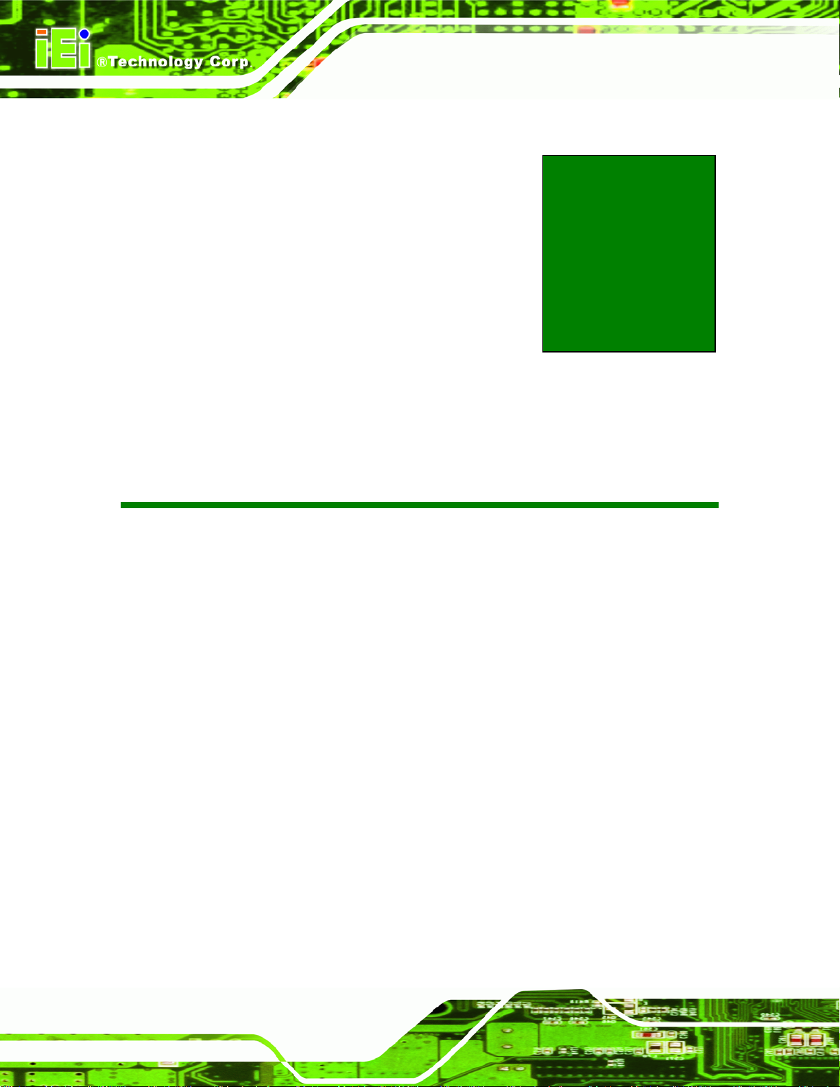
Figure 1-1: KINO-9453 Embedded SBC
The KINO-9453 Mini-ITX form factor motherboard is an Intel® dual-core CPU platform.
Intel® Core™2 Duo, Core Duo and Core Solo CPU are all supported to enhance the
system processing speed. The KINO-9452 has a maximum front side bus (FSB)
frequency of 667 MHz and contains two DDR2 SDRAM DIMM sockets that support up to
4 GB system memory.
The KINO-9453 supports diverse displays including on e VGA display , one DVI display and
one LVDS display. These multimedia features make the KINO-9453 a best choice for
integrating into point-of-sale (POS), kiosk or digital signage applications.
The KINO-9453 supports up to two serial ATA (SATA) hard disk drives (HDD) with
maximum transfer rates of 1.5 Gb/s and up to eight USB 2.0 devices. The dual PCI
Express (PCIe) Gigabit Ethernet (GbE) controllers provide GbE connectivity for network
communication. The KINO-9453 also has a PCI socket for system expansion. Three
Page 2
RS-232, one RS-232/422/485 and one digital input/output (DIO) port offer system
integrators more choices of peripheral devices for the t argeted application.
Page 20
KINO-9453 Mini-ITX Motherboard
1.1.1 KINO-9453 Benefits
Some of the KINO-9453 benefits are listed below:
Multiple display output options
Storage flexibility with support for SATA drives and IDE drives
Expandable system with PCI slot
DDR2 support enables faster data transfers
Multiple I/O interfaces provide connectivity to a broad range of external
peripheral devices
1.1.2 KINO-9453 Features
Some of the KINO-9453 features are listed below.
Support for Socket 479 Intel
Maximum FSB of 667 MHz
Supports two 240-pin 400 MHz, 533 MHz or 667 MHz 2GB DDR2 DIMM
memory modules
Two SATA drives with transfer rates of 1.5 Gb/s supported
Two Ultra ATA 100, Ultra ATA 66 or Ultra ATA 33 IDE HDDs supported
Eight USB 2.0 devices supported
Dual PCIe GbE Ethernet connectivity
Multiple display options including CRT, DVI and dual-channel LVDS
Mini-ITX form factor
RoHS compliant
Supports AT and ATX power supplies
1.2 KINO-9453 Overview
1.2.1 KINO-9453 Overview Photo
®
Core 2 Duo or Core Solo CPUs
The KINO-9453 has a wide variety of internal and external peripheral connectors. The
peripheral connectors are connected to devices including PCI devices, storage devices,
display devices and serial communications devices. A labeled photo of the peripheral
connectors on the front of the KINO-9453 is shown in
Figure 1-2.
Page 3
Page 21
KINO-9453 Mini-ITX Motherboard
Figure 1-2: KINO-9453 Overview
1.2.2 KINO-9453 Peripheral Connectors and Jumpers
The KINO-9453 has the following connectors on-board:
2 x DDR2 DIMM sockets
1 x Digital I/O connector
3 x Fan connectors
1 x Front panel connector
1 x IDE Interface connector
1 x LCD backlight connector
1 x LVDS LCD connector
1 x PCI slot
1 x Power connector
Page 4
Page 22
KINO-9453 Mini-ITX Motherboard
2 x Serial port connectors
2 x SATA connectors
1 x SPDIF connector
2 x USB connectors
The KINO-9453 has the following external peripheral interface connectors on the board
rear panel
2 x Audio jacks
1 x VGA connector
2 x Ethernet connectors
2 x Keyboard/Mouse connectors
2 x Serial port connectors
1 x DVI connector
4 x USB 2.0 ports
The KINO-9453 has the following on-board jumpers:
AT/ATX power mode selection
Clear CMOS
COM3 mode selection (RS-232/422/485)
RS-422 or RS-485 termination resister
LVDS LCD voltage selection
L VDS screen resolution selection
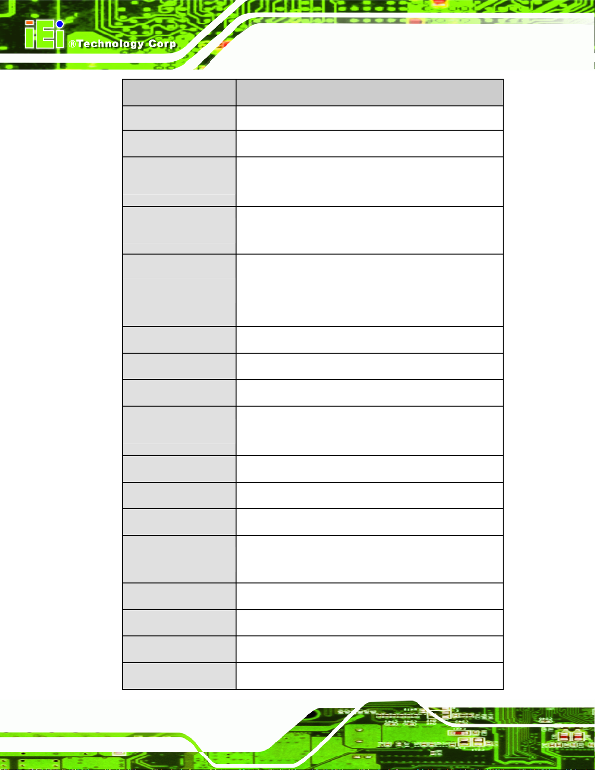
1.2.3 Technical Specifications
KINO-9453 technical specifications are listed in Table 1-1. See Chapter 2 for details.
Specification KINO-9453
Form Factor
Mini-ITX
Socket 479 Intel® Core™ 2 Duo Mobile
System CPU
Socket 479 Intel® Core™ Duo
Socket 479 Intel® Core™ Solo
Page 5
Page 23
KINO-9453 Mini-ITX Motherboard
Specification KINO-9453
Socket 479 Intel
®
Celeron® M FSB 533 MHz (socket M)
Front Side Bus
System Chipset
Memory
Display
BIOS
Audio
LAN
COM
533 MHz or 667 MHz
Northbridge: Intel® 945GME
Southbridge: Intel® ICH7-M
Two 240-pin 400 MHz, 53 3 MHz or 667 MHz DDR2 SDRAM
DIMMs supported (system max. 4 GB)
CRT: Integrated in the Intel® 945GME to support CRT
DVI: Integrated in the Intel® 945GME by SDVO interface
LVDS: Dual channel 18-bit or 24 -bit LVDS LCD panel
AMI BIOS
Realtek ALC655 with AC’97 codec
Two Broadcom BCM578 7M PCIe GbE controllers
Three RS-232 serial ports (one internal, two external)
One RS-232, RS-422 or RS-485 serial port
Page 6
USB2.0
IDE
SATA
Keyboard/mouse
Watchdog Timer
Power Supply
Temperature
Humidity (operating)
Eight USB 2.0 devices supported
One 40-pin IDE connects to two Ultra ATA33/66/100 devices
Two 1.5 Gb/s SATA drives supported
Two PS/2 connectors support mouse and keyboard
connectivity
Software programmable 1-255 sec. by super I/O
AT and ATX supported
0ºC – 60ºC (32ºF - 140ºF)
5%~95% non-condensing
Page 24
KINO-9453 Mini-ITX Motherboard
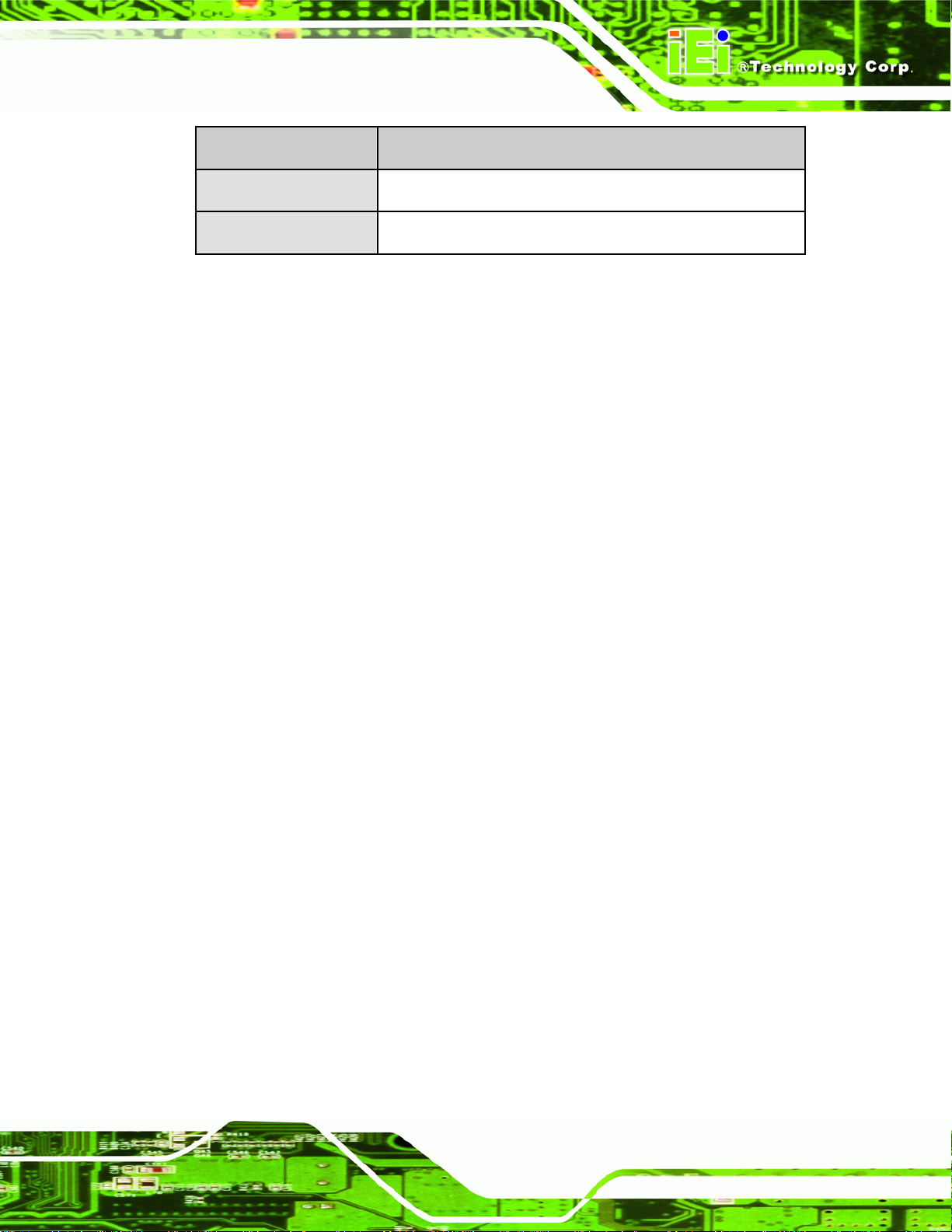
Specification KINO-9453
Dimensions (LxW)
Weight (GW/NW)
Table 1-1: Technical Specifications
170 mm x 170 mm
900g/ 362g
Page 7
Page 25
KINO-9453 Mini-ITX Motherboard
Chapter
2
2 Detailed Specifications
Page 8
Page 26
KINO-9453 Mini-ITX Motherboard
2.1 Overview
This chapter describes the specifications and on-board features of the KINO-9453 in
detail.
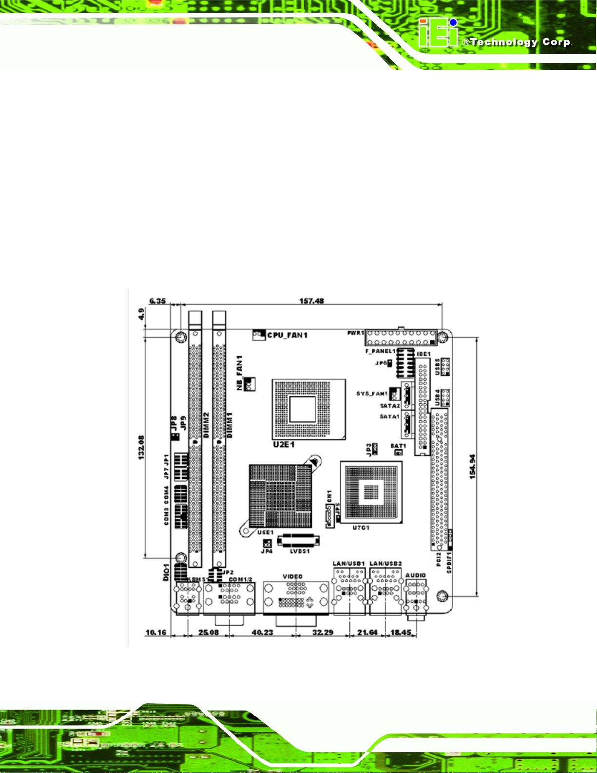
2.2 Dimensions
2.2.1 Board Dimensions
The dimensions of the board are listed below:
Length: 170 mm
Width: 170 mm
Figure 2-1: KINO-9453 Dimensions (mm)
Page 9
Page 27
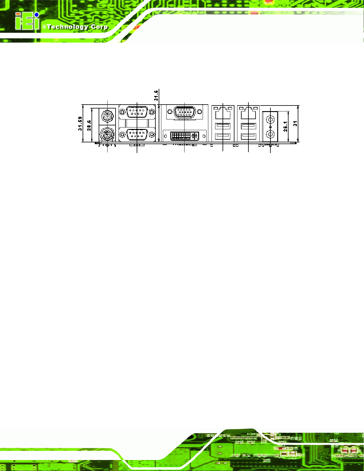
2.2.2 External Interface Panel Dimensions
External peripheral interface connector panel dimensions are shown in Figure 2-2.
Figure 2-2: External Interface Panel Dimensions (mm)
KINO-9453 Mini-ITX Motherboard
Page 10
Page 28
KINO-9453 Mini-ITX Motherboard
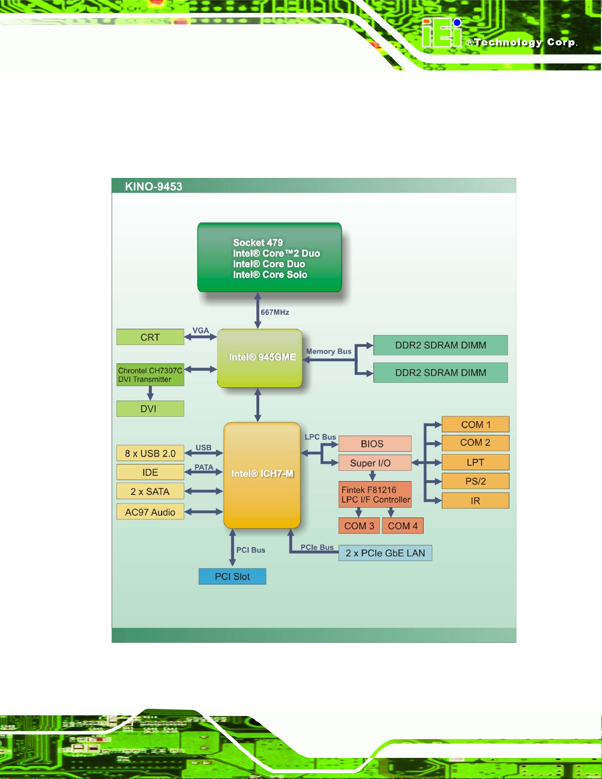
2.3 Data Flow
Figure 2-3 shows the data flow between the two on-board chip set s and other component s
installed on the motherboard and described in the followin g sections of this chapter.
Figure 2-3: Data Flow Block Diagram
Page 11
Page 29
2.4 Compatible Processors
2.4.1 Compatible Processor Overview
The KINO-9453 supports the following socket 479 proce ssors:
KINO-9453 Mini-ITX Motherboard
Intel
Intel
Intel
Intel® Celeron® M processors
®
Core™2 Duo Mobile processors
®
Core™ Duo processors
®
Core™ Solo processors
The first three of the above processors communicate with the Intel® 945GME GMCH
through a 667 MHz FSB and the Intel® Celeron® M processor through a 533 MHz FSB.
Features of the supported processors are listed in
Table 2-1.
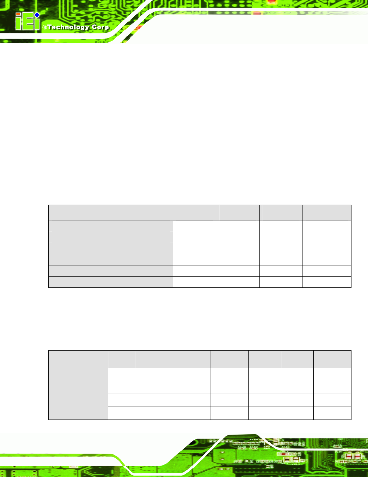
CPU Features Core™2 Duo Core™ Duo Core™ Solo Celeron® M
Dual core Yes Yes No No
Enhanced Halt State (C1E) No Yes No No
Enhanced Intel® Speedstep® Technolgy
Execute Disable Bit Yes Yes Yes Yes
Intel® EM64T
Intel® Virtualization Technology
Yes Yes Yes No
Yes No No No
Yes Yes No No
Table 2-1: Processor Features
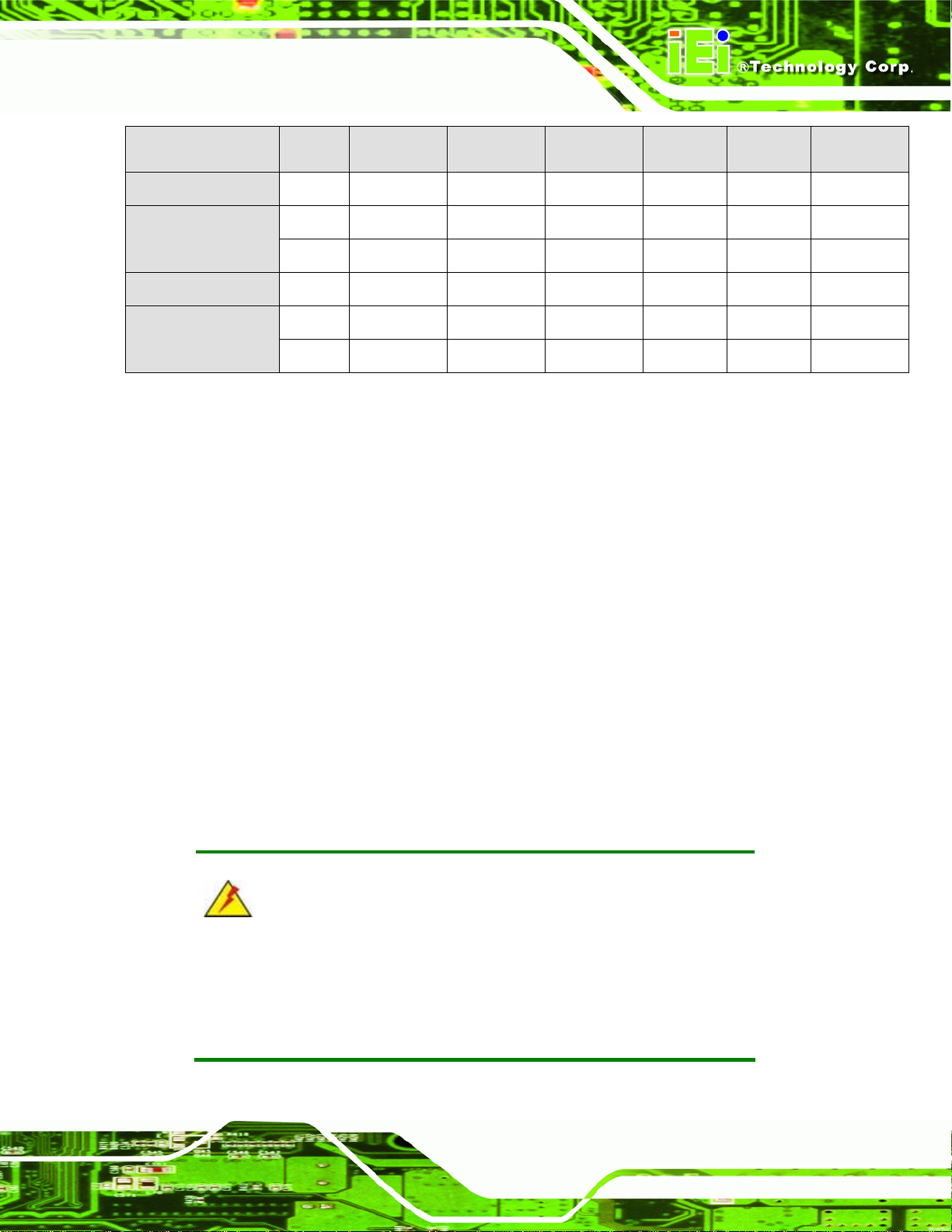
2.4.2 Supported Processors
Specifications for the compatible processors are listed in Table 2-2 below:
Family sSpec# CPU Speed Processor # Bus Speed Mfg Tech Stepping Cache Size
Core™2 Duo Mobile
Page 12
SL9SJ 2.33 GHz T7600 667 MHz 65 nm B2 4 MB
SL9SK 2.16 GHz T7400 667 MHz 65 nm B2 4 MB
SL9SL 2 GHz T7200 667 MHz 65 nm B2 4 MB
SL9SP 1.83 GHz T5600 667 MHz 65 nm B2 2 MB
Page 30
KINO-9453 Mini-ITX Motherboard
Family sSpec# CPU Speed Processor # Bus Speed Mfg Tech Stepping Cache Size
SL9SQ 1.66 GHz T5500 667 MHz 65 nm B2 2 MB
SL8VT 2 GHz T2500 667 MHz 65 nm C0 2 MB Core™ Duo
SL9DN 1.66 GHz T2300E 667 MHz 65 nm C0 2 MB
Core™ Solo SL92X 1.83 GHz T1400 667 MHz 65 nm C0 2 MB
Celeron® M
SL9VA 1.73 GHz 530 533 MHz 65 nm A1 1 MB
SL9LF 1.86 GHz 440 533 MHz 65 nm D0 1 MB
Table 2-2: Supported Processors
2.5 Intel® 945GME Northbridge Chipset
2.5.1 Intel® 945GME Overview
The Intel® 945GME Northbridge chipset has the Generation 3.1 Intel Integrated Graphics
Engine and the Intel
graphics and memory controller hub (GMCH) facilitates the flow of information primarily
between the following four interfaces:
Front Side Bus (FSB)
System Memory Interface
Graphics Interface
Direct Media Interface (DMI)
®
Graphics Media Accelerator 950 (Intel® GMA 950). The integrated
2.5.2 Intel® 945GME Memory Support
WARNING:
Only DDR2 memory module can be installed on the KINO-9453. Do not
install DDR memory modules. If a DDR memory module is installed on
the KINO-9453, the KINO-9453 may be irreparably damaged.
Page 13
Page 31

KINO-9453 Mini-ITX Motherboard
The Intel® 945GME Northbridge chipset on the KINO-9453 supports two DDR2 240-pin
DIMMs with the following features:
Two 240-pin DIMMs
DDR2 only (DO NOT install a DDR DIMM)
Single-channel or dual-channel
Capacities of 256 MB, 512 MB, 1 GB or 2 GB
Transfer speeds of 400 MH z, 533 MHz, or 667 MHz
The memory sockets are shown in
Figure 2-4.
Figure 2-4: 240-pin DIMM Sockets
2.5.3 Intel® 945GME Integrated Graphics
Page 14
The Intel® 945GME Northbridge chipset has an Intel® Gen. 3.5 integrated graphics engine
that supports the following display devices:
Analog CRT
LVDS
S-DVO interface (DVI connector)
Page 32

KINO-9453 Mini-ITX Motherboard
2.5.3.1 Intel® 945GME Analog CRT Support
A DB-15 VGA connector on the external peripheral interface connector panel is interfaced
to the Intel
an integrated 400 MHz RAMDAC and hot plug CRT support, supports analog CRT
monitors up to QXGA.
®
945GME graphics engine. The Intel® 945GME internal graphics engine, with
2.5.3.2 Intel® 945GME LVDS Support
A 30-pin LVDS crimp connector is interfaced to the Intel® 945GME graphics engine. The
®
Intel
945GME internal graphics engine supports LVDS displays with the following
features:
Up to UXGA monitors with a maximum resolution of 1600 x 1200
18-bit or 24-bit 25 MHz to 112 MHz single-channel or dual-channel LVDS
screens
CPIS 1.5 compliant LVDS screens
2.5.3.3 Intel® 945GME SDVO Support
The Intel® 945GME internal graphics engine has the following SDVO output features:
Concurrent operation of PCIe x1 with SDVO
Two SDVO p orts supported
o SDVO is muxed onto the PCIe pins
o DVI 1.0 support for external digital monitor
o Only Downstream HDCP support
o Display hot plug support
2.5.4 Intel® 945GME Direct Media Interface (DMI)
Intel® 945GME Northbridge GMCH is connected to the Intel® ICH7-M Southbridge Chipset
through the chip-to-chip Direct Media Interface (DMI). Features of the Intel
®
945GME DMI
are listed below:
2 GB/s (1 GB/s in each direction) bus speed
32-bit downstream address
Page 15
Page 33

KINO-9453 Mini-ITX Motherboard
2.6 Intel® ICH7-M Southbridge Chipset
2.6.1 Intel® ICH7-M Overview
The Intel® ICH7-M Southbridge chipset is connected to the Intel® 945GME Northbridge
GMCH through the chip-to-chip Direct Media Interface (DMI). Some of the features of the
®
Intel
ICH7-M are listed below.
Complies with PCI Express Base Sp ecification, Revision 1.0a
Complies with PCI Local Bus S pecificati on, Revision 2.3 and su pp orts 33MHz
PCI operations
Supports ACPI Power Management Logic
Contains:
o Enhanced DMA controller
o Interrupt controller
o Timer functions
Integrated SATA host controller with DMA operations interfaced to two SATA
connectors on the KINO-9453
Integrated IDE controller supports Ultra ATA 100/66/33
Supports the six USB 2.0 devices on the KINO-9453 with four UHCI
controllers and one EHCI controller
Complies with System Management Bus (SMBus) Specification, Version 2.0
Supports Audio Codec ’97 (AC’97) Revision 2.3
Supports Intel
Contains Low Pin Count (LPC) interface
Supports Firmware Hub (FWH) interface
2.6.2 Intel® ICH7-M Audio Codec ’97 Controller
The KINO-9453 has an integrated Realtek ALC65 5 codec. The ALC655 codec is a 16-bit,
full-duplex AC'97 Rev. 2.3 compatible six-channel audio codec designed for PC
®
High Definition Audio
Page 16
multimedia systems, including host/soft audio and AMR/CNR-based designs. Complete
surround sound requires six-channel audio consi sting of:
Front left
Page 34

KINO-9453 Mini-ITX Motherboard
Front right
Back left
Back right
Center
Subwoofer
2.6.3 Intel® ICH7-M IDE Interface
The integrated IDE interface on the ICH7-M Southbridge supports two IDE hard disks and
ATAPI devices. PIO IDE transfers up to 16 MB/s and Ultra ATA tran sfers of 100 MB/s. The
integrated IDE interface is able to support the following IDE HDDs:
Ultra A T A/10 0, with data transfer rates up to 100 MB/s
Ultra A T A/66, with data transfer rates up to 66 MB/s
Ultra A T A/33, with data transfer rates up to 33 MB/s
Specification Ultra A T A/10 0 Ultra AT A/66 Ultra A TA/100
IDE devices
PIO Mode
PIO Max Transfer Rate
DMA/UDMA designation
DMA/UDMA Max Transfer
Controller Interface
2 2 2
0 – 4 0 – 4 0 – 4
16.6 MB/s 16.6 MB/s 16.6 MB/s
UDMA 3 - 4 UDMA 3 – 4 UDMA 2
100 MB/s 66 MB/s 33 MB/s
5V 5V 5V
Table 2-3: Supported HDD Specifications
2.6.4 Intel® ICH7-M Low Pin Count (LPC) Interface
The ICH7-M LPC interface complies with the LPC 1.1 specifications. The LPC bus from
the ICH7-M is connected to the following components:
BIOS chipset
Super I/O chipset
Page 17
Page 35

2.6.5 Intel® ICH7-M PCI Interface
The PCI interface on the ICH7-M is compliant with the PCI Revision 2.3 implementation.
Some of the features of the PCI interface are listed below.
PCI Revision 2.3 compliant
33 MHz
5 V tolerant PCI signals (except PME#)
Integrated PCI arbiter supports up to seven PCI bus masters
2.6.6 Intel® ICH7-M Real Time Clock
256 bytes of battery backed RAM is provided by the Motorola MC146818A real time clock
(RTC) integrated into the ICH7-M. The RTC operates on a 3V battery and 32.768 KHz
crystal. The RTC keeps track of the time and stores system data even when the system is
KINO-9453 Mini-ITX Motherboard
turned off.
2.6.7 Intel® ICH7-M SATA Controller
The integrated SATA controller on the ICH7-M Southbridge supports two SATA drives on
the KINO-9453 with independent DMA operatio ns. SAT A controller specifications are listed
below.
Supports two SATA drives
Supports 1.5 Gb/s data transfer speeds
Supports Serial ATA Specification, Revision 1.0a
2.6.8 Intel® ICH7-M USB Controller
Up to eight high-speed, full-speed or low-speed USB devices are supported by the
ICH7-M on the KINO-9453. High-speed USB 2.0, with data transfers of up to 480 MB/s, is
enabled with the ICH7-M integrated Enhanced Host Controller Interface (EHCI) compliant
host controller. USB full-speed and low-speed signaling is supported by the ICH7-M
Page 18
integrated Universal Host Controller Interface (UHCI) controllers.
Page 36

KINO-9453 Mini-ITX Motherboard
2.7 PCIe Bus Components
2.7.1 PCIe Bus Overview
The PCIe bus is connected to components listed below:
Two PCIe GbE Broadcom LAN controllers
2.7.2 Broadcom PCI Express GbE interface
The Broadcom BCM5787M PCI Express (PCIe) GbE controller is a 10/100/1000BASE-T
Ethernet LAN controller. The BCM5787M combines a triple-speed IEEE 802.3 compliant
Media Access Controller (MAC) with a triple-speed Ethernet transceiver, a PCIe bus
interface, and an on-chip buffer memory. Some of the BCM5787 controller features are
listed below:
Integrated 10/100/1000BASE-T transceiver
Automatic MDI crossover function
PCIe v1.0a
10/100/1000BASE-T full/half-duplex MAC
Wake on LAN support meeting the ACPI requirements
Statistics for SNMP MIB II, Ethernet-like MIB, and Ethernet MIB (802.3z,
clause 30)
Serial EEPROM or serial flash support
JT A G sup po rt
2.8 LPC Bus Components
2.8.1 LPC Bus Overview
The LPC bus is connected to components listed below:
BIOS chipset
Super I/O chipset
Page 19
Page 37

2.8.2 BIOS Chipset
The BIOS chipset has a licensed copy of AMI BIOS installed on the chipset. Some of the
BIOS features are listed below:
AMI Flash BIOS
SMIBIOS (DMI) compliant
Console redirection function support
PXE (Pre-boot Execution Environment) support
USB booting support
2.8.3 Super I/O chipset
The iTE IT8712F Super I/O chipset is connected to the ICH7-M Southbridge through the
LPC bus. The iTE IT8712F is an LPC interface-based Super I/O device that comes with
KINO-9453 Mini-ITX Motherboard
Environment Controller integration. Some of the features of the iTE IT8712F chipset are
listed below:
LPC Interface
PC98/99/2001, ACPI and LANDesk Co mpliant
Enhanced Hardware Monitor
Fan Speed Controller
SmartGuardian Controller
Single +5V Power Supply
Two 16C550 UARTs for serial port control
One IEEE 1284 Parallel Port
Floppy Disk Controller
Keyboard Controller
Watchdog T i mer
Serial IRQ Support
Vbat & Vcch Support
Single +5V Power Supply
Page 20
Some of the Super I/O features are described in more detail below:
Page 38

KINO-9453 Mini-ITX Motherboard
2.8.3.1 Super I/O LPC Interface
The LPC interface on the Super I/O complies with the Intel® Low Pin Count Specification
Rev. 1.0. The LPC interface supports both LDRQ# and SERIRQ protocols as well as PCI
PME# interfaces.
2.8.3.2 Super I/O 16C550 UARTs
The on-board Super I/O has two integrated 16C550 UARTs that can support the following:
Two standard serial ports (COM1 and COM2)
IrDa 1.0 and ASKIR protocols
Another two chipsets connected to the LPC bus provided connectivity to another two seri al
port connectors (COM3 and COM4).
2.8.3.3 Super I/O Enhanced Hardware Monitor
The Super I/O Enhanced Hardware Monitor monitors three thermal inputs, VBAT internally,
and eight voltage monitor inputs. These hardware parameters are reported in the BIOS
and can be read from the BIOS Hardware Health Configuration menu.
2.8.3.4 Super I/O Fan Speed Controller
The Super I/O fan speed controller enables the system to monitor the speed of the fan.
One of the pins on the fan connector is reserved for fan speed detection and interfaced to
the fan speed controller on the Super I/O. The fan speed is then reported in the BIOS.
2.8.3.5 Super I/O Keyboard Controller
The Super I/O keyboard controller can execute the 8042 instruction set. Some of the
keyboard controller features are listed below:
The 8042 instruction is compatible with a PS/2 keyboard and PS/2 mouse
Gate A20 and Keyboard reset output
Supports multiple keyboard power on events
Supports mouse double-click and/or mouse move power on events
Page 21
Page 39

KINO-9453 Mini-ITX Motherboard
2.9 Environmental and Power Specifications
2.9.1 System Monitoring
Three thermal inputs on the KINO-9453 Super I/O Enhanced Hardware Monitor monitor
the following temperatures:
System temperature
Power temperature
CPU temperature
Eight voltage inputs on the KINO-9453 Super I/O Enh anced Hardware Monitor m onitor the
following voltages:
CPU Core
+2.5V
+3.30V
+5.00V
+12.0V
GMCH (1.5V)
1.05V
5VSB
VBAT
The KINO-9453 Super I/O Enhanced Hardware Monitor also monitors the following
voltages internally:
VBAT
The KINO-9453 Super I/O Enhanced Hardware Monitor also monitors the following fan
speeds:
CPU Fan speed
Page 22
The values for the above environmental parameters are all recorded in the BIOS
Hardware Health Configuration menu.
Page 40

KINO-9453 Mini-ITX Motherboard
2.9.2 Operating Temperature and Temperature Control
The maximum and minimum operating temperatures for the KINO-9453 are listed below.
Minimum Operating Temperature: 0ºC (32°F)
Maximum Operating Temperature: 60°C (140°F)
A cooling fan and heat sink must be installed on the CPU. Thermal paste must be
smeared on the lower side of the heat sink before it is mounted on the CPU. Heat sinks
are also mounted on the Northbridge and Southbridge chipsets to ensure the operating
temperature of these chips remain low.
2.9.3 Power Consumption
Ta bl e 2 - 4 shows the power consumption parameters for the KINO-9453 running with a
2.33 GHz Intel
®
Core™2 Duo T7600 processor with 2 GB of DDR2 memory.
Voltage Current
+5V 4.1A
+12V 2.23A
5VSB 0.58A
Table 2-4: Power Consumption
Ta bl e 2 - 4 shows the power consumption parameters for the KINO-9453 running with a
2.33 GHz Intel
Voltage Current
+5V 4.16A
+12V 1.96A
5VSB 0.59A
®
Core™ Duo T2700 processor with 2 GB of DDR2 memory.
Table 2-5: Power Consumption
Page 23
Page 41

KINO-9453 Mini-ITX Motherboard
Chapter
3
3 Unpacking
Page 24
Page 42

KINO-9453 Mini-ITX Motherboard
3.1 Anti-static Precautions
WARNING:
Failure to take ESD precautions during the installation of the
KINO-9453 may result in permanent damage to the KINO-9453 and
severe injury to the user.
Electrostatic discharge (ESD) can cause serious damage to electronic components,
including the KINO-9453. Dry climates are especially susceptible to ESD. It is therefore
critical that whenever the KINO-9453, or any other electrical component is handled, the
following anti-static precautions are strictly adhered to.
Wear an anti-static wristband: Wearing a simple ant i-static wristband can
help to prevent ESD from damaging the board.
Self-grounding: Before handling the board touch any grounded conducting
material. During the time the board is handled, frequently touch any
conducting materials that are connected to the ground.
Use an anti-static pad: When configuring the KINO-9453, place it on an
antic-static pad. This reduces the possibility of ESD damaging the
KINO-9453.
Only handle the edges of the PCB: When handling the PCB, hold the PCB
by the edges.
3.2 Unpacking
3.2.1 Unpacking Precautions
When the KINO-9453 is unpacked, please do the following:
Follow the anti-static precautions outlined in Section 3.1.
Make sure the packing box is facing upwards so the KINO-9453 does not fall
out of the box.
Make sure all the components shown in Section 3.3 are present.
Page 25
Page 43

3.3 Unpacking Checklist
NOTE:
If some of the components listed in the checklist below are missing,
please do not proceed with the installation. Contact the IEI reseller or
vendor you purchased the KINO-9453 from or contact an IEI sales
representative directly. To contact an IEI sales representative, please
KINO-9453 Mini-ITX Motherboard
send an email to
sales@iei.com.tw.
3.3.1 Package Contents
The KINO-9453 is shipped with the following components:
Quantity Item and Part Number Image
1 KINO-9453
1 Dual RS-232 Cable
(P/N:32200-028401-RS)
Page 26
1 IDE cable
(P/N: 32200-008800-RS)
2 SATA cables
(P/N: 32000-0628000-RS)
Page 44
KINO-9453 Mini-ITX Motherboard
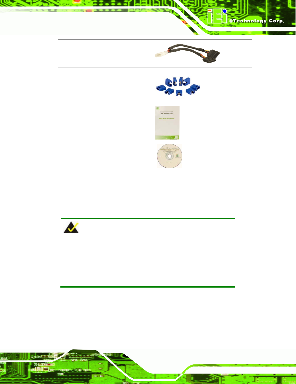
1 SATA power cable
(P/N: 32100-088600-RS)
1 Mini jumper Pack
1 Quick installation guide
1 Utility CD
1 I/O shielding
Table 3-1: Package List Contents
3.3.2 Optional Items
NOTE:
The items listed in this section are optional items that must be ordered
separately. Please contact your KINO-9453 vendor, distributor or
reseller for more information or, cont act IEI directly by sending an email
to
sales@iei.com.tw.
The following optional items are available for the KINO-9453.
Page 27
Page 45

Quantity Item and Part Number Image
1 Dual port USB cable
(P/N: CB-USB02-RS)
1 Four port USB cable
(P/N: CB-USB14-RS)
1 RS-232/422/485 cable
(P/N: 32200-000077-RS)
1 CPU Cooler
(P/N: CF-479B-RS)
KINO-9453 Mini-ITX Motherboard
Table 3-2: Optional Items
Page 28
Page 46

KINO-9453 Mini-ITX Motherboard
Chapter
4
4 Connector Pinouts
Page 29
Page 47

4.1 Peripheral Interface Connectors
Section 4.1.1 shows peripheral interface connector locations. Section 4.1.2 lists all the
KINO-9453 Mini-ITX Motherboard
peripheral interface connectors seen in Section
4.1.3.
4.1.1 KINO-9453 Layout
Figure 4-1 shows the on-board peripheral connectors, rear panel peripheral connectors
and on-board jumpers.
Page 30
Figure 4-1: Connector and Jumper Locations
Page 48

KINO-9453 Mini-ITX Motherboard
4.1.2 Peripheral Interface Connectors
Ta b le 4- 1 shows a list of the peripheral interface connectors on the KINO-9453. Detailed
descriptions of these connectors can be found in Section
Connector Type Label
ATX power supply connector 20-pin ATX connector PWR1
Digital I/O connector 10-pin header DIO1
Fan connector (CPU) 3-pin wafer CPU_FAN1
Fan connector (Northbridge) 3-pin wafer NB_FAN1
Fan connector (System) 3-pin wafer SYS_FAN1
Front panel connector 14-pin header F_PANEL1
IDE Interface connector 40-pin box header IDE1
LVDS connector 30-pin crimp LVDS1
LCD backlight connector 6-pin wafer connector CN1
4.2.
PCI slot 124-pin slot PCI2
Serial ATA (SATA) connector 7-pin SATA connector SATA1
Serial ATA (SATA) connector 7-pin SATA connector SATA2
Serial port connector (COM 3) 14-pin header COM3
Serial port connector (COM 4) 10-pin header COM4
SPDIF connector 5-pin header SPDIF1
USB connector 8-pin header USB4
USB connector 8-pin header USB5
Table 4-1: Peripheral Interface Connectors
Page 31
Page 49

4.1.3 External Interface Panel Connectors
T able 4-2 list s the rear pan el connectors on the KINO-9453. Det ailed descriptio ns of these
KINO-9453 Mini-ITX Motherboard
connectors can be found in Section
Connector Type Label
Audio connector Audio jack AUDIO
Ethernet connector RJ-45 LAN/USB1
Ethernet connector RJ-45 LAN/USB2
Keyboard and mouse connector PS/2 connector KBMS1
RS-232 serial port connector Male DB-9 COM1
RS-232 serial port connector Male DB-9 COM2
USB ports USB port LAN/USB1
USB ports USB port LAN/USB2
VGA port con nector Female DB-15 VIDEO
4.3.
DVI connector DVI connector VIDEO
Table 4-2: Rear Panel Connectors
4.2 Internal Peripheral Connectors
Internal peripheral connectors are found on the motherboard and are only accessible
when the motherboard is outside of the chassis. This section has complete descriptions of
all the internal, peripheral connectors on the KINO-9453.
4.2.1 Fan Connectors
CN Label: CPU_FAN1 , NB_FAN1 and SYS_FAN1
CN Type:
CN Location: See
3-pin header
Figure 4-2
Page 32
Page 50

KINO-9453 Mini-ITX Motherboard
CN Pinouts: See Table 4-3
The cooling fan connectors on the KINO-9453 provide a 12 V, 500 mA current to one CPU
cooling fan, one Northbridge cooling fan and one system cooling fan. There is a “sense”
pin in the fan connector , which transfers the fan’ s sen se signal to the syste m BIOS in order
to recognize the fan speed. Please note that only some specific types of fans offer a
rotation signal.
Figure 4-2: Fan Connector Locations
PIN NO. DESCRIPTION
1 GND
2 +12V
3 Sense
Table 4-3: Fan Connector Pinouts
4.2.2 Front Panel Connector
CN Label: F_PANEL1
CN Type:
CN Location: See
14-pin header (2x7)
Figure 4-3
CN Pinouts: See
Table 4-4
Page 33
Page 51

KINO-9453 Mini-ITX Motherboard
The front panel connector connects to several external switches and indicators to monitor
and control the motherboard. These indicators and switches include:
Power
Power button
Reset button
Speaker
HDD
Figure 4-3: Front Panel Connector Location
PIN NO. DESCRIPTION PIN NO. DESCRIPTION
1 Power LED+ 2 Speaker+
3 NC 4 NC
5 Power LED- 6 NC
7 Power Button# 8 Speaker9 Power Button 10 NC
11 IDE LED+ 12 Reset Button
13 IDE LED- 14 Reset Button#
Table 4-4: Front Panel Connector Pinouts
4.2.3 Digital Input/Output Connector
CN Label: DIO1
Page 34
CN Type:
10-pin header (2x5)
Page 52

KINO-9453 Mini-ITX Motherboard
CN Location: See Figure 4-4
CN Pinouts: See
Table 4-5
The DIO connector is managed through a Super I/O chip. The DIO connector pins are
user programmable. The digital IO port of KINO-9453 is 5 V CMOS level.
Figure 4-4: GPIO Connector Location
PIN NO. DESCRIPTION PIN NO. DESCRIPTION
1 GND 2 +5V
3 INPUT0 4 OUTPUT0
5 INPUT1 6 OUTPUT1
7 INPUT2 8 OUTPUT2
9 INPUT3 10 OUTPUT3
Table 4-5: GPIO Connector Pinouts
4.2.4 IDE Connector
CN Label: IDE1
CN Type:
CN Location: See
CN Pinouts: See
40-pin header (2x20)
Figure 4-5
Table 4-6
Page 35
Page 53

KINO-9453 Mini-ITX Motherboard
One primary 40-pin IDE device connector on the KINO-9453 motherboard supports
connectivity to ATA 100 IDE devices with data transfer rates up to 100 MB/s.
Page 36
Figure 4-5: IDE Device Connector Location
PIN NO. DESCRIPTION PIN NO. DESCRIPTION
1 RESET# 2 GND
3 DATA 7 4 DATA 8
5 DATA 6 6 DATA 9
7 DATA 5 8 DATA 10
9 DATA 4 10 DATA 11
11 DATA 3 12 DATA 12
Page 54

KINO-9453 Mini-ITX Motherboard
PIN NO. DESCRIPTION PIN NO. DESCRIPTION
13 DATA 2 14 DATA 13
15 DATA 1 16 DATA 14
17 DATA 0 18 DATA 15
19 GND 20 (KEY)
21 DRQ 22 GND
23 IOW# 24 GND
25 IOR# 26 GND
27 CHRDY 28 GND
29 DACK 30 GND
31 INTERRUPT 32 N/C
33 SA1 34 P66DET
35 SA0 36 SA2
37 HDC CS0# 38 HDC CS1#
39 HDD ACTIVE# 40 GND
Table 4-6: IDE Connector Pinouts
4.2.5 LCD Backlight Connector
CN Label: CN1
CN Type:
CN Location: See
CN Pinouts: See
The LCD backlight connector is for the LCD inverter connection.
6-pin header (1x6)
Figure 4-6
Table 4-7
Page 37
Page 55

KINO-9453 Mini-ITX Motherboard
Figure 4-6: LCD Backlight Connector Location
PIN NO. DESCRIPTION
1 Back Light Power
2 Back Light Power
3 Back Light enable
4 NC
5 GND
6 GND
Table 4-7: LCD Backlight Connector Pinouts
4.2.6 LVDS LCD connector
CN Label: LVDS1
CN Type:
CN Location: See
CN Pinouts: See
The connector supports one or two channel (18 -bit or 24-bit) LVDS pan el.
30-pin connector (2x15)
Figure 4-7
Table 4-8
Page 38
Page 56

KINO-9453 Mini-ITX Motherboard
Figure 4-7: LVDS LCD Connector Location
PIN NO. DESCRIPTION PIN NO. DESCRIPTION
1 GND 2 GND
3 1st LVDS data0 output + 4 1st LVDS data0 output 5 1st LVDS data1 output + 6 1st LVDS data1 output 7 1st LVDS data2 output + 8 1st LVDS data2 output 9 1st LVDS clock output + 10 1st LVDS clock output 11 NC 12 NC
13 GND 14 GND
15 2nd LVDS data0 output + 16 2nd LVDS data0 output 17 2nd LVDS data1 output + 18 2nd LVDS data1 output 19 2nd LVDS data2 output + 20 2nd LVDS data2 output 21 2
23 NC 24 NC
25 GND 26 GND
27 +LCD (3.3V, 5V or 12V) 28 +LCD (3.3V, 5V or 12V)
29 +LCD (3.3V, 5V or 12V) 30 +LCD (3.3V, 5V or 12V)
nd
LVDS clock output + 22 2nd LVDS clock output -
Table 4-8: LVDS LCD Connector Pinouts
Page 39
Page 57

4.2.7 Power Connector
CN Label: PWR1
KINO-9453 Mini-ITX Motherboard
CN Type:
CN Location: See
CN Pinouts: See
20-pin connector
Figure 4-8
Table 4-9
This 20-pin power connector supports the ATX power supply.
Figure 4-8: Power Connector Location
Page 40
PIN NO. DESCRIPTION PIN NO. DESCRIPTION
1 3.3V 11 3.3V
2 3.3V 12 -12V
3 GND 13 GND
4 +5V 14 PS_ON
5 GND 15 GND
6 +5V 16 GND
7 GND 17 GND
8 Power good 18 -5V
9 5VSB 19 +5V
10 +12V 20 +5V
Table 4-9: Power Connector Pinouts
Page 58

KINO-9453 Mini-ITX Motherboard
4.2.8 14-Pin Serial Port Connectors
CN Label: COM3
CN Type:
CN Location: See
CN Pinouts: See
14-pin header (2x7)
Figure 4-9
Table 4-10
The serial ports connectors connect to RS-232/422/485 serial port device.
Figure 4-9: 14-Pin Serial Port Connector Locations
PIN NO. DESCRIPTION PIN NO. DESCRIPTION
1 DCD 2 DSR
3 RXD 4 RTS
5 TXD 6 CTS
7 DTR 8 RI
9 GND 10 NC
11 TX+ 12 TX-
13 RX+ 14 RX-
Table 4-10: COM2 Pinouts
Page 41
Page 59

4.2.9 10-Pin Serial Port Connectors
CN Label: COM4
KINO-9453 Mini-ITX Motherboard
CN Type:
CN Location: See
CN Pinouts: See
10-pin header (2x5)
Figure 4-10
Table 4-11
The serial ports connectors connect to RS-232 serial port device.
Figure 4-10: 10-Pin Serial Port Connector Locations
PIN NO. DESCRIPTION PIN NO. DESCRIPTION
1 DCD 2 DSR
3 RXD 4 RTS
5 TXD 6 CTS
7 DTR 8 RI
9 GND 10 NC
Table 4-11: COM4 Pinouts
4.2.10 SATA Drive Connectors
CN Label: SATA1 and SATA2
7-pin SATA drive connector (1x7)
Page 42
CN Type:
Page 60

KINO-9453 Mini-ITX Motherboard
CN Location: See Figure 4-11
CN Pinouts: See
Table 4-12
The two SATA drive connectors are connected to four SATA drives. SATA drives transfer
data at speeds as high as 1.5 Gb/s.
Figure 4-11: SATA Drive Connector Locations
PIN NO. DESCRIPTION
1 GND
2 TXP
3 TXN
4 GND
5 RXN
6 RXP
7 GND
Table 4-12: SATA Drive Connector Pinouts
4.2.11 SPDIF Connector
CN Label: SPDIF1
CN Type:
5-pin header (1x5)
Page 43
Page 61

KINO-9453 Mini-ITX Motherboard
CN Location: See Figure 4-12
CN Pinouts: See
Table 4-13
The SPDIF connector connects to the S/PDIF audio module, which bears S/PDIF digital
output. S/PDIF (Sony/Philips Digital Interface) is a newest audio transfer file format, which
allows the user to enjoy digital audio. The SPDIF1 port provides digital audio to external
speaker or compressed AC 3 dat a to an external Dolby Digit al Decod er via a co axial cable.
Figure 4-12: SPDIF Connector Locations
PIN NO. DESCRIPTION
1 +5V
2 (KEY)
3 SPDIF_OUT
4 GND
5 SPDIF_IN
Table 4-13: SPDIF Pinouts
4.2.12 Internal USB Connectors
CN Label: USB4 and USB5
CN Type:
CN Location: See
8-pin header (2x4)
Figure 4-13
Page 44
Page 62
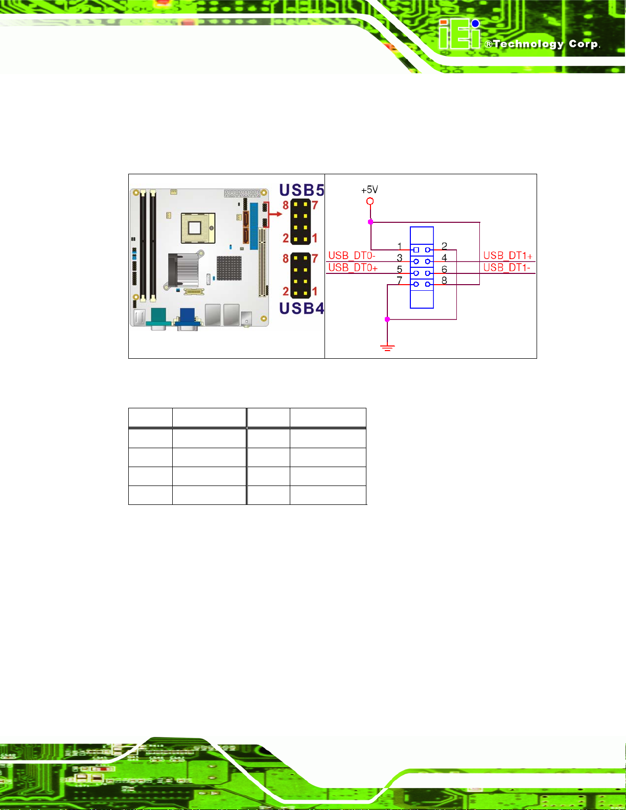
KINO-9453 Mini-ITX Motherboard
CN Pinouts: See Table 4-14
One 2x4 pin connector provides connectivity to two USB 2.0 ports. The USB ports are
used for I/O bus expansion.
Figure 4-13: Internal USB Connector Locations
PIN NO. DESCRIPTION PIN NO. DESCRIPTION
1 VCC 2 GND
3 DATA0- 4 DATA1+
5 DATA0+ 6 DATA17 GND 8 VCC
Table 4-14: USB3 and USB4 Pinouts
4.3 External Interface Connectors
The peripheral connectors on the back panel are connected to devices externally when
the KINO-9453 is installed in a chassis. The peripheral connectors on the rear panel are:
2 x Audio jacks
1 x VGA connector
2 x RJ-45 Ethernet connectors
2 x Keyboard/mouse connectors
2 x Serial port connectors
Page 45
Page 63

1 x DVI connector
4 x USB 2.0 connectors
Figure 4-14: KINO-9453 External Interface Connectors
4.3.1 Audio Connectors
CN Label: AUDIO
KINO-9453 Mini-ITX Motherboard
CN Type:
CN Location: See
CN Pinouts: See
Line Out port (Lime): Connects a headphon e or a speaker. In 4,6,8-channel
configuration, the function of this port becomes Front Speaker Out.
Microphone (Pink): Connects a microphone.
Audio jack
Figure 4-14
Figure 4-15
Figure 4-15: Audio Connectors
Page 46
Page 64

KINO-9453 Mini-ITX Motherboard
4.3.2 CRT Connector
CN Label: VIDEO
CN Type:
CN Location: See
CN Pinouts: See
15-pin female connector
Figure 4-14
Table 4-15
The standard 15-pin VGA connector connects to a CRT or LCD display monitor.
Figure 4-16: VGA Connector
PIN NO. DESCRIPTION PIN NO. DESCRIPTION
1 RED 2 GREEN
3 BLUE 4 N/C
5 GND 6 GND
7 GND 8 GND
9 VCC 10 GND
11 N/C 12 DDC DAT
13 HSYNC 14 VSYNC
15 DDC CLK
Table 4-15: VGA Connector Pinouts
4.3.3 DVI Connector
CN Label: VIDEO
CN Type:
DVI interface with analog RGB signal
Page 47
Page 65

KINO-9453 Mini-ITX Motherboard
CN Location: See Figure 4-14
CN Pinouts: See
Figure 4-17 and Table 4-16
The KINO-9453 has an external DVI connector.
Figure 4-17 DVI-I Connector Pinout Locations
PIN Description PIN Description PIN Description
1 DTX2- 9 DTX1- 17 DTX0-
2 DTX2+ 10 DTX1+ 18 DTX0+
3 GND 11 GND 19 GND
4 N/C 12 N/C 20 N/C
5 N/C 13 N/C 21 N/C
6 SB_CK_C 14 PVDD1 22 GND
6 SB_DA_C 15 GND 23 DTXC+
8 V_SYNC 16 GND 24 DTXC-
C1 R C3 B 25 GND
C5 GND C6 GND 26 GND
C2 G C4 H_SYNC
Table 4-16: DVI-I Connector Pinouts
4.3.4 Ethernet Connectors
CN Label: LAN/USB1 and LAN/USB2
CN Type:
CN Location: See
CN Pinouts: See
RJ-45
Figure 4-14
Table 4-17
Page 48
Page 66

KINO-9453 Mini-ITX Motherboard
The KINO-9453 is equipped with two built-in GbE Ethernet controllers. The controllers can
connect to the LAN through two RJ-45 LAN connectors. There are two LEDs on the
connector indicating the status of LAN. The pin assignments are listed in the following
table:
PIN DESCRIPTION PIN DESCRIPTION
1 MDX0+ 5 MDX2-
2 MDX0- 6 MDX13 MDX1+ 7 MDX3+
4 MDX2+ 8 MDX3-
Table 4-17: LAN1 and LAN2 Pinouts
Figure 4-18: RJ-45 Ethernet Connector
The RJ-45 Ethernet connector has two status LE Ds, one g reen and one yellow. The green
LED indicates activity on the port and the yellow LED indicates the port is linked. See
Table 4-18.
SPEED LED ACT/LINK LED
STATUS DESCRIPTION STATUS DESCRIPTION
OFF 10Mbps connection OFF No link
ORANGE 100Mbps connection YELLOW Linked
GREEN 1Gbps connection BLINKING Data Activity
Table 4-18: RJ-45 Ethernet Connector LEDs
Page 49
Page 67

4.3.5 Keyboard/Mouse Connector
CN Label: KBMS1
KINO-9453 Mini-ITX Motherboard
CN Type:
CN Location: See
CN Pinouts: See
PS/2 connector
Figure 4-14
Table 4-19 and Figure 4-19
The KINO-9453 keyboard and mouse connectors are standard PS/2 connectors.
Figure 4-19: PS/2 Pinouts
Page 50
PIN DESCRIPTION PIN DESCRIPTION
1 L_KDAT 7 L_MDAT
2 NC 8 NC
3 GND 9 GND
4 5V 10 5V
5 L_KCLK 11 L_MCLK
6 NC 12 NC
Table 4-19: PS/2 Connector Pinouts
Page 68

KINO-9453 Mini-ITX Motherboard
4.3.6 Serial Port Connectors
CN Label: COM1/2
CN Type:
CN Location: See
CN Pinouts: See
DB-9
Figure 4-14
Table 4-20 and Figure 4-20
The serial ports can be connected to a serial communications device directly.
Figure 4-20: External Serial Port Connector
PIN Description
1 DATA CARRIER DETECT (DCD)
2 RECEIVE DATA (RXD)
3 TRANSMIT DATA (TXD)
4 DATA TERMINAL READY (DTR)
5 GROUND (GND)
6 DATA SET READY (DSR)
7 REQUEST TO SEND (RTS)
8 CLEAR TO SEND (CTS)
9 RING INDICATOR (RI)
Table 4-20: External Serial Port Pinouts
Page 51
Page 69

4.3.7 USB Connector
CN Label: LAN/USB1 and LAN/USB2
KINO-9453 Mini-ITX Motherboard
CN Type:
CN Location: See
CN Pinouts: See
USB devices can be connected directly to the USB connectors on the rear panel.
PIN NO. DESCRIPTION PIN NO. DESCRIPTION
1 VCC 5 VCC
2 USBD0- 6 USBD13 USBD0+ 7 USBD1+
4 GND 8 GND
Table 4-21: External USB Connector Pinouts
USB port
Figure 4-14
Table 4-21
Page 52
Page 70

KINO-9453 Mini-ITX Motherboard
Chapter
5
5 Installation
Page 53
Page 71

5.1 Anti-static Precautions
WARNING:
Failure to take ESD precautions during the installation of the
KINO-9453 may result in permanent damage to the KINO-9453 and
severe injury to the user.
Electrostatic discharge (ESD) can cause serious damage to electronic components,
including the KINO-9453. Dry climates are especially susceptible to ESD. It is therefore
critical that whenever the KINO-9453, or any other electrical component is handled, the
following anti-static precautions are strictly adhered to.
KINO-9453 Mini-ITX Motherboard
Wear an anti-static wristband: Wearing a simple ant i-static wristband can
help to prevent ESD from damaging the board.
Self-grounding: Before handling the board touch any grounded conducting
material. During the time the board is handled, frequently touch any
conducting materials that are connected to the ground.
Use an anti-static pad: When configuring the KINO-9453, place it on an
antic-static pad. This reduces the possibility of ESD damaging the
KINO-9453.
Only handle the edges of the PCB: When handling the PCB, hold the PCB
by the edges.
Page 54
Page 72

KINO-9453 Mini-ITX Motherboard
5.2 Installation Considerations
NOTE:
The following installation notices and installation considerations should
be read and understood before the KINO-9453 is installed. All
installation notices pertaining to the installation of the KINO-9453
should be strictly adhered to. Failing to adhere to these precautions
may lead to severe damage of the KINO-9453 and injury to the person
installing the motherboard.
5.2.1 Installation Notices
WARNING:
The installation instructions described in this manual should be
carefully followed in order to prevent damage to the KINO-9453,
KINO-9453 components and injury to the user.
Before and during the installation please DO the following:
Read the user manual:
o The user manual provides a complete description of the KINO-9453
installation instructions and configuration options.
Wear an electrostatic discharge cuff (ESD):
o Electronic components are easily damaged by ESD. Wearing an ESD cuff
removes ESD from the body and helps prevent ESD damage.
Place the KINO-9453 on an antistatic pad:
o When installing or configuring the motherboard, place it on an antistatic
pad. This helps to prevent potential ESD damage.
Turn all power to the KINO-9453 off:
Page 55
Page 73

o When working with the KINO-9453, make sure that it is di sconnected from
all power supplies and that no electricity is being fed into the system.
Before and during the installation of the KINO-9453 DO NOT:
Remove any of the stickers on the PCB board. These stickers are required for
warranty validation.
Use the product before verifying all the cables and power connectors are
properly connected.
Allow screws to come in contact with the PCB circuit, connector pins, or its
components.
5.2.2 Installation Checklist
The following checklist is provided to ensure the KINO-9453 is properly installed .
KINO-9453 Mini-ITX Motherboard
All the items in the packing list are present
The CPU is installed
The CPU cooling kit is properly installed
A compatible memory module is properly inserted into the slot
The CF Type I or CF Type II card is pro perly installed into the CF socket
The jumpers have been properly configured
The KINO-9453 is inserted into a chassis with adequate ventilation
The correct power supply is being used
The following devices are properly connected
o IDE device
o SATA drives
o Keyboard and mouse cable
o Audio kit
o Power supply
o USB cable
o Serial port cable
o Parallel port cable
Page 56
The following external peripheral devices are properly connected to the
chassis:
o VGA screen
Page 74

KINO-9453 Mini-ITX Motherboard
o Keyboard
o Mouse
o RS-232 serial communications device
5.3 CPU, CPU Cooling Kit and DIMM Installation
WARNING:
A CPU should never be turned on without the specified cooling kit
being installed. If the cooling kit (heat sink and fan) is not properly
installed and the system turned on, permanent damage to the CPU,
KINO-9453 and other electronic components attached to the system
may be incurred. Running a CPU without a cooling kit may also result
in injury to the user.
The CPU, CPU cooling kit and DIMM are the most critical components of the KINO-9453.
If one of these component is not installed the KINO-9453 cannot run.
5.3.1 Socket 479 CPU Installation
WARNING:
CPUs are expensive and sensitive components. When installing the
CPU please be careful not to damage it in anyway. Make sure the CPU
is installed properly and ensure the correct cooling kit is properly
installed.
To install a socket 479 CPU onto the KINO-9453, follow the steps below:
Page 57
Page 75

KINO-9453 Mini-ITX Motherboard
WARNING:
When handling the CPU, only hold it on the sides. DO NOT touch the
pins at the bottom of the CPU.
Step 1: Unlock the CPU retention screw. When shipped, the retention screw of the
CPU socket should be in the unlocked position. If it is not in the unlocked
position, use a screwdriver to unlock the screw. See
Figure 5-1.
Figure 5-1: Make sure the CPU socket retention screw is unlocked
Page 58
Step 2: Inspect the CPU socket. Make sure there are no bent pins and make sure the
socket contacts are free of foreign material. If any debris is found, remove it with
compressed air.
Step 3: Correctly Orientate the CPU. Make sure the IHS (integrated heat sink) side is
facing upwards.
Step 4: Correctly position the CPU. Match the Pin 1 mark with the cut edge on the
CPU socket. See
Figure 5-1.
Page 76

KINO-9453 Mini-ITX Motherboard
Step 5: Align the CPU pins. Carefully align the CPU pins with the holes in the CPU
socket.
Step 6: Insert the CPU. Gently insert the CPU into the socket. If the CPU pins are
properly aligned, the CPU should slide into the CPU socket smoothly.
Step 7: Lock the retention screw. Rotate the retention screw into the locked position.
Figure 5-2.
See
Figure 5-2: Lock the CPU Socket Retention Screw
Page 59
Page 77

5.3.2 Cooling Kit CF-479B-RS Installation
Figure 5-3: IEI CF-479B-RS Cooling Kit
An IEI Socket 479 CPU cooling kit can be purchased separately. The cooling kit comprises
a CPU heat sink and a cooling fan.
KINO-9453 Mini-ITX Motherboard
WARNING:
Do not wipe off (accidentally or otherwise) the pre-sprayed layer of
thermal paste on the bottom of the CF-479B-RS heat sink. The thermal
paste between the CPU and the heat sink is important for optimum
heat dissipation.
To install the CF-479B-RS cooling kit, please follow the steps below.
Step 1: Place the cooling kit onto the CPU. Make sure the CPU cooling fan cable
can be properly routed when the cooling kit is install ed.
Step 2: Properly align the cooling kit. Make sure its four spring screw fasteners can
pass through the pre-drilled holes on the PCB.
Step 3: Secure the cooling kit. From the solder side of the PCB, align the support
Page 60
bracket to the screw threads on heat sink that were inserted through the PCB
holes. (See
Figure 5-4)
Page 78

KINO-9453 Mini-ITX Motherboard
Figure 5-4: Cooling Kit Support Bracket
Step 4: Tighten the screws. Use a screwdriver to tighten the four screws. Tighten each
nut a few turns at a time and do not over-tighten the screws.
Step 5: Connect the fan cable. Connect the cooling kit fan cable to the fan connector
on the motherboard. Carefully route the cable and avoid heat generating chips
and fan blades. See
Figure 5-5: Connect the cooling fan cable
Figure 5-5.
Page 61
Page 79

5.3.3 DIMM Installation
WARNING:
Only DDR2 memory module can be installed on the KINO-9453. Do not
install DDR memory modules. If a DDR memory module is installed on
the KINO-9453, the KINO-9453 may be irreparably damaged. Please
make sure the purchased DIMM complies with the memory
specifications of the KINO-9453. DIMM specifications compliant with
the KINO-9453 are listed in Chapter 2.
KINO-9453 Mini-ITX Motherboard
To install a DIMM into a DIMM socket, please follow the steps below and refer to
Figure 5-6.
Figure 5-6: Installing a DIMM
Page 62
Step 1: Open the DIMM socket handles. The DIMM socket has two handles that
secure the DIMM into the socket. Before the DIMM can be inserted into the
socket, the handles must be opened. See
Figure 5-6.
Page 80

KINO-9453 Mini-ITX Motherboard
Step 2: Align the DIMM with the socket. The DIMM must be oriented in such a way
that the notch in the middle of the DIMM must be aligned with the plastic bridge
in the socket. See
Step 3: Insert the DIMM. Once properly aligned, the DIMM can be inserted into the
socket. As the DIMM is inserted, the white handles on the side of the socket will
close automatically and secure the DIMM to the socket. See
Step 4: Removing a DIMM. To remove a DIMM, push both handles outward. The
memory module is ejected by a mechanism in the socket.Step 0:
5.4 Jumper Settings
NOTE:
A jumper is a metal bridge used to close an
electrical circuit. It consists of two or three metal
pins and a small metal clip (often protected by a
plastic cover) that slides over the pins to connect
Figure 5-6.
Figure 5-6.
them. To CLOSE/SHORT a jumper means
connecting the pins of the jumper with the plastic
clip and to OPEN a jumper means removing the
plastic clip from a jumper.
Before the KINO-9453 is installed in the system, the jumpers must be set in accordance
with the desired configuration. The jumpers on the KINO-9453 are listed in
Description Label Type
AT/ATX power mode selection JP5, JP6 2-pin header
Clear CMOS JP3 3-pin header
COM3 mode selection JP1, JP7 6-pin header
LVDS LCD voltage selection JP4 4-pin header
Figure 5-7: Jumper Locations
Table 5-1.
Page 63
Page 81
L VDS screen resolution sel ection JP2 8-pin h eader
RS-422 termination resister JP8 2-pin header
RS-485 termination resister JP9 2-pin header
Table 5-1: Jumpers
5.4.1 AT/ATX Power Select Jumper Settings
Jumper Label: JP5 and JP6
KINO-9453 Mini-ITX Motherboard
Jumper Type:
Jumper Settings: See
Jumper Location:
2-pin header
Table 5-2
Figure 5-8
See
The AT/ATX Power Select jumper specifies the systems power mode as AT or ATX.
AT/ATX Power Select jumper settings are shown in
JP5 Description
Short Use ATX power Default
Open Use AT power
JP6 Description
Short Use AT power
Open Use ATX power Default
Table 5-2.
Table 5-2: AT/ATX Power Select Jumper Settings
Page 64
The location of the AT/ATX Power Select jumper is shown in Figure 5-8 below.
Page 82

KINO-9453 Mini-ITX Motherboard
Figure 5-8: AT/ATX Power Select Jumper Location
5.4.2 Clear CMOS Jumper
Jumper Label: JP3
Jumper Type:
Jumper Settings: See
Jumper Location: See
If the KINO-9453 fails to boot due to improper BIOS settings, the clear CMOS jumper
clears the CMOS data and resets the system BI OS informatio n. To do this, use the jumper
cap to close pins 2 and 3 for a few seconds then reinstall the jumper clip back to pins 1
and 2.
If the “CMOS Settings Wrong” message is displayed during the boot up process, the fault
3-pin header
Table 5-3
Figure 5-9
may be corrected by pressing the F1 to enter the CMOS Setup menu. Do one of the
following:
Enter the correct CMOS setting
Page 65
Page 83

Load Optimal Defaults
Load Failsafe Defaults.
KINO-9453 Mini-ITX Motherboard
After having done one of the above, save the changes and exit the CMOS Setup menu.
The clear CMOS jumper settings are shown in
Clear CMOS Description
Short 1 - 2 Keep CMOS Setup Default
Short 2 - 3 Clear CMOS Setup
Table 5-3.
Table 5-3: Clear CMOS Jumper Settings
The location of the clear CMOS jumper is shown in Figure 5-9 below.
Page 66
Figure 5-9: Clear CMOS Jumper
Page 84

KINO-9453 Mini-ITX Motherboard
5.4.3 COM 3 Function Select Jumper
Jumper Label: JP1 and JP7
Jumper Type:
Jumper Settings: See
Jumper Location: See
6-pin header
Table 5-4
Figure 5-10
The COM 3 Function Select jumper sets the communication protocol used by the second
serial communications port (COM 3) as RS-232, RS-422 or RS -485. The COM 3 Function
Select settings are shown in
JP1 Description
Short 1-2 RS-232 Default
Short 3-4 RS-422
Short 5-6 RS-485
JP7 Description
Short 1-3, 2-4 RS-232 Default
Short 3-5, 4-6 RS-485
Table 5-4.
Table 5-4: COM 3 Function Select Jumper Settings
The COM 3 Function Select jumper location is shown in Figure 5-10.
Page 67
Page 85

KINO-9453 Mini-ITX Motherboard
Figure 5-10: COM 3 Function Select Jumper Locations
5.4.4 RS-422 or RS-486 Termination Resister
Jumper Label: JP8 and JP9
Jumper Type:
Jumper Settings:
Jumper Location:
The JP8 sets the RS-422 Termination Resister while JP9 sets the RS-485 Termination
Resister. The RS-422 and RS-485 Termination Resister settings are shown in
and
Table 5-6.
JP8 Description
Open Normal Operation Default
Short Termination Resister Setting
Table 5-5: RS-422 Termination Resister Jumper Settings
2-pin header
Table 5-5 and Table 5-6
See
Figure 5-11
See
Table 5-5
Page 68
Page 86

KINO-9453 Mini-ITX Motherboard
JP9 Description
Open Normal Operation Default
Short Termination Resister Setting
Table 5-6: RS-485 Termination Resister Jumper Settings
The RS-422 or RS-485 Termination Resister jumper location is shown in Figure 5-11.
Figure 5-11: RS-422 and RS-485 Termination Resister Jumper Locations
5.4.5 LVDS Screen Resolution Selection
Jumper Label: JP2
Jumper Type:
Jumper Settings: See
Jumper Location: See
The LVDS Screen Resolution Selection jumper allows the LVDS screen resolution to be
set. The LVDS Screen Resolution Selection jumper settings are shown in
8-pin header
Table 5-8
Figure 5-13
Table 5-8.
Page 69
Page 87

LVDS Resolution Select Description
Open By BIOS setting
Short 3-4 800 x 600 (18-bit) Default
Short 5-6 1024 x 768 (24-bit)
Short 1-2, 3-4 1024 x 768 (18-bit)
Short 1-2, 3-4, 5-6 1600 x 1200 (48-bit)
Short 3-4, 5-6 1280 x 1024 (48-bit)
Short 7-8 1280 x 768 (18-bit)
Short 1-2, 7-8 1280 x 800 (18-bit)
Short 3-4, 7-8 1366 x 768 (18-bit)
Short 1-2, 3-4, 7-8 1440 x 900 (36-bit)
Short 5-6, 7-8 1440 x 900 (48-bit)
Short 1-2, 5-6, 7-8 1680 x 1050 (48-bit)
KINO-9453 Mini-ITX Motherboard
Table 5-7: LVDS Screen Resolution Selection Jumper Settings
The LVDS Screen Resolution Selection jumper location is shown in Figure 5-13.
Page 70
Page 88

KINO-9453 Mini-ITX Motherboard
Figure 5-12: LVDS Screen Resolution Selection Jumper Pinout Locations
5.4.6 LVDS Voltage Selection
WARNING:
Permanent damage to the screen and KINO-9453 may occur if the
wrong voltage is selected with this jumper. Please refer to the user
guide that cam with the monitor to select the correct voltage.
Jumper Label: JP4
Jumper Type:
Jumper Settings: See
4-pin header
Table 5-8
Jumper Location: See
Figure 5-13
Page 71
Page 89

KINO-9453 Mini-ITX Motherboard
The LVDS V olt age Selection jumper allows the LVDS screen voltage to be set. The LVDS
Voltage Selection jumper settings are shown in
LVDS Voltage Select Description
Short 1-2 +3V Default
Short 3-4 +5V
Table 5-8.
Table 5-8: LVDS Voltage Selection Jumper Settings
The LVDS Voltage Selection jumper location. is shown in Figure 5-13.
Figure 5-13: LVDS Voltage Selection Jumper Pinout Locations
Page 72
Page 90

KINO-9453 Mini-ITX Motherboard
5.5 Chassis Installation
5.5.1 Airflow
WARNING:
Airflow is critical to the cooling of the CPU and other onboard
components. The chassis in which the KINO-9453 must have air vents
to allow cool air to move into the system and hot air to move out.
The KINO-9453 must be installed in a chassis with ventilation holes on the sides allowing
airflow to travel through the heat sink surface. In a system with an individual power supply
unit, the cooling fan of a power supply can also help generate airflow through the board
surface.
NOTE:
IEI has a wide range of backplanes available. Please contact your
KINO-9453 vendor, reseller or an IEI sales representative at
sales@iei.com.tw or visit the IEI website (http://www.ieiworld.com.tw)
to find out more about the available chassis.
5.5.2 Motherboard Installation
To install the KINO-9453 motherboard into the chassis please refer to the reference
material that came with the chassis.
Page 73
Page 91

KINO-9453 Mini-ITX Motherboard
5.6 Internal Peripheral Device Connections
5.6.1 Peripheral Device Cables
The cables listed in Table 5-9 are shipped with the KINO-9453.
Quantity Type
1 IDE Cable
1 Dual RS-232 cable
2 SAT A drive cables
1 SATA drive power cable
Table 5-9: IEI Provided Cables
Optional cables are listed below:
USB cable (dual port)
USB cable (four port)
RS-232/422/485 cable
5.6.2 IDE Cable Connection
The IDE flat cable connects to the KINO-9453 to one or two IDE devices. To connect an
IDE HDD to the KINO-9453, please follow the instructions below.
Step 1: Locate the IDE connector. The location/s of the IDE device connector/s is/are
shown in Chapter 3.
Step 2: Insert the connector. Connect the IDE cable connector to the onboard
connector. See
can only be inserted in one direction.
Figure 5-14. A key on the front of the cable connector ensures it
Page 74
Page 92

KINO-9453 Mini-ITX Motherboard
Figure 5-14: IDE Cable Connection
Step 3: Connect the cable to an IDE device. Connect the two connectors on the other
side of the cable to one or two IDE devices. Make sure that pin 1 on the cable
corresponds to pin 1 on the connectorStep 0:
5.6.3 Dual RS-232 Cable Connection
The dual RS-232 cable consists of two connectors attached to two independent cables.
Each cable is then attached to a D-sub 9 male connector that is mounted onto a bracket.
To install the dual RS-232 cable, please follow the steps below.
Step 1: Locate the connectors. The locations of the RS-232 connectors are shown in
Chapter 3.
Step 2: Insert the cable connectors. Insert one connector into each serial port box
headers. See
the connector can only be installed in one direction.
Figure 5-15. A key on the front of the cable connectors ensures
Page 75
Page 93

KINO-9453 Mini-ITX Motherboard
Figure 5-15: Dual RS-232 Cable Installation
Step 3: Secure the bracket. The dual RS-232 connector has two D-sub 9 male
connectors secured on a bracket. To secure the bracket to the chassis please
refer to the reference material that came with the chassisStep 0:
5.6.4 SATA Drive Connection
The KINO-9453 is shipped with two SATA drive cables and one SATA drive power cable.
To connect the SATA drives to the connectors, please follow the steps below.
Step 1: Locate the connectors. The locations of the SATA drive connectors are shown
in Chapter 3.
Step 2: Insert the cable connector. Press the clip on the connector at the end of the
SATA cable and insert the cable connector into the onboard SATA drive
Page 76
connector. See
Figure 5-16.
Page 94

KINO-9453 Mini-ITX Motherboard
Figure 5-16: SATA Drive Cable Connection
Step 3: Connect the cable to the SATA disk. Connect the connector on the other end
of the cable to the connector at the back of the SATA drive. See
Figure 5-17.
Step 4: Connect the SATA power cable. Connect the SATA power connector to the
back of the SATA drive. See
Figure 5-17.
Figure 5-17: SATA Power Drive Connection
Page 77
Page 95

KINO-9453 Mini-ITX Motherboard
5.7 External Peripheral Interface Connection
The following external peripheral devices can be connected to the external peripheral
interface connectors.
Audio devices
RJ-45 Ethernet cable
USB devices
VGA monitors
DVI port devices
Serial port devices
Mouse and keyboard
To install these devices, connect the corresponding cable connector from the actual
device to the corresponding KINO-9453 external peripheral interface connector making
sure the pins are properly aligned.
5.7.1 Audio Connection
Audio signals are interfaced through two phone jack connections. The red phone jack is
for Line Out and green is for MIC In. Follow the steps below to connect audio devices to
the KINO-9453.
Step 1: Locate the audio phone jacks. The location of the audio phone jacks are
shown in Chapter 3.
Step 2: Insert audio phone jack plugs. Insert audio phone jack plugs into the audio
phone jacks on the external peripheral interface. See
Figure 5-18.
Page 78
Page 96

KINO-9453 Mini-ITX Motherboard
Figure 5-18: Audio Connectors
5.7.2 RJ-45 Ethernet Connection
The KINO-9453 has two RJ-45 Ethernet connectors on the external peripheral interface
panel for LAN communications. Follow the steps below to connect an RJ-45 Ethernet
connector to the KINO-9453.
Step 1: Locate the RJ-45 connector. The location of the RJ-45 connector is shown in
Chapter 3.
Step 2: Insert an RJ-45 plug. Insert the RJ-45 plug of a LAN into the RJ-45 receptacle
on the external peripheral interface. See
Figure 5-19.
Page 79
Page 97

KINO-9453 Mini-ITX Motherboard
Figure 5-19: RJ-45 Ethernet Connector
5.7.3 USB Connection
The external USB Series "A" receptacle connectors provide easier and quicker access to
external USB devices. Follow the steps below to connect USB devices to the KINO-9453.
Step 1: Locate the USB Series "A" receptacle connectors. The location of the USB
Series "A" receptacle connectors are shown in Chapter 3.
Step 2: Insert a USB Series "A" plug. Insert the USB Series "A" plug of a device into
the USB Series "A" receptacle on the external peripheral interface. See
5-20.
Figure
Page 80
Page 98

KINO-9453 Mini-ITX Motherboard
Figure 5-20: USB Connector
5.7.4 VGA Monitor Connection
The KINO-9453 has a single female DB-15 connector on the external peripheral interface
panel. The DB-15 connector is connected to a CRT or VGA monitor. To connect a monitor
to the KINO-9453, please follow the instructions below.
Step 1: Locate the female DB-15 connector. The location of the female DB-15
connector is shown in Chapter 3.
Step 2: Align the VGA connector. Align the male DB-15 connector on the VGA screen
cable with the female DB-15 connector on the external peripheral interface.
Step 3: Insert the VGA connector. Once the connectors are properly aligned with the
insert the male connector from the VGA screen into the female connector on the
KINO-9453. See
Figure 5-21.
Page 81
Page 99

KINO-9453 Mini-ITX Motherboard
Figure 5-21: VGA Connector
Step 4: Secure the connector. Secure the DB-15 VGA connector from the VGA
monitor to the external interface by tightening the two retention screws on either
side of the connector. Step 0:
5.7.5 Serial Device Connection
The KINO-9453 has two female DB-9 connectors on the external peripheral interface
panel for serial devices. Follow the steps below to connect a serial device to the
KINO-9453.
Step 1: Locate the DB-9 connector. The location of the DB-9 connector is shown in
Chapter 3.
Step 2: Insert the serial connector. Insert the DB-9 connector of a serial device into
the DB-9 connector on the external peripheral interface. See
Figure 5-22.
Page 82
Page 100
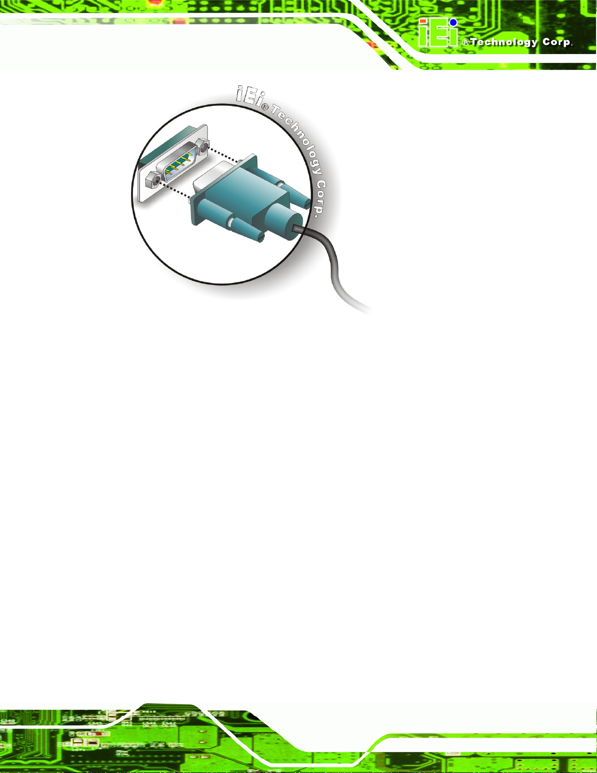
KINO-9453 Mini-ITX Motherboard
Figure 5-22: Serial Device Connector
Step 3: Secure the connector. Secure the serial device connector to the external
interface by tightening the two retention screws on either side of the connector.
5.7.6 PS/2 Keyboard/Mouse Connection
The KINO-9453 has a dual PS/2 connector on the external peripheral interfa ce panel. The
dual PS/2 connector is used to connect to a keyboard and mouse to the system. Follow
the steps below to connect a keyboard and mouse to the KINO-9453.
Step 1: Locate the dual PS/2 connector. The location of the dual PS/2 connector is
shown in Chapter 3.
Step 2: Insert the keyboard/mouse connector. Insert a PS/2 keyboard or mouse
connector into the appropriate PS/2 connector on the external peripheral
Step 0:
interface connector . See
Figure 5-23. Step 0:
Page 83
 Loading...