

Page 1

MODEL:
Video Wall Controller
iVW-UD322iVW-UD322 Video Wall Controller
iVW-UD322 / iVW-UD322F
Supports 2 x 2, 2 x 1, 3x1, 1x3, 4x1 & 1x4 Video Wall Array
User Manual
Rev. 1.01
i
Page 2

iVW-UD322iVW-UD322 Video Wall Controller
COPYRIGHT NOTICE
The information in this document is subject to change without prior notice in order to
improve reliability, design and function and does not represent a commitment on the part
of the manufacturer.
In no event will the manufacturer be liable for direct, indirect, special, incidental, or
consequential damages arising out of the use or inability to use the product or
documentation, even if advised of the possibility of such damages.
This document contains proprietary information protected by copyright. All rights are
Copyright
reserved. No part of this manual may be reproduced by any mechanical, electronic, or
other means in any form without prior written permission of the manufacturer.
TRADEMARKS
All registered trademarks and product names mentioned herein are used for identification
purposes only and may be trademarks and/or registered trademarks of their respective
owners.
ii
Page 3

iVW-UD322iVW-UD322 Video Wall Controller
Table of Contents
COPYRIGHT ................................................................................................................... II
TABLE OF CONTENTS ................................................................................................ III
LIST OF FIGURES .......................................................................................................... V
LIST OF TABLES ......................................................................................................... VII
1 INTRODUCTION .......................................................................................................... 1
1.1 I
NTRODUCTION
1.2 B
ENEFITS
1.3 F
EATURES
1.4 E
XTERNAL INTERFACES, SWITCHES AND
........................................................................................................... 2
................................................................................................................... 2
................................................................................................................... 2
LEDS .......................................................... 3
1.4.1 Front Panel ........................................................................................................ 3
1.4.2 Rear Panel ......................................................................................................... 3
1.5 T
ECHNICAL SPECIFICATIONS
1.6 D
IMENSIONS
2 PACKING LIST ............................................................................................................. 6
2.1 A
NTI-STATIC PRECAUTIONS
2.2 P
ACKING LIST
3 INSTALLATION ........................................................................................................... 9
3.1 R
EQUIREMENTS
3.1.1 Video Card ....................................................................................................... 10
3.1.2 Monitors ........................................................................................................... 10
3.1.3 Cables .............................................................................................................. 10
3.2 P
ANEL SETUP OPTIONS
3.2.1 2 x 2 ................................................................................................................... 11
3.2.2 2 x 1 .................................................................................................................. 12
3.2.3 3 x 1 .................................................................................................................. 12
............................................................................................................... 5
............................................................................................................. 7
........................................................................................................ 10
...................................................................................... 4
........................................................................................ 7
.............................................................................................. 11
3.2.4 4 x 1 .................................................................................................................. 12
3.2.5 1 x 3 .................................................................................................................. 13
3.2.6 1 x 4 .................................................................................................................. 13
iii
Page 4

iVW-UD322iVW-UD322 Video Wall Controller
3.3 I
NSTALL
3.4 M
OUNT THE VIDEO WALL CONTROLLER
3.5 C
ONNECT CABLES
LCD P
ANELS
.............................................................................................. 13
.................................................................... 14
.................................................................................................... 15
3.5.1 Connect the DVI Cables ................................................................................... 15
3.5.2 Connect the iVW-UD322 to the Power Supply ................................................ 15
3.6 R
ESOLUTION AND DISPLAY MODE CHARTS
3.7 S
ETTING VIDEO WALL CONTROLLER AND GRAPHICS CARD RESOLUTION
.............................................................. 16
................ 18
3.7.1 Setting Adjustment Troubleshooting (Manual Adjustment) ............................. 18
3.8 B
EZEL COMPENSATION
............................................................................................. 20
4 OSD FUNCTIONS ....................................................................................................... 21
4.1 ON S
CREEN DISPLAY
(OSD) .................................................................................... 22
4.1.1 OSD Buttons ..................................................................................................... 22
4.1.2 OSD Menu ........................................................................................................ 22
4.1.3 Remote Control ................................................................................................ 32
4.1.4 Reset to Factory Default Settings .................................................................... 32
4.2 S
MART
OSD .............................................................................................................. 33
4.2.1 Installing SmartOSD ........................................................................................ 33
4.2.2 Using SmartOSD .............................................................................................. 39
5 TROUBLESHOOTING AND MAINTENANCE ..................................................... 47
5.1 M
AINTENANCE OVERVIEW
5.2 T
ROUBLESHOOTING
.................................................................................................. 47
....................................................................................... 47
5.2.1 No Image on One Monitor ............................................................................... 47
5.2.2 No Image on Two or More Monitors................................................................ 48
5.2.3 No Image on Any Monitor ................................................................................ 48
iv
Page 5

iVW-UD322iVW-UD322 Video Wall Controller
List of Figures
Figure 1-1: iVW-UD322 overview .............................................................................................. 2
Figure 1-2: iVW-UD322 Front Panel .......................................................................................... 3
Figure 1-3: iVW-UD322 Rear Panel ........................................................................................... 4
Figure 1-4: iVW-UD322 Dimensions ......................................................................................... 5
Figure 3-1: Mounting Brackets ............................................................................................... 14
Figure 3-2: iVW-UD322 Video Input ........................................................................................ 15
Figure 3-4: Display Modes ...................................................................................................... 16
Figure 3–5: Video Card Output Resolution ............................................................................ 19
Figure 3–6: Don't Hide Display Modes not supported by the monitor .................................. 20
Figure 4-1: OSD Buttons ......................................................................................................... 22
Figure 4-2: Mask Control ......................................................................................................... 24
Figure 4-3: Link Control .......................................................................................................... 25
Figure 4-4: Slave Mask Setting ............................................................................................... 26
Figure 4-5: Settings ................................................................................................................. 27
Figure 4-6: Warning ................................................................................................................. 28
Figure 4-7: Information ........................................................................................................... 28
Figure 4-9: Sync and Power .................................................................................................... 29
Figure 4-10: Firmware Information ......................................................................................... 30
Figure 4-11: Serial Number ..................................................................................................... 31
Figure 4-12: Remote Control ................................................................................................... 32
Figure 4-13: Reset to Factory Defaults ................................................................................... 32
Figure 4-14: SmartOSD installation program ......................................................................... 33
Figure 4-15: SmartOSD Welcome Screen ............................................................................... 34
Figure 4-16: SmartOSD Installation Directory ........................................................................ 35
Figure 4-17: SmartOSD Ready to Install ................................................................................. 35
Figure 4-18: SmartOSD Additional Tasks............................................................................... 36
Figure 4-19: SmartOSD Ready to Install ................................................................................. 37
Figure 4-20: SmartOSD Installing ........................................................................................... 37
Figure 4-21: SmartOSD Installation Complete ....................................................................... 38
Figure 4-22: smartOSD PC Setting ......................................................................................... 40
v
Page 6

iVW-UD322iVW-UD322 Video Wall Controller
Figure 4-23: SmartOSD Master Control Panel ........................................................................ 41
Figure 4-24: SmartOSD Slave Control Panel .......................................................................... 43
Figure 4-25: SmartOSD Master Data ....................................................................................... 45
Figure 4-26: SmartOSD About Page ....................................................................................... 46
vi
Page 7

iVW-UD322iVW-UD322 Video Wall Controller
List of Tables
Table 1-1: Technical Specifications .......................................................................................... 5
Table 2-1: Package List Contents ............................................................................................. 8
Table 4-1: OSD Menu Structure .............................................................................................. 23
Table 4-2: SmartOSD Menu Structure .................................................................................... 39
vii
Page 8

iVW-UD322iVW-UD322 Video Wall Controller
1 Introduction
Chapter
1
1
Page 9

UD322 Video Wall Controller
UD322
video wall controller is for displaying a single video input on an array of
monitors, implementing a large display without the inherent high costs of a single large
UD322
iVW
Accurate, high
Silent operation
Simple setup
Low cost
Major power savings over PC
Space saving
iVW
link
DVI video outputs
Support for up to 1920 x 1
scaling, pixel to pixel mapping
Support landscape and
Bezel control compensates for gaps between monitors
is for large displays where high definition
output resolution (per monitor)
between input source and the outputs.
iVW-UD322iVW-
1.1 Introduction
Figure 1-1: iVW-
The iVW-UD322
monitor. The iVW-
essential.
1.2 Benefits
The benefits of the
overview
-UD322 include:
-definition image
implementation of a large display
-based implementation
video output is also
1.3 Features
The features of the
Dual-
Four
Non-
-UD322 include:
DVI video input
200
portrait on monitor orientation.
2
Page 10

iVW-UD322iVW-UD322 Video Wall Controller
1.4 External Interfaces, Switches and LEDs
This section gives and overview of the connectors, switches and indicators on the
iVW-UD322.
1.4.1 Front Panel
The front panel has the following buttons and indicators:
Power LED indicator
Video output LED indicator
Video input LED indicators
OSD buttons
Infrared sensor
Figure 1-2: iVW-UD322 Front Panel
1.4.2 Rear Panel
The rear panel has the following connectors, switches and indicators:
4 x DVI output
1 x DVI input
1 x Power input
1 x Power switch
1 x RS-232 port
1 x Optical fiber input / output
(iVW-UD322F only, for frame sync between multiple iVW-UD322F controllers)
3
Page 11

iVW-UD322iVW-UD322 Video Wall Controller
Figure 1-3: iVW-UD322 Rear Panel
1.5 Technical Specifications
Video box features are listed in Table 1-1. See Chapter 2 for details.
Specification Detail
Model Name iVW-UD322
Main Features 1. Multiple viewing modes
2. Software OSD
3. Remote control (optional)
4. Bezel masking
Inputs 1 x Dual-link DVI-D
Outputs 4 x Single-link DVI-D
Dimensions (W x D x H) 230 mm x 180 mm x 47 mm
Cooling Fanless
Input Resolution See Section 3.6: Resolution and Display Mode Charts
Output Resolution See Section 3.6: Resolution and Display Mode Charts
Power Adapter Input 90 VAC to 264 VAC / 47 Hz to 63 Hz
Power Adapter Output 12V, 3.33A, 40W
Safety and Emission CE, FCC
4
Page 12

iVW-UD322iVW-UD322 Video Wall Controller
Specification Detail
Temperature 0ºC – 40ºC
Power Consumption 18 W
Table 1-1: Technical Specifications
1.6 Dimensions
The dimensions are shown below.
Figure 1-4: iVW-UD322Dimensions
5
Page 13

iVW-UD322iVW-UD322 Video Wall Controller
2 Packing List
Chapter
2
6
Page 14

UD322 Video Wall Controller
static Precautions
UD322
Make sure the packing box is facing upwards so the
out of the box.
Make sure all the components shown in
If any parts are missing, stop t
representative by emailing
is shipped with the following components:
Description
UD322
Power
Power adapter
Remote control
Mount
iVW
are present.
installation and contact a
iVW-UD322iVW-
2.1 Anti-
When the iVW-
2.2 Packing List
NOTE:
The iVW-UD322
is unpacked, please do the following:
Section 2.2
he
ds_sales@indstech.com..
-UD322 does not fall
sales
No.
1 iVW-
1
1
1
1
Image
cord
(Optional)
ing brackets
7
Page 15

iVW-UD322iVW-UD322 Video Wall Controller
No. Description Image
1 Screw kit
1 Dual-link DVI cable x 1
Table 2-1: Package List Contents
8
Page 16

iVW-UD322iVW-UD322 Video Wall Controller
3 Installation
Chapter
3
9
Page 17

iVW-UD322iVW-UD322 Video Wall Controller
3.1 Requirements
NOTE:
The iVW-UD322 requires all attached components to comply with the
specifications. If the specifications are not met, the iVW-UD322 may
not work as desired.
Before installation, make sure the minimum hardware requirements are met.
3.1.1 Video Card
The video card output resolution must meet the input requirements for the chosen output
mode. The following graphics chips support all the required output resolution:
Nvidia GeForce GTS 400 series or higher
Nvidia GeForce GTX 400 series or higher
NvidiaQuadro FX series
Other graphics cards might work, but must meet the requirements listed in Section 3.6.
3.1.2 Monitors
The monitors attached to the video box must support the specified output resolution. The
exact requirement depend on the installation refer to Section 3.6 for the requirements.
For best results, the monitors should all be identical.
3.1.3 Cables
One dual-link DVI cable is included with the iVW-UD322. The following cables are
required for installation:
Video card to video wall controller: one dual-link DVI cable (included)
Video wall controller to monitors: each monitor requires a single-link or
dual-link DVI cable (exact number depends on setup, one per attached
monitor)
10
Page 18

iVW-UD322iVW-UD322 Video Wall Controller
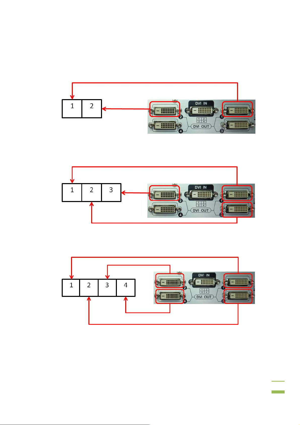
3.2 Panel Setup Options
The iVW-UD322videl wall controller supportspanel setup as shown in the subsections
below. Dark black sections indicate the panels for the installation, and the bold number
indicate which video output.
3.2.1 2 x 2
To setup four monitors as a 2 by 2 array, connect the monitors as shown below.
11
Page 19
iVW-UD322iVW-UD322 Video Wall Controller
3.2.2 2 x 1
To setup two monitors horizontally, connect the monitors as shown below.
3.2.3 3 x 1
To setup three monitors horizontally, connect the monitors as shown below.
3.2.4 4 x 1
To setup four monitors horizontally, connect the monitors as shown below.
12
Page 20

iVW-UD322iVW-UD322 Video Wall Controller
3.2.5 1 x 3
To setup three monitors vertically, connect the monitors as shown below.
3.2.6 1 x 4
To setup four monitors vertically, connect the monitors as shown below.
3.3 Install LCD Panels
The monitors should be installed in one of the configurations shown in the previous
section. Recommended installation procedures are to:
13
Page 21

iVW-UD322iVW-UD322 Video Wall Controller
Use all identical monitors
* Recommand to use monitors without control buttons around side of the
bezel, otherwise the buttons will be blocked by other panels
Minimize gaps between panels for the best image
Maintain consistent horizontal gaps between monitors
Maintain consistent vertical gaps between monitors
3.4 Mount the video wall controller
The iVW-UD322video wall controller must be placed on a table, desk or other firm surface.
Optionally, the iVW-UD322 can be mounted using the included mounting brackets. The
installation location must be:
Out of direct sunlight
Without anything on top of it
On a firm surface
Away from moisture and liquids
Figure 3-1: Mounting Brackets
14
Page 22

iVW-UD322iVW-UD322 Video Wall Controller
3.5 Connect Cables
The cables that need to be attached are listed below:
Video input cable(Dual-link DVI) – from the video source or computer
Video output cables – attached to the LCD panels. Make sure the cables are
connected to the correct monitors securely.
Power cable – from the power adapter
3.5.1 Connect the DVI Cables
To connect the DVI cables to the video box, follow the instructions below.
Step 1: Attach the included DVI cable to the DVI input on the video wall controller and
the DVI output on the video source (usually the graphic card of computer).
Step 2: Attach the DVI cables from the video wall controller DVI outputs to the monitors.
Attach the DVI cables as shown in Section 3.2: Panel Setup Options. Step 2:
Figure 3-2: iVW-UD322 Video Input
3.5.2 Connect the iVW-UD322 to the Power Supply
Connect the included AC adaptor into an AC power supply then connect the DC plug to
the video wall controller.
Turn oniVW-UD322by using the power switch located at the back panel.
15
Page 23
iVW-UD322iVW-UD322 Video Wall Controller
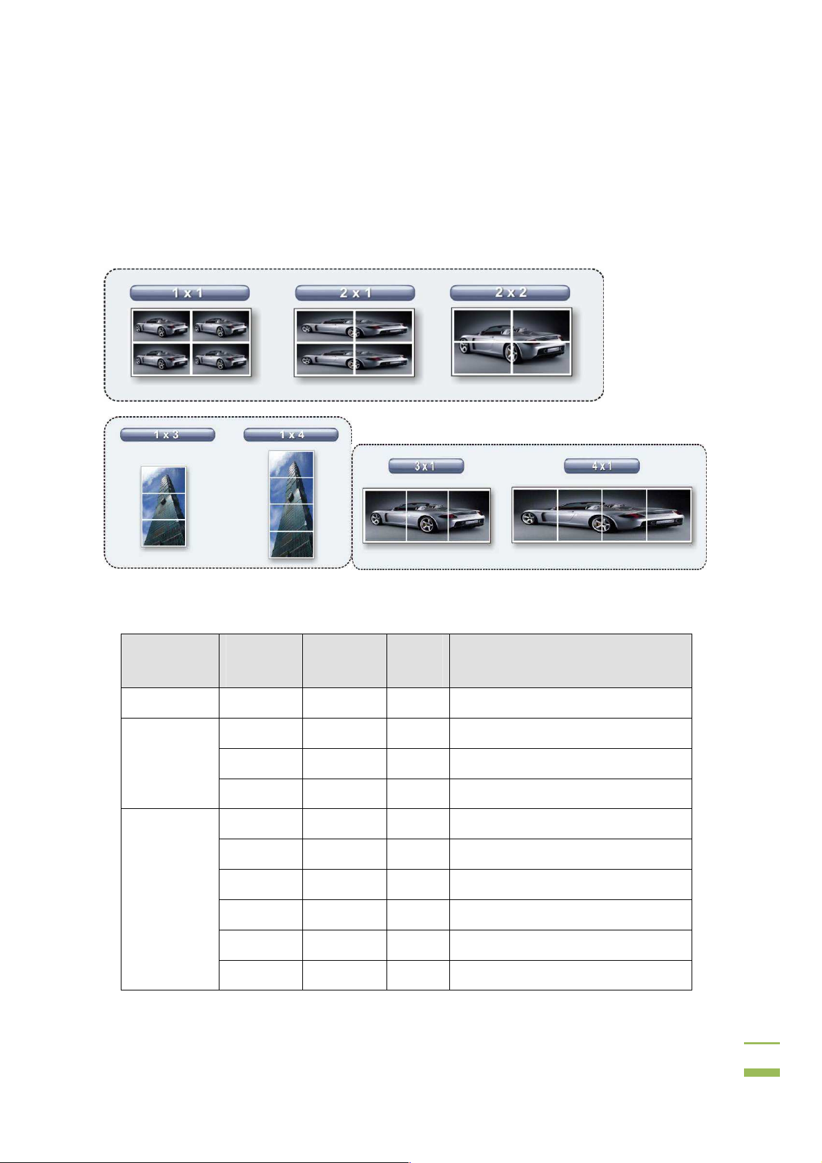
3.6 Resolution and Display Mode Charts
The display modes are automatically set according to the input resolution. The input and
output resolutions for iVW-UD322 are shown in the following subsections.
Figure 3-3: Display Modes
Mode
1x1 1024x768 1024x768 60 4:3
2x1
2x2
Input
Resolution
2560x1024 1280x1024 60 5:4
3840x1080 1920x1080
3840x1200 1920x1200
2048x1536 1024x768
2560x2048 1280x1024
2560x1440 1280x720
2560x1600 1280x800
2720x1536 1360x768
Output
Resolution
Vertical
Hz
60
60
60
60
60
60
60
Monitor Ratio / Notes
16:9
16:10
4:3
5:4
16:9
16:10
16:9
3840x2880 1920x1440
60
4:3
16
Page 24

iVW-UD322iVW-UD322 Video Wall Controller
Mode
4x1
Input
Resolution
3840x2160 1920x1080 60 16:9
3840x2400 1920x1200
2560x1920 1280x960 60
1280x960 640x480 60
3392x1920 1696x960 60
1696x960 848x480
2732x1536 1366x768 60 16:9
3392x480 848x480
3200x600 800x600 60 4:3
3840x600 960x600
Output
Resolution
Vertical
Hz
60
60
60
60
Monitor Ratio / Notes
16:10
As the master ofother iVW-UD322s
when casecading
As the slave controller when
casecading
As the master ofother iVW-UD322s
when casecading
As the slave controller when
casecading
16:9
16:10
1x4
3x1
1x3
4094x768 1024x768 60 4:3
1024x3072 1024x768
1280x3200 1280x800 60 16:10
1280x4095 1280x1024
1360x3072 1360x768 60 16:9
1366x3072 1366x768
3072x768 1024x768 60 4:3
3840x800 1280x800
3840x1024 1280x1024 60 5:4
4080x768 1360x768
1024x2304 1024x768 60 4:3
1280x2400 1280x800
60
60
60
60
60
60
4:3
5:4
16:9
16:10
16:9
16:10
17
Page 25

iVW-UD322iVW-UD322 Video Wall Controller
Mode
Input
Resolution
1280x3072 1280x1024 60 5:4
1360x2304 1360x768
1366x2304 1366x768 60 16:9
Output
Resolution
Vertical
Hz
60
Monitor Ratio / Notes
16:9
3.7 Setting Video Wall Controller and Graphics Card Resolution
To setup the resolution on the graphics card and on the video wall controller, follow the
instructions below.
Step 3: Turn on the video wall controller.
Step 4: Turn on the computer.
Step 5: The computer will automatically detect the video wall controller as a display.
Step 6: Set the required output resolution on the video wall controller
Step 7: Check the input resolution on the video wall controller and look up in the
setting table above. If the resolution is not listed, then correct the settings
manually to the nearest mode in the display mode list as shown in the section
below. Step 0:
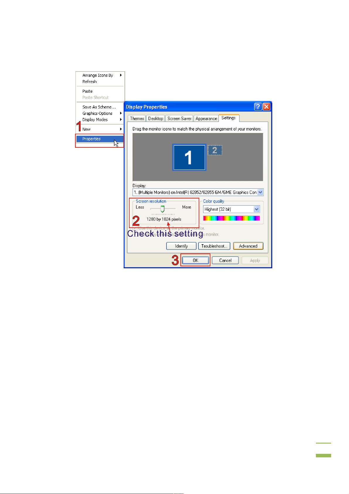
3.7.1 Setting Adjustment Troubleshooting (Manual Adjustment)
If the graphics card settings do not adjust automatically after adjusting the video wall
controller, follow these steps to fix the problem.
Step 1: Restart the computer. Some graphics cards don't support the correct detection
on the video wall controllerconnected at runtime and a system restart is
required.
Step 2: After restarting, check the output resolution. Right-click on the desktop and
select "Properties".
18
Page 26
iVW-UD322iVW-UD322 Video Wall Controller
Figure 3–4: Video Card Output Resolution
Step 3: Select the "Advanced" video card setting.
Step 4: Uncheck "Hide modes that this monitor cannot display". Step 0:
19
Page 27

iVW-UD322iVW-UD322 Video Wall Controller
Figure 3–5: Don't Hide Display Modes not supported by the monitor
3.8 Bezel Compensation
The bezel compensation setting compensates for the gaps between monitors in the video
wall array. The bezel compensation sizes the image slightly larger than the visible screen
to make the images on adjacent monitors line-up correctly.
The bezel settings are set using the smartOSD (Section 4.1) or OSD menu (Section 4.1).
20
Page 28

iVW-UD322iVW-UD322 Video Wall Controller
4 OSD Functions
Chapter
4
21
Page 29
UD322 Video Wall Controller
Display (
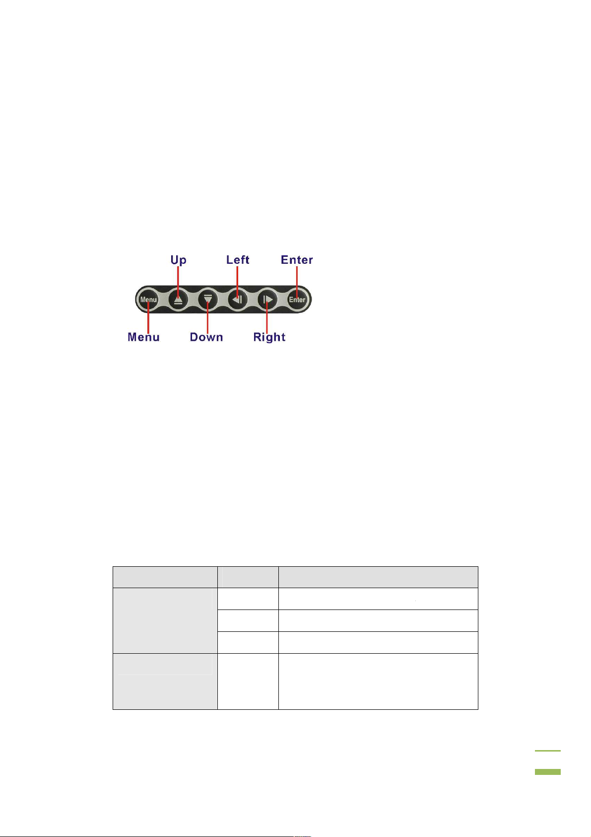
The OSD menu functions are described below.
Customer can control iVW
: OSD Buttons
. Enters the OSD, selects items and sets the new values entered.
. Moves the selection le
. Moves the selection right.
. Moves the selection up.
. Moves the selection down.
No function for this model
The subsections below cover the layout and use of the OSD. The table below shows the
OSD menu structure.
D by operating the buttons on front
ON and OFF
the link between the master
mask value and the
iVW-UD322iVW-
4.1 On Screen
4.1.1 OSD Buttons
panel as below
Figure 4-1
Menu
Left
OSD)
-UD322 through the OS
ft.
Right
Up
Down
Enter.
4.1.2 OSD Menu
Menu
Mask Control
Link Control
.
Options Description
MASK Toggles the mask function
X Set the horizontal mask value
Y Set the vertical mask value
LINK Enable/disable
video wall controller
slave controller's value
22
Page 30

iVW-UD322iVW-UD322 Video Wall Controller
Menu Options Description
Slave Mask Setting
(Note: These settings
can only be changed
while Link function is
turned off and Scan
function is turned on)
Settings OUT Set the output resolution
Warning Change
Information OUT Shows the output resolution
Sync and Power No SYNC
DVI DVI 1-4: Update linked slave controllers’
settings
DVI x: Update setting for an individual slave
controller when link is off.
X Setthe horizontal mask value
Y Setthe vertical mask value
MODE Set the output mode
Warns that the output resolution on the
Setting
IN Shows the input resolution
Pwr Off
SYNC Enable/disablethe synchronization between
video source must be changed.
Time to enter stand-by mode when there is
no video signal input
video wall controllers with fiber optical cable.
(iVW-UD322F only)
SCAN Toggles the scan function between the
master video wall controller and the slave
video wall controllers
Version Information FPGA Version number of one FPGA chip
CPLD Version number of the CPLD chip
FW Firmware version number
Model information Name Displays the model name
SN Displays the serial number
Table 4-1: OSD Menu Structure
23
Page 31

iVW-UD322iVW-UD322 Video Wall Controller
4.1.2.1 Mask Control
Mask control compensates for the gaps between monitors by displaying the images
slightly larger than the visible screen.
Figure 4-2: Mask Control
Mask
Enable / disable the mask function. With the mask function on, the image is adjusted to
compensate for gaps between monitors in the video wall.
Available selections:
Off
On
Right
Left
Top
Buttom
X
Adjusts the value of compensation from left to right.
Y
Adjusts the value of compensation from top to bottom.
24
Page 32

iVW-UD322iVW-UD322 Video Wall Controller
4.1.2.2 Link Control
Link control allows the master controller to automatically adjust the mask settings of the
attached slave controllers.
Figure 4-3: Link Control
LINK
This setting toggles the link setting on and off.
Off: When adjusting the mask of the master video wall controller, the mask of
the slave video wall controllers will not be adjusted
On: When adjusting the mask of the master video wall controller, the mask of
the slave video wall controllers will automatically be adjusted at the same time
25
Page 33

iVW-UD322iVW-UD322 Video Wall Controller
4.1.2.3 Slave Mask Setting
The slave mask setting shows the mask setting on the slave video boxes.
Figure 4-4: Slave Mask Setting
DVI
This setting indicates which slaves settings are shown.
DVI 1-4
DVI 1
DVI 2
DVI 3
DVI 4
/X
Displays the horizontal bezel setting of the slave controller.
/Y
Displays the vertical bezel setting of the slave controller.
Mask link is on, and all slaves have the same setting
Mask link is off. The first slave controller's settings are shown
Mask link is off. The second slave controller's settings are shown
Mask link is off. The third slave controller's settings are shown
Mask link is off. The fourth slave controller's settings are shown
26
Page 34

iVW-UD322iVW-UD322 Video Wall Controller
4.1.2.4 Settings
This menu shows the output resolution of the attached monitors.
Figure 4-5: Settings
OUT
This setting is the output resolution to the attached monitor or slave controller.
MODE
This setting shows the video output mode of the video box.
1 x 1
2 x 1
2 x 2
4 x 1
3 x 1
1 x 4
1 x 3
Clone mode
Vertical replication mode
2 x 2 video array
4 x 1 video array
3 x 1 video array
1 x 4 video array
1 x 3 video array
27
Page 35

iVW-UD322iVW-UD322 Video Wall Controller
4.1.2.5 Warning
Indicates that the output resolution on the computer should be adjusted to the shown
value.
Figure 4-6: Warning
Change Setting
Shows the value that the computer video output should be set to.
4.1.2.6 Information
The information menu shows the current input and output resolutions.
Figure 4-7: Information
28
Page 36

iVW-UD322iVW-UD322 Video Wall Controller
OUT
Displays the current output resolution.
IN
Displays the current input resolution
4.1.2.7 Sync and Power
The sync and power menu toggles sync and turns the power on and off.
Figure 4-8: Sync and Power
No SYNC Pwr Off
Timeout setting before entering stand-by mode when there is no video signal input
Never
5 sec
10 sec
30 sec
29
Page 37

iVW-UD322iVW-UD322 Video Wall Controller
SYNC
Enable/disable the synchronization between video wall controllers with fiber optical cable.
(iVW-UD322F only)
SCAN
Toggles the scan function between the master video wall controller and the slave video
wall controllers. Video wall controller will scan the devices connecting to DVI output ports
only when the SCAN option turns on.
The default setting is off.
4.1.2.8 Firmware Information
The firmware information screen shows the hardware versions of the onboard chips.
Figure 4-9: Firmware Information
FPGA
Shows the current version of the FPGA chip.
CPLD
Shows the current version of the CPLD chip.
30
Page 38

iVW-UD322iVW-UD322 Video Wall Controller
FW
Displays the current firmware version.
4.1.2.9 Serial Number
The serial number page shows the model name and serial number of the video wall
controller.
Figure 4-10: Serial Number
Model Name
The first line displays the model name.
SN
Theserial number is listed in two lines
31
Page 39

UD322 Video Wall Controller
Remote Control
has an optional
shows the remote control and its function keys.
: Remote Control
to Factory Default Settings
wall controller
sequence described below. Any custom settings will be lost during this process.
Up
The OSD displays a message that the settings have been reset.
: Reset to Factory Defaults
remote control for easy configuration of OSD settings.
. Enters the OSD, selects items and sets the
settings by
Up
” buttons simultaneously fo
iVW-UD322iVW-
4.1.3
The iVW-UD322
491H491H
Figure 4-11
Figure 4-11
4.1.4 Reset
The video
Power. Turns the controller on and off.
Menu
newvalues entered.
Left. Moves the selection left.
Right. Moves the selection right.
Up. Moves the selection up.
Down. Moves the selection down.
Enter. Exits from any menu.
can be reset to the factory default
using the key
Step 1: Push the “
Step 2:
Figure 4-12
”, “Down” and “Enter
r a few seconds.
Step 0:
32
Page 40

iVW-UD322iVW-UD322 Video Wall Controller
4.2 SmartOSD
iNDSSmartOSD is a powerfulmanagement software solution for managing video wall
controllerswith PCs under popular Microsoft Windows environment.
SmartOSD provides a more flexible wayon controlling the video wall controller and monitor
settings. By using SmartOSD, the screen output screen resolution and mask size can be
adjusted throughthesingle Dual-link DVI cable between PC and the video wall controller
The SmartOSDis compatible with the following operating systems.
Windows XP
Windows Vista
Windows 7
Windows 2003
Windows 2008
4.2.1 Installing SmartOSD
To install the software, please follow the steps below:
Step 1: Double-click on the “VWBOX SmartOSD” file to start the installation process. (錯錯錯錯
誤誤誤誤! 找不
找不到參照來源
到參照來源
找不找不
到參照來源到參照來源
。。。。
).
Figure 4-13: SmartOSDinstallation program
33
Page 41

iVW-UD322iVW-UD322 Video Wall Controller
Step 2: Click the “Allow” option if the security warning appears in Windows Vista or
Windows 7.
Step 3: The welcome screen appears as below.
Figure 4-14: SmartOSD Welcome Screen
Step 4: Click N
EXT
to continue.
34
Page 42

iVW-UD322iVW-UD322 Video Wall Controller
Step 5: The Select Destination Folder window appears (Figure 4-15).Change the
installation directory if required.
Click N
Figure 4-15: SmartOSD Installation Directory
EXT
to continue
Step 6: The program is now ready to install. Click “Install” to continue(Figure 4-15).
Figure 4-16: SmartOSDReady to Install
35
Page 43

iVW-UD322iVW-UD322 Video Wall Controller
Step 7: Specify a new name or folder for the Start Menu entry if required.
Click N
Step 8: The Additional Tasks window appears (Figure 4-17).
Figure 4-17: SmartOSDAdditional Tasks
EXT
to continue.
Step 9: Check the extra items that should be added (optional). Click N
Step 10: The Ready to Installdialog will show be displayed (Figure 4-18).
EXT
to continue.
36
Page 44

iVW-UD322iVW-UD322 Video Wall Controller
Figure 4-18: SmartOSDReady to Install
Step 11: Confirm the installation by clicking I
Step 12: The Installation Progressdialogwill display the progress of the software
installation (Figure 4-19).
NSTALL
in the screen above.
Figure 4-19: SmartOSD Installing
37
Page 45

iVW-UD322iVW-UD322 Video Wall Controller
Step 13: The following dialog is displayed when the installation is completed
Figure 4-20: SmartOSD Installation Complete
Step 14: Click F
INISH
to close the installation wizard. Step 0:
38
Page 46

iVW-UD322iVW-UD322 Video Wall Controller
4.2.2 Using SmartOSD
The following table describe the complete functions of SmartOSD(Table 4-2).
Menu Options
PC Setting Interface Selection
Master Control
Panel
Slave Control
Panel
Master OSD Data Mask On/Off
About Company Contact Details
Table 4-2: SmartOSD Menu Structure
Mask Control
Display Resolution
Display Mode
Mask Setting
Selection
Mask Selection
Mask Settings
Mask X
Mask Y
Input Resolution
Display Mode
Output Resolution
Sync
39
Page 47

iVW-UD322iVW-UD322 Video Wall Controller
4.2.2.1 PC Setting
The PC Setting page sets the command port to use for data communication between the
video box and the computer.
DVI
Identify
S/N
Figure 4-21: smartOSD PC Setting
Selects the DVI input signal.
Detect and identify the video wall controller on the DVI link.
Displays the controller's serial number.
40
Page 48

iVW-UD322iVW-UD322 Video Wall Controller
4.2.2.2 Master Control Panel
The control panel page presents all the adjustable settings for the video wall controller.
Figure 4-22: SmartOSD Master Control Panel
Mask Control
The Mask Control options allow the images to be adjusted to compensate for the gaps
between monitors in the video array.
Off The images are shown without any adjustments
On The value of X and the value of Y can be adjusted to compensate for
gaps between monitors (for single controller)
MR The right side is fixed and the left side changes when adjustments
are made (for right side controller in the dual controller configuration)
ML The left side is fixed and the right side changes when adjustments
are made (for left side controllerin the dual controller configuration)
41
Page 49

iVW-UD322iVW-UD322 Video Wall Controller
MU The top side is fixed and the bottom side changes when adjustments
are made (for top side controller in the dual controller configuration)
MD The bottom side is fixed and the top side changes when adjustments
are made (for bottom side controller in the dual controller
configuration)
Power Control
Turns the power on and off.
Value of X
The Value of X sets the horizontal bezel compensation.
Value of Y
The Value of Y sets the vertical bezel compensation.
Output Resolution
This option sets the video output resolutionas shown in
Section 3.6: Resolution and Display Mode Charts.
Output Mode
This option sets the output mode of the video wall controller as shown
inSection 3.6: Resolution and Display Mode Charts
Sync
The Sync option sets the frame timing synchronization between multiple video wall
controllers.
On
Off
Controlleris set to synchronize with other controllers
Controlleris not set to synchronize with other controllers
42
Page 50

iVW-UD322iVW-UD322 Video Wall Controller
4.2.2.3 Slave Control Panel
Figure 4-23: SmartOSD Slave Control Panel
Mask Control Link
Enable/disable the mask link between the master and slaves.
When the mask control link has been disabled, the slave controllers can be managed by
the following options.
DVI Number
DVI number selects the target slave controller to be managed.
Mask Control
The Mask Control options allow the images to be adjusted to compensate for the gaps
between monitors in the video array.
Off The images are shown without any adjustments
43
Page 51

iVW-UD322iVW-UD322 Video Wall Controller
On The value of X and the value of Y can be adjusted to compensate for
gaps between monitors (for single controller)
MR The right side is fixed and the left side changes when adjustments
are made (for right side controller in the dual controller configuration)
ML The left side is fixed and the right side changes when adjustments
are made (for left side controller in the dual controller configuration)
MU The top side is fixed and the bottom side changes when adjustments
are made (for top side controller in the dual controller configuration)
MD The bottom side is fixed and the top side changes when adjustments
are made (for bottom side controller in the dual controller
configuration)
Mask X and Y Setting
Adjusts the horizontal (X) and vertical (Y) mask settings.
44
Page 52

iVW-UD322iVW-UD322 Video Wall Controller
4.2.2.4 Master Data
The Master Data menu displays the current settings of the master video wall controller.
Figure 4-24: SmartOSD Master Data
45
Page 53

iVW-UD322iVW-UD322 Video Wall Controller
4.2.2.5 About Page
The About Page shows general information about the SmartOSD.
Figure 4-25: SmartOSD About Page
46
Page 54

iVW-UD322iVW-UD322 Video Wall Controller
5 Troubleshooting and
Chapter
5
5.1 Maintenance Overview
NOTE:
There are no user-serviceable parts inside. Make sure to carefully
follow all the instructions in this section to diagnose any problems. If
the problem persists, email ds_sales@indstech.com for help from an
authorized sales representative
5.2 Troubleshooting
This section provides some simple troubleshooting suggestions.
5.2.1 No Image on One Monitor
Maintenance
If there is no image on one monitor, follow these steps to remedy the problem.
47
Page 55

iVW-UD322iVW-UD322 Video Wall Controller
5.2.1.1 Check Monitor Power
Step 1: Make sure the monitor is turned on.
Step 2: Check the power source for the monitor.
Step 3: Make sure the power source has the correct power rating (check panel
specifications for details).
Step 4: Make sure the LCD panel power cables are properly secured to the monitor and
to the power source.Step 0:
5.2.1.2 Check Monitor Video Connection
Make sure the video cable is linkedproperly.
Step 1: Make sure a working DVIcablewith length less than 5 M is connected to
iVW-UD322.
Step 2: Fasten the screws on the connector of video cable.Step 0:
5.2.2 No Image on Two or More Monitors
If there is no image on more than one of the panels, then repeat the steps in Section 5.2.1
for all of the monitors in the array.
5.2.3 No Image on Any Monitor
If no image displays on any monitors, repeat the steps in Section 5.2.1 for all the monitors
in the array, then try the following additional steps.
5.2.3.1 Check Video Wall Controller Power
Make sure that the controller is powered on.
Step 1: Ensure the power supply is connected to the power source.
Step 2: Make sureiVW-UD322 is connected to the power adaptor.Step 0:
48
Page 56

iVW-UD322iVW-UD322 Video Wall Controller
5.2.3.2 Check Source Video Connection
Make sure the video cable is linkedproperly.
Step 1: Make sure a Dual-link DVIcablewith length less than 5 M is connected between
PC andiVW-UD322.
Step 2: Fasten the screws on the connector of video cable.Step 0:
49
 Loading...