

Page 1

IEI Technology Corp.
User Manual
V
IVCE-C608/IVCE-C604/IVCME-C604 Capture Card
MODEL:
IVCE-C608/IVCE-C604/IVCME-C604
ideo Capture Card with PCIe/PCIe Mini Interface
8-Channel/4-Channel Input, RoHS Compliant
Rev. 1.00 – 6 February, 2012
Page 1
Page 2
Date Version Changes
6 February, 2012 1.00 Initial release
IVCE-C608/IVCE-C604/IVCME-C604 Capture Card
Revision
Page 2
Page 3

IVCE-C608/IVCE-C604/IVCME-C604 Capture Card
Copyright
COPYRIGHT NOTICE
The information in this document is subject to change without prior notice in order to
improve reliability, design and function and does not represent a commitment on the part
of the manufacturer.
In no event will the manufacturer be liable for direct, indirect, special, incidental, or
consequential damages arising out of the use or inability to use the product or
documentation, even if advised of the possibility of such damages.
This document contains proprietary information protected by copyright. All rights are
reserved. No part of this manual may be reproduced by any mechanical, electronic, or
other means in any form without prior written permission of the manufacturer.
TRADEMARKS
All registered trademarks and product names mentioned herein are used for identification
purposes only and may be trademarks and/or registered trademarks of their respective
owners.
Page 3
Page 4

IVCE-C608/IVCE-C604/IVCME-C604 Capture Card
Table of Contents
1 INTRODUCTION........................................................................................................ 10
1.1 OVERVIEW.................................................................................................................11
1.1.1 Model Variations.............................................................................................. 12
1.1.2 Features ........................................................................................................... 12
1.1.3 Software Support.............................................................................................. 12
1.2 OVERVIEW PHOTO.................................................................................................... 13
1.2.1 IVCE-C608 Overview ...................................................................................... 13
1.2.2 IVCE-C604 Overview ...................................................................................... 14
1.2.3 IVCME-C604 Overview................................................................................... 15
2 PRODUCT SPECIFICATIONS................................................................................. 16
2.1 SPECIFICATIONS ....................................................................................................... 17
2.1.1 Video Interfaces................................................................................................ 17
2.1.2 Video Processing.............................................................................................. 18
2.1.3 Audio Processing ............................................................................................. 19
2.1.4 System Requirements........................................................................................ 19
2.1.5 Mechanical and Environmental Specifications................................................ 20
2.2 DIMENSIONS............................................................................................................. 21
2.2.1 IVCE-C608 Dimension Drawing..................................................................... 21
2.2.2 IVCE-C604 Dimension Drawing..................................................................... 22
2.2.3 IVCME-C604 Dimension Drawing.................................................................. 23
3 PACKING LIST........................................................................................................... 24
3.1 ANTI-STATIC PRECAUTIONS...................................................................................... 25
3.2 UNPACKING PRECAUTIONS....................................................................................... 25
3.3 PACKING LIST........................................................................................................... 26
3.4 OPTIONAL ITEMS...................................................................................................... 28
4 CONNECTORS AND JUMPERS.............................................................................. 29
4.1 VIDEO CAPTURE CARD CONNECTOR DIAGRAMS........................................................ 2
4.1.1 IVCE-C608 Pinouts ........................................................................................... 2
Page 4
Page 5

IVCE-C608/IVCE-C604/IVCME-C604 Capture Card
4.1.1.1 IVCE-C608 Switch (SW1) ......................................................................... 3
4.1.1.2 IVCE-C608 LED Screen (LED2)............................................................... 3
4.1.1.3 IVCE-C608 LED Indicators (LED1).......................................................... 3
4.1.1.4 IVCE-C608 Reset Input Connector (CN4)................................................. 4
4.1.1.5 IVCE-C608 Reset Output Connector (CN5) .............................................. 4
4.1.1.6 IVCE-C608 Video/Audio Input/Output Connector (J1)............................. 4
4.1.1.7 IVCE-C608 GPIO Connector (CN2, CN3) ................................................ 5
4.1.2 IVCE-C604 Pinouts ........................................................................................... 6
4.1.2.1 IVCE-C604 Switch (SW1) ......................................................................... 7
4.1.2.2 IVCE-C604 LED Screen (LED2)............................................................... 7
4.1.2.3 IVCE-C604 LED Indicators (LED1).......................................................... 7
4.1.2.4 IVCE-C604 Reset Input Connector (CN4)................................................. 8
4.1.2.5 IVCE-C604 Reset Output Connector (CN5) .............................................. 8
4.1.2.6 IVCE-C604 Video/Audio Input/Output Connector (J1)............................. 8
4.1.2.7 IVCE-C604 GPIO Connector (CN3).......................................................... 9
4.1.3 IVCME-C604 Pinouts...................................................................................... 10
4.1.3.1 IVCME-C604 Video/Audio Input Connector (CN1).................................11
4.1.3.2 IVCME-C604 GPIO Connector (CN2) .....................................................11
5 HARDWARE INSTALLATION................................................................................. 12
5.1 ANTI-STATIC PRECAUTIONS...................................................................................... 13
5.2 INSTALLATION CONSIDERATIONS.............................................................................. 14
5.3 SYSTEM REQUIREMENT............................................................................................ 15
5.4 IVCE-C608/IVCE-C604 HARDWARE INSTALLATION .............................................. 15
5.4.1 Hardware Installation Procedures................................................................... 15
5.4.2 Video Capture Card Installation...................................................................... 15
5.4.3 Install the Reset Cables (Optional).................................................................. 16
5.4.4 Install the GPIO Card (Optional).................................................................... 17
5.4.4.1 GPIO Card Pinouts ................................................................................... 18
5.4.5 Set the Rotary Switch ID Settings .................................................................... 19
5.4.6 Video and Audio Input Connection .................................................................. 20
5.4.7 Video Output Connection................................................................................. 21
5.5 IVCME-C604 HARDWARE INSTALLATION............................................................... 22
5.5.1 Hardware Installation Procedures................................................................... 22
5.5.2 Video Capture Card Installation...................................................................... 23
Page 5
Page 6

5.5.3 Video and Audio Input Connection .................................................................. 23
5.5.4 Install the GPIO Card (Optional).................................................................... 25
6 SOFTWARE AND DRIVER....................................................................................... 26
6.1 OVERVIEW................................................................................................................ 27
6.2 DRIVER AND APPLICATION INSTALLATION................................................................ 27
6.2.1 FFDShow Installation...................................................................................... 31
6.2.2 Uninstall Driver and Application .................................................................... 33
6.3 IEI VIDEO CAPTURE TEST SUITE.............................................................................. 34
6.3.1 Video Capture................................................................................................... 34
6.3.2 Video Bypass (IVCE-C608 and IVCE-C604 Only) .......................................... 40
6.3.3 Video Out (IVCE-C608 and IVCE-C604 Only) ............................................... 42
6.3.4 Other Functions............................................................................................... 44
6.3.4.1 Frame Rate................................................................................................ 45
6.3.4.2 Color Control............................................................................................ 46
IVCE-C608/IVCE-C604/IVCME-C604 Capture Card
6.3.4.3 GPIO......................................................................................................... 47
6.3.4.4 Watchdog T imer (WDT)........................................................................... 48
6.3.4.5 General Information.................................................................................. 49
A HAZARDOUS MATERIALS DISCLOSURE......................................................... 50
A.1 HAZARDOUS MATERI AL DISCLOSURE TABLE FOR IPB PRODUCTS CERTIFIED AS
ROHS COMPLIANT UNDER 2002/95/EC WITHOUT MERCURY ....................................... 51
Page 6
Page 7

IVCE-C608/IVCE-C604/IVCME-C604 Capture Card
List of Figures
Figure 1-1: IVCE-C608/IVCE-C604/IVCME-C604 Capture Cards ..............................................11
Figure 1-2: IVCE-C608 Overview.................................................................................................13
Figure 1-3: IVCE-C604 Overview.................................................................................................14
Figure 1-4: IVCME-C604 Overview..............................................................................................15
Figure 2-1: IVCE-C608 Dimension Drawing...............................................................................21
Figure 2-2: IVCE-C604 Dimension Drawing...............................................................................22
Figure 2-3: IVCME-C604 Dimension Drawing ............................................................................23
Figure 4-1: IVCE-C608 Connectors and Pinouts (pin numbers in red).....................................3
Figure 4-2: IVCE-C604 Connectors and Pinouts (pin numbers in red).....................................7
Figure 4-3: IVCME-C604 Connectors and Pinouts (pin numbers in red)................................10
Figure 5-1: IVCE-C608 and IVCE-C604 Installation...................................................................16
Figure 5-2: Cascade Reset Connection......................................................................................17
Figure 5-3: GPIO Cable for IVCE-C608 and IVCE-C604.............................................................18
Figure 5-4: GPIO Card Pinouts....................................................................................................18
Figure 5-5: LED Screen and ID Rotary Switch...........................................................................19
Figure 5-6: Video and Audio Input Connection.........................................................................20
Figure 5-7: Video Output Connection.........................................................................................22
Figure 5-8: IVCME-C604 Installation...........................................................................................23
Figure 5-9: Video and Audio Input Connection (IVCME-C604)................................................24
Figure 5-10: GPIO Cable for IVCME-C604 ..................................................................................25
Figure 6-1: Autorun Startup Screen............................................................................................27
Figure 6-2: Driver Directory Icon.................................................................................................28
Figure 6-3: Driver Installation - Select Card ID..........................................................................29
Figure 6-4: Windows Warning Window......................................................................................29
Figure 6-5: Driver Installing.........................................................................................................30
Figure 6-6: Driver Installation Complete ....................................................................................30
Figure 6-7: Device Manager.........................................................................................................31
Figure 6-8: IEI Video Capture Test Suite Shortcut Icon............................................................31
Figure 6-9: FFDShow - VFW Configuration................................................................................32
Figure 6-10: FFDShow Video Encoder Configuration Window................................................32
Page 7
Page 8

Figure 6-11: Uninstall IEI Video Capture Test Suite (Start Menu)............................................33
Figure 6-12: Device Manager – Uninstall Driver........................................................................34
Figure 6-13: IEI Video Capture Test Suite..................................................................................35
Figure 6-14: Available Cards.......................................................................................................36
Figure 6-15: Capture Settings Window.......................................................................................36
Figure 6-16: Audio Preview Selection ........................................................................................38
Figure 6-17: Recording File Path Selection...............................................................................39
Figure 6-18: Start Video Capture.................................................................................................39
Figure 6-19: Capturing Video ......................................................................................................40
Figure 6-20: Video Out Window ..................................................................................................41
Figure 6-21: Video Out – By pass ...............................................................................................41
Figure 6-22: Video Out Window (Upper).....................................................................................43
Figure 6-23: Video Out Window (Bottom) ..................................................................................44
Figure 6-24: Frame Rate Window................................................................................................45
IVCE-C608/IVCE-C604/IVCME-C604 Capture Card
Figure 6-25: Color Settings..........................................................................................................46
Figure 6-26: GPIO Control ...........................................................................................................47
Figure 6-27: WDT Window ...........................................................................................................48
Figure 6-28: WDT Options for Multiple Cards............................................................................48
Figure 6-29: General Window......................................................................................................49
Figure 6-30: LED Function Test ..................................................................................................49
Figure 6-31: AES Check - Pass ...................................................................................................49
Page 8
Page 9

IVCE-C608/IVCE-C604/IVCME-C604 Capture Card
List of Tables
Table 1-1: IVCE-C608/IVCE-C604/IVCME-C604 Video Capture Card Models..........................12
Table 2-1: Video Interfaces..........................................................................................................17
Table 2-2: Video Processing........................................................................................................18
Table 2-3: Audio Processing.......................................................................................................19
Table 2-4: System Requirements................................................................................................19
Table 2-5: Mechanical and Environmental Specifications .......................................................20
Table 3-1: Packing List.................................................................................................................27
Table 3-2: Optional Items.............................................................................................................28
Table 4-1: IVCE-C608 Connectors.................................................................................................2
Table 4-2: IVCE-C608 Reset Input Connector Pinouts................................................................4
Table 4-3: IVCE-C608 Reset Output Connector Pinouts.............................................................4
Table 4-4: IVCE-C608 Video/Audio Input Connector Pinouts ....................................................5
Table 4-5: IVCE-C608 GPIO Connector Pinouts..........................................................................5
Table 4-6: IVCE-C604 Connectors.................................................................................................6
Table 4-7: IVCE-C604 Reset Input Connector Pinouts................................................................8
Table 4-8: IVCE-C604 Reset Output Connector Pinouts.............................................................8
Table 4-9: IVCE-C604 Video/Audio Input Connector Pinouts ....................................................9
Table 4-10: IVCE-C604 GPIO Connector Pinouts........................................................................9
Table 4-11: IVCME-C604 Connectors..........................................................................................10
Table 4-12: IVCME-C604 Video/Audio Input Connector Pinouts.............................................11
Table 4-13: IVCME-C604 GPIO Connector Pinouts...................................................................11
Table 6-1: Supported Resolutions..............................................................................................37
Page 9
Page 10

IVCE-C608/IVCE-C604/IVCME-C604 Capture Card
Chapter
1
1 Introduction
Page 10
Page 11
IVCE-C608/IVCE-C604/IVCME-C604 Capture Card
1.1 Overview
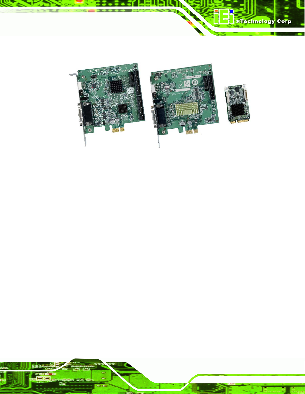
Figure 1-1: IVCE-C608/IVCE-C604/IVCME-C604 Capture Cards
The low power IVCE-C608/IVCE-C604/IVCME-C604 video capture cards are essential
surveillance system components. The IVCE-C608/IVCE-C604/IVCME-C604 video
capture cards are equipped with the high-performing Conexant video capture controllers
with up to eight video and audio input channels.
A software development kit (SDK) and a demo application are shipped with each card and
the flexible system architecture simplifies the integration of cameras, video signal
processing, storage and video management as well as security applications.
Page 11
Page 12
1.1.1 Model Variations
There are three video capture card models with different connecting interfaces. These
models are listed below:
Model Name Interface Video Input Audio Input
IVCE-C608/IVCE-C604/IVCME-C604 Capture Card
IVCE-C608
IVCE-C604
IVCME-C604
Table 1-1: IVCE-C608/IVCE-C604/IVCME-C604 Video Capture Card Models
PCIe 8 channels 8 channels
PCIe 4 channels 4 channels
PCIe Mini 4 channels 4 channels
1.1.2 Features
Some of the IVCE-C608/IVCE-C604/IVCME-C604 video capture card features are listed
below.
Low power
Multiple card support
Easy ID programming
PCIe/PCIe Mini connection interface
Software development kit (SDK)
Demo application
1.1.3 Software Support
IEI provides the following software support for the IVCE-C608/IVCE-C604/IVCME-C604:
Device Driver: for Windows XP or Windows 7
SDK: SDK and demo program with source code in C++
Page 12
Page 13

IVCE-C608/IVCE-C604/IVCME-C604 Capture Card
1.2 Overview Photo
The IVCE-C608/IVCE-C604/IVCME-C604 video capture cards have a wide variety of
peripheral interface connectors. The following sections give an overview of each model.
1.2.1 IVCE-C608 Overview
The IVCE-C608 comes with one Conexant CX25853 video capture controller, two GPIO
connectors, one rotary switch, LED indicators and one DB-26 video/audio connector. A
PCIe edge connector on the bottom of the capture card enables the IVCE-C608 to
interface with a motherboard or CPU card. An overview can be seen in
IVCE-C608 Overview.
Figure 1-2: IVCE-C608 Overview
Figure 1-2:
Page 13
Page 14

1.2.2 IVCE-C604 Overview
The IVCE-C604 comes with one Conexant CX25850 video capture controller, one GPIO
connector, one rotary switch, LED indicators and one DB-26 video/audio connector. A
PCIe edge connector on the bottom of the capture card enables the IVCE-C604 to
IVCE-C608/IVCE-C604/IVCME-C604 Capture Card
interface with a motherboard or CPU card. An overview can be seen in
IVCE-C604 Overview.
Figure 1-3: IVCE-C604 Overview
Figure 1-3:
Page 14
Page 15

IVCE-C608/IVCE-C604/IVCME-C604 Capture Card
1.2.3 IVCME-C604 Overview
The IVCME-C604 comes with one Conexant CX25854 video capture controlle r, one GPIO
connector and one video/audio connector. The PCIe Mini interface of the capture card
enables the IVCME-C604 to interface with a motherboard. An overview can be seen in
Figure 1-4: IVCME-C604 Overview.
Figure 1-4: IVCME-C604 Overview
Page 15
Page 16

IVCE-C608/IVCE-C604/IVCME-C604 Capture Card
Chapter
2
2 Product Specifications
Page 16
Page 17

IVCE-C608/IVCE-C604/IVCME-C604 Capture Card
2.1 Specifications
The following specifications are listed in the tables below:
Table 2-1: Video Interfaces
Table 2-2: Video Processing
Table 2-3: Audio Processing
Table 2-4: System Requirements
Table 2-5: Mechanical and Environmental Specifications
2.1.1 Video Interfaces
The following table lists detailed specifications for the interfaces on the three video
capture cards.
IVCE-C608 IVCE-C604 IVCME-C604
Video Input Channels
Video Input Format
Video Input Type
Audio Input Channels
Audio Input Connector
Video Output Channels
Video Output Type
PCI/PCIe
Alarm I/O
Card ID
LED Indicators
*API will be provided for users to define the LED function.
Eight Four Four
NTSC or PAL NTSC or PAL NTSC or PAL
BNC BNC BNC
Eight Four Four
RCA RCA RCA
Two Two N/A
BNC BNC N/A
PCIe x1 PCIe x1 PCIe Mini
Yes Yes Yes
Rotary switch selectable
with LED for ID indication
Red: self-defined*
Green: self-defined*
Amber: watchdog alarm
Table 2-1: Video Interfaces
Rotary switch selectable
with LED for ID indication
Red: self-defined*
Green: self-defined*
Amber: watchdog alarm
N/A
N/A
Page 17
Page 18

2.1.2 Video Processing
The following table lists detailed specifications for the video processing features on the
three video capture cards.
VIDEO PROCESSING IVCE-C608 IVCE-C604 IVCME-C604
IVCE-C608/IVCE-C604/IVCME-C604 Capture Card
Video Compression
Video Engine
NTSC
Resolution
PAL
NTSC
Frame
Rate
PAL
Software compression Software compression Software compression
One Conexant CX25853 One Conexant CX25850 One Conexant CX25854
720x480
720x240
640x480
640x240
352x240
320x240
160x120
720x576
720x288
352x288
Total 240fps @ D1 for
eight channels
Total 200fps @ D1 for
eight channels
720x480
720x240
640x480
640x240
352x240
320x240
160x120
720x576
720x288
352x288
Total 120fps @ D1 for
four channels
Total 100fps @ D1 for
four channels
720x480
720x240
640x480
640x240
352x240
320x240
160x120
720x576
720x288
352x288
Total 120fps @ D1 for
four channels
Total 100fps @ D1 for
four channels
Page 18
On-screen Display
Yes Yes Yes
Table 2-2: Video Processing
Page 19

IVCE-C608/IVCE-C604/IVCME-C604 Capture Card
2.1.3 Audio Processing
The following table lists detailed specifications for the audio processing features on the
three video capture cards.
AUDIO PROCESSING IVCE-C608 IVCE-C604 IVCME-C604
Audio Compression
Sampling rates (hardware
spec.)
Quantization (hardware
spec.)
Software compression Software compression Software compression
32 kHz
44.1 kHz
48 kHz
96 kHz
24-bit 24-bit 16-bit
32 kHz
44.1 kHz
48 kHz
96 kHz
8 kHz
16 kHz
32 kHz
44.1 kHz
48 kHz
Table 2-3: Audio Processing
2.1.4 System Requirements
The following table lists detailed system requirements for the three video capture cards.
SYSTEM REQUIREMENTS IVCE-C608 IVCE-C604 IVCE-C604
System
x86 compatible
computer
x86 compatible
computer
x86 compatible
computer
PCIe
Minimum Memory
Graphics
PCIe x1 lane
compatible with PCIe
x1, x4, x8 and x16
slots
512 MB 512 MB 512 MB
DirectX compatible
VGA card with YUV
overlay mode support
PCIe x1 lane
compatible with PCIe
x1, x4, x8 and x16
slots
DirectX compatible
VGA card with YUV
overlay mode support
PCIe Mini
DirectX compatible
VGA card with YUV
overlay mode support
Table 2-4: System Requirements
Page 19
Page 20

IVCE-C608/IVCE-C604/IVCME-C604 Capture Card
2.1.5 Mechanical and Environmental Specifications
The following table lists the dimensions, operating temperature and power consumption
for each model.
OTHERS IVCE-C608 IVCE-C604 IVCME-C604
Dimensions (mm)
Operating Temperature
Power Consumption
111.00 x 102.40 111.23 x 102.39 50.92 x 30.00
-5ºC – 65ºC,
non-condensing
5.3 W
(3.3V @1.39 A,
12V @0.06 A)
-5ºC – 65ºC,
non-condensing
3.51 W
(3.3V @0.9 A,
12V @0.045 A)
-5ºC – 65ºC,
non-condensing
1.65 W
(3.3V @500mA)
Table 2-5: Mechanical and Environmental Specifications
Page 20
Page 21

IVCE-C608/IVCE-C604/IVCME-C604 Capture Card
2.2 Dimensions
The dimensions for each model are listed in Table 2-5: Mechanical and Environmental
Specifications above. Detailed dimension drawings for each mode l are shown in the
sections below.
2.2.1 IVCE-C608 Dimension Drawing
The dimensions for the IVCE-C608 are listed below:
Length: 111.0 mm
Width: 102.4 mm
The dimensions are shown in
Figure 2-1: IVCE-C608 Dimension Drawing
Figure 2-1: IVCE-C608 Dimension Drawing.
Page 21
Page 22

IVCE-C608/IVCE-C604/IVCME-C604 Capture Card
2.2.2 IVCE-C604 Dimension Drawing
The dimensions for the IVCE-C604 are listed below:
Length: 111.23 mm
Width: 102.39 mm
The dimensions are shown in
Figure 2-2: IVCE-C604 Dimension Drawing.
Page 22
Figure 2-2: IVCE-C604 Dimension Drawing
Page 23

IVCE-C608/IVCE-C604/IVCME-C604 Capture Card
2.2.3 IVCME-C604 Dimension Drawing
The dimensions for the IVCME-C604 are listed below:
Length: 50.92 mm
Width: 30.00 mm
The dimensions are shown in
Figure 2-3: IVCME-C604 Dimension Drawing
Figure 2-3: IVCME-C604 Dimension Drawing.
Page 23
Page 24

IVCE-C608/IVCE-C604/IVCME-C604 Capture Card
Chapter
3
3 Packing List
Page 24
Page 25

IVCE-C608/IVCE-C604/IVCME-C604 Capture Card
3.1 Anti-static Precautions
WARNING:
Static electricity can destroy certain electronics. Make sure to follow the
ESD precautions to prevent damage to the product, and injury to the
user.
Make sure to adhere to the following guidelines:
Wear an anti-static wristband: Wearing an anti-static wristband can prevent
electrostatic discharge.
Self-grounding: Touch a grounded conductor every few minutes to discharge
any excess static buildup.
Use an anti-static pad: When configuring any circuit board, place it on an
anti-static mat.
Only handle the edges of the PCB: Don't touch the surface of the
motherboard. Hold the motherboard by the edges when handling.
3.2 Unpacking Precautions
When the IVCE-C608/IVCE-C604/IVCME-C604 is unpacked, please do the following:
Follow the antistatic guidelines above.
Make sure the packing box is facing upwards whe n opening.
Make sure all the packing list items are present.
Page 25
Page 26

3.3 Packing List
NOTE:
If any of the components listed in the checklist below are missing, do
not proceed with the installation. Contact the IEI reseller or vendor the
IVCE-C608/IVCE-C604/IVCME-C604 was purchased from or contact
an IEI sales representative directly by sending an email to
31sales@iei.com.tw.
The IVCE-C608/IVCE-C604/IVCME-C604 is shipped with the following components:
Quantity Item and Part Number Image
IVCE-C608/IVCE-C604/IVCME-C604 Capture Card
1 IVCE-C608/IVCE-C604/IVCME-C604
video capture card
1 Video and audio input cable
DB-26 to 8-channel video and 8-channel audio
(IVCE-C608 only)
1 Video and audio input cable
DB-26 to 4-channel video and 4-channel audio
(IVCE-C604 only)
1 Video and audio input cable
(IVCME-C604 only)
Page 26
Page 27
IVCE-C608/IVCE-C604/IVCME-C604 Capture Card
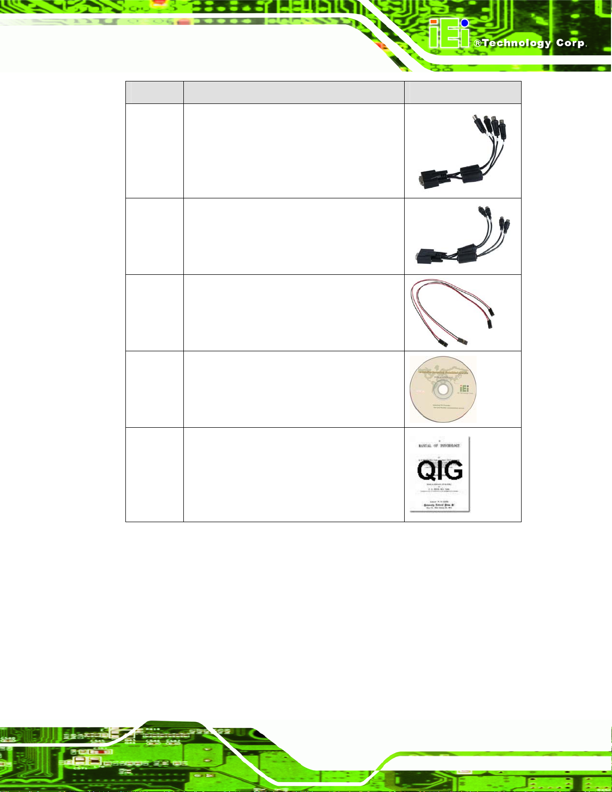
Quantity Item and Part Number Image
1 Video input cable
DB-9 to 4-channel BNC connector
(IVCME-C604 only)
1 Audio input cable
DB-9 to 4-channel RCA connector
(IVCME-C604 only)
2 Reset cable
(IVCE-C608 and IVCE-C604 only)
1 Utility CD
1 Quick installation guide
Table 3-1: Packing List
Page 27
Page 28
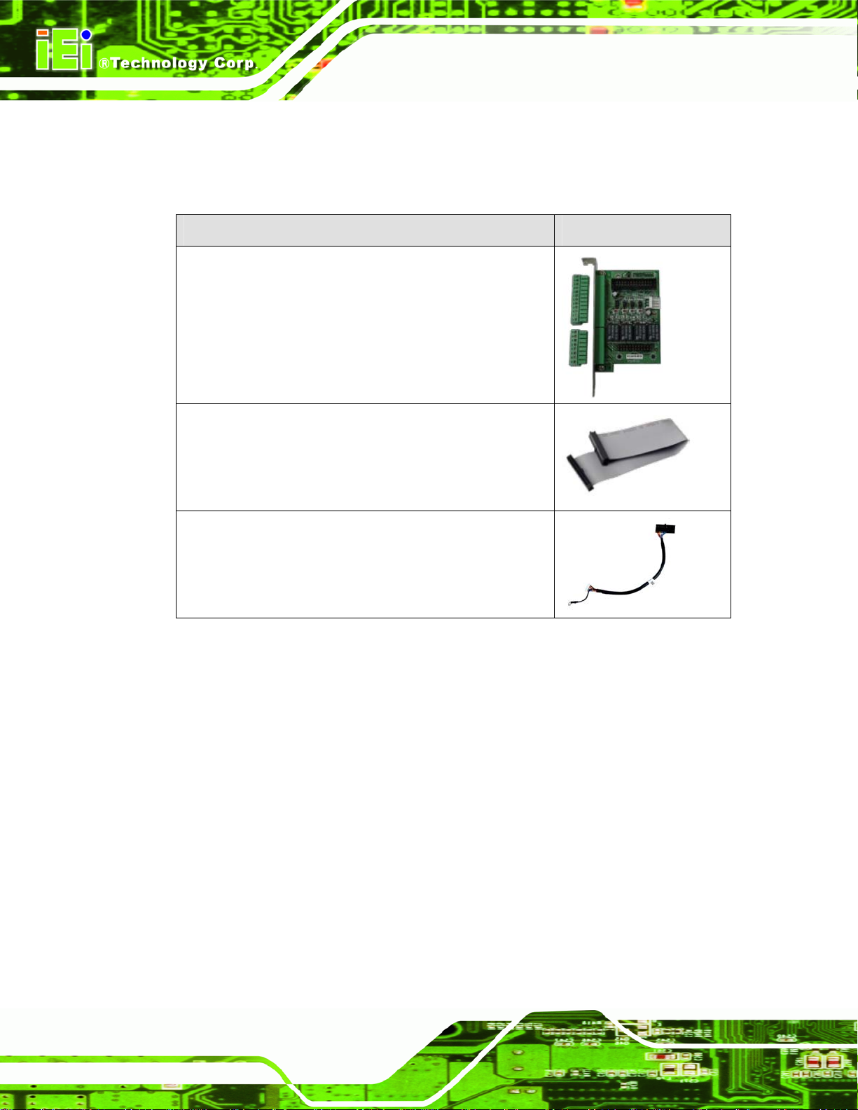
3.4 Optional Items
The following items are optional:
Item and Part Number Image
8-channel GPIO card (four digital output and four relay
output)
(P/N: VIOCARD-GPIO-RS-R10)
GPIO cable (for IVCE-C608 and IVCE-C604)
(P/N: 32200-000012-RS)
IVCE-C608/IVCE-C604/IVCME-C604 Capture Card
GPIO cable (for IVCME-C604)
(P/N: 32031-000100-100-RS)
Table 3-2: Optional Items
Page 28
Page 29

IVCE-C608/IVCE-C604/IVCME-C604 Capture Card
Chapter
4
4 Connectors and
Jumpers
Page 29
Page 30

IVCE-C608/IVCE-C604/IVCME-C604 Capture Card
4.1 Video Capture Card Connector Diagrams
The connector diagrams for both models are shown in the sections below:
4.1.1 IVCE-C608 Pinouts
WARNING:
The other connectors, jumpers and interfaces on the board not
specified below are for R&D diagnostic purposes and should not be
used by the end user.
The IVCE-C608 has the following connectors and interfaces on board:
Quantity Connector Name Connector Ty pe Labels
1 Rotary Switch (ID Selection) 16-position switch SW1
1 LED screen LED screen LED2
1 LED indicators Red, amber, green LED LED1
2 GPIO connector 26-pin box header CN2, CN3
1 Video/Audio input/output
connector
1 Reset input connector 2-pin header CN4
1 Reset output connector 2-pin header CN5
DB-26 female J1
Table 4-1: IVCE-C608 Connectors
Figure 4-1 shows the connectors, jumpers and interfaces on the IVCE-C608.
Page 2
Page 31
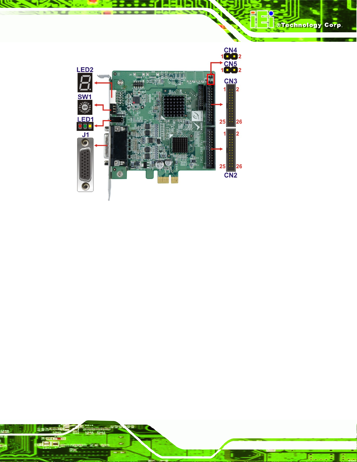
IVCE-C608/IVCE-C604/IVCME-C604 Capture Card
Figure 4-1: IVCE-C608 Connectors and Pinouts (pin numbers in red)
4.1.1.1 IVCE-C608 Switch (SW1)
Use the 16-position rotary switch (SW1) to set the ID for the board. Up to 16 IVCE-C608
can be installed in a single system. Each card must be allocated a unique ID. Switch ID
settings are explained in more detail in Section
5.4.5.
4.1.1.2 IVCE-C608 LED Screen (LED2)
The LED screen shows the ID number of the IVCE-C608. Sixteen IVCE-C608 cards can
be connected together in a singles system. Each card has a unique ID setting as specified
by the unique rotary switch (SW1) setting described above and in Section
unique card ID specified by the rotary switch (SW1) is specified on the screen.
5.4.5. The
4.1.1.3 IVCE-C608 LED Indicators (LED1)
The LED indicator (LED1) includes three LED indicators: Amber, green and red. These
LED indicators show the system status as described below:
Amber: watchdog alarm
Page 3
Page 32

IVCE-C608/IVCE-C604/IVCME-C604 Capture Card
Green: self-defined
Red: self-defined
4.1.1.4 IVCE-C608 Reset Input Connector (CN4)
Use the reset input connector (CN4) to connect to the reset button of the system chassis
to enable the multiple card cascade reset function. Pinouts for the connector are shown in
Table 4-2.
Pin No. Signal
1 Reset input
2 GND
Table 4-2: IVCE-C608 Reset Input Connector Pinouts
4.1.1.5 IVCE-C608 Reset Output Connector (CN5)
Use the reset output connector (CN5) to connect to the reset connector on the
motherboard to enable the multiple card cascade reset function. Pinouts for the connector
are shown in
Pin No. Signal
1 Reset output
2 GND
Table 4-3.
Table 4-3: IVCE-C608 Reset Output Connector Pinouts
4.1.1.6 IVCE-C608 Video/Audio Input/Output Connector (J1)
Compatible cameras connect to the IVCE-C608 through the DB-26 female connector (via
the D-SUB to BNC and RCA cable). Pinouts for the connector are shown in
Pin No. Signal Pin No. Signal
1 Video In CH1 2 Video In CH2
3 Video In CH3 4 Video In CH4
Table 4-4.
Page 4
5 Video In CH5 6 Video In CH6
7 Video In CH7 8 Video In CH8
9 Video Output 1 10 NC
Page 33

IVCE-C608/IVCE-C604/IVCME-C604 Capture Card
11 GND 12 GND
13 GND 14 GND
15 GND 16 GND
17 GND 18 Video Output 2
19 Audio In CH1 20 Audio In CH2
21 Audio In CH3 22 Audio In CH4
23 Audio In CH5 24 Audio In CH6
25 Audio In CH7 26 Audio In CH8
Table 4-4: IVCE-C608 Video/Audio Input Connector Pinouts
Each IVCE-C608 can support up to eight video inputs, eight audio inputs and two video
outputs . If 16 systems are connected together, a total of 128 cameras can be strung
together in a single system.
4.1.1.7 IVCE-C608 GPIO Connector (CN2, CN3)
The IVCE-C608 contains two 26-pin box header GPIO connectors. The GPIO connector
pinouts are shown in
Pin No. Signal Pin No. Signal
1 NC 2 NC
3 NC 4 NC
5 NC 6 NC
7 NC 8 NC
9 NC 10 GND
11 DO0 12 GND
13 DO1 14 GND
15 DO2 16 GND
17 DO3 18 GND
19 DI0 20 GND
21 DI1 22 GND
Table 4-5.
23 DI2 24 GND
25 DI3 26 NC
Table 4-5: IVCE-C608 GPIO Connector Pinouts
Page 5
Page 34

4.1.2 IVCE-C604 Pinouts
WARNING:
The other connectors, jumpers and interfaces on the board not
specified below are for R&D diagnostic purposes and should not be
used by the end user.
The IVCE-C604 has the following connectors and interfaces on board:
Quantity Connector Name Connector Type Labels
1 Rotary Switch (ID Selection) 16-position switch SW1
1 LED screen LED screen LED2
IVCE-C608/IVCE-C604/IVCME-C604 Capture Card
1 LED indicators Red, amber, green LED LED1
1 GPIO connectors 26-pin box header CN3
1 Video/Audio input/output
connector
1 Reset input connector 2-pin header CN4
1 Reset output connector 2-pin header CN5
DB-26 female J1
Table 4-6: IVCE-C604 Connectors
Figure 4-2 shows the connectors and interfaces on the IVCE-C604.
Page 6
Page 35

IVCE-C608/IVCE-C604/IVCME-C604 Capture Card
Figure 4-2: IVCE-C604 Connectors and Pinouts (pin numbers in red)
4.1.2.1 IVCE-C604 Switch (SW1)
Use the 16-position rotary switch (SW1) to set the ID for the board. Up to 16 IVCE-C604
can be installed in a single system. Each card must be allocated a unique ID. Switch ID
settings are explained in more detail in Section
5.4.5.
4.1.2.2 IVCE-C604 LED Screen (LED2)
The LED screen shows the ID number of the IVCE-C604. Sixteen IVCE-C604 cards can
be connected together in a singles system. Each card has a unique ID setting as specified
by the unique rotary switch (SW1) setting described above and in Section
unique card ID specified by the rotary switch (SW1) is specified on the screen.
5.4.5. The
4.1.2.3 IVCE-C604 LED Indicators (LED1)
The LED indicator (LED1) includes three LED indicators: amber, green and red. These
LED indicators show the system status as described below:
Amber: watchdog timer alarm
Page 7
Page 36

IVCE-C608/IVCE-C604/IVCME-C604 Capture Card
Green: self-defined
Red: self-defined
4.1.2.4 IVCE-C604 Reset Input Connector (CN4)
Use the reset input connector (CN4) to connect to the reset button of the system chassis
to enable the multiple card cascade reset function. Pinouts for the connector are shown in
Table 4-7.
Pin No. Signal
1 Reset input
2 GND
Table 4-7: IVCE-C604 Reset Input Connector Pinouts
4.1.2.5 IVCE-C604 Reset Output Connector (CN5)
Use the reset output connector (CN5) to connect to the reset connector on the
motherboard to enable the multiple card cascade reset function. Pinouts for the connector
are shown in
Pin No. Signal
1 Reset output
2 GND
Table 4-8.
Table 4-8: IVCE-C604 Reset Output Connector Pinouts
4.1.2.6 IVCE-C604 Video/Audio Input/Output Connector (J1)
Compatible cameras connect to the IVCE-C604 through the DB-26 female connector (via
the D-SUB to BNC and RCA cable). Pinouts for the connector are shown in
Pin No. Signal Pin No. Signal
1 Video In CH1 2 Video In CH2
3 Video In CH3 4 Video In CH4
Table 4-9.
Page 8
5 NC 6 NC
7 NC 8 NC
9 Video Output 1 10 NC
Page 37

IVCE-C608/IVCE-C604/IVCME-C604 Capture Card
11 GND 12 GND
13 GND 14 GND
15 GND 16 GND
17 GND 18 Video Output 2
19 Audio In CH1 20 Audio In CH2
21 Audio In CH3 22 Audio In CH4
23 NC 24 NC
25 NC 26 NC
Table 4-9: IVCE-C604 Video/Audio Input Connector Pinouts
Each IVCE-C604 can support up to four video inputs, four audio inputs and two video
outputs . If 16 systems are connected together, a total of 64 cameras can be stru ng
together in a single system.
4.1.2.7 IVCE-C604 GPIO Connector (CN3)
The IVCE-C604 contains one 26-pin box header GPIO connector. The GPIO connector
pinouts are shown in
Pin No. Signal Pin No. Signal
1 NC 2 NC
3 NC 4 NC
5 NC 6 NC
7 NC 8 NC
9 NC 10 GND
11 DO0 12 GND
13 DO1 14 GND
15 DO2 16 GND
17 DO3 18 GND
19 DI0 20 GND
21 DI1 22 GND
Table 4-10.
23 DI2 24 GND
25 DI3 26 NC
Table 4-10: IVCE-C604 GPIO Connector Pinouts
Page 9
Page 38

4.1.3 IVCME-C604 Pinouts
WARNING:
The other connectors, jumpers and interfaces on the board not
specified below are for R&D diagnostic purposes and should not be
used by the end user.
The IVCME-C604 has the following connectors and interfaces on board:
Quantity Connector Name Connector Type Labels
1 GPIO connectors 9-pin wafer CN2
IVCE-C608/IVCE-C604/IVCME-C604 Capture Card
1 Video/Audio input/output
connector
Table 4-11: IVCME-C604 Connectors
Figure 4-2 shows the connectors and interfaces on the IVCME-C604.
10-pin wafer CN1
Page 10
Figure 4-3: IVCME-C604 Connectors and Pinouts (pin numbers in red)
Page 39

IVCE-C608/IVCE-C604/IVCME-C604 Capture Card
4.1.3.1 IVCME-C604 Video/Audio Input Connector (CN1)
Compatible cameras connect to the IVCME-C604 through the 10-pin wafer connector (via
the D-SUB to BNC and RCA cables). Each IVCME-C604 can support up to four video
inputs and four audio inputs. Pinouts for the connector are shown in
Pin No. Signal
1 GND
2 Video In CH1
3 Video In CH2
4 Video In CH3
5 Video In CH4
6 Audio In CH1
7 Audio In CH2
8 Audio In CH3
9 Audio In CH4
10 GND
Table 4-12: IVCME-C604 Video/Audio Input Connector Pinouts
4.1.3.2 IVCME-C604 GPIO Connector (CN2)
Table 4-9.
The IVCME-C604 contains one 9-pin wafer GPIO connector. The GPIO connector pinouts
are shown in
Pin No. Signal
1 GND
2 DI1
3 DI2
4 DI3
5 DI4
6 DO1
7 DO2
8 DO3
9 DO4
Table 4-10.
Table 4-13: IVCME-C604 GPIO Connector Pinouts
Page 11
Page 40

IVCE-C608/IVCE-C604/IVCME-C604 Capture Card
Chapter
5
5 Hardware Installation
Page 12
Page 41

IVCE-C608/IVCE-C604/IVCME-C604 Capture Card
5.1 Anti-static Precautions
WARNING:
Failure to take ESD precautions during the installation of the
IVCE-C608/IVCE-C604/IVCME-C604 may result in permanent damage
to the IVCE-C608/IVCE-C604/IVCME-C604 and severe injury to the
user.
Electrostatic discharge (ESD) can cause serious damage to electronic components,
including the IVCE-C608/IVCE-C604/IVCME-C604. Dry climates are especially
susceptible to ESD. It is therefore critical that whenever the
IVCE-C608/IVCE-C604/IVCME-C604, or any other electrical component is handled, the
following anti-static precautions are strictly adhered to.
Wear an anti-static wristband: Wearing a simple an ti-static wristband can
help to prevent ESD from damaging the board.
Self-grounding: Before handling the board, touch any grounded conducting
material. During the time the board is handled, frequently touch any
conducting materials that are connected to the ground.
Use an anti-static pad: When configuring the
IVCE-C608/IVCE-C604/IVCME-C604, place it on an antic-static pad. This
reduces the possibility of ESD damaging the
IVCE-C608/IVCE-C604/IVCME-C604.
Only handle the edges of the PCB: When handling the PCB, hold the PCB
by the edges.
Page 13
Page 42

IVCE-C608/IVCE-C604/IVCME-C604 Capture Card
5.2 Installation Considerations
NOTE:
The following installation notices and installation considerations should
be read and understood before installation. All installation notices must
be strictly adhered to. Failing to adhere to these precautions may lead
to severe damage and injury to the person performing the installation.
WARNING:
The installation instructions described in this manual should be
carefully followed in order to prevent damage to the components and
injury to the user.
Before and during the installation please DO the following:
Read the user manual:
o The user manual provides a complete description of the
IVCE-C608/IVCE-C604/IVCME-C604 installation instructions and
configuration options.
Wear an electrostatic discharge cuff (ESD):
o Electronic components are easily damaged by ESD. Wearing an ESD cuff
removes ESD from the body and helps prevent ESD damage.
Place the IVCE-C608/IVCE-C604/IVCME-C604 on an antistatic pad:
o When installing or configuring the motherboard, place it on an antistatic
pad. This helps to prevent potential ESD damage.
Turn all power to the IVCE-C608/IVCE-C604/IVCME-C604 off:
Page 14
o When working with the IVCE-C608/IVCE-C604/IVCME-C604, make sure
that it is disconnected from all power supplies and that no electricity is
being fed into the system.
Before and during the installation of the IVCE-C608/IVCE-C604/IVCME-C604 DO NOT:
Page 43

IVCE-C608/IVCE-C604/IVCME-C604 Capture Card
Remove any of the stickers on the PCB board. These stickers are required for
warranty validation.
Use the product before verifying all the cables and power connectors are
properly connected.
Allow screws to come in contact with the PCB circuit, connector pins, or its
components.
5.3 System Requirement
Microsoft Windows XP
Microsoft Windows 7
Microsoft DirectX 9.0c
5.4 IVCE-C608/IVCE-C604 Hardware Installation
5.4.1 Hardware Installation Procedures
To install the video capture card hardware, the following steps must be followed:
Step 1: Install the video capture card.
Step 2: Install the reset cables (optional).
Step 3: Install the GPIO card (optional).
Step 4: Set the rotary switch ID settings.
Step 5: Connect the video and audio devices.Step 0:
Once the steps above have been completed, the hardware installation procedures are
complete.
5.4.2 Video Capture Card Installation
The IVCE-C608 and IVCE-C604 have a PCIe x1 interface. To install the IVCE-C608 and
IVCE-C604IVCE-C608/IVCE-C604/IVCME-C604, please follow the steps below:
Step 1: Align the PCIe edge connector on the bottom of the video capture card with the
PCIe slot on the system motherboard or a backplane.
Page 15
Page 44
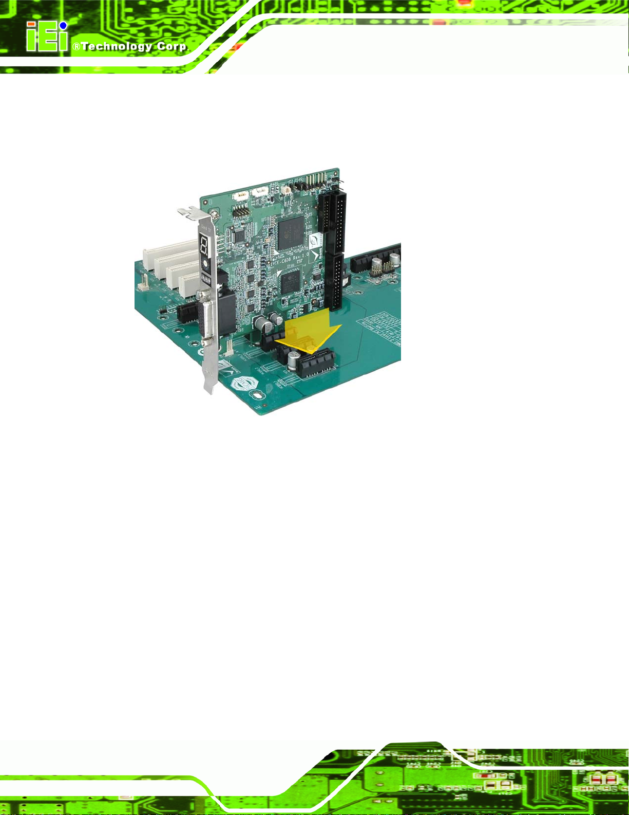
Step 2: Gently insert the video capture card into the PCIe slot.
Step 3: Push down gently on the video card to make sure it is firmly inserted into the
PCIe slot.
IVCE-C608/IVCE-C604/IVCME-C604 Capture Card
Figure 5-1: IVCE-C608 and IVCE-C604 Installation
Step 4: Insert a retention screw through the top of the video capture card external
bracket into the chassis to secure t he card to the chassis. Step 0:
5.4.3 Install the Reset Cables (Optional)
The IVCE-C608 and IVCE-C604 are shipped with two reset cables to support cascade
reset. To install the reset cables, please follow the instructions below.
Step 1: Locate the reset input connector on the first video capture card.
Step 2: Connect the reset button from the chassis to the reset input connector on the
first video card.
Step 3: Use a reset cable to connect the reset output connector on the first video card to
the reset input connector on the second video card.
Page 16
Page 45

IVCE-C608/IVCE-C604/IVCME-C604 Capture Card
Step 4: Repeat Step 3 to connect multiple video capture cards in a system. Up to 16
cards can be added in a system.
Step 5: Use a reset cable to connect the reset output connector on the last video card to
the reset connector on the system motherboard. Step 0:
Figure 5-2: Cascade Reset Connection
5.4.4 Install the GPIO Card (Optional)
The IVCE-C608 and IVCE-C604 support 8-bit GPIO (4-bit input and 4-bit output) via an
optional GPIO card. To install the GPIO card, please follow the instructions below.
Step 1: Locate the GPIO connector on the video capture card (see Section
Step 2: Align the cable connector from the GPIO cable with the GPIO connector on the
video capture card.
1.2).
Page 17
Page 46

Figure 5-3: GPIO Cable for IVCE-C608 and IVCE-C604
Step 3: Push the cable connector onto the video capture card GPIO connector making
sure the pins are correctly aligned.
Step 4: Next, connect the GPIO cable connector to the GPIO connector on the GPIO
card (CN6).Step 0:
IVCE-C608/IVCE-C604/IVCME-C604 Capture Card
5.4.4.1 GPIO Card Pinouts
The following diagram shows the pinouts of the two terminal blocks of the optional GPIO
card.
Page 18
Figure 5-4: GPIO Card Pinouts
Page 47

IVCE-C608/IVCE-C604/IVCME-C604 Capture Card
5.4.5 Set the Rotary Switch ID Settings
Up to 16 IVC video cards can be installed simultaneously on a single system. However, to
ensure the system is able to detect the different cards, each card must be assigned a
unique ID. The unique ID is assigned using the 16-position rotary switch (0~F) on each
IVC video card. The ID number of the video card will show on the LED screen.
Figure 5-5: LED Screen and ID Rotary Switch
NOTE:
1. If the card ID shown on the application is different from the number
shown on the LED screen, please restart the system.
2. DO NOT change the card ID during operation.
Page 19
Page 48

IVCE-C608/IVCE-C604/IVCME-C604 Capture Card
5.4.6 Video and Audio Input Connection
Both IVCE-C608 and IVCE-C604 are shipped with a video and audio input cable. To
install the video and audio input cable, please follow the instructions below.
NOTE:
The IVCE-C608 is shipped with an 8-channel video and 8-channel
audio input cable whereas the IVCE-C604 is shipped with a 4-channel
video and 4-channel audio input cable.
Figure 5-6: Video and Audio Input Connection
Step 1: Align and insert the DB-26 male connector from the cable to the DB-26 female
connector on the board.
Step 2: Make sure the connection is secure.
Page 20
Page 49

IVCE-C608/IVCE-C604/IVCME-C604 Capture Card
Step 3: Connect the video input BNC connector (black) from the cable to a video device
with the RG-59 coaxial cable (75 ohms).
Step 4: Connect the audio input RCA connector (white) from the cable to an audio
device.
Step 5: Repeat Step 3 and Step 4 until all video and audio devices are connected.
Step 0:
NOTE:
Up to eight video devices and eight audio devices can be connected to
the IVCE-C608 video capture card.
Up to four video devices and four audio devices can be connected to
the IVCE-C604 video capture card.
5.4.7 Video Output Connection
The IVCE-C608 and IVCE-C604 are shipped with a video cable that provides 2-channel
video output. To install the video cable, please follow the instructions below.
Page 21
Page 50

IVCE-C608/IVCE-C604/IVCME-C604 Capture Card
Figure 5-7: Video Output Connection
Step 1: Align and insert the DB-26 male connector from the cable to the DB-26 female
connector on the board.
Step 2: Make sure the connection is secure.
Step 3: Connect the video output BNC connector (yellow) from the cable to a video
device with the BNC cables.
Step 4: Repeat Step 3 to connect the second video output device.Step 0:
5.5 IVCME-C604 Hardware Installation
5.5.1 Hardware Installation Procedures
To install the video capture card hardware, the following steps must be followed:
Step 1: Install the video capture card.
Page 22
Step 2: Install the GPIO card (optional).
Step 3: Connect the video and audio devices.Step 0:
Once the steps above have been completed, the hardware installation procedures are
complete.
Page 51

IVCE-C608/IVCE-C604/IVCME-C604 Capture Card
5.5.2 Video Capture Card Installation
To install the IVCME-C604, please refer to the diagram and instructions below.
Figure 5-8: IVCME-C604 Installation
Step 1: Insert into the socket at an angle. Line up the notch on the card with the notch
on the connector. Slide the IVCME-C604 into the socket at an angle of about
20º.
Step 2: Push down until the card clips into place. Push the other end of the card
down until it clips into place on the plastic connector.Step 0:
5.5.3 Video and Audio Input Connection
The IVCME-C604 is shipped with a video/audio input cable, a 4-channel video input cable
and a 4-channel audio input cable. To install the video and audio input cable, pl ease follow
the instructions below.
Page 23
Page 52
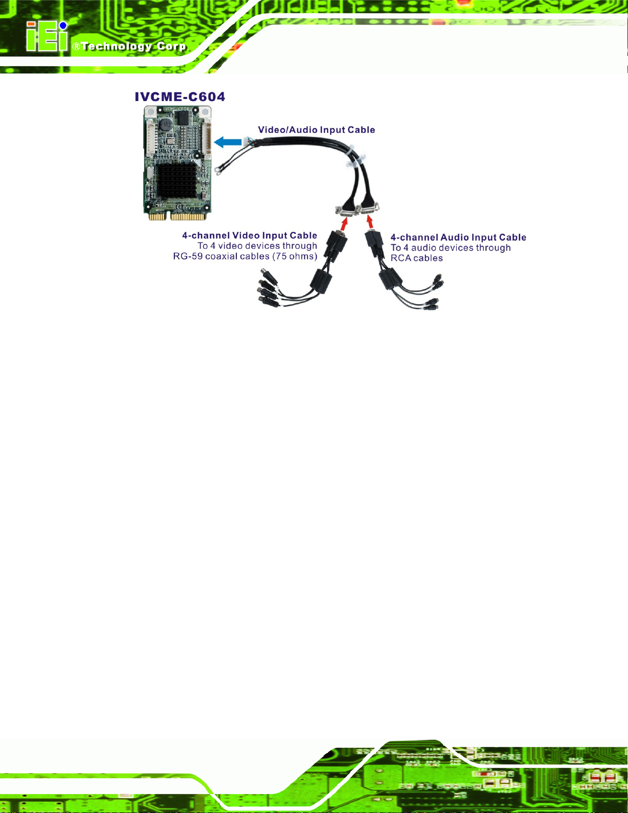
IVCE-C608/IVCE-C604/IVCME-C604 Capture Card
Figure 5-9: Video and Audio Input Connection (IVCME-C604)
Step 1: Align and insert the wafer connector from the video/audio input cable to the
10-pin wafer connector (CN1) on the board.
Step 2: Make sure the connection is secure.
Step 3: Connect the 4-channel video input cable to the video connector of the
video/audio input cable.
Step 4: Connect the 4-channel audio input cable to the audio connector of the
video/audio input cable.
Step 5: Connect the video input BNC connector (black) from the cable to a video device
with the RG-59 coaxial cable (75 ohms).
Step 6: Connect the audio input RCA connector (white) from the cable to an audio
device.
Page 24
Step 7: Repeat Step 5 and Step 6 until all video and audio devices are connected.
Step 0:
Page 53

IVCE-C608/IVCE-C604/IVCME-C604 Capture Card
5.5.4 Install the GPIO Card (Optional)
The IVCME-C604 supports 8-bit GPIO (4-bit input and 4-bit output) via an optional GPIO
card. To install the GPIO card, please follow the instructions below.
Step 1: Locate the GPIO connector on the IVCME-C604 video capture card (see
Section
Step 2: Align the cable connector from the GPIO cable with the GPIO connector on the
video capture card.
Figure 5-10: GPIO Cable for IVCME-C604
Step 3: Push the cable connector onto the video capture card GPIO connector making
sure the pins are correctly aligned.
Step 4: Next, connect the GPIO cable connector to GPIO connector on the GPIO card
(CN6). Please refer to Section
1.2.3).
5.4.4.1 for the GPIO card pinouts. Step 0:
Page 25
Page 54

IVCE-C608/IVCE-C604/IVCME-C604 Capture Card
Chapter
6
6 Software and Driver
Page 26
Page 55

IVCE-C608/IVCE-C604/IVCME-C604 Capture Card
6.1 Overview
A CD is shipped with the video capture card. The CD contains a driver for the Conexant
video capture controllers on the card. When the video capture card is installed on the
system, the driver must be installed. Failure to install the driver means the video capture
card cannot be detected by the system.
6.2 Driver and Application Installation
To install the driver and the IEI video capture test suite, please follow the steps below:
Step 1: Insert the disk into a CD disk drive connected to the system. An autorun file
starts. The screen in
Figure 6-1 appears.
Figure 6-1: Autorun Startup Screen
Step 2: Select the model installed on the system from the menu in
Step 3: The screen in
Figure 6-2 appears.
Figure 6-1.
Page 27
Page 56

IVCE-C608/IVCE-C604/IVCME-C604 Capture Card
Figure 6-2: Driver Directory Icon
Step 4: Double click the Driver Demo Application directory icon in
Step 5: The driver folder appears. Choose a driver installation file (.exe) that matches
the capture card model and the system OS. Double click the file to start the
driver installation. For example, to instal l the IVCE-C6 04 driver in a Wind ows XP
system, double click the IVCE-C6XX_Series_32Bit_V1.2.0_20111213.exe icon
in the driver folder.
Figure 6-2.
NOTE:
To be able to install the driver and the IEI Video Capture Test Suite in a 64-bit
operating system (such as Windows 7), please do the followings:
1. Login the system as “administrator” and run “ReallyDisableUAC-Win7.reg”
from the driver CD. Then, restart the system.
2. When the system is booting, press F8 to enter the Advanced Boot Options
Page 28
menu. Choose “Disable Driver Signature Enforcement” and press Enter.
3. Login the system as “administrator” and start to install the driver and
application.
Page 57

IVCE-C608/IVCE-C604/IVCME-C604 Capture Card
Step 6: The screen in Figure 6-3 appears. Select components to install. Cli ck the +
button to expand the card ID option list. Select the video capture card ID to
install the driver. Click the I
installation process.
Figure 6-3: Driver Installation - Select Card ID
NSTALL button in Figure 6-3 to continue the
Step 7: If the following window appears, click Continue Anyway.
Figure 6-4: Windows Warning Window
Page 29
Page 58
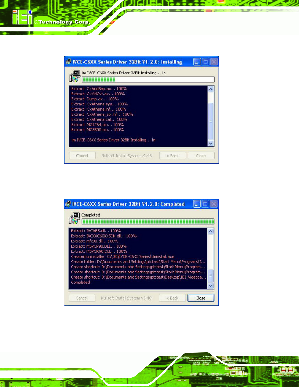
Step 8: The driver starts to install a nd the screen in Figure 6-5 appears.
IVCE-C608/IVCE-C604/IVCME-C604 Capture Card
Figure 6-5: Driver Installing
Step 9: When the driver installation is complete, the screen in
Figure 6-6 appears.
Page 30
Figure 6-6: Driver Installation Complete
Step 10: Click C
Step 11: Check the device manager in the Windows control panel to ensure the drivers
LOSE to finish. Restart the computer.
Page 59

IVCE-C608/IVCE-C604/IVCME-C604 Capture Card
have been properly installed (Figure 6-7).
Figure 6-7: Device Manager
Step 12: The IEI Video Capture Test Suite shortcut is shown on the desktop (
The test suite can also be accessed from the following directory:
C:\IEI\IVCE-C6XX Series.
Figure 6-8).
Figure 6-8: IEI Video Capture Test Suite Shortcut Icon
6.2.1 FFDShow Installation
Step 1: Download the FFDShow video encoder from the Internet. Install the FF DShow in
the system.
Page 31
Page 60

Step 2: Launch the “FFDShow video encoder configuration” from the start menu. Start
menu Æ ffdshow Æ VFW configuration.
IVCE-C608/IVCE-C604/IVCME-C604 Capture Card
Figure 6-9: FFDShow - VFW Configuration
Step 3: The ffdshow video encoder configuration window appears. Select MJPEG
encoder.
Page 32
Figure 6-10: FFDShow Video Encoder Configuration Window
Page 61

IVCE-C608/IVCE-C604/IVCME-C604 Capture Card
6.2.2 Uninstall Driver and Application
Step 1: To uninstall the test suite, select Uninstall in the “IVCE-C6XX Series” folder
from the start-up menu (
Figure 6-11: Uninstall IEI Video Capture Test Suite (Start Menu)
Figure 6-11).
Step 2: To uninstall the driver, right click the video capture card and select Uninstall in
the Device Manager window as shown in
Figure 6-11.
Page 33
Page 62
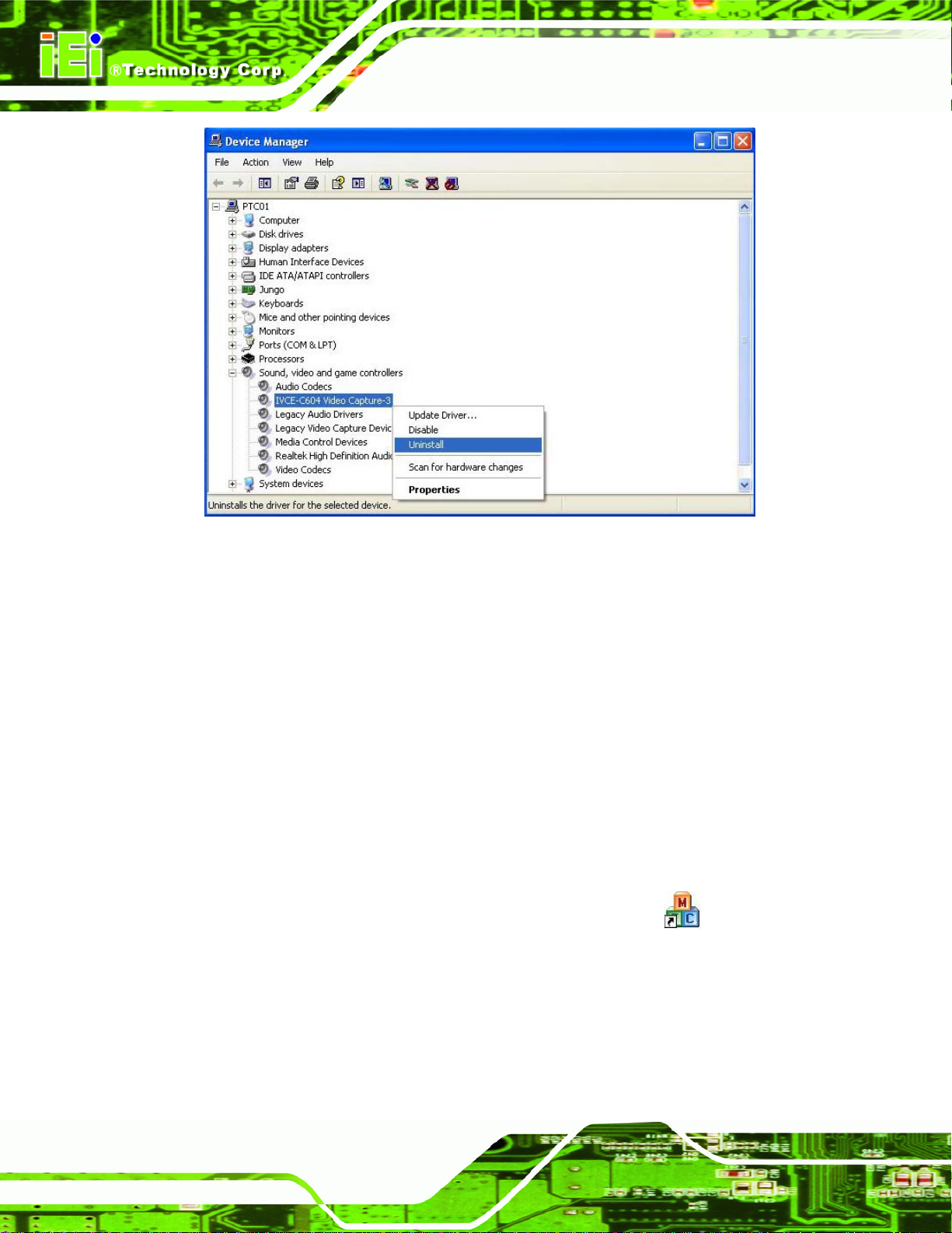
Figure 6-12: Device Manager – Uninstall Driver
IVCE-C608/IVCE-C604/IVCME-C604 Capture Card
6.3 IEI Video Capture Test Suite
The IEI Video Capture Test Suite is a demonstration application for the
IVCE-C608/IVCE-C604/IVCME-C604 video capture card. Before using the IEI Video
Capture Test Suite, please complete the hardware installation and the software
installation described in the previous sections.
6.3.1 Video Capture
To use the IEI Video Capture Test Suite to capture video, follow the steps below.
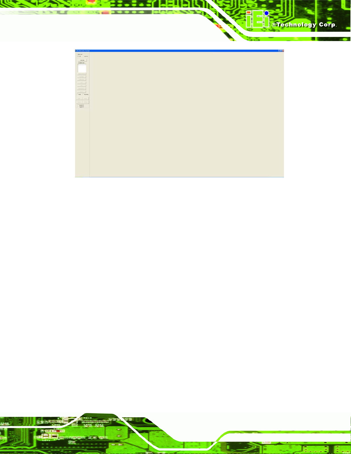
Step 1: Launch the Test Suite by double clicking the desktop icon
Figure 6-13 appears. The setting buttons are on the left side panel of the
interface.
. The window in
Page 34
Page 63
IVCE-C608/IVCE-C604/IVCME-C604 Capture Card
Figure 6-13: IEI Video Capture Test Suite
Step 2: Select the capture card type: PCIE or MiniPCIE.
Step 3: Click the Get Cards button. The capture cards connected to the system shows.
Select one capture card from the list. The card number is corresponding to the
card ID shown on the card, which is selected by the rotary switch.
Step 4: Configure the capture settings by clicking the Capture Settings button.
Page 35
Page 64

Figure 6-14: Available Cards
IVCE-C608/IVCE-C604/IVCME-C604 Capture Card
Step 5: The Capture Settings window appears.
Page 36
Figure 6-15: Capture Settings Window
Page 65

IVCE-C608/IVCE-C604/IVCME-C604 Capture Card
Step 6: Select a video standard (NTSC or PAL) and video resolutions. The supported
resolutions of the two video standards are listed below.
NTSC PAL
720x480
720x240
640x480
640x240
352x240
320x240
160x120
720x576
720x288
352x288
Table 6-1: Supported Resolutions
Step 7: Select camera channel(s) to capture the video from.
NOTE:
If the IVCE-C608 or IVCE-C604 capture card is used, select camera1,
3, 5, 7, 9, 11, 13 or 15 (as shown below).
If the IVCME-C604 capture card is used, select camera1, 2, 3 or 4 (as
shown below).
Page 37
Page 66

Step 8: Select one audio channel (1~8) for preview, which mean the user can hear the
sound from the selected audio channel when capturing video and audio.
However, if the user ch ooses to record the captured video (see Step 11), all of
the connected audio channels will be captured and saved in sep a rate audio file s
(e.g., four audio files will be saved if four audio channels are connected).
IVCE-C608/IVCE-C604/IVCME-C604 Capture Card
Figure 6-16: Audio Preview Selection
NOTE:
The IVCE-C608/IVCE-C604/IVCME-C604 supports mono audio
capture. However, the sound captured by the IVCME-C604 can only be
heard from one speaker.
Step 9: To record and save the captured video (AVI format), choose a file pa th for saving
the files in the Capture Settings window.
Page 38
Page 67

IVCE-C608/IVCE-C604/IVCME-C604 Capture Card
Figure 6-17: Recording File Path Selection
Step 10: Click OK to save settings and exit the Capture Settings window.
Step 11: In the main interface, check the Audio checkbox to capture audio. Check the
Recording checkbox to record the video and save in AVI format
Figure 6-28).
(see
Step 12: Click the RUN button to start capturing videos. Click the STOP button to stop.
Step 13: To capture all channels fro m multiple ca pture ca rd s, click the RUNALL button on
the test suite interface (see
capturing all channels.
Figure 6-18: Start Video Capture
Step 14: The Test Suite starts capturing. Step 0:
Figure 6-28). Click the STOPALL button to stop
Page 39
Page 68

IVCE-C608/IVCE-C604/IVCME-C604 Capture Card
Figure 6-19: Capturing Video
6.3.2 Video Bypass (IVCE-C608 and IVCE-C604 Only)
To view the video input source on another display device in real time, please follow the
steps below.
Step 1: Connect the video input source to the video input port of the IVCE-C608 or the
IVCE-C604.
Step 2: Connect the BNC cable from the display device to the BNC output port of the
IVCE-C608 or the IVCE-C60.
Step 3: Launch the IEI Video Capture Test Suite.
Step 4: Select the capture card type: PCIE or MiniPCIE. Click the Get Cards button.
The capture cards connected to the system shows. Select on e capture card
Page 40
from the list.
Page 69

IVCE-C608/IVCE-C604/IVCME-C604 Capture Card
Step 5: Click the Video Out button:
Step 6: The Video Out window appears.
Figure 6-20: Video Out Window
Step 7: Select which channel to bypass. Once a channel is selected, it will start bypass
the video to the display device. Click the Colour button to adjust the bypass
video. (See
Step 8: Click the Stop button to stop video bypass.
Figure 6-21: Video Out – By pass
Figure 6-21).
Page 41
Page 70

IVCE-C608/IVCE-C604/IVCME-C604 Capture Card
NOTE:
Audio bypass is not available in the current version.
6.3.3 Video Out (IVCE-C608 and IVCE-C604 Only)
The Video Out function allows users to display video (recorded by the test suite) on
display devices through the output ports of the IVCE-C608 or the IVCE-C604. To do this,
follow the steps below.
NOTE:
Please make sure to stop the video by pass before using the video out
function.
Step 1: Connect the video input source to the video input port of the IVCE-C608 or the
IVCE-C604.
Step 2: Connect the BNC cable from the display device to the BNC output port of the
IVCE-C608 or the IVCE-C604.
Step 3: Launch the IEI Video Capture Test Suite.
Step 4: Select the capture card type: PCIE. Click the Get Cards button. The capture
cards connected to the system shows. Select one capture card from the list.
Step 5: Click the Video Out button:
Step 6: The Video Out window appears.
Page 42
Page 71

IVCE-C608/IVCE-C604/IVCME-C604 Capture Card
Step 7: Record a video clip first for video out. Select a standard (NTSC or PAL).
Setup the duration. Specify a path to save the recorded files. Click the Record
button to start recording.
Figure 6-22: Video Out Window (Upper)
WARNING:
To ensure the video quality, it is highly recommended to save the
recorded files in a drive which is not installed with an operating system.
NOTE:
If an issue occurs when recording the video, install a codec pack to
solve the problem, such as the FFDShow video decoder (it is a
freeware).
Step 8: Select a card type – IVCE-C604 or IVCE-C608.
Step 9: Select the video channel 1/2.
Step 10: Click
button to select a video file recorded in Step 7.
Page 43
Page 72

Step 11: Click Run to start displaying the video through the output port.
Figure 6-23: Video Out Window (Bottom)
IVCE-C608/IVCE-C604/IVCME-C604 Capture Card
6.3.4 Other Functions
The IEI Video Capture Test Suite also includes some other functions, including
Frame rate
Color control
GPIO control
Watchdog timer
General information
These functions are described in the following sections.
Page 44
Page 73

IVCE-C608/IVCE-C604/IVCME-C604 Capture Card
6.3.4.1 Frame Rate
The user can view the frame rate when capturing video. Click the Framerate button
to bring up the Frame Rate window. The frame rate of each camera
channel show (refer to
Figure 6-24).
Figure 6-24: Frame Rate Window
Page 45
Page 74
IVCE-C608/IVCE-C604/IVCME-C604 Capture Card
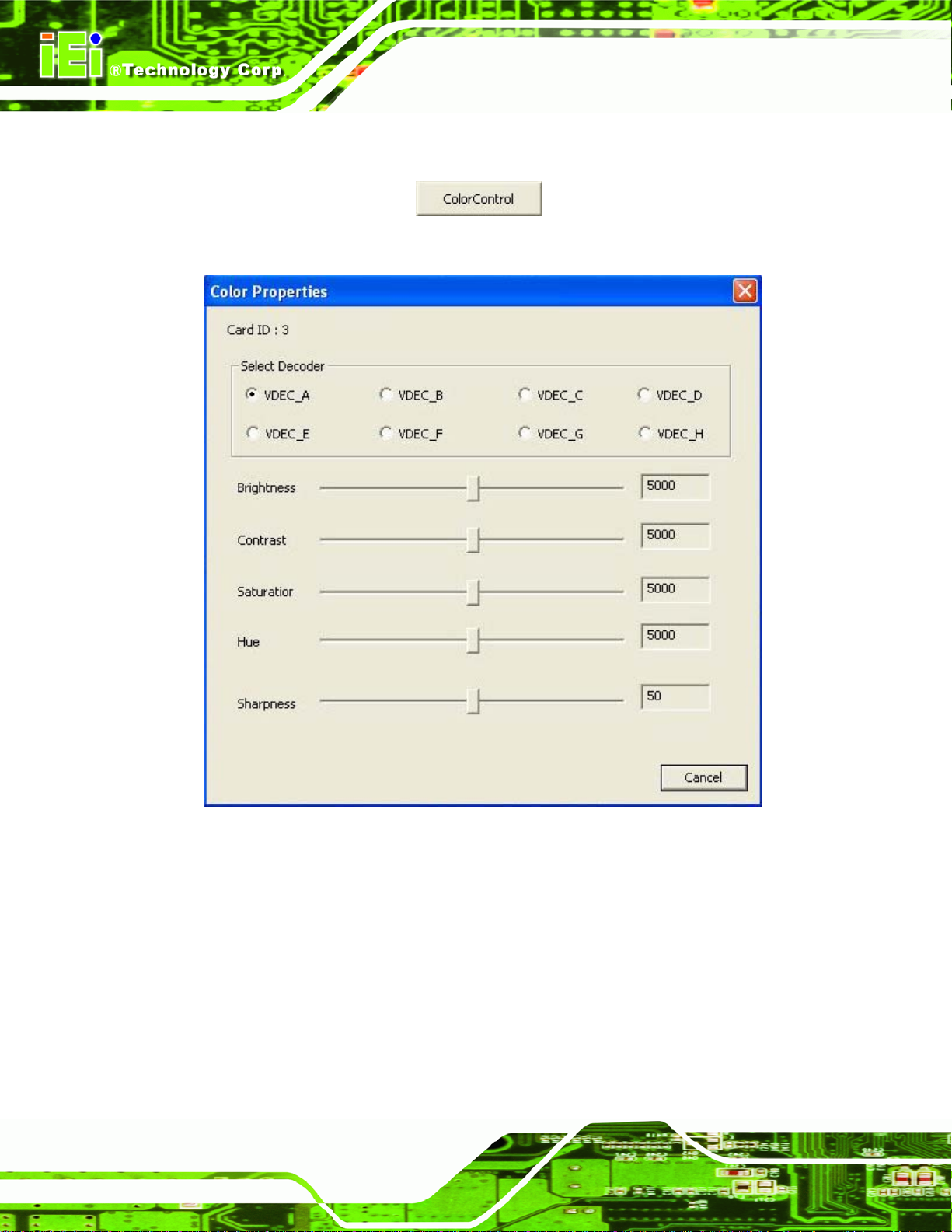
6.3.4.2 Color Control
Click the ColorControl button to bring up the Color Control window
Figure 6-25).
(
Page 46
Figure 6-25: Color Settings
Use the Color Control settings to adjust the image properties of the displayed video of a
single channel. Select the video channel to be adjusted by clicking the correspo nding
channel number (VDEC_A~H). The image properties include brightness, contrast,
saturation, hue and sharpness. Adjust the image properties by dragging the control bar.
Close the window to apply the settings to the selected channel.
Page 75
IVCE-C608/IVCE-C604/IVCME-C604 Capture Card
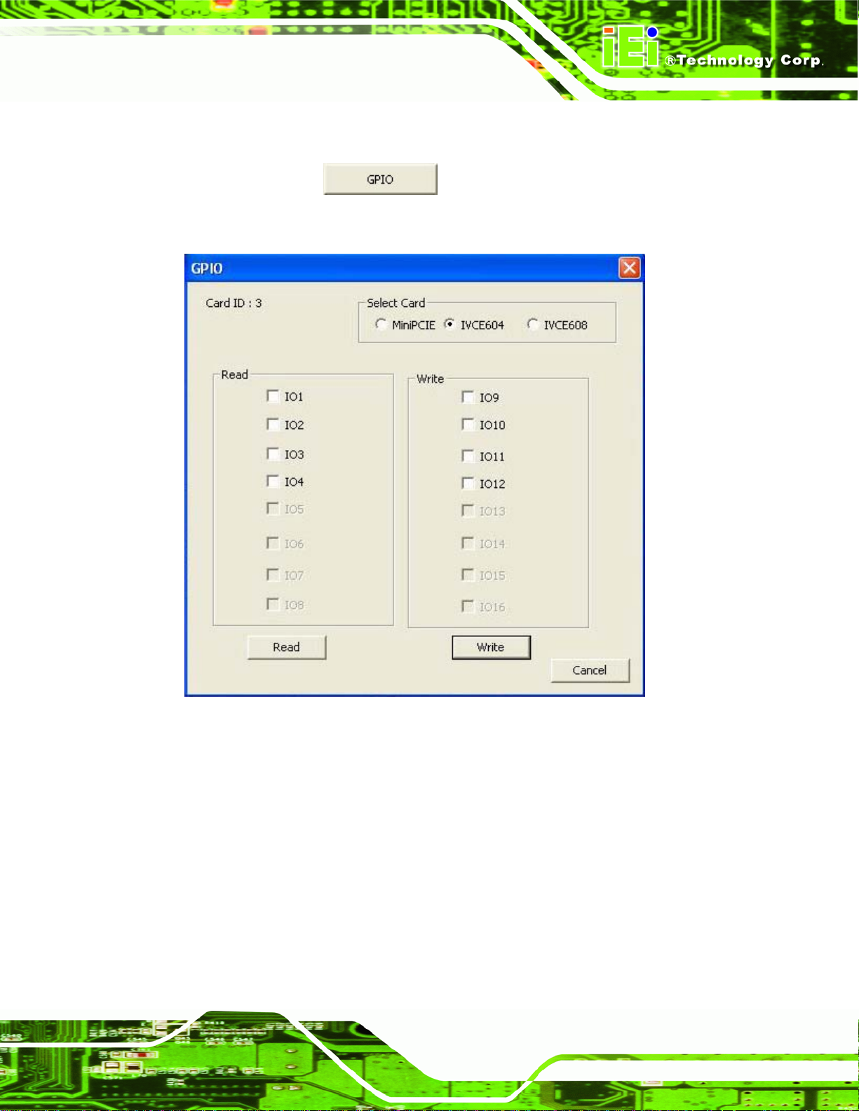
6.3.4.3 GPIO
Click the GPIO button to bring up the GPIO control window (Figure
6-26).
Figure 6-26: GPIO Control
The GPIO function allows users to configure GPIO output signals and read GPIO input
signal if the GPIO connector(s) of the IVCE-C608/IVCE-C604/IVCME-C604 is connected
to an optional GPIO card.
Page 47
Page 76

6.3.4.4 Watchdog Timer (WDT)
To enable watchdog timer, click the WDT button to bring up the WDT
window. Check Enable WDT and/or Toggle WDT options, then click OK. The amber LED
on the capture card lights on indicating that the WDT is enabled.
Figure 6-27: WDT Window
IVCE-C608/IVCE-C604/IVCME-C604 Capture Card
To enable watchdog timer for multiple capture cards, check the checkboxes of the Enable
WDT and/or Toggle WDT options on the test suite main interface (see
Figure 6-28: WDT Options for Multiple Cards
Figure 6-28).
Page 48
Page 77
IVCE-C608/IVCE-C604/IVCME-C604 Capture Card
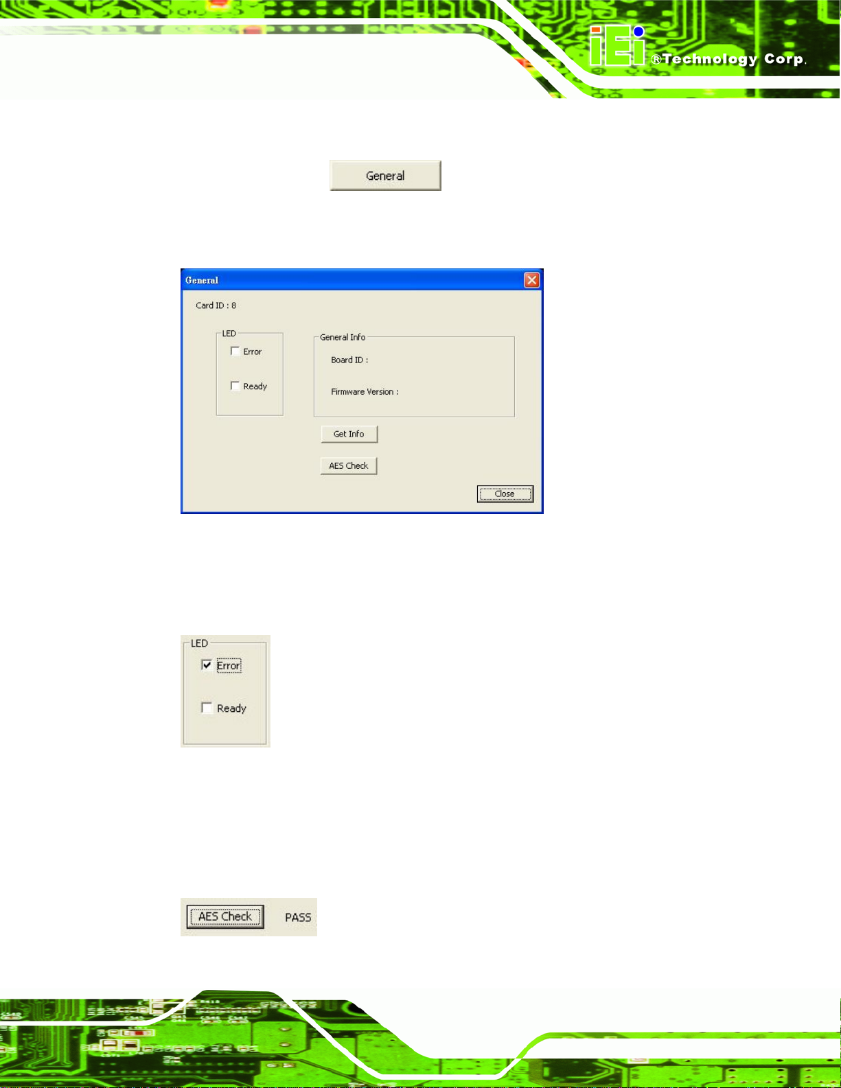
6.3.4.5 General Information
Click the General button to bring up the General window. To view the
general information (board ID and firmware version) of the capture card, click the Ge t Info
button.
Figure 6-29: General Window
To test the LED function on the IVCE-C608 or the IVCE-C604, select the checkbox of the
LEDs. Select Error, the red LED lights on. Select Ready, the green LED lights on.
Figure 6-30: LED Function Test
The IEI Video Capture Test Suite can only be used with IEI
IVCE-C608/IVCE-C604/IVCME-C604 capture cards. Click the AES Check button to check
if the capture card is compatible with the test suite.
Figure 6-31: AES Check - Pass
Page 49
Page 78

IVCE-C608/IVCE-C604/IVCME-C604 Capture Card
Appendix
A
A Hazardous Materials
Disclosure
Page 50
Page 79

IVCE-C608/IVCE-C604/IVCME-C604 Capture Card
A.1 Hazardous Material Disclosure Table for IPB Products Certified as RoHS Compliant Under 2002/95/EC Without Mercury
The details provided in this appendix are to ensure that the product is compliant with the
Peoples Republic of China (China) RoHS standards. The table below acknowledges the
presences of small quantities of certain materials in the product, and is appli cable to China
RoHS only.
A label will be placed on each product to indicate the estimated “Environmentally Friendly
Use Period” (EFUP). This is an estimate of the number of years that these substances
would “not leak out or undergo abrupt change.” This product may contain replaceable
sub-assemblies/components which have a shorter EFUP such as batteries and lamps.
These components will be separately marked.
Please refer to the table on the next page.
Page 51
Page 80

IVCE-C608/IVCE-C604/IVCME-C604 Capture Card
Toxic or Hazardous Substances and Elements Part Name
Lead
(Pb)
Housing
X
Display X
Printed Circuit
X
Mercury
(Hg)
Cadmium
(Cd)
Hexavalent
Chromium
(CR(VI))
Polybrominated
Biphenyls
(PBB)
O O O O
O O O O
O O O O
Polybrominated
Diphenyl Ethers
(PBDE)
X
X
X
Board
Metal
X
O O O O
O
Fasteners
Cable
X
O O O O
X
Assembly
Fan Assembly X
Power Supply
X
O O O O
O O O O
X
X
Assemblies
Battery O
O O O O O
O: This toxic or hazardous substance is contained in all of the homogeneous materials for the pa rt is below
the limit requirement in SJ/T11363-2006
X: This toxic or hazardous substance is contained in at least one of the homogeneous materials for this
part is above the limit requirement in SJ/T11363-2006
Page 52
Page 81

IVCE-C608/IVCE-C604/IVCME-C604 Capture Card
此附件旨在确保本产品符合中国 RoHS 标准。以下表格标示此产品中某有毒物质的含量符
合中国 RoHS 标准规定的限量要求。
本产品上会附有”环境友好使用期限”的标签,此期限是估算这些物质”不会有泄漏或突变”的
年限。本产品可能包含有较短的环境友好使用期限的可替换元件,像是电池或灯管,这些
元件将会单独标示出来。
部件名称
壳体
显示
印刷电路板
金属螺帽
电缆组装
风扇组装
电力供应组装
电池
表示该有毒有害物质在该部件所有物质材料中的含量均在
O:
表示该有毒有害物质至少在该部件的某一均质材料中的含量超出
X:
有毒有害物质或元素
铅
(Pb)
X
X
X
X
X
X
X
O
汞
(Hg)
O O O O
O O O O
O O O O
O O O O
O O O O
O O O O
O O O O
O O O O O
镉
(Cd)
六价铬
(CR(VI))
SJ/T11363-2006
SJ/T11363-2006
多溴联苯
(PBB)
多溴二苯醚
(PBDE)
X
X
X
O
X
X
X
标准规定的限量要求以下。
标准规定的限量要求。
Page 53
 Loading...