

Page 1

IVC-100/100G & IVC-200/200G
& IVC-120/120G & PM-1056
User Manual Version 1.21a
May 09, 2003
©Copyright 2003 by ICP Electronics Inc. All Rights Reserved.
The information in this document is subjected to change without prior notice in
order to improve reliability, design and function and does not represent a
commitment on the part of the manufacturer.
In no event will the manufacturer be liable for direct, indirect, special, incidental, or
consequential damages arising out of the use or inability to use the product or
documentation, even if advised of the possibility of such damages.
This document contains proprietary information protected by copyright. All rights
are reserved. No part of this manual may be reproduced by any mechanical,
electronic, or other means in any form without prior written permission of the
manufacturer.
Trademarks
PM-1056 is a registered trademark of ICP Electronics Inc. IBM PC is a registered
trademark of International Business Machines Corporation. Intel is a registered
trademark of Intel Corporation. Other product names mentioned herein are used
for identification purpose only and may be trademarks and/or registered
trademarks of their respective companies.
1
Page 2

Table of Contents
1. Product Introduction ...................................................... 3
1.1 Common Features for IVC-100G/IVC-100 .......................................3
1.2 Common Features for IVC-200G/IVC-200 .......................................3
1.3 Common Features for IVC-120G/IVC-120 .......................................4
1.4 Special Features for IVC-100G/IVC-200G/IVC120G ..........................4
1.5 Package Contents........................................................................4
1.6 System Requirements ..................................................................4
1.7 Notes ........................................................................................5
2. Hardware Connections & Settings.................................. 6
2.1 Illustration for Video Capture Card.................................................6
2.2 Connections to the Video Source ...................................................8
2.3 LED Jumper Settings....................................................................9
2.4 General Purpose Input Output (GPIO) Connections......................... 10
3. Installation Procedures................................................ 15
3.1 Driver Installation ..................................................................... 15
3.2 Check for Installed Driver ........................................................... 18
4. Demo Programs ........................................................... 20
4.1 Video Image Preview for IVC-100G/100........................................ 20
4.2 Video Image Preview for IVC-200G/200........................................ 22
4.3 Video Image Preview for IVC-120G/120........................................ 22
4.4 Recording the Captured Image .................................................... 25
5. Uninstalling the Program ............................................. 27
Appendix A: Watch Dog Function of IVC-200G-WDT........... 28
Appendix B: PM-1056 Hardware Diagrams......................... 30
2
Page 3

1. Product Introduction
Thank you for choosing IEI IVC-100G/100, IVC-200G/200 and IVC-120G/120 &
PM-1056 video capture cards. These cards enable users to capture live video
from video source such as the CCTV camera. These cards are PCI compliant.
IVC-100G/100 and IVC-200G/200 have four video input channels and an LED
indicator. VC-120G/120 has 16 channels and an LED indicator. This unique
LED feature makes IVC-100G/100, IVC-200G/200 and IVC-120G/120 &
PM-1056 ideal candidates for multi-cards surveillance systems. The
patent-pending LED feature provides a solution to system upgrading and
management. With the help of the LED, users can quickly assign an ID number
to the card for identification, which makes onsite maintenance easier and more
efficient. The operation and driver for PM-1056-4P/4PB/4PG/4PGB and
IVC100/100G, and that for PM-1056-16P/16PG and IVC-120/120G, are the
same.
1.1 Common Features for IVC-100G/IVC-100
• Total frame rate up to 30 frames per second
• 4 channels of BNC composite video input
• LED indicator for easy system management
• NTSC/PAL/SECAM auto sensing
• Resolution (NTSC): 720x480, 704x480, 640x480, 352x240,
320x240, 176x112
• Resolution (PAL): 720x576, 704x576, 640x576, 352x288, 176x144
• Provide WDM driver for Windows 98 SE, Windows ME, Windows
2000 and Windows XP
• Provide Demo Programs and SDK for Windows
• Provide Linux driver for Red Hat 7.2, 7.3, 8.0
1.2 Common Features for IVC-200G/IVC-200
• Total frame rate up to 120 frames per second
• 4 channels of BNC composite video input
• LED indicator for easy system management
• NTSC/PAL/SECAM auto sensing
• Resolution (NTSC): 720x480, 704x480, 640x480, 352x240,
320x240, 176x112
• Resolution (PAL): 720x576, 704x576, 640x576, 352x288, 176x144
• Provide WDM driver for Windows 98 SE, Windows ME, Windows
3
Page 4

2000 and Windows XP
• Provide Demo Application and SDK for Windows
• Provide Linux driver for Red Hat 7.2, 7.3, 8.0
1.3 Common Features for IVC-120G/IVC-120
• Total frame rate up to 30 frames per second
• 16 channels of BNC composite video input
• LED indicator for easy system management
• NTSC/PAL/SECAM auto sensing
• Resolution (NTSC): 720x480, 704x480, 640x480, 352x240,
320x240, 176x112
• Resolution (PAL): 720x576, 704x576, 640x576, 352x288, 176x144
• Provide WDM driver for Windows 98 SE, Windows ME, Windows
2000 and Windows XP
• Provide Demo Application and SDK for Windows
• One video output channel (direct pass through from one of the 16
video input channels)
1.4 Special Features for IVC-100G/IVC-200G/IVC120G
• General Purpose Input & Output for external control and alarm (4
inputs & 4 outputs)
1.5 Package Contents
• Video capture card x 1
• CD x 1
• Hard copy of user manual x 1
• GPIO module:
GPIO daughter board x 1, flat cable x 1, input connector x 1 and
output connector x 1 (for IVC-100G, IVC-200G and IVC-120G only)
• Video connector cable with 16 video inputs and 1 video output x 1
(for IVC-120G and IVC-120 only)
1.6 System Requirements
• IBM or IBM compatible computer
• Pentium 133 MHz CPU or better processor
• Minimum 16 MB memory
• At least one unoccupied PCI slot and IRQ
• Window Screen setting at 16 bits color or higher
4
Page 5

• OS: Windows 98 SE, Windows ME, Windows 2000 and Windows XP
1.7 Notes
• IVC-100G/100/200G/200/120G/120 will take up a set of IRQ and
I/O Address. Please make sure there is a free set of IRQ and I/O
address for IVC-100 to use. The IRQ of the PCI slot can be
modified from the CMOS setting of the motherboard. Please make
the necessary adjustment according to the user manual for the
motherboard.
• If the system has installed other video capture cards before, please
make sure the previous driver has been removed from the system.
• Microsoft DirectX 8.1 or above. The setup program (ieisetup.exe)
will prompt you to install DirectX 8.1 after the program has
completed the driver installation. Therefore, IEI strongly
recommend you to run ieisetup.exe for driver installation.
• Users of Windows XP do not need to install DirectX 8.1 since
Windows XP includes DirectX 8.1.
• About DirectX 8.1:
DirectX 8.1 is a Microsoft shareware, which will help improve
multimedia experiences on most PCs. This latest version of
DirectX offers updated graphics, faster frame rates and more
immersive audio when running programs rich in multimedia
contents. Since DirectX 8.1 is a system component, it cannot be
uninstalled without uninstalling your OS.
5
Page 6
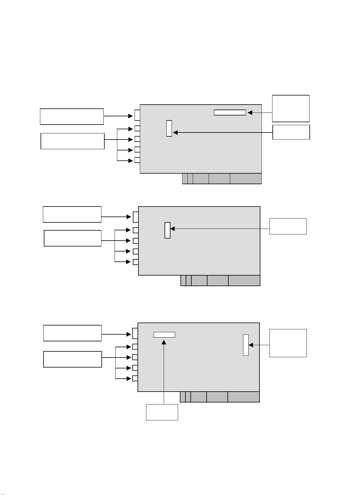
2. Hardware Connections & Settings
2.1 Illustration for Video Capture Card
IVC-100G GPIO = general purpose input output
LED
GPIO pin
connector
BNC connector
Jumper
IVC-100
LED
BNC connector
Jumper
IVC-200G GPIO = general purpose input output
LED
BNC connector
Jumper
GPIO pin
connector
6
Page 7
IVC-200
LED
BNC connector
Jumper
IVC-120G GPIO = general purpose input output
LED
Connector
IVC-120
LED
Connector
GPIO pin
connector
Jumper
Jumper
7
Page 8
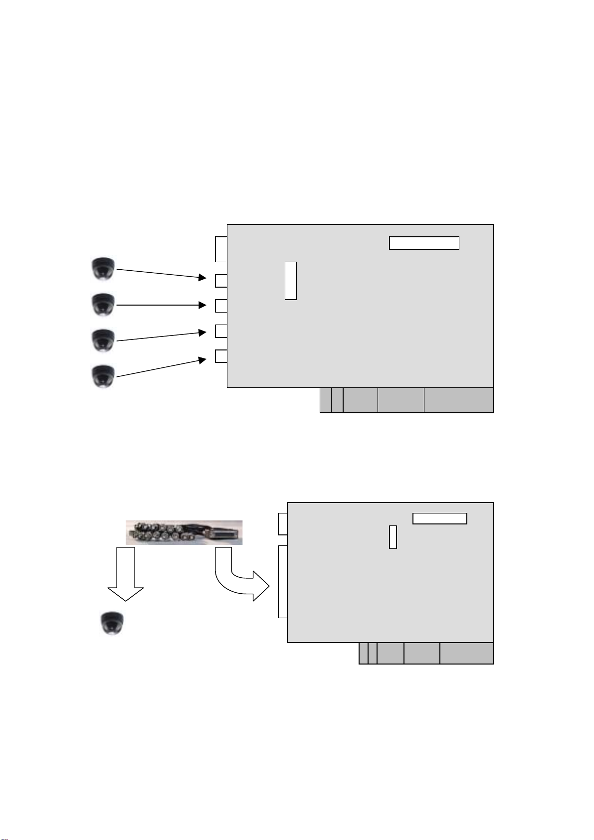
2.2 Connections to the Video Source
Connect your video source to the BNC connector of the video capture card. Take
IVC-100G and IVC-120G for example:
• IVC-100G
Video Source
• IVC-120G
x 16
Video Source
8
Page 9
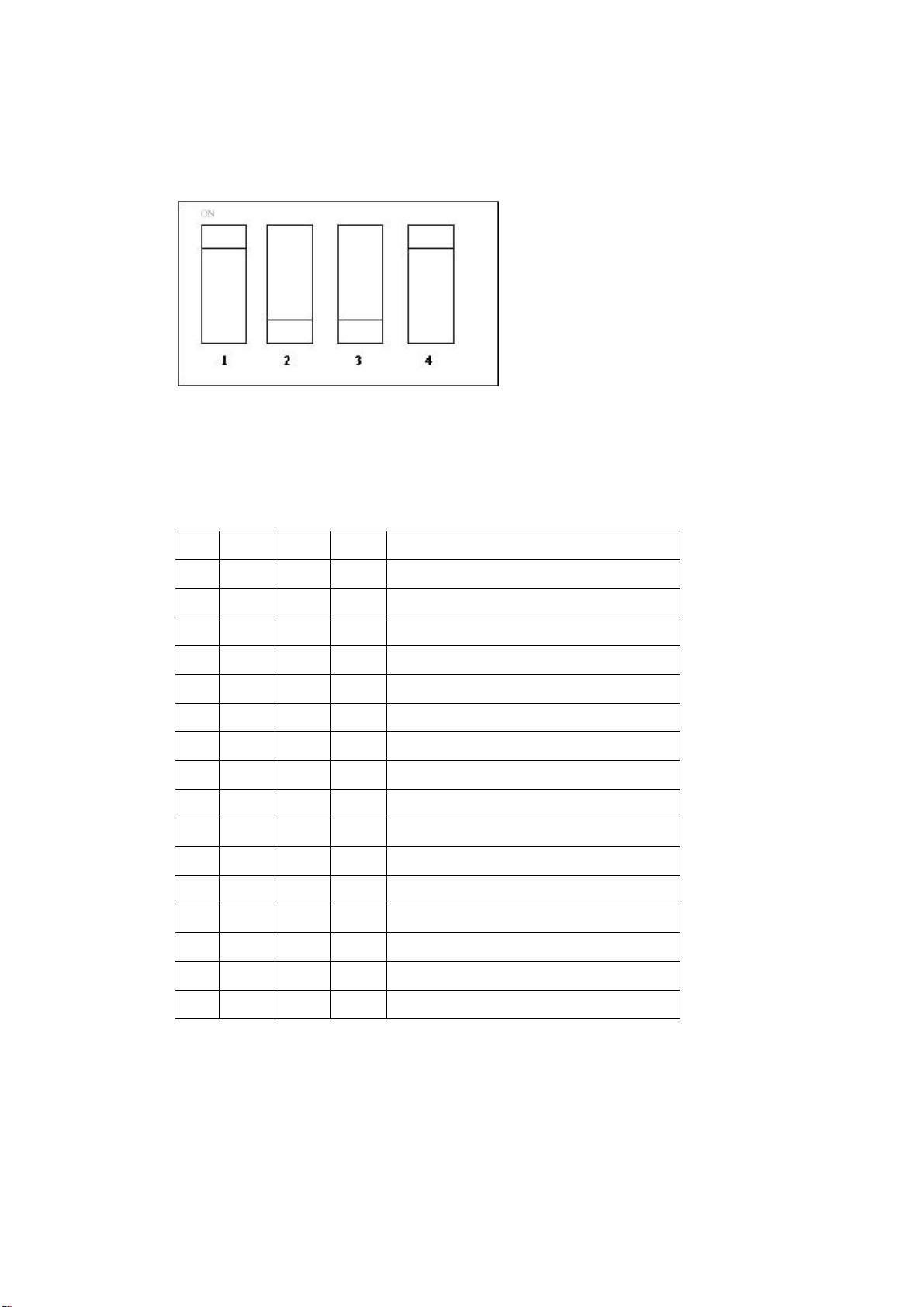
2.3 LED Jumper Settings
The jumper setting controls the card number on the LED.
Jumper Setting Table
Logic 1 = ON Logic 0 = OFF
1 2 3 4 Card Number on the LED
1 1 1 1 0
0 1 1 1 1
1 0 1 1 2
0 0 1 1 3
1 1 0 1 4
0 1 0 1 5
1 0 0 1 6
0 0 0 1 7
1 1 1 0 8
0 1 1 0 9
1 0 1 0 A
0 0 1 0 B
1 1 0 0 C
0 1 0 0 D
1 0 0 0 E
0 0 0 0 F
9
Page 10
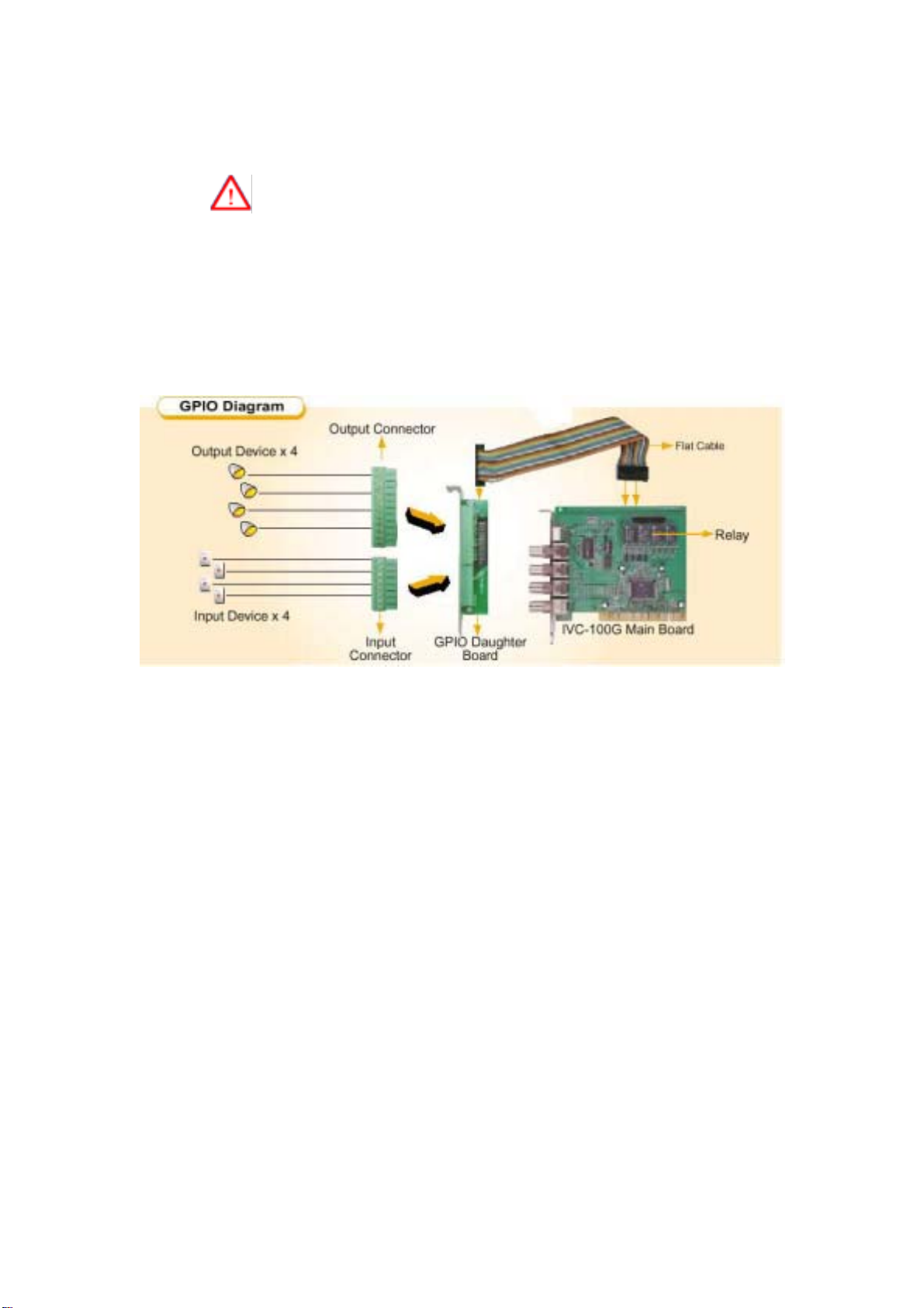
2.4 General Purpose Input Output (GPIO) Connections
Please note that this section ONLY applies to IVC-100G, IVC-200G
and IVC-120G.
The GPIO module contains a flat cable, a GPIO daughter board, an input
connector and an output connector. The GPIO module enables users to
connect four input devices and four output devices.
GPIO module
10
Page 11
Flat cable
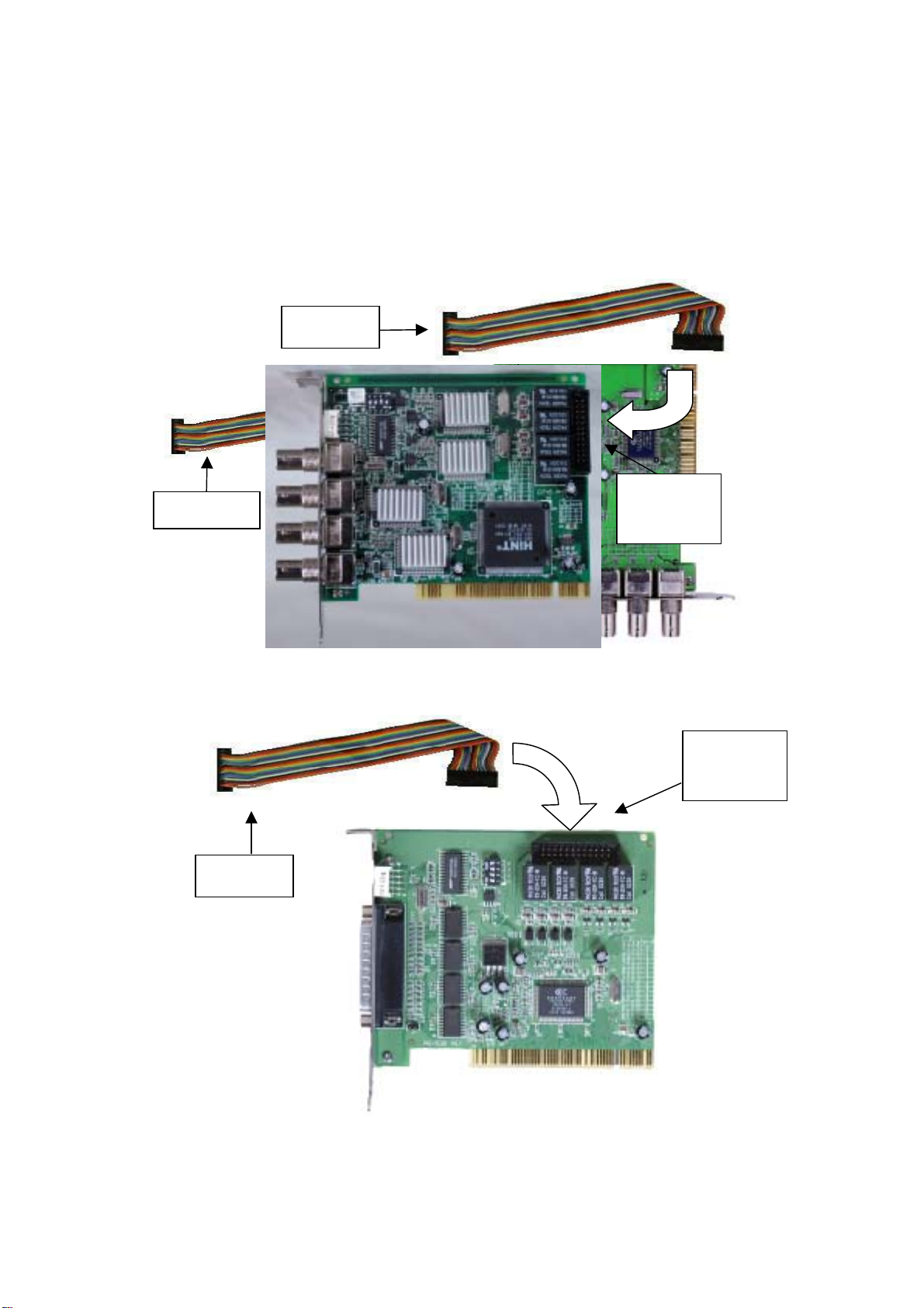
2.4.1 Connections to GPIO daughter board
Connect the flat cable to the GPIO pin connector on IVC-100G
(IVC-200G and IVC-120G).
IVC-200G
Flat cable
GPIO pin connector
GPIO pin
connector
IVC-100G
GPIO pin
connector
Flat cable
IVC-120G
11
Page 12

Connect the other end of the flat cable to the GPIO pin connector on
the GPIO daughter board.
GPIO pin connector
GPIO daughter board
Use the screw to secure the GPIO daughter board on your computer
case.
2.4.2 Connections for Input/Output devices
An input connector and an output connector are provided for
connections to the external devices. The connection points of the
input connector are shown in Figure 1. The connection points of the
output connector are shown in Figure 2.
Input 1
Ground 1
Input 2
Ground 2
Input 3
Ground 3
Input 4
Ground 4
Input Connector
Figure 1
12
Page 13

Common 3
Common 2
Normal Open 2
Normal Close 2
Common 1
Normal Open 1
Normal Close 1
Common 4
Normal Open 4
Normal Close 4
Normal Open 3
Normal Close 3
Figure 2
Output Connector
Specification for General Inputs
The general inputs can take DC voltage from 0-24V. Voltage above 24V is not
recommended.
Logic Voltage Range
0 < 0.5V
1 0.5V – 24V
Specification for General Outputs
Relay Contact Ratings
Contact Form 1 FORM C (SPDT)
Contact Capacity Coil = 0.36W
Resistive Load 1A/125 VAC
(cos θ = 1) 2A/24 VDC
Inductive Load 0.3A/30 VDC
(cos θ = 0.4 L/R = 7 msec)
Rated Carring Current 2A
Max allowable voltage AC 120V. DC 60V
Max allowable current 2A
Max allowable power 48W
Contact Material Ag Alloy
13
Page 14

Relay Coil Specification
Coil voltage
5V 5V 66.7 75 About 0.36W
Nominal Voltage
(VDC)
Nominal Current
(mA)
Coil Resistance
(Ohm)
Consumption (W)
Relay Coil Specification (Continue)
Pull-in Voltage
(VDC)
75% max.
3.75V
After connecting the external device, plug the connector into the GPIO board.
Drop-out
Voltage (VDC)
10% min.
0.5V
Max-Allowable
Voltage (VDC)
110%
5.5V
Output
Connector
Power
Input
Connector
GPIO
daughter
14
Page 15

3. Installation Procedures
3.1 Driver Installation
IEI driver installation program makes the driver installation of multiple cards an
easy job. The steps of driver installation are described as below:
Steps:
i. Adjust the jumper setting of the video capture card.
ii. Insert the video capture card(s) into the computer system, and then turn
on the computer.
iii. The system will find a new device on the system and ask you to install the
driver. Click Cancel to close the dialog box.
iv. Run the program ieisetup.exe from the IEI Installation CD.
v. The window will show a welcome message for installation. Click the Next
button for next step.
vi. The window will then show a message of current configuration, click Next
to start the installation.
vii. The window will show a message to warn you that the software does not
contain a Microsoft digital signature. Click Yes to continue the installation.
viii. There will be another window message to ask you to install an audio driver.
Click Yes to continue.
15
Page 16

ix. For multi-card system, you will be asked to install video and audio drivers
for every card in your system. Click Yes to continue the installation.
x. After the driver has been successfully installed, click Finish.
16
Page 17

xi. Restart your computer when you finish installing DirectX.
You can also install a driver first before plugging the video capture
card into the computer. After that, install DirectX and then shut down the
computer. Adjust the jumper setting of the video capture card and plug
the video capture card into the computer. Turn on the computer. The
system will ask if you want to install audio and video drivers for each card.
Click Yes to complete driver installation.
17
Page 18

3.2 Check for Installed Driver
If you have any doubt about whether the driver is properly installed
or not, follow the steps below:
1. Right click My Computer and click Properties.
2. Choose Hardware. Then click on Device Manager.
3. Double click the mark “Sound, video and game controllers”.
You should be able to see a list of the audio and video driver of
each video capture card.
The above procedures are performed in Windows 2000 server.
18
Page 19

For Window 98, Win ME, if system requires the file for driver, you
can find the file (ieibt878.exe) in your CD, under the directory
Windows/Driver.
19
Page 20

4. Demo Programs
4.1 Video Image Preview for IVC-100G/100
To preview a video image, follow the steps below:
i. Double click Demo folder.
ii. Double click ivc-100.exe.
iii. Click Select Device to choose the video capture card.
iv. Click Video Size to choose the resolution. The available resolutions
are 160 x 120 and 320 x 240.
20
Page 21

v. Click Video Channel to activate the video input channels.
Disable the channels without input signals. For example, if
there is only one CCTV camera connected to Channel 1, users are
recommended to enable that channel only and disable all the others
in order to reach a high quality display image.
vi. Click GPIO to control the input/output devices.
21
Page 22

4.2 Video Image Preview for IVC-200G/200
i. Double click “Demo” folder.
ii. Double click “ivc-200.exe”.
iii. Click “Select Device” to choose the video capture card.
iv. Click “Video Size” to choose the resolution. The available resolutions
are 160 x 120 and 320 x 240.
v. Click “Video Channel” to activate the video input channels.
vi. Click “GPIO” to control the input/output devices
Disable the channels without input signals. For example, if there is
only one CCTV camera connected to Channel 1, users are recommended
to enable that channel only and disable all the others in order to reach a
high quality display image.
4.3 Video Image Preview for IVC-120G/120
i. Double click Demo folder.
ii. Double click ivc-120.exe.
iii. Click Select Device to choose the video capture card.
22
Page 23

iv. Click Video Size to choose the resolution. The available resolutions
are 160 x 120 and 320 x 240.
v. Click “Video Channel” to activate the video input channels.
Disable the channels without input signals. For example, if there is
only one CCTV camera connected to Channel 1, users are recommended
to enable that channel only and disable all the others in order to reach a
high quality display image.
23
Page 24

vi. Click GPIO to control the input/output devices.
vii. Click VPD to view or edit the serial number for this card.
24
Page 25

viii. Click Output to select a channel to output.
4.4 Recording the Captured Image
The program used in the following section is amcp.exe. It is a
program of Microsoft for video capturing.
i. Open the folder Demo and double click amcap.exe.
ii. Click Devices to select the video capture card.
iii. Click “Options and then Preview to view the captured image.
iv. Click Video Crossbar then select the recording channel from the
Input list.
25
Page 26

v. Click Capture then Start Capture.
vi. Set the directory and folder to save the captured file. Then click
OK to start recording the video image.
vii. Click Stop Capture to stop recording.
26
Page 27

5. Uninstalling the Program
i. Click Start then choose Settings and double click Control Panel.
ii. Double click Add/Remove Programs.
iii. Select the software of Video Capture Card and click Add/Remove.
iv. Click Yes to uninstall the Video Capture Card software.
v. Select “Restart my computer now” and click Finish.
27
Page 28

Appendix A: Watch Dog Function of IVC-200G-WDT
IVC-200G-WDT
Installing the Hardware
Connect to chassis’s reset button
Instructions
Connect to Reset Pin on the motherboard
on the right.
• Run wdt-demo.exe in the Demo folder. The following dialog will appear on the
screen.
• To enable the watchdog timer function, please select the option “Enable WDT
with time-out period”.
28
Page 29

• When the option “Refresh WDT automatically to prevent from rebooting” is not
selected as shown in the picture below, the system will reboot after one minute
once you have applied the “Enable WDT with time-out period 1 minute” option.
• The source code of wdt-demo.exe is included in the driver CD-ROM. Please refer
to the source code for developing the watchdog function.
29
Page 30

Appendix B: PM-1056 Hardware Diagrams
PM-1056-16PG
30
Page 31

PM-1056-16P
31
Page 32

PM-1056-4PG/4PGB
32
Page 33

PM-1056-4P/4PB
33
Page 34

The driver program and operation of PM-1056-16P/PG and IVC-120/G are the same.
PM-1056-16P/PG is the interface of PC/104-PLUS.
The driver program and operation of PM-1056-4P/4PB/4PG/4PGB and IVC-100/G
are the same. PM-1056-4P/4PB/4PG/4PGB is the interface of PC/104-PLUS.
PCI Signal Grouping Selection
• SW1 (Rotary Switch): Group selection of PCI configuration for PC/104-PLUS
modules
Group SW1 Position
0 0, 4
1 1, 5
2 2, 6
3 3, 7
• Signal Grouping Description
Group PCICLK ID Address INT0 INT1 REQ GNT
0 PCICLK0 IDSEL0 INTA INTB REQ0 GNT0
1 PCICLK1 IDSEL1 INTB INTC REQ1 GNT1
2 PCICLK2 IDSEL2 INTC INTD REQ2 GNT2
3 PCICLK3 IDSEL3 INTD INTA REQ3* GNT3*
*Note: REQ3# and GNT#3 are not signals defined in PC/104-PLUS.
Do not use MODE3 if your card does not have these signals on PC/104-PLUS
connector.
34
 Loading...