

Page 1
ITDB-100L Barcode Reader
MODEL:
ITDB-100L
2D Barcode Reader
RoHS Compliant
User Manual
Rev. 1.02 – 7 April, 2014
Page i
Page 2
ITDB-100L Barcode Reader
Revision
Date Version Changes
7 April, 2014 1.02 Updated Chapter 5 for the latest setup tool version
13 March, 2014 1.01 Updated for the latest hardware, specifications and
application version
Added Chapter
Android Device
25 July, 2013 1.00 Initial release
6: Configuring the ITDB-100L via an
Page ii
Page 3

ITDB-100L Barcode Reader
COPYRIGHT NOTICE
The information in this document is subject to change without prior notice in order to
improve reliability, design and function and does not represent a commitment on the part
of the manufacturer.
In no event will the manufacturer be liable for direct, indirect, special, incidental, or
consequential damages arising out of the use or inability to use the product or
documentation, even if advised of the possibility of such damages.
This document contains proprietary information protected by copyright. All rights are
Copyright
reserved. No part of this manual may be reproduced by any mechanical, electronic, or
other means in any form without prior written permission of the manufacturer.
TRADEMARKS
All registered trademarks and product names mentioned herein are used for identification
purposes only and may be trademarks and/or registered trademarks of their respective
owners.
Page iii
Page 4

ITDB-100L Barcode Reader
Table of Contents
1 INTRODUCTION.......................................................................................................... 1
1.1 OVERVIEW.................................................................................................................. 2
1.2 FEATURES................................................................................................................... 2
1.3 EXTERNAL OVERVIEW................................................................................................ 3
1.3.1 Front Panel........................................................................................................ 3
1.3.2 Rear Panel ......................................................................................................... 3
1.3.3 Bottom Surface................................................................................................... 4
1.4 TECHNICAL SPECIFICATIONS ...................................................................................... 5
1.5 DIMENSIONS............................................................................................................... 7
1.5.1 ITDB-100L Dimensions..................................................................................... 7
1.5.2 Mounting Bracket Dimensions........................................................................... 8
1.6 ITDB-100L FUNCTION COMPATIBILITY GUIDELINE................................................... 9
2 UNPACKING ............................................................................................................... 10
2.1 ANTI-STATIC PRECAUTIONS.......................................................................................11
2.2 UNPACKING PRECAUTIONS........................................................................................11
2.3 UNPACKING CHECKLIST ........................................................................................... 12
3 INSTALLATION ......................................................................................................... 14
3.1 INSTALLATION PRECAUTIONS................................................................................... 15
3.2 MOUNTING THE ITDB-100L.................................................................................... 15
3.3 EXTERNAL PERIPHERAL INTERFACE CONNECTORS................................................... 18
3.3.1 6-Pin Connector for Trigger Connection......................................................... 18
3.3.1.1 Digital Output Wiring ............................................................................... 20
3.3.1.2 Digital Input Wiring.................................................................................. 20
3.3.1.3 Digital Input and Output Connection........................................................ 21
3.3.2 Ethernet Connector.......................................................................................... 22
3.3.2.1 Network Connection................................................................................. 23
3.3.3 Micro USB Connector...................................................................................... 24
3.3.3.1 USB Keyboard Wedge.............................................................................. 25
3.3.4 Power Input Connector.................................................................................... 25
Page iv
Page 5

ITDB-100L Barcode Reader
3.4 READING DIST ANCE AND FIELD OF VIEW................................................................. 26
4 DRIVER AND PC SETUP TOOL INSTALLATION............................................... 27
4.1 OVERVIEW................................................................................................................ 28
4.2 DRIVER INSTALLATION............................................................................................. 28
4.3 SETUP TOOL INSTALLATION...................................................................................... 32
5 BARCODE READER SETUP TOOL........................................................................ 35
5.1 OVERVIEW................................................................................................................ 36
5.2 LAUNCHING THE SETUP TOOL.................................................................................. 36
5.3 INITIAL SCREEN........................................................................................................ 37
5.4 INITIAL SETTING....................................................................................................... 37
5.5 AUTOMATIC SETUP................................................................................................... 39
5.6 VERIFICATION MENU................................................................................................ 41
5.6.1 Region of Interest............................................................................................. 42
5.6.2 T raining Mode.................................................................................................. 43
5.6.3 Loading Saved Images..................................................................................... 45
5.7 SETTINGS MENU ...................................................................................................... 47
5.8 NETWORK MENU ..................................................................................................... 49
5.9 SECURITY MENU...................................................................................................... 50
5.10 FW UPGRADE AND BACKUP MODE........................................................................ 52
5.10.1 FW Upgrade Flow Chart............................................................................... 52
5.10.2 Upgrading the FW ......................................................................................... 53
5.10.3 Backup Mode ................................................................................................. 54
6 CO N F I G U R I N G T H E I T D B - 1 0 0L VIA AN ANDROID DEVICE............................. 55
6.1 OVERVIEW................................................................................................................ 56
6.2 INST ALLING AND LAUNCHING THE ANDROID APP..................................................... 56
6.3 SETTINGS MENU ...................................................................................................... 58
6.4 BARCODE READER LIST ........................................................................................... 59
6.5 CONFIGURING THE BARCODE READER TO DECODE AN IMAGE SUCCESSFULLY ........ 60
6.5.1 Live View Function........................................................................................... 60
6.5.2 Using the External Sensor to Trigger the Barcode Reader.............................. 61
6.5.3 Single Image Decoding.................................................................................... 61
6.5.4 Continuous Image Decoding............................................................................ 61
6.5.5 Setting an Image to Training Mode.................................................................. 62
Page v
Page 6

6.5.6 Parameter Settings........................................................................................... 63
6.5.6.1 Automatic Setting...................................................................................... 63
6.5.6.2 LED Brightness......................................................................................... 64
6.5.6.3 Exposure Time .......................................................................................... 65
6.5.6.4 Gain Parameter.......................................................................................... 65
6.5.6.5 Decoding Time.......................................................................................... 66
6.6 CHECKING THE DECODED IMAGES ........................................................................... 67
6.6.1 Checking Captured Images.............................................................................. 67
6.6.2 Sending an Captured Image to IEI................................................................... 68
A SAFETY PRECAUTIONS......................................................................................... 70
A.1 SAFETY PRECAUTIONS ............................................................................................ 71
A.1.1 General Safety Precautions............................................................................. 71
A.1.2 Anti-static Precautions.................................................................................... 72
A.1.3 Product Disposal............................................................................................. 73
ITDB-100L Barcode Reader
A.2 MAINTENANCE AND CLEANING PRECAUTIONS........................................................ 73
A.2.1 Maintenance and Cleaning.............................................................................. 73
A.2.2 Cleaning Tools................................................................................................. 74
B HAZARDOUS MATERIALS DISCLOSURE ......................................................... 75
B.1 HAZARDOUS MATERIALS DISCLOSURE TABLE FOR IPB PRODUCTS CERTIFIED AS
ROHS COMPLIANT UNDER 2002/95/EC WITHOUT MERCURY ....................................... 76
Page vi
Page 7

ITDB-100L Barcode Reader
List of Figures
Figure 1-1: ITDB-100L ....................................................................................................................2
Figure 1-2: ITDB-100L Front Panel................................................................................................3
Figure 1-3: ITDB-100L Rear Panel.................................................................................................4
Figure 1-4: ITDB-100L Bottom Surface.........................................................................................4
Figure 1-5: ITDB-100L Dimensions (millimeters) ........................................................................7
Figure 1-6: Mounting Bracket Dimensions (millimeters)............................................................8
Figure 3-1: Securing the Mounting Bracket to the ITDB-100L.................................................16
Figure 3-2: Mounting the ITDB-100L...........................................................................................17
Figure 3-3: Adjusting the ITDB-100L ..........................................................................................18
Figure 3-4: Trigger Connection...................................................................................................19
Figure 3-5: Digital Output Wiring................................................................................................20
Figure 3-6: Digital Input Wiring...................................................................................................20
Figure 3-7: Digital Input and Output Connection......................................................................21
Figure 3-8: Ethernet Connection.................................................................................................22
Figure 3-9: Network Connection.................................................................................................23
Figure 3-10: Micro USB Connection...........................................................................................24
Figure 3-11: USB Standard Type A Connection........................................................................25
Figure 3-12: Reading Distance and Field of View .....................................................................26
Figure 4-1: Device Manager.........................................................................................................28
Figure 4-2: Found New Hardware Wizard...................................................................................29
Figure 4-3: Install from Specific Location..................................................................................29
Figure 4-4: Locate Driver Files....................................................................................................30
Figure 4-5: Driver Installation......................................................................................................31
Figure 4-6: Driver Installation Complete ....................................................................................31
Figure 4-7: InstallShield Wizard..................................................................................................32
Figure 4-8: Select Installation Folder..........................................................................................33
Figure 4-9: Ready for Installation................................................................................................33
Figure 4-10: Installation Complete..............................................................................................34
Figure 5-1: Setup Tool Icon .........................................................................................................36
Figure 5-2: Initial Screen..............................................................................................................37
Page vii
Page 8

Figure 5-3: Detecting the Available Connection Type..............................................................38
Figure 5-4: Connection Type Selection......................................................................................38
Figure 5-5: Connection Status ....................................................................................................39
Figure 5-6: Auto Setup.................................................................................................................40
Figure 5-7: Automatic Setup........................................................................................................40
Figure 5-8: Setup Complete.........................................................................................................41
Figure 5-9: Verification.................................................................................................................41
Figure 5-10: Setting the Region of Interest................................................................................42
Figure 5-11: Locking the ROI Setting .........................................................................................43
Figure 5-12: Train Code Item.......................................................................................................44
Figure 5-13: Training Mode Timer is Started .............................................................................44
Figure 5-14: Trained Mode...........................................................................................................45
Figure 5-15: Loading an Image....................................................................................................45
Figure 5-16: Loading Images.......................................................................................................46
ITDB-100L Barcode Reader
Figure 5-17: Settings....................................................................................................................47
Figure 5-18: Symbology Settings................................................................................................49
Figure 5-19: Network Setting.......................................................................................................49
Figure 5-20: Change Password...................................................................................................51
Figure 5-21: FW Upgrade.............................................................................................................53
Figure 6-1: App Icon.....................................................................................................................57
Figure 6-2: Settings Menu............................................................................................................58
Figure 6-3: Barcode Reader List.................................................................................................59
Figure 6-4: Decoding Image Screen ...........................................................................................60
Figure 6-5: Parameter Settings ...................................................................................................63
Figure 6-6: Percentage of LED Brightness ................................................................................64
Figure 6-7: Exposure Time ..........................................................................................................65
Figure 6-8: Gain Parameter..........................................................................................................66
Figure 6-9: Decoding Time ..........................................................................................................67
Figure 6-10: Parameter Values....................................................................................................68
Page viii
Page 9

ITDB-100L Barcode Reader
List of Tables
Table 1-1: Technical Specifications..............................................................................................6
Table 3-1: Connector Pinouts......................................................................................................20
ITDB-100L
Page ix
Page 10

ITDB-100L Barcode Reader
Chapter
1
1 Introduction
Page 1
Page 11
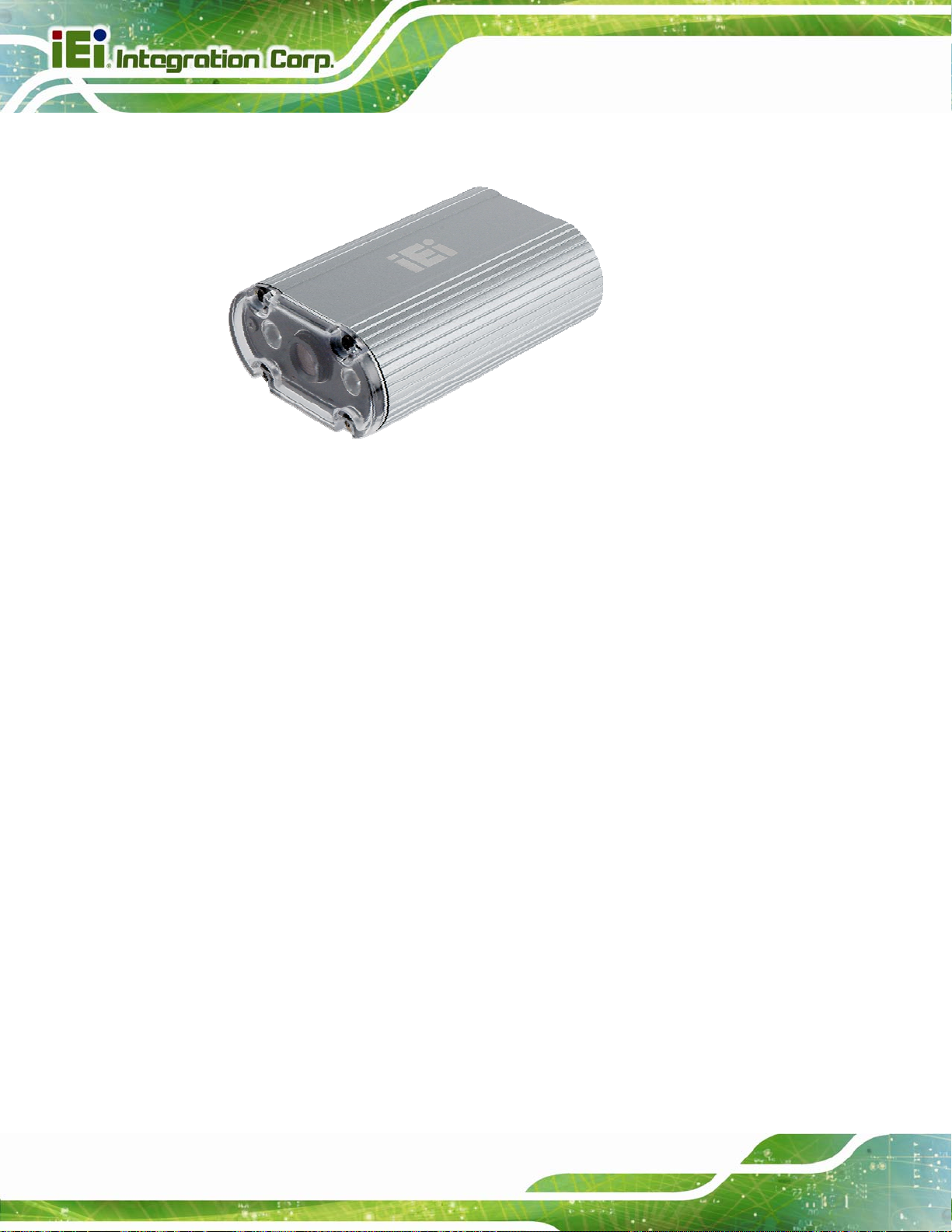
1.1 Overview
Figure 1-1: ITDB-100L
The ITDB-100L barcode reader is able to provide high-speed decoding and robust
ITDB-100L Barcode Reader
decoding for common distortion, which is suitable for industrial purpose such as the
high-speed production line. In addition, the ITDB-100L comes with a PC setup tool for
configuring the barcode reader and reading barcodes.
1.2 Features
The ITDB-100L features are listed below:
Image display: Capture/Preview
Trigger modes: One shot/Serial shot/Batch/Presentation
CMOS sensor configuration:
Image format: RAW/BMP/JPEG
Region of interest setting
Firmware upgradable via USB/Ethernet
Other configurations: Target Brightness/Illumination/Decode Timeout/Decode
o Automatic/Manual Exposure
o Gain
Interval
Page 2
Supports remote monitoring and control via Android phone and tablet
RoHS compliant
Page 12
ITDB-100L Barcode Reader
1.3 External Overview
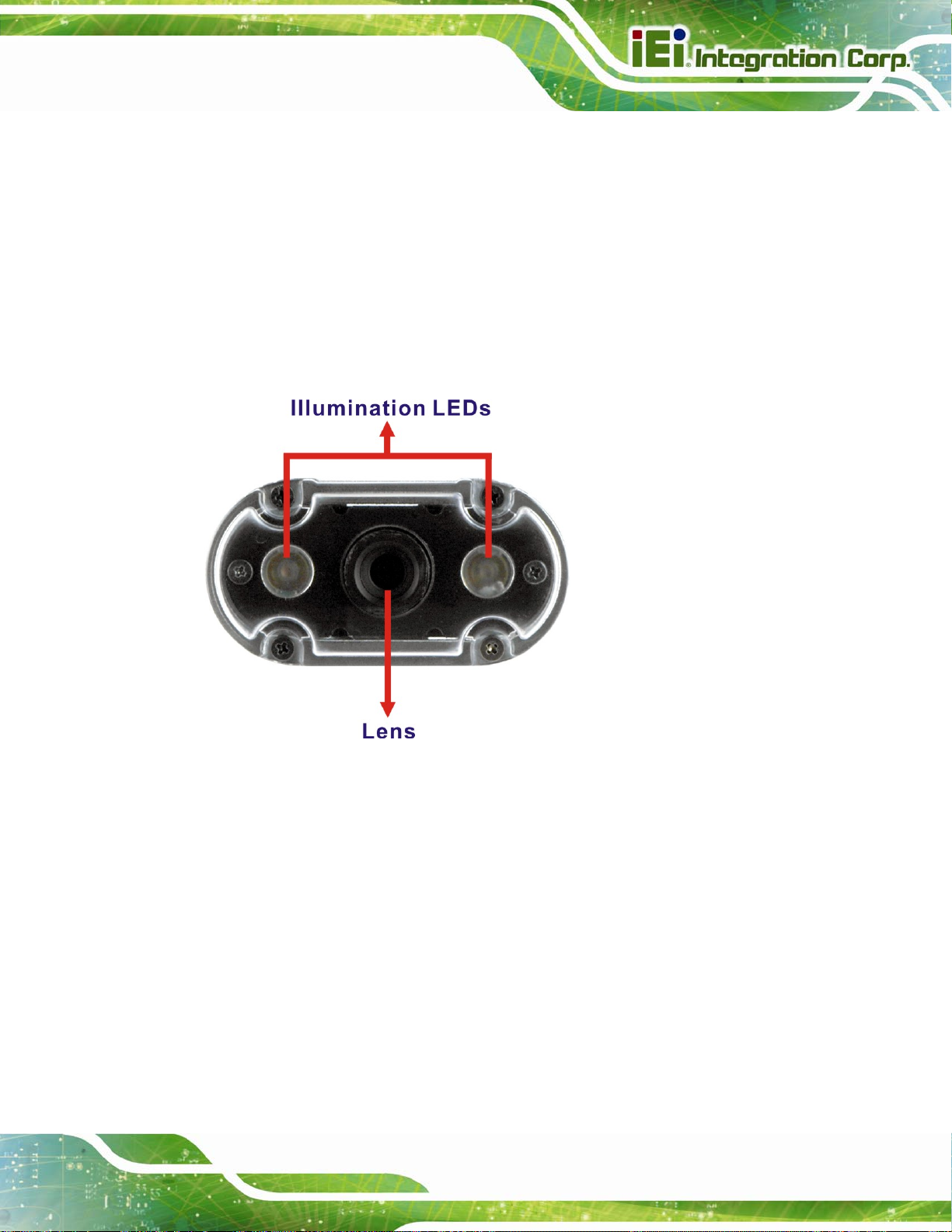
1.3.1 Front Panel
The ITDB-100L front panel contains:
2 x Illumination LEDs
1 x Lens
An overview of the front panel is shown in
Figure 1-2: ITDB-100L Front Panel
Figure 1-26.
1.3.2 Rear Panel
The ITDB-100L rear panel contains:
1 x 6-pin connector for trigger connection
1 x DC in jack
1 x Ethernet connector
1 x Micro USB port
1 x Power indicator
1 x Trigger and tuning control button
Page 3
Page 13
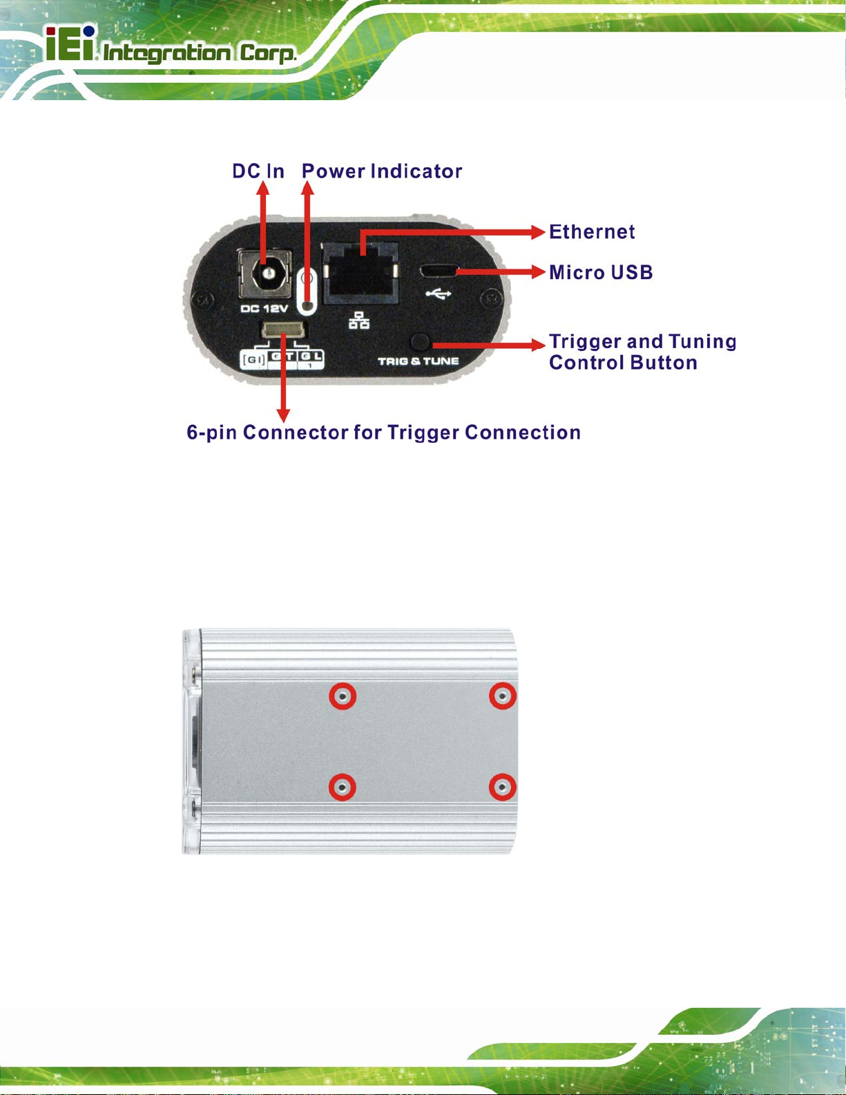
An overview of the rear panel is shown in 6Figure 1-3 below.
Figure 1-3: ITDB-100L Rear Panel
ITDB-100L Barcode Reader
1.3.3 Bottom Surface
The bottom surface of the ITDB-100L contains four retention screw holes for the mounting
bracket.
Figure 1-4: ITDB-100L Bottom Surface
Page 4
Page 14

ITDB-100L Barcode Reader
1.4 Technical Specifications
The ITDB-100L technical specifications are listed in Table 1-1.
Specifications
Supported 1D Symbologies
Supported 2D Symbologies
Sensor Major Specifications
Lens Major Specifications
Illumination Element (nm)
Code 39, code 93, interleaved 2 of 5, UPC/EAN (ISBN, UPCA,
UPCE, EAN13, EAN8), EAN 128, code 128, MSI, codabar
PDF-417, Micro PDF-417, QR Code/microQR Code,
Data Matrix
Sensor: 1/3 inch CMOS with global shutter
Resolution: 752 x 480
Acquisition: Max. rate 60fps
Focus: Fixed
Code resolution: ≥0.33 mm
Reading distance (at code resolution): 50 mm ~ 330 mm
2 x Red LEDs
Visible red light (λ= 650 nm ~ 660 nm)
1 x Micro USB port (USB 2.0 data transmission rate: 480 Mbit/s)
1 x Ethernet port (Ethernet data transmission rate: 10/100 Mbit/s)
1 x DC in jack (Φ2.5/Φ5.5)
I/O Interfaces
Operating Limits of the 6-pin
Connector for Trigger
Connection
1 x 6-pin connector for trigger connection
1 x Trigger and tuning control button
1 x Power indicator
Acoustic indicators: Beeper
Output of LED Flash Trigger
Current: 8mA
Voltage: 3.3VDC
Input of Interrupt Trigger
Current: 1.4mA@5VDC, 4mA@12VDC, 6.2mA@18VDC
Recommended operating voltage: 5VDC ~ 18VDC
Absolute voltage limits: 4.5VDC ~ 24VDC
Page 5
Page 15
Specifications
ITDB-100L Barcode Reader
Operating voltage: 12V/3.3A
Power Supply
Supported OS
Mechanical Specifications
Shock Resistance
Vibration
Power consumption:
Power on = 7.7 W
Max. PD = 9.9 W
Microsoft® Windows® XP 32-bit & 64-bit
Microsoft® Windows® Vista™ 32-bit & 64-bit
Microsoft® Windows® 7 32-bit & 64-bit
Housing: Die-casting aluminum
Housing color: Silver
Front cover: Transparent plastic
Weight: 290 g (without mounting bracket)
Dimensions (LxWxH): 89.8 mm x 62 mm x 32 mm
EN 60068-2-27 (2009-05)
MIL-STD-810F 514.5C-1 and IEC-60068-2-06
RoHS compliant
Operating temperature: 0°C ~ 50°C
Environment
Table 1-1: Technical Specifications
Storage temperature: -10°C ~ 60°C
Permissible relative humidity: 90% (non-condensing)
Ambient light safety: 2,000 lx, on code
Page 6
Page 16
ITDB-100L Barcode Reader
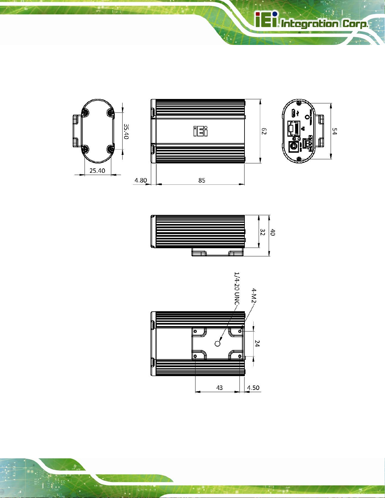
1.5 Dimensions
1.5.1 ITDB-100L Dimensions
Figure 1-5: ITDB-100L Dimensions (millimeters)
Page 7
Page 17
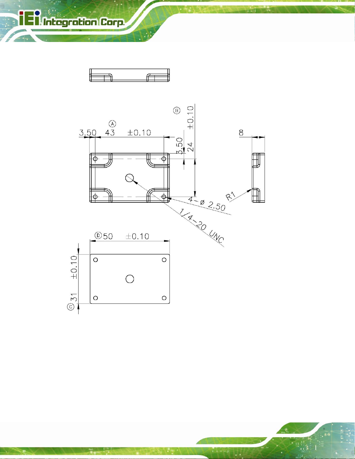
1.5.2 Mounting Bracket Dimensions
ITDB-100L Barcode Reader
Figure 1-6: Mounting Bracket Dimensions (millimeters)
Page 8
Page 18
ITDB-100L Barcode Reader
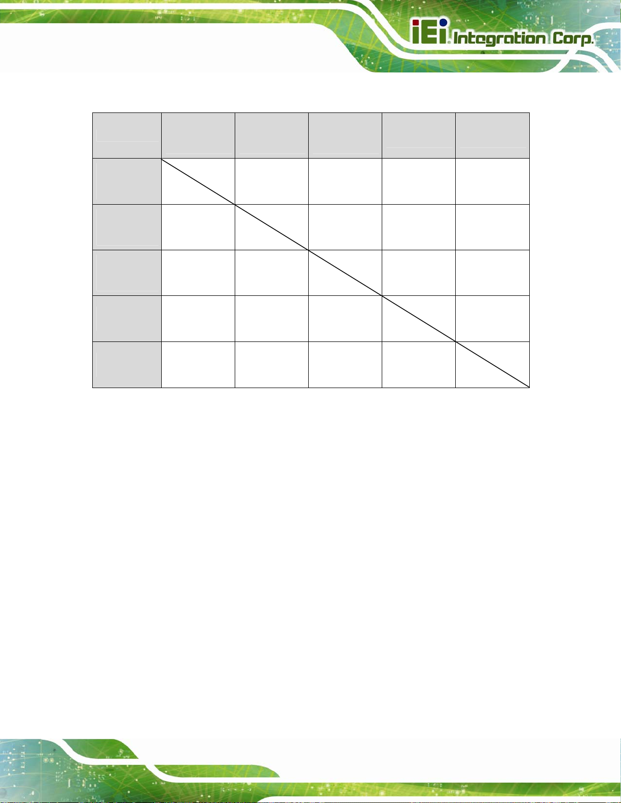
1.6 ITDB-100L Function Compatibility Guideline
USB
Function
USB
Connection
(via API)
LAN
Connection*
(via API)
USB
Keyboard
Wedge (HID)
Transfer to
Database
Built-in Web
Management
O: Compatible X: Incompatible
Connection
(via API)
O X O X
X X X X
O O X X
X X X X
LAN
Connection*
(via API)
USB
Keyboard
Wedge (HID)
O X O X
Transfer to
Database
Built-in Web
Management
* LAN connection interface includes the PC setup tool, Android app or QNAP NAS app. The users
can only choose one to connect to the ITDB-100L.
Page 9
Page 19

ITDB-100L Barcode Reader
Chapter
2
2 Unpacking
Page 10
Page 20

ITDB-100L Barcode Reader
2.1 Anti-static Precautions
WARNING:
Failure to take ESD precautions during installation may result in
permanent damage to the ITDB-100L and severe injury to the user.
Electrostatic discharge (ESD) can cause serious damage to electronic components,
including the ITDB-100L. Dry climates are especially susceptible to ESD. It is therefore
critical that whenever the ITDB-100L or any other electrical component is handled, the
following anti-static precautions are strictly adhered to.
Wear an anti-static wristband: Wearing a simple anti-static wristband can
help to prevent ESD from damaging the board.
Self-grounding: Before handling the board, touch any grounded conducting
material. During the time the board is handled, frequently touch any
conducting materials that are connected to the ground.
Use an anti-static pad: When configuring the ITDB-100L, place it on an
antic-static pad. This reduces the possibility of ESD damaging the ITDB-100L.
2.2 Unpacking Precautions
When the ITDB-100L is unpacked, please do the following:
Follow the anti-static precautions outlined in Section
Make sure the packing box is facing upwards so the ITDB-100L does not fall
out of the box.
Make sure all the components shown in Section
2.1.
2.3 are present.
Page 11
Page 21
2.3 Unpacking Checklist
NOTE:
If some of the components listed in the checklist below are missing,
please do not proceed with the installation. Contact the IEI reseller or
vendor you purchased the ITDB-100L from or contact an IEI sales
representative directly. To contact an IEI sales representative, please
ITDB-100L Barcode Reader
send an email to
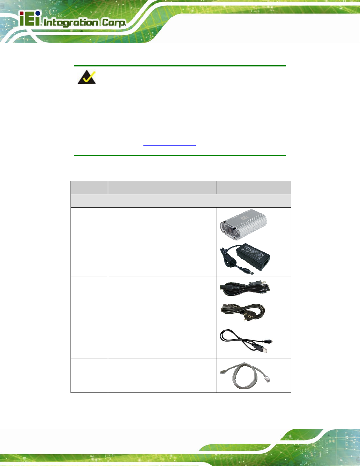
The ITDB-100L is shipped with the following components:
Quantity Item Image
Standard
1 ITDB-100L
1 Power adapter
(P/N: 63000-FSP040DGAA1106-RS)
1 Power cord (US)
(P/N: 32701-000700-100-RS)
1 Power cord (EU)
sales@ieiworld.com.
Page 12
(P/N: 32702-000200-100-RS)
1 Micro USB cable
(P/N: 32001-008501-100-RS)
1 Ethernet cable
(P/N: 32000-113100-RS)
Page 22
ITDB-100L Barcode Reader
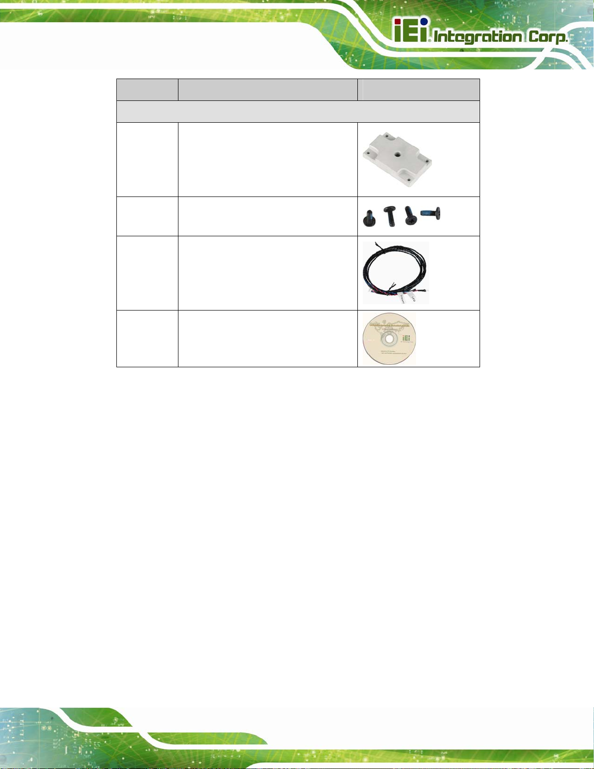
Quantity Item Image
Standard
1 Mounting bracket
(P/N: 42110-0172C0-00-RS-N)
4 Mounting bracket screw
(P/N: 44045-020061-RS)
1 Trigger connection cable
1 User manual and utility CD
Page 13
Page 23

ITDB-100L Barcode Reader
Chapter
3
3 Installation
Page 14
Page 24

ITDB-100L Barcode Reader
3.1 Installation Precautions
During installation, be aware of the precautions below:
Read the user manual: The user manual provides a complete description of
the ITDB-100L, installation instructions and configuration options.
DANGER! Disconnect Power: Power to the ITDB-100L must be
disconnected during the installation process. Failing to disconnect the power
may cause severe injury to the body and/or damage to the system.
Qualified Personnel: The ITDB-100L must be installed and operated only by
trained and qualified personnel. Maintenance, upgrades, or repairs may only
be carried out by qualified personnel who are familiar with the associated
dangers.
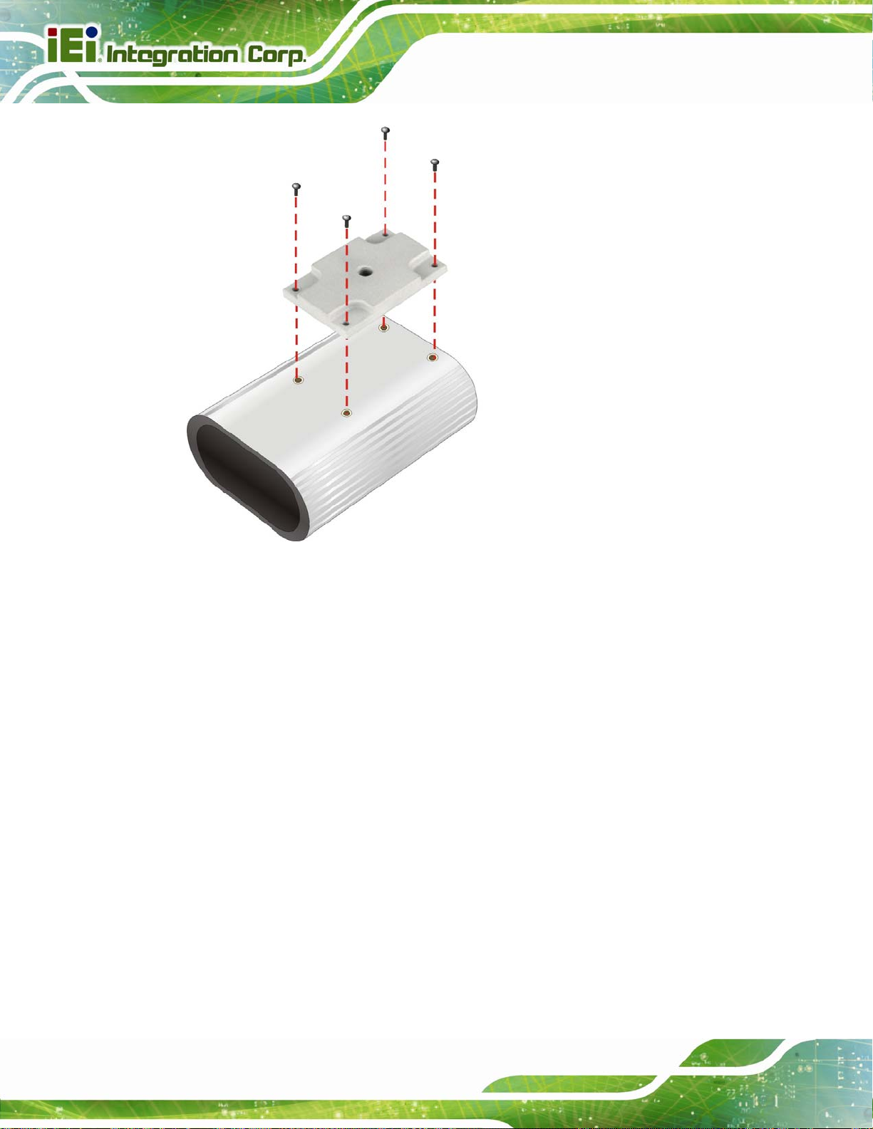
3.2 Mounting the ITDB-100L
The ITDB-100L is shipped with a mounting bracket that allows the ITDB-100L to be
mounted onto an object with corresponding mounting screw, such as a tripod. To mount
the ITDB-100L onto an object using the mounting bracket, please follow the steps below.
Step 1: Attach the mounting bracket to the bottom panel of the ITDB-100L. Secure the
bracket to the ITDB-100L with the four supplied retention screws. See
3-1.
Figure
Page 15
Page 25
ITDB-100L Barcode Reader
Figure 3-1: Securing the Mounting Bracket to the ITDB-100L
Step 2: Mount the ITDB-100L to an object with corresponding mounting screw, for
example, a tripod. Align the threaded hole on the mounting bracket with the
mounting screw, place the ITDB-100L over the object, and then spin the
ITDB-100L until it is secure to the object (
Figure 3-2).
Page 16
Page 26

ITDB-100L Barcode Reader
Figure 3-2: Mounting the ITDB-100L
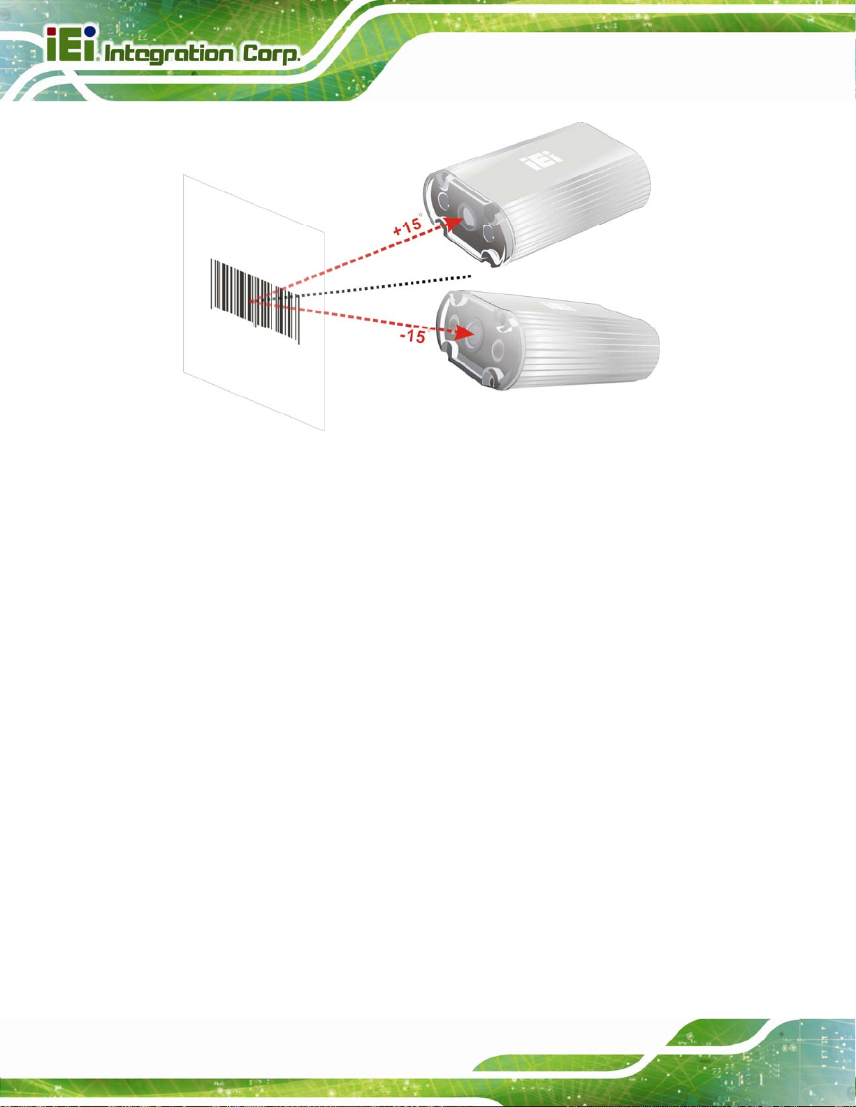
Step 3: To avoid reflection and glare from the scanned object and label surfaces, it is
recommended to mount the barcode reader at a 15º angle from vertical to the
scanned object (
Figure 3-3).
Page 17
Page 27
ITDB-100L Barcode Reader
Figure 3-3: Adjusting the ITDB-100L
3.3 External Peripheral Interface Connectors
The ITDB-100L has the following connectors. Detailed descriptions of the connectors can
be found in the subsections below.
6-pin connector for trigger connection
Ethernet
Micro USB
3.3.1 6-Pin Connector for Trigger Connection
The 6-pin connector on the rear panel allows connection to an external trigger device or a
sensor. The user can use the supplied trigger connection cable to connect the ITDB-100L
to an external device.
Step 1: Locate the 6-pin connector. The location of the 6-pin connector is shown in
Power input
Figure 1-3.
Page 18
Page 28

ITDB-100L Barcode Reader
Step 2: Align the connectors. Align the 6-pin plug on the trigger connection cable with
the 6-pin connector on the ITDB-100L. See
Figure 3-4.
Figure 3-4: Trigger Connection
Step 3: Insert the trigger connection cable 6-pin plug. Once aligned, gently insert the
trigger connection cable 6-pin plug into the 6-pin connector on the ITDB-100L.
Step 4: Connect the other end of the trigger connection cable to an external device.
The pinouts of the 6-pin connector are shown below:
Pin Color Signal
1 Red Output of LED Flash Trigger
2 Black Ground for the Output of LED Flash Trigger
3 Blue Input of Interrupt Trigger
4 Black Ground for the Input of Interrupt Trigger
Page 19
Page 29

Pin Color Signal
5 N/A (Reserved)
6 N/A (Reserved)
Table 3-1: Connector Pinouts
3.3.1.1 Digital Output Wiring
ITDB-100L Barcode Reader
Figure 3-5: Digital Output Wiring
3.3.1.2 Digital Input Wiring
Page 20
Figure 3-6: Digital Input Wiring
Page 30

ITDB-100L Barcode Reader
3.3.1.3 Digital Input and Output Connection
The below figure demonstrates a possible way of digital input and output connection.
Figure 3-7: Digital Input and Output Connection
Page 21
Page 31
3.3.2 Ethernet Connector
The ITDB-100L is equipped with an Ethernet connector that allows connection to a
computer/network hub. Follow the steps below to connect the ITDB-100L to a
computer/network hub by using the supplied Ethernet cable.
Step 1: Locate the Ethernet connector. The location of the Ethernet connector is
ITDB-100L Barcode Reader
shown in
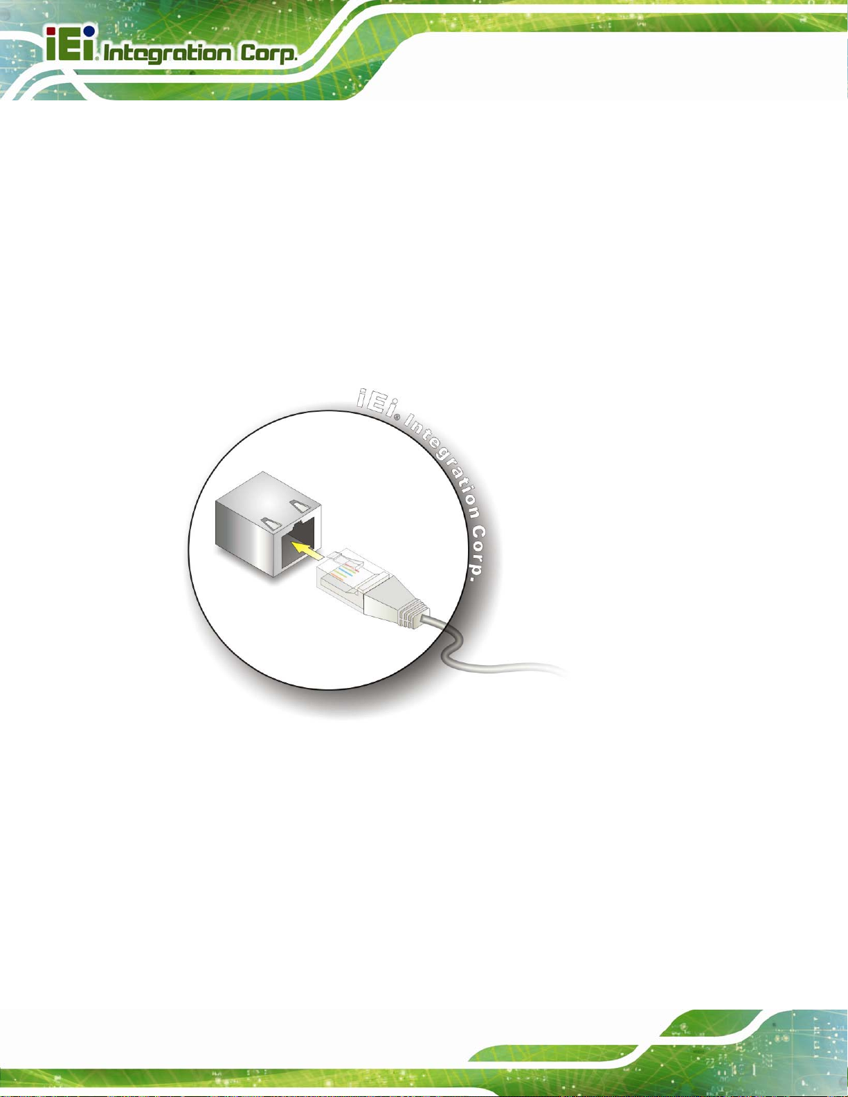
Step 2: Align the connectors. Align the Ethernet connector on the LAN cable with the
Ethernet connector on the ITDB-100L. See
Figure 1-3.
Figure 3-8.
Page 22
Figure 3-8: Ethernet Connection
Step 3: Insert the LAN cable Ethernet connector. Once aligned, gently insert the LAN
cable Ethernet connector into the Ethernet connector on the ITDB-100L.
Step 4: Connect the other end of the Ethernet cable to the Ethernet connector of a
computer/network hub.
Page 32

ITDB-100L Barcode Reader
3.3.2.1 Network Connection
The below figure demonstrates a possible way of network connection.
Figure 3-9: Network Connection
Page 23
Page 33

3.3.3 Micro USB Connector
The ITDB-100L is equipped with a Micro USB connector that allows connection to a
computer. Follow the steps below to connect the ITDB-100L to a computer by using the
supplied Micro USB cable.
Step 1: Locate the Micro USB connector. The location of the Micro USB connector is
ITDB-100L Barcode Reader
shown in
Step 2: Align the Micro USB connectors. Align the Micro USB connector on the Micro
USB cable with the Micro USB connector on the ITDB-100L. See
Figure 1-3.
Figure 3-10.
Page 24
Figure 3-10: Micro USB Connection
Step 3: Insert the Micro USB cable Micro USB connector. Once aligned, gently insert
the Micro USB cable Micro USB connector into the Micro USB connector on the
ITDB-100L.
Step 4: Connect the other end (USB Standard Type A) of the Micro USB cable to the
USB Type A receptacle of a computer. See
Figure 3-11.
Page 34

ITDB-100L Barcode Reader
Figure 3-11: USB Standard Type A Connection
3.3.3.1 USB Keyboard Wedge
After connecting the ITDB-100L to the USB port of a computer, the ITDB-100L will be
recognized by the computer as a second keyboard. When the ITDB-100L scans a barcode
without any API opened, the barcode data goes into the computer just as if it were being
typed on a keyboard.
3.3.4 Power Input Connector
Step 1: Locate the power input connector. The location of the power input connector is
shown in
Step 2: Connect the supplied power adapter to the power input connector of the
ITDB-100L.
Step 3: Connect the power adapter to a power source by using the supplied power cord.
Step 4: A beep should be generated, indicating that the ITDB-100L is fed with power.
Figure 1-3.
Page 25
Page 35

3.4 Reading Distance and Field of View
The following figure provides the supported reading distances and field of view for the
ITDB-100L.
ITDB-100L Barcode Reader
Page 26
Figure 3-12: Reading Distance and Field of View
Page 36

ITDB-100L Barcode Reader
4 Driver and PC Setup
Chapter
4
Tool Installation
Page 27
Page 37

4.1 Overview
A CD is shipped with the barcode reader. The CD contains the device driver and
application setup file. The driver must be installed to the connected computer so that the
barcode reader can be recognized by the system.
4.2 Driver Installation
To install the device driver, please follow the steps below.
Step 1: Connect the ITDB-100L to the computer and power supply. A beep should be
generated when the ITDB-100L is fed with power.
Step 2: Go to Control Panel > System > Hardware > Device Manager. A list of system
hardware devices appears.
ITDB-100L Barcode Reader
Step 3: Right-click ITDB-100L FW(x.xx) which has question mark next to it (this means
Windows does not recognize the device).
Step 4: Select Update Driver… (
Figure 4-1).
Page 28
Figure 4-1: Device Manager
Page 38

ITDB-100L Barcode Reader
Step 5: The Found New Hardware Wizard appears (Figure 4-2). Select No, not this
time, then click Next to continue.
Figure 4-2: Found New Hardware Wizard
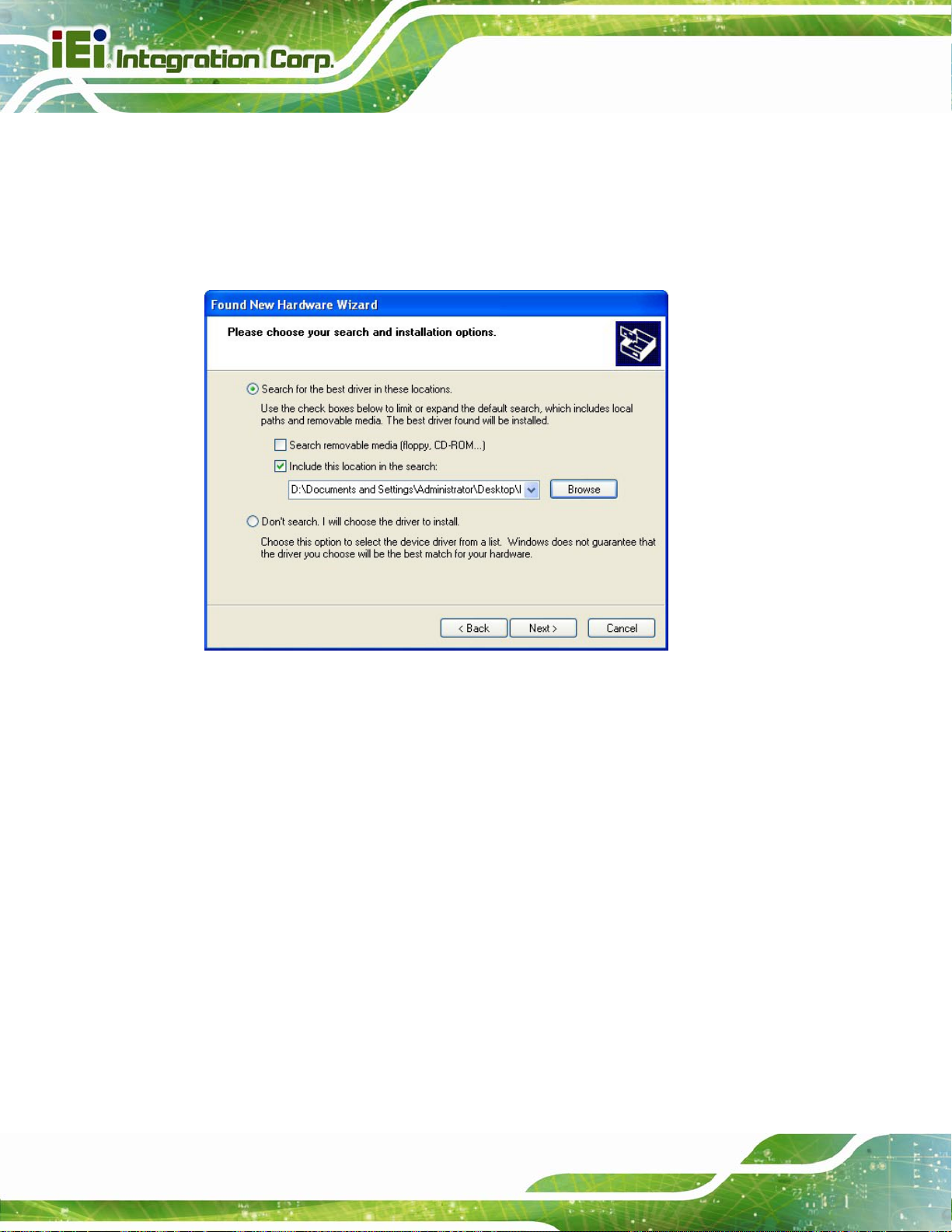
Step 6: Select Install from a list or specific location, then click Next to continue.
Figure 4-3).
(
Figure 4-3: Install from Specific Location
Page 29
Page 39
Step 7: Insert the driver CD into an optical disk drive connected to the system.
ITDB-100L Barcode Reader
Step 8: Select Include this location in the search (
Step 9: Click Browse to select “X:\” directory in the Locate File window, where “X:\” is
the system CD drive.
Figure 4-4).
Figure 4-4: Locate Driver Files
Step 10: Click Next to continue.
Step 11: Driver Installation is performed as shown in
Figure 4-5.
Page 30
Page 40

ITDB-100L Barcode Reader
Figure 4-5: Driver Installation
Step 12: When the driver installation is completed, the following window appears. Click
Finish to exit.
Figure 4-6: Driver Installation Complete
Page 31
Page 41

4.3 Setup Tool Installation
To install the barcode reader setup tool, please follow the steps below.
NOTE:
The setup tool supports the following OS versions:
Microsoft® Windows® XP 32-bit and 64-bit
Microsoft® Windows® Vista™ 32-bit and 64-bit
Microsoft® Windows® 7 32-bit and 64-bit
Step 1: Ensure that the ITDB-100L is connected to the computer and power supply. If
the barcode reader cannot be recognized by the computer, install the device
ITDB-100L Barcode Reader
driver. Refer to Section
Step 2: Insert the driver CD.
Step 3: Locate the ITDB Barcode Verifier file in the driver CD. Double click the setup
file to start the installation.
Step 4: The InstallShield Wizard welcome window appears. Click Next to start.
4.2 for details.
Page 32
Figure 4-7: InstallShield Wizard
Page 42

ITDB-100L Barcode Reader
Step 5: Select a folder for application installation (Figure 4-8). Click Next to continue.
Figure 4-8: Select Installation Folder
Step 6: The following screen appears. Click Install to start the installation.
Figure 4-9: Ready for Installation
Step 7: The system starts installing the application.
Page 33
Page 43

Step 8: When the application installation is completed, the following window appears.
Click Finish to exit. Step 0:
ITDB-100L Barcode Reader
Figure 4-10: Installation Complete
Page 34
Page 44

ITDB-100L Barcode Reader
5 Barcode Reader
Chapter
5
Setup Tool
Page 35
Page 45

5.1 Overview
The barcode reader setup tool allows configuration of the ITDB-100L via a computer.
Refer to the following sections for detailed information.
NOTE:
The setup tool supports the OS versions listed below:
Microsoft® Windows® XP 32-bit & 64-bit
Microsoft® Windows® Vista™ 32-bit & 64-bit
Microsoft® Windows® 7 32-bit & 64-bit
5.2 Launching the Setup Tool
ITDB-100L Barcode Reader
Step 1: Ensure that the ITDB-100L is connected to the computer and power supply. A
beep should be generated when the ITDB-100L is fed with power.
Step 2: If the setup tool is installed to the connected computer, an ITDB Barcode
Verifier (
the icon to launch the barcode reader setup tool.
Figure 5-1: Setup Tool Icon
Figure 5-1) icon should appear on the Windows desktop. Double click
Page 36
Page 46

ITDB-100L Barcode Reader
5.3 Initial Screen
After double-clicking the ITDB Barcode Verifier icon on the Windows desktop, the initial
screen of the setup tool appears (
enter the SETTING menu. When using the setup tool for the first time, refer to Section
Figure 5-2: Initial Screen
Figure 5-2). Click Sync Settings & Decode Now to
5.4.
5.4 Initial Setting
Step 1: When using the setup tool for the first time, click Initial Setting in the initial screen
Figure 5-2).
(
Step 2: The system detects the available connection type (
Figure 5-3).
Page 37
Page 47

Figure 5-3: Detecting the Available Connection Type
ITDB-100L Barcode Reader
Step 3: Click LAN or Micro USB depending on the connection type to the computer
Figure 5-4). A confirmation dialog screen should appear. Click OK to confirm
(
the selection.
Page 38
Figure 5-4: Connection Type Selection
Page 48

ITDB-100L Barcode Reader
Step 4: When the connection is complete, two beeps should be generated, and the
connection status field displays Connected as shown in
Figure 5-5: Connection Status
Figure 5-5.
Step 5: In the Configuration page (
SETTING menu to configure the barcode reader settings manually.
For automatic setup, refer to Section
5.5 Automatic Setup
The user may select automatic setup to allow the ITDB-100L to adjust to the optimal
settings for decoding an image successfully. Follow the steps below to use the automatic
setup.
Step 1: Click Auto Setup in the Configuration page (
Figure 5-5), click Manual Setup to enter the
5.5 for details.
Figure 5-6).
Page 39
Page 49

Figure 5-6: Auto Setup
ITDB-100L Barcode Reader
Step 2: Automatic setup is performed as shown in
Figure 5-7: Automatic Setup
Figure 5-7.
Page 40
Step 3: When the setup is complete, the screen in
enter the VERIFICATION menu.
If automatic setup is failed, click Retry to start automatic setup again.
Figure 5-8 appears. Click NEXT to
Page 50

ITDB-100L Barcode Reader
Figure 5-8: Setup Complete
5.6 Verification Menu
In the VERIFICATION menu, the user can set up the trigger behavior, scanned result
format and region of interest, load scanned images, and set a barcode image to training
mode.
Figure 5-9: Verification
Page 41
Page 51
Trigger mode:
The user can set the trigger behavior as One Shot, Serial Shot, Batch or
Presentation. When setting to Serial Shot, the ITDB-100L scan images
continuously until an image is decoded successfully.
Decode result format:
The user can set the scanned result format as Image & Decode, Image or
Decode.
Trigger button:
The user can click the button to trigger the ITDB-100L.
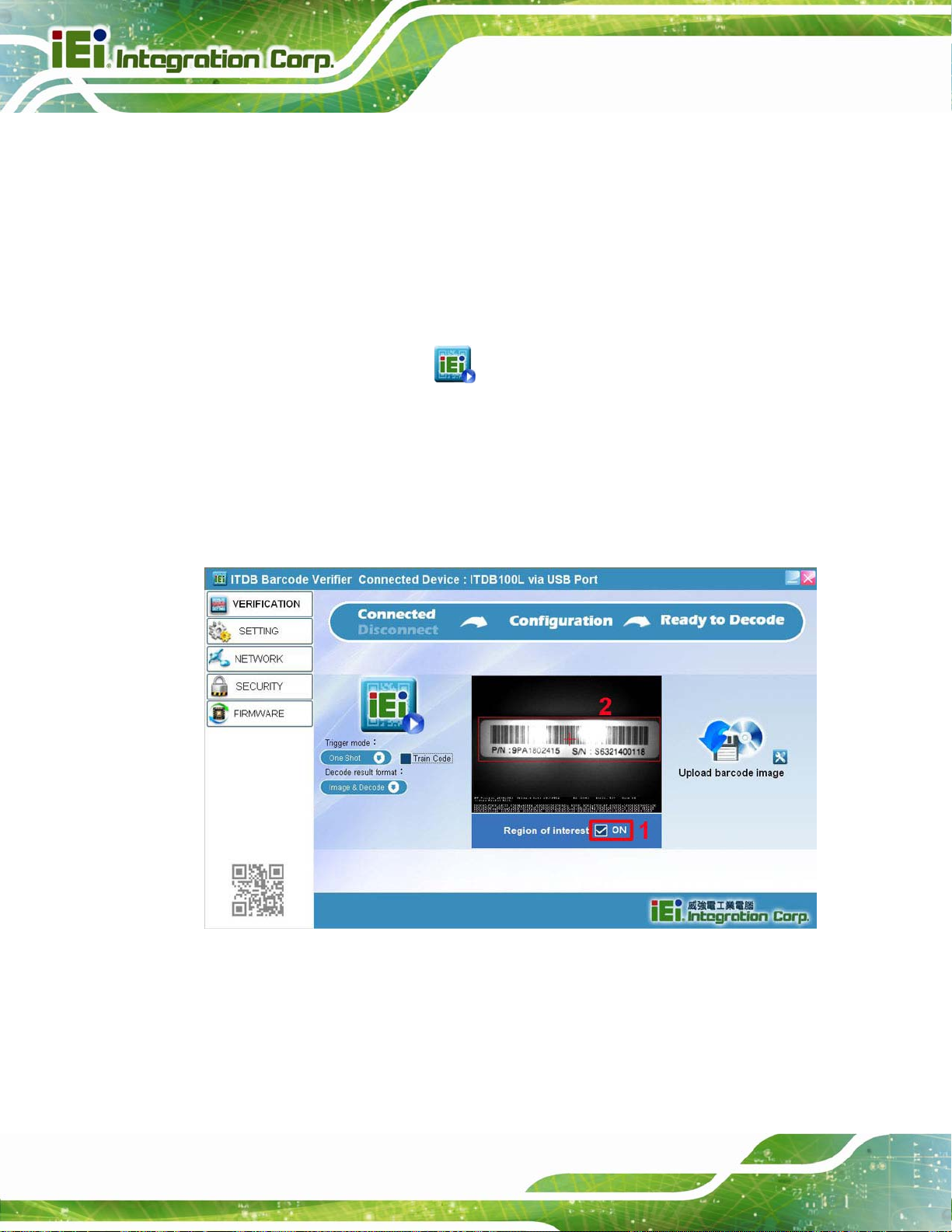
5.6.1 Region of Interest
The Region of Interest (ROI) item allows setting the scan area of the barcode reader.
Follow the steps below to use the ROI function.
ITDB-100L Barcode Reader
Step 1: Click the check box to enable the ROI function (
Step 2: Draw a frame to select the desired scan area (
Figure 5-10: Setting the Region of Interest
Figure 5-10).
Figure 5-10).
Page 42
Step 3: To lock the ROI setting, right-click the screen, and then select Lock
Figure 5-11). The frame turns into green, indicating that the ROI setting is
(
locked.
The user can select Full Screen to set the ROI to full screen mode.
Page 52

ITDB-100L Barcode Reader
Figure 5-11: Locking the ROI Setting
5.6.2 Training Mode
The user can set a scanned barcode as a sample image so that the barcode reader
decodes only the same barcode type and size. Follow the steps below to set a barcode
image to training mode.
Step 1: Click the Train Code item (
The user can also press and hold the trigger and tuning control button for four
seconds to start the function. Refer to
Figure 5-12) to start the training mode function.
Figure 1-3 for the location of the button.
NOTE:
The Train Code item can also be found in the SETTING and
Symbology Setting menus
Page 43
Page 53

ITDB-100L Barcode Reader
Figure 5-12: Train Code Item
Step 2: Four beeps are being generated, the illumination LEDs start to flash and the
screen in
Figure 5-13: Training Mode Timer is Started
Step 3: The user has to click the Click And Train button (
ITDB-100L within twelve seconds after the timer is started.
The user can also trigger the ITDB-100L by pressing the trigger and tuning
control button once or even through an external sensor.
Figure 5-13 appears, indicating that the training mode timer is started.
Figure 5-13) to trigger the
Page 44
Step 4: When a barcode is set as a sample image successfully, two beeps should be
generated and the T rain Code item displays
If the barcode training is failed, four beeps will be generated.
.
Page 54

ITDB-100L Barcode Reader
Figure 5-14: Trained Mode
Step 5: To disable the training mode, click the Train Code item or press and hold the
trigger and tuning control button for four seconds.
5.6.3 Loading Saved Images
The user can load the saved images to view their detailed information. When a scanned
barcode is being saved, it should be stored to the Save Image folder located at the same
folder where the setup tool has been installed.
To load an image:
To load an image at once, click the icon indicated in
select the image to upload to the setup tool.
Figure 5-15, and then
Figure 5-15: Loading an Image
Page 45
Page 55

To load all the images of a folder or selected images:
To load all the images of a folder or selected images, click the icon indicated
in
Figure 5-16, and then select to load images by folder or by selection.
ITDB-100L Barcode Reader
Figure 5-16: Loading Images
Page 46
Page 56

ITDB-100L Barcode Reader
5.7 Settings Menu
Click SETTING to display the Settings menu (Figure 5-17). In this menu, the user can
configure detailed settings for the barcode reader.
Figure 5-17: Settings
Trigger mode:
The user can set the trigger behavior as One Shot, Serial Shot, Batch or
Presentation. When setting to Serial Shot, the ITDB-100L scans images
continuously until an image is decoded successfully.
Decode result format:
The user can set the scanned result format as Image & Decode, Image or
Decode.
Auto Exposure:
Check the ON box to let the device adjust the exposure value automatically.
NOTE:
When the Auto Exposure function is turned on, the Manual Expos ure,
GAIN and LED Brightness items will not be available to set up.
Page 47
Page 57

Manual Exposure:
Move the slide bar or enter the value to set the exposure time.
GAIN:
Move the slide bar or enter the value to adjust the gain setting.
LED Brightness:
Move the slide bar or enter the value to adjust the LED brightness.
Decode timeout(ms):
Move the slide bar or enter the value to adjust the decode time-out setting.
Decode interval(ms):
Move the slide bar or enter the value to adjust the decode interval setting.
Train Code:
ITDB-100L Barcode Reader
Refer to Section
TEST button:
Click the TEST button to scan a barcode by using the current settings
SAVE button:
Click the SAVE button to save the current settings as a setting file.
LOAD button:
Click the LOAD button to load a saved setting file to the ITDB-100L.
Symbology Setting:
Click the
which allows the user to select the supported barcode types and train a
barcode image. When a barcode is being trained, the user cannot select the
supported barcode types. For using the training mode, refer to Section
for details.
5.6.2 for details.
icon to bring up the Symbology Setting menu (Figure 5-18)
NOTE:
5.6.2
Page 48
The user can click the icon located in front of a barcode to
configure its properties.
Page 58

ITDB-100L Barcode Reader
Figure 5-18: Symbology Settings
5.8 Network Menu
Click NETWORK on the left pane of the setup tool to bring up the Network Setting menu
(
Figure 5-19). In this menu, the user can configure network settings and set up a device
name for the barcode reader.
Figure 5-19: Network Setting
Page 49
Page 59

Address:
Click DHCP to enable the DHCP function or set up the IP address, mask and
gateway manually.
Server IP:
Click Enable, enter the server IP, and then click Save IP to save the keyed-in
server IP.
DNS IP:
Click Enable, enter the DNS IP, and then click Save DNS IP to save the
keyed-in DNS IP.
Device Name:
Enter a name and click Set Device Name to set up a device name for the
barcode reader.
5.9 Security Menu
ITDB-100L Barcode Reader
Click SECURITY on the left pane of the setup tool to bring up the Change Password menu
(
Figure 5-20). In this menu, the user can set up a password for the ITDB-100L. When a
password is set, the user has to enter the password before configuring the barcode
reader.
NOTE:
The default old password is 1234.
If the user forgets the password, it is necessary to enter the Backup
Mode to reset the password. Refer to Section
and exit the backup mode.
5.10.3 on how to enter
Page 50
Page 60

ITDB-100L Barcode Reader
Figure 5-20: Change Password
Page 51
Page 61

Y
5.10 FW Upgrade and Backup Mode
This section covers how to upgrade the device FW and enter the backup mode when the
FW upgrade is failed or the ITDB-100L is failed to restart.
5.10.1 FW Upgrade Flow Chart
Start
Upgrade the FW (refer
to Section 5.9.2)
The ITDB-100L
restarts automatically.
ITDB-100L Barcode Reader
Remove the
power supply
Reconnect the power
supply and enter the
Backup Mode (refer
to Section 5.9.3)
The ITDB-100L
restarts suc cessfully
and the FW is upgraded
to the latest version
es
Done
Upgrade the FW (refer
to Section 5.9.2)
No
Remove the
power supply,
then reconnect it
Page 52
Page 62

ITDB-100L Barcode Reader
5.10.2 Upgrading the FW
Follow the steps below to upgrade the FW.
Step 1: Click FIRMWARE on the left pane of the setup tool to bring up the Firmware
Upgrade menu (
The user can check the current firmware version from the menu.
Step 2: Click Path to locate the firmware file.
Step 3: Click Upgrade F/W to start updating the firmware.
Figure 5-21: FW Upgrade
Step 4: When the FW upgrade is complete, the ITDB-100L restarts automatically.
Figure 5-21).
Step 5: If the FW upgrade is failed or the ITDB-100L is failed to reboot, the user needs to
put the ITDB-100L into the backup mode and upgrade the device FW in the
backup mode. Refer to Section
mode.
5.10.3 on how to enter and exit the backup
Page 53
Page 63

5.10.3 Backup Mode
When the FW upgrade is failed or the ITDB-100L is failed to reboot, the ITDB-100L needs
to enter the backup mode and upgrade the FW in the backup mode. Follow the steps
below to enter and exit the backup mode.
Step 1: Before the ITDB-100L is connected to the power supply, press and hold the
ITDB-100L Barcode Reader
trigger and tuning control button. Refer to
button.
Step 2: Connect the ITDB-100L to the power supply. When a beep is generated from the
ITDB-100L, release the trigger and tuning control button. The ITDB-100L is in
backup mode now.
Refer to Section
Step 3: To exit the backup mode, remove the power supply, and then reconnect it to the
ITDB-100L.
5.10.2 on how to upgrade the device FW.
Figure 1-3 for the location of the
Page 54
Page 64

ITDB-100L Barcode Reader
Chapter
6
6 Configuring the ITDB-100L
via
an Android Device
Page 55
Page 65

ITDB-100L Barcode Reader
6.1 Overview
The barcode reader settings can be configured by an Android device. Refer to the
following sections for detailed information.
NOTE:
The screenshots in this chapter may vary by different Android devices
and are for reference purposes only.
6.2 Installing and Launching the Android App
NOTE:
It is recommended to install the app to the Android OS 4.1.2 and above.
To install and launch the Android app, please follow the steps below.
Step 1: Download the Barcode Reader QuickSet app from the Google Play and install
it to the Android device.
Step 2: When the app is installed, the BarCode Reader icon will be shown on the
application page (
Figure 6-1).
Page 56
Page 66

ITDB-100L Barcode Reader
Figure 6-1: App Icon
Step 3: Tap the app icon to launch it.
Page 57
Page 67

6.3 Settings Menu
The initial screen of the app is a settings menu, allowing the user to set up the captured
ITDB-100L Barcode Reader
image format and the maximum quantity of captured images (
settings are done, tap OK to enter the barcode reader list screen.
Figure 6-2). When the
Figure 6-2: Settings Menu
Image Format:
Sets up the captured image format between Bitmap or Jpeg.
Maximum of recording images:
Sets up the maximum quantity of captured images.
Page 58
Page 68

ITDB-100L Barcode Reader
6.4 Barcode Reader List
NOTE:
Ensure that the DHCP Server function of the wireless router is turned
off. To disable the DHCP Server function, refer to the user manual of
the wireless router.
The barcode reader list screen displays the ITDB-100L barcode readers found by the
Android device and allows the user to select a barcode reader to configure its settings.
Figure 6-3: Barcode Reader List
Page 59
Page 69

ITDB-100L Barcode Reader
6.5 Configuring the Barcode Reader to Decode an Image Successfully
When a barcode reader is selected in the barcode reader list screen, the screen in Figure
6-4 will be shown. Refer to the following subsections to configure the selected barcode
reader so that a barcode image can be decoded successfully.
Figure 6-4: Decoding Image Screen
6.5.1 Live View Function
The live view function allows the user to preview the barcode. Follow the steps below to
use the live view function.
Page 60
Page 70

ITDB-100L Barcode Reader
Step 1: Switch the capture mode icon to .
Step 2: Adjust the barcode reader or scanned object until the barcode is shown on the
scan area screen.
6.5.2 Using the External Sensor to Trigger the Barcode Reader
Follow the steps below to use the external sensor to trigger the barcode reader.
Step 1: Switch the capture mode icon to
Step 2: When the external sensor triggers the barcode reader, the captured image and
decoding result will be shown on the screen.
.
6.5.3 Single Image Decoding
Follow the steps below to proceed with single image decoding.
Step 1: Switch the capture mode icon to
Step 2: Tap
Step 3: If the barcode is successfully decoded, the decoding process will stop.
Otherwise, the decoding process will continue.
Step 4: During decoding, tap any icon on the screen as shown in
key on the Android device to stop decoding.
to start single image decoding.
.
Figure 6-4 or the Back
6.5.4 Continuous Image Decoding
Follow the steps below to proceed with continuous image decoding.
Step 1: Switch the capture mode icon to
Step 2: Tap
to stop.
to start continuous image decoding. During decoding, tap
.
Page 61
Page 71

6.5.5 Setting an Image to Training Mode
The user can set a scanned barcode as a sample image so that the barcode reader
decodes only the same barcode type and size. Follow the steps below to set a barcode
image to training mode by using the Android app.
NOTE:
The training mode function can also be enabled by using the PC setup
ITDB-100L Barcode Reader
tool or the trigger and tuning control button. Refer to Section
details.
Step 1: Tap to start the training mode function.
Step 2: Four beeps are being generated, the illumination LEDs start to flash and the
training mode button turns to
started.
Step 3: The user has to tap
seconds after the timer is started.
Step 4: When successfully set a barcode as a sample image, two beeps should be
or to trigger the ITDB-100L within twelve
, indicating that the training mode timer is
5.6.2 for
Page 62
generated and the training mode button turns to
If the barcode training is failed, four beeps will be generated.
Step 5: To disable the training mode, tap
,
.
Page 72

ITDB-100L Barcode Reader
6.5.6 Parameter Settings
Tap to bring up the parameter settings bar at the bottom of the screen as shwon in
Figure 6-5.
Figure 6-5: Parameter Settings
6.5.6.1 Automatic Setting
The (automatic) option allows the barcode reader to adjust to its optimal settings
according to the barcode reading environment.
Step 1: Tap
Step 2: Tap
Step 3: When the automatic setting is done, the
will appear, and the atutomatic setting process will stop. Tap
to start automatic setting.
to stop automatic setting.
message
or the Back
Page 63
Page 73

key on the Android device to return to the barcode reader list screen. Then the
automatic setting parameters will be stored to the barcode reader.
ITDB-100L Barcode Reader
Step 4: When the automatic setting is failed, the
will appear, and the atutomatic setting process will stop. Then all the parameters
will be restored to the last-saved settings.
6.5.6.2 LED Brightness
The (LED brightness) option allows the user to adjust the LED brightness.
Step 1: Tap
the percentage of the LED brightness.
, then drag the slider at the bottom of the screen (Figure 6-6) to adjust
message
Page 64
Figure 6-6: Percentage of LED Brightness
Step 2: Tap
list screen. Then the brightness parameter will be stored to the barcode reader.
or the Back key on the Android device to return to the barcode reader
Page 74

ITDB-100L Barcode Reader
6.5.6.3 Exposure Time
The (exposure time) option allows the user to adjust the exposure time.
Step 1: Tap
the exposure time.
, then drag the slider at the bottom of the screen (Figure 6-7) to adjust
Figure 6-7: Exposure Time
Step 2: Tap
list screen. Then the exposure time parameter will be stored to the barcode
reader.
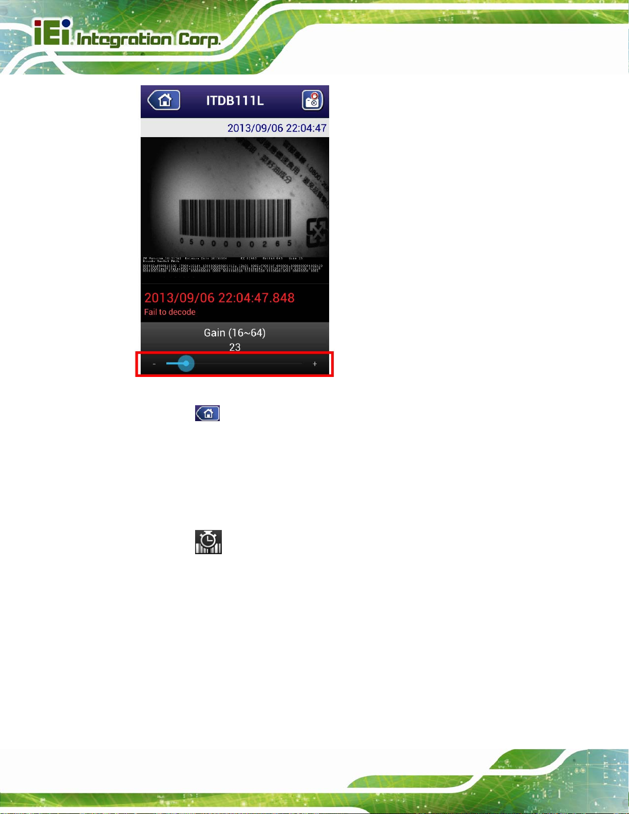
6.5.6.4 Gain Parameter
The (gain) option allows the user to adjust the gain parameter.
Step 1: Tap
adjust the gain parameter.
or the Back key on the Android device to return to the barcode reader
, then drag the slider at the bottom of the screen (Figure 6-8) to
Page 65
Page 75
ITDB-100L Barcode Reader
Figure 6-8: Gain Parameter
Step 2: Tap
list screen. Then the gain parameter will be stored to the barcode reader.
or the Back key on the Android device to return to the barcode reader
6.5.6.5 Decoding Time
The user may need to increase the decoding time when the scanned barcode is
complicated or the reading environment is bad.
Step 1: Tap
adjust the decoding time.
, then drag the slider at the bottom of the screen (Figure 6-9) to
Page 66
Page 76

ITDB-100L Barcode Reader
Figure 6-9: Decoding Time
Step 2: Tap
list screen. Then the decoding time parameter will be stored to the barcode
reader.
or the Back key on the Android device to return to the barcode reader
6.6 Checking the Decoded Images
The parameter values of each captured image are displayed below the image (Figure
6-10).
6.6.1 Checking Captured Images
Follow the steps below to check the captured images stored in the Android device.
Step 1: Tap the All Apps button on the home screen of the Android device.
Step 2: In the application page, find and tap Gallery to launch it.
Page 67
Page 77

Step 3: Tap barcode to display the captured images.
The captured images are stored in /storage/sdcard0/Pictures/barcode of the
Android device.
Step 4: Tap an image to check its parameter values.
The parameter values of each captured image are displayed below the image
Figure 6-10).
(
ITDB-100L Barcode Reader
Figure 6-10: Parameter Values
6.6.2 Sending an Captured Image to IEI
The user might need to report a failed-decoded image to IEI for analyzing. Follow the
steps below to complete the task.
NOTE:
Ensure the captured image to be sent to IEI is stored in Bitmap format.
Page 68
Refer to Section
6.3 to set up the captured image format.
Page 78

ITDB-100L Barcode Reader
Step 1: Repeat Step 1 ~ Step 4 in previous section.
Step 2: Tap the image to bring up the toolbar.
Step 3: Tap Share, then select e-mail to send the selected image to IEI.
Page 69
Page 79

ITDB-100L Barcode Reader
Appendix
A
A Safety Precautions
Page 70
Page 80

ITDB-100L Barcode Reader
A.1 Safety Precautions
WARNING:
The precautions outlined in this appendix should be strictly followed.
Failure to follow these precautions may result in permanent damage to
the ITDB-100L.
Please follow the safety precautions outlined in the sections that follow:
A.1.1 General Safety Precautions
Please ensure the following safety precautions are adhered to at all times.
Make sure the power is turned off and the power cord is disco nnected
when moving, installing or modifying the system.
Do not apply voltage levels that exceed the specified voltage range.
Doing so may cause fire and/or an electrical shock.
Electric shocks can occur if opened while still powered on.
Do not drop or insert any objects into the ventilation openings.
If considerable amounts of dust, water, or fluids enter the system, turn
off the power supply immediately, unplug the power cord, and contact the
system vendor.
DO NOT:
o Drop the system against a hard surface.
o Strike or exert excessive force onto the LCD panel.
o Touch any of the LCD panels with a sharp object
o In a site where the ambient temperature exceeds the rated temperature
Page 71
Page 81

A.1.2 Anti-static Precautions
WARNING:
Failure to take ESD precautions during the installation of the
ITDB-100L may result in permanent damage to the ITDB-100L and
severe injury to the user.
Electrostatic discharge (ESD) can cause serious damage to electronic components,
including the ITDB-100L. Dry climates are especially susceptible to ESD. It is therefore
critical that whenever the ITDB-100L is opened and any of the electrical components are
handled, the following anti-static precautions are strictly adhered to.
Wear an anti-static wristband: Wearing a simple anti-static wristband can
ITDB-100L Barcode Reader
help to prevent ESD from damaging any electrical component.
Self-grounding: Before handling any electrical component, touch any
grounded conducting material. During the time the electrical component is
handled, frequently touch any conducting materials that are connected to the
ground.
Use an anti-static pad: When configuring or working with an electrical
component, place it on an antic-static pad. This reduces the possibility of ESD
damage.
Only handle the edges of the electrical component: When handling the
electrical component, hold the electrical component by its edges.
Page 72
Page 82

ITDB-100L Barcode Reader
A.1.3 Product Disposal
CAUTION:
Risk of explosion if battery is replaced by an incorrect type. Only
certified engineers should replace the on-board battery.
Dispose of used batteries according to instructions and local
regulations.
Outside the European Union - If you wish to dispose of used electrical and
electronic products outside the European Union, please contact your local
authority so as to comply with the correct disposal method.
Within the European Union:
EU-wide legislation, as implemented in each Member State, requires that
waste electrical and electronic products carrying the mark (left) must be
disposed of separately from normal household waste. This includes
monitors and electrical accessories, such as signal cables or power cords.
When you need to dispose of your display products, please follow the
guidance of your local authority, or ask the shop where you purchased the product. The
mark on electrical and electronic products only applies to the current European Union
Member States.
Please follow the national guidelines for electrical and electronic product disposal.
A.2 Maintenance and Cleaning Precautions
When maintaining or cleaning the ITDB-100L, please follow the guidelines below.
A.2.1 Maintenance and Cleaning
Prior to cleaning any part or component of the ITDB-100L, please read the details below.
The interior of the ITDB-100L does not require cleaning. Keep fluids away
from the ITDB-100L interior.
Page 73
Page 83

Be cautious of all small removable components when vacuuming the
ITDB-100L.
Turn the ITDB-100L off before cleaning the ITDB-100L.
Never drop any objects or liquids through the openings of the ITDB-100L.
Be cautious of any possible allergic reactions to solvents or chemicals used
when cleaning the ITDB-100L.
Avoid eating, drinking and smoking within vicinity of the ITDB-100L.
A.2.2 Cleaning Tools
Some components in the ITDB-100L may only be cleaned using a product specifically
designed for the purpose. In such case, the product will be explicitly mentioned in the
cleaning tips. Below is a list of items to use when cleaning the ITDB-100L.
Cloth – Although paper towels or tissues can be used, a soft, clean piece of
ITDB-100L Barcode Reader
cloth is recommended when cleaning the ITDB-100L.
Water or rubbing alcohol – A cloth moistened with water or rubbing alcohol
can be used to clean the ITDB-100L.
Using solvents – The use of solvents is not recommended when cleaning the
ITDB-100L as they may damage the plastic parts.
Vacuum cleaner – Using a vacuum specifically designed for computers is
one of the best methods of cleaning the ITDB-100L. Dust and dirt can restrict
the airflow in the ITDB-100L and cause its circuitry to corrode.
Cotton swabs - Cotton swaps moistened with rubbing alcohol or water are
excellent tools for wiping hard to reach areas.
Foam swabs - Whenever possible, it is best to use lint free swabs such as
foam swabs for cleaning.
Page 74
Page 84

ITDB-100L Barcode Reader
B Hazardous Materials
Appendix
B
Disclosure
Page 75
Page 85

ITDB-100L Barcode Reader
B.1 Hazardous Materials Disclosure Table for IPB Products
Certified as RoHS Compliant Under 2002/95/EC Without
Mercury
The details provided in this appendix are to ensure that the product is compliant with the
Peoples Republic of China (China) RoHS standards. The table below acknowledges the
presences of small quantities of certain materials in the product, and is applicable to China
RoHS only.
A label will be placed on each product to indicate the estimated “Environmentally Friendly
Use Period” (EFUP). This is an estimate of the number of years that these substances
would “not leak out or undergo abrupt change.” This product may contain replaceable
sub-assemblies/components which have a shorter EFUP such as batteries and lamps.
These components will be separately marked.
Please refer to the table on the next page.
Page 76
Page 86

ITDB-100L Barcode Reader
Toxic or Hazardous Substances and Elements Part Name
Housing
Display
Printed Circuit
Board
Metal
Fasteners
Cable
Assembly
Fan Assembly
Power Supply
Assemblies
Lead
(Pb)
O O O O O O
O O O O O O
O O O O O O
O O O O O O
O O O O O O
O O O O O O
O O O O O O
Mercury
(Hg)
Cadmium
(Cd)
Hexavalent
Chromium
(CR(VI))
Polybrominated
Biphenyls
(PBB)
Polybrominated
Diphenyl
Ethers
(PBDE)
Battery
O: This toxic or hazardous substance is contained in all of the homogeneous materials for the part is
below the limit requirement in SJ/T11363-2006
X: This toxic or hazardous substance is contained in at least one of the homogeneous materials for
this part is above the limit requirement in SJ/T11363-2006
O O O O O O
Page 77
Page 87

此附件旨在确保本产品符合中国 RoHS 标准。以下表格标示此产品中某有毒物质的含量符
合中国 RoHS 标准规定的限量要求。
本产品上会附有”环境友好使用期限”的标签,此期限是估算这些物质”不会有泄漏或突变”的
年限。本产品可能包含有较短的环境友好使用期限的可替换元件,像是电池或灯管,这些元
件将会单独标示出来。
ITDB-100L Barcode Reader
部件名称
壳体
显示
印刷电路板
金属螺帽
电缆组装
风扇组装
电力供应组装
电池
O: 表示该有毒有害物质在该部件所有物质材料中的含量均在 SJ/T11363-2006 标准规定的限量要求以下。
X: 表示该有毒有害物质至少在该部件的某一均质材料中的含量超出 SJ/T11363-2006 标准规定的限量要求。
有毒有害物质或元素
铅
(Pb)
O O O O O O
O O O O O O
O O O O O O
O O O O O O
O O O O O O
O O O O O O
O O O O O O
O O O O O O
汞
(Hg)
镉
(Cd)
六价铬
(CR(VI))
多溴联苯
(PBB)
多溴二苯
醚
(PBDE)
Page 78
 Loading...