

Page 1
IOWA-LX-600 Half-size CPU Card
)zIOWA-LX-600 CPU Card
IEI Technology Corp.
MODEL:
IOWA-LX-600
Half-size ISA CPU Card with on-board AMD Geode LX 600
VGA, LAN, USB 2.0, CF, COM, Parallel Port and Audio
RoHS Compliant
User Manual
Rev. 1.00 - 31 March, 2011
Page I
Page 2
Date Version Changes
31 March, 2011 1.00 Initial release
IOWA-LX-600 Half-size CPU Card
Revision
Page II
Page 3

IOWA-LX-600 Half-size CPU Card
COPYRIGHT NOTICE
The information in this document is subject to change without prior notice in order to
improve reliability, design and function and does not represent a commitment on the part
of the manufacturer.
In no event will the manufacturer be liable for direct, indirect, special, incidental, or
consequential damages arising out of the use or inability to use the product or
documentation, even if advised of the possibility of such damages.
This document contains proprietary information protected by copyright. All rights are
Copyright
reserved. No part of this manual may be reproduced by any mechanical, electronic, or
other means in any form without prior written permission of the manufacturer.
TRADEMARKS
All registered trademarks and product names mentioned herein are used for identification
purposes only and may be trademarks and/or registered trademarks of their respective
owners.
Page III
Page 4

IOWA-LX-600 Half-size CPU Card
Table of Contents
1 INTRODUCTION.......................................................................................................... 1
1.1 INTRODUCTION........................................................................................................... 2
1.2 MODEL VARIATIONS ................................................................................................... 2
1.3 BENEFITS ................................................................................................................... 3
1.4 FEATURES................................................................................................................... 3
1.5 CONNECTORS ............................................................................................................. 4
1.6 DIMENSIONS............................................................................................................... 5
1.7 DATA FLOW................................................................................................................ 6
1.8 TECHNICAL SPECIFICATIONS ...................................................................................... 7
2 UNPACKING................................................................................................................. 9
2.1 ANTI-STATIC PRECAUTIONS...................................................................................... 10
2.2 UNPACKING PRECAUTIONS....................................................................................... 10
2.3 PACKING LIST............................................................................................................11
2.3.1 Optional Items.................................................................................................. 12
3 CONNECTORS ........................................................................................................... 13
3.1 PERIPHERAL INTERFACE CONNECTORS..................................................................... 14
3.1.1 IOWA-LX-600 Layout ...................................................................................... 14
3.1.2 Peripheral Interface Connectors ..................................................................... 15
3.1.3 External Interface Panel Connectors............................................................... 16
3.2 INTERNAL PERIPHERAL CONNECTORS ...................................................................... 16
3.2.1 ATX Power Enable Connector......................................................................... 16
3.2.2 Audio Connector (10-pin)................................................................................ 17
3.2.3 Backlight Inverter Connector .......................................................................... 18
3.2.4 Battery Connector............................................................................................ 19
3.2.5 CompactFlash® Socket.................................................................................... 20
3.2.6 Digital Input/Output (DIO) Connector............................................................ 22
3.2.7 Fan Connector (+5V) ...................................................................................... 23
3.2.8 Floppy Disk Connector.................................................................................... 24
3.2.9 Front Panel Connector (8-pin)........................................................................ 25
Page IV
Page 5

IOWA-LX-600 Half-size CPU Card
3.2.10 IDE Connector (40-pin)................................................................................. 26
3.2.11 Infrared Interface Connector (5-pin)............................................................. 27
3.2.12 Keyboard/Mouse Connector.......................................................................... 28
3.2.13 Parallel Port Connector ................................................................................ 29
3.2.14 Power Connector........................................................................................... 30
3.2.15 SATA Drive Connectors (Optional)................................................................ 31
3.2.16 Serial Port Connector (RS-232/422/485) ...................................................... 32
3.2.17 TTL Connector............................................................................................... 33
3.2.18 Internal USB Connectors............................................................................... 35
3.2.19 -VCC Power Connector................................................................................. 36
3.3 EXTERNAL PERIPHERAL INTERFACE CONNECTORS................................................... 37
3.3.1 PS/2 Keyboard/Mouse Connector.................................................................... 37
3.3.2 RJ-45 Ethernet Connector ............................................................................... 38
3.3.3 Serial Port Connector (COM 1) ...................................................................... 39
3.3.4 VGA Connector................................................................................................ 40
4 INSTALLATION ......................................................................................................... 41
4.1 ANTI-STATIC PRECAUTIONS...................................................................................... 42
4.2 INSTALLATION CONSIDERATIONS.............................................................................. 43
4.2.1 Installation Notices.......................................................................................... 43
4.3 UNPACKING.............................................................................................................. 44
4.4 SO-DIMM INSTALLATION ....................................................................................... 44
4.5 CF CARD INSTALLATION .......................................................................................... 45
4.6 JUMPER SETTINGS .................................................................................................... 47
4.6.1 AT/ATX Power Select....................................................................................... 47
4.6.2 CF Card Setup ................................................................................................. 48
4.6.3 COM 3 Function Select.................................................................................... 49
4.6.4 LCD Voltage Select.......................................................................................... 50
4.6.5 LCD Clock Select Jumper................................................................................ 51
4.7 CHASSIS INSTALLATION............................................................................................ 52
4.7.1 Airflow.............................................................................................................. 52
4.7.2 Backplane Installation..................................................................................... 52
4.7.3 CPU Card Installation..................................................................................... 52
4.8 INTERNAL PERIPHERAL DEVICE CONNECTIONS........................................................ 53
4.8.1 5.1 Channel Audio Kit Installation.................................................................. 53
Page V
Page 6

4.8.2 ATA Flat Cable Connection ............................................................................. 54
4.8.3 USB Cable........................................................................................................ 55
4.9 EXTERNAL PERIPHERAL INTERFACE CONNECTION................................................... 56
4.9.1 LAN Connection (Single Connector)............................................................... 56
4.9.2 PS/2 Y-Cable Connection................................................................................. 57
4.9.3 Serial Device Connection ................................................................................ 58
4.9.4 VGA Monitor Connection ................................................................................ 59
4.10 SOFTWARE INSTALLATION ...................................................................................... 60
5 BIOS SCREENS........................................................................................................... 62
5.1 INTRODUCTION......................................................................................................... 63
5.1.1 Starting Setup................................................................................................... 63
5.1.2 Using Setup...................................................................................................... 63
5.1.3 Getting Help..................................................................................................... 64
5.1.4 Unable to Reboot After Configuration Changes.............................................. 64
IOWA-LX-600 Half-size CPU Card
5.1.5 Main BIOS Menu ............................................................................................. 64
5.2 STANDARD BIOS FEATURES .................................................................................... 66
5.2.1 IDE Primary Master/Slave .............................................................................. 68
5.3 ADVANCED BIOS FEATURES.................................................................................... 71
5.4 ADVANCED CHIPSET FEATURES................................................................................ 79
5.4.1 Flat Panel Configuration................................................................................. 81
5.5 INTEGRATED PERIPHERALS....................................................................................... 84
5.5.1 IT8888 ISA Decode IO..................................................................................... 90
5.5.2 IT8888 ISA Decode Memory............................................................................ 92
5.6 POWER MANAGEMENT SETUP.................................................................................. 94
5.7 PNP/PCI CONFIGURATIONS...................................................................................... 97
5.8 HEALTH STATUS ..................................................................................................... 100
A BIOS MENU OPTIONS........................................................................................... 102
B ONE KEY RECOVERY........................................................................................... 106
B.1 ONE KEY RECOVERY INTRODUCTION .................................................................... 107
B.1.1 System Requirement....................................................................................... 108
B.1.2 Supported Operating System......................................................................... 109
B.2 SETUP PROCEDURE FOR WINDOWS.........................................................................110
B.2.1 Hardware and BIOS Setup .............................................................................110
Page VI
Page 7

IOWA-LX-600 Half-size CPU Card
B.2.2 Create Partitions............................................................................................111
B.2.3 Install Operating System, Drivers and Applications......................................114
B.2.4 Build-up Recovery Partition...........................................................................115
B.2.5 Create Factory Default Image........................................................................117
B.3 SETUP PROCEDURE FOR LINUX.............................................................................. 122
B.4 RECOVERY TOOL FUNCTIONS ................................................................................ 125
B.4.1 Factory Restore............................................................................................. 127
B.4.2 Backup System............................................................................................... 128
B.4.3 Restore Your Last Backup.............................................................................. 129
B.4.4 Manual........................................................................................................... 130
B.5 OTHER INFORMATION............................................................................................ 131
B.5.1 Using AHCI Mode or ALi M5283 / VIA VT6421A Controller....................... 131
B.5.2 System Memory Requirement ........................................................................ 133
C TERMINOLOGY ..................................................................................................... 134
D WATCHDOG TIMER .............................................................................................. 139
E HAZARDOUS MATERIALS DISCLOSURE ....................................................... 142
E.1 HAZARDOUS MATERIAL DISCLOSURE TABLE FOR IPB PRODUCTS CER TIFIED AS
ROHS COMPLIANT UNDER 2002/95/EC WITHOUT MERCURY ..................................... 143
Page VII
Page 8

IOWA-LX-600 Half-size CPU Card
List of Figures
Figure 1-1: IOWA-LX-600 ...............................................................................................................2
Figure 1-2: Connectors ..................................................................................................................4
Figure 1-3: IOWA-LX-600 Dimensions (mm)................................................................................5
Figure 1-4: Data Flow Block Diagram...........................................................................................6
Figure 3-1: Connector and Jumper Locations...........................................................................14
Figure 3-2: ATX Power Supply Enable Connector Location....................................................17
Figure 3-3: Audio Connector Pinouts (10-pin)...........................................................................18
Figure 3-4: Backlight Inverter Connector Pinout Locations ....................................................19
Figure 3-5: Battery Connector Location.....................................................................................20
Figure 3-6: CF Card Socket Location .........................................................................................21
Figure 3-7: DIO Connector Locations.........................................................................................22
Figure 3-8: Fan Connector Location...........................................................................................23
Figure 3-9: FDD Connector Location..........................................................................................24
Figure 3-10: Front Panel Connector Pinout Locations.............................................................25
Figure 3-11: IDE Device Connector Locations ..........................................................................26
Figure 3-12: Infrared Connector Pinout Locations ...................................................................28
Figure 3-13: Keyboard/Mouse Connector Location..................................................................29
Figure 3-14: Parallel Port Connector Location..........................................................................30
Figure 3-15: Power Connector Location ....................................................................................31
Figure 3-16: SATA Drive Connector Locations.........................................................................32
Figure 3-17: Internal Serial Port Connector Pinout Locations.................................................33
Figure 3-18: TFT LCD Connector Pinout Locations..................................................................34
Figure 3-19: USB Connector Pinout Locations.........................................................................35
Figure 3-20: -VCC Power Connector Pinout Locations............................................................36
Figure 3-21: IOWA-LX-600 On-board External Interface Connectors......................................37
Figure 3-22: PS/2 Pinouts............................................................................................................37
Figure 3-23: RJ-45 Connector .....................................................................................................39
Figure 3-24: COM1 Pinout Locations..........................................................................................40
Figure 4-1: SO-DIMM Installation................................................................................................45
Figure 4-2: CF Card Installation..................................................................................................46
Figure 4-3: Jumper Locations.....................................................................................................47
Page VIII
Page 9

IOWA-LX-600 Half-size CPU Card
Figure 4-4: AT/ATX Power Select Jumper Location..................................................................48
Figure 4-5: CompactFlash® Setup Jumper Location ...............................................................49
Figure 4-6: COM 3 Function Select Jumper Location...............................................................50
Figure 4-7: LVDS Voltage Selection Jumper Locations ...........................................................51
Figure 4-8: LCD Clock Select Jumper Location........................................................................51
Figure 4-9: 5.1 Channel Audio Kit...............................................................................................53
Figure 4-10: IDE Cable Connection.............................................................................................54
Figure 4-11: Dual USB Cable Connection..................................................................................55
Figure 4-12: LAN Connection......................................................................................................56
Figure 4-13: PS/2 Keyboard/Mouse Connector.........................................................................57
Figure 4-14: Serial Device Connector.........................................................................................58
Figure 4-15: VGA Connector .......................................................................................................59
Figure 4-16: Introduction Screen................................................................................................60
Figure 4-17: Available Drivers.....................................................................................................61
Figure B-1: IEI One Key Recovery Tool Menu........................................................................ 107
Figure B-2: Launching the Recovery Tool.............................................................................. 111
Figure B-3: Recovery Tool Setup Menu .................................................................................. 112
Figure B-4: Command Mode..................................................................................................... 112
Figure B-5: Partition Creation Commands.............................................................................. 113
Figure B-6: Launching the Recovery Tool.............................................................................. 115
Figure B-7: System Configuration for Windows .................................................................... 115
Figure B-8: Build-up Recovery Partition................................................................................. 116
Figure B-9: Press any key to continue.................................................................................... 116
Figure B-10: Press F3 to Boot into Recovery Mode............................................................... 117
Figure B-11: Recovery Tool Menu ........................................................................................... 117
Figure B-12: About Symantec Ghost Window........................................................................ 118
Figure B-13: Symantec Ghost Path ......................................................................................... 118
Figure B-14: Select a Local Source Drive ............................................................................... 119
Figure B-15: Select a Source Partition from Basic Drive ...................................................... 119
Figure B-16: File Name to Copy Image to ............................................................................... 120
Figure B-17: Compress Image.................................................................................................. 120
Figure B-18: Image Creation Confirmation............................................................................. 121
Figure B-19: Image Creation Process...................................................................................... 121
Figure B-20: Image Creation Complete................................................................................... 121
Figure B-21: Press Any Key to Continue................................................................................ 122
Page IX
Page 10

Figure B-22: Partitions for Linux.............................................................................................. 123
Figure B-23: System Configuration for Linux......................................................................... 124
Figure B-24: Access menu.lst in Linux (Text Mode).............................................................. 124
Figure B-25: Recovery Tool Menu ........................................................................................... 125
Figure B-26: Recovery Tool Main Menu.................................................................................. 126
Figure B-27: Restore Factory Default...................................................................................... 127
Figure B-28: Recovery Complete Window.............................................................................. 127
Figure B-29: Backup System.................................................................................................... 128
Figure B-30: System Backup Complete Window ................................................................... 128
Figure B-31: Restore Backup................................................................................................... 129
Figure B-32: Restore System Backup Complete Window..................................................... 129
Figure B-33: Symantec Ghost Window ................................................................................... 130
IOWA-LX-600 Half-size CPU Card
Page X
Page 11
IOWA-LX-600 Half-size CPU Card
List of Tables
Table 1-1: IOWA-LX-600 Model Variations...................................................................................3
Table 1-2: Technical Specifications..............................................................................................8
Table 3-1: Peripheral Interface Connectors...............................................................................16
Table 3-2: Rear Panel Connectors..............................................................................................16
Table 3-3: ATX Power Supply Enable Connector Pinouts .......................................................17
Table 3-4: Audio Connector Pinouts (10-pin)............................................................................18
Table 3-5: Backlight Inverter Connector Pinouts......................................................................19
Table 3-6: Battery Connector Pinouts........................................................................................20
Table 3-7: CF Card Socket Pinouts.............................................................................................22
Table 3-8: DIO Connector Pinouts..............................................................................................23
Table 3-9: Fan Connector Pinouts..............................................................................................23
Table 3-10: FDD Connector Pinouts...........................................................................................25
Table 3-11: Front Panel Connector Pinouts...............................................................................26
Table 3-12: IDE Connector Pinouts.............................................................................................27
Table 3-13: Infrared Connector Pinouts.....................................................................................28
Table 3-14: Keyboard/Mouse Connector Pinouts .....................................................................29
Table 3-15: Parallel Port Connector Pinouts .............................................................................30
Table 3-16: Power Connector Pinouts........................................................................................31
Table 3-17: SATA Drive Connector Pinouts...............................................................................32
Table 3-18: Internal Serial Port Connector Pinouts ..................................................................33
Table 3-19: TFT LCD Port Connector Pinouts ...........................................................................34
Table 3-20: USB Port Connector Pinouts...................................................................................35
Table 3-21: -VCC Power Connector Pinouts..............................................................................36
Table 3-22: PS/2 Connector Pinouts...........................................................................................38
Table 3-23: RJ-45 Ethernet Connector Pinouts.........................................................................38
Table 3-24: J7 Connector LEDs...................................................................................................39
Table 3-25: RS-232 Serial Port (COM 1) Pinouts .......................................................................39
Table 3-26: VGA Connector Pinouts...........................................................................................40
Table 4-1: Jumpers.......................................................................................................................47
Table 4-2: AT/ATX Power Select Jumper Settings....................................................................48
Table 4-3: CompactFlash® Setup Jumper Settings..................................................................49
Page XI
Page 12

Table 4-4: COM 3 Function Select Jumper Settings.................................................................49
Table 4-5: LVDS Voltage Selection Jumper Settings................................................................50
Table 4-6: LCD Clock Select Jumper Settings...........................................................................51
Table 5-1: BIOS Navigation Keys................................................................................................64
IOWA-LX-600 Half-size CPU Card
Page XII
Page 13

IOWA-LX-600 Half-size CPU Card
List of BIOS Menus
BIOS Menu 1: Award BIOS Setup Utility ....................................................................................64
BIOS Menu 2: Standard CMOS Features....................................................................................67
BIOS Menu 3: IDE Channel Master..............................................................................................69
BIOS Menu 4: IDE Channel Master..............................................................................................71
BIOS Menu 5: Advanced Chipset Features................................................................................79
BIOS Menu 6: Flat Panel Configuration......................................................................................82
BIOS Menu 7: Integrated Peripherals.........................................................................................85
BIOS Menu 8: IT8888 ISA Decode IO..........................................................................................91
BIOS Menu 9: IT8888 ISA Decode Memory................................................................................93
BIOS Menu 10: Power Management Setup ................................................................................95
BIOS Menu 11: PnP/PCI Configurations.....................................................................................97
BIOS Menu 12: PC Health Status............................................................................................. 100
Page XIII
Page 14

Page 15
IOWA-LX-600 Half-size CPU Card
Chapter
1
1 Introduction
Page 1
Page 16
1.1 Introduction
IOWA-LX-600 Half-size CPU Card
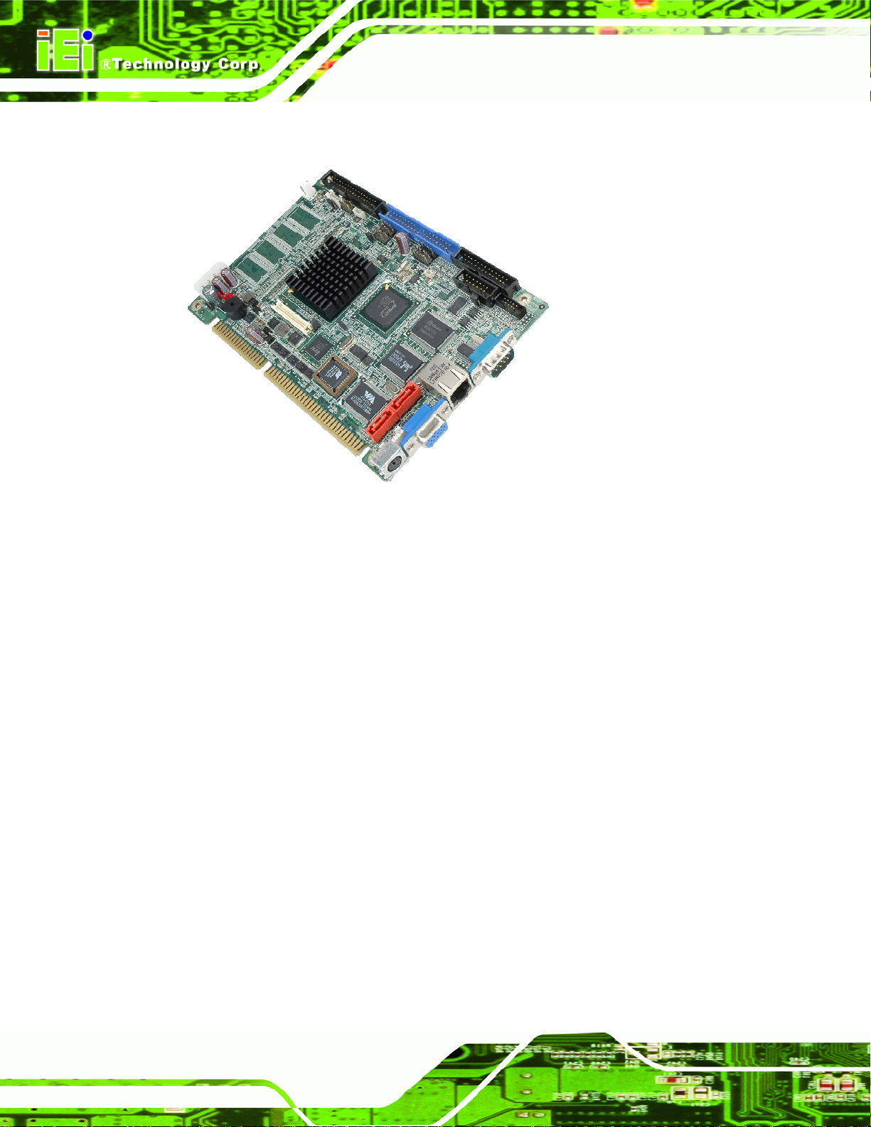
Figure 1-1: IOWA-LX-600
The IOWA-LX-600 is an AMD Geode™ LX based based half-size ISA CPU card. The
IOWA-LX-600 has a Front Side Bus (FSB) of 366 MHz, 128 MB of RAM on-board and is
upgradeable with a further 512 MB of SDRAM.
Multiple input/output options include VGA and 24-bit TTL for video output, a parallel port,
two serial ports, an infrared port and 10/100BASE-T Ethernet. The IOWA -LX-600 support s
up to two IDE drives and one floppy drive. Two SATA ports with RAID 0 and RAID 1
capabilities are optional.
1.2 Model Variations
The IOWA-LX-600 series has two models:
IOWA-LX-600-R10
IOWA-LX-600S-R10
Page 2
The specifications for the two models are show in
5Table 1-1
Page 17

IOWA-LX-600 Half-size CPU Card
MODEL IOWA-LX-600 IOWA-LX-600S
CPU Speed 366 MHz 366 MHz
Onboard Memory 128 MB 128 MB
SATA No Yes
Table 1-1: IOWA-LX-600 Model Variations
1.3 Benefits
Some of the IOWA-LX-600 benefits:
Power efficient, fanless CPU lowers hardware and operational overhead
costs
ISA exp ansion options available through compatible IEI backplanes
Support for both legacy ISA and DMA (direct memory access)
Multiple display output devices including VGA and TTL
RAID options including RAID 1 for increased data saf ety and RAID 0 for
1.4 Features
Some of the IOWA-LX-600 features:
Half-size form factor
RoHS compliant
AMD Geode LX processor installed
VGA or TTL display
Low power consumption
One 10/100BASE-T Ethernet controller on-board
Two SATA channels with transfe r rates up to 1.5Gb/s on-board (SATA model)
Four USB 2.0 devices supported
Integrated audio
improved drive performance for faster data access (on SATA models)
Page 3
Page 18
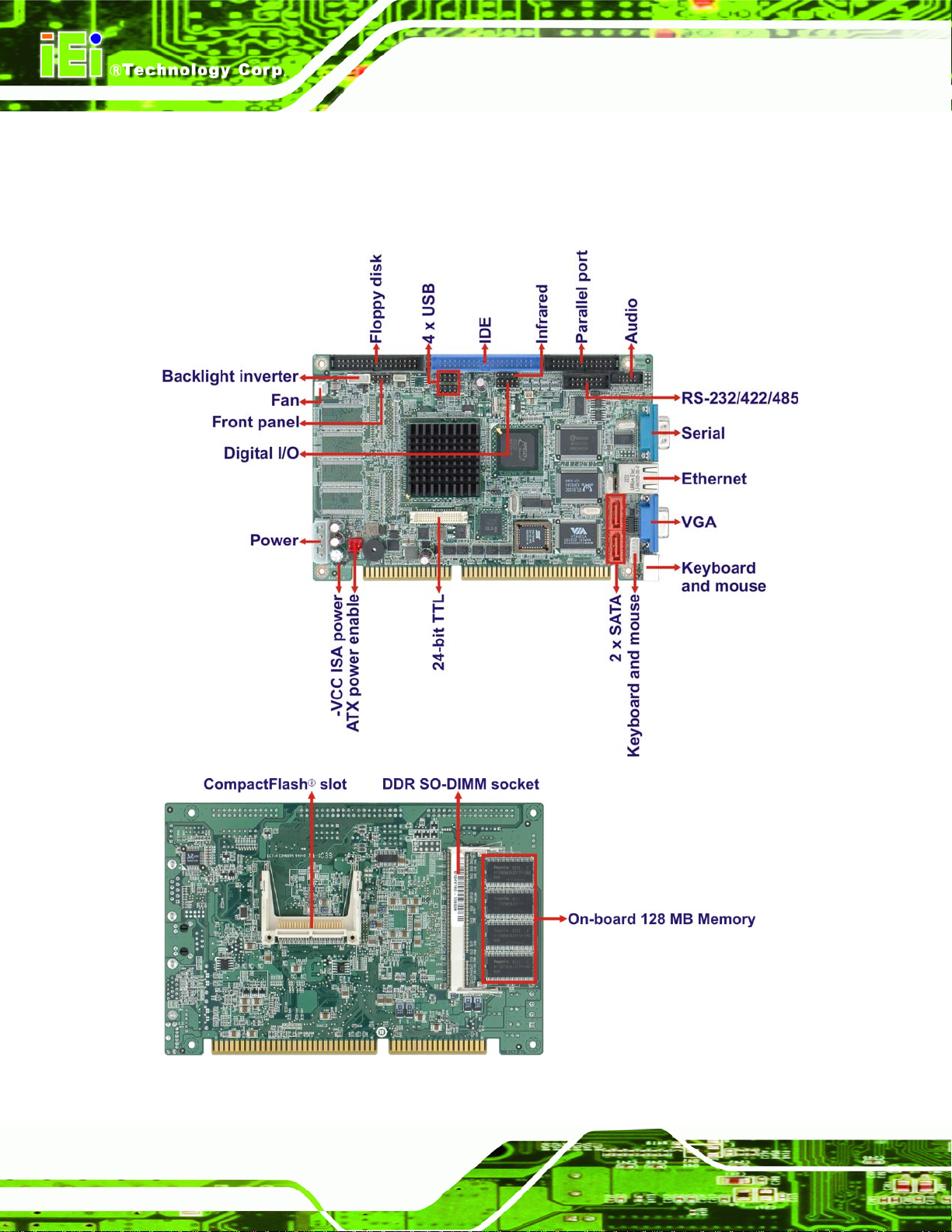
1.5 Connectors
The connectors on the IOWA-LX-600 are shown in the figure below.
IOWA-LX-600 Half-size CPU Card
Figure 1-2: Connectors
Page 4
Page 19
IOWA-LX-600 Half-size CPU Card
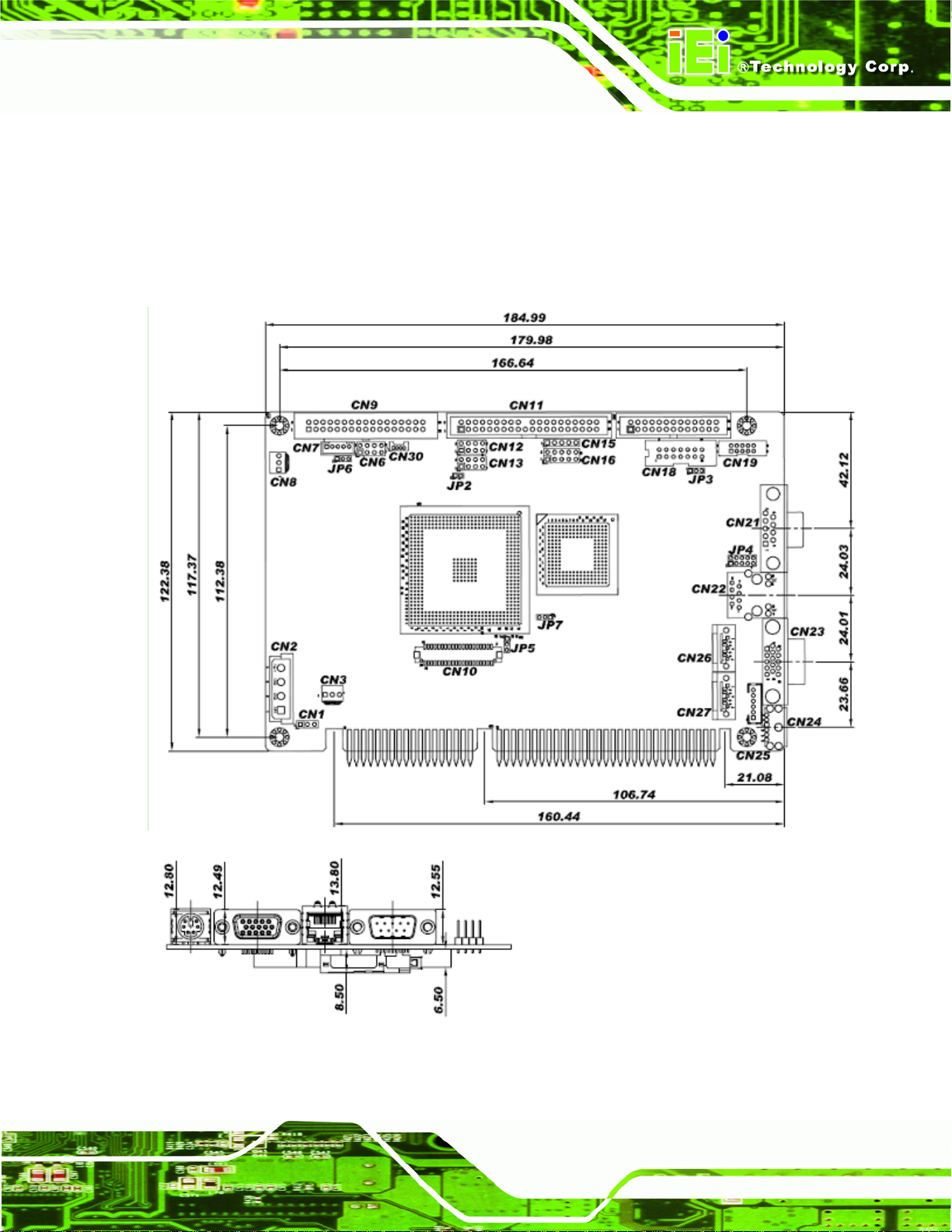
1.6 Dimensions
The dimensions of the board are listed below:
Length: 184.99 mm
Width: 122.38 mm
Figure 1-3: IOWA-LX-600 Dimensions (mm)
Page 5
Page 20
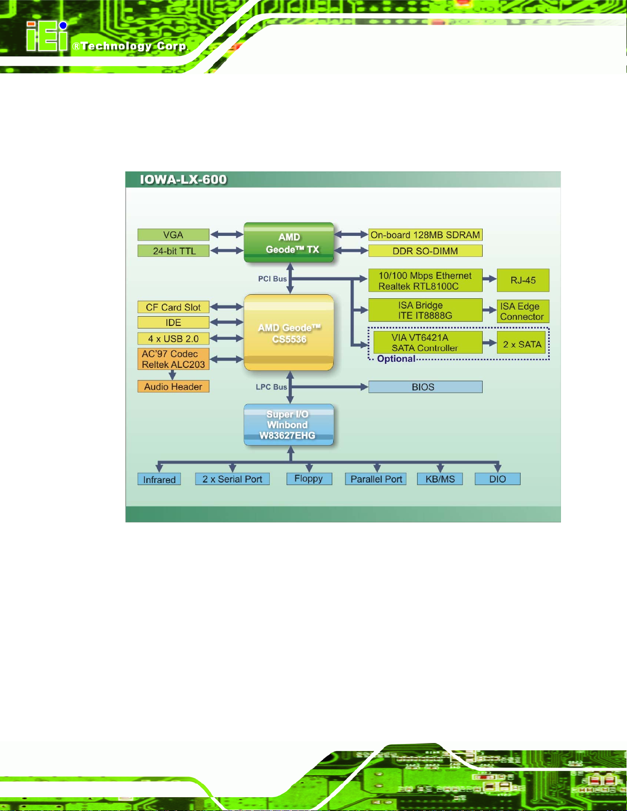
1.7 Data Flow
55Figure 1-4 shows the data flow between the two on-board chipsets and other components
installed on the motherboard and described in the following sections of this chapter.
IOWA-LX-600 Half-size CPU Card
Page 6
Figure 1-4: Data Flow Block Diagram
Page 21
IOWA-LX-600 Half-size CPU Card
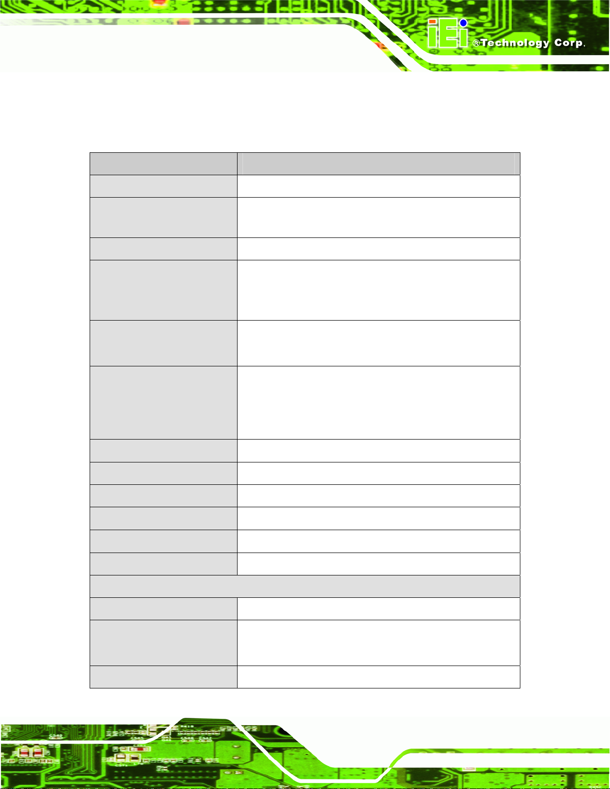
1.8 Technical Specifications
IOWA-LX-600 technical specifications are listed in table below.
Specification IOWA-LX-600
Form Factor
CPU Supported
Express Chipset
Memory
Graphics
Display Output
Audio
LAN
Half-size
AMD Geode LX 600 with a 366 MHz FSB and 128KB L2
cache
AMD Geode CS5536
On-board 128 MB 200/266 MHz DDR SDRAM
One 200-pin SO-DIMM sockets support 200/266 MHz DDR
SDRAM SO-DIMMs (system max. 512 MB)
VGA integrated in AMD Geode™ LX 600
AMD Geode™ LX 600 24-bit TTL
Single HD VOP 2.0 output
1920x1440 CRT output
1600x1200 TFT output
Realtek ALC203 AC’97 audio codec
10/100 Mbps Realtek RTL8100C Ethernet Chipset
Super I/O
BIOS
Digital I/O
Watchdog Timer
I/O Interface Connectors
Audio Connector
Display Ports
Ethernet
Winbond W83627EHG
Award BIOS
8-bit digital I/O (4-bit input/4-bit output)
Software programmable supports 1~2 55 sec. system reset
One internal audio connector (10-pin header)
One external VGA port
One internal 24-bit TTL connector (40-pin)
One RJ-45 10/100 Mbps Ethernet port
Page 7
Page 22
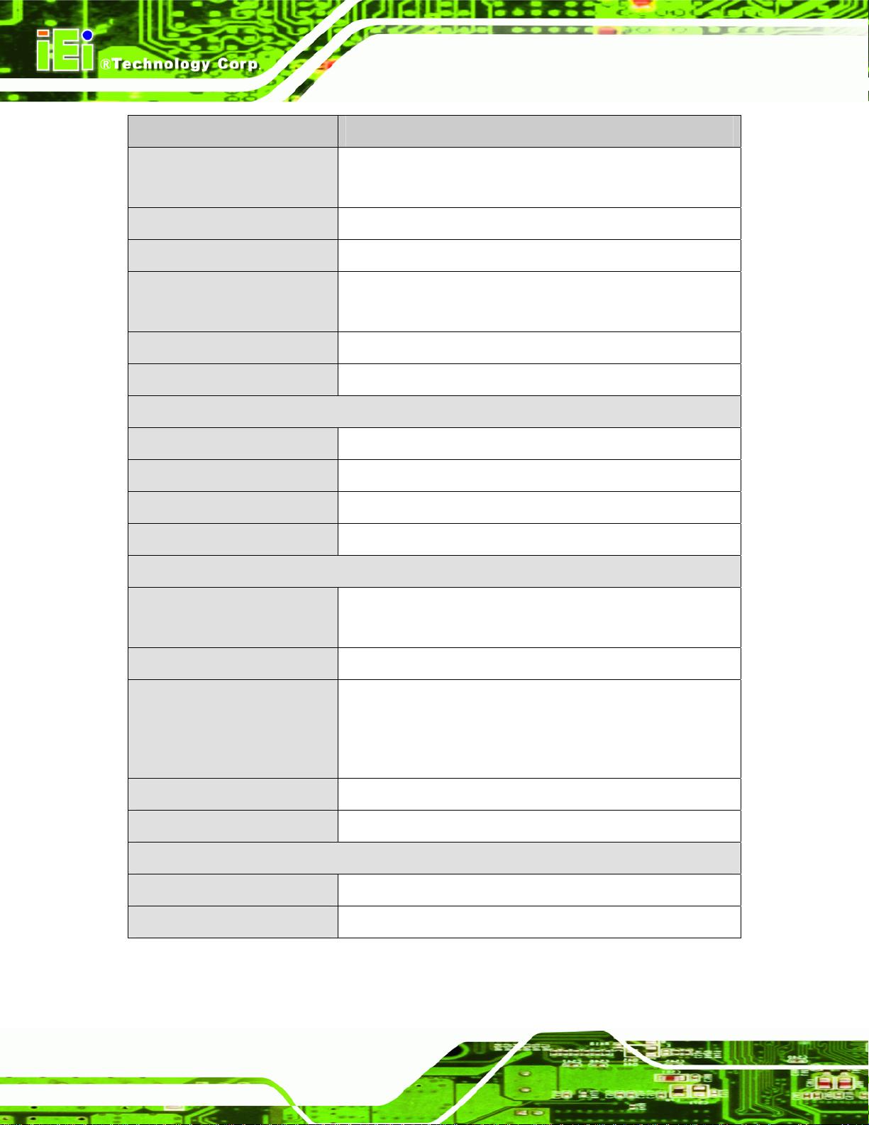
Specification IOWA-LX-600
IOWA-LX-600 Half-size CPU Card
Serial Ports
USB 2.0/1.1 Ports
Parallel Port
Keyboard/Mouse
Fan Connectors
Infrared
Storage
IDE
CompactFlash®
Floppy Disk Drive
Serial ATA (Optional)
Environmental and Power Specifications
Two RS-232
One RS-422/485 via pin header
Four internal USB ports via two 8-pin headers
One internal parallel port via one 26-pin header
One keyboard/mouse connector via one 6-pin wafer
One PS/2 keyboard/mouse connector
One 3-pin fan connector
One 5-pin header
One 40-pin IDE connector
One CF Type II slot
One 34-pin FDD connector
Two SATA 1.5 Gb/s connectors support RAID0, 1
Power Supply
Power Connector
Power Consumption
Operating Temperature
Humidity
Physical Specifications
Dimensions
Weight GW/NW
Table 1-2: Technical Specifications
5 V / 12 V via ISA bus
ATX and AT power supported
One internal 4-pin Molex power connector for power supply
5V@1.51A, 5VSB@0.09A (366 M H z AMD Geode™ LX 600
CPU with on-board 128 MB memory and 512 MB 333 MHz
DDR SDRAM)
-10ºC ~ 60ºC (requires cooler and silicone heat sink paste)
5% ~ 95% (non-condensing)
185.00 mm x 122.38 mm
1000 g / 250 g
Page 8
Page 23

IOWA-LX-600 Half-size CPU Card
Chapter
2
2 Unpacking
Page 9
Page 24
2.1 Anti-static Precautions
WARNING!
Static electricity can destroy certain electronics. Make sure to follow the
ESD precautions to prevent damage to the product, and injury to the
user.
Make sure to adhere to the following guidelines:
Wear an anti-static wristband: Wearing an anti-static wristband can prevent
electrostatic discharge.
Self-grounding: Touch a grounded conductor every fe w minutes to discha rge
any excess static buildup.
IOWA-LX-600 Half-size CPU Card
Use an anti-static pad: When configuring any circuit board, place it on an
anti-static mat.
Only handle the edges of the PCB: Don't touch the surface of the
motherboard. Hold the motherboard by the edges when handling.
2.2 Unpacking Precautions
When the IOWA-LX-600 is unpacked, please do the following:
Follow the antistatic guidelines above.
Make sure the packing box is facing upwards whe n opening.
Make sure all the packing list items are present.
Page 10
Page 25
IOWA-LX-600 Half-size CPU Card
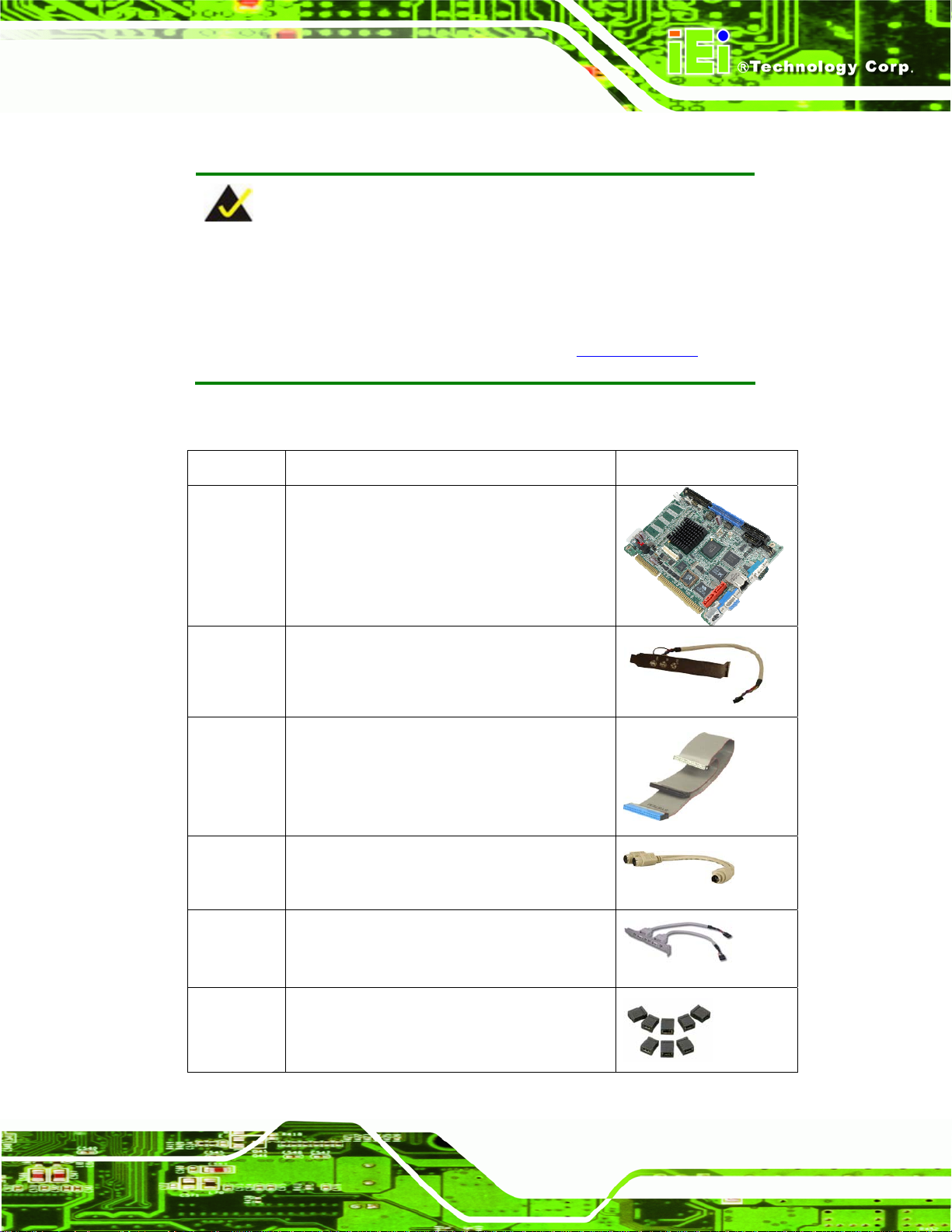
2.3 Packing List
NOTE:
If any of the components listed in the checklist below are missing, do
not proceed with the installation. Contact the IEI reseller or vendor the
IOWA-LX-600 was purchased from or contact an IEI sales
representative directly by sending an email to
The IOWA-LX-600 is shipped with the following components:
Quantity Item and Part Number Image
1 IOWA-LX-600 motherboard
1 Audio cable
(P/N: 19800-000111-RS)
1 IDE flat cable
(P/N: 32200-000052-RS)
322sales@iei.com.tw.
1 KB/MS PS/2 Y-cable
(P/N: 32006-000300-100-RS)
1 Dual USB cable (w bracket)
(P/N: CB-USB02-RS)
1 Mini jumper pack (2.0mm)
(P/N: 33100-000033-RS)
Page 11
Page 26
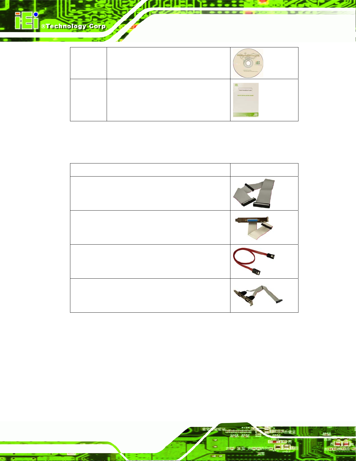
1 Utility CD
1 Quick Installation Guide
2.3.1 Optional Items
The following are optional components which may be separately purchased:
Item and Part Number Image
FDD cable
(P/N: 32200-000017-RS)
IOWA-LX-600 Half-size CPU Card
Parallel port cable
(P/N:19800-000400-100-RS)
SATA cable
(P/N: 32000-062800-RS)
Dual RS-232/422/485 cable
(P/N: 19800-000058-RS)
Page 12
Page 27

IOWA-LX-600 Half-size CPU Card
Chapter
3
3 Connectors
Page 13
Page 28
3.1 Peripheral Interface Connectors
This chapter details all the jumpers and connectors.
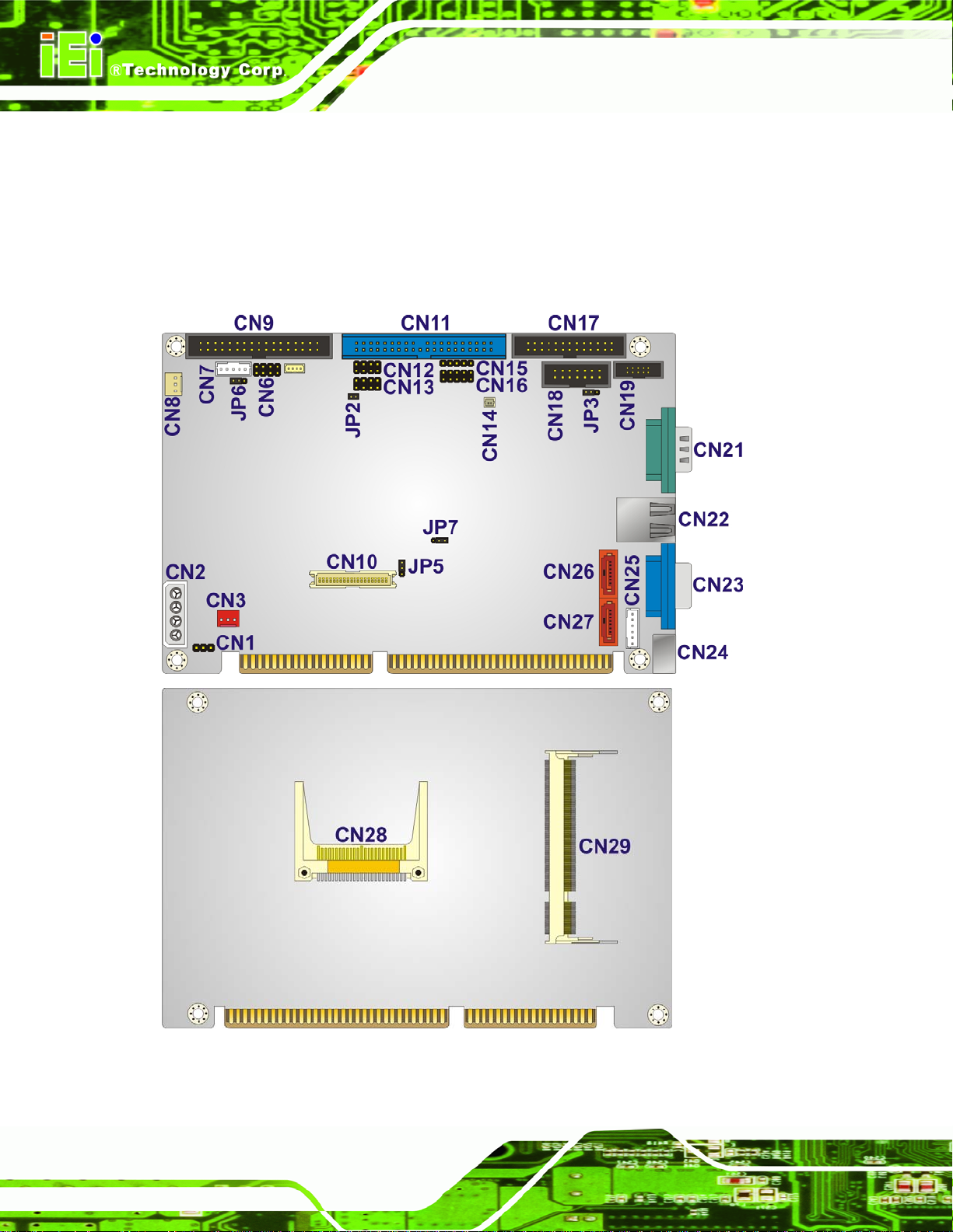
3.1.1 IOWA-LX-600 Layout
The figures below show all the connectors and jumpers.
IOWA-LX-600 Half-size CPU Card
Figure 3-1: Connector and Jumper Locations
Page 14
Page 29
IOWA-LX-600 Half-size CPU Card
3.1.2 Peripheral Interface Connectors
The table below lists all the connectors on the board.
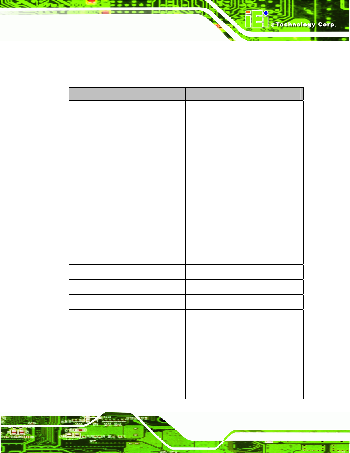
Connector Type Label
ATX power enable connector 3-pin wafer CN3
Audio connector 10-pin box header CN19
Backlight inverter connector 5-pin wafer CN7
Battery connector 2-pin wafer CN14
CompactFlash® slot CF Type II slot CN28
DDR SO-DIMM socket 200-pin socket CN29
Digital I/O connector 10-pin header CN16
Fan connector (CPU) 3-pin wafer CN8
Floppy disk connector 34-pin box header CN9
Front panel connector 10-pin header CN6
IDE connector 40-pin box header CN11
Infrared connector 5-pin header CN15
Keyboard and mouse connector 6-pin wafer CN25
Parallel port connector 26-pin box header CN17
Power connector (+12V, power supply) 4-pin connector CN2
RS-232/422/485 serial port connector 14-pin box header CN18
Serial ATA (SATA) drive connector 7-pin SATA CN26
Serial ATA (SATA) drive connector 7-pin SATA CN27
TTL LCD connector 40-pin crimp CN10
USB connector 8-pin header CN12
Page 15
Page 30
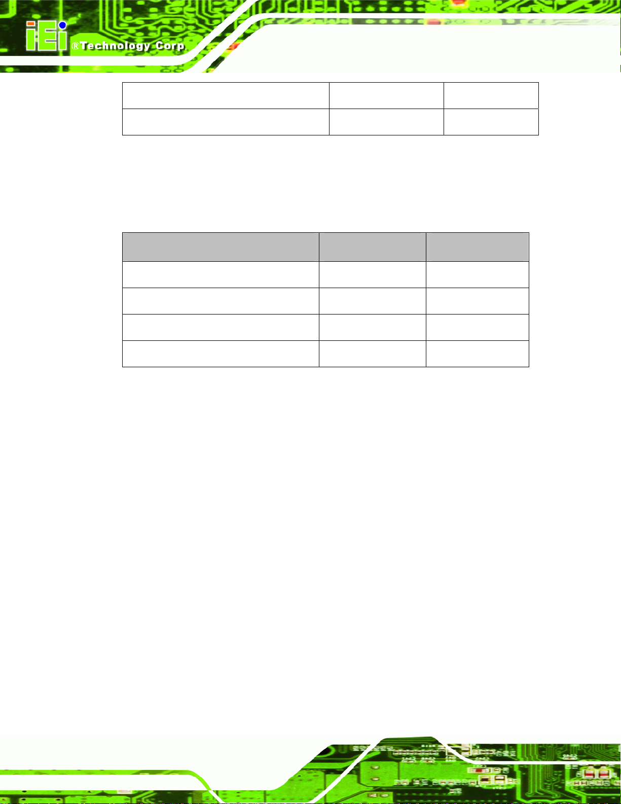
USB connector 8-pin header CN13
VCC ISA power connector 3-pin header CN1
Table 3-1: Peripheral Interface Connectors
3.1.3 External Interface Panel Connectors
The table below lists the connectors on the external I/O panel.
Connector Type Label
Ethernet connector RJ-45 CN22
Keyboard and mouse connector PS/2 CN24
Serial port DB-9 male CN21
IOWA-LX-600 Half-size CPU Card
VGA connector DB-15 female CN23
Table 3-2: Rear Panel Connectors
3.2 Internal Peripheral Connectors
The section describes all of the connectors on the IOWA-LX-600.
3.2.1 ATX Power Enable Connector
CN Label:
CN Type:
CN Location:
CN Pinouts:
The ATX power supply enable connector enables the IOWA-LX-600 to be connected to an
ATX power supply. In default mode, the IOWA-LX-600 can only use an AT power supply.
CN3
3-pin wafer (1x3)
5Figure 3-2
See
5Table 3-3
See
Page 16
To enable an ATX power supply the AT Power Select jumper must also be configured.
Page 31

IOWA-LX-600 Half-size CPU Card
Figure 3-2: ATX Power Supply Enable Connector Location
PIN DESCRIPTION
1 GND
2 PS-ON
3 +5V Standby
Table 3-3: ATX Power Supply Enable Connector Pinouts
3.2.2 Audio Connector (10-pin)
CN Label:
CN Type:
CN Location:
CN Pinouts:
The 10-pin audio connector is connected to external audio devices including spea kers and
microphones for the input and output of audio signals to and from the system.
CN19
10-pin box header (2x5)
5Figure 3-3
See
5Table 3-4
See
Page 17
Page 32

IOWA-LX-600 Half-size CPU Card
Figure 3-3: Audio Connector Pinouts (10-pin)
PIN DESCRIPTION PIN DESCRIPTION
1 Line out (Right) 2 Line in (Right)
3 GND 4 GND
5 Line out (Left) 6 Line in (Left)
7 GND 8 GND
9 MIC1 in 10 MIC2 in
Table 3-4: Audio Connector Pinouts (10-pin)
3.2.3 Backlight Inverter Connector
CN Label:
CN Type:
CN Location:
CN Pinouts:
The backlight inverter connector provides the backlight on the LCD display connected to
CN7
5-pin wafer (1x5)
5Figure 3-4
See
5Table 3-5
See
Page 18
the IOWA-LX-600 with +12V of power.
Page 33

IOWA-LX-600 Half-size CPU Card
Figure 3-4: Backlight Inverter Connector Pinout Locations
PIN DESCRIPTION
1 GND
2 GND
3 +12V
4 GND
5 LCD Enable
Table 3-5: Backlight Inverter Connector Pinouts
3.2.4 Battery Connector
CN Label:
CN Type:
CN Location:
CN Pinouts:
The battery connector is connected to a backup battery. The battery connector is also
used to reset the CMOS memory if the incorrect BIOS settings have been made and the
system cannot boot up.
CN14
2-pin wafer (1x2)
5Figure 3-5
See
5Table 3-6
See
Page 19
Page 34

IOWA-LX-600 Half-size CPU Card
Figure 3-5: Battery Connector Location
PIN NO. DESC RIPTION
1 Battery+
2 Ground
Table 3-6: Battery Connector Pinouts
3.2.5 CompactFlash® Socket
CN Label:
CN Type:
CN Location:
CN Pinouts:
A CF Type I or Type II memory card can be inserted to the CF socket on the solder side of
the IOWA-LX-600.
CN28 (solder side)
50-pin CF Type II slot
5Figure 3-6
See
5Table 3-7
See
Page 20
Page 35

IOWA-LX-600 Half-size CPU Card
Figure 3-6: CF Card Socket Location
PIN DESCRIPTION PIN DESCRIPTION
1 GROUND 26 CFD2
2 SDD3 27 SDD11
3 SDD4 28 SDD12
4 SDD5 29 SDD13
5 SDD6 30 SDD14
6 SDD7 31 SDD15
7 SDCS1# 32 SDCS3#
8 GROUND 33 N/C
9 GROUND 34 SDIOR#
10 GROUND 35 SDIOW#
11 GROUND 36 VCC
12 GROUND 37 IRQ15
13 VCC 38 VCC
14 GROUND 39 MASTER/SLAVE
15 GROUND 40 N/C
16 GROUND 41 RESET#
17 GROUND 42 SIORDY
18 SDA2 43 SDDREQ
19 SDA1 44 SDDACK#
20 SDA0 45 HD_LED2
21 SDD0 46 PDIAG#
22 SDD1 47 SDD8
Page 21
Page 36

PIN DESCRIPTION PIN DESCRIPTION
23 SDD2 48 SDD9
24 N/C 49 SDD10
25 CFD1 50 GROUND
Table 3-7: CF Card Socket Pinouts
3.2.6 Digital Input/Output (DIO) Connector
IOWA-LX-600 Half-size CPU Card
CN Label:
CN Type:
CN Location:
CN Pinouts:
CN16
10-pin header (2x5)
5Figure 3-7
See
5Table 3-8
See
The digital input/output connector is managed through a Super I/O chip. The DIO
connector pins are user programmable.
Page 22
Figure 3-7: DIO Connector Locations
PIN DESCRIPTION PIN DESCRIPTION
1 Ground 2 +5V
3 Output 0 4 Output 1
Page 37

IOWA-LX-600 Half-size CPU Card
5 Output 2 6 Output 3
7 Input 0 8 Input 1
9 Input 2 10 Input 3
Table 3-8: DIO Connector Pinouts
3.2.7 Fan Connector (+5V)
CN Label:
CN Type:
CN Location:
CN Pinouts:
CN8
3-pin wafer
5Figure 3-8
See
5Table 3-9
See
The cooling fan connector provides a 5V, 500mA current to a system cooling fan. The
connector has a "rotation" pin to get rotation signals from fans. Please note that only
specified fans can issue the rotation signals.
Figure 3-8: Fan Connector Location
PIN DESCRIPTION
1 GND
2 +5V
3 Rotation Signal
Table 3-9: Fan Connector Pinouts
Page 23
Page 38

3.2.8 Floppy Disk Connector
IOWA-LX-600 Half-size CPU Card
CN Label:
CN Type:
CN Location:
CN Pinouts:
CN9
34-pin header (2x17)
5Figure 3-9
See
5Table 3-10
See
The floppy disk connector is connected to a floppy disk drive.
Page 24
Figure 3-9: FDD Connector Location
PIN DESCRIPTION PIN DESCRIPTION
1 GROUND 2 DRVDEN0
3 GROUND 4 N/C
5 GROUND 6 N/C
7 GROUND 8 INDEX#
9 GROUND 10 MOT0#11 GROUND 12 N/C
13 GROUND 14 DSA#15 GROUND 16 N/C
17 GROUND 18 DIR#
Page 39

IOWA-LX-600 Half-size CPU Card
PIN DESCRIPTION PIN DESCRIPTION
19 GROUND 20 STEP#
21 GROUND 22 WDATA#
23 GROUND 24 WGATE#
25 GROUND 26 TRK0#
27 GROUND 28 WP#
29 N/C 30 RDATA#
31 GROUND 32 HDSEL#
33 N/C 34 DSKCHG#
Table 3-10: FDD Connector Pinouts
3.2.9 Front Panel Connector (8-pin)
CN Label:
CN Type:
CN Location:
CN Pinouts:
CN6
8-pin header (2x4)
5Figure 3-10
See
5Table 3-11
See
The front panel connector connects to the powe r b utton, reset b utton an d hard drive LE Ds
located on the front panel of the chassis.
Figure 3-10: Front Panel Connector Pinout Locations
Page 25
Page 40

PIN DESCRIPTION PIN DESCRIPTION
1 PWRBTN 2 +5V
3 GROUND 4 GROUND
5 +5V 6 RESET
7 HDDLED- 8 GROUND
Table 3-11: Front Panel Connector Pinouts
3.2.10 IDE Connector (40-pin)
IOWA-LX-600 Half-size CPU Card
CN Label:
CN Type:
CN Location:
CN Pinouts:
CN11
40-pin box header (2x20)
5Figure 3-11
See
5Table 3-12
See
One 40-pin IDE device connector on the IOWA-LX-600 supports connectivity to two hard
disk drives.
Page 26
Figure 3-11: IDE Device Connector Locations
Page 41

IOWA-LX-600 Half-size CPU Card
PIN DESCRIPTION PIN DESCRIPTION
1 RESET# 2 GROUND
3 DATA 7 4 DATA 8
5 DATA 6 6 DATA 9
7 DATA 5 8 DATA 10
9 DATA 4 10 DATA 11
11 DATA 3 12 DATA 12
13 DATA 2 14 DATA 13
15 DATA 1 16 DATA 14
17 DATA 0 18 DATA 15
19 GROUND 20 N/C
21 DRQ 22 GROUND
23 IOW# 24 GROUND
25 IOR# 26 GROUND
27 CHRDY 28 (PULL LOW TO GND)
29 DACK# 30 GROUND
31 INTERRUPT 32 N/C
33 SA1 34 N/C
35 SA0 36 SA2
37 HDC CS0# 38 HDC CS1#
39 HDD ACTIVE# 40 GROUND
Table 3-12: IDE Connector Pinouts
3.2.11 Infrared Interface Connector (5-pin)
CN Label:
CN Type:
CN Location:
CN Pinouts:
CN15
5-pin header (1x5)
5Figure 3-12
See
6Table 3-13
See
The infrared interface connector supports both Serial Infrared (SIR) and Amplitude Shift
Key Infrared (ASKIR) interfaces.
Page 27
Page 42

IOWA-LX-600 Half-size CPU Card
Figure 3-12: Infrared Connector Pinout Locations
PIN DESCRIPTION
1 VCC
2 NC
3 IR-RX
4 GND
5 IR-TX
Table 3-13: Infrared Connector Pinouts
3.2.12 Keyboard/Mouse Connector
CN Label:
CN Type:
CN Location:
CN Pinouts:
The keyboard and mouse connector can be connected to a standard PS/2 cable or PS/2
Y-cable to add keyboard and mouse functionality to the system.
CN25
6-pin wafer (1x6)
6Figure 3-13
See
6Table 3-14
See
Page 28
Page 43

IOWA-LX-600 Half-size CPU Card
Figure 3-13: Keyboard/Mouse Connector Location
PIN DESCRIPTION
1 +5V
2 Mouse Data
3 Mouse Clock
4 Keyboard Data
5 Keyboard Clock
6 Ground
Table 3-14: Keyboard/Mouse Connector Pinouts
3.2.13 Parallel Port Connector
CN Label:
CN Type:
CN Location:
CN Pinouts:
The 26-pin parallel port connector connects to a parallel port connector interface or some
other parallel port device such as a printer.
CN17
26-pin box header
6Figure 3-14
See
6Table 3-15
See
Page 29
Page 44

IOWA-LX-600 Half-size CPU Card
Figure 3-14: Parallel Port Connector Location
PIN DESCRIPTION PIN DESCRIPTION
1 STROBE# 2 AUTO FORM FEED #
3 DATA 0 4 ERROR#
5 DATA 1 6 INITIALIZE
7 DATA 2 8 PRINTER SELECT LN#
9 DATA 3 10 GROUND
11 DATA 4 12 GROUND
13 DATA 5 14 GROUND
15 DATA 6 16 GROUND
17 DATA 7 18 GROUND
19 ACKNOWLEDGE 20 GROUND
21 BUSY 22 GROUND
23 PAPER EMPTY 24 GROUND
25 PRINTER SELECT 26 N/C
Table 3-15: Parallel Port Connector Pinouts
3.2.14 Power Connector
Page 30
CN Label:
CN Type:
CN2
4-pin power connector (1x4)
Page 45

IOWA-LX-600 Half-size CPU Card
CN Location:
CN Pinouts:
6Figure 3-15
See
6Table 3-16
See
The 4-pin power connector is connected to a power supply.
Figure 3-15: Power Connector Location
PIN DESCRIPTION
1 +5V
2 GND
3 GND
4 +12V
Table 3-16: Power Connector Pinouts
3.2.15 SATA Drive Connectors (Optional)
CN Label:
CN Type:
CN Location:
CN Pinouts:
The SATA connectors connect to SATA 1.5Gb/s hard drives or optical drives. The SATA
connectors are option and only for IOWA-LX-600S model.
CN26 and CN27
7-pin SATA drive connectors
6Figure 3-16
See
6Table 3-17
See
Page 31
Page 46

IOWA-LX-600 Half-size CPU Card
Figure 3-16: SATA Drive Connector Locations
PIN DESCRIPTION
1 GND
2 TX+
3 TX4 GND
5 RX6 RX+
7 GND
Table 3-17: SATA Drive Connector Pinouts
3.2.16 Serial Port Connector (RS-232/422/485)
CN Label:
CN Type:
CN Location:
CN Pinouts:
This connector provides RS-232 communications via pin 1 ~ pin 10 as COM2.
CN18
14-pin box header (2x7)
6Figure 3-17
See
6Table 3-18
See
Page 32
Pin 11 ~ pin 14 of this connector provides RS-422 or RS-485 communications as COM3.
Page 47

IOWA-LX-600 Half-size CPU Card
Figure 3-17: Internal Serial Port Connector Pinout Locations
PIN DESCRIPTION PIN DESCRIPTION
1 Data Carrier Direct (DCD) 2 Data Set Ready (DSR)
3 Receive Data (RXD) 4 Request To Send (RTS)
5 Transmit Data (TXD) 6 Clear To Send (CTS)
7 Data Terminal Ready (DTR) 8 Ring Indicator (RI)
9 Ground (GND) 10 Ground (GND)
11 TxD485+ 12 TxD485#
13 RxD485+ 14 RxD485#
Table 3-18: Internal Serial Port Connector Pinouts
3.2.17 TTL Connector
CN Label:
CN Type:
CN Location:
CN Pinouts:
CN10
40-pin crimp (2x20)
6Figure 3-18
See
6Table 3-19
See
The 40-pin TTL connector can be connected to a TFT LCD panel .
Page 33
Page 48

IOWA-LX-600 Half-size CPU Card
Figure 3-18: TFT LCD Connector Pinout Locations
PIN DESCRIPTION PIN DESCRIPTION
1 VCD_VCC 2 VCD_VCC
3 GROUND 4 GROUND
5 VCD_VCC 6 VCD_VCC
7 I_SDATA 8 GROUND
9 TFT_B0 10 TFT_B1
11 TFT_B2 12 TFT_B3
13 TFT_B4 14 TFT_B5
15 TFT_B6 16 TFT_B7
17 TFT_G0 18 TFT_G1
19 TFT_G2 20 TFT_G3
21 TFT_G4 22 TFT_G5
23 TFT_G6 24 TFT_G7
25 TFT_R0 26 TFT_R1
27 TFT_R2 28 TFT_R3
29 TFT_R4 30 TFT_R5
31 TFT_R6 32 TFT_R7
33 GROUND 34 GROUND
Page 34
35 FPCLK 36 VSYNC
37 LCD_EN 38 HSYNC
39 I_SCLK 40 DISPEN
Table 3-19: TFT LCD Port Connector Pinouts
Page 49

IOWA-LX-600 Half-size CPU Card
3.2.18 Internal USB Connectors
CN Label:
CN Type:
CN Location:
CN Pinouts:
CN12 and CN13
8-pin header (2x4)
6Figure 3-19
See
6Table 3-20
See
The 2x4 USB pin connectors each provide connectivity to two USB 2.0 ports. Each USB
connector can support two USB devices. The USB ports are used for I/O bus expansion.
Figure 3-19: USB Connector Pinout Locations
PIN DESCRIPTION PIN DESCRIPTION
1 VCC 2 GROUND
3 DATA- 4 DATA+
5 DATA+ 6 DATA7 GROUND 8 VCC
Table 3-20: USB Port Connector Pinouts
Page 35
Page 50

3.2.19 -VCC Power Connector
IOWA-LX-600 Half-size CPU Card
CN Label:
CN Type:
CN Location:
CN Pinouts:
CN1
3-pin header (1x3)
6Figure 3-19
See
6Table 3-20
See
The –VCC power connector provides –5V and –12V power to legacy expansion ISA
devices installed on the backplane. The power supply is connected to the –VCC power
connecter and transmitted to the ISA devices through the backplane.
Page 36
Figure 3-20: -VCC Power Connector Pinout Locations
PIN DESCRIPTION
1 -5V
2 GROUND
3 -12V
Table 3-21: -VCC Power Connector Pinouts
Page 51

IOWA-LX-600 Half-size CPU Card
3.3 External Peripheral Interface Connectors
The IOWA-LX-600 external peripheral interface connectors are listed below and shown in
6Figure 3-21:
1 x PS/2 Keyboard/Mouse connector
1 x RJ-45 Ethernet connector
1 x Serial communications port
1 x VGA port
Figure 3-21: IOWA-LX-600 On-board External Interface Connectors
3.3.1 PS/2 Keyboard/Mouse Connector
CN Label:
CN T ype:
CN Location:
CN Pinouts:
The PS/2 connector can be connected to a keyboard or mouse.
CN24
PS/2
6Figure 3-21
See
See
6Figure 3-22 and 6Table 3-22
Figure 3-22: PS/2 Pinouts
Page 37
Page 52

PIN DESCRIPTION PIN DESCRIPTION
1 KEYBBOARD DATA 2 MOUSE DATA
3 GND 4 GND
5 KEYBOARD CLOCK 6 MOUSE CLOCK
Table 3-22: PS/2 Connector Pinouts
3.3.2 RJ-45 Ethernet Connector
IOWA-LX-600 Half-size CPU Card
CN Label:
CN Type:
CN Location:
CN Pinouts:
CN22
RJ-45
6Figure 3-21
See
6Table 3-23
See
The RJ-45 Ethernet connector on the IOWA-LX-600 provides connectivity to a 10/100
megabit Ethernet connection between the IOWA-LX-600 and a Local Area Network (LAN)
through a network hub.
PIN DESCRIPTION PIN DESCRIPTION
1 TX+ 8 N/C
2 GROUND 9 ACT_LED3 TX- 10 ACT_LED+
4 RX+ 11 LINK_LED 5 GROUNG 12 LINK_LED+
Page 38
6 RX- 13 GROUND
7 N/C 14 GROUND
Table 3-23: RJ-45 Ethernet Connector Pinouts
Page 53

IOWA-LX-600 Half-size CPU Card
Figure 3-23: RJ-45 Connector
The RJ-45 Ethernet connector has two status LEDs, one green and one yello w. The green
LED indicates activity on the port and the yellow LED indicates the port is linked.
SPEED LED LINK LED
Status Description Status Description
GREEN
ON: 100MB
OFF: 10MB
YELLOW
ON: Linked
Flashing: Activity
Table 3-24: J7 Connector LEDs
3.3.3 Serial Port Connector (COM 1)
CN Label:
CN Type:
CN Location:
CN Pinouts:
The 9-pin DB-9 COM 1 serial port connector is connected to RS-232 serial
communications devices.
PIN DESCRIPTION PIN DESCRIPTION
1 DCD1 2 RXD1
CN21
DB-9 connector
6Figure 3-21
See
6Table 3-25 and 6Figure 3-24
See
3 TXD1 4 DTR1
5 GND 6 DSR1
7 RTS1 8 CTS1
9 COM_RI1
Table 3-25: RS-232 Serial Port (COM 1) Pinouts
Page 39
Page 54

Figure 3-24: COM1 Pinout Locations
3.3.4 VGA Connector
IOWA-LX-600 Half-size CPU Card
CN Label:
CN Type:
CN Location:
CN Pinouts:
CN23
DB-15
6Figure 3-21
See
6Table 3-26
See
The standard 15-pin female DB-15 VGA connector connects to a CRT or LCD monitor
directly.
PIN DESCRIPTION PIN DESCRIPTION PIN DESCRIPTION
1 RED 6 GROUND 11 NC
2 GREEN 7 GROUND 12 DDCDAT
3 BLUE 8 GROUND 13 HSYNC
4 NC 9 NC 14 VSYNC
5 GROUND 10 GROUND 15 DDCCLK
Table 3-26: VGA Connector Pinouts
Page 40
Page 55

IOWA-LX-600 Half-size CPU Card
Chapter
4
4 Installation
Page 41
Page 56

4.1 Anti-static Precautions
WARNING:
Failure to take ESD precautions during the installation of the
IOWA-LX-600 may result in permanent damage to the IOWA-LX-600
and severe injury to the user.
Electrostatic discharge (ESD) can cause serious damage to electronic components,
including the IOWA-LX-600. Dry climates are especially susceptible to ESD. It is therefore
critical that whenever the IOWA-LX-600 or any other electrical component is handled, the
following anti-static precautions are strictly adhered to.
Wear an anti-static wristband: Wearing a simple an ti-static wristband can
IOWA-LX-600 Half-size CPU Card
help to prevent ESD from damaging the board.
Self-grounding: Before handling the board, touch any grounded conducting
material. During the time the board is handled, frequently touch any
conducting materials that are connected to the ground.
Use an anti-static pad: When configuring the IOWA-LX-600, place it on an
antic-static pad. This reduces the possibility of ESD damaging the
IOWA-LX-600.
Only handle the edges of the PCB: When handling the PCB, hold the PCB
by the edges.
Page 42
Page 57

IOWA-LX-600 Half-size CPU Card
4.2 Installation Considerations
NOTE:
The following installation notices and installation considerations should
be read and understood before the IOWA-LX-600 is installed. All
installation notices pertaining to the installation of the IOWA-LX-600
should be strictly adhered to. Failing to adhere to these precautions
may lead to severe damage of the IOWA-LX-600 and injury to the
person installing the motherboard.
4.2.1 Installation Notices
WARNING:
The installation instructions described in this manual should be carefully
followed in order to prevent damage to the IOWA-LX-600, IOWA-LX-600
components and injury to the user.
Before and during the installation please DO the following:
Read the user manual:
o The user manual provides a complete description of the IOWA-LX-600
installation instructions and configuration options.
Wear an electrostatic discharge cuff (ESD):
o Electronic components are easily damaged by ESD. Wearing an ESD cuff
removes ESD from the body and helps prevent ESD damage.
Place the IOWA-LX-600 on an antistatic pad:
o When installing or configuring the motherboard, place it on an antistatic
pad. This helps to prevent potential ESD damage.
Turn all power to the IOWA-LX-600 off:
Page 43
Page 58

o When working with the IOWA-LX-600, make sure that it is disconnected
Before and during the installation of the IOWA-LX-600 DO NOT:
Remove any of the stickers on the PCB board. These stickers are required for
warranty validation.
Use the product before verifying all the cables and power connectors are
properly connected.
Allow screws to come in contact with the PCB circuit, connector pins, or its
components.
4.3 Unpacking
When the IOWA-LX-600 is unpacked, please check all the unpacking list items listed in
Chapter 3 are indeed present. If any of the unpacking list items are not available please
IOWA-LX-600 Half-size CPU Card
from all power supplies and that no electricity is being fed into the system.
contact the IOWA-LX-600 vendor reseller/vendor where the IOWA-LX-600 was purchased
or contact an IEI sales representative.
4.4 SO-DIMM Installation
NOTE:
Using incorrectly specified SO-DIMM may cause permanently damage
the IOWA-LX-600. Please make sure the purchased SO-DIMM
complies with the memory specifications of the IOWA-LX-600.
SO-DIMM specifications compliant with the IOWA-LX-600 are listed in
Chapter 2.
To install a SO-DIMM into a SO-DIMM socket, please follow the steps below and refer to
6Figure 4-1.
Page 44
Page 59

IOWA-LX-600 Half-size CPU Card
Figure 4-1: SO-DIMM Installation
Step 1: Locate the SO-DIMM socket. Place the IOWA-LX-600 on an anti-static pad
with the solder side facing up.
Step 2: Align the SO-DIMM with the socket. The SO-DIMM must be oriented in such a
way that the notch in the middle of the SO-DIMM must be aligned with the
plastic bridge in the socket.
Step 3: Insert the SO-DIMM. Push the SO-DIMM chip into the socket at an angle. (See
6Figure 4-1)
Step 4: Open the SO-DIMM socket arms. Gently pull the arms of the SO-DIMM socket
out and push the rear of the SO-DIMM down. (See
Step 5: Secure the SO-DIMM. Release the arms on the SO-DIMM socket. They clip into
place and secure the SO-DIMM in the socket.Step 0:
4.5 CF Card Installation
NOTE:
The IOWA-LX-600 can support both CF Type I cards and CF Type II
cards. For the complete specifications of the supported CF cards
please refer to Chapter 2.
6Figure 4-1)
Page 45
Page 60

To install the a CF card (Type I or Type II) onto the IOWA-LX-600, please follow the steps
below:
Step 1: Locate the CF card socket. Place the IOWA-LX-600 on an anti-static pad with
the solder side facing up. Locate the CF card on the solder side.
Step 2: Align the CF card. Make sure the CF card is properly aligned with the CF
socket.
Step 3: Insert the CF card. Gently insert the CF card into the socket making sure the
IOWA-LX-600 Half-size CPU Card
socket pins are properly inserted into the socket. See
6Figure 4-2.
Page 46
Figure 4-2: CF Card Installation
Page 61

IOWA-LX-600 Half-size CPU Card
4.6 Jumper Settings
NOTE:
A jumper is a metal bridge used to close an
electrical circuit. It consists of two or three metal
pins and a small metal clip (often protected by a
plastic cover) that slides over the pins to connect
them. To CLOSE/SHORT a jumper means
connecting the pins of the jumper with the plastic
clip and to OPEN a jumper means removing the
plastic clip from a jumper.
Before the IOWA-LX-600 is installed in the system, the jumpers must be set in accordanc e
Figure 4-3: Jumper Locations
with the desired configuration. The jumpers on the IOWA-LX-600 are listed in
Description Type Label
AT/ATX power mode setting 2-pin header JP2
CompactFlash® card setup 3-pin header JP7
COM3 RS-422/485 select 3-pin header JP3
LCD voltage select 3-pin header JP5
LCD TTL clock select 3-pin header JP6
Table 4-1: Jumpers
4.6.1 AT/ATX Power Select
Jumper Label:
Jumper Type:
66Table 4-1.
JP2
2-pin header
Jumper Settings:
Jumper Location:
6Table 4-2
See
6Figure 4-4
See
Page 47
Page 62

IOWA-LX-600 Half-size CPU Card
The AT/ATX Power Select jumper specifies the systems power mode as AT or ATX.
AT/ATX Power Select jumper settings are shown in
Setting Description
Short Use AT power (Default)
Open Use ATX power
6Table 4-2.
Table 4-2: AT/ATX Power Select Jumper Settings
The location of the AT/ATX Power Select jumper is shown in 6Figure 4-4 below.
Figure 4-4: AT/ATX Power Select Jumper Location
4.6.2 CF Card Setup
Jumper Label: JP7
Jumper Type:
Jumper Settings:
Jumper Location:
The CompactFlash® slot is connected through an IDE connection. This jumper sets the
CompactFlash® card as the master or slave IDE device.
Page 48
3-pin header
6Table 4-3
See
6Figure 4-5
See
Page 63

IOWA-LX-600 Half-size CPU Card
Setting Description
Short 1-2 Slave
Short 2-3 Master
Table 4-3: CompactFlash® Setup Jumper Settings
Figure 4-5: CompactFlash® Setup Jumper Location
4.6.3 COM 3 Function Select
Jumper Label: JP3
Jumper Type:
Jumper Settings:
Jumper Location:
3-pin header
6Table 4-4
See
6Figure 4-6
See
The COM 3 Function Select jumper sets the communication protocol used by the third
serial communications port (COM 3) as RS-422 or RS-485. The COM 3 Function Select
settings are shown in the table below.
Setting Description
Short 1-2 RS-422 (Default)
Short 2-3 RS-485
Table 4-4: COM 3 Function Select Jumper Settings
Page 49
Page 64

Figure 4-6: COM 3 Function Select Jumper Location
4.6.4 LCD Voltage Select
IOWA-LX-600 Half-size CPU Card
WARNING:
Incorrect voltages can destroy the LCD panel. Make sure to select a
voltage that matches the voltage required by the LCD panel.
Jumper Label: JP5
Jumper Type:
Jumper Settings:
Jumper Location:
The LCD voltage selection jumper sets the voltage of the power supplied to the LCD
panel.
Setting Description
Short 1-2 +3.3 V (Default)
Short 2-3 +5.0 V
3-pin header
6Table 4-5
See
6Figure 4-7
See
Page 50
Table 4-5: LVDS Voltage Selection Jumper Settings
Page 65

IOWA-LX-600 Half-size CPU Card
Figure 4-7: LVDS Voltage Selection Jumper Locations
4.6.5 LCD Clock Select Jumper
Jumper Label: JP6
Jumper Type:
Jumper Settings:
Jumper Location:
3-pin header
6Table 4-1
See
6Figure 4-8
See
This jumper inverts the LCD clock of the LCD connector (CN10).
Setting Description
Short 1-2 FPCLK
Short 2-3 FPCLK#
Table 4-6: LCD Clock Select Jumper Settings
Figure 4-8: LCD Clock Select Jumper Location
Page 51
Page 66

4.7 Chassis Installation
4.7.1 Airflow
WARNING:
Airflow is critical to the cooling of the CPU and other onboard
components. The chassis in which the IOWA-LX-600 must have air
vents to allow cool air to move into the system and hot air to move out.
The IOWA-LX-600 must be installed in a chassis with ventilation holes on the sides
allowing airflow to travel through the heat sink surface. In a system with an individual
power supply unit, the cooling fan of a power supply can also help generate airflow
through the board surface.
IOWA-LX-600 Half-size CPU Card
4.7.2 Backplane Installation
Before the IOWA-LX-600 can be installed into the chassis, a backplane must first be
installed. Please refer to the installation instructions that came with the backplane and the
chassis to see how to install the backplane into the chassis.
NOTE:
IEI has a wide range of backplanes available. Please contact a vendor,
reseller or an IEI sales representative at
IEI website (
available chassis.
2http://www.ieiworld.com.tw) to find out more about the
2sales@iei.com.tw or visit the
4.7.3 CPU Card Installation
To install the CPU card onto the backplane, carefully align the CPU card edge connector
Page 52
with the CPU card socket on the backplane. To do this, please refer to the reference
material that came with the backplane. Next, secure the CPU card to the chassis. To do
this, please refer to the reference material that came with the chassis.
Page 67

IOWA-LX-600 Half-size CPU Card
4.8 Internal Peripheral Device Connections
This section outlines the installation of peripheral devices to the onboard connectors
4.8.1 5.1 Channel Audio Kit Installation
The audio kit attaches to the audio connector. The audio kit provides 5.1 channel audio.
To install the audio kit, please refer to the steps below:
Step 1: Connect the cable to the audio kit. Connect the included cable to the audio kit.
Make sure pin 1 aligns with the marked pin.
Step 2: Conect the cable to the board. Connect the other end of the cable to the board.
Make sure to line up the marked pin 1.
Figure 4-9: 5.1 Channel Audio Kit
Step 3: Mount the audio kit onto the chassis. Once the audio kit is connected to the
board, secure the audio kit bracket to the system chassis.
Step 4: Connect the audio devices. Connect speakers and external audio sources to
the audio jacks on the audio kit.
Step 5: Install the driver. Install the 5.1 channel audio driver included with the board.
Step 0:
Page 53
Page 68

4.8.2 ATA Flat Cable Connection
The IDE cable can connect to one or two IDE devices. To connect the IDE devices, follow
the steps below.
Step 1: Locate the IDE connector. Locate the IDE connector on the board.
Step 2: Insert the connector. Connect the IDE cable connector to the on-board
IOWA-LX-600 Half-size CPU Card
connector. See
can only be inserted in one direction.
6Figure 4-10. A key on the front of the cable connector ensures it
Page 54
Figure 4-10: IDE Cable Connection
Step 3: Connect the cable to an IDE device. Connect the two connectors on the other
side of the cable to one or two IDE devices. Make sure that pin 1 on the cable
corresponds to pin 1 on the connector. Step 0:
Page 69

IOWA-LX-600 Half-size CPU Card
4.8.3 USB Cable
The IOWA-LX-600 is shipped with a dual port USB 2.0 cable. To connect the USB cable
connector, please follow the steps below.
Step 1: Locate the connectors. The locations of the USB connectors are shown in
Chapter 3.
WARNING:
If the USB pins are not properly aligned, the USB device can burn out.
Step 2: Align the connectors. The cable has two connectors. Correctly align pin 1on
each cable connector with pin 1 on the IOWA -LX-600 USB connector.
Step 3: Insert the cable connectors. Once the cable connectors are properly aligned
with the USB connectors on the IOWA-LX-600, connect the cable conne ctors to
the on-board connectors. See
6Figure 4-11.
Figure 4-11: Dual USB Cable Connection
Page 55
Page 70

Step 4: Attach the bracket to the chassis. The USB 2.0 connectors a re attached to a
bracket. To secure the bracket to the chassis please refer to the installation
instructions that came with the chassis.Step 0:
IOWA-LX-600 Half-size CPU Card
4.9 External Peripheral Interface Connection
Devices can be connected to the external connectors. To install external devices, follow
the directions in the subsections below.
4.9.1 LAN Connection (Single Connector)
There is one external RJ-45 LAN connector. The RJ-45 connector enables connection to
an external network. To connect a LAN cable with an RJ-45 connector, please follow the
instructions below.
Step 1: Locate the RJ-45 connectors. The location of the LAN connector is shown in
Chapter 4.
Step 2: Align the connectors. Align the RJ-45 connector on the LAN cable with one of
the RJ-45 connectors on the IOWA-LX-600. See
6Figure 4-12.
Page 56
Figure 4-12: LAN Connection
Page 71

IOWA-LX-600 Half-size CPU Card
Step 3: Insert the LAN cable RJ-45 connector. Once aligned, gently inse rt the LAN
cable RJ-45 connector into the on-board RJ-45 connector. Step 0:
4.9.2 PS/2 Y-Cable Connection
The IOWA-LX-600 has a PS/2 connector on the external peripheral interface panel. The
dual PS/2 connector is connected to the PS/2 Y-cable that came with the IOWA-LX-600.
One of the PS/2 cables is connected to a keyboard and the other to a mouse to the
system. Follow the steps below to connect a keyboard and mouse to the IOWA-LX-600.
Step 1: Locate the dual PS/2 connector. The location of the PS/2 connector is shown
in Chapter 3.
Step 2: Insert the keyboard/mouse connector. Insert the PS/2 connector on the end
of the PS/2 y-cable into the external PS/2 connector. See
6Figure 4-13.
Figure 4-13: PS/2 Keyboard/Mouse Connector
Step 3: Connect the keyboard and mouse. Connect the keyboard and mouse to the
appropriate connector. The keyboard and mouse connectors can be
Page 57
Page 72

distinguished from each other by looking at the small graphic at the top of the
connector. Step 0:
4.9.3 Serial Device Connection
The IOWA-LX-600 has a single female DB-9 connector on the external peripheral
interface panel for a serial device. Follow the steps below to connect a serial device to the
IOWA-LX-600.
Step 1: Locate the DB-9 connector. The location of the DB-9 connector is shown in
Chapter 3.
Step 2: Insert the serial connector. Insert the DB-9 connector of a serial device into
IOWA-LX-600 Half-size CPU Card
the DB-9 connector on the external peripheral interface. See
6Figure 4-14.
Page 58
Figure 4-14: Serial Device Connector
Page 73

IOWA-LX-600 Half-size CPU Card
Step 3: Secure the connector. Secure the serial device connector to the external
interface by tightening the two retention screws on either side of the connector.
Step 0:
4.9.4 VGA Monitor Connection
The IOWA-LX-600 has a single female DB-15 connector on the external peripheral
interface panel. The DB-15 connector is connected to a CRT or VGA monitor. To connect
a monitor to the IOWA-LX-600, please follow the instructions below.
Step 1: Locate the female DB-15 connector. The location of the female DB-15
connector is shown in Chapter 3.
Step 2: Align the VGA connector. Align the male DB-15 connector on the VGA scree n
cable with the female DB-15 connector on the external peripheral interface.
Step 3: Insert the VGA connector. Once the connectors are properly aligned with the
insert the male connector from the VGA screen into the female connector on the
IOWA-LX-600. See
6Figure 4-15.
Figure 4-15: VGA Connector
Page 59
Page 74

Step 4: Secure the connector. Secure the DB-15 VGA connector from the VGA
monitor to the external interface by tightening the two retention screws on either
side of the connector. Step 0:
4.10 Software Installation
All the drivers for the IOWA-LX-600 are on the CD that came with the system. To install
the drivers, please follow the steps below.
Step 1: Insert the CD into a CD drive connected to the system.
NOTE:
If the installation program doesn't start automatically:
IOWA-LX-600 Half-size CPU Card
Click "Start->My Computer->CD Drive->autorun.exe"
Step 2: The driver main menu appears (6Figure 4-16).
Page 60
Figure 4-16: Introduction Screen
Page 75

IOWA-LX-600 Half-size CPU Card
Step 3: Click IOWA-LX.
Step 4: A new screen with a list of available drivers appears (
6Figure 4-17).
Figure 4-17: Available Drivers
Step 5: Install all of the necessary drivers in this menu. Step 0:
Page 61
Page 76

IOWA-LX-600 Half-size CPU Card
Chapter
5
5 BIOS Screens
Page 62
Page 77

IOWA-LX-600 Half-size CPU Card
5.1 Introduction
The BIOS is programmed onto the BIOS chip. The BIOS setup program allows changes to
certain system settings. This chapter outlines the options that can be changed.
5.1.1 Starting Setup
The UEFI BIOS is activated when the computer is turned on. The setup program can be
activated in one of two ways.
1. Press the D
2. Press the D
appears on the screen.
If the message disappears, restart the computer and try again.
ELETE key as soon as the system is turned on or
ELETE key when the “Press Del to enter SETUP” message
5.1.2 Using Setup
Use the arrow keys to highlight items, press ENTER to select, press F1 for help and press
E
SC to quit. Navigation keys are shown below.
Key Function
Up arrow Move to the item above
Down arrow Move to the item below
Left arrow Move to the item on the left hand side
Right arrow Move to the item on the right hand side
Page up / + Increase the numeric value or make changes
Page down / - Decrease the numeric value or make changes
Esc Main Menu – Quit and do not save changes into CMOS
Status Page Setup Menu and Option Page Setup Menu -Exit current page and return to Main Menu
F1 General help, only for Status Page Setup Menu and Option
Page Setup Menu
F7 Load optimized defaults
Page 63
Page 78

F10 Save changes and Exit BIOS
Table 5-1: BIOS Navigation Keys
5.1.3 Getting Help
When F1 is pressed a small help window describing the appropriate keys to use and the
IOWA-LX-600 Half-size CPU Card
possible selections for the highlighted item appears. To exit the Help Window press E
or the F1 key again.
5.1.4 Unable to Reboot After Configuration Changes
If the system cannot be booted after changes are made, restore th e CMOS defaul ts. Refer
to Section
63.2.4 for more information.
5.1.5 Main BIOS Menu
Once the BIOS opens, the main menu (6BIOS Menu 1) appears.
Phoenix - AwardBIOS CMOS Setup Utility
> Standard CMOS Features
> Advanced BIOS Features
> Advanced Chipset Features
> Integrated Peripherals
> Power Management Setup
> PnP/PCI Configurations
> PC Health Status
Load Fail-Safe Defaults
Load Optimized Defaults
Set Supervisor Password
Set User Password
Save & Exit Setup
Exit Without Saving
SC
Esc=Quit
F10=Save & Exit Setup
Time, Date, Hard Disk Type...
BIOS Menu 1: Award BIOS Setup Utility
Page 64
↑ ↓=Select Item
Page 79

IOWA-LX-600 Half-size CPU Card
NOTE:
The following sections will completely describe the menus listed below
and the configuration options available to users.
The following menu options are seen in 6BIOS Menu 1.
Standard CMOS Features: Changes the basic system configuration.
Advanced BIOS Features: Changes the advanced system settings.
Advanced Chipset Features: Changes the chipset configuration feature s.
Integrated Peripherals: Changes the settings for integrated peripherals.
Power Management Setup: Configures power saving options.
PnP/PCI Configurations: Changes the advanced PCI/PnP settings.
PC Health Status: Monitors essential system parameters.
The following user configurable options are also available in
6BIOS Menu 1:
Load Fail-Safe Defaults
Use the Load Fail-Safe Defaults option to load failsafe default values for each BIOS
parameter in the setup menus. Press F6 for this operation on any page.
Load Optimized Defaults
Use the Load Optimized Defaults option to load optimal default values for each BIOS
parameter in the setup menus. Press F7 for this operation on any page.
Set Supervisor Password
Use the Set Supervisor Password option to set the supervisor password. By default, no
supervisor password is set. To install a supervisor password, sele ct this field and enter th e
password. After this option is selected, a red dialogue box appears with “Enter
Password: ”. Type the password and press E
“Confirm Password: ” dialogue box and press E
press E
NTER in the “Enter Password: ” dialogue box, then press any key in the
NTER. Retype the original password into the
NTER. To disable the password, simply
“Password Disabled !!!” dialogue box.
Page 65
Page 80

Set User Password
Use the Set User Password option to set the supervisor password. By default no user
password is set. To install a user password, select this field and enter the password. After
this option is selected, a red dialogue box appears with “Enter Password: ”. Type the
IOWA-LX-600 Half-size CPU Card
password and press E
dialogue box and press E
Password: ” dialogue box, then press any key in the “Password Disabled !!!” dialogue
box.
Save & Exit Setup
Use the Save & Exit Setup option to save any configuration changes made and exit the
BIOS menus.
Exit Without Saving
Use the Exit Without Saving option to exit the BIOS menus without saving any
configuration changes.
NTER. Retype the original password into the “Confirm Password: ”
NTER. To disable the password, simply press ENTER in the “Enter
5.2 Standard BIOS Features
Use the Standard BIOS Features BIOS menu (6BIOS Menu 2) to set basic BIOS
configuration options.
Page 66
Page 81

C
IOWA-LX-600 Half-size CPU Card
Phoenix - AwardBIOS CMOS Setup Utility
Standard CMOS Features
Date (mm:dd:yy) Mon, Jan 1 2007
Time (hh:mm:ss) 0:29:49
> IDE Primary Master [ None]
> IDE Primary Slave [ None]
Drive A [1.44M, 3.5 in.]
Item Help
Menu Level >
hange the day,
month, year and
century
Base Memory 640K
Extended Memory 97024K
Total Memory 97792K
↑ ↓:Move Enter:Select +/-/PU/PD:Value F10:Save Esc:Exit F1:General Help
F5=Previous Values F6:Fail-Safe Defaults F7 Optimized Defaults
BIOS Menu 2: Standard CMOS Features
Date [Day mm:dd:yyyy]
Use the Date option to set the system date
Time [hh/mm/ss]
Use the Time option to set the system time.
IDE Master and IDE Slave
When entering setup, BIOS auto detects the presence of IDE devices. The Standard
CMOS Features menu shows the status of the auto detected IDE devices. The following
IDE devices are detected and shown in the Standard CMOS Features menu:
IDE Primary Master
IDE Primary Slave
IDE device configurations are changed or set in the IDE Configuration menu (
6BIOS Menu
3). If an IDE device is detected, and one of the above listed two BIOS configuration
options is selected, the IDE configuration options shown in Section
65.2.1 appear.
Page 67
Page 82

Drive A [None]
Use the Drive A/B configuration to specify the floppy drive type installed in the system.
The floppy drive configuration options are:
Base Memory:
The Base Memory is NOT user configurable. The POST determines the amount of base
(or conventional) memory installed in the system. The value of the base memory is
IOWA-LX-600 Half-size CPU Card
None
360K, 5.25 in.
1.2M, 5.25 in.
720K, 3.5 in.
1.44M, 3.5in (Default)
2.88M, 3.5 in.
typically 512K for systems with 512K memory installed, or 640K for systems with 640K or
more memory installed.
Extended Memory
The Extended Memory is NOT user configurable. The BIOS determines how much
extended memory is present during the POST. This is the amount of memory above 1MB
located in the memory address map of the CPU.
Total Memory
The Total Memory is NOT user configurable.
5.2.1 IDE Primary Master/Slave
Use the IDE Primary Master/Slave menu (6BIOS Menu 3) to set or change the
master/slave IDE configurations.
Page 68
Page 83

IOWA-LX-600 Half-size CPU Card
Phoenix - AwardBIOS CMOS Setup Utility
IDE Primary Master
IDE HDD Auto-Detection [Press Enter]
IDE Primary Master [Auto]
Access Mode [Auto]
Capacity 0 MB
Cylinder 0
Header 0
Precomp 0
Landing Zone 0
Sector 0
↑ ↓:Move Enter:Select +/-/PU/PD:Value F10:Save Esc:Exit F1:General Help
F5=Previous Values F6:Fail-Safe Defaults F7 Optimized Defaults
BIOS Menu 3: IDE Channel Master
IDE HDD Auto-Detection [Press Enter]
Use the IDE HDD Auto-Detection option to enable BIOS to automatically detect the IDE
Item Help
Menu Level >
To auto-detect the
HDD’s size, head...
on this channel
settings. Select IDE HDD Auto-Detection and press E
the HDD type. Do not set this option manually.
IDE Primary Master [Auto]
Use the IDE Primary Master option to activate or deactivate the following drive channels:
Channel 0 Master
Channel 0 Slave
None
Auto
Manual
NTER. BIOS automatically detects
If no drives are connected to the IDE channel select this
option. Once set, this IDE channel becomes
inaccessible and any drives attached to it are
undetected.
(Default) Setting this option allows the device to be automatically
detected by the BIOS.
Selecting this option allows manual configuration of the
Page 69
Page 84

Access Mode [Auto]
The Access Mode option can only be configured if the BIOS configuration option is set to
either Manual or Auto. Use the Access Mode option to determine the hard disk BIOS
translation modes. Most systems now use hard drives with large capacities and therefore
either the LBA translation mode or auto mode should be selected.
IOWA-LX-600 Half-size CPU Card
device on the IDE channel in BIOS.
CHS
LBA
Large
Auto
Capacity
The Capacity specification indicates the storage capacity of the HDD installed in the
system.
Cylinder
Select this mode if the HDD capacity is less than
504MB.
Select this mode if the HDD capacity is more than
8.4GB.
This mode is an extended ECHS mode and while it
supports HDDs larger than 504MB, it is not
recommended.
(Default) If you are unsure of what access mode to set, select this
option.
Head
Precomp
Page 70
The Cylinder specification indicates how many cylinders (tra cks) are on the HDD installe d
in the system.
The Head specification indicates how many logical heads are on the HDD installed in the
system.
The Precomp specification indicates on what track the write precompensation begins.
Page 85

A
t
f
D
p
a
t
t
s
m
IOWA-LX-600 Half-size CPU Card
Landing Zone
The Landing Zone specification indicates where the disk head will park itself after the
system powers off.
Sector
The Sector specification indicates how many logical sectors the HDD has been divided
into.
5.3 Advanced BIOS Features
Use the Advanced BIOS Features menu (6BIOS Menu 4) to configure the CPU and
peripheral device configuration options.
Phoenix - AwardBIOS CMOS Setup Utility
Advanced BIOS Features
Virus Warning [Disabled]
CPU Internal Cache [Enabled]
Boot From Lan Control [Disabled]
SATA Boot Rom Control [Disabled]
First Boot Device [HDD-0]
Second Boot Device [SCSI]
Third Boot Device [LS120]
Boot Other Device [Enabled]
Boot Up Floppy Seek [Enabled]
Boot Up NumLock Status [On]
Gate A20 Option [Fast]
Typematic Rate Setting [Disabled]
X Typematic Rate (Chars/Sec) 6
X Typematic Delay (Msec) 250
Security Option [Setup]
OS Select For DRAM > 64MB [Non-OS2]
HDD S.M.A.R.T. Capability [Disabled]
Console Redirection [Disabled]
X Baud Rate 19200
Agent after boot [Disabled]
Full Screen LOGO Show [Enabled]
Small Logo(EPA) Show [Diabled]
↑ ↓:Move Enter:Select +/-/PU/PD:Value F10:Save Esc:Exit F1:General Help
F5=Previous Values F6:Fail-Safe Defaults F7 Optimized Defaults
Item Help
Menu Level >
llow you to choose
he VIRUS warning
eature for IDE Hard
isk boot sector
rotection. If this
function is enabled
nd someone attempt
o write data into
his area, BIOS will
how a warning
essage on screen
and alarm beep
BIOS Menu 4: IDE Channel Master
Page 71
Page 86

Virus Warning [Disabled]
NOTE:
Many disk diagnostic programs can cause the above warning message
to appear when the program attempts to access the boot sector ta ble. If
you are running such a program, it is recommended that the virus
protection function be disabled beforehand.
Use the Virus Warning option to enable BIOS to monitor the boot sector and partition
table of the HDD for any attempted modification. If a modification attempt is made, the
BIOS halts the system and an error message appears. If necessary, an anti-virus program
can then be run to locate and remove the virus before any damage is done.
IOWA-LX-600 Half-size CPU Card
Enabled
Disabled
CPU Internal Cache [Enabled]
Use the CPU Internal Cache option to enable or disable the internal CPU cache.
Disabled
Enabled
Boot From LAN Control [Disabled]
Use the BOOT From LAN Control option to enable the system to be booted from a
remote system.
Activates automatically when the system boots up
causing a warning message to appear when anything
attempts to access the boot sector or HDD partition table.
(Default) No warning message appears when there is an attempt
to access the boot sector or HDD partition table.
The internal CPU cache is disabled.
(Default) The internal CPU cache is enabled.
Page 72
Disabled
Enabled
(Default) The system cannot be booted from a remote system
through the LAN.
The system can be booted from a remote system
Page 87

IOWA-LX-600 Half-size CPU Card
SATA Boot ROM Control [Disabled]
Use the SATA Boot ROM Control option to configure SATA IDE use in DOS mode.
through the LAN.
Disabled
Enabled
(Default) Disables SATA IDE use in DOS mode.
Enables SATA IDE use in DOS mode.
Boot Device
Use the Boot Device options to select the order of the devices the system boots from.
There are three boot device configuration options:
First Boot Device [Default: HDD-0]
Second Boot Device [Default: SCSI]
Third Boot Device [Default: LS-120]
Using the default values, the system first looks for a FDD to boot from. If it cannot find an
FDD, it boots from a HDD. If both the FDD and the HDD are unavailable, the system boot s
from a LS-120 drive.
Boot Device configuration options are:
Floppy
LS120
HDD-0
SCSI
CDROM
HDD-1
ZIP100
USB-FDD
USB-ZIP
USB-CDROM
USB-HDD
LAN
Disabled
Page 73
Page 88

Boot Other Device [Enabled]
Use the Boot Other Device option to determine whether the system uses a second or
third boot device if the first boot device is not found.
IOWA-LX-600 Half-size CPU Card
Disabled
Enabled
Boot Up Floppy Seek [Enabled]
Use the Boot Up Floppy Seek option to enable the BIOS to determine if the floppy disk
drive installed has 40 or 80 tracks during the POST. 360K FDDs have 40 tracks while
760K, 1.2M and 1.44M FDDs all have 80 tracks.
Disabled
Enabled
The system does not look for second and third boot
devices if the first one is not found.
(Default) The system looks for second and third boot devices if the
first one is not found.
BIOS does not search for the type of FDD drive by track
number. Note that there is no warning message if the
drive installed is 360K.
(Default) BIOS searches for a FDD to determine if it has 40 or 80
tracks. Note that BIOS cannot tell the difference between
720K, 1.2M or 1.44M drives as they all have 80 tracks.
Boot Up Numlock Status [On]
Use the Boot Up Numlock Status option to specify the default state of the numeric
keypad.
Off
On
Gate A20 Option [Fast]
Use the Gate A20 Option option to set if the keyboard controller or the chipset controls
the Gate A20 switching.
Page 74
The keys on the keypad are not activated.
(Default) Activates the keys on the keypad.
Page 89

IOWA-LX-600 Half-size CPU Card
Normal
Fast
Ty pem atic Rate Setting [Disabled]
Use the Typematic Rate Setting configuration option to specify if only one character is
allowed to appear on the screen if a key is continuously held down. When this option is
enabled, the BIOS reports as before, but it then waits a moment, and, if the key is still held
down, it begins to report that the key has been pressed repeatedly. This feature
accelerates cursor movement with the arrow keys.
Disabled
Enabled
Ty pematic Rate (Chars/sec) [6]
The Typematic Rate option can only be configured if the Typematic Rate Setting is
The keyboard controller does the switching.
(Default) The chipset does the switching.
(Default) Disables the typematic rate.
Enables the typematic rate.
enabled. Use the Typematic Rate option to specify the rate keys are accelerated.
6
8
10
12
15
20
24
30
Ty pematic Delay (Msec) [250]
The Typematic Rate option can only be configured if the Typematic Rate Setting is
enabled. Use the Typematic Delay option to specify the delay time between when a key
(Default) 6 characters per second
8 characters per second
10 characters per second
12 characters per second
15 characters per second
20 characters per second
24 characters per second
30 characters per second
is first pressed and when the acceleration begins.
Page 75
Page 90

IOWA-LX-600 Half-size CPU Card
250
500
750
1000
Security Option [Setup]
Use the Security Option to limit access to both the system and Setup, or just Setup.
Setup
System
NOTE:
(Default) 250 milliseconds
500 milliseconds
750 milliseconds
1000 milliseconds
(Default) The system does not boot and access to Setup is denied
if the correct password is not entered at the prompt.
The system boots, but access to Setup is denied if the
correct password is not entered at the prompt.
To disable security, select the password setting in the Main Menu.
When asked to enter a password, don’t type anything, press E
the security is disabled. Once the security is disabled, the system boots
and Setup can be accessed.
OS Select For DRAM > 64MB [Non-OS2]
Use the OS Select For DRAM > 64MB option to specify the operating system.
Non-OS2
OS2
(Default) Select this option when not using the OS/2 operating
system.
Specifies the operating system used as OS/2.
NTER and
Page 76
Page 91

IOWA-LX-600 Half-size CPU Card
HDD S.M.A.R.T Capability [Disabled]
Self-Monitoring Analysis and Reporting Technology (SMART) feature can help predict
impending drive failures. The S.M.A.R.T BIOS option enables or disables this function.
Disabled
Enabled
Console Redirection [Disable]
Use the Console Redirection option to enable or disable access to the remote
functionalities of the system.
Disabled
Enabled
(Default) Select this value to prevent the BIOS from using the
SMART feature.
Select this value to allow the BIOS to use the SMART
feature on support hard disk drives.
(Default) Console redirection is disabled.
Console redirection configuration option shown
below appear:
Baud Rate
The configuration option is discussed below.
Baud Rate [19200]
Use the Baud Rate option to select baud rate through which the console redirection is
made. The following configuration options are available
9600
19200 (Default)
38400
57600
115200
Page 77
Page 92

NOTE:
Identical baud rate setting musts be set on the host (a management
computer running a terminal software) and the slave
Agent after boot [Disabled]
Use the Agent after boot option to keep agent running after bootup.
IOWA-LX-600 Half-size CPU Card
Disabled
Enabled
Full Screen LOGO Show [Enabled]
Use the Full Screen LOGO Show option to specify whether to display the full-screen logo
when the system boots.
Disabled
Enabled
Small Logo (EPA) Show [Disabled]
Use the Small Logo (EPA) Show option to specify if the Environmental Protection
Agency (EPA) logo appears during the system boot-up process. If enabled, the boot up
process may be delayed.
(Default) Stop agent running after bootup
Keep agent running after bootup
(Default) Full-screen logo does not appear during boot up.
Full-screen logo appears during boot up.
Page 78
Disabled
Enabled
(Default) EPA logo does not appear during boot up.
EPA logo appears during boot up.
Page 93

IOWA-LX-600 Half-size CPU Card
5.4 Advanced Chipset Features
Use the Advanced Chipset Features menu (6BIOS Menu 5) to change chipset
configuration options.
Phoenix - AwardBIOS CMOS Setup Utility
Advanced Chipset Features
CPU Frequency [366 MHz]
Memory Frequency [Auto]
Video Memory Size [ 32 M]
Output display [Panel & CRT]
> Flat Panel Configuration [Press Enter]
Onboard Audio [Enabled]
Onboard USB1.1 [Enabled]
Onboard USB2.0 [Enabled]
Onboard IDE [Enabled]
Memory Hole At 15M-16M [Disabled]
↑ ↓:Move Enter:Select +/-/PU/PD:Value F10:Save Esc:Exit F1:General Help
F5=Previous Values F6:Fail-Safe Defaults F7 Optimized Defaults
BIOS Menu 5: Advanced Chipset Features
CPU Frequency [366 MHz]
Use the CPU Frequency option to set the CPU frequency.
Item Help
Menu Level >
Memory Frequency [Auto]
Use the Memory Frequency option to set the frequency of the installed DRAM modules.
The Memory Frequency options are:
Auto (Default)
200MHz
266MHz
333MHz
Page 79
Page 94

Video Memory Size [32 M]
Use the Frame Buffer Size option to specify the amount of memory allocated to the
integrated graphics processor when the system boots up. Configuration options are.
Disable
8 M
16 M
32 M (Default)
64 M
128 M
254 M
Output Display [Panel & CRT]
Use the Output Display configuration to specify the display devices the system is
IOWA-LX-600 Half-size CPU Card
connected to. The Output Display options are:
Flat Panel
CRT
Panel & CRT (Default)
Onboard Audio [Enabled]
Use the Onboard Audio option to enable or disable the chipset codec.
Enabled
Disabled
Onboard USB 1.1 [Enabled]
Use the Onboard USB 1.1 option to enable or disable the chipset USB cont roller.
Enabled
(Default) The onboard audio codec is enabled.
The onboard audio codec is disabled.
(Default) Chipset USB 1.1 controller enabled
Page 80
Disabled
Chipset USB 1.1 controller disabled
Page 95

IOWA-LX-600 Half-size CPU Card
Onboard USB 2.0 [Enabled]
Use the Onboard USB 2.0 option to enable or disable the chipset USB cont roller.
Enabled
Disabled
Onboard IDE [Enabled]
Use the Onboard IDE option to specify if the system uses the integrated primary IDE
channel or not.
Disabled
Enabled
Memory Hole At 15M – 16M [Disabled]
Use the Memory Hole At 15M – 16M option to reserve memory space between 15MB
and 16MB for ISA expansion cards that require a specified area of memory to work
properly. If an older ISA expansion card is used, please refer to the documentation that
came with the card to see if it is necessary to reserve the space.
(Default) Chipset USB 2.0 controller enabled
Chipset USB 2.0 controller disabled
The primary IDE channel is not used.
(Default) The primary IDE channel is used.
Disabled
Enabled
(Default) Memory is not reserved for ISA expansion cards.
Memory is reserved for ISA expansion cards.
5.4.1 Flat Panel Configuration
Use the Flat Panel Configuration menu to configure the screen resolution.
Page 81
Page 96

C
IOWA-LX-600 Half-size CPU Card
Phoenix - AwardBIOS CMOS Setup Utility
Flat Panel Configuration
Resolution [800x600]
Data Bus Type [9-24 bits, 1 ppc]
Refresh Rate [ 60 Hz]
HSYNC Polarity [Normal low]
VSYNC Polarity Active [Normal low]
SHFCLK Active Period [Free running]
LP Active Period [Free running]
Item Help
Menu Level >
onfigure the panel
resolution
↑ ↓:Move Enter:Select +/-/PU/PD:Value F10:Save Esc:Exit F1:General Help
F5=Previous Values F6:Fail-Safe Defaults F7 Optimized Defaults
BIOS Menu 6: Flat Panel Configuration
Resolution [800 x 600]
The Resolution option can only be configured if the Flat Panel Type option is not set to
Auto. Use the Resolution option to set the resolution of the flat panel screen connected
to the system. The Resolution options are:
320 x 240
640 x 480
800 x 600 (Default)
1024 x 768
1152 x 864
1280 x 1024
1600 x 1200
320 x 234
640 x 240
800 x 480
1280 x 800
Page 82
Page 97

IOWA-LX-600 Half-size CPU Card
Data Bus Type [9 – 24 bits, 1 ppc]
The Data Bus Type option can only be configured if the Flat Panel Type option is not set
to Auto. Use the Data Bus Type option to set the bus type and the data bus widt h used to
transfer data between the system and the flat panel screen connected to the system. The
Data Bus Type options are:
9-24 bits, 1 ppc (Default)
18, 24 bits, 2 ppc
Refresh Rate [60Hz]
The Refresh Rate option can only be configured if the Flat Panel Type option is not set to
Auto. Use the Refresh Rate option to set the screen refresh rate required by the panel
connected to the system. Check the documentation that came with the panel before
setting this option. The Refresh Rate options are:
60Hz (Default)
70Hz
72Hz
75Hz
85Hz
90Hz
100Hz
HSYNC Polarity [Normal low]
The HSYNC Polarity option can only be configured if the Flat Panel Type option is not
set to Auto. Use the HSYNC Polarity option to set the polarity of the HSYNC signal to the
panel. The HSYNC Polarity options are:
Normal high
Normal low (Default)
Page 83
Page 98

VSYNC Polarity Active [Normal low]
The VGSYNC Polarity Active option can only be configured if the Flat Panel Type option
is not set to Auto. Use the VGSYNC Polarity Active option to set the polarity of the
VSYNC signal to the panel. The VGSYNC Polarity Active options are:
Normal high
Normal low (Default)
SHFCLK Active Period [Free Running]
Use the SHFCLK Active Period option to set the SHFCLK. The SHFCLK Active Period
options are:
Active Only
Free running (Default)
IOWA-LX-600 Half-size CPU Card
LP Active Period [Free Running]
Use the LP Active Period option to set the LDE/MOD signal to the panel. The LP Active
Period options are:
Active Only
Free running (Default)
5.5 Integrated Peripherals
Use the Integrated Peripherals menu (6BIOS Menu 7) to change the configuration options
for the attached peripheral devices.
Page 84
Page 99

IOWA-LX-600 Half-size CPU Card
Phoenix - AwardBIOS CMOS Setup Utility
Integrated Peripherals
Master Drive PIO Mode [Auto]
Slave Drive PIO Mode [Auto]
IDE Primary Master UDMA [Auto]
IDE Primary Slave UDMA [Auto]
IDE DMA transfer access [Enabled]
> IT8888 ISA Decode IO [Press Enter]
> IT8888 ISA Decode Memory [Press Enter]
IDE HDD Block Mode [Enabled]
Onboard FDC Controller [Enabled]
Onboard Serial Port 1 [3F8/IRQ4]
Onboard Serial Port 2 [2F8/IRQ3]
UART Mode Select [Normal]
X RxD , TxD Active Hi, Lo
X IR Transmission Delay Enabled
X UR2 Duplex Mode Half
X Use IR Pins IR-Rx2Tx2
Onboard Serial Port3 [[Disabled]
Onboard Parallel Port [378/IRQ7]
Parallel Port Mode [SPP]
X EPP Mode Select EPP1.7
X ECP Mode Use DMA 3
↑ ↓:Move Enter:Select +/-/PU/PD:Value F10:Save Esc:Exit F1:General Help
F5=Previous Values F6:Fail-Safe Defaults F7 Optimized Defaults
Item Help
Menu Level >
BIOS Menu 7: Integrated Peripherals
Drive PIO Mode [Auto]
Use the Drive PIO Mode options below to select the Programmed Input/Output (PIO)
mode for the following HDDs:
Master Drive PIO Mode
Slave Drive PIO Mode
Auto
Mode 0
Mode 1
Mode 2
Mode 3
(Default) The computer selects the correct mode.
PIO mode 0 selected with a maximum transfer rate of 3.3MBps.
PIO mode 1 selected with a maximum transfer rate of 5.2MBps.
PIO mode 2 selected with a maximum transfer rate of 8.3MBps.
PIO mode 3 selected with a maximum transfer rate of 11.1MBp s.
Page 85
Page 100

IOWA-LX-600 Half-size CPU Card
Mode 4
IDE UDMA [Auto]
Use the IDE UDMA option below to select the Ultra DMA (UDMA) mode for the following
HDDs:
IDE Primary Master UDMA
IDE Primary Slave UDMA
Disabled
Auto
IDE DMA transfer access [Enabled]
Use the IDE DMA transfer access option to enable or disable DMA support for IDE
devices connected to the system.
PIO mode 4 selected with a maximum transfer rate of 16.6MBps.
The UDMA for the HDD device is disabl ed.
(Default) The computer selects the correct UDMA.
Disabled
Enabled
IDE HDD Block Mode [Enabled]
If the drive connected to the system supports block mode, use the IDE HDD Block Mode
option to enable the system to detect the optimal number of block read/writes per sector
the system IDE drive can support. Block mode is also called block transfer, multiple
commands, or multiple sector read/write.
Disabled
Enabled
All IDE drive DMA transfers are disabled. The IDE drives
use PIO mode transfers.
(Default) All IDE drive DMA transfers are enabl ed.
Block mode is not supported.
(Default) Block mode is supported.
Page 86
 Loading...