

Page 1
IMB-H612 Micro -ATX Motherboard
Page i
Micro ATX Motherboard supports LGA1155 Intel® Core™
MODEL:
Rev. 1.01 –March 31, 2012
IEI Technology Corp.
IMB-H612
i7/i5/i3/Pentium®/Celeron® CPU per Inte l® H61, DDR 3, Dual VGA,
dual Realtek P CIe Gb E , US B 2.0, COM, S ATA 3Gb/s,
HD Audio and RoHS
User Manual
Page 2
IMB-H612 Mi c ro -ATX Motherboard
Page ii
Date Version Changes
March 31, 201 2 1.01 Update Section 2.4: Optional Items
November 30, 2011 1.00 Initial release
Revision
Page 3
IMB-H612 Micro-ATX Motherboard
Page iii
Copyright
COP YRIGHT NOTICE
The information in this document is subject to change without prior notice in order to
improve reliabilit y, design a nd functi on and d oes not r epresent a com mitm ent on the part
of the manufacturer.
In no event will the manufacturer be liable for direct, indirect, special, incidental, or
consequential damages arising out of the use or inability to use the product or
documentation, even if advised of the possibility of such damages.
This document contains proprietary information protected by copyright. All rights are
reserved. No part of this manual may be reproduced by any mechanical, e lectronic, or
other means in any form without prior written permission of the manufacturer.
TRADEMARKS
All registered tradem ark s and produc t nam es ment ioned here in are us ed for identif icatio n
purposes only and m ay be trademarks and/or registe red trademarks of their respecti ve
owners.
Page 4
IMB-H612 Mi c ro -ATX Motherboard
Page iv
Table of Conte nts
1 INTRODUCTION .......................................................................................................... 1
1.1 INTRODUCTION ........................................................................................................... 2
1.2 MODEL VARIATIONS ................................................................................................... 2
1.3 BENEFITS ................................................................................................................... 3
1.4 FEATURES ................................................................................................................... 3
1.5 CONNECTORS ............................................................................................................. 4
1.6 DIMENSIONS ............................................................................................................... 5
1.7 DATA FLOW ................................................................................................................ 6
1.8 TECHNICAL SPECIFICATIONS ...................................................................................... 7
2 PACKING LIST ............................................................................................................. 9
2.1 ANTI-STATIC PRECAUTIONS ...................................................................................... 10
2.2 UNPACKING PRECAUTIONS ....................................................................................... 10
2.3 PACKING LIST ............................................................................................................ 11
2.4 OPTIONAL ITEMS ...................................................................................................... 12
3 CONNECTORS ........................................................................................................... 14
3.1 PERIPHERAL INTERFACE CONNECTORS ..................................................................... 15
3.1.1 IMB-H612 Layout ............................................................................................ 15
3.1.2 Peripheral Interface Connectors ..................................................................... 16
3.1.3 External Interface Panel Connectors ............................................................... 17
3.2 INTERNAL PERIPHERAL CONNECTORS ...................................................................... 17
3.2.1 ATX Power Connector ..................................................................................... 17
3.2.2 Battery Connector ............................................................................................ 18
3.2.3 CPU Fan Connector ........................................................................................ 19
3.2.4 CPU Power Connector .................................................................................... 20
3.2.5 DDR3 DIMM Slots ........................................................................................... 21
3.2.6 Digital I/O Connector ...................................................................................... 22
3.2.7 Front Panel Audio Connector .......................................................................... 23
3.2.8 Front Panel Connector .................................................................................... 24
3.2.9 I2C Connector .................................................................................................. 25
Page 5

IMB-H612 Micro-ATX Motherboard
Page v
3.2.10 PCI Slot .......................................................................................................... 26
3.2.11 PCIe x1 Slots .................................................................................................. 27
3.2.12 SATA 3Gb/s Drive Connectors ....................................................................... 28
3.2.13 Serial Port Connector, RS-422/485 ................................................................ 29
3.2.14 Serial Port Connectors, RS-232 ..................................................................... 30
3.2.15 SMBus Connector .......................................................................................... 32
3.2.16 SPI Connector ................................................................................................ 33
3.2.17 System Fan Connector ................................................................................... 34
3.2.18 TPM Connector .............................................................................................. 35
3.2.19 USB Connectors ............................................................................................. 36
3.3 EXTERNAL PERIPHERAL INTERFACE CONNECTOR PANEL ......................................... 38
3.3.1 Audio Connector .............................................................................................. 38
3.3.2 Ethernet and USB Connectors ......................................................................... 40
3.3.3 Keyboard/Mouse Connector ............................................................................ 41
3.3.4 RS-232 Serial Port Connectors ........................................................................ 42
3.3.5 VGA Connectors .............................................................................................. 42
4 INSTALLATION ......................................................................................................... 44
4.1 ANTI-STATIC PRECAUTIONS ...................................................................................... 45
4.2 INSTALLATION CONSIDERATIONS .............................................................................. 45
4.3 BASIC INSTALLATION ............................................................................................... 47
4.3.1 Socket LGA1155 CPU Installation .................................................................. 47
4.3.2 Cooling Kit Installation ................................................................................... 50
4.3.3 DIMM Installation ........................................................................................... 52
4.4 JUMPER SETTINGS .................................................................................................... 53
4.4.1 AT/ATX Power Select Jumper .......................................................................... 53
4.4.2 Clear CMOS Jumper ........................................................................................ 54
4.4.3 USB Power Select Jumpers .............................................................................. 55
4.5 INTERNAL PERIPHERAL DEVICE CONNECTIONS ........................................................ 56
4.5.1 SATA Drive Connection ................................................................................... 56
4.6 EXTERNAL PERIPHERAL INTERFACE CONNECTION ................................................... 58
4.6.1 Audio Connection ............................................................................................. 58
4.6.2 LAN Connection ............................................................................................... 59
4.6.3 PS/2 Keyboard and Mouse Connection ........................................................... 60
4.6.4 Serial Device Connection ................................................................................ 61
Page 6

IMB-H612 Mi c ro -ATX Motherboard
Page vi
4.6.5 USB Connection ............................................................................................... 62
4.6.6 VGA Monitor Connection ................................................................................ 63
5 BIOS .............................................................................................................................. 65
5.1 INTRODUCTION ......................................................................................................... 66
5.1.1 Starting Setup ................................................................................................... 66
5.1.2 Using Setup ...................................................................................................... 66
5.1.3 Getting Help ..................................................................................................... 67
5.1.4 Unable to Reboot after Configuration Changes .............................................. 67
5.1.5 BIOS Menu Bar ................................................................................................ 67
5.2 MAIN ........................................................................................................................ 68
5.3 ADVANCED ............................................................................................................... 69
5.3.1 ACPI Settings ................................................................................................... 70
5.3.2 Trusted Computing ........................................................................................... 71
5.3.3 CPU Configuration .......................................................................................... 72
5.3.3.1 CPU Information ....................................................................................... 73
5.3.4 SATA Configuration ......................................................................................... 74
5.3.5 Intel TXT(LT) Configuration ............................................................................ 75
5.3.6 USB Configuration ........................................................................................... 76
5.3.7 Super IO Configuration ................................................................................... 78
5.3.7.1 Serial Port n Configuration ....................................................................... 79
5.3.8 H/W Monitor .................................................................................................... 84
5.3.8.1 FAN 1 Configuration ................................................................................ 86
5.3.8.2 FAN 2 Configuration ................................................................................ 87
5.3.9 Secondary Super IO Configuration ................................................................. 89
5.3.9.1 Serial Port 7 Configuration ....................................................................... 90
5.3.9.2 Serial Port 8 Configuration ....................................................................... 91
5.3.9.3 Serial Port 9 Configuration ....................................................................... 92
5.3.9.4 Serial Port 10 Configuration ..................................................................... 93
5.3.10 Serial Port Console Redirection .................................................................... 94
5.3.11 IEI Feature ..................................................................................................... 96
5.4 CHIPSET ................................................................................................................... 97
5.4.1 Northbridge Configuration .............................................................................. 98
5.4.2 Southbridge Configuration ............................................................................ 100
5.4.3 Integrated Graphics ....................................................................................... 103
Page 7
IMB-H612 Micro-ATX Motherboard
Page vii
5.4.4 ME Subsystem ................................................................................................ 105
5.5 BOOT ...................................................................................................................... 106
5.6 SECURITY ............................................................................................................... 107
5.7 SAVE & EXIT .......................................................................................................... 108
6 SOFTWARE DRIVERS ............................................................................................. 110
6.1 AVAILABLE SOFTWARE DRIVERS ............................................................................. 111
6.2 SOFTWARE INSTALLATION ....................................................................................... 111
6.3 CHIPSET DRIVER INSTALLATION .............................................................................. 113
6.4 GRAPHICS DRIVER INSTALLATION ........................................................................... 117
6.5 LAN DRIVER INSTALLATION ................................................................................... 119
6.6 AUDIO DRIVER INSTALLATION ............................................................................... 122
A BIOS OPTIONS ........................................................................................................ 124
B ONE KEY RECOVERY ........................................................................................... 128
B.1 ONE KEY RECOVERY INTRODUCTION .................................................................... 129
B.1.1 System Requirement ....................................................................................... 130
B.1.2 Supported Operating System ......................................................................... 131
B.2 SETUP PROC EDURE FOR WINDOWS ........................................................................ 132
B.2.1 Hardware and BIOS Setup ............................................................................ 133
B.2.2 Create Partitions ........................................................................................... 133
B.2.3 Install Operating System, Drivers and Applications ..................................... 137
B.2.4 Building the Recovery Partition .................................................................... 138
B.2.5 Create Factory Default Image ....................................................................... 140
B.3 AUTO RECOVERY SETUP PROCEDURE .................................................................... 145
B.4 SETUP PROC EDURE FOR LINUX .............................................................................. 149
B.5 RECOVERY TOOL FUNCTIONS ................................................................................ 153
B.5.1 Factory Restore ............................................................................................. 154
B.5.2 Backup System ............................................................................................... 155
B.5.3 Restore Your Last Backup .............................................................................. 156
B.5.4 Manual ........................................................................................................... 157
B.6 RESTORE SYSTEMS FROM A LINUX SERVER THROUGH LAN .................................. 158
B.6.1 Configure DHCP Server Settings .................................................................. 159
B.6.2 Configure TFTP Settings ............................................................................... 160
B.6.3 Configure One Key Recovery Server Settings ............................................... 161
Page 8

IMB-H612 Mi c ro -ATX Motherboard
Page viii
B.6.4 Start the DHCP, TFTP and HTTP ................................................................. 162
B.6.5 Create Shared Directory ................................................................................ 162
B.6.6 Setup a Client System for Auto Recovery ...................................................... 164
B.7 OTHER INFORMATION ............................................................................................ 166
B.7.1 Using AHCI Mode or ALi M5283 / VIA VT6421A Controller ....................... 166
B.7.2 System Memory Requirement ........................................................................ 168
C TERMINOLOGY ..................................................................................................... 169
D DIGITAL I/O INTERFACE ..................................................................................... 173
D.1 INTRODUCTION ...................................................................................................... 174
D.2 DIO CONNECTOR PINOUTS ................................................................................... 174
D.3 ASSEMBLY LANGUAGE SAMPLES ........................................................................... 174
D.3.1 Enable the DIO Input Function .................................................................... 174
D.3.2 Enable the DIO Output Function .................................................................. 175
E WA TCHD OG TIMER ............................................................................................... 176
F COMPATIBILITY ..................................................................................................... 179
F.1 COMPATIBLE OPERATING SYSTEMS ........................................................................ 180
F.2 COMPATIBLE PROCESSORS ...................................................................................... 180
G HAZARDOUS MATERIALS DISCLOSURE ....................................................... 181
G.1 HAZARDOUS MATERIALS DISCLOSURE TABLE FOR IPB PRODUCTS CERTIFIED AS
ROHS COMPLIANT UNDER 2002/95/EC WITHOUT MERCURY ..................................... 182
Page 9
IMB-H612 Micro-ATX Motherboard
Page ix
List of Figures
Figure 1-1: IMB-H612 ...................................................................................................................... 2
Figure 1-2: Connectors
Figure 1-3: IMB-H612 Dimensions (mm)
Figure 1-4: Data Flow Diagram
Figure 3-1: Connectors and Jumpers
Figure 3-2: ATX Power Connector Location
Figure 3-3: Battery Connector Location
Figure 3-4: CPU Fan Connector Location
Figure 3-5: CPU Power Connector Location
Figure 3-6: DDR3 DIMM Slot Locations
Figure 3-7: Digital I/O Connector Location
Figure 3-8: Front Panel Audio Connector Location
Figure 3-9: Front Panel Connector Location
Figure 3-10: I2C Connector Location
Figure 3-11: PCI Slot Locations
Figure 3-12: PCIe x1 Slot Locations
Figure 3-13: SATA 3Gb/s Drive Connector Locations
Figure 3-14: Serial Port Connector ( RS-422/485) Location
.................................................................................................................. 4
...................................................................................... 5
...................................................................................................... 6
.........................................................................................15
..............................................................................18
.....................................................................................19
..................................................................................20
..............................................................................21
......................................................................................22
................................................................................23
..................................................................24
.............................................................................25
..........................................................................................26
..................................................................................................27
...........................................................................................28
..............................................................29
.....................................................30
Figure 3-15: Serial Port Connector ( RS-232) Locations
Figure 3-16: SMBus Connector Location
Figure 3-17: SPI Connector Location
Figure 3-18: System Fan Connector Locations
Figure 3-19: TPM Connector Location
Figure 3-20: USB Connector Pinout Locations
Figure 3-21: External Peripheral Interface Connector
Figure 3-22: Audio Connector
Figure 3-23: LAN Connector
Figure 3-24: RS-232 Serial Port Connector
Figure 3-25: VGA Connector
Figure 4-1: Disengage the CPU Socket Load Lever
..........................................................31
...................................................................................33
.........................................................................................34
.........................................................................35
........................................................................................36
.........................................................................37
..............................................................38
.....................................................................................................39
........................................................................................................40
................................................................................42
.......................................................................................................43
..................................................................48
Page 10
IMB-H612 Mi c ro -ATX Motherboard
Page x
Figure 4-2: Remove Protective Cover .........................................................................................48
Figure 4-3: Insert the Socket LGA1155 CPU
Figure 4-4: Close the Socket LGA1155
Figure 4-5: Cooling Kits (CF-1156A-RS, CF-1156B-RS, CF-1156C-RS)
Figure 4-6: Cooling Kit Support Bracket
Figure 4-7: DIMM Installation
Figure 4-8: Jumper Locations
Figure 4-9: AT/ATX Power Select Jumper Location
Figure 4-10: Clear CMOS Jumper Location
Figure 4-11: USB Power Select Jumpers Location
Figure 4-12: SATA Drive Cable Connection
Figure 4-13: SATA Power Drive Connection
Figure 4-14: Audio Connector
Figure 4-15: LAN Connection
Figure 4-16: PS/2 Keyboard/Mouse Connector
Figure 4-17: Serial Device Connector
Figure 4-18: USB Connector
Figure 4-19: VGA Connector
..............................................................................49
.......................................................................................50
...................................50
....................................................................................51
.......................................................................................................52
.....................................................................................................53
..................................................................54
...............................................................................55
...................................................................56
...............................................................................57
..............................................................................58
.....................................................................................................59
......................................................................................................60
.........................................................................61
.........................................................................................62
........................................................................................................63
.......................................................................................................64
Figure 6-1: Introduction Screen
Figure 6-2: Available Drivers
Figure 6-3: Chipset Driver Screen
Figure 6-4: Chipset Driver Welcome Screen
Figure 6-5: Chipset Driver License Agreement
Figure 6-6: Chipset Driver Read Me File
Figure 6-7: Chipset Driver Setup Operations
Figure 6-8: Chipset Driver Installation Finish Screen
Figure 6-9: Graphics Driver Welcome Screen
Figure 6-10: Graphics Driver License Agreement
Figure 6-11: Graphics Driver Setup Operati o n s
Figure 6-12: Graphics Driver Installation Finish Screen
Figure 6-13: LAN Driver Welcome Screen
Figure 6-14: LAN Driver Ready to Install Screen
Figure 6-15: LAN Driver Setup Status Screen
Figure 6-16: LAN Driver Installatio n Complete
Figure 6-17: Audio Driver – Extracting Files
................................................................................................112
.....................................................................................................112
.............................................................................................113
............................................................................114
.......................................................................114
..................................................................................115
..........................................................................116
.............................................................116
.........................................................................117
...................................................................118
......................................................................118
........................................................119
...............................................................................120
.....................................................................120
.........................................................................121
........................................................................121
............................................................................122
Page 11

IMB-H612 Micro-ATX Motherboard
Page xi
Figure 6-18: Audio Driver Welcome Screen .............................................................................123
Figure 6-19: Audio Driver Installation
Figure 6-20: Audio Driver Installation Complete
Figure B-1: IEI One Key Recovery Tool Menu
Figure B-2: Launching the Recovery Tool
Figure B-3: Recovery Tool Setup Menu
Figure B-4: Command Prompt
Figure B-5: Partition Creation Commands
Figure B-6: Launching the Recovery Tool
Figure B-7: Manual Recovery Environment fo r Windows
Figure B-8: Building the Recovery Partition
Figure B-9: Press Any Key to Continue
Figure B-10: Press F3 to Boot into Recovery Mode
Figure B-11: Recovery Tool Menu
Figure B-12: About Symantec Ghost Window
Figure B-13: Symantec Ghost Path
Figure B-14: Select a Local Source Drive
Figure B-15: Select a Source Partition from Basic Drive
.......................................................................................123
.....................................................................123
.........................................................................129
...............................................................................134
...................................................................................134
..................................................................................................135
...............................................................................136
...............................................................................138
......................................................138
............................................................................139
...................................................................................139
................................................................140
............................................................................................140
.........................................................................141
..........................................................................................141
................................................................................142
.......................................................142
Figure B-16: File Name to Copy Image to
Figure B-17: Compress Image
Figure B-18: Image Creation Confirmation
Figure B-19: Image Creation Complete
Figure B-20: Image Creation Complete
Figure B-21: Press Any Key to Continue
Figure B-22: Auto Recovery Utility ...........................................................................................146
Figure B-23: Launching the Recovery Tool
Figure B-24: Auto Recovery Environment for Windows
Figure B-25: Building the Auto Recovery Partition
Figure B-26: Factory Default Image Confirmation
Figure B-27: Image Creation Complete
Figure B-28: Press any key to continue
Figure B-29: Partitions for Linux
Figure B-30: Manual Recovery Environment for Linux
Figure B-31: Access menu.lst in Linux (Text Mode)
Figure B-32: Recovery Tool Menu
................................................................................143
...................................................................................................143
..............................................................................144
....................................................................................144
....................................................................................144
.................................................................................145
.............................................................................146
........................................................146
.................................................................147
..................................................................147
....................................................................................148
...................................................................................148
...............................................................................................150
..........................................................151
...............................................................152
............................................................................................152
Page 12

IMB-H612 Mi c ro -ATX Motherboard
Page xii
Figure B-33: Recovery Tool Main Menu ...................................................................................153
Figure B-34: Restore Factory Default
Figure B-35: Recovery Complete Window
Figure B-36: Backup System
Figure B-37: System Backup Complete Window
Figure B-38: Restore Backup
Figure B-39: Restore System Backup Complete Window
Figure B-40: Symantec Ghost Window
.......................................................................................154
...............................................................................155
.....................................................................................................155
....................................................................156
....................................................................................................156
......................................................157
....................................................................................157
Page 13

IMB-H612 Micro-ATX Motherboard
Page xiii
List of Tables
Table 1-1: Model Variations ........................................................................................................... 2
Table 1-2: IMB-H612 Specifications
Table 2-1: Packing List
Table 2-2: Optional Items
Table 3-1: Peripheral Interface Connectors
Table 3-2: Rear Panel Connectors
Table 3-3: ATX Power Connector Pinouts
Table 3-4: CPU Fan Connector Pinouts
Table 3-5: CPU Power Connector Pinouts
Table 3-6: Digital I/O Connector Pinouts
Table 3-7: Front Panel Audio Connector Pinouts
Table 3-8: Front Panel Connector Pinouts
Table 3-9: I2C Connector Pinouts
Table 3-10: SATA 3Gb/s Drive Connector Pinouts
Table 3-11: Serial Port Connector ( RS-422/485) Pinouts
Table 3-12: Serial Port Connector Pinouts (COM3, COM4, COM5)
Table 3-13: Serial Port Connector Pinouts (COM7-10)
Table 3-14: SMBus Connector Pinouts
.............................................................................................. 8
.................................................................................................................12
.............................................................................................................13
...............................................................................17
..............................................................................................17
..................................................................................18
.....................................................................................20
.................................................................................21
....................................................................................23
.....................................................................24
.................................................................................25
...............................................................................................26
....................................................................29
.........................................................30
..........................................31
.............................................................32
......................................................................................33
Table 3-15: SPI Connector Pinouts
Table 3-16: System Fan Connector Pinouts
Table 3-17: TPM Connector Pinouts
Table 3-18: USB Port Connector Pinouts (USB45)
Table 3-19: USB Port Connector Pinouts (USB67)
Table 3-20: USB Port Connector Pinouts (USB89)
Table 3-21: Audio Connector Pinouts
Table 3-22: LAN Connector Pinouts
Table 3-23: USB Connector Pinouts (USB01)
Table 3-24: USB Connector Pinouts (USB23)
Table 3-25: PS/2 Connector Pinouts
Table 3-26: RS-232 Serial Port Connector Pinouts (COM1,COM2)
.............................................................................................34
..............................................................................35
...........................................................................................36
....................................................................37
....................................................................37
....................................................................38
........................................................................................39
...........................................................................................40
............................................................................41
............................................................................41
...........................................................................................41
..........................................42
Page 14

IMB-H612 Mi c ro -ATX Motherboard
Page xiv
Table 3-27: VGA Connector Pinouts (VGA1,VGA2) ...................................................................43
Table 4-1: Jumpers
Table 4-2: AT/ATX Power Select Jumper Settings
Table 4-3: Clear CMOS Jumper Settings
Table 4-4: USB Power Select Jumper Settings
Table 5-1: BIOS Navigation Keys
Table 6-1: Digital I/O Connector Pinouts
.......................................................................................................................53
....................................................................54
....................................................................................55
.........................................................................56
................................................................................................67
..................................................................................174
Page 15

IMB-H612 Micro-ATX Motherboard
Page xv
BIOS Menus
BIOS Menu 1: Main .......................................................................................................................68
BIOS Menu 2: Advanced
BIOS Menu 3: ACPI Configuration
BIOS Menu 4: Trusted Computing
BIOS Menu 5: CPU Configuration
BIOS Menu 6: CPU Configuration
BIOS Menu 7: SATA
BIOS Menu 8: Intel TXT(LT) Configuration
BIOS Menu 9: USB Configuration
BIOS Menu 10: Super IO Configuration
BIOS Menu 11: Serial Port n Configuration Menu
BIOS Menu 12: H/W Monitor
BIOS Menu 13: FAN 1 Configuration
BIOS Menu 14: FAN 2 Configuration
BIOS Menu 15: Secondary Super IO Configuration
BIOS Menu 16: Serial Port Console Redirection
BIOS Menu 17: IEI Feature
BIOS Menu 18: Chipset
Configuration .............................................................................................74
..............................................................................................................70
..............................................................................................70
..............................................................................................71
...............................................................................................72
...............................................................................................73
.................................................................................76
...............................................................................................76
......................................................................................78
.....................................................................79
........................................................................................................85
..........................................................................................86
..........................................................................................88
..................................................................89
.......................................................................95
...........................................................................................................96
................................................................................................................97
BIOS Menu 19: Northbridge Chipset Configuration
BIOS Menu 20: Southbridge Chipset Configuration
BIOS Menu 21: Integrated Graphics
BIOS Menu 22: ME Subsystem
BIOS Menu 23: Boot
BIOS Menu 24: Security .............................................................................................................108
BIOS Menu 25: Save & Exit
BIOS Menu 26: IEI Feature
..................................................................98
...............................................................101
.........................................................................................104
..................................................................................................105
...................................................................................................................106
........................................................................................................109
.........................................................................................................149
Page 16

IMB-H612 Micro-ATX Motherboard
Page 1
Chapter
1
1 Introduction
Page 17

IMB-H612 Mi c ro -ATX Motherboard
Page 2
1.1 Introduction
Figure 1-1: IMB-H612
The IMB-H612 is a Micro-ATX m otherboar d. It accepts a LGA 1155 Intel® Core™ i3/i5/i7
processor and supports two 240-pin 1333/1066 MHz dual-channel DDR3 DIMM modules
up to 16 GB.
The integrated Intel® H61 System Chipset supports two GbE LAN ports through dual
Realtek RTL8111E PCIe G bE co ntr oller s ( LAN1 with ASF 2.0 supported). The IMB-H612
includes two VGA ports. Ex pansi on and I/O inc lude two PCI slots, two PCIe x1 slots, four
USB 2.0 ports on the rear panel, six USB 2.0 ports by pin header, four SATA 3Gb/s
connectors and one external PS/2 keyboard/mouse port. Serial device connectivity is
provided by one internal RS-422/485 connector, two external RS-232 and three internal
RS-232 connectors for IMB-H612A or seven internal RS-232 connectors for IMB-H612B.
1.2 Model Variations
The model variations of the IMB-H612 series are listed below.
Models CPU Serial Ports
IMB-H612A-R10 Intel® Core™ i3/i5/i7, Pentium®, Celeron® processor Six
IMB-H612B-R10 Intel® Core™ i3/i5/i7, Pentium®, Celeron® processor Ten
Table 1-1: Model Variations
Page 18

IMB-H612 Micro-ATX Motherboard
Page 3
1.3 Benefits
Some of the IMB-H612 motherboard benefits include:
1.4 Features
Some of the IMB-H612 motherboard features are listed below:
Powerful graphics with multiple monitors
Staying connected with both wired LAN connections
Speedy running of multiple programs and applications
LGA1 155 Intel® Core™ i7/i5/i3 processor supported
Dual-channel 1333MHz DDR3/DDR3L (1.35V) supports up to 16GB
Intel® HD Graphics technology integrates high-performance graphics and
media processing
Supports independent display output via dual VGA
Supports legacy PCI 32-b it 33/6 6MH z
Supports lower power 1.35V DDR3 memory
TPM V1.2 hardware security function supported by TPM module
IEI One Key Recovery solution allows you to create rapid OS backup and
recovery
Page 19
IMB-H612 Mi c ro -ATX Motherboard
Page 4
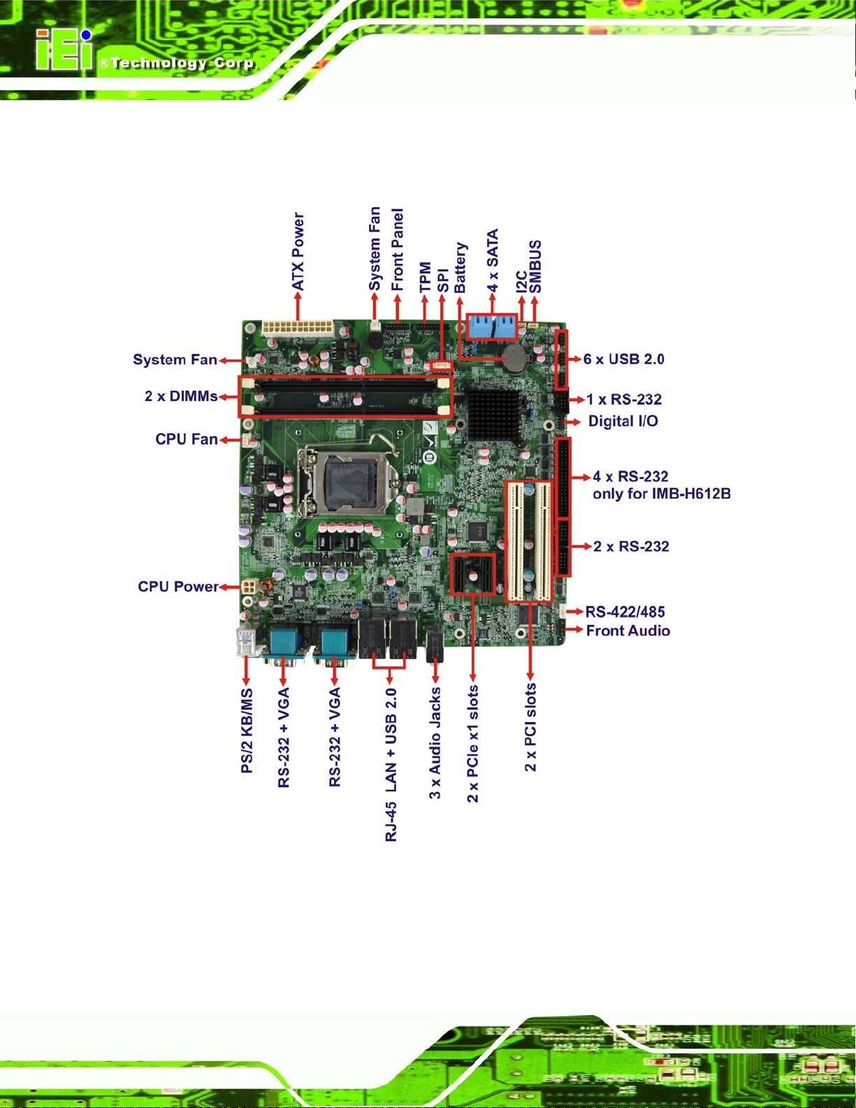
1.5 Connectors
The connectors on the IMB-H612 are shown in the figure below.
Figure 1-2: Connectors
Page 20

IMB-H612 Micro-ATX Motherboard
Page 5
1.6 Dimensions
The main dimensions of the IMB-H612 are shown in the diagram below.
Length: 244 mm
Width: 244 mm
Figure 1-3: IMB-H612 Dimensions (mm)
Page 21

IMB-H612 Mi c ro -ATX Motherboard
Page 6
1.7 Data Flow
Figure 1-4 shows the data flow between the system chipset, the CPU and other
components installed on the motherboard.
Figure 1-4: Data Flow Diagram
Page 22

IMB-H612 Micro-ATX Motherboard
Page 7
1.8 Technical Specifications
IMB-H612 technical specifications are listed below.
Specification/Model IMB-H612
Form Factor
CPU Supported
System Chipset
Graphics Engine
Memory
Audio
BIOS
Micro-ATX
LGA1 155 socket supports Intel® Core™ i7/i5/i3 quad/dual,
Pentium® dual, Celeron® dual/single core processor
Intel® H61
VGA1: Intel® HD Graphics 2000 / 3000 (Base on CPU type)
Support for DX10.1 and OpenGL 3.0
Full MPEG2, VC1, AVC Decode
Resolution supports up to 2048 x 1536 @75Hz
VGA2: Chrontel CH7317B
Resolution supports up to 1920 x 1200 @60Hz
Two 240-pin 1333/10 66 M Hz dual-channel unbuffered DDR3
SDRAM DIMMs supported ( system max. 16 GB)
Realtek ALC662 HD Audio codec (Line-in, Line-out, Mic)
UEFI BIOS
Digital I/O
Ethernet Controllers
Super I/O Controller
Watchdog Timer
Expansions
PCI
PCIe
I/O Interface Connectors
Audio Connectors
8-bit digital I/O, 4-bit input/4-bit output
Dual Realtek RTL8111E PCIe GbE controllers (LAN1 with ASF 2.0
support)
Fintek F81866
Software Programmable supports 1~255 sec system reset
Two PCI slots
Two PCIe x1 slots
Three external audio jack (Line-in, Line-out, Mic)
Page 23

IMB-H612 Mi c ro -ATX Motherboard
Page 8
Specification/Model IMB-H612
Display Port
Ethernet
Keyboard/Mouse
TPM
Front Audio
SMBus
I2C
CPU
Serial Ports
VGA1 integrated in Intel® H61
VGA2 integrated in Chront el CH731 7B
Two RJ-45 ports
One external PS/2 keyboard/mouse port
One 20-pin header
One 10-pin header
One 4-pin wafer
One 4-pin wafer
One 4-pin CPU fan connector
Two 3-pin system fan connectors
Two external RS-232 via DB-9 male connectors
Three RS-232 via internal 10-pin headers
Four RS-232 via internal 40-pin box headers for IMB-H612B
One RS-422/485 via internal 4-pin header
USB ports
Serial ATA
Environmental and Power Specifications
Power Supply
Power Consumption
Operating Temperature
Operating Humidity
Physical Specifications
Dimensions
Weight GW/NW
Table 1-2: IMB-H612 Specifications
Four external USB 2.0 ports by rear IO
Six internal USB 2.0 ports via three 8-pin headers
Four SATA 3Gb/s connectors
AT / ATX power supply supported
12V@0.27A, Vcore@5.3A, 5V@2.0A, 3.3V@1.0 A (Intel® 3.10GHz
Core™ I5-2400 with two 1333 MHz 4GB DDR3 DIMMs)
-10ºC ~ 60ºC
5% ~ 95% (non-condensing)
244 mm x 244 mm
1200 g / 680 g
Page 24

IMB-H612 Micro-ATX Motherboard
Page 9
Chapter
2
2 Packing List
Page 25

IMB-H612 Mi c ro -ATX Motherboard
Page 10
2.1 Anti-s tatic Precautions
WARNING!
Static electricity can destroy certain electronics. Make sure to follow the
ESD precautions to preve nt damage to the product, and injur y to the
user.
Make sure to adhere to the following guidelines:
Wear an anti-static wristband: Wearing an anti-static wrist ban d can prev ent
electrostatic discharge.
Self-grounding: Touch a grounded conductor every few minutes to discharge
any excess static buildup.
Use an anti-static pad: When configuring any circuit board, place it on an
anti-static mat.
Only handle the edges of the PCB: Don't touch the surface of the
motherboard. Hold the motherboard by the edges when handling.
2.2 Unpacking Precautions
When the IMB-H612 is unpacked, please do the following:
Follow the antistatic guidelines above.
Make sure the packing box is facing upwards when opening.
Make sure all the packing list items are present.
Page 26

IMB-H612 Micro-ATX Motherboard
Page 11
2.3 Packing List
NOTE:
If any of the components l isted in the checklist belo w are missing, do
not proceed with the installat ion. Cont act the I EI reseller or vendor the
IMB-H612 was purchas ed from or contact an IEI sales representative
directly by sending an email to sales@iei.com.tw.
The IMB-H612 is shipped with the following components:
Quantity Item and Part Number Ima g e
1 IMB-H612
4 SATA cable
(P/N: 32801-000703-200-RS)
1 I/O shielding
1 Mini jumper pack (2.54mm)
1 Utility CD
1 One Key Recovery CD
 Loading...