

Page 1
2012/3/62012/3/6
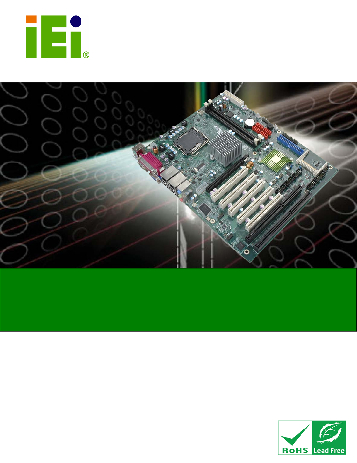
IMBA-G412ISA ATX Motherboard
Page i
MODEL:
ATX Motherboa rd for In tel® Core ™2 Du o/Quad CPU,
Rev. 2.00 – 6 March, 2012
IEI Technology Corp.
IMBA-G412ISA
800/1066/1333 MHz FSB, DDR3, VG A, LAN, SATA 3Gb/s,
PCIe x16, PCI, IS A, USB, HD Audio, RoHS Compliant
User Manual
Page 2
ii3/6/2012164
IMBA-G412ISA ATX Motherboard
Page ii
Date Version Changes
6 March, 2012 2.00 Update the version number
20 January, 2012 1.01 Update the BIOS section
26 October, 2010 1.00 Initial release
Revision
Page 3
2012/1/202012/1/20
IMBA-G412ISA ATX Motherboard
Page iii
COP YRIGHT NOTICE
The information in this document is subject to change without prior notice in order to
improve reliability, design and function and does not represent a commitment on the part
of the manufacturer.
In no event will the manufacturer be liable for direct, indirect, special, incidental, or
consequential damages arising out of the use or inability to use the product or
documentation, even if advised of the possibilit y of such damages.
This document contains proprietary information protected by copyright. All rights are
Copyright
reserved. No part of this manual may be reproduced by any mechanical, electronic, or
other means in any form without prior written perm ission of the manufacturer.
TRADEMARKS
All registered trademarks and product names mentioned herein are used for identification
purposes only and may be trademarks and/or registered trademarks of their respective
owners.
Page 4
iv1/20/2012164
IMBA-G412ISA ATX Motherboard
Page iv
Table of Contents
1 INTRODUCTION .......................................................................................................... 1
1.1 INTRODUCTION ........................................................................................................... 2
1.2 BENEFITS ................................................................................................................... 2
1.3 FEATURES ................................................................................................................... 3
1.4 CONNECTORS ............................................................................................................. 4
1.5 DIMENSIONS ............................................................................................................... 5
1.6 DATA FLOW ................................................................................................................ 6
1.7 TECHNICAL SPECIFICATIONS ...................................................................................... 7
2 PACKING LIST ........................................................................................................... 10
2.1 ANTI-STATIC PRECAUTIONS ....................................................................................... 11
2.2 UNPACKING PRECAUTIONS ........................................................................................ 11
2.3 PACKING LIST ........................................................................................................... 12
2.4 OPTIONAL ITEMS ...................................................................................................... 13
3 CONNECTORS ........................................................................................................... 15
3.1 PERIPHERAL INTERFACE CONNECTORS ..................................................................... 16
3.1.1 Layout .............................................................................................................. 16
3.1.2 Peripheral Interface Connectors ..................................................................... 17
3.1.3 External Interface Panel Connectors ............................................................... 18
3.2 INTERNAL PERIPHERAL CONNECTORS ...................................................................... 18
3.2.1 Audio Connector .............................................................................................. 18
3.2.2 CPU Fan Connector ........................................................................................ 19
3.2.3 System Fan Connectors .................................................................................... 20
3.2.4 CPU Power Input Connector ........................................................................... 21
3.2.5 Digital I/O Connector ...................................................................................... 22
3.2.6 Front Panel Connector .................................................................................... 22
3.2.7 IDE Connector ................................................................................................. 23
3.2.8 Infrared Interface Connector ........................................................................... 25
3.2.9 Memory Slot ..................................................................................................... 25
3.2.10 PCIe Power Input Connector ......................................................................... 26
Page 5

2012/1/202012/1/20
IMBA-G412ISA ATX Motherboard
Page v
3.2.11 Power Connector ............................................................................................ 27
3.2.12 RS-232 Serial Port Connectors ...................................................................... 28
3.2.13 RS-232/422/485 Serial Port Connector ......................................................... 29
3.2.14 SATA Drive Connectors ................................................................................. 30
3.2.15 SMBus Connector .......................................................................................... 30
3.2.16 SPI Flash Connector ...................................................................................... 31
3.2.17 TPM Connector .............................................................................................. 32
3.2.18 USB Connectors ............................................................................................. 33
3.3 EXTERNAL PERIPHERAL INTERFACE CONNECTOR PANEL ......................................... 34
3.3.1 Audio Connectors ............................................................................................. 35
3.3.2 Keyboard/Mouse Connector ............................................................................ 35
3.3.3 LAN Connectors ............................................................................................... 36
3.3.4 Parallel Port Connector .................................................................................. 37
3.3.5 Serial Port Connector (COM1) ....................................................................... 38
3.3.6 USB Connectors ............................................................................................... 39
3.3.7 VGA Connector ................................................................................................ 39
4 INSTALLATION ......................................................................................................... 41
4.1 ANTI-STATIC PRECAUTIONS ...................................................................................... 42
4.2 INSTALLATION CONSIDERATIONS .............................................................................. 42
4.3 BASIC INSTALLATION ............................................................................................... 44
4.3.1 CPU Installation .............................................................................................. 44
4.3.2 Cooling Kit Installation ................................................................................... 47
4.3.3 DIMM Installation ........................................................................................... 49
4.3.4 Motherboard Installation ................................................................................. 49
4.4 JUMPER SETTINGS .................................................................................................... 50
4.4.1 AT/ATX Power Select Jumpers ........................................................................ 50
4.4.2 Clear CMOS Jumper ........................................................................................ 51
4.4.3 COM 2 Function Select Jumper ....................................................................... 52
4.4.4 CompactFlash® Setup ..................................................................................... 53
4.4.5 CF Voltage Select Jumper ................................................................................ 53
4.4.6 USB Power Select Jumpers .............................................................................. 54
4.5 INTERNAL PERIPHERAL DEVICE CONNECTIONS ........................................................ 55
4.5.1 SATA Drive Connection ................................................................................... 55
4.5.2 Dual RS-232 Cable with Slot Bracket .............................................................. 57
Page 6
vi1/20/2012164
IMBA-G412ISA ATX Motherboard
Page vi
4.6 EXTERNAL PERIPHERAL INTERFACE CONNECTION ................................................... 58
4.6.1 Audio Connector .............................................................................................. 58
4.6.2 PS/2 Keyboard and Mouse Connection ........................................................... 59
4.6.3 LAN Connection ............................................................................................... 60
4.6.4 Parallel Device Connection ............................................................................. 61
4.6.5 Serial Device Connection ................................................................................ 62
4.6.6 USB Device Connection ................................................................................... 63
4.6.7 VGA Monitor Connection ................................................................................ 64
4.7 SOFTWARE INSTALLATION ........................................................................................ 65
5 BIOS .............................................................................................................................. 66
5.1 INTRODUCTION ......................................................................................................... 67
5.1.1 Starting Setup ................................................................................................... 67
5.1.2 Using Setup ...................................................................................................... 67
5.1.3 Getting Help ..................................................................................................... 68
5.1.4 Unable to Reboot after Configuration Changes .............................................. 68
5.1.5 BIOS Menu Bar ................................................................................................ 68
5.2 MAIN ........................................................................................................................ 69
5.3 ADVANCED ............................................................................................................... 70
5.3.1 CPU Configuration .......................................................................................... 71
5.3.2 IDE Configuration ........................................................................................... 71
5.3.2.1 IDE Master, IDE Slave ............................................................................. 73
5.3.3 Super IO Configuration ................................................................................... 79
5.3.4 Hardware Health Configuration ...................................................................... 83
5.3.5 Power Configuration ....................................................................................... 86
5.3.5.1 ACPI configuration ................................................................................... 87
5.3.6 Remote Access Configuration .......................................................................... 88
5.3.7 USB Configuration ........................................................................................... 91
5.3.8 Trusted Computing ........................................................................................... 93
5.4 PCI/PNP ................................................................................................................... 94
5.5 BOOT ........................................................................................................................ 96
5.5.1 Boot Settings Configuration ............................................................................. 96
5.6 SECURITY ................................................................................................................. 98
5.7 CHIPSET ................................................................................................................. 100
5.7.1 North Bridge Chipset Configuration ............................................................. 100
Page 7
2012/1/202012/1/20
IMBA-G412ISA ATX Motherboard
Page vii
5.7.2 South Bridge Chipset Configuration .............................................................. 102
5.8 EXIT ....................................................................................................................... 104
A BIOS OPTIONS ........................................................................................................ 106
B TERMINOLOGY ....................................................................................................... 110
C ONE KEY RECOVERY ............................................................................................ 114
C.1 ONE KEY RECOVERY INTRODUCTION ..................................................................... 115
C.1.1 System Requirement ....................................................................................... 116
C.1.2 Supported Operating System .......................................................................... 117
C.2 SETUP PROCEDURE FOR WINDOWS ......................................................................... 118
C.2.1 Hardware and BIOS Setup ............................................................................. 118
C.2.2 Create Partitions ............................................................................................ 119
C.2.3 Install Operating System, Drivers and Applications ..................................... 122
C.2.4 Build-up Recovery Partition .......................................................................... 123
C.2.5 Create Factory Default Image ...................................................................... 125
C.3 SETUP PROCEDURE FOR LINUX .............................................................................. 130
C.4 RECOVERY TOOL FUNCTIONS ................................................................................ 133
C.4.1 Factory Restore ............................................................................................. 135
C.4.2 Backup System ............................................................................................... 136
C.4.3 Restore Your Last Backup .............................................................................. 137
C.4.4 Manual .......................................................................................................... 138
C.5 OTHER INFORMATION ............................................................................................ 139
C.5.1 Using AHCI Mode or ALi M5283 / VIA VT6421A Controller ...................... 139
C.5.2 System Memory Requirement ........................................................................ 141
D WA TCHDOG TIMER .............................................................................................. 142
E DIGITAL I/O INTERFACE ..................................................................................... 145
E.1 INTRODUCTION ...................................................................................................... 146
E.2 DIO CONNECTOR PINOUTS .................................................................................... 146
E.3 ASSEMBLY LANGUAGE EXAMPLE .......................................................................... 146
F HAZARDOUS MATERIALS DISCLOSURE ........................................................ 147
F.1 HAZARDOUS MATERIALS DISCLOSURE TABLE FOR IPB PRODUCTS CERTIFIED AS
ROHS COMPLIANT UNDER 2002/95/EC WITHOUT MERCURY ..................................... 148
Page 8
viii1/20/2012164
IMBA-G412ISA ATX Motherboard
Page viii
List of Figures
Figure 1-1: IMBA-G412ISA ............................................................................................................. 2
Figure 1-2: Connectors
Figure 1-3: Dimensions (mm)
Figure 1-4: Data Flow Diagram
Figure 3-1: Connectors and Jumpers
Figure 3-2: Audio Connector Location
Figure 3-3: CPU Fan Connector Location
Figure 3-4: System Fan Connector Locations
Figure 3-5: CPU Power Input Connector Location
Figure 3-6: Digital I/O Connector Location
Figure 3-7: Front Panel Connector Location
Figure 3-8: IDE Connector Location
Figure 3-9: Infrared Connector Location
Figure 3-10: Memory Card Slot Location
Figure 3-11: PCIe Power Input Connector Location
Figure 3-12: Power Connector Location
Figure 3-13: Serial Port Connector Locations
Figure 3-14: RS-232/422/485 Serial Port Connector L ocation
.................................................................................................................. 4
........................................................................................................ 5
...................................................................................................... 6
......................................................................................... 16
....................................................................................... 19
.................................................................................. 20
........................................................................... 20
.................................................................... 21
................................................................................ 22
............................................................................. 23
........................................................................................... 24
.................................................................................... 25
................................................................................... 26
................................................................. 26
.................................................................................... 27
........................................................................... 28
.................................................. 29
Figure 3-15: SATA Drive Connector Location
Figure 3-16: SMBus Connector Locations
Figure 3-17: SPI Flash Connector
Figure 3-18: TPM Connector Pinout Location
Figure 3-19: USB Connector Pinout Locations ......................................................................... 34
Figure 3-20: External Peripheral Interface Connector
Figure 3-21: Audio Connector
Figure 3-22: PS/2 Pinout and Configuration
Figure 3-23: Parallel Port Connector Location
Figure 3-24: Serial Port Pinouts
Figure 3-25: VGA Connector
Figure 4-1: Intel LGA775 Socket
........................................................................... 30
................................................................................. 31
............................................................................................... 32
........................................................................... 33
.............................................................. 34
..................................................................................................... 35
.............................................................................. 36
.......................................................................... 38
.................................................................................................. 38
....................................................................................................... 39
................................................................................................. 44
Page 9

2012/1/202012/1/20
IMBA-G412ISA ATX Motherboard
Page ix
Figure 4-2: Remove Protective Cover ......................................................................................... 45
Figure 4-3: CPU Socket Load Plate
Figure 4-4: Insert the Socket LGA775 CPU
Figure 4-5: Cooling Kits
Figure 4-6: Securing the Heat sink to the IMBA-G412ISA
Figure 4-7: DIMM Installation
Figure 4-8: AT/ATX Power Select Jumper Location
Figure 4-9: Clear BIOS Jumper Location
Figure 4-10: COM 2 Function Select Jumper Location
Figure 4-11: CompactFlash® Setup Jumper Location
Figure 4-12: LCD Voltage Selection Jumper Location
Figure 4-13: USB Power Select Jumper Location
Figure 4-14: SATA Drive Cable Connection
Figure 4-15: SATA Power Drive Connection
Figure 4-16: Dual RS-232 Cable Installation
Figure 4-17: Audio Connector
Figure 4-18: PS/2 Keyboard/Mouse Connector
Figure 4-19: LAN Connection
............................................................................................. 45
................................................................................ 46
............................................................................................................... 47
........................................................ 48
....................................................................................................... 49
.................................................................. 51
................................................................................... 52
............................................................. 52
............................................................. 53
.............................................................. 54
..................................................................... 55
............................................................................... 56
.............................................................................. 57
.............................................................................. 58
..................................................................................................... 59
......................................................................... 60
...................................................................................................... 61
Figure 4-20: Parallel Device Connector
Figure 4-21: Serial Device Connector
Figure 4-22: USB Connector
Figure 4-23: VGA Connector
Figure C-1: IEI One Key Recovery Tool Menu .........................................................................115
Figure C-2: Launching the Recovery Tool
Figure C-3: Recovery Tool Setup Menu
Figure C-4: Command Mode
Figure C-5: Partition Creation Commands
Figure C-6: Launching the Recovery Tool
Figure C-7: System Configuration for Windows
Figure C-8: Build-up Recovery Partition
Figure C-9: Press any key to continue
Figure C-10: Press F3 to Boot into Recovery Mode
Figure C-11: Recovery Tool Menu
Figure C-12: About Symantec Ghost Window
Figure C-13: Symantec Ghost Path
...................................................................................... 62
......................................................................................... 63
........................................................................................................ 64
....................................................................................................... 65
...............................................................................119
...................................................................................120
......................................................................................................120
...............................................................................121
...............................................................................123
.....................................................................123
..................................................................................124
.....................................................................................124
................................................................125
............................................................................................125
.........................................................................126
..........................................................................................126
Page 10

x1/20/2012164
IMBA-G412ISA ATX Motherboard
Page x
Figure C-14: Select a Local Source Drive ................................................................................127
Figure C-15: Select a Source Partition from Basi c Drive
Figure C-16: File Name to Copy Image to
Figure C-17: Compress Image
Figure C-18: Image Creation Confirmation
Figure C-19: Image Creation Complete
Figure C-20: Image Creation Complete
Figure C-21: Press Any Key to Continue
Figure C-22: Partitions for Linux
Figure C-23: System Configuration for Linux
Figure C-24: Access menu.lst in Linux (Text Mode )
Figure C-25: Recovery Tool Menu
Figure C-26: Recovery Tool Main Menu
Figure C-27: Restore Factory Default
Figure C-28: Recovery Complete Window
Figure C-29: Backup System
Figure C-30: System Backup Complete Window
Figure C-31: Restore Backup
.......................................................127
................................................................................128
...................................................................................................128
..............................................................................129
....................................................................................129
....................................................................................129
.................................................................................130
...............................................................................................131
..........................................................................132
...............................................................132
............................................................................................133
...................................................................................134
.......................................................................................135
...............................................................................135
.....................................................................................................136
....................................................................136
....................................................................................................137
Figure C-32: Restore System Backup Complete Window
Figure C-33: Symantec Ghost Window
......................................................137
....................................................................................138
Page 11

2012/1/202012/1/20
IMBA-G412ISA ATX Motherboard
Page xi
List of Tables
Table 1-1: Technical Specifications .............................................................................................. 9
Table 2-1: Packing List
Table 2-2: Optional Items
Table 3–1: Internal Peripheral Connectors
Table 3–2: External Peripheral Connectors
Table 3-3: Audio Connector Pinouts
Table 3-4: CPU Fan Connector Pinouts
Table 3-5: System Fan Connector Pinouts (SYS_FAN1)
Table 3-6: System Fan Connector Pinouts (SYS_FAN2 and SYS_FAN3)
Table 3-7: CPU Power Input Connector Pinouts
Table 3-8: Digital I/O Connector Pinouts
Table 3-9: Front Panel Connector Pinouts
Table 3-10: IDE Connector Pinouts
Table 3-11: Infrared Connector Pinouts
Table 3-12: PCIe Power Input Connector Pinouts
Table 3-13: Power Connector Pinouts
Table 3-14: Serial Port Connector Pinouts
Table 3-15: RS-232/422/485 Serial Port Connector Pinouts
................................................................................................................. 13
............................................................................................................. 14
................................................................................ 18
............................................................................... 18
.......................................................................................... 19
...................................................................................... 20
.......................................................... 21
............................... 21
....................................................................... 21
.................................................................................... 22
................................................................................. 23
............................................................................................. 24
..................................................................................... 25
..................................................................... 27
........................................................................................ 28
................................................................................ 29
..................................................... 30
Table 3-16: SMBus Connector Pinouts
Table 3-17: SPI Flash Connector
Table 3-18: TPM Connector Pinouts
Table 3-19: USB Port Connector Pinouts
Table 3-20: Keyboard Connector Pinouts
Table 3-21: LAN Pinouts
Table 3-22: Parallel Port Connector Pinouts
Table 3-23: Serial Port Pinouts
Table 3-24: USB Port Pinouts
Table 3-25: VGA Connector Pinouts
Table 4-1: Jumpers
Table 4-2: AT/ATX Power Select Jumper Settings
...................................................................................... 31
................................................................................................. 32
........................................................................................... 33
................................................................................... 34
.................................................................................. 36
.............................................................................................................. 37
............................................................................. 37
.................................................................................................... 38
...................................................................................................... 39
........................................................................................... 40
....................................................................................................................... 50
.................................................................... 51
Page 12

xii1/20/2012164
IMBA-G412ISA ATX Motherboard
Page xii
Table 4-3: Clear BIOS Jumper Settings ...................................................................................... 51
Table 4-4: COM 2 Function Select Jumper Settings
Table 4-5: CompactFlash® Setup Jumper Settings
Table 4-6: LCD Voltage Selection Jumper Settings
Table 4-7: USB Power Select Jumper Settings
Table 5-1: BIOS Navigation Keys
................................................................. 52
.................................................................. 53
.................................................................. 54
......................................................................... 54
................................................................................................ 68
Page 13

2012/1/202012/1/20
IMBA-G412ISA ATX Motherboard
Page xiii
BIOS Menus
BIOS Menu 1: Main ....................................................................................................................... 69
BIOS Menu 2: Advanced
BIOS Menu 3: CPU Configuration
BIOS Menu 4: IDE
BIOS Menu 5: IDE Master and IDE Slave Configuration
BIOS Menu 6: Super IO Configuration
BIOS Menu 7: Hardware Health Configuration
BIOS Menu 8: Power Configuration
BIOS Menu 9: ACPI Configuration
BIOS Menu 10: Remote Access Configuration
BIOS Menu 11: USB Configuration
BIOS Menu 12: Trusted Computing
BIOS Menu 13: PCI/PnP Configuration
BIOS Menu 14: Boot
BIOS Menu 15: Boot Settings Configuration
BIOS Menu 16: Security
BIOS Menu 17: Chipset
BIOS Menu 18: North Bridge Chipset Configuration
Configuration ................................................................................................. 72
.............................................................................................................. 70
............................................................................................... 71
........................................................... 74
........................................................................................ 79
.......................................................................... 84
............................................................................................ 87
.............................................................................................. 88
.......................................................................... 89
............................................................................................. 92
............................................................................................ 93
....................................................................................... 94
..................................................................................................................... 96
............................................................................. 97
............................................................................................................... 99
..............................................................................................................100
..............................................................101
BIOS Menu 19: South Bridge Chipset Configuration
BIOS Menu 20: Exit
..............................................................102
.....................................................................................................................104
Page 14

Page 15

2012/1/202012/1/20
IMBA-G412ISA ATX Motherboard
Page 1
Chapter
1
1 Introduction
Page 16

21/20/2012164
Page 2
IMBA-G412ISA ATX Motherboard
1.1 Introduction
Figure 1-1: IMBA-G412ISA
The IMBA-G412ISA is an ATX motherboard with an 800/1066/1333 MHz front side bus.
The LGA775 socket accepts Intel® Core™2 Duo/Quad processors and the motherboard
supports two DDR3 DIMMs up to 4.0 GB each (8.0 GB total). The IMBA-G412ISA
includes VGA output with up to QXGA resolution. Multiple expansion cards may be added,
including PCIe x16, PCI and ISA interface. Other features include four SATA 3Gb/s, dual
PCIe GbE, digital I/O, five RS-232 serial ports, one RS-232/422/485 serial ports, one
parallel port, audio jacks and eight USB ports.
1.2 Benefits
Some of the IMBA-G412ISA motherboard benefits include:
Powerful graphics
Staying connected with both wired LAN connections
Speedy running of multiple programs and applications
Multiple expansion capabilities
Page 17

2012/1/202012/1/20
IMBA-G412ISA ATX Motherboard
Page 3
1.3 Features
Some of the IMBA-G412ISA motherboard features are li st ed below:
ATX form factor
RoHS compliant
LGA775 CPU socket
Supports two DDR3 DIMMs
Supports dual display by VGA port and an optional PCIe x16 SDVO
expansion card
Two Gigabit Ethernet connectors
Four SATA connectors
Eight USB ports
Six serial ports
Supports PCI and ISA expansion cards with following combinations
o Five PCI cards and one ISA card
o Four PCI cards and two ISA cards
Page 18

41/20/2012164
Page 4
IMBA-G412ISA ATX Motherboard
1.4 Connectors
The connectors on the IMBA-G412ISA are shown in the f i gure below.
Figure 1-2: Connectors
Page 19

2012/1/202012/1/20
IMBA-G412ISA ATX Motherboard
Page 5
1.5 Dimensions
The main dimensions of the IMBA-G412ISA are shown in the diagram below.
Figure 1-3: Dimensions (mm)
Page 20

61/20/2012164
Page 6
IMBA-G412ISA ATX Motherboard
1.6 Data Flow
Figure 1-4 shows the data flow between the system chipset, the CPU and other
components installed on the motherboard.
Figure 1-4: Data Flow Diagram
Page 21

2012/1/202012/1/20
IMBA-G412ISA ATX Motherboard
Page 7
1.7 Technical Specifications
IMBA-G412ISA technical specifications are shown below.
Specifications IMBA-G412ISA
Form Factor
CPU Supported
Front Side Bus (FSB)
Northbridge Chipset
Mem ory
Graphic Engine
Integrated Graphics
Southbridge Chipset
BIOS
Digital I/O
Etherne t Contro llers
ATX
Socket LGA775 Intel® Core™2 Duo/Quad, Pentium® D or
Celeron® processor
800/1066/1333 MHz
Intel® G41
Two 240-pin 800/1066 MHz dual-channel DDR3 SDRAM
DIMMs (system max. 4 GB)
Intel® GMA X4500
VGA integrated in Intel® G41 supports up to
2048 x 1536 @ 75 MHz
Intel® ICH7
UEFI BIOS
8-bit, 4-bit input/4-bit output
Two Realtek RTL8111E PCIe GbE controllers
Audio
Super I/O Controller
Watchdog Timer
ISA Bridge
Expansion
(LAN1 with ASF2.0 support)
Realtek ALC888 HD Audio codec
Fintek F81865
Software programmable supports 1~255 sec. system reset
ITE IT8888
One PCIe x16 socket
Four PCI sockets
One ISA socket
One PCI/ISA socket
Page 22

81/20/2012164
Page 8
IMBA-G412ISA ATX Motherboard
I/O In terf a c e
Audio Jack
Fan connector
Keyboard/Mouse
Serial Port s
USB 2.0/1.1 ports
Infrared
Parallel Po rt
Serial ATA
One line-in
One line-out
One mic-in
One 4-pin wafer for CPU fan
Three 3-pin wafer for system fans
Two external PS/2 connectors
Five RS-232 COM connectors
One RS-232/422/485 COM connector
Four internal via pin header
Four external USB ports
One infrared connector via 5-pin header
One external parallel port
Four independent SATA channels with 3.0 Gb/s data
transfer rates
IDE
CompactFlash®
SMBu s
TPM
Environmental and Power Specifications
Power Supply
Power Consumption
Operating temperature
Humidity
One 40-pin IDE connector
One CF Type II slot
One 4-pin wafer SMBus connector
One TPM module connector via 20-pin header
ATX power supported
5 V @ 5.06 A
12 V @ 2.01 A
3.3 V @ 0.15 A
-12 V @ 0.05 A
(2.8 GHz Intel® Core™2 Duo E7400 with two 1 GB
1066 MHz DDR3 DIMMs)
-10ºC ~ 60ºC, requires cooler and silicone heat sink paste
5% ~ 95% (non-condensing)
Page 23

2012/1/202012/1/20
IMBA-G412ISA ATX Motherboard
Page 9
Phys ical Specific atio ns
Dimensions
Weight (Gross/Net)
Table 1-1: Technical Specifications
305 mm x 244 mm
1200 g / 750 g
Page 24

101/20/2012164
Page 10
IMBA-G412ISA ATX Motherboard
Chapter
2
2 Packing List
Page 25

2012/1/202012/1/20
IMBA-G412ISA ATX Motherboard
Page 11
2.1 Anti-static Precautions
WARNING!
Static electricity can destroy certain electronics. Make sure to follow the
ESD precautions to prevent damage to the product, and injury to the
user.
Make sure to adhere to the following guidelines:
Wear an anti-static wristband: Wearing an anti-static wristband can prevent
electrostatic discharge.
Self-grounding: Touch a grounded conductor every few mi nutes to dis charge
any excess static buildup.
Use an anti-static pad: When configuring any circuit board, place it on an
anti-static mat.
Only handle the edges of the PCB: Don't touch t he surface of the
motherboard. Hold the motherboard by the edges when handling.
2.2 Unpacking Precautions
When the IMBA-G412ISA is unpacked, please do the following:
Follow the antistatic guidelines above.
Make sure the packing box is facing upwards when opening.
Make sure all the packing list items are present.
Page 26

121/20/2012164
Page 12
IMBA-G412ISA ATX Motherboard
was purchased from or contact an IEI sales
2.3 Packing List
NOTE:
If any of the components listed in the checklist below are missing, do
not proceed with the installation. Contact the IEI reseller or vendor the
IMBA-G412ISA
representative directly by sending an email to sales@iei.com.tw.
The IMBA-G412ISA is shipped with the following components:
Quantity Item and Part Number Ima g e
1 IMBA-G412ISA SBC
4 SATA cable
(P/N: 32000-062800-RS)
1 Dual RS-232 cable
(P/N: 19800-000051-RS)
1 Mini jumper pack (2.54mm)
(P/N:33100-000079-RS)
1 I/O shielding
(P/N:45014-0017C0-00-RS)
 Loading...