

Page 1
KINO-G410 Mini-ITX Motherboard
IEI Technology Corp.
MODEL:
KINO-G410
Mini-ITX Motherboard for Intel® Core™2 Duo/Quad/Extreme
CPU, 800/1066/1333 MHz FSB, DDR3, VGA, LAN, SATA 3Gb/s,
PCIe x16, USB, HD Audio, RoHS Compliant
User Manual
Rev. 1.03 – 2 February, 2012
Page i
Page 2
KINO-G410 Mini-ITX Motherboard
Revision
Date Version Changes
2 February, 2012 1.03 Modified Section 3.3.2
17 August, 2011 1.02 Modified Figure 4-9
4 March, 2011 1.01 Modified VGA to LVDS connector pinouts (Table 3-16)
13 September, 2010 1.00 Initial release
Page ii
Page 3

KINO-G410 Mini-ITX Motherboard
COPYRIGHT NOTICE
The information in this document is subject to change without prior notice in order to
improve reliability, design and function and does not represent a commitment on the part
of the manufacturer.
In no event will the manufacturer be liable for direct, indirect, special, incidental, or
consequential damages arising out of the use or inability to use the product or
documentation, even if advised of the possibility of such damages.
This document contains proprietary information protected by copyright. All rights are
Copyright
reserved. No part of this manual may be reproduced by any mechanical, electronic, or
other means in any form without prior written permission of the manufacturer.
TRADEMARKS
All registered trademarks and product names mentioned herein are used for identification
purposes only and may be trademarks and/or registered trademarks of their respective
owners.
Page iii
Page 4
KINO-G410 Mini-ITX Motherboard
Table of Contents
1 INTRODUCTION.......................................................................................................... 1
1.1 INTRODUCTION........................................................................................................... 2
1.2 BENEFITS ................................................................................................................... 2
1.3 FEATURES................................................................................................................... 2
1.4 CONNECTORS ............................................................................................................. 3
1.5 DIMENSIONS............................................................................................................... 4
1.6 DATA FLOW................................................................................................................ 5
1.7 TECHNICAL SPECIFICATIONS ...................................................................................... 6
2 PACKING LIST............................................................................................................. 8
2.1 ANTI-STATIC PRECAUTIONS........................................................................................ 9
2.2 UNPACKING PRECAUTIONS......................................................................................... 9
2.3 PACKING LIST........................................................................................................... 10
2.4 OPTIONAL ITEMS.......................................................................................................11
3 CONNECTORS ........................................................................................................... 13
3.1 PERIPHERAL INTERFACE CONNECTORS..................................................................... 14
3.1.1 Layout .............................................................................................................. 14
3.1.2 Peripheral Interface Connectors ..................................................................... 15
3.1.3 External Interface Panel Connectors............................................................... 15
3.2 INTERNAL PERIPHERAL CONNECTORS ...................................................................... 16
3.2.1 Battery Connector............................................................................................ 16
3.2.2 CPU Fan Connector........................................................................................ 17
3.2.3 System Fan Connector..................................................................................... 18
3.2.4 CPU Power Input Connector........................................................................... 18
3.2.5 Digital I/O Connector...................................................................................... 19
3.2.6 Front Panel Connector.................................................................................... 20
3.2.7 Memory Slot..................................................................................................... 21
3.2.8 Parallel Port Connector .................................................................................. 21
3.2.9 Power Connector............................................................................................. 23
3.2.10 RS-232 Serial Port Connector....................................................................... 24
Page iv
Page 5

KINO-G410 Mini-ITX Motherboard
3.2.11 RS-232/422/485 Serial Port Connector ......................................................... 25
3.2.12 SATA Drive Connectors ................................................................................. 26
3.2.13 SMBus Connector .......................................................................................... 26
3.2.14 SPI Flash Connector...................................................................................... 27
3.2.15 USB Connectors............................................................................................. 28
3.2.16 VGA to LVDS Connector................................................................................ 29
3.3 EXTERNAL PERIPHERAL INTERFACE CONNECTOR PANEL ......................................... 30
3.3.1 Audio Connector .............................................................................................. 30
3.3.2 Keyboard/Mouse Connector............................................................................ 31
3.3.3 LAN Connector ................................................................................................ 32
3.3.4 Serial Port Connectors (COM1, COM2 and COM3)...................................... 32
3.3.5 USB Connector ................................................................................................ 33
3.3.6 VGA Connector................................................................................................ 33
4 INSTALLATION ......................................................................................................... 35
4.1 ANTI-STATIC PRECAUTIONS...................................................................................... 36
4.2 INSTALLATION CONSIDERATIONS.............................................................................. 36
4.3 BASIC INSTALLATION ............................................................................................... 38
4.3.1 CPU Installation.............................................................................................. 38
4.3.2 Cooling Kit Installation ................................................................................... 41
4.3.3 DIMM Installation........................................................................................... 43
4.3.4 Motherboard Installation................................................................................. 43
4.4 JUMPER SETTINGS .................................................................................................... 44
4.4.1 Clear CMOS Jumper........................................................................................ 44
4.4.2 COM 6 Function Select Jumper....................................................................... 45
4.5 INTERNAL PERIPHERAL DEVICE CONNECTIONS........................................................ 46
4.5.1 SATA Drive Connection ................................................................................... 46
4.5.2 USB Cable (Dual Port) with Slot Bracket ....................................................... 48
4.6 EXTERNAL PERIPHERAL INTERFACE CONNECTION................................................... 49
4.6.1 Audio Connector .............................................................................................. 49
4.6.2 PS/2 Keyboard and Mouse Connection........................................................... 50
4.6.3 LAN Connection............................................................................................... 51
4.6.4 Serial Device Connection ................................................................................ 52
4.6.5 USB Device Connection................................................................................... 53
4.6.6 VGA Monitor Connection ................................................................................ 54
Page v
Page 6

4.7 SOFTWARE INSTALLATION ........................................................................................ 55
5 BIOS.............................................................................................................................. 56
5.1 INTRODUCTION......................................................................................................... 57
5.1.1 Starting Setup................................................................................................... 57
5.1.2 Using Setup...................................................................................................... 57
5.1.3 Getting Help..................................................................................................... 58
5.1.4 Unable to Reboot after Configuration Changes.............................................. 58
5.1.5 BIOS Menu Bar................................................................................................ 58
5.2 MAIN........................................................................................................................ 59
5.3 ADVANCED............................................................................................................... 60
5.3.1 CPU Configuration.......................................................................................... 61
5.3.2 IDE Configuration........................................................................................... 62
5.3.2.1 IDE Master, IDE Slave............................................................................. 63
5.3.3 Super IO Configuration ................................................................................... 67
KINO-G410 Mini-ITX Motherboard
5.3.4 Hardware Health Configuration...................................................................... 73
5.3.5 Power Configuration ....................................................................................... 75
5.3.5.1 ACPI Settings............................................................................................ 76
5.3.6 Remote Access Configuration.......................................................................... 76
5.3.7 USB Configuration........................................................................................... 79
5.4 PCI/PNP................................................................................................................... 81
5.5 BOOT........................................................................................................................ 84
5.5.1 Boot Settings Configuration............................................................................. 84
5.6 SECURITY................................................................................................................. 86
5.7 CHIPSET ................................................................................................................... 87
5.7.1 North Bridge Configuration............................................................................. 88
5.7.2 South Bridge Configuration............................................................................. 89
5.8 EXIT......................................................................................................................... 91
A BIOS OPTIONS .......................................................................................................... 93
B TERMINOLOGY........................................................................................................ 96
C ONE KEY RECOVERY........................................................................................... 100
C.1 ONE KEY RECOVERY INTRODUCTION .................................................................... 101
C.1.1 System Requirement ...................................................................................... 102
C.1.2 Supported Operating System......................................................................... 103
Page vi
Page 7

KINO-G410 Mini-ITX Motherboard
C.2 SETUP PROCEDURE FOR WINDOWS........................................................................ 104
C.2.1 Hardware and BIOS Setup ............................................................................ 104
C.2.2 Create Partitions........................................................................................... 105
C.2.3 Install Operating System, Drivers and Applications..................................... 108
C.2.4 Build-up Recovery Partition.......................................................................... 109
C.2.5 Create Factory Default Image .......................................................................111
C.3 SETUP PROCEDURE FOR LINUX...............................................................................116
C.4 RECOVERY TOOL FUNCTIONS .................................................................................119
C.4.1 Factory Restore............................................................................................. 121
C.4.2 Backup System............................................................................................... 122
C.4.3 Restore Your Last Backup.............................................................................. 123
C.4.4 Manual .......................................................................................................... 124
C.5 OTHER INFORMATION............................................................................................ 125
C.5.1 Using AHCI Mode or ALi M5283 / VIA VT6421A Controller ...................... 125
C.5.2 System Memory Requirement........................................................................ 127
D WATCHDOG TIMER.............................................................................................. 128
E DIGITAL I/O INTERFACE..................................................................................... 131
E.1 INTRODUCTION ...................................................................................................... 132
E.2 DIO CONNECTOR PINOUTS.................................................................................... 132
E.3 ASSEMBLY LANGUAGE EXAMPLE .......................................................................... 132
F HAZARDOUS MATERIALS DISCLOSURE........................................................ 133
F.1 HAZARDOUS MATERIALS DISCLOSURE TABLE FOR IPB PRODUCTS CERTIFIED AS
ROHS COMPLIANT UNDER 2002/95/EC WITHOUT MERCURY ..................................... 134
Page vii
Page 8

KINO-G410 Mini-ITX Motherboard
List of Figures
Figure 1-1: KINO-G410 ...................................................................................................................2
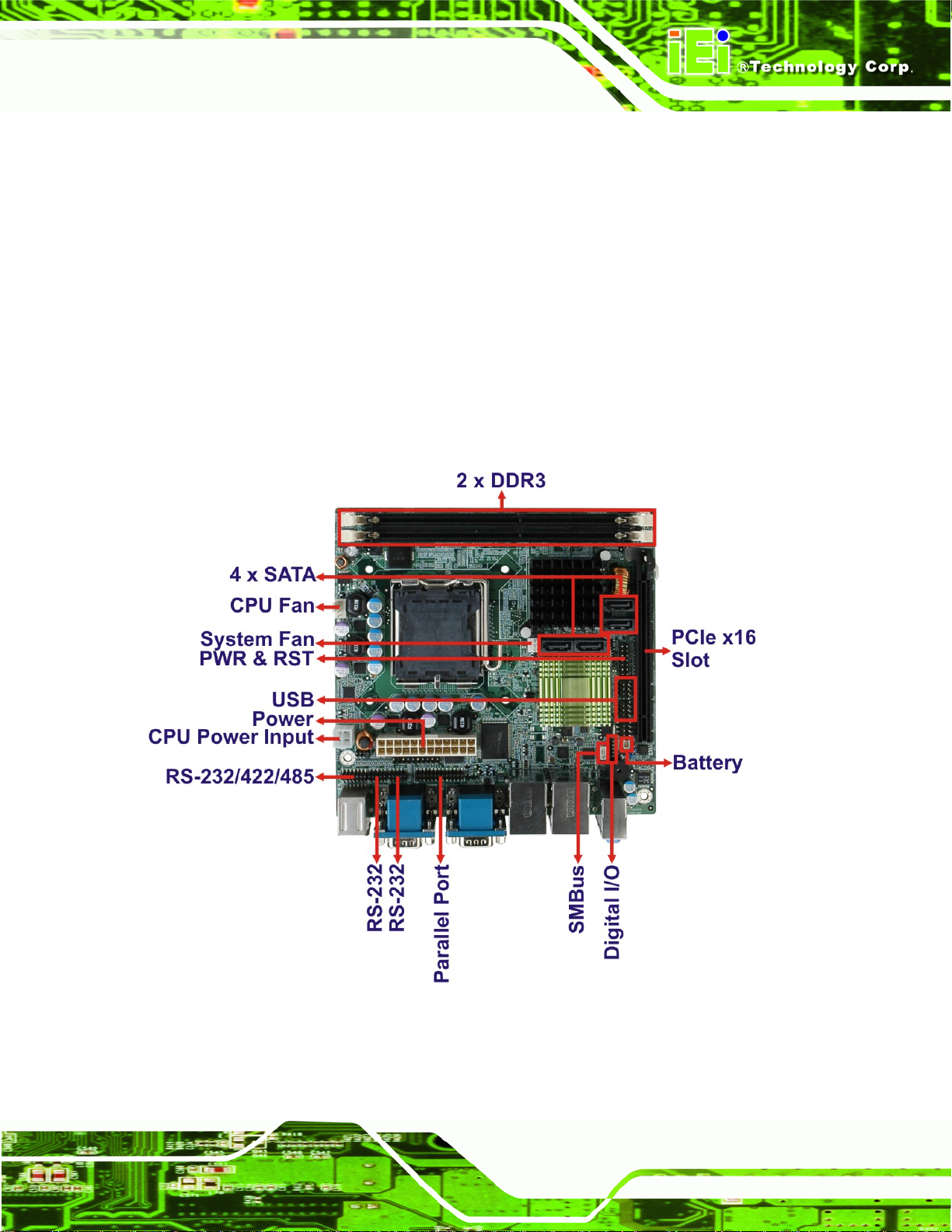
Figure 1-2: Connectors ..................................................................................................................3
Figure 1-3: Dimensions (mm)........................................................................................................4
Figure 1-4: Data Flow Diagram......................................................................................................5
Figure 3-1: Connectors and Jumpers.........................................................................................14
Figure 3-2: Battery Connector Location.....................................................................................16
Figure 3-3: CPU Fan Connector Location..................................................................................17
Figure 3-4: CPU Fan Connector Location..................................................................................18
Figure 3-5: CPU Power Input Connector Location....................................................................19
Figure 3-6: Digital I/O Connector Locations ..............................................................................19
Figure 3-7: Front Panel Connector Location .............................................................................20
Figure 3-8: Memory Card Slot Location .....................................................................................21
Figure 3-9: Parallel Port Connector Location............................................................................22
Figure 3-10: Power Connector Location ....................................................................................23
Figure 3-11: Serial Port Connector Location.............................................................................24
Figure 3-12: RS-232/422/485 Serial Port Connector Location..................................................25
Figure 3-13: SATA Drive Connector Location...........................................................................26
Figure 3-14: SMBus Connector Location...................................................................................27
Figure 3-15: SPI Flash Connector...............................................................................................27
Figure 3-16: USB Connector Pinout Locations.........................................................................28
Figure 3-17: VGA to LVDS Connector Location........................................................................29
Figure 3-18: External Peripheral Interface Connector..............................................................30
Figure 3-19: Audio Connector.....................................................................................................30
Figure 3-20: PS/2 Pinouts............................................................................................................31
Figure 3-21: Serial Port Pinouts..................................................................................................33
Figure 3-22: VGA Connector .......................................................................................................34
Figure 4-1: Intel LGA775 Socket .................................................................................................38
Figure 4-2: Remove Protective Cover.........................................................................................39
Figure 4-3: CPU Socket Load Plate.............................................................................................39
Figure 4-4: Insert the Socket LGA775 CPU................................................................................40
Page viii
Page 9

KINO-G410 Mini-ITX Motherboard
Figure 4-5: Cooling Kits...............................................................................................................41
Figure 4-6: Securing the Heat sink to the KINO-G410 ..............................................................42
Figure 4-7: DIMM Installation.......................................................................................................43
Figure 4-8: Clear BIOS Jumper Location ...................................................................................45
Figure 4-9: COM 6 Function Select Jumper Location...............................................................46
Figure 4-10: SATA Drive Cable Connection...............................................................................47
Figure 4-11: SATA Power Drive Connection..............................................................................48
Figure 4-12: Dual USB Cable Connection..................................................................................49
Figure 4-13: Audio Connector.....................................................................................................50
Figure 4-14: PS/2 Keyboard/Mouse Connector.........................................................................51
Figure 4-15: LAN Connection......................................................................................................52
Figure 4-16: Serial Device Connector.........................................................................................53
Figure 4-17: USB Connector........................................................................................................54
Figure 4-18: VGA Connector .......................................................................................................55
Figure C-1: IEI One Key Recovery Tool Menu........................................................................ 101
Figure C-2: Launching the Recovery Tool.............................................................................. 105
Figure C-3: Recovery Tool Setup Menu .................................................................................. 106
Figure C-4: Command Mode..................................................................................................... 106
Figure C-5: Partition Creation Commands.............................................................................. 107
Figure C-6: Launching the Recovery Tool.............................................................................. 109
Figure C-7: System Configuration for Windows .................................................................... 109
Figure C-8: Build-up Recovery Partition................................................................................. 110
Figure C-9: Press any key to continue.................................................................................... 110
Figure C-10: Press F3 to Boot into Recovery Mode............................................................... 111
Figure C-11: Recovery Tool Menu ........................................................................................... 111
Figure C-12: About Symantec Ghost Window........................................................................ 112
Figure C-13: Symantec Ghost Path ......................................................................................... 112
Figure C-14: Select a Local Source Drive ............................................................................... 113
Figure C-15: Select a Source Partition from Basic Drive ...................................................... 113
Figure C-16: File Name to Copy Image to ............................................................................... 114
Figure C-17: Compress Image.................................................................................................. 114
Figure C-18: Image Creation Confirmation............................................................................. 115
Figure C-19: Image Creation Process...................................................................................... 115
Figure C-20: Image Creation Complete................................................................................... 115
Figure C-21: Press Any Key to Continue................................................................................ 116
Page ix
Page 10

Figure C-22: Partitions for Linux.............................................................................................. 117
Figure C-23: System Configuration for Linux......................................................................... 118
Figure C-24: Access menu.lst in Linux (Text Mode).............................................................. 118
Figure C-25: Recovery Tool Menu ........................................................................................... 119
Figure C-26: Recovery Tool Main Menu.................................................................................. 120
Figure C-27: Restore Factory Default...................................................................................... 121
Figure C-28: Recovery Complete Window.............................................................................. 121
Figure C-29: Backup System.................................................................................................... 122
Figure C-30: System Backup Complete Window ................................................................... 122
Figure C-31: Restore Backup................................................................................................... 123
Figure C-32: Restore System Backup Complete Window..................................................... 123
Figure C-33: Symantec Ghost Window ................................................................................... 124
KINO-G410 Mini-ITX Motherboard
Page x
Page 11
KINO-G410 Mini-ITX Motherboard
List of Tables
Table 1-1: Technical Specifications..............................................................................................7
Table 2-1: Packing List.................................................................................................................10
Table 2-2: Optional Items.............................................................................................................12
Table 3–1: Internal Peripheral Connectors ................................................................................15
Table 3–2: External Peripheral Connectors...............................................................................16
Table 3-3: Battery Connector Pinouts........................................................................................17
Table 3-4: CPU Fan Connector Pinouts......................................................................................17
Table 3-5: CPU Fan Connector Pinouts......................................................................................18
Table 3-6: CPU Power Input Connector Pinouts.......................................................................19
Table 3-7: Digital I/O Connector Pinouts....................................................................................20
Table 3-8: Front Panel Connector Pinouts.................................................................................21
Table 3-9: Parallel Port Connector Pinouts ...............................................................................22
Table 3-10: Power Connector Pinouts........................................................................................23
Table 3-11: Serial Port Connector Pinouts ................................................................................24
Table 3-12: RS-232/422/485 Serial Port Connector Pinouts.....................................................25
Table 3-13: SMBus Connector Pinouts ......................................................................................27
Table 3-14: SPI Flash Connector.................................................................................................28
Table 3-15: USB Port Connector Pinouts...................................................................................28
Table 3-16: VGA to LVDS Connector Pinouts............................................................................29
Table 3-17: PS/2 Connector Pinouts...........................................................................................31
Table 3-18: LAN Pinouts ..............................................................................................................32
Table 3-19: Serial Port Pinouts....................................................................................................32
Table 3-20: USB Port Pinouts......................................................................................................33
Table 3-21: VGA Connector Pinouts...........................................................................................34
Table 4-1: Jumpers.......................................................................................................................44
Table 4-2: Clear BIOS Jumper Settings......................................................................................45
Table 4-3: COM 6 Function Select Jumper Settings.................................................................45
Table 5-1: BIOS Navigation Keys................................................................................................58
Page xi
Page 12
KINO-G410 Mini-ITX Motherboard
BIOS Menus
BIOS Menu 1: Main.......................................................................................................................59
BIOS Menu 2: Advanced..............................................................................................................61
BIOS Menu 3: CPU Configuration...............................................................................................61
BIOS Menu 4: IDE Configuration.................................................................................................62
BIOS Menu 5: IDE Master and IDE Slave Configuration...........................................................64
BIOS Menu 6: Super IO Configuration........................................................................................68
BIOS Menu 7: Hardware Health Configuration..........................................................................73
BIOS Menu 8: ACPI Configuration..............................................................................................75
BIOS Menu 9: ACPI Settings .......................................................................................................76
BIOS Menu 10: Remote Access Configuration..........................................................................77
BIOS Menu 11: USB Configuration.............................................................................................79
BIOS Menu 12: PCI/PnP Configuration.......................................................................................82
BIOS Menu 13: Boot.....................................................................................................................84
BIOS Menu 14: Boot Settings Configuration.............................................................................84
BIOS Menu 15: Security...............................................................................................................86
BIOS Menu 16: Chipset................................................................................................................88
BIOS Menu 17:North Bridge Chipset Configuration.................................................................88
BIOS Menu 18: South Bridge Chipset Configuration................................................................90
BIOS Menu 19: Exit.......................................................................................................................92
Page xii
Page 13

KINO-G410 Mini-ITX Motherboard
Chapter
1
1 Introduction
Page 1
Page 14
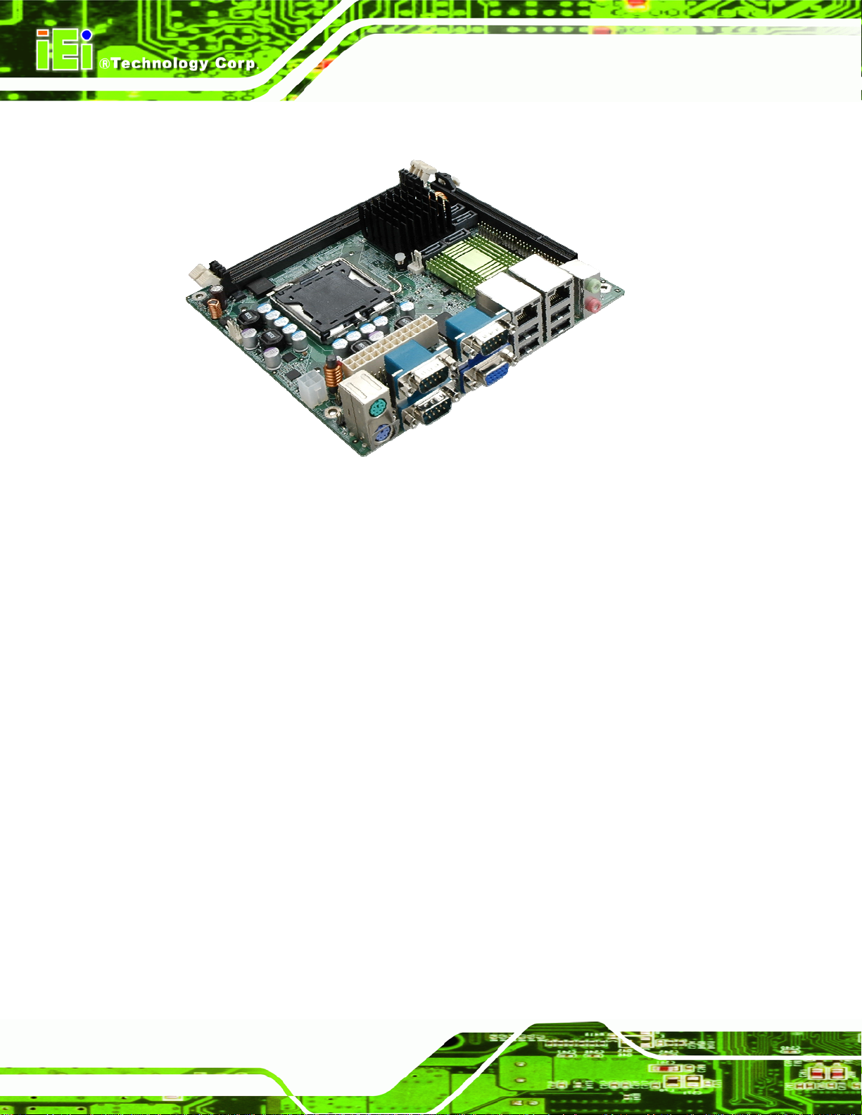
1.1 Introduction
Figure 1-1: KINO-G410
KINO-G410 Mini-ITX Motherboard
The KINO-G410 is a Mini-ITX motherboard with an 800/1066/1333 MHz front side bus.
The LGA775 socket accepts Intel® Core™2 Duo/Quad/Extreme processors and the card
supports two DDR3 DIMMs up to 2.0 GB each (4.0 GB total). The KINO-G410 includes
VGA output and an optional 24-bit LVDS output. One PCIe x16 expansion card may be
added. Other features include four SATA 3Gb/s, dual Gigabit LAN, digital I/O, five RS-232
serial ports, one RS-232/422/485 serial ports, one parallel port, audio jacks and eight USB
ports.
1.2 Benefits
Some of the KINO-G410 motherboard benefits include:
Powerful graphics
Staying connected with both wired LAN connections
Speedy running of multiple programs and applications
1.3 Features
Page 2
Some of the KINO-G410 motherboard features are listed below:
Mini-ITX form factor
Page 15
KINO-G410 Mini-ITX Motherboard
RoHS compliant
LGA775 CPU socket
Supports two DDR3 DIMMs
Two Gigabit Ethernet connectors
Four SATA connectors
Eight USB ports
Six serial ports
Support 24-bit LVDS by the optional VGA to LVDS converter module
1.4 Connectors
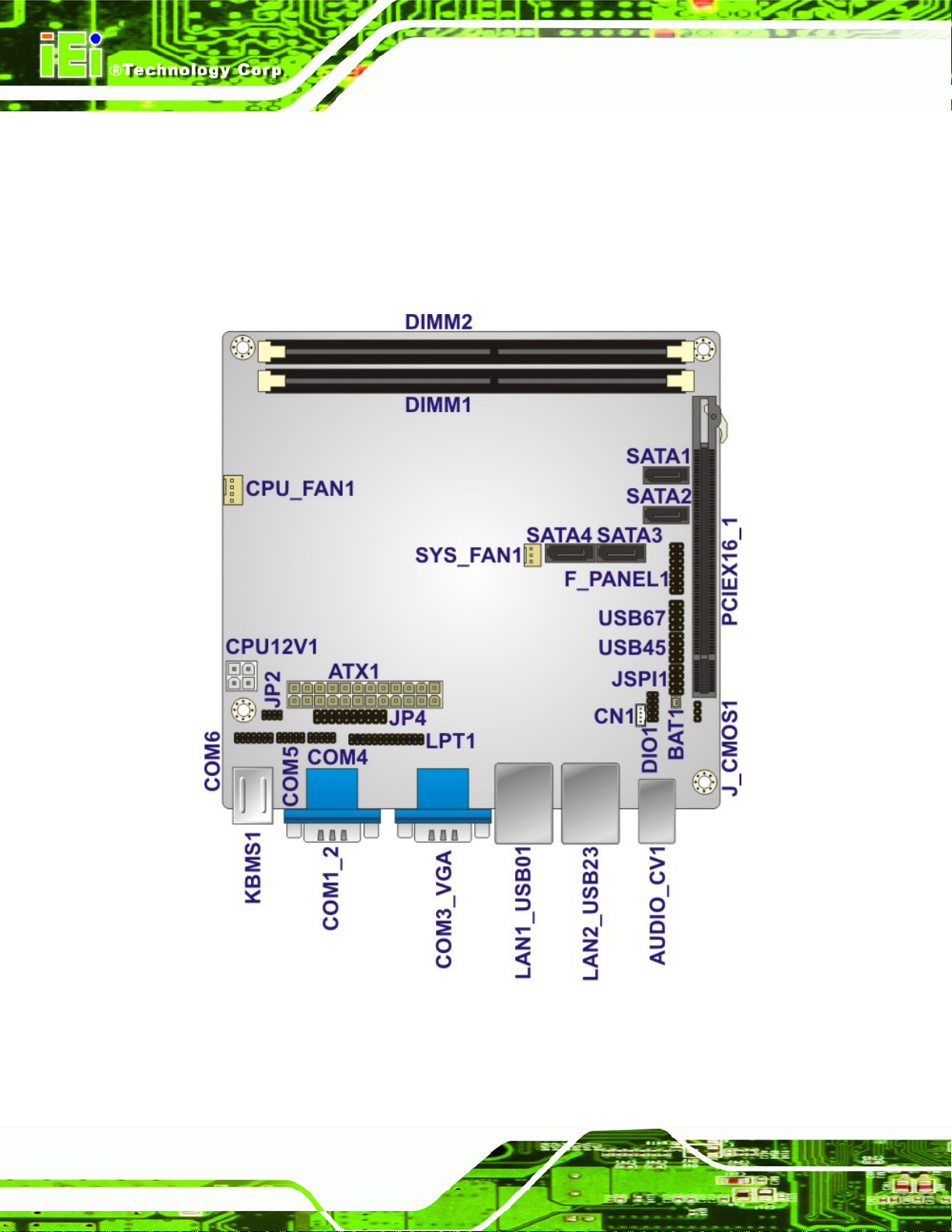
The connectors on the KINO-G410 are shown in the figure below.
Figure 1-2: Connectors
Page 3
Page 16
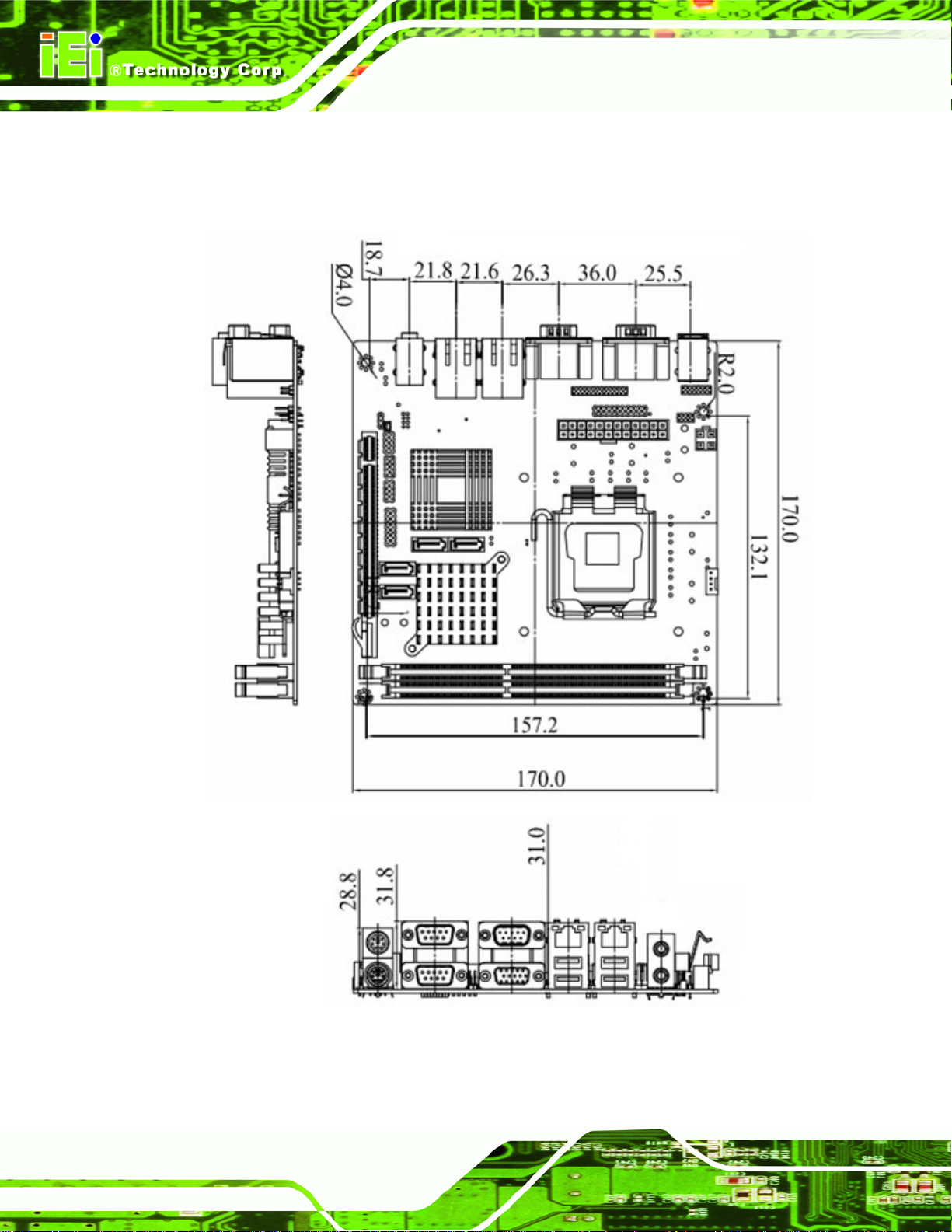
1.5 Dimensions
The main dimensions of the KINO-G410 are shown in the diagram below.
KINO-G410 Mini-ITX Motherboard
Page 4
Figure 1-3: Dimensions (mm)
Page 17
KINO-G410 Mini-ITX Motherboard
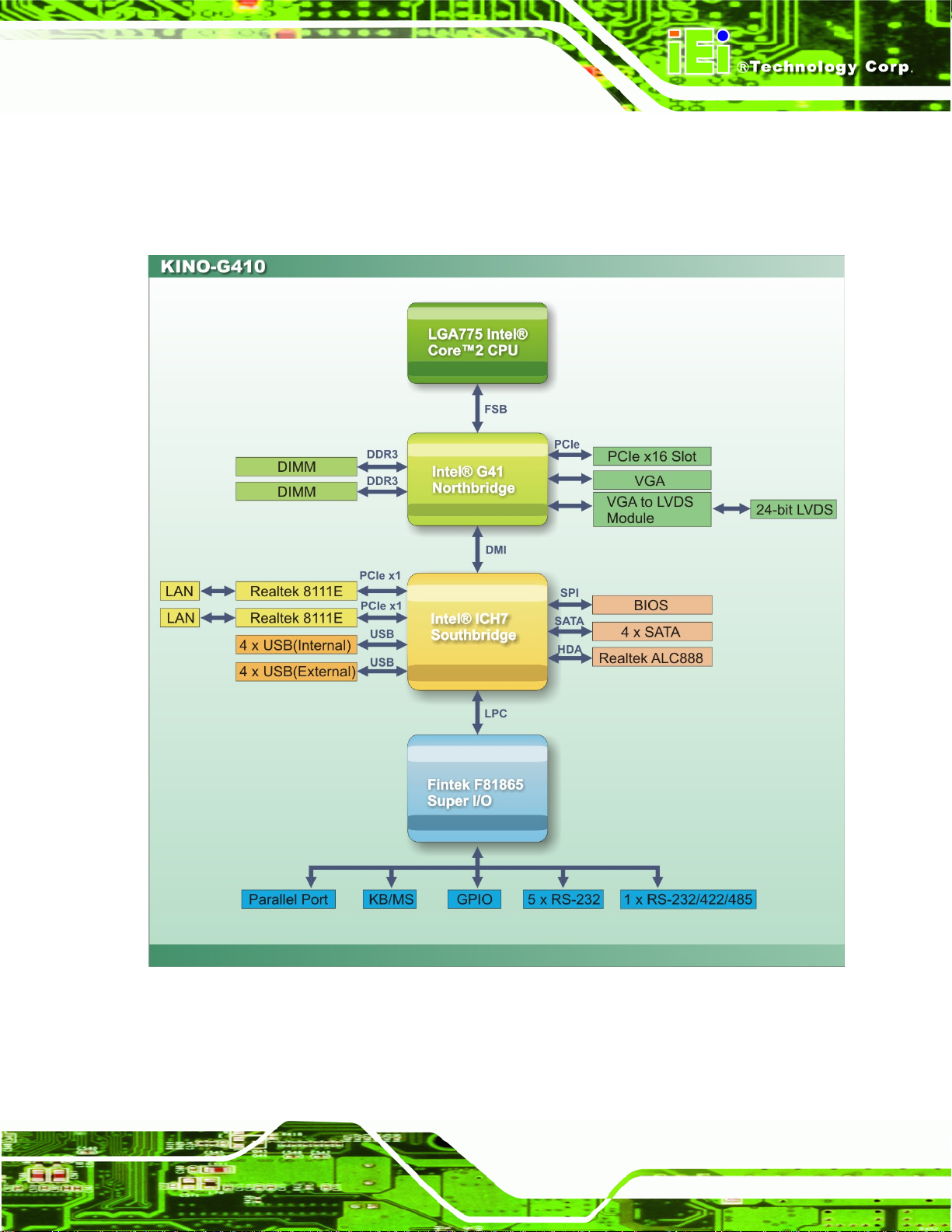
1.6 Data Flow
5Figure 1-4 shows the data flow between the system chipset, the CPU and other
components installed on the motherboard.
Figure 1-4: Data Flow Diagram
Page 5
Page 18
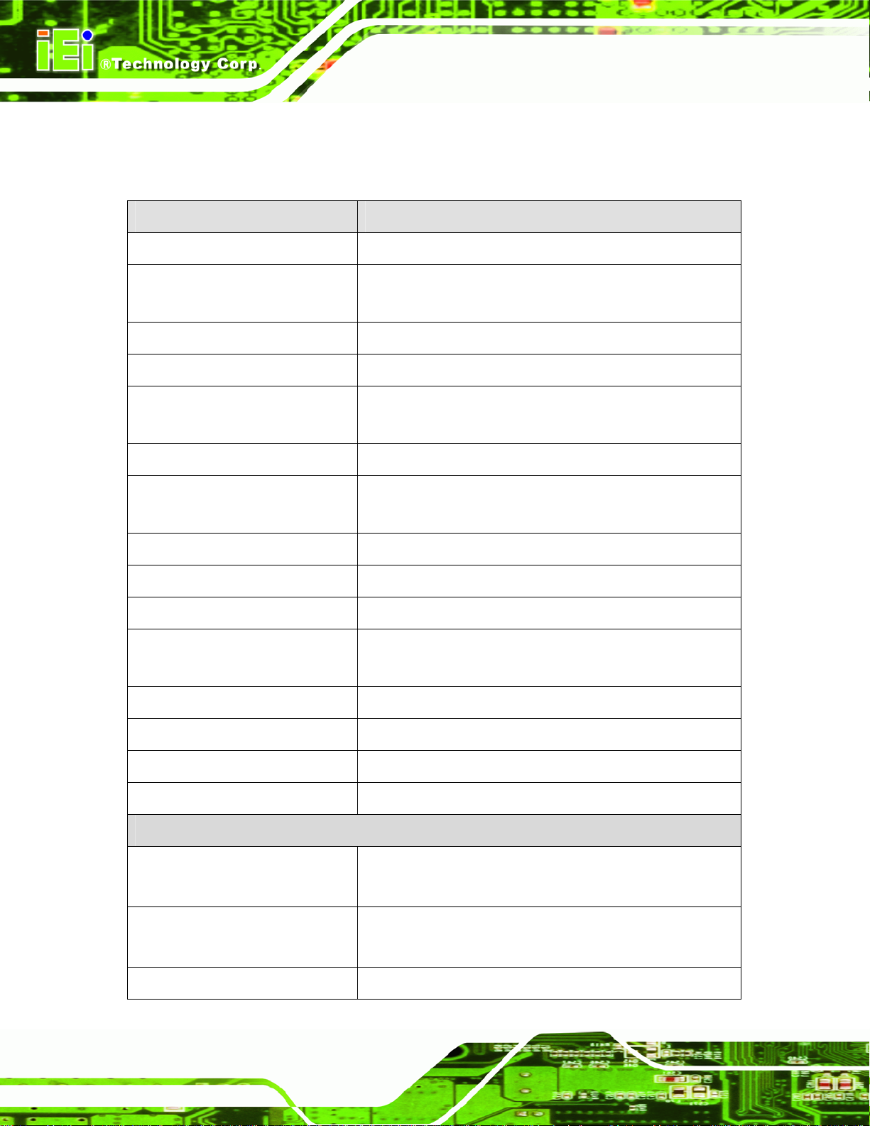
1.7 Technical Specifications
KINO-G410 technical specifications are shown below.
Specifications KINO-G410
KINO-G410 Mini-ITX Motherboard
Form Factor
CPU Supported
Front Side Bus (FSB)
Northbridge Chipset
Memory
Graphic Engine
Integrated Graphics
Southbridge Chipset
BIOS
Digital I/O
Ethernet Controllers
Mini-ITX
Socket LGA775 Intel® Core™2 Duo/Quad/Extreme or
Celeron® processor
800/1066/1333 MHz
Intel® G41
Two 240-pin 800/1066 MHz dual-channel DDR3 SDRAM
DIMMs (system max. 4 GB)
Intel® GMA4500
VGA integrated in Intel® G41
24-bit LVDS via VGA to LVDS converter module
Intel® ICH7
AMI BIOS
8-bit, 4-bit input/4-bit output
Two Realtek RTL8111E PCIe GbE controllers with ASF2.0
Super I/O Controller
Watchdog Timer
Audio
Expansion
I/O Interface
Audio Jack
Fan connector
Keyboard/Mouse
Page 6
support
Fintek F81865
Software programmable supports 1~2 55 sec. system reset
Realtek ALC888 HD Audio codec
One PCIe x16 socket
One line-out
One mic-in
One 4-pin wafer for CPU fan
One 3-pin wafer for system fan
Two external PS/2 connectors
Page 19

KINO-G410 Mini-ITX Motherboard
Serial Ports
USB 2.0/1.1 ports
Parallel Port
Serial ATA
Environmental and Power Specifications
Power Supply
Power Consumption
Five RS-232 COM connectors
One RS-232/422/485 COM connector
Four internal via pin header
Four external USB ports
One parallel port via 26-pin header
Four independent SATA channels with 3.0 Gb/s data
transfer rates
ATX supported
5 V @ 6.41 A
Vcore_12 V @ 2.52 A
3.3 V @ 0.27 A
(2.8 GHz Intel® Core2 Duo E7400 with two 1 GB
1066 MHz DDR3 DIMMs)
Operating temperature
Humidity
Physical Specifications
Dimensions
Weight (Gross/Net)
Table 1-1: Technical Specifications
-10ºC ~ 60ºC, requires cooler and silicone heat sink paste
5% ~ 95% (non-condensing)
170 mm x 170 mm
1100 g / 700 g
Page 7
Page 20
KINO-G410 Mini-ITX Motherboard
Chapter
2
2 Packing List
Page 8
Page 21
KINO-G410 Mini-ITX Motherboard
2.1 Anti-static Precautions
WARNING!
Static electricity can destroy certain electronics. Make sure to follow the
ESD precautions to prevent damage to the product, and injury to the
user.
Make sure to adhere to the following guidelines:
Wear an anti-static wristband: Wearing an anti-static wristband can prevent
electrostatic discharge.
Self-grounding: Touch a grounded conductor every few minutes to discharge
any excess static buildup.
Use an anti-static pad: When configuring any circuit board, place it on an
anti-static mat.
Only handle the edges of the PCB: Don't touch the surface of the
motherboard. Hold the motherboard by the edges when handling.
2.2 Unpacking Precautions
When the KINO-G410 is unpacked, please do the following:
Follow the antistatic guidelines above.
Make sure the packing box is facing upwards whe n opening.
Make sure all the packing list items are present.
Page 9
Page 22
2.3 Packing List
NOTE:
If any of the components listed in the checklist below are missing, do
not proceed with the installation. Contact the IEI reseller or vendor the
KINO-G410 was purchased from or contact an IEI sales representative
KINO-G410 Mini-ITX Motherboard
directly by sending an email to
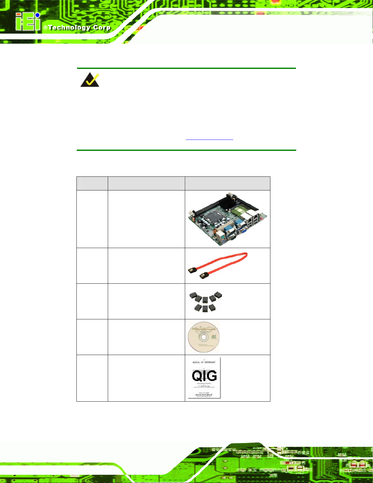
The KINO-G410 is shipped with the following components:
Quantity Item and Part Number Image
1 KINO-G410 SBC
2 SATA cable
(P/N: 32000-062800-RS)
1 Mini jumper pack (2.0mm)
(P/N:33100-000033-RS)
32sales@iei.com.tw.
Page 10
1 Utility CD
1 Quick Installation Guide
Table 2-1: Packing List
Page 23
KINO-G410 Mini-ITX Motherboard
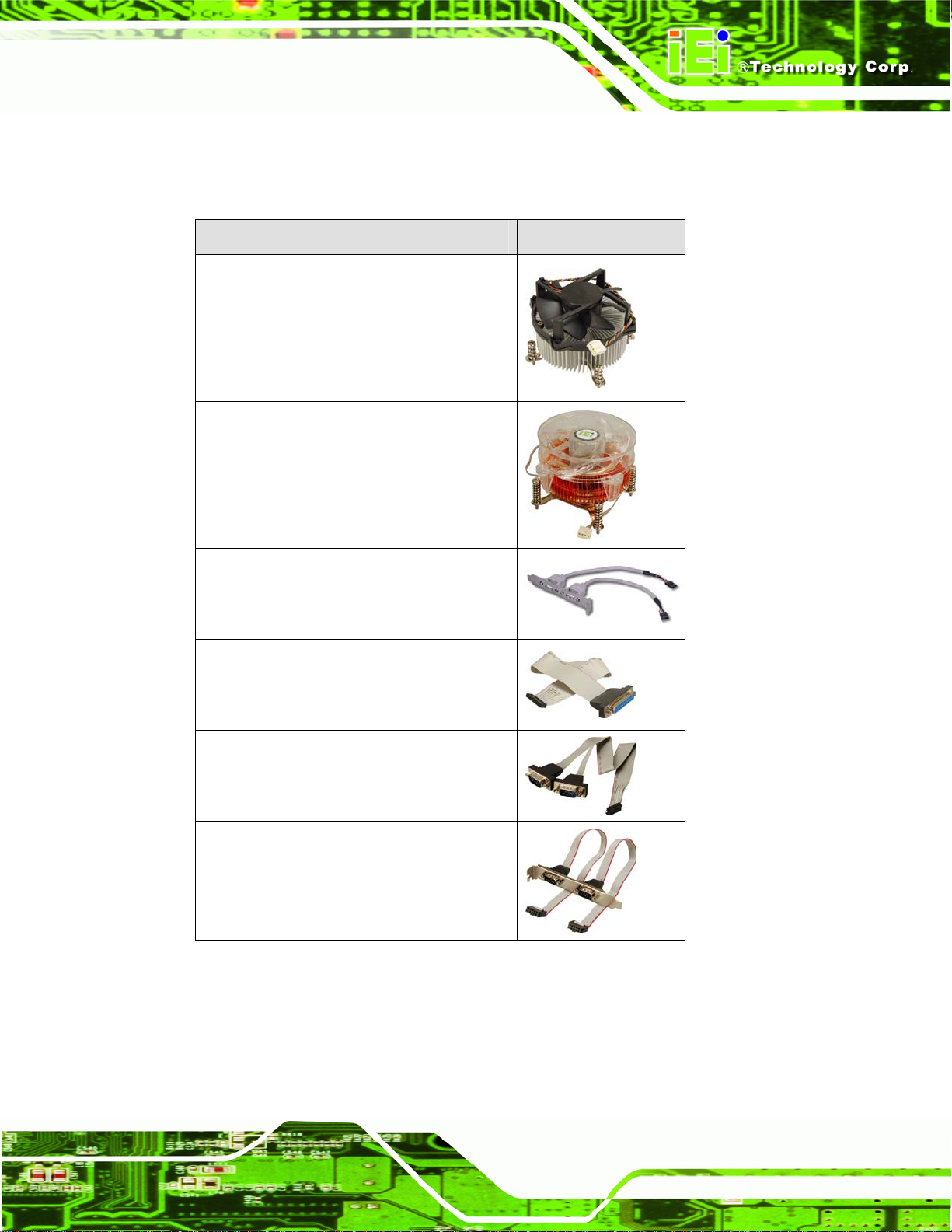
2.4 Optional Items
The following are optional components which may be separately purchased:
Item and Part Number Image
CPU cooler kit
(P/N: CF-520-RS-R1 1 )
CPU cooler kit
(P/N: CF-775A-RS)
USB cable
(P/N: CB-USB02-RS
LPT cable (w/o bracket)
(P/N: 32200-015100-RS)
RS-232/422/485 cable
(P/N: 32205-000300-100-RS)
Dual RS-232 cable
(P/N: 19800-000051-RS)
Page 11
Page 24
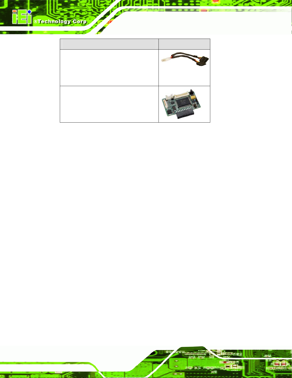
Item and Part Number Image
SATA power cable
(P/N: 32100-088600-RS
32102-000100-100-RS
32102-000100-200-RS)
VGA to LVDS (24-bit) converter module
(P/N: VGA-LVDS-R10)
Table 2-2: Optional Items
KINO-G410 Mini-ITX Motherboard
Page 12
Page 25
KINO-G410 Mini-ITX Motherboard
Chapter
3
3 Connectors
Page 13
Page 26
3.1 Peripheral Interface Connectors
This chapter details all the jumpers and connectors.
3.1.1 Layout
The figure below shows all the connectors and jumpers.
KINO-G410 Mini-ITX Motherboard
Page 14
Figure 3-1: Connectors and Jumpers
Page 27
KINO-G410 Mini-ITX Motherboard
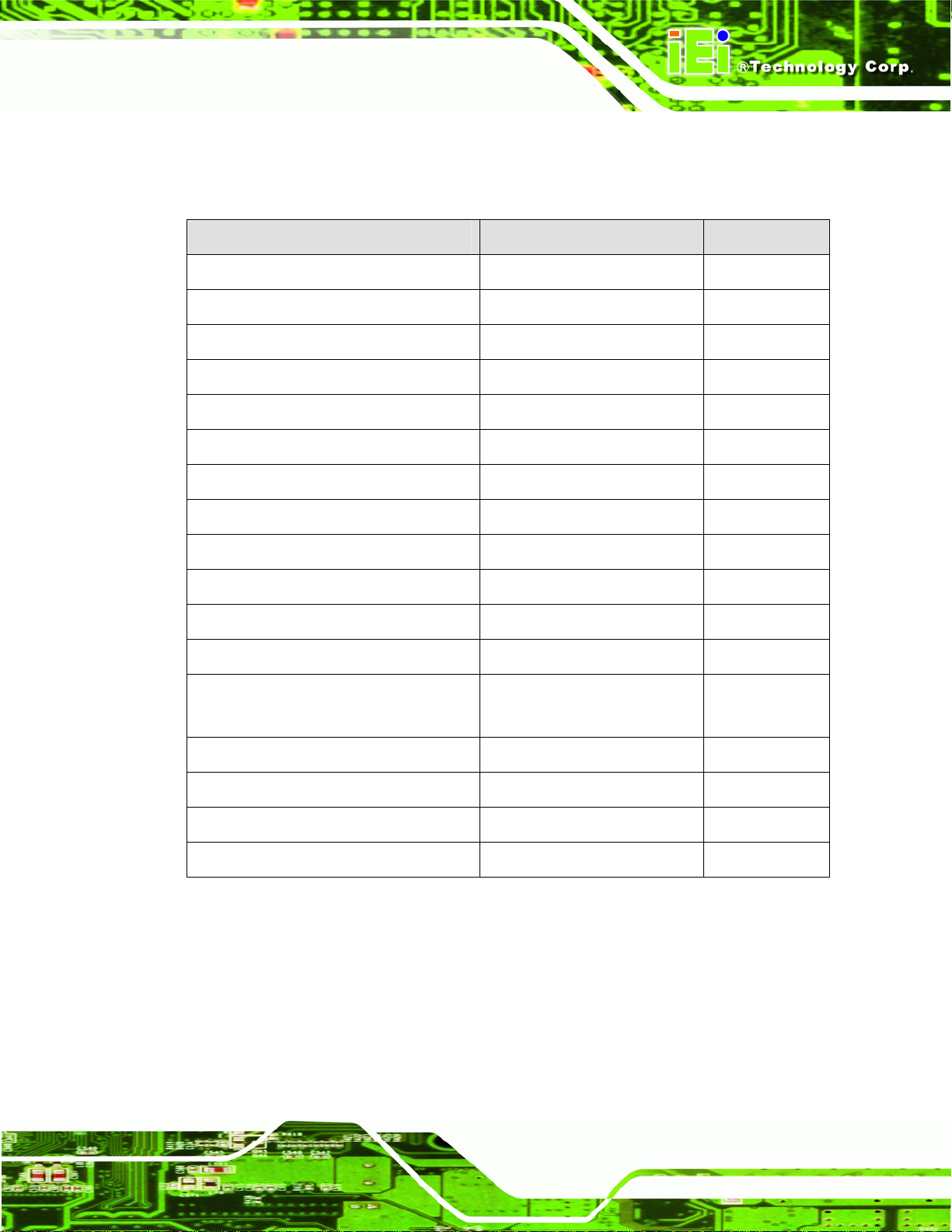
3.1.2 Peripheral Interface Connectors
The table below lists all the connectors on the board.
Connector Type Label
Battery connector 2-pin wafer BAT1
Fan connector (CPU) 4-pin wafer CPU_FAN1
Fan connector (system) 3-pin wafer SYS_FAN1
CPU Power Input Connector 4-pin connector CPU12V1
Digital I/O connector 10-pin header DIO1
Front panel connector 14-pin header F_PANEL1
Memory slot 204-pin DDR3 DIMM slot DIMM1, DIMM2
Parallel port connector 26-pin header LPT1
PCIe x16 slot PCIe x16 slot PCIEX16_1
Power connector 24-pin connector ATX1
RS-232 serial port connector 10-pin header COM4, COM5
RS-232/422/485 serial port connector 14-pin header COM6
SATA drive connectors 7-pin SATA drive connectors SATA1, SATA2,
SATA3, SATA4
SMBus connector 4-pin wafer CN1
SPI Flash connector 8-pin h eader JSPI1
USB connectors 8-pin header USB45, USB67
VGA to LVDS connector 20-pin header JP4
Table 3–1: Internal Peripheral Connectors
3.1.3 External Interface Panel Connectors
The table below lists the connectors on the external I/O panel.
Page 15
Page 28
Connector Type Label
Audio connector Audio jack AUDIO_CV1
Keyboard/Mouse connector PS/2 KBMS1
LAN connector RJ-45 LAN1, LAN2
Serial port connector DB-9 COM1, COM2,
USB connector USB port USB01, USB23
VGA connector 15-pin Female VGA1
Table 3–2: External Peripheral Connectors
3.2 Internal Peripheral Connectors
The section describes all of the connectors on the KINO-G410.
KINO-G410 Mini-ITX Motherboard
COM3
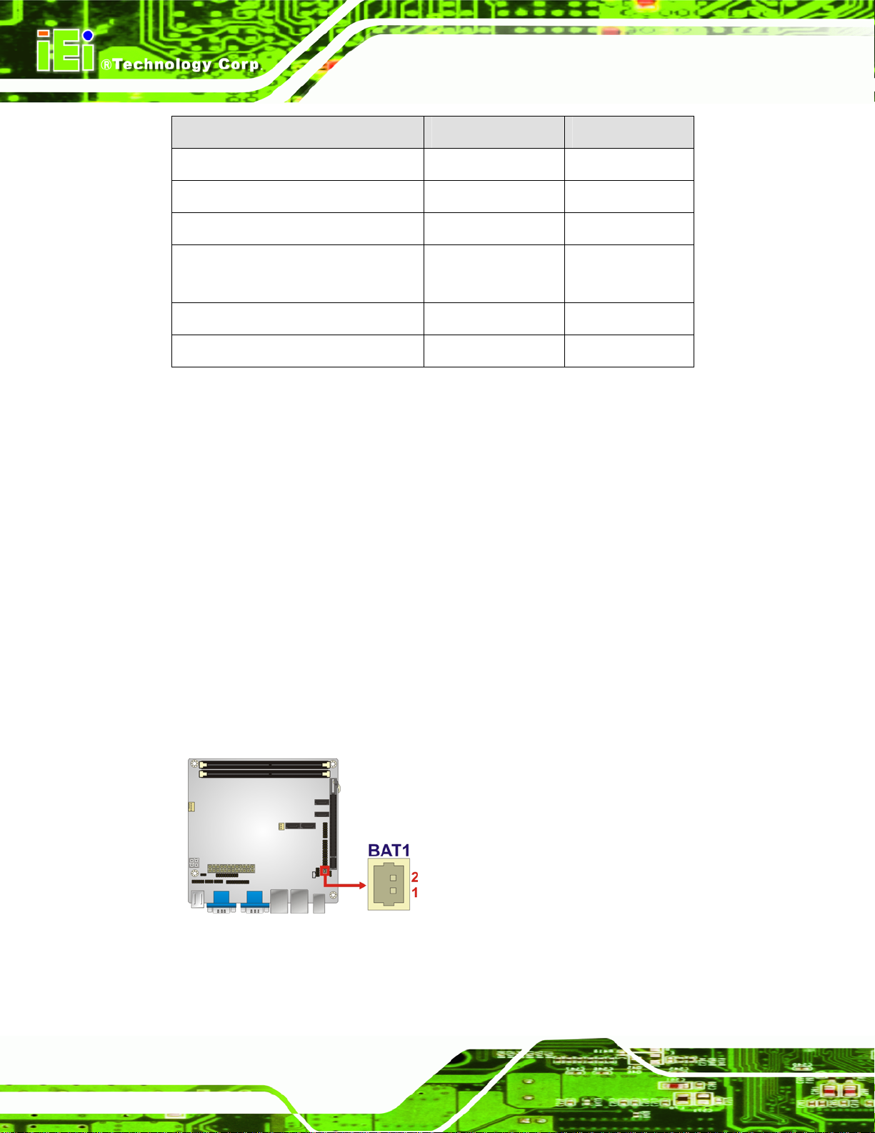
3.2.1 Battery Connector
CN Label: BAT1
CN Type:
CN Location:
CN Pinouts:
This is connected to the system battery. The battery provides power to the system clock to
retain the time when power is turned off.
Figure 3-2: Battery Connector Location
2-pin wafer
Figure 3-2
See
Table 3-3
See
Page 16
Page 29
KINO-G410 Mini-ITX Motherboard
Pin Description
1 Battery+ (+3V)
2 Ground
Table 3-3: Battery Connector Pinouts
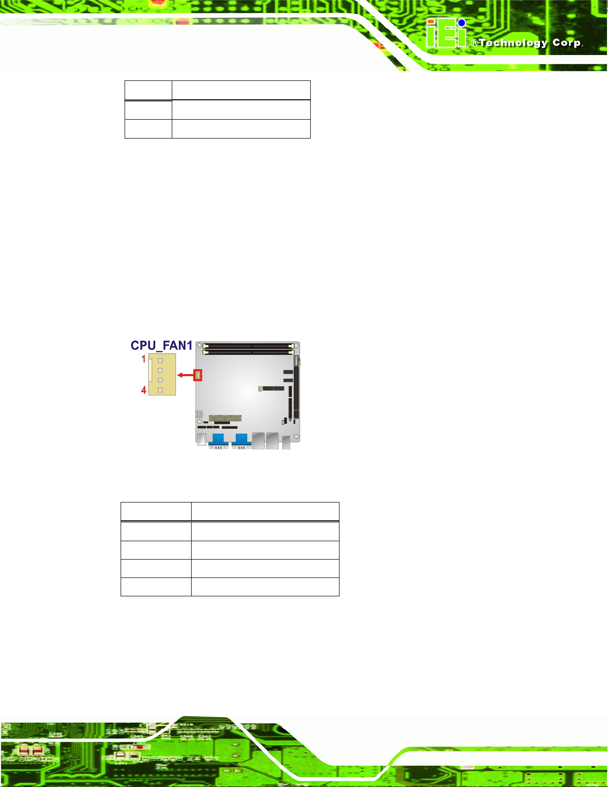
3.2.2 CPU Fan Connector
CN Label: CPU_FAN1
CN Type:
CN Location:
CN Pinouts:
4-pin wafer
Figure 3-3
See
Table 3-4
See
The fan connector attaches to a CPU cooling fan.
Figure 3-3: CPU Fan Connector Location
Pin Description
1 GND
2 +12 V
3 Fan In
4 Fan Control
Table 3-4: CPU Fan Connector Pinouts
Page 17
Page 30
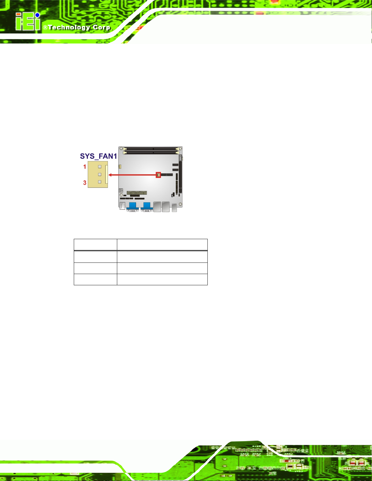
3.2.3 System Fan Connector
CN Label: SYS_FAN1
KINO-G410 Mini-ITX Motherboard
CN Type:
CN Location:
CN Pinouts:
The fan connector attaches to a system cooling fan.
Figure 3-4: CPU Fan Connector Location
3-pin wafer
Figure 3-4
See
Table 3-5
See
Pin Description
1 Fan In
2 VCC_FAN
3 GND
Table 3-5: CPU Fan Connector Pinouts
3.2.4 CPU Power Input Connector
CN Label: CPU12V1
CN Type:
CN Location:
CN Pinouts:
The CPU power input connector provides power to the CPU.
4-pin connector
Figure 3-5
See
Table 3-6
See
Page 18
Page 31

KINO-G410 Mini-ITX Motherboard
Figure 3-5: CPU Power Input Connector Location
Pin Description
1 GND
2 GND
3 +12 V
4 +12 V
Table 3-6: CPU Power Input Connector Pinouts
3.2.5 Digital I/O Connector
CN Label: DIO1
CN Type:
CN Location:
CN Pinouts:
The digital I/O connector provides programmable input and output for external devices.
The digital I/O provides 4-bit output and 4-bit input.
Figure 3-6: Digital I/O Connector Locations
10-pin header
Figure 3-6
See
Table 3-7
See
Page 19
Page 32

Pin Description Pin Description
1 GND 2 VCC5S
3 Output 3 4 Output 2
5 Output 1 6 Output 0
7 Input 3 8 Input 2
9 Input 1 10 Input 0
Table 3-7: Digital I/O Connector Pinouts
3.2.6 Front Panel Connector
CN Label: F_PANEL1
KINO-G410 Mini-ITX Motherboard
CN Type:
CN Location:
CN Pinouts:
The front panel connector connects to the indicator LEDs and buttons on the computer's
front panel.
Figure 3-7: Front Panel Connector Location
14-pin header
Figure 3-7
See
Table 3-8
See
Page 20
Page 33

KINO-G410 Mini-ITX Motherboard
FUNCTION PIN DESCRIPTION FUNCTION PIN DESCRIPTION
Power LED
Power
Button
1 LED+ 2 BEEP_PWR
3 NC 4 NC
5 LED- 6 NC
7 BUTTON1
9 BUTTON2
11 HDD LED+ 12 RESET HDD LED
13 HDD LED-
Table 3-8: Front Panel Connector Pinouts
3.2.7 Memory Slot
CN Label: DIMM1, DIMM2
CN Type:
CN Location:
The DIMM slots are for DIMM memory modules.
DIMM slot
Figure 3-8
See
Buzzer
8 PC_BEEP
-- 10 NC
Reset
14 GND
Figure 3-8: Memory Card Slot Location
3.2.8 Parallel Port Connector
CN Label: LPT1
CN Type:
26-pin header
Page 21
Page 34

See
CN Location:
CN Pinouts:
Figure 3-9
Table 3-9
See
KINO-G410 Mini-ITX Motherboard
The parallel port connector connects to a parallel port connector interface or some other
parallel port device such as a printer.
Figure 3-9: Parallel Port Connector Location
Pin Description Pin Description
1 -STB 2 -AFD
3 PTD0 4 -ERR
5 PTD1 6 -INITR
7 PTD2 8 -SLIN
9 PTD3 10 GND
11 PTD4 12 GND
13 PTD5 14 GND
15 PTD6 16 GND
17 PTD7 18 GND
19 -ACK 20 GND
21 BUSY 22 GND
23 PE 24 GND
Page 22
25 SLCT 26 NC
Table 3-9: Parallel Port Connector Pinouts
Page 35

KINO-G410 Mini-ITX Motherboard
3.2.9 Power Connector
CN Label: ATX1
CN Type:
CN Location:
CN Pinouts:
24-pin connector
Figure 3-10
See
Table 3-10
See
The power connector connects to an ATX power supply.
Figure 3-10: Power Connector Location
Pin Description Pin Description
1 3.3V 13 3.3V
2 3.3V 14 -12V
3 GND 15 GND
4 5V 16 PS_ON5 GND 17 GND
6 5V 18 GND
7 GND 19 GND
8 ATXPWROK 20 NC
9 5VSB 21 5V
10 12V 22 5V
11 12V 23 5V
12 3.3V 24 GND
Table 3-10: Power Connector Pinouts
Page 23
Page 36

3.2.10 RS-232 Serial Port Connector
CN Label: COM4, COM5
KINO-G410 Mini-ITX Motherboard
CN Type:
CN Location:
CN Pinouts:
10-pin header
Figure 3-11
See
Table 3-11
See
This connector provides RS-232 communications.
Figure 3-11: Serial Port Connector Location
Page 24
Pin Description
1 Data Carrier Direct (DCD)
2 Receive Data (RXD)
3 Transmit Data (TXD)
4 Data Terminal Ready (DTR)
5 Ground (GND)
6 Data Set Ready (DSR)
7 Request To Send (RTS)
8 Clear To Send (CTS)
9 Ring Indicator (RI)
10 GND
Table 3-11: Serial Port Connector Pinouts
Page 37

KINO-G410 Mini-ITX Motherboard
3.2.11 RS-232/422/485 Serial Port Connector
CN Label: COM6
CN Type:
CN Location:
CN Pinouts:
14-pin header
Figure 3-12
See
Table 3-12
See
This connector provides RS-232, RS-422 or RS-485 communi cations.
Figure 3-12: RS-232/422/485 Serial Port Connector Location
Pin Description Pin Description
1 DCD 2 DSR
3 RXD 4 RTS
5 TXD 6 CTS
7 DTR 8 RI
9 GND 10 GND
11 RS422 TX2/485 12 RS422 TX2-/485
13 RS422 RX2 14 RS422 RX2-
Table 3-12: RS-232/422/485 Serial Port Connector Pinouts
Page 25
Page 38

3.2.12 SATA Drive Connectors
CN Label: SATA1, SATA2, SATA3, SATA4
KINO-G410 Mini-ITX Motherboard
CN Type:
CN Location:
The SATA drive connectors can be connected to SATA 3Gb/s drives.
Figure 3-13: SATA Drive Connector Location
7-pin SATA drive connectors
Figure 3-13
See
3.2.13 SMBus Connector
CN Label: CN1
CN Type:
CN Location:
CN Pinouts:
The SMBus (System Management Bus) connector provides low-speed system
management communications.
4-pin wafer
Figure 3-14
See
Table 3-13
See
Page 26
Page 39

KINO-G410 Mini-ITX Motherboard
Figure 3-14: SMBus Connector Location
Pin Description
1 GND
2 SDAT
3 SCLK
4 +5V
Table 3-13: SMBus Connector Pinouts
3.2.14 SPI Flash Connector
CN Label: JSPI1
CN Type:
CN Location:
CN Pinouts:
The 8-pin SPI Flash connector is used to flash the BIOS.
8-pin header
Figure 3-15
See
Table 3-14
See
Figure 3-15: SPI Flash Connector
Page 27
Page 40

Pin Description Pin Description
1 +3.3V 2 GND
3 CS# 4 CLOCK
5 SO 6 SI
7 NC 8 NC
Table 3-14: SPI Flash Connector
3.2.15 USB Connectors
CN Label: USB45, USB67
KINO-G410 Mini-ITX Motherboard
CN Type:
CN Location:
CN Pinouts:
8-pin header
Figure 3-16
See
Table 3-15
See
The USB connectors connect to USB devices. Each pin header provides two USB ports.
Figure 3-16: USB Connector Pinout Locations
Pin Description Pin Description
Page 28
1 +5V 2 GND
3 DATA1- 4 DATA2+
5 DATA1+ 6 DATA27 GND 8 +5V
Table 3-15: USB Port Connector Pinouts
Page 41

KINO-G410 Mini-ITX Motherboard
3.2.16 VGA to LVDS Connector
CN Label: JP4
CN Type:
CN Location:
CN Pinouts:
20-pin header
Figure 3-17
See
Table 3-16
See
This connector connects to the optional VGA to LVDS converter module and provides the
24-bit LVDS interface.
Figure 3-17: VGA to LVDS Connector Location
Pin Description Pin Description
1 GND 2 +5V
3 H-SYNCBUF-OUT_R 4 NC
5 V-SYNCBUF-OUT_R 6 +5V
7 GND 8 GND
9 CH1BUF-OUT_RED 10 +3.3V
11 CH1BUF-OUT_GREEN 12 +3.3V
13 CH1BUF-OUT_BLUE 14 +3.3V
15 GND 16 GND
17 5VDDCDA 18 +12V
19 5VDDCCLK 20 +12V
Table 3-16: VGA to LVDS Connector Pinouts
Page 29
Page 42

KINO-G410 Mini-ITX Motherboard
3.3 External Peripheral Interface Connector Panel
The figure below shows the external peripheral interface connector (EPIC) panel. The
EPIC panel consists of the following:
Figure 3-18: External Peripheral Interface Connector
3.3.1 Audio Connector
CN Label: AUDIO_CV1
CN Type:
CN Location:
The audio jacks connect to external audio devices.
Line Out port (Lime): Connects to a head phone or a speaker. With
multi-channel configurations, this port can also connect to front speakers.
Microphone (Pink): Connects a microphone.
Audio jacks
Figure 3-18
See
Page 30
Figure 3-19: Audio Connector
Page 43

KINO-G410 Mini-ITX Motherboard
3.3.2 Keyboard/Mouse Connector
CN Label: KBMS1
CN Type:
CN Location:
CN Pinouts:
PS/2
Figure 3-18
See
Figure 3-20, Table 3-17
See
The PS/2 ports are for connecting a PS/2 mouse and a PS/2 keyboard.
Figure 3-20: PS/2 Pinouts
Pin Description Pin Description
1 L_KDAT 7 L_MDAT
2 NC 8 NC
3 GND 9 GND
4 5 V 10 5 V
5 L_KCLK 11 L_MCLK
6 NC 12 NC
Table 3-17: PS/2 Connector Pinouts
Page 31
Page 44
3.3.3 LAN Connector
CN Label: LAN1, LAN2
KINO-G410 Mini-ITX Motherboard
CN Type:
CN Location:
CN Pinouts:
RJ-45
Figure 3-18
See
Table 3-18
See
The LAN connector connects to a local network.
Pin Description Pin Description
1 MDIA3- 5 MDIA1+
2 MDIA3+ 6 MDIA2+3 MDIA2- 7 MDIA04 MDIA1- 8 MDIA0+
Table 3-18: LAN Pinouts
3.3.4 Serial Port Connectors (COM1, COM2 and COM3)
CN Label: COM1, COM2, COM3
CN Type:
CN Location:
CN Pinouts:
DB-9 connectors
Figure 3-18
See
Table 3-19 and Figure 3-21
See
The serial port connects to a RS-232 serial communications device.
Pin Description Pin Description
1 DCD 6 DSR
2 RX 7 RTS
3 TX 8 CTS
4 DTR 9 RI
5 GND
Table 3-19: Serial Port Pinouts
Page 32
Page 45

KINO-G410 Mini-ITX Motherboard
Figure 3-21: Serial Port Pinouts
3.3.5 USB Connector
CN Label: USB01, USB23
CN Type:
CN Location:
CN Pinouts:
The USB connector can be connected to a USB device.
Pin Description Pin Description
1 +5 V 2 +5 V
3 DATA- 4 DATA5 DATA+ 6 DATA+
7 GND 8 GND
Table 3-20: USB Port Pinouts
USB port
Figure 3-18
See
Table 3-20
See
3.3.6 VGA Connector
CN Label: VGA1
CN Type:
CN Location:
CN Pinouts:
The VGA connector connects to a monitor that accepts a standard VGA input.
15-pin Female
Figure 3-18
See
Figure 3-22 and Table 3-21
See
Page 33
Page 46

KINO-G410 Mini-ITX Motherboard
Figure 3-22: VGA Connector
Pin Description Pin Description
1 RED 2 GREEN
3 BLUE 4 NC
5 GND 6 GND
7 GND 8 GND
9 VCC / NC 10 GND
11 NC 12 DDC DAT
13 HSYNC 14 VSYNC
15 DDCCLK
Table 3-21: VGA Connector Pinouts
Page 34
Page 47

KINO-G410 Mini-ITX Motherboard
Chapter
4
4 Installation
Page 35
Page 48

4.1 Anti-static Precautions
WARNING:
Failure to take ESD precautions during the installation of the
KINO-G410 may result in permanent damage to the KINO-G410 and
severe injury to the user.
Electrostatic discharge (ESD) can cause serious damage to electronic components,
including the KINO-G410. Dry climates are especially susceptible to ESD. It is therefore
critical that whenever the KINO-G410 or any other electrical component is handled, the
following anti-static precautions are strictly adhered to.
Wear an anti-static wristband: Wearing a simple an ti-static wristband can
KINO-G410 Mini-ITX Motherboard
help to prevent ESD from damaging the board.
Self-grounding: Before handling the board, touch any grounded conducting
material. During the time the board is handled, frequently touch any
conducting materials that are connected to the ground.
Use an anti-static pad: When configuring the KINO-G410, place it on an
antic-static pad. This reduces the possibility of ESD damaging the
KINO-G410.
Only handle the edges of the PCB: When handling the PCB, hold the PCB
by the edges.
4.2 Installation Considerations
NOTE:
The following installation notices and installation considerations should
be read and understood before installation. All installation notices must
Page 36
be strictly adhered to. Failing to adhere to these precautions may lead
to severe damage and injury to the person performing the installation.
Page 49
KINO-G410 Mini-ITX Motherboard
WARNING:
The installation instructions described in this manual should be
carefully followed in order to prevent damage to the components and
injury to the user.
Before and during the installation please DO the following:
Read the user manual:
o The user manual provides a complete description of the KINO-G410
installation instructions and configuration options.
Wear an electrostatic discharge cuff (ESD):
o Electronic components are easily damaged by ESD. Wearing an ESD cuff
removes ESD from the body and helps prevent ESD damage.
Place the KINO-G410 on an antistatic pad:
o When installing or configuring the motherboard, place it on an antistatic
pad. This helps to prevent potential ESD damage.
Turn all power to the KINO-G410 off:
o When working with the KINO-G410, make sure that it is disconnected
from all power supplies and that no electricity is being fed into the system.
Before and during the installation of the KINO-G410 DO NOT:
Remove any of the stickers on the PCB board. These stickers are required for
warranty validation.
Use the product before verifying all the cables and power connectors are
properly connected.
Allow screws to come in contact with the PCB circuit, connector pins, or its
components.
Page 37
Page 50

4.3 Basic Installation
This section outlines the parts that must be installed for the system to function correctly.
4.3.1 CPU Installation
NOTE:
To enable Hyper-Threading, the CPU and chipset must both support it.
WARNING:
CPUs are expensive and sensitive components. When installing the
KINO-G410 Mini-ITX Motherboard
CPU please be careful not to damage it in anyway. Make sure the CPU
is installed properly and ensure the correct cooling kit is properly
installed.
The LGA775 socket is shown in Figure 4-1.
Figure 4-1: Intel LGA775 Socket
To install the CPU, follow the steps below.
Page 38
Page 51

KINO-G410 Mini-ITX Motherboard
WARNING:
DO NOT touch the pins at the bottom of the CPU. When handling the
CPU, only hold it on the sides.
Step 1: Remove the protective cover. The black protective cover can be removed by
pulling up on the tab labeled "Remove". See
Figure 4-2: Remove Protective Cover
Step 2: Open the socket. Disengage the load lever by pressing the lever down and
slightly outward to clear the retention tab. Fully open the lever, then open the
load plate. See
Figure 4-3.
Figure 4-2.
Figure 4-3: CPU Socket Load Plate
Page 39
Page 52

Step 3: Inspect the CPU socket. Make sure there are no bent pins and make sure the
socket contacts are free of foreign material. If any debris is found, remove it with
compressed air.
Step 4: Orientate the CPU properly. The contact array should be facing the CPU
socket.
Step 5: Correctly position the CPU. Match the Pin 1 mark with the cut edge on the
CPU socket.
Step 6: Align the CPU pins. Locate pin 1 and the two orientation notches on the CPU.
Carefully match the two orientation notches on the CPU with the socket
alignment keys.
Step 7: Insert the CPU. Gently insert the CPU into the socket. If the CPU pins are
KINO-G410 Mini-ITX Motherboard
properly aligned, the CPU should slide into the CPU socket smoothly. See
Figure 4-4.
Figure 4-4: Insert the Socket LGA775 CPU
Step 8: Close the CPU socket. Close the load plate and engage the load lever by
pushing it back to its original position. There will be some resist ance, but will not
Page 40
require extreme pressure.
Step 9: Connect the 12 V power to the board. Connect the 12 V power from the power
supply to the board. Step 0:
Page 53

KINO-G410 Mini-ITX Motherboard
4.3.2 Cooling Kit Installation
WARNING:
DO NOT use the original Intel® heat sink and fan. A proprietary one is
recommended.
Figure 4-5: Cooling Kits
The cooling kit can be bought from IEI. The cooling kit has a heatsink and fan.
WARNING:
Do not wipe off (accidentally or otherwise) the pre-sprayed layer of
thermal paste on the bottom of the heat sink. The thermal paste
between the CPU and the heat sink is important for optimum heat
dissipation.
To install the cooling kit, follow the instructions below.
Step 1: Place the cooling kit onto the socket LGA775 CPU. Make sure the CPU
cable can be properly routed when the cooling kit is installed.
Step 2: Properly align the cooling kit. Make sure the four spring screw fasteners can
pass through the pre-drilled holes on the PCB.
Page 41
Page 54

Step 3: Mount the cooling kit. Gently place the cooling kit on top of the CPU. Make
sure the four threaded screws on the corners of the cooling kit properly pass
through the predrilled holes on the bottom of the PCB.
Step 4: Secure the cooling kit. From the solder side of the PCB, align the support
bracket to the screw threads on heat sink that were inserted through the PCB
KINO-G410 Mini-ITX Motherboard
holes. (See
Figure 4-6: Securing the Heat sink to the KINO-G410
Figure 4-6)
Page 42
Step 5: Tighten the screws. Use a screwdriver to tighten the four screws. Tighten each
nut a few turns at a time and do not over-tighten the screws.
Step 6: Connect the fan cable. Connect the cooling kit fan cable to the fan connector
on the KINO-G410. Carefully route the cable and avoid heat generating chips
and fan blades. Step 0:
Page 55

KINO-G410 Mini-ITX Motherboard
4.3.3 DIMM Installation
To install a DIMM, please follow the steps below and refer to Figure 4-7.
Figure 4-7: DIMM Installation
Step 1: Open the DIMM socket handles. Open the two handles outwards as far as
they can. See
Step 2: Align the DIMM with the socket. Align the DIMM so the notch on the memory
lines up with the notch on the memory socket. See
Step 3: Insert the DIMM. Once aligned, press down until the DIMM is properly seated.
Clip the two handles into place. See
Step 4: Removing a DIMM. To remove a DIMM, push both handles outward. The
memory module is ejected by a mechanism in the socket.Step 0:
Figure 4-7.
Figure 4-7.
Figure 4-7.
4.3.4 Motherboard Installation
To install the KINO-G410 motherboard into the chassis please refer to the reference
material that came with the chassis.
Page 43
Page 56

4.4 Jumper Settings
NOTE:
A jumper is a metal bridge used to close
an electrical circuit. It consists of two or
three metal pins and a small metal clip
(often protected by a plastic cover) that
slides over the pins to connect them. To
CLOSE/SHORT a jumper means
connecting the pins of the jumper with
the plastic clip and to OPEN a jumper means removing the plastic clip
from a jumper.
KINO-G410 Mini-ITX Motherboard
The KINO-G410 includes one jumper shown in Table 4-1.
Description Label Type
Clear CMOS jumper J_CMOS1 3-pin header
COM6 function select jumper JP2 8-pin header
Table 4-1: Jumpers
4.4.1 Clear CMOS Jumper
Jumper Label: J_CMOS1
Jumper Type:
Jumper Settings:
Jumper Location:
To reset the BIOS, move the jumper to the "Clear BIOS" position for 3 seconds or more,
and then move back to the default position.
3-pin header
Table 4-2
See
Figure 4-8
See
Page 44
Page 57

KINO-G410 Mini-ITX Motherboard
Pin Description
Short 1-2 Normal (Default)
Short 2-3 Clear BIOS
Table 4-2: Clear BIOS Jumper Settings
Figure 4-8: Clear BIOS Jumper Location
4.4.2 COM 6 Function Select Jumper
Jumper Label: JP2
Jumper Type:
Jumper Settings:
8-pin header
Table 4-3
See
Figure 4-9
Jumper Location:
See
The COM 6 Function Select jumper sets the communication protocol used by the second
serial communications port (COM 6) as RS-232, RS-422 or RS -485. The COM 6 Function
Select settings are shown in
Setting Description
Short 1-2 RS-232 (Default)
Short 3-4 RS-422
Short 5-6 RS-485
Short 7-8 RS-485 with RTS control
Table 4-3.
Table 4-3: COM 6 Function Select Jumper Settings
Page 45
Page 58

Figure 4-9: COM 6 Function Select Jumper Location
KINO-G410 Mini-ITX Motherboard
4.5 Internal Peripheral Device Connections
This section outlines the installation of peripheral devices to the onboard connectors.
4.5.1 SATA Drive Connection
The KINO-G410 is shipped with two SATA drive cables and one SATA drive power cable.
To connect the SATA drives to the connectors, please follow the steps below.
Step 1: Locate the connectors. The locations of the SATA drive connectors are shown
in Chapter 3.
Step 2: Insert the cable connector. Press the clip on the connector at the end of the
SATA cable and insert the cable connector into the on-board SATA drive
connector. See
Figure 4-10.
Page 46
Page 59

KINO-G410 Mini-ITX Motherboard
Figure 4-10: SATA Drive Cable Connection
Step 3: Connect the cable to the SATA disk. Connect the connector on the other end
of the cable to the connector at the back of the SATA drive. See
Step 4: Connect the SATA power cable. Connect the SATA power connector to the
back of the SATA drive. See
Figure 4-11.
Figure 4-11.
Page 47
Page 60

KINO-G410 Mini-ITX Motherboard
Figure 4-11: SATA Power Drive Connection
4.5.2 USB Cable (Dual Port) with Slot Bracket
The KINO-G410 is shipped with a dual port USB 2.0 cable. To connect the USB cable
connector, please follow the steps below.
Step 1: Locate the connectors. The locations of the USB connectors are shown in
Chapter 3.
WARNING:
If the USB pins are not properly aligned, the USB device can burn out.
Step 2: Align the connectors. The cable has two connectors. Correctly align pin 1on
Page 48
each cable connector with pin 1 on the KINO-G410 USB connector.
Page 61

KINO-G410 Mini-ITX Motherboard
Step 3: Insert the cable connectors. Once the cable connectors are properly aligned
with the USB connectors on the KINO-G410, connect the cable connectors to
the on-board connectors. See
Figure 4-12: Dual USB Cable Connection
Figure 4-12.
Step 4: Attach the bracket to the chassis. The USB 2.0 connectors are attached to a
bracket. To secure the bracket to the chassis please refer to the installation
instructions that came with the chassis.Step 0:
4.6 External Peripheral Interface Connection
This section describes connecting devices to the external connectors on the KINO-G410.
4.6.1 Audio Connector
The audio jacks on the external audio connector enable the KINO-G410 to be connected
to a stereo sound setup. To install the audio devices, follow the steps below.
Step 1: Identify the audio plugs. The plugs on your home theater system or speakers
may not match the colors on the rear panel. If audio plugs are plugged into the
wrong jacks, sound quality will be very bad.
Page 49
Page 62

Step 2: Plug the audio plugs into the audio jacks. Plug the audio plugs into the audio
jacks. If the plugs on your speakers are different, an adapter will need to be used
to plug them into the audio jacks.
Line Out port (Lime): Connects to a head phone or a speaker.
Microphone (Pink): Connects to a microphone.
KINO-G410 Mini-ITX Motherboard
Figure 4-13: Audio Connector
Step 3: Check audio clarity. Check that the sound is coming through the right speakers
by adjusting the balance front to rear and left to right. Step 0:
4.6.2 PS/2 Keyboard and Mouse Connection
The KINO-G410 has a dual PS/2 connector on the external peripheral interfa ce panel. The
dual PS/2 connector is used to connect to a keyboard and mouse to the system. Follow
the steps below to connect a keyboard and mouse to the KINO-G410.
Step 1: Locate the dual PS/2 connector. The location of the dual PS/2 connector is
shown in Chapter 3.
Step 2: Insert the keyboard/mouse connector. Insert a PS/2 keyboard or mouse
connector into the appropriate PS/2 connector on the external peripheral
Page 50
interface connector . See
Figure 4-14.
Page 63

KINO-G410 Mini-ITX Motherboard
Figure 4-14: PS/2 Keyboard/Mouse Connector
4.6.3 LAN Connection
There are two external RJ-45 LAN connectors. The RJ-45 connectors enable connection
to an external network. To connect a LAN cable with an RJ-45 connector, please follow
the instructions below.
Step 1: Locate the RJ-45 connectors. The locations of the USB connecto rs are shown
in Chapter 4.
Step 2: Align the connectors. Align the RJ-45 connector on the LAN cable with one of
the RJ-45 connectors on the KINO-G410. See
Figure 4-15.
Page 51
Page 64
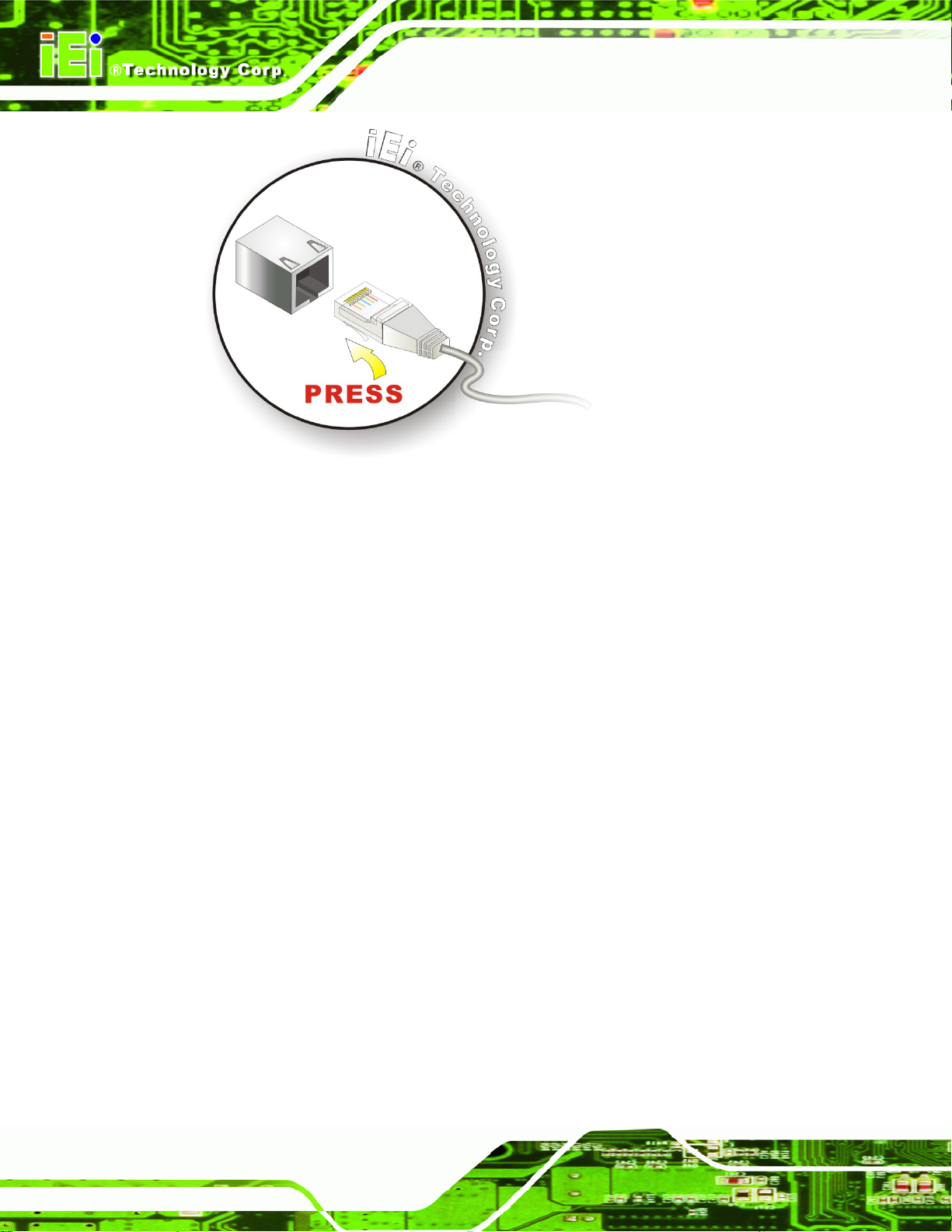
Figure 4-15: LAN Connection
Step 3: Insert the LAN cable RJ-45 connector. Once aligned, gently insert the LAN
KINO-G410 Mini-ITX Motherboard
cable RJ-45 connector into the on-board RJ-45 connector. Step 0:
4.6.4 Serial Device Connection
The KINO-G410 has three male DB-9 connectors on the external peripheral interface
panel for a serial device. Follow the steps below to connect a serial device to the
KINO-G410.
Step 1: Locate the DB-9 connector. The location of the DB-9 connector is shown in
Chapter 3.
Step 2: Insert the serial connector. Insert the DB-9 connector of a serial device into
the DB-9 connector on the external peripheral interface. See
Figure 4-16.
Page 52
Page 65

KINO-G410 Mini-ITX Motherboard
Figure 4-16: Serial Device Connector
Step 3: Secure the connector. Secure the serial device connector to the external
interface by tightening the two retention screws on either side of the connector.
4.6.5 USB Device Connection
The external USB Series "A" receptacle connectors provide easier and quicker access to
external USB devices. Follow the steps below to connect USB devices to the KINO-G410.
Step 1: Locate the USB Series "A" receptacle connectors. The location of the USB
Series "A" receptacle connectors are shown in Chapter 3.
Step 2: Insert a USB Series "A" plug. Insert the USB Series "A" plug of a device into
the USB Series "A" receptacle on the external peripheral interface. See
Figure 4-17.
Step 0:
Page 53
Page 66

KINO-G410 Mini-ITX Motherboard
Figure 4-17: USB Connector
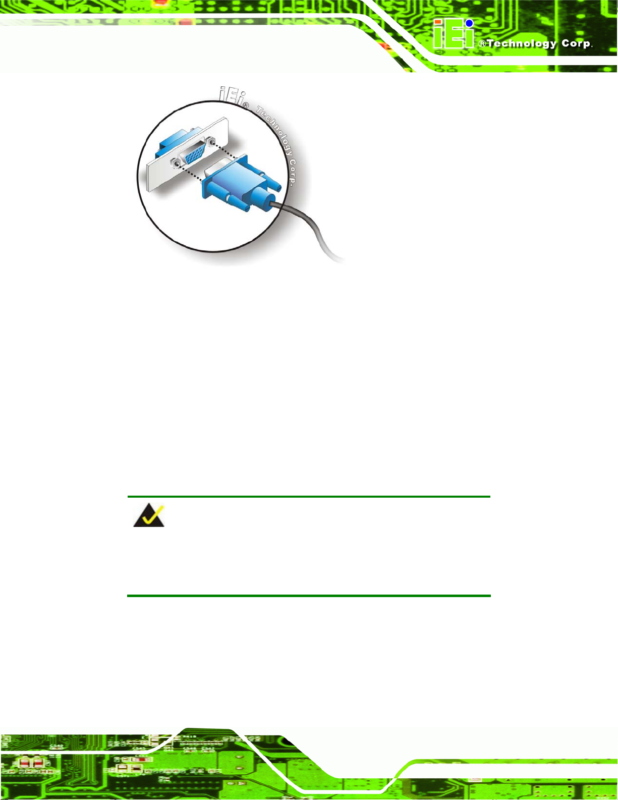
4.6.6 VGA Monitor Connection
The KINO-G410 has a single female DB-15 connector on the external peripheral interface
panel. The DB-15 connector is connected to a CRT or VGA monitor. To connect a monitor
to the KINO-G410, please follow the instructions below.
Step 1: Locate the female DB-15 connector. The location of the female DB-15
connector is shown in Chapter 3.
Step 2: Align the VGA connector. Align the male DB-15 connector on the VGA screen
cable with the female DB-15 connector on the external peripheral interface.
Step 3: Insert the VGA connector. Once the conne ctors are prop erly aligned with the
insert the male connector from the VGA screen into the female connector on the
Page 54
KINO-G410. See
Figure 4-18.
Page 67
KINO-G410 Mini-ITX Motherboard
Figure 4-18: VGA Connector
Step 4: Secure the connector. Secure the DB-15 VGA connector from the VGA
monitor to the external interface by tightening the two retention screws on either
side of the connector. Step 0:
4.7 Software Installation
All the drivers for the KINO-G410 are on the CD that came with the system. To install the
drivers, please follow the steps below.
Step 1: Insert the CD into a CD drive connected to the system.
NOTE:
If the installation program doesn't start automatically:
Click "Start->My Computer->CD Drive->autorun.exe"
Step 2: The driver main menu appears.
Step 3: Click KINO-G410.
Step 4: A new screen with a list of available drivers appears.
Step 5: Install all of the necessary drivers in this menu. Step 0:
Page 55
Page 68

KINO-G410 Mini-ITX Motherboard
Chapter
5
5 BIOS
Page 56
Page 69
KINO-G410 Mini-ITX Motherboard
5.1 Introduction
The BIOS is programmed onto the BIOS chip. The BIOS setup program allows changes to
certain system settings. This chapter outlines the options that can be changed.
5.1.1 Starting Setup
The UEFI BIOS is activated when the computer is turned on. The setup program can be
activated in one of two ways.
1. Press the
2. Press the
the screen. 0.
If the message disappears before the F2 key is pressed, restart the computer and try
again.
F2 key as soon as the system is turned on or
F2 key when the “Press F2 to enter SETUP” message appears on
5.1.2 Using Setup
Use the arrow keys to highlight items, press ENTER to select, use the PageUp and
PageDown keys to change entries, press F1 for help and press E
keys are shown in.
Key Function
Up arrow Move to the item above
Down arrow Move to the item below
Left arrow Move to the item on the left hand side
SC to quit. Navigation
Right arrow Move to the item on the right hand side
+ Increase the numeric value or make changes
- Decrease the numeric value or make changes
Page up Move to the next page
Page down Move to the previous page
Page 57
Page 70

Key Function
Esc Main Menu – Quit and do not save changes into CMOS
F1 General help, only for S t atus Page Setup Menu and Option
F9 Load optimized defaults
F10 Save changes and Exit BIOS
Table 5-1: BIOS Navigation Keys
5.1.3 Getting Help
When F1 is pressed a small help window describing the appropriate keys to use and the
KINO-G410 Mini-ITX Motherboard
Status Page Setup Menu and Option Page Setup Menu -Exit current page and return to Main Menu
Page Setup Menu
possible selections for the highlighted item appears. To exit the Help Window press E
the F1 key again.
5.1.4 Unable to Reboot after Configuration Changes
If the computer cannot boot after changes to the system configuration is made, CMOS
defaults. Use the jumper described in Chapter
4.
5.1.5 BIOS Menu Bar
The menu bar on top of the BIOS screen has the following main items:
Main – Changes the basic system configuration.
Advanced – Changes the advanced system settings.
PCIPnP – Changes the advanced PCI/PnP Settings
Boot – Changes the system boot configuration.
Security – Sets User and Supervisor Passwords.
Chipset – Changes the chipset settings.
SC or
Page 58
Exit – Selects exit options and loads default settings
The following sections completely describe the configuration options found in the menu
items at the top of the BIOS screen and listed above.
Page 71

KINO-G410 Mini-ITX Motherboard
5.2 Main
The Main BIOS menu (BIOS Menu 1) appears when the BIOS Setup program is entered.
The Main menu gives an overview of the basic system information.
BIOS SETUP UTILITY
Main Advanced PCIPNP Boot Security Chipset Exit
System Overview
⎯⎯⎯⎯⎯⎯⎯⎯⎯⎯⎯⎯⎯⎯⎯⎯⎯⎯⎯⎯⎯⎯⎯⎯⎯⎯⎯⎯⎯⎯⎯
AMIBIOS
Version :08.00.15
Build Date :06/03/10
ID: :SA16T057
Processor
Type :Intel® Core™2 CPU E8400 @ 3.00GHz
Speed :3000MHz
Count :1
System Memory
Size :990MB
System Time [14:20:27]
System Time [Tue 010/08/2009]
v02.61 ©Copyright 1985-2006, American Megatrends, Inc.
Select Screen
↑ ↓ Select Item
Enter Go to SubScreen
F1 General Help
F10 Save and Exit
ESC Exit
BIOS Menu 1: Main
System Overview
The System Overvie w lists a brief summary of different system components. Th e fields in
System Overview cannot be changed. The items shown in the system overview include:
AMI BIOS: Displays auto-detected BIOS information
o Version: Current BIOS version
o Build Date: Date the current BIOS version was made
o ID: Installed BIOS ID
Processor: Displays auto-detected CPU specifications
o Type: Names the currently installed processor
o Speed: Lists the processor speed
o Count: The number of CPUs on the motherboard
System Memory: Displays the auto-detected system memory.
o Size: Lists memory size
Page 59
Page 72

The System Overview field also has two user configurable fields:
System Time [xx:xx:xx]
Use the System Time option to set the system time. Manually enter the hours, minutes
and seconds.
System Date [xx/xx/xx]
Use the System Date option to set the system date. Manually enter the day, month and
year.
5.3 Advanced
Use the Advanced menu (BIOS Menu 2) to configure the CPU and peripheral devices
through the following sub-menus:
KINO-G410 Mini-ITX Motherboard
WARNING!
Setting the wrong values in the sections below may cause the system
to malfunction. Make sure that the settings made are compatible with
the hardware.
CPU Configuration (see Section 5.3.1)
IDE Configuration (see Section
Super IO Configuration (see Section
Hardware Health Configuration (see Section
Power Configuration (see Section
Remote Access Configuration (see Section
USB Configuration (see Section
5.3.2)
5.3.3)
5.3.4)
5.3.5)
5.3.6)
5.3.7)
Page 60
Page 73

KINO-G410 Mini-ITX Motherboard
BIOS SETUP UTILITY
Main Advanced PCIPNP Boot Security Chipset Exit
Advanced Settings
⎯⎯⎯⎯⎯⎯⎯⎯⎯⎯⎯⎯⎯⎯⎯⎯⎯⎯⎯⎯⎯⎯⎯⎯⎯⎯⎯⎯⎯⎯⎯
WARNING: Setting wrong values in below sections may cause
system to malfunction
> CPU Configuration
> IDE Configuration
> SuperIO Configuration
> Hardware Health Configuration
> Power Configuration
> Remote Access Configuration
> USB Configuration
v02.61 ©Copyright 1985-2006, American Megatrends, Inc.
BIOS Menu 2: Advanced
Select Screen
↑ ↓ Select Item
Enter Go to SubScreen
F1 General Help
F10 Save and Exit
ESC Exit
5.3.1 CPU Configuration
Use the CPU Configuration menu (BIOS Menu 3) to view detailed CPU specifications
and configure the CPU.
BIOS SETUP UTILITY
Main Advanced PCIPNP Boot Security Chipset Exit
Configure Advanced CPU Settings
Module Version:3F.15
⎯⎯⎯⎯⎯⎯⎯⎯⎯⎯⎯⎯⎯⎯⎯⎯⎯⎯⎯⎯⎯⎯⎯⎯⎯⎯⎯⎯⎯⎯⎯
Manufacturer :Intel®
Intel® Core™2 CPU E8400 @ 3.00GHz
Frequency :3.00GHz
FSB Speed :1333MHz
Cache L1 :64 KB
Cache L2 :6144 KB
Ratio Actual Value:9
v02.61 ©Copyright 1985-2006, American Megatrends, Inc.
BIOS Menu 3: CPU Configuration
Select Screen
↑ ↓ Select Item
Enter Go to SubScreen
F1 General Help
F10 Save and Exit
ESC Exit
The CPU Configuration menu (BIOS Menu 3) lists the following CPU details:
Manufacturer: Lists the name of the CPU manufacturer
Brand String: Lists the brand name of the CPU being used
Page 61
Page 74
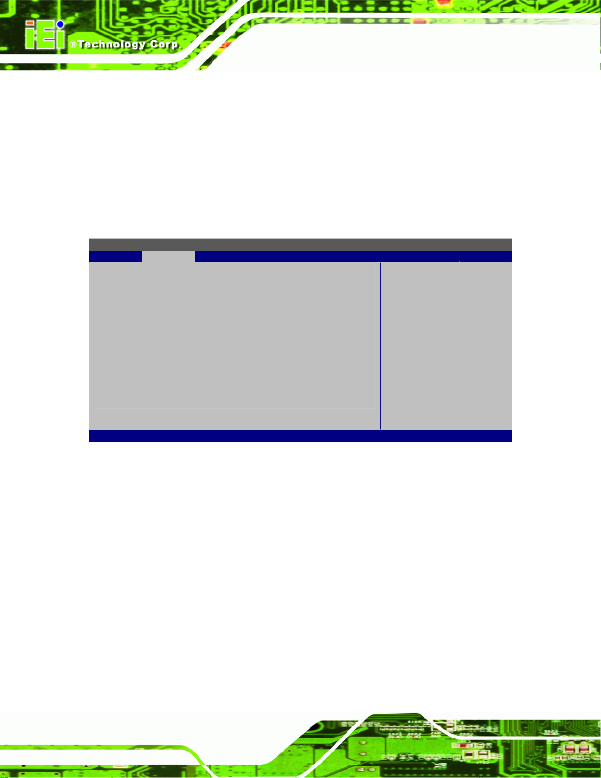
Frequency: Lists the CPU processing speed
FSB Speed: Lists the FSB speed
Cache L1: Lists the CPU L1 cache size
Cache L2: Lists the CPU L2 cache size
KINO-G410 Mini-ITX Motherboard
5.3.2 IDE Configuration
Use the IDE Configuration menu (BIOS Menu 4) to change and/or set the configuration
of the IDE devices installed in the system.
BIOS SETUP UTILITY
Main Advanced PCIPNP Boot Security Chipset Exit
IDE Configuration
⎯⎯⎯⎯⎯⎯⎯⎯⎯⎯⎯⎯⎯⎯⎯⎯⎯⎯⎯⎯⎯⎯⎯⎯⎯⎯⎯⎯⎯⎯⎯
ATA/IDE Configuration [Enhanced]
Configure SATA as [IDE]
> Primary IDE Master : [Not Detected]
> Primary IDE Slave : [Not Detected]
> Secondary IDE Master : [Not Detected]
> Secondary IDE Slave : [Not Detected]
> Third IDE Master : [Not Detected]
> Third IDE Slave : [Not Detected]
v02.61 ©Copyright 1985-2006, American Megatrends, Inc.
Select Screen
↑ ↓ Select Item
Enter Go to SubScreen
F1 General Help
F10 Save and Exit
ESC Exit
BIOS Menu 4: IDE Configuration
ATA/IDE Configurations [Enhanced]
Use the ATA/IDE Configurations option to configure the ATA/IDE controller.
Disabled
Compatible
Page 62
Disables the on-board ATA/IDE controller.
Configures the on-board ATA/IDE controller to be in
compatible mode. In this mode, a SATA channel will
replace one of the IDE channels. This mode supports
up to 4 storage devices.
Page 75

KINO-G410 Mini-ITX Motherboard
Enhanced DEFAULT
Configure SATA as [IDE]
Use the Configure SATA as option to configure SATA devices as normal IDE devices.
IDE DEFAULT
IDE Master and IDE Slave
When entering setup, BIOS automatically detects the presence of IDE devices. BIOS
displays the status of the automatically detected IDE devices. The following IDE devices
are detected and are shown in the IDE Configuration menu:
Configures SATA devices as normal IDE device.
Configures the on-board ATA/IDE controller to be in
Enhanced mode. In this mode, IDE channels and SATA
channels are separated. This mode supports up to 6
storage devices. Some legacy OS do not support this
mode.
Primary IDE Master
Primary IDE Slave
Secondary IDE Master
Secondary IDE Slave
Third IDE Master
Third IDE Slave
The IDE Configuration menu (
IDE devices installed in the system. If an IDE device is detected and one of the above
listed four BIOS configuration options are selected, the IDE configuration options shown in
Section
5.3.2.1 appear.
BIOS Menu 4) allows changes to the configurations for the
5.3.2.1 IDE Master, IDE Slave
Use the IDE Master and IDE Slave configuration menu to view both primary and
secondary IDE device details and configure the IDE devices connected to the system.
Page 63
Page 76

BIOS SETUP UTILITY
Main Advanced PCIPNP Boot Security Chipset Exit
Primary IDE Master
⎯⎯⎯⎯⎯⎯⎯⎯⎯⎯⎯⎯⎯⎯⎯⎯⎯⎯⎯⎯⎯⎯⎯⎯⎯⎯⎯⎯⎯⎯⎯
Device :Not Detected
Type [Auto]
LBA/Large Mode [Auto]
Block (Multi-Sector Transfer) [Auto]
PIO Mode [Auto]
DMA Mode [Auto]
S.M.A.R.T. [Auto]
32Bit Data Transfer [Enabled]
v02.61 ©Copyright 1985-2006, American Megatrends, Inc.
BIOS Menu 5: IDE Master and IDE Slave Configuration
Auto-Detected Drive Parameters
KINO-G410 Mini-ITX Motherboard
Select Screen
↑ ↓ Select Item
Enter Go to SubScreen
F1 General Help
F10 Save and Exit
ESC Exit
The “grayed-out” items in the left frame are IDE disk drive parameters automatically
detected from the firmware of the selected IDE disk drive. The drive parameters are listed
as follows:
Device: Lists the device type (e.g. hard disk, CD-ROM etc.)
Type: Indicates the type of devices a user ca n manually select
Vendor: Lists the device manufacturer
Size: List the storage capacity of the device.
LBA Mode: Indicates whether the LBA (Logical Block Addre s sing) is a method
of addressing data on a disk drive is supported or not.
Block Mode: Block mode boosts IDE drive performance by increasing the
amount of data transferred. Only 512 bytes of data can be transferred per
interrupt if block mode is not used. Block mode allows transfers of up to 64 KB
per interrupt.
PIO Mode: Indicates the PIO mode of the installed device.
Async DMA: Indicates the highest Asynchronous DMA Mode that is
supported.
Page 64
Ultra DMA: Indicates the highest Synchronous DMA Mode that is supported.
S.M.A.R.T.: Indicates whether or not the Self-Monitoring Analysis and
Reporting Technology protocol is supported.
Page 77

KINO-G410 Mini-ITX Motherboard
32Bit Data Transfer: Enables 32-bit data transfer.
Type [Auto]
Use the Type BIOS option select the type of device the AMIBIOS attempts to boot from
after the Power-On Self-Test (POST) is complete.
Not Installed
Auto DEFAULT
CD/DVD
ARMD
BIOS is prevented from searching for an IDE disk
drive on the specified channel.
The BIOS automatically detects the IDE disk drive
type attached to the specified channel. This setting
should be used if an IDE hard disk drive is atta ch ed t o
the specified channel.
The CD/DVD option specifies that an IDE CD-ROM
drive is attached to the specified IDE channel. The
BIOS does not attempt to search for other types of
IDE disk drives on the specified channel.
This option specifies an ATAPI Removable Media
Device. These include, but are not limited to:
ZIP
LS-120
LBA/Large Mode [Auto]
Use the LBA/Large Mode option to disable or enable BIOS to auto detects LBA (Logical
Block Addressing). LBA is a method of addressing data on a disk drive. In LBA mode, the
maximum drive capacity is 137 GB.
Disabled
Auto DEFAULT
BIOS is prevented from using the LBA mode control on
the specified channel.
BIOS auto detects the LBA mode control on the specified
channel.
Page 65
Page 78

Block (Multi Sector Transfer) [Auto]
Use the Block (Multi Sector Transfer) to disable or enable BIOS to auto detect if the
device supports multi-sector transfers.
KINO-G410 Mini-ITX Motherboard
Disabled
Auto DEFAULT
PIO Mode [Auto]
Use the PIO Mode option to select the IDE PIO (Programmable I/O) mode program timing
cycles between the IDE drive and the programmable IDE controller. As the PIO mode
increases, the cycle time decrease s.
Auto DEFAULT
0
BIOS is prevented from using Multi-Sector T ran sfer on the
specified channel. The data to and from the device occurs
one sector at a time.
BIOS auto detects Multi-Sector Transfer support on the
drive on the specified channel. If supported the data
transfer to and from the device occurs multiple sectors at
a time.
BIOS auto detects the PIO mode. Use this value if the IDE disk
drive support cannot be determined.
PIO mode 0 selected with a maximum transfer rate of 3.3 MB/s
1
2
3
4
DMA Mode [Auto]
Use the DMA Mode BIOS selection to adjust the DMA mode options.
Page 66
PIO mode 1 selected with a maximum transfer rate of 5.2 MB/s
PIO mode 2 selected with a maximum transfer rate of 8.3 MB/s
PIO mode 3 selected with a maximum transfer rate of 11.1 MB/s
PIO mode 4 selected with a maximum transfer rate of 16.6 MB/s
(This setting generally works with all hard disk drives
manufactured after 1999. For other disk drives, such as IDE
CD-ROM drives, check the specifications of the drive.)
Page 79

KINO-G410 Mini-ITX Motherboard
Auto DEFAULT
S.M.A.R.T [Auto]
Use the S.M.A.R.T option to auto-detect, disable or enable Self-Monitoring Analysis and
Reporting Technology (SMART) on the drive on the specified channel. S.M.A.R.T predicts
impending drive failures. The S.M.A.R.T BIOS option enables or disables this function.
Auto DEFAULT
Disabled
Enabled
32Bit Data Transfer [Enabled]
Use the 32Bit Data Transfer BIOS option to enables or disable 32-bit data transfers.
BIOS auto detects the DMA mode. Use this value if the IDE
disk drive support cannot be determined.
BIOS auto detects HDD SMART support.
Prevents BIOS from using the HDD SMART feature.
Allows BIOS to use the HDD SMART feature
Disabled
Enabled DEFAULT
Prevents the BIOS from using 32-bit data transfers.
Allows BIOS to use 32-bit data transfers on supported
hard disk drives.
5.3.3 Super IO Configuration
Use the Super IO Configuration menu (BIOS Menu 6) to set or change the
configurations for the FDD controllers, parallel ports and serial ports.
Page 67
Page 80

BIOS SETUP UTILITY
Main Advanced PCIPNP Boot Security Chipset Exit
Super I/O Chipset
⎯⎯⎯⎯⎯⎯⎯⎯⎯⎯⎯⎯⎯⎯⎯⎯⎯⎯⎯⎯⎯⎯⎯⎯⎯⎯⎯⎯⎯⎯⎯
Serial Port1 Address [3F8]
Serial Port1 IRQ [IRQ4]
Serial Port2 Address [2F8]
Serial Port2 IRQ [IRQ3]
Serial Port3 Address [3E8]
Serial Port3 IRQ [IRQ11]
Serial Port4 Address [2E8]
Serial Port4 IRQ [IRQ10]
Serial Port5 Address [3E0]
Serial Port5 IRQ [IRQ11]
Serial Port6 Address [2E0]
Serial Port6 IRQ [IRQ10]
Parallel Port Address [378]
Parallel Port Mode [Normal]
Parallel Port IRQ [IRQ7]
v02.61 ©Copyright 1985-2006, American Megatrends, Inc.
KINO-G410 Mini-ITX Motherboard
Select Screen
↑ ↓ Select Item
Enter Go to SubScreen
F1 General Help
F10 Save and Exit
ESC Exit
BIOS Menu 6: Super IO Configuration
Serial Port1 Address [3F8]
Use the Serial Port1 Address option to select the Serial Port 1 base address.
Disabled
3F8 DEFAULT
2F8
Serial Port1 IRQ [IRQ4]
Use the Serial Port1 IRQ option to select the Serial Port 1 interrupt address.
IRQ3
IRQ4 DEFAULT
No base address is assigned to Serial Port 1
Serial Port 1 I/O port address is 3F8
Serial Port 1 I/O port address is 2F8
IRQ3 is assigned as the Serial Port 1 interrupt address
IRQ4 is assigned as the Serial Port 1 interrupt address
Page 68
Page 81
KINO-G410 Mini-ITX Motherboard
Serial Port2 Address [2F8]
Use the Serial Port2 Address option to select the Serial Port 2 base address.
Disabled
3F8
2F8 DEFAULT
Serial Port2 IRQ [IRQ3]
Use the Serial Port2 IRQ option to select the Serial Port 2 interrupt address.
IRQ3 DEFAULT
IRQ4
Serial Port3 Address [3E8]
Use the Serial Port3 Address option to select the Serial Port 3 base address.
Disabled
3E8 DEFAULT
No base address is assigned to Serial Port 2
Serial Port 2 I/O port address is 3F8
Serial Port 2 I/O port address is 2F8
IRQ3 is assigned as the Serial Port 2 interrupt address
IRQ4 is assigned as the Serial Port 2 interrupt address
No base address is assigned to Serial Port 3
Serial Port 3 I/O port address is 3E8
2E8
Serial Port3 IRQ [IRQ11]
Use the Serial Port3 IRQ option to select the Serial Port 3 interrupt address.
IRQ10
IRQ11 DEFAULT
Serial Port4 Address [2E8]
Use the Serial Port4 Address option to select the Serial Port 4 base address.
Disabled
3E8
Serial Port 3 I/O port address is 2E8
IRQ10 is assigned as the Serial Port 3 interrupt address
IRQ11 is assigned as the Serial Port 3 interrupt address
No base address is assigned to Serial Port 4
Serial Port 4 I/O port address is 3E8
Page 69
Page 82

KINO-G410 Mini-ITX Motherboard
2E8 DEFAULT
Serial Port4 IRQ [IRQ10]
Use the Serial Port4 IRQ option to select the Serial Port 4 interrupt address.
IRQ10 DEFAULT
IRQ11
Serial Port5 Address [3E0]
Use the Serial Port5 Address option to select the Serial Port 5 base address.
Disabled
3E0 DEFAULT
2E0
Serial Port 4 I/O port address is 2E8
IRQ10 is assigned as the Serial Port 4 interrupt address
IRQ11 is assigned as the Serial Port 4 interrupt address
No base address is assigned to Serial Port 5
Serial Port 5 I/O port address is 3E0
Serial Port 5 I/O port address is 2E0
Serial Port5 IRQ [IRQ11]
Use the Serial Port5 IRQ option to select the Serial Port 5 interrupt address.
IRQ10
IRQ11 DEFAULT
Serial Port6 Address [2E0]
Use the Serial Port6 Address option to select the Serial Port 6 base address.
Disabled
3E0
2E0 DEFAULT
IRQ10 is assigned as the Serial Port 5 interrupt address
IRQ11 is assigned as the Serial Port 5 interrupt address
No base address is assigned to Serial Port 6
Serial Port 6 I/O port address is 3E0
Serial Port 6 I/O port address is 2E0
Page 70
Page 83

KINO-G410 Mini-ITX Motherboard
Serial Port6 IRQ [IRQ10]
Use the Serial Port6 IRQ option to select the Serial Port 6 interrupt address.
IRQ10 DEFAULT
IRQ11
Parallel Port Address [378]
Use the Parallel Port Address option to select the parallel port base address.
Disabled
378 DEFAULT
278
3BC
Parallel Port Mode [Normal]
Use the Parallel Port Mode option to select the mode the parallel port operates in.
Normal DEFAULT
IRQ10 is assigned as the Serial Port 6 interrupt address
IRQ11 is assigned as the Serial Port 6 interrupt address
No base address is assigned to the Parallel Port
Parallel Port I/O port address is 378
Parallel Port I/O port address is 278
Parallel Port I/O port address is 3BC
The normal parallel port mode is the standard mode
for parallel port operation.
Bi-directional
EPP
Parallel port outputs are 8-bits long. Inputs are
accomplished by reading 4 of the 8 bits on the
status register.
The parallel port operates in the enhanced parallel
port mode (EPP). The EPP mode supports
bi-directional communication between the system
and the parallel port device and the transmission
rates between the two are much faster than the
Normal mode.
Page 71
Page 84

KINO-G410 Mini-ITX Motherboard
ECP+EPP
Parallel Port IRQ [IRQ7]
Use the Parallel Port IRQ selection to set the parallel port interrupt address.
IRQ5
IRQ7 DEFAULT
IRQ5 is assigned as the parallel port interrupt address
IRQ7 is assigned as the parallel port interrupt address
The parallel port operates in the extended
capabilities port (ECP) mode. The ECP mode
supports bi-directional communication between the
system and the parallel port device and the
transmission rates between the two are much faster
than the Normal mode
The parallel port is also be compatible with EPP
devices described above
Page 72
Page 85

KINO-G410 Mini-ITX Motherboard
5.3.4 Hardware Health Configuration
The Hardware Health Configuration menu (BIOS Menu 7) shows the operating
temperature, fan speeds and system voltages.
BIOS SETUP UTILITY
Main Advanced PCIPNP Boot Security Chipset Exit
Hardware Health Event Monitoring
⎯⎯⎯⎯⎯⎯⎯⎯⎯⎯⎯⎯⎯⎯⎯⎯⎯⎯⎯⎯⎯⎯⎯⎯⎯⎯⎯⎯⎯⎯⎯
FAN1 Mode Setting [Auto Fan by RPM]
Temperature 1 Limit if Highe [050]
Temperature 1 Limit if Secon [040]
Temperature 1 Limit if Third [030]
Temperature 1 Limit if Lowes [020]
Fan 1 Highest Setting [100]
Fan 1 Second Setting [080]
Fan 1 Third Setting [070]
Fan 1 Fourth Setting [060]
Fan 1 Lowest Setting [050]
⎯⎯⎯⎯⎯⎯⎯⎯⎯⎯⎯⎯⎯⎯⎯⎯⎯⎯⎯⎯⎯⎯⎯⎯⎯⎯⎯⎯⎯⎯⎯
CPU Temperature :74ºC/165ºF
System Temperature :45ºC/113ºF
CPU Fan Speed :1783 RPM
VCC3 :3.312 V
VCC_Core :1.232 V
VTN_1.5V :1.552 V
VTN2_5V :5.016 V
VTN3_12V :12.320 V
VSB :3.456 V
VBAT :3.056 V
v02.61 ©Copyright 1985-2006, American Megatrends, Inc.
Select Screen
↑ ↓ Select Item
Enter Go to SubScreen
F1 General Help
F10 Save and Exit
ESC Exit
BIOS Menu 7: Hardware Health Configuration
Fan1 Mode Setting [Auto Fan by RPM]
Use the Mode Setting option to configure the fan.
Page 73
Page 86

KINO-G410 Mini-ITX Motherboard
Auto Fan by RPM DEFAULT
Auto Fan by
DutyCycle
The fan adjusts its speed using these settings:
Temperature 1 Limit if Highest
Temperature 1 Limit if Second
Temperature 1 Limit if Third
Temperature 1 Limit if Lowest
Fan 1 Highest Setting
Fan 1 Second Setting
Fan 1 Third Setting
Fan 1 Fourth Setting
Fan 1 Lowest Setting
The fan adjusts its speed using these settings:
Temperature 1 Limit if Highest
Temperature 1 Limit if Second
Temperature 1 Limit if Third
Temperature 1 Limit if Lowest
Fan 1 Highest Setting
Fan 1 Second Setting
Fan 1 Third Setting
Fan 1 Fourth Setting
Fan 1 Lowest Setting
Manual Mode by
RPM
Manual Mode by
DutyCycle
Hardware Health Monitoring
The following system parameters and values are shown. The system parameters that are
monitored are:
The fan spins at the speed set in:
Manual RPM Setting
The fan spins at the speed set in:
Manual Duty Cycle Setting
Page 74
System Temperatures:
Page 87

KINO-G410 Mini-ITX Motherboard
o CPU Temperature
o System Temperature
Fan Speeds:
o CPU Fan Speed
o SYS Fan Speed
Voltages:
o VCC3
o VCC_Core
o VTN_1.5V
o VTN2_5V
o VTN3_12V
o VSB
o VBAT
5.3.5 Power Configuration
Use the Power Configuration menu (BIOS Menu 9) configures the Advanced
Configuration and Power Interface (ACPI) and Power Management (APM) options.
BIOS SETUP UTILITY
Main Advanced PCIPNP Boot Security Chipset Exit
Select AT/ATX Power [ATX Power]
⎯⎯⎯⎯⎯⎯⎯⎯⎯⎯⎯⎯⎯⎯⎯⎯⎯⎯⎯⎯⎯⎯⎯⎯⎯⎯⎯⎯⎯⎯⎯
> ACPI Configuration
Select Screen
↑ ↓ Select Item
Enter Go to SubScreen
F1 General Help
F10 Save and Exit
ESC Exit
v02.61 ©Copyright 1985-2006, American Megatrends, Inc.
BIOS Menu 8: ACPI Configuration
Page 75
Page 88

KINO-G410 Mini-ITX Motherboard
5.3.5.1 ACPI Settings
Use the General ACPI Settings menu (BIOS Menu 9) to select the ACPI state when the
system is suspended.
BIOS SETUP UTILITY
Main Advanced PCIPNP Boot Security Chipset Power Exit
ACPI Settings
⎯⎯⎯⎯⎯⎯⎯⎯⎯⎯⎯⎯⎯⎯⎯⎯⎯⎯⎯⎯⎯⎯⎯⎯⎯⎯⎯⎯⎯⎯⎯
Suspend mode [S1 (POS)]
Select Screen
↑ ↓ Select Item
Enter Go to SubScreen
F1 General Help
F10 Save and Exit
ESC Exit
v02.61 ©Copyright 1985-2006, American Megatrends, Inc.
BIOS Menu 9: ACPI Settings
Suspend Mode [S1(POS)]
Use the Suspend Mode option to specify the sleep state the system enters when it is not
being used.
S1 (POS) DEFAULT
S3 (STR)
The system enters S1 (POS) sleep state. The system
appears off. The CPU is stopped; RAM is refreshed; the
system is running in a low power mode.
5.3.6 Remote Access Configuration
Use the Remote Access Configuration menu (BIOS Menu 10) to configure remote
access parameters. The Remote Access Configuration is an AMIBIOS feature and
allows a remote host running a terminal program to display and configure the BIOS
Page 76
settings.
Page 89

KINO-G410 Mini-ITX Motherboard
BIOS SETUP UTILITY
Main Advanced PCIPNP Boot Security Chipset Exit
Configure Remote Access type and parameters
⎯⎯⎯⎯⎯⎯⎯⎯⎯⎯⎯⎯⎯⎯⎯⎯⎯⎯⎯⎯⎯⎯⎯⎯⎯⎯⎯⎯⎯⎯⎯
Remote Access [Disabled]
Select Screen
↑ ↓ Select Item
Enter Go to SubScreen
F1 General Help
F10 Save and Exit
ESC Exit
v02.61 ©Copyright 1985-2006, American Megatrends, Inc.
BIOS Menu 10: Remote Access Configuration
Remote Access [Disabled]
Use the Remote Access option to enable or disable access to the remote functionalities
of the system.
Disabled DEFAULT
Enabled
Serial Port Number [COM1]
Use the Serial Port Number option to select the serial port used for remote access.
Remote access is disabled.
Remote access configuration options shown below
appear:
Serial Port Number
Serial Port Mode
Redirection after BIOS POST
Terminal Type
These configuration options are discussed below.
COM1 DEFAULT
COM2
System is remotely accessed through COM1
System is remotely accessed through COM2
Page 77
Page 90

KINO-G410 Mini-ITX Motherboard
COM3
COM4
COM5
COM6
NOTE: Make sure the selected COM port is enabled through the Super I/O configuration
menu.
Base Address, IRQ [3F8h,4]
The Base Address, IRQ option cannot be configured and only shows the interrupt
address of the serial port listed above.
Serial Port Mode [115200 8,n,1]
Use the Serial Port Mode option to select baud rate through which the console redirection
is made. The following configuration options are available
System is remotely accessed through COM3
System is remotely accessed through COM4
System is remotely accessed through COM5
System is remotely accessed through COM6
115200 8,n,1 D
57600 8,n,1
38400 8,n,1
19200 8,n,1
09600 8,n,1
EFAULT
NOTE:
Identical baud rate setting musts be set on the host (a management
computer running a terminal software) and the slave
Redirection After BIOS POST [Always]
Use the Redirection After BIOS POST option to specify when console redirection should
occur.
Disabled
The console is not redirected after POST
Page 78
Page 91

KINO-G410 Mini-ITX Motherboard
Boot Loader
Always DEFAULT
Terminal Type [ANSI]
Use the Terminal Type BIOS option to specify the remote terminal type.
ANSI DEFAULT
VT100
VT-UTF8
Redirection is active during POST and during Boot
Loader
Redirection is always active (Some OSes may not
work if set to Always)
The target terminal type is ANSI
The target terminal type is VT100
The target terminal type is VT-UTF8
5.3.7 USB Configuration
Use the USB Configuration menu (BIOS Menu 11) to read USB configuration
information and configure the USB settings.
BIOS SETUP UTILITY
Main Advanced PCIPNP Boot Security Chipset Exit
USB Configuration
⎯⎯⎯⎯⎯⎯⎯⎯⎯⎯⎯⎯⎯⎯⎯⎯⎯⎯⎯⎯⎯⎯⎯⎯⎯⎯⎯⎯⎯⎯⎯
Module Version – 2.24.3-13.4
USB Devices Enabled:
None
USB Functions [Enabled]
USB 2.0 Controller [Enabled]
Legacy USB Support [Enabled]
USB 2.0 Controller Mode [HiSpeed]
v02.61 ©Copyright 1985-2006, American Megatrends, Inc.
BIOS Menu 11: USB Configuration
Select Screen
↑ ↓ Select Item
Enter Go to SubScreen
F1 General Help
F10 Save and Exit
ESC Exit
Page 79
Page 92

USB Configuration
The USB Configuration field shows the system USB configuration. The items listed are:
Module Version: x.xxxxx.xxxxx
USB Devices Enabled
The USB Devices Enabled field lists the USB devices that are enabled on the system
USB Function [Enabled]
Use the USB Function BIOS option to enable or disable USB function support.
KINO-G410 Mini-ITX Motherboard
Disabled
Enabled DEFAULT
USB 2.0 Controller [Enabled]
Use the USB 2.0 Controller BIOS option to enable or disable the USB 2.0 controller
Enabled DEFAULT
Disabled
Legacy USB Support [Enabled]
Use the Legacy USB Support BIOS option to enable USB mouse and USB keyboard
support.
Normally if this option is not enabled, any attached USB mouse or USB keyboard does not
become available until a USB compatible operating system is fully booted with all USB
USB function support disabled
USB function support enabled
USB 2.0 controller enabled
USB 2.0 controller disabled
Page 80
drivers loaded. When this option is enabled, any attached USB mouse or USB keyboard
can control the system even when there is no USB driver loaded onto the system.
Disabled
Enabled DEFAULT
Legacy USB support disabled
Legacy USB support enabled
Page 93

KINO-G410 Mini-ITX Motherboard
Auto
USB2.0 Controller Mode [HiSpeed]
Use the USB2.0 Controller Mode option to set the speed of the USB2.0 controller.
FullSpeed
HiSpeed DEFAULT
5.4 PCI/PnP
Use the PCI/PnP menu (BIOS Menu 12) to configure advanced PCI and PnP settings.
WARNING!
Setting wrong values for the BIOS selections in the PCIPnP BIOS
Legacy USB support disabled if no USB devices are
connected
The controller is capable of operating at 12 Mb/s
The controller is capable of operating at 480 Mb/s
menu may cause the system to malfunction.
Page 81
Page 94

BIOS SETUP UTILITY
Main Advanced PCIPNP Boot Security Chipset Exit
Advanced PCI/PnP Settings
⎯⎯⎯⎯⎯⎯⎯⎯⎯⎯⎯⎯⎯⎯⎯⎯⎯⎯⎯⎯⎯⎯⎯⎯⎯⎯⎯⎯⎯⎯⎯
WARNING: Setting wrong values in below sections
may cause system to malfunction
IRQ3 [Reserved]
IRQ4 [Reserved]
IRQ5 [Available]
IRQ7 [Available]
IRQ9 [Available]
IRQ10 [Reserved]
IRQ11 [Reserved]
IRQ14 [Available]
IRQ15 [Available]
DMA Channel 0 [Available]
DMA Channel 1 [Available]
DMA Channel 3 [Available]
DMA Channel 5 [Available]
DMA Channel 6 [Available]
DMA Channel 7 [Available]
Reserved Memory Size [Disabled]
v02.61 ©Copyright 1985-2006, American Megatrends, Inc.
KINO-G410 Mini-ITX Motherboard
Select Screen
↑ ↓ Select Item
Enter Go to SubScreen
F1 General Help
F10 Save and Exit
ESC Exit
BIOS Menu 12: PCI/PnP Configuration
IRQ# [Available]
Use the IRQ# address to specify what IRQs can be assigned to a particular peripheral
device.
Available DEFAULT
Reserved
Available IRQ addresses are:
IRQ3
IRQ4
IRQ5
The specified IRQ is available to be used by
PCI/PnP devices
The specified IRQ is reserved for use by Legacy ISA
devices
Page 82
IRQ7
Page 95

KINO-G410 Mini-ITX Motherboard
IRQ9
IRQ10
IRQ 11
IRQ 14
IRQ 15
DMA Channel# [Available]
Use the DMA Channel# option to assign a specific DMA channel to a particular PCI/PnP
device.
Available DEFAULT
Reserved
Available DMA Channels are:
DM Channel 0
DM Channel 1
DM Channel 3
DM Channel 5
DM Channel 6
DM Channel 7
Reserved Memory Size [Disabled]
Use the Reserved Memory Size BIOS option to specify the amount of memory that
The specified DMA is available to be used by
PCI/PnP devices
The specified DMA is reserved for use by Legacy
ISA devices
should be reserved for legacy ISA devices.
Disabled DEFAULT
16K
32K
64K
No memory block reserved for legacy ISA devices
16 KB reserved for legacy ISA devices
32 KB reserved for legacy ISA devices
54 KB reserved for legacy ISA devices
Page 83
Page 96

KINO-G410 Mini-ITX Motherboard
5.5 Boot
Use the Boot menu (BIOS Menu 13) to configure system boot options.
BIOS SETUP UTILITY
Main Advanced PCIPNP Boot Security Chipset Exit
Boot Settings
⎯⎯⎯⎯⎯⎯⎯⎯⎯⎯⎯⎯⎯⎯⎯⎯⎯⎯⎯⎯⎯⎯⎯⎯⎯⎯⎯⎯⎯⎯⎯
> Boot Settings Configuration
Select Screen
↑ ↓ Select Item
Enter Go to SubScreen
F1 General Help
F10 Save and Exit
ESC Exit
v02.61 ©Copyright 1985-2006, American Megatrends, Inc.
BIOS Menu 13: Boot
5.5.1 Boot Settings Configuration
Use the Boot Settings Configuration menu (BIOS Menu 14) to configure advanced
system boot options.
BIOS SETUP UTILITY
Main Advanced PCIPNP Boot Security Chipset Exit
Boot Settings Configuration
⎯⎯⎯⎯⎯⎯⎯⎯⎯⎯⎯⎯⎯⎯⎯⎯⎯⎯⎯⎯⎯⎯⎯⎯⎯⎯⎯⎯⎯⎯⎯
Quick Boot [Enabled]
Quiet Boot [Disabled]
AddOn ROM Display Mode [Force BIOS]
Bootup Num-Lock [On]
Boot From LAN Support [Disabled]
v02.61 ©Copyright 1985-2006, American Megatrends, Inc.
Select Screen
↑ ↓ Select Item
Enter Go to SubScreen
F1 General Help
F10 Save and Exit
ESC Exit
Page 84
BIOS Menu 14: Boot Settings Configuration
Page 97

KINO-G410 Mini-ITX Motherboard
Quick Boot [Enabled]
Use the Quick Boot BIOS option to make the computer speed up the boot process.
Disabled
Enabled DEFAULT
Quiet Boot [Disabled]
Use the Quiet Boot BIOS option to select the screen display when the system boots.
Disabled DEFAULT
Enabled
AddOn ROM Display Mode [Force BIOS]
Use the AddOn ROM Display Mode option to allow add-on ROM (read-only memory)
messages to be displayed.
Force BIOS DEFAULT
No POST procedures are skipped
Some POST procedures are skipped to decrease
the system boot time
Normal POST messages displayed
OEM Logo displayed instead of POST messages
The system forces third party BIOS to display
during system boot.
Keep Current
Bootup Num-Lock [On]
Use the Bootup Num-Lock BIOS option to specify if the number lock setting must be
modified during boot up.
Off
Does not enable the keyboard Number Lock automatically. To
use the 10-keys on the keyboard, press the Number Lock key
located on the upper left-hand corner of the 10-key pad. The
Number Lock LED on the keyboard lights up when the Number
Lock is engaged.
The system displays normal information during
system boot.
Page 85
Page 98

KINO-G410 Mini-ITX Motherboard
On DEFAULT
Boot From LAN Support [Disabled]
Use the BOOT From LAN Support option to enable the system to be booted from a
remote system.
Enabled
Disabled DEFAULT
Allows the Number Lock on the keyboard to be enabled
automatically when the computer system boots up. This allows
the immediate use of the 10-key numeric keypad located on
the right side of the keyboard. To confirm this, the Number
Lock LED light on the keyboard is lit.
5.6 Security
Can be booted from a remote system through the
LAN
Cannot be booted from a remote system through the
LAN
Use the Security menu (BIOS Menu 15) to set system and user passwords.
BIOS SETUP UTILITY
Main Advanced PCIPNP Boot Security Chipset Exit
Security Settings
⎯⎯⎯⎯⎯⎯⎯⎯⎯⎯⎯⎯⎯⎯⎯⎯⎯⎯⎯⎯⎯⎯⎯⎯⎯⎯⎯⎯⎯⎯⎯
Supervisor Password :Not Installed
User Password :Not Installed
Change Supervisor Password
Change User Password
v02.61 ©Copyright 1985-2006, American Megatrends, Inc.
BIOS Menu 15: Security
Select Screen
↑ ↓ Select Item
Enter Go to SubScreen
F1 General Help
F10 Save and Exit
ESC Exit
Page 86
Page 99

KINO-G410 Mini-ITX Motherboard
Change Supervisor Password
Use the Change Supervisor Password to set or change a supervisor password. The
default for this option is Not Installed. If a supervisor password must be installed, select
this field and enter the password. After the password has been added, Install appears
next to Change Supervisor Password.
Change User Password
Use the Change User Password to set or change a user password. The default for this
option is Not Installed. If a user password must be installed, select this field and enter the
password. After the password has been added, Install appears next to Change User
Password.
5.7 Chipset
Use the Chipset menu (BIOS Menu 16) to access the Northbridge and Southbridge
configuration menus
WARNING!
Setting the wrong values for the Chipset BIOS selections in the Chipset
BIOS menu may cause the system to malfunction.
Page 87
Page 100

BIOS SETUP UTILITY
Main Advanced PCIPNP Boot Security Chipset Exit
Advanced Chipset Settings
⎯⎯⎯⎯⎯⎯⎯⎯⎯⎯⎯⎯⎯⎯⎯⎯⎯⎯⎯⎯⎯⎯⎯⎯⎯⎯⎯⎯⎯⎯⎯
WARNING: Setting wrong values in below section
may cause system to malfunction.
> North Bridge Configuration
> South Bridge Configuration
v02.61 ©Copyright 1985-2006, American Megatrends, Inc.
BIOS Menu 16: Chipset
KINO-G410 Mini-ITX Motherboard
Select Screen
↑ ↓ Select Item
Enter Go to SubScreen
F1 General Help
F10 Save and Exit
ESC Exit
5.7.1 North Bridge Configuration
Use the North Bridge Chipset Configuration menu (BIOS Menu 17) to configure the
Northbridge chipset.
BIOS SETUP UTILITY
Main Advanced PCIPNP Boot Security Chipset Exit
North Bridge Configuration
⎯⎯⎯⎯⎯⎯⎯⎯⎯⎯⎯⎯⎯⎯⎯⎯⎯⎯⎯⎯⎯⎯⎯⎯⎯⎯⎯⎯⎯⎯⎯
Memory Hole [Disabled]
Initate Graphic Adapter [PEG/IGD]
IDG Graphics Mode Select [Enabled, 32MB]
v02.61 ©Copyright 1985-2006, American Megatrends, Inc.
BIOS Menu 17:North Bridge Chipset Configuration
Select Screen
↑ ↓ Select Item
Enter Go to SubScreen
F1 General Help
F10 Save and Exit
ESC Exit
Memory Hole [Disabled]
Use the Memory Hole option to reserve memory space between 15 MB and 16 MB for
ISA expansion cards that require a specified area of memory to work properly. If an older
Page 88
 Loading...