

Page 1
ECN-680A-H61 Embedded System
Page i
MODEL:
Embedded System with 2nd Gen Intel® Core™
Rev. 1.03 – 4 July 2013
,
IEI Technology Corp.
ECN-680A-H61
i7 /i5/i3 Des kt op Proces sor s , Dua l DVI, HDMI, GbE,
Two USB 3.0, Four USB 2.0, Four COM and R oHS Compliant
User Manual
Page 2
ECN-680A-H61 Embedded System
Page ii
Revision
Date Version Changes
4 July 2013 1.03 Modified Table 3-3: RS-422/485 Serial Port Pinouts (COM4)
21 September 2012 1.02 Remove light fanless function
3 September 2 012 1.01 Updated for I/O change (add one COM connector)
6 June 2012 1.00 Initial release
Page 3

ECN-680A-H61 Embedded System
Page iii
Copyright
COP YRIGHT NOTICE
The information in this document is subject to change without prior notice in order to
improve reliabilit y, design a nd functi on and d oes not r epres ent a com m itment on the part
of the manufacturer.
In no event will the manufacturer be liable for direct, indirect, special, incidental, or
consequential damages arising out of the use or inability to use the product or
documentation, even if advised of the possibility of such damages.
This document contains proprietary information protected by copyright. All rights are
reserved. No part of this manual may be reproduced by any mechanical, e lectronic, or
other means in any form without prior written permission of the manufacturer.
TRADEMARKS
All registered tradem ark s and produc t nam es ment ioned here in are us ed for identif icatio n
purposes only and m ay be trademarks and/or registe red trademarks of their respecti ve
owners.
Page 4

ECN-680A-H61 Embedded System
Page iv
Ta b le of Contents
1 INTRODUCTION .......................................................................................................... 1
1.1 OVERVIEW.................................................................................................................. 2
1.2 MODEL VARIATIONS ................................................................................................... 2
1.3 FEATURES ................................................................................................................... 3
1.4 TECHNICAL SPECIFICATIONS ...................................................................................... 3
1.5 FRONT PANEL ............................................................................................................. 5
1.5.1 LED Indicators ................................................................................................... 6
1.6 REAR PANEL ............................................................................................................... 7
1.7 DIMENSIONS ............................................................................................................... 9
2 UNPACKING ............................................................................................................... 10
2.1 ANTI-STATIC PRECAUTIONS ....................................................................................... 11
2.2 UNPACKING PRECAUTIONS ........................................................................................ 11
2.3 UNPACKING CHECKLIST ........................................................................................... 12
3 INSTALLATION ......................................................................................................... 14
3.1 INSTALLATION PRECAUTIONS ................................................................................... 15
3.2 INST ALLATION AND CONFIGURATION STEPS ............................................................. 15
3.3 MEMORY MODULE INSTALLATION ........................................................................... 16
3.4 CPU INSTALLATION ................................................................................................. 18
3.5 HARD DISK DRIVE (HDD) INSTALLATION ................................................................ 21
3.6 WI-FI ANTENNA INSTALLATION (WI-FI MODEL ONLY) ............................................ 24
3.7 AT/ATX MODE SELECTION ...................................................................................... 24
3.7.1 AT Power Mode ................................................................................................ 25
3.7.2 ATX Power Mode ............................................................................................. 25
3.8 RESET THE SYSTEM .................................................................................................. 26
3.9 POWERING ON/OFF THE SYSTEM ............................................................................. 26
3.10 MOUNT THE SYSTEM .............................................................................................. 27
3.10.1 Mounting the System with Mounting Brackets ............................................... 28
3.11 EXTERNAL PERIPHERAL INTERFACE CONNECTORS ................................................. 29
3.11.1 Audio Connector ............................................................................................ 31
Page 5

ECN-680A-H61 Embedded System
Page v
3.11.2 DVI Display Device Connection .................................................................... 32
3.11.3 HDMI Device Connection .............................................................................. 33
3.11.4 LAN Connection ............................................................................................. 33
3.11.5 DB-9 Serial Port Connection ......................................................................... 34
3.11.6 RJ-45 Serial Port Connection ........................................................................ 36
3.11.7 USB Device Connection ................................................................................. 38
4 SYSTEM MOTHERBOARD ..................................................................................... 40
4.1 OVERVIEW................................................................................................................ 41
4.1.1 Layout .............................................................................................................. 41
4.1.2 Peripheral Interface Connectors ..................................................................... 42
4.2 INTERNAL PERIPHERAL CONNECTORS ...................................................................... 43
4.2.1 Battery Connector ............................................................................................ 43
4.2.2 Fan Connector (CPU) ...................................................................................... 44
4.2.3 LED Module Connector ................................................................................... 45
4.2.4 Logo LED Connectors ..................................................................................... 46
4.2.5 PCIe Mini Card Slot ........................................................................................ 47
4.2.6 RS-232 Serial Port Connectors ........................................................................ 49
4.2.7 RS-422/485 Serial Port Connector .................................................................. 50
4.2.8 SATA Drive Connectors ................................................................................... 51
4.2.9 SATA Power Connectors .................................................................................. 52
4.2.10 SMBus Connector .......................................................................................... 52
4.2.11 SO-DIMM Connector ..................................................................................... 53
4.2.12 Speaker Connector ......................................................................................... 54
4.2.13 SPI Flash Connector ...................................................................................... 55
4.2.14 SPI Flash Connector (EC) ............................................................................. 56
4.2.15 K Type Thermocouple Connectors ................................................................. 56
4.2.16 USB 2.0 Connectors ....................................................................................... 57
4.3 JUMPER SETTINGS .................................................................................................... 58
4.3.1 Clear CMOS ..................................................................................................... 59
5 BIOS .............................................................................................................................. 60
5.1 INTRODUCTION ......................................................................................................... 61
5.1.1 Starting Setup ................................................................................................... 61
5.1.2 Using Setup ...................................................................................................... 61
Page 6

ECN-680A-H61 Embedded System
Page vi
5.1.3 Getting Help ..................................................................................................... 62
5.1.4 Unable to Reboot after Configuration Changes .............................................. 62
5.1.5 BIOS Menu Bar ................................................................................................ 62
5.2 MAIN ........................................................................................................................ 63
5.3 ADVANCED ............................................................................................................... 64
5.3.1 ACPI Configuration ......................................................................................... 65
5.3.2 RTC Wake Settings ........................................................................................... 66
5.3.3 T rusted Computing ........................................................................................... 67
5.3.4 CPU Configuration .......................................................................................... 68
5.3.4.1 CPU Information ....................................................................................... 69
5.3.5 SATA Configuration ......................................................................................... 70
5.3.6 USB Configuration ........................................................................................... 71
5.3.7 F81866 Super IO Configuration ...................................................................... 72
5.3.7.1 Serial Port n Configuration ....................................................................... 73
5.3.8 H/W Monitor .................................................................................................... 77
5.3.9 Serial Port Console Redirection ...................................................................... 77
5.3.9.1 Console Redirection Settings .................................................................... 78
5.4 IEI FEATURE ............................................................................................................. 80
5.5 CHIPSET ................................................................................................................... 81
5.5.1 Northbridge Configuration .............................................................................. 82
5.5.2 Southbridge Configuration .............................................................................. 83
5.5.3 Intel IGD SWSCI OpRegion ............................................................................. 85
5.6 BOOT ........................................................................................................................ 86
5.7 SECURITY ................................................................................................................. 88
5.7.1 HDD Security Configuration ........................................................................... 89
5.8 EXIT ......................................................................................................................... 90
6 SOFTWARE DRIVERS .............................................................................................. 92
6.1 AVAILABLE SOFTWARE DRIVERS .............................................................................. 93
6.2 STARTING THE DRIVER PROGRAM ............................................................................ 93
6.3 CHIPSET DRIVER INSTALLATION ............................................................................... 94
6.4 GRAPHICS DRIVER INSTALLATION ............................................................................ 98
6.5 LAN DRIVER INSTALLATION .................................................................................. 102
6.6 AUDIO DRIVER INSTALLATION ............................................................................... 106
6.7 WI-FI DRIVER INSTALLATION ................................................................................. 108
Page 7

ECN-680A-H61 Embedded System
Page vii
6.8 USB 3.0 DRIVER INSTALLATION.............................................................................. 112
6.9 TPM DRIVER INSTALLATION ................................................................................... 114
6.10 ISMM DRIVER INSTALLATION ............................................................................... 117
A SAFETY PRECAUTIONS ....................................................................................... 121
A.1 SAFETY PRECAUTIONS .......................................................................................... 122
A.1.1 General Safety Precautions ........................................................................... 122
A.1.2 CPU T empe ratur e Warning ........................................................................... 123
A.1.3 Anti-static Precautions .................................................................................. 123
A.1.4 Product Disposal ........................................................................................... 124
A.2 MAINTENANCE AND CLEANING PRECAUTIONS ...................................................... 124
A.2.1 Maintenance and Cleaning ............................................................................ 124
A.2.2 Cleaning T ools ............................................................................................... 125
B BIOS MENU OPTIONS ........................................................................................... 126
C ONE KEY RECOVERY ........................................................................................... 129
C.1 ONE KEY RECOVERY INTRODUCTION .................................................................... 130
C.1.1 System Requirement ...................................................................................... 131
C.1.2 Supported Operating System ......................................................................... 132
C.2 SETUP PROCEDURE FOR WINDOWS ........................................................................ 133
C.2.1 Hardware and BIOS Setup ............................................................................ 134
C.2.2 Create Partitions ........................................................................................... 134
C.2.3 Install Operating System, Drivers and Applications ..................................... 138
C.2.4 Building the Recovery Partition .................................................................... 139
C.2.5 Create Factory Default Image ...................................................................... 141
C.3 AUTO RECOVERY SETUP PROCEDURE .................................................................... 146
C.4 SETUP PROCEDURE FOR LINUX .............................................................................. 150
C.5 RECOVERY TOOL FUNCTIONS ................................................................................ 154
C.5.1 Factory Restore ............................................................................................. 155
C.5.2 Backup System ............................................................................................... 156
C.5.3 Restore Your Last Backup .............................................................................. 157
C.5.4 Manual .......................................................................................................... 158
C.6 RESTORE SYSTEMS FROM A LINUX SERVER THROUGH LAN .................................. 159
C.6.1 Configure DHCP Server Settings .................................................................. 160
C.6.2 Configure TFTP Settings ............................................................................... 161
Page 8

ECN-680A-H61 Embedded System
Page viii
C.6.3 Configure One Key Recovery Server Settings ............................................... 162
C.6.4 Start the DHCP, TFTP and HTTP ................................................................. 163
C.6.5 Create Shared Directory ................................................................................ 163
C.6.6 Setup a Client System for Auto Recovery ...................................................... 164
C.7 OTHER INFORMATION ............................................................................................ 167
C.7.1 Using AHCI Mode or ALi M5283 / VIA VT6421A Contr oller ...................... 167
C.7.2 System Memory Requirement ........................................................................ 169
D WATCHDOG TIMER .............................................................................................. 170
E HAZARDOUS MATERIALS DISCLOSURE ....................................................... 173
E.1 HAZARDOUS MATERIALS DISCLOSURE TABLE FOR IPB PRODUCTS CER TIFIED AS
ROHS COMPLIANT UNDER 2002/95/EC WITHOUT MERCURY ..................................... 174
Page 9

ECN-680A-H61 Embedded System
Page ix
List of Figures
Figure 1-1: ECN-680A-H61 ............................................................................................................. 2
Figure 1-2: ECN-680A-H61 Front Panel ........................................................................................ 5
Figure 1-3: LED Indicators ............................................................................................................. 6
Figure 1-4: ECN-680A-H61 Rear Panel ......................................................................................... 8
Figure 1-5: Physical Dimensions (mm) ........................................................................................ 9
Figure 3-1: Retention Screws Removal ......................................................................................16
Figure 3-2: Fan Removal ..............................................................................................................16
Figure 3-3: SO-DIMM Socket Location .......................................................................................17
Figure 3-4: DDR3 SO-DIMM Module Installation ........................................................................17
Figure 3-5: CPU Socket Location ................................................................................................18
Figure 3-6: Disengage the CPU Socket Load Lever ..................................................................19
Figure 3-7: Remove Protective Cover.........................................................................................19
Figure 3-8: Insert the CPU ...........................................................................................................20
Figure 3-9: Close the CPU Socket ...............................................................................................21
Figure 3-10: HDD Cover Retention Screws ................................................................................22
Figure 3-11: HDD Bracket Retention Screws .............................................................................22
Figure 3-12: Inserting the HDD ....................................................................................................23
Figure 3-13: HDD Retention Screws ...........................................................................................23
Figure 3-14: Wi-Fi Antenna Installation ......................................................................................24
Figure 3-15: AT/ATX Switch Location.........................................................................................25
Figure 3-16: Reset Button Location ............................................................................................26
Figure 3-17: Power Button Location ...........................................................................................27
Figure 3-18: Mounting Screw Holes ............................................................................................27
Figure 3-19: Mounting Bracket Retention Screws ....................................................................28
Figure 3-20: Peripheral Connectors (Front Panel) ....................................................................30
Figure 3-21: Peripheral Connectors (Rear Panel) .....................................................................30
Figure 3-22: Audio Connector .....................................................................................................31
Figure 3-23: DVI Connector .........................................................................................................32
Figure 3-24: HDMI Connection ....................................................................................................33
Figure 3-25: LAN Connection ......................................................................................................34
Page 10

ECN-680A-H61 Embedded System
Page x
Figure 3-26: DB-9 Serial Port Connector ....................................................................................35
Figure 3-27: DB-9 Connector Pinout Location ..........................................................................35
Figure 3-28: RJ-45 Serial Port Connector ..................................................................................37
Figure 3-29: RJ-45 RS-232 Serial Port Pinout Location ............................................................37
Figure 3-30: DB-9 Connector Pinout Location ..........................................................................38
Figure 3-31: USB Device Connection .........................................................................................39
Figure 4-1: Connector and Jumper Location s (Front Side) .....................................................41
Figure 4-2: Connector and Jumper Location s (Rear Side).......................................................42
Figure 4-3: Battery Connector Location .....................................................................................44
Figure 4-4: CPU Fan Connector Location ..................................................................................45
Figure 4-5: LED Module Connector Locatio n ............................................................................46
Figure 4-6: Logo LED Connector Locations ..............................................................................47
Figure 4-7: PCIe Mini Card Slot Location ...................................................................................48
Figure 4-8: RS-232 Serial Port Connector Location ..................................................................49
Figure 4-9: RS-422/485 Serial Port Connector Location ...........................................................50
Figure 4-10: SATA Drive Connector Locations .........................................................................51
Figure 4-11: SATA Power Connector Locations .......................................................................52
Figure 4-12: SMBus Connector Location ...................................................................................53
Figure 4-13: SO-DIMM Connector Locations .............................................................................54
Figure 4-14: SPDIF Connector Locatio n.....................................................................................54
Figure 4-15: SPI Flash Connector Location ...............................................................................55
Figure 4-16: EC SPI Flash Connector Location .........................................................................56
Figure 4-17: Type K Thermocouple Connec to r Locations .......................................................57
Figure 4-18: USB Connector Locations......................................................................................58
Figure 4-19: Clear CMOS Jumper Location ...............................................................................59
Figure 6-1: Drivers ........................................................................................................................94
Figure 6-2: Chipset Driver Screen ...............................................................................................95
Figure 6-3: Chipset Driver Welcome Screen ..............................................................................95
Figure 6-4: Chipset Driver License Agreement .........................................................................96
Figure 6-5: Chipset Driver Read Me File ....................................................................................97
Figure 6-6: Chipset Driver Setup Operations ............................................................................97
Figure 6-7: Chipset Driver Installation Finish Screen ...............................................................98
Figure 6-8: Graphics Driver Read Me File ..................................................................................99
Figure 6-9: Graphics Driver Setup Files Extracted ...................................................................99
Figure 6-10: Graphics Driver Welcome Screen .......................................................................100
Page 11

ECN-680A-H61 Embedded System
Page xi
Figure 6-11: Graphics Driver License Agreement ...................................................................100
Figure 6-12: Graphics Driver Read Me File ..............................................................................101
Figure 6-13: Graphics Driver Setup Operations ......................................................................101
Figure 6-14: Graphics Driver Installation Finish Screen ........................................................102
Figure 6-15: Intel® Network Connectio n Menu ........................................................................103
Figure 6-16: LAN Driver Welcome Screen ...............................................................................103
Figure 6-17: LAN Driver License Agreement ...........................................................................104
Figure 6-18: LAN Driver Setup Options ....................................................................................105
Figure 6-19: LAN Driver Installation .........................................................................................105
Figure 6-20: LAN Driver Installation Complete ........................................................................106
Figure 6-21: Audio Driver Welcome Screen .............................................................................107
Figure 6-22: Audio Driver Installation.......................................................................................107
Figure 6-23: Audio Driver Installation Complete .....................................................................108
Figure 6-24: License Agreement ...............................................................................................109
Figure 6-25: Setup Type .............................................................................................................109
Figure 6-26: Configuration Tool ................................................................................................110
Figure 6-27: Ready to Install the Program ...............................................................................110
Figure 6-28: Setup Status ..........................................................................................................111
Figure 6-29: Installation Complete ............................................................................................111
Figure 6-30: USB 3.0 Driver Welcome Screen .........................................................................112
Figure 6-31: USB 3.0 Driver Choose Install Location .............................................................113
Figure 6-32: USB 3.0 Driver Choose Install Loc ation .............................................................113
Figure 6-33: USB 3.0 Driver Installati o n Complete ..................................................................114
Figure 6-34: TPM Professional Package Screen .....................................................................115
Figure 6-35: Install TPM Professional Package Screen ..........................................................115
Figure 6-36: TPM Driver Welcome Screen ...............................................................................116
Figure 6-37: TPM Driver Install Screen .....................................................................................116
Figure 6-38: TPM Driver Installation Complete ........................................................................117
Figure 6-39: iSMM Installation Welcome Screen .....................................................................118
Figure 6-40: iSMM License Agreement.....................................................................................118
Figure 6-41: iSMM Installation Customer Information ............................................................119
Figure 6-42: iSMM Setup Type ..................................................................................................119
Figure 6-43: Ready to Install the Program Window ................................................................120
Figure 6-44: InstallShield Wizard Completed ..........................................................................120
Figure C-1: IEI One Key Recovery Tool Menu .........................................................................130
Page 12

ECN-680A-H61 Embedded System
Page xii
Figure C-2: Launching the Recovery Tool ...............................................................................135
Figure C-3: Recovery Tool Setup Menu ...................................................................................135
Figure C-4: Command Prompt ..................................................................................................136
Figure C-5: Partition Creation Commands ...............................................................................137
Figure C-6: Launching the Recovery Tool ...............................................................................139
Figure C-7: Manual Recovery Environment fo r Windows ......................................................139
Figure C-8: Building the Recovery Partition ............................................................................140
Figure C-9: Press Any Key to Continue ...................................................................................140
Figure C-10: Press F3 to Boot into Recovery Mode ................................................................141
Figure C-11: Recovery Tool Menu ............................................................................................141
Figure C-12: About Symantec Ghost Window .........................................................................142
Figure C-13: Symantec Ghost Path ..........................................................................................142
Figure C-14: Select a Local Source Drive ................................................................................143
Figure C-15: Select a Source Partition from Basic Drive .......................................................143
Figure C-16: File Name to Copy Image to ................................................................................144
Figure C-17: Compress Image ...................................................................................................144
Figure C-18: Image Creation Confirmation ..............................................................................145
Figure C-19: Image Creation Complete ....................................................................................145
Figure C-20: Image Creation Complete ....................................................................................145
Figure C-21: Press Any Key to Continue .................................................................................146
Figure C-22: Auto Recovery Utility ...........................................................................................147
Figure C-23: Launching the Recovery Tool .............................................................................147
Figure C-24: Auto Recovery Environment for Windows ........................................................147
Figure C-25: Building the Auto Recovery Partition .................................................................148
Figure C-26: Factory Default Image Confirmation ..................................................................148
Figure C-27: Image Creation Complete ....................................................................................149
Figure C-28: Press any key to continue ...................................................................................149
Figure C-29: Partitions for Linux ...............................................................................................151
Figure C-30: Manual Recovery Environment for Linux ..........................................................152
Figure C-31: Access menu.lst in Linux (Text Mode) ...............................................................153
Figure C-32: Recovery Tool Menu ............................................................................................153
Figure C-33: Recovery Tool Main Menu ...................................................................................154
Figure C-34: Restore Factory Default .......................................................................................155
Figure C-35: Recovery Complete Window ...............................................................................156
Figure C-36: Backup System .....................................................................................................156
Page 13

ECN-680A-H61 Embedded System
Page xiii
Figure C-37: System Backup Complete Window ....................................................................157
Figure C-38: Restore Backup ....................................................................................................157
Figure C-39: Restore System Backup Complete Window ......................................................158
Figure C-40: Symantec Ghost Window ....................................................................................158
Page 14

ECN-680A-H61 Embedded System
Page xiv
List of Tables
Table 1-1: Model Variations ........................................................................................................... 2
Table 1-2: Technical Specifications .............................................................................................. 5
Table 1-3: LED Indicators .............................................................................................................. 6
Table 2-1: Package List Contents ...............................................................................................13
Table 3-1: RS-232 Serial Ports Pinouts (COM2) ........................................................................35
Table 3-2: RS-232 Serial Ports Pinouts (COM3) ........................................................................36
Table 3-3: RS-422/485 Serial Port Pinouts (COM4) ...................................................................36
Table 3-4: RS-232 Serial Ports Pinouts (COM1) ........................................................................37
Table 3-5: DB-9 Serial Ports Pinouts ..........................................................................................38
Table 4-1: Peripheral Interface Connectors ...............................................................................43
Table 4-2: Battery Connector Pinouts ........................................................................................44
Table 4-3: CPU Fan Connector Pinouts .....................................................................................45
Table 4-4: LED Module Connector Pinouts ................................................................................46
Table 4-5: Logo LED Connector Pinouts....................................................................................47
Table 4-6: PCIe Mini Card Slot Pinouts ......................................................................................49
Table 4-7: Serial Port Connector Pinouts (COM2) .....................................................................50
Table 4-8: Serial Port Connector Pinouts (COM3) .....................................................................50
Table 4-9: RS-422/485 Serial Port Connector Pinouts ..............................................................51
Table 4-10: SATA Drive Connector Pinouts ...............................................................................51
Table 4-11: SATA Power Connector Pinouts .............................................................................52
Table 4-12: SMBus Connector Pinouts ......................................................................................53
Table 4-13: SPDIF Connector Pinouts ........................................................................................55
Table 4-14: SPI Flash Connector Pinouts ..................................................................................55
Table 4-15: EC SPI Flash Connector Pinouts ............................................................................56
Table 4-16: Type K Thermocouple Connector Pinouts .............................................................57
Table 4-17: USB Port Connector Pinouts ...................................................................................58
Table 4-18: Jumpers .....................................................................................................................59
Table 4-19: Clear CMOS Jumper Settings ..................................................................................59
Table 5-1: BIOS Navigation Keys ................................................................................................62
Page 15

ECN-680A-H61 Embedded System
Page 1
Chapter
1
1 Introduction
Page 16

ECN-680A-H61 Embedded System
Page 2
1.1 Overview
Figure 1-1: ECN-680A-H61
The ECN-680A-H61 embedded s ystem is with two DVI ports and one HDMI port for dua l
display. It accepts a 2nd generation Intel® Core™ i7/i5/i3, Celeron® and Pentium®
desktop processor and supports one 204-pin 1066/1333 MHz dual-channel DDR3
SDRAM SO-DIMM module up to 8 GB. The ECN-680A-H61 supports a 2.5” SATA HDD
with up to 3 Gb/s data transfer rate. Four serial ports, four external USB 2.0 ports and two
external USB 3.0 ports e nsure simplified connectivit y to a variety of external peripheral
devices.
1.2 Mode l Variations
The model variations of the ECN-680A-H61 series are listed below.
Models Display Power Serial Ports Wireless
ECN-680A-H61-R10 Dual DVI + HDMI 9V~36V DC input Four N/A
ECN-680AW-H61-R10 Dual DVI + HDMI 9V~36V DC input Four 802.11b/g/n
Table 1-1: Model Variations
Page 17

ECN-680A-H61 Embedded System
Page 3
1.3 Features
The ECN-680A-H61 features are listed below:
2nd Generation Intel® Core™ i7/i5/i3, Celeron® and Pentium® desktop
Intel® HD graphics supports H.264/AVC-MPEG2/VC1, DirectX 10.1 and
One 204-pin DDR3 SO-DIMM slot (system max. 8GB)
Dual DVI display output supported
Optional 2.4GHz 802.11 b/g/n 2T2R MIMO Wi-Fi for high speed wireless
Wide DC power input range 9 V ~ 36 V
Extended temperature design supports -20°C to 60°C
Easy to install SATA hard drive
processor supported
OpenGL 3.0
transmission
USB 3.0 for high super speed data transfer
TPM V1.2 hardware security function supported
1.4 Technical Specifications
The ECN-680A-H61 technical specifications are listed in 331HTable 1-2.
Chassis
Color
Dimensions
Chassis Construction
Motherboard
CPU
Chipset
Ethernet
Black
222 (W) x 163 (H) x 54.5 (D) mm
SECC + Plastic
2nd Generation Intel® Core™ i7/i5/i3, Celeron® and Pentium®
desktop processor
Intel® H61 (Co-lay Q67 chipset by MOQ limitation)
Intel® 82579 PHY Ethernet (supports Intel® AMT 7.0 with Q67
chipset)
Intel® 82583V Ethernet controller
Page 18

ECN-680A-H61 Embedded System
Page 4
Memo ry
Storage
SATA
System Function
USB
Ethernet
RS-232
RS-422/485
Display
1 x 204-pin 1066/1333 MHz dual-channel DDR3 SDRAM SO-DIMM
slot (system max. 8GB)
1 x 2.5'' SATA HDD bay
4 x USB 2.0 on rear
2 x USB 3.0 on front
2 x RJ-45 Gigabit LAN
2 x RS-232 (DB-9 connector)
1 x RS-232 (RJ-45 connector)
1 x RS-422/485 (DB-9 connector)
1 x HDMI
1 x DVI-D
1 x DVI-I
Resolution
Audio
Interior Expansions
Switch
TPM
Watchdog Timer
Power
Power Supply
Power Consumption
Reliability
Mounting
Up to 1920 x 1080 @ 60Hz (DVI-I and DVI-D), 1920 x 1200 @ 60Hz
(HDMI)
1 x Mic-in, 1 x Line-out, 1 x Line-in on front
1 x PCIe Mini slot (reserved for Wi-Fi)
Reset switch
AT/ATX switch
TPM-IN01-R11
Software programmable support 1~255 sec. system reset
9V ~ 36V DC input
19V@3.6A (Intel® Core™ i7-2600S CPU with 1333MHz 4G DDR3
memory)
Desktop, Wall mount
Operating Temperature
-20°C ~ 60°C
Page 19

ECN-680A-H61 Embedded System
Page 5
Storage Temperature
Operating Humidity
Operating Shock
Operating Vibration
Weight (Net/Gross)
Table 1-2: Technical Specifications
-30°C ~ 65°C
5% ~95%, non-condensing
Half-sine wave shock 3G, 11ms, 3 shocks per axis
Meet MIL-STD-810F 514.5C-2 (with SSD)
1.8 Kg/3.0 Kg
1.5 Front Panel
The front panel of the ECN-680A-H61 has the following features (Figure 1-2):
3 x Audio jacks (Mic, Line-in, Line-out)
5 x LED indicators
1 x Power button
2 x USB 3.0 connectors
Figure 1-2: ECN-680A-H61 Front Panel
Page 20
ECN-680A-H61 Embedded System
Page 6
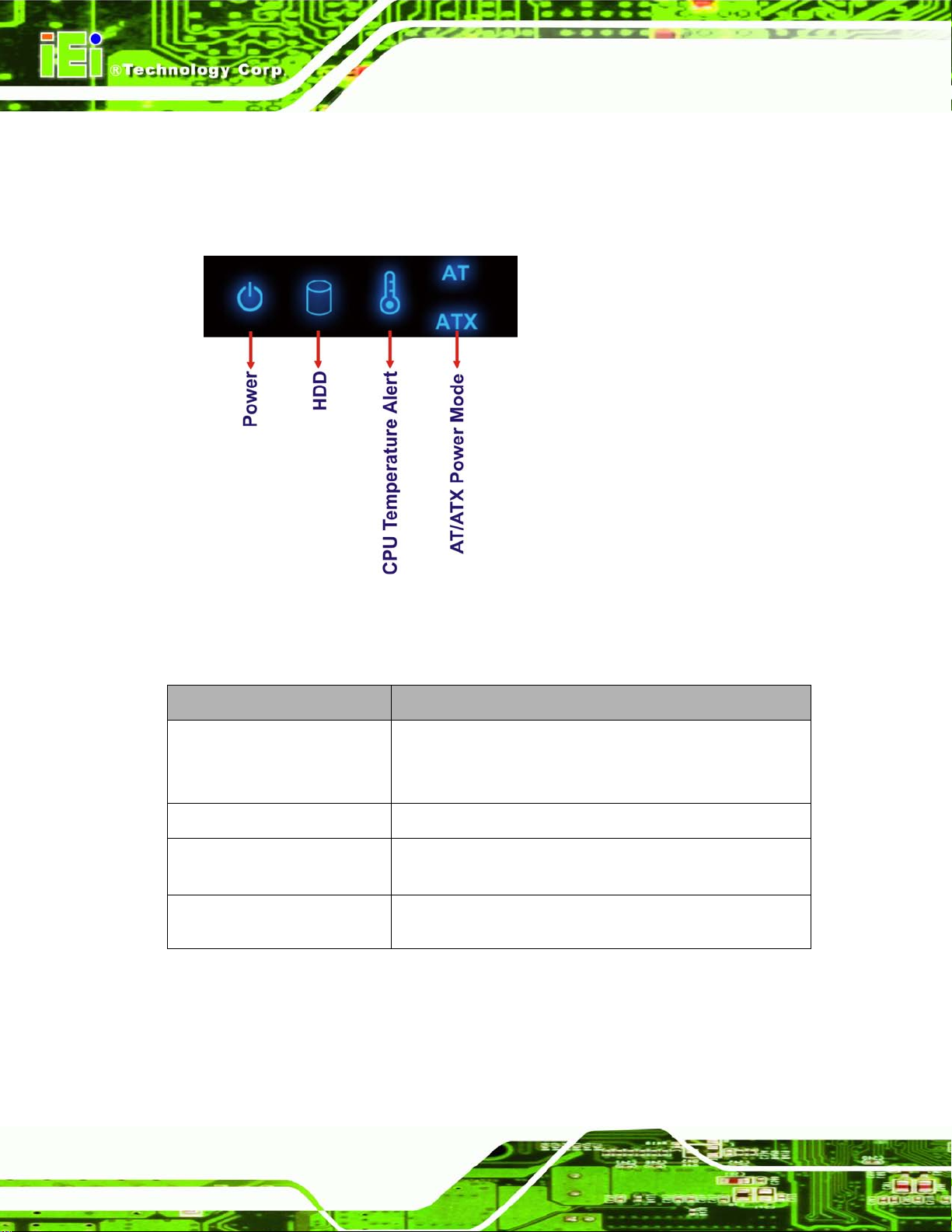
1.5.1 LED Indic ators
There are five LED in dicator lights located along the front panel of the ECN-680A-H61
(Figure 1-3).
Figure 1-3: LED Indicators
The descriptions of each LED indicator are listed below.
LED Indicator Description
Power
HDD
CPU T emperature Alert
AT/ATX Mode
Table 1-3: LED Indicators
Shows power status.
Orange: Standby mode.
Blue: Power-on mode.
Shows HDD status.
Blue: CPU temperature is normal.
Red: CPU temperature is too high.
Shows the power mode status. Controlled by the AT/ATX
power mode switch.
Page 21

ECN-680A-H61 Embedded System
Page 7
NOTE:
If the CPU temperature alert LED shows in red, the user must lower the
environments tem perature or close some running app lications to cool
down the CPU.
1.6 Rear Panel
The rear panel of the ECN-680A-H61 has the following features (Figure 1-4):
1 x AT/ATX Switch
1 x DVI-D port
1 x DVI-I port
1 x HDMI port
1 x 9 V ~ 36 V power jack
1 x Reset button
2 x RJ-45 LAN connectors
2 x RS-232 (DB-9 connector)
1 x RS-232 (RJ-45 connector)
1 x RS-422/485 (DB-9 connector)
1 x Temperature sensor
4 x USB 2.0 connectors
Page 22

ECN-680A-H61 Embedded System
Page 8
Figure 1-4: ECN-680A-H61 Rear Panel
Page 23

ECN-680A-H61 Embedded System
Page 9
1.7 Dimensions
The physical dimensions are shown below:
Figure 1-5: Physical Dimensions (mm)
Page 24

ECN-680A-H61 Embedded System
Page 10
Chapter
2
2 Unpacking
Page 25

ECN-680A-H61 Embedded System
Page 11
2.1 Anti-s tatic Precautions
WARNING:
Failure to take ESD precautions during installation may result in
permanent damage to the ECN-680A-H61 and severe injury to the
user.
Electrostatic discharge (ESD) can cause serious damage to electronic components,
including the ECN-680A-H61. Dry climates are especially susceptible to ESD. It is
therefore critical th at whenever the ECN-680A-H61 or any other e lectrical component is
handled, the following anti-static precautions are strictly adhered to.
Wear an anti-static wristband: Wearing a simple anti-static wristband can
help to prevent ESD from damaging the board.
Self-grounding: Before handling the board, touch any grounded conducting
material. During the time the board is handled, frequently touch any
conducting materials that are connected to the ground.
Use an anti-static pad: When configuring the ECN-680A-H61, place it on an
antic-static pad. This reduces the possibility of ESD damaging the
ECN-680A-H61.
2.2 Unpacking Precautions
When the ECN-680A-H61 is unpacked, please do the follow ing:
Follow the anti-static precautions outlined in Section
Make sure the packing box is facing upwards so the ECN-680A-H61 does not
fall out of the box.
Make sure all the components shown in Section
333H2.1.
334H2.3 are present.
Page 26

ECN-680A-H61 Embedded System
Page 12
2.3 Unpacking Checklist
NOTE:
If some of the components listed in the checklist below are missing,
please do not proceed with the installation. Contact the IEI resel ler or
vendor you purchased th e ECN-680A-H61 from or contact an IEI sales
representative directl y. To contact an IEI sa les representative, pl ease
send an email to
The ECN-680A-H61 is shipped with the following components:
Quantity Item and Part Number Imag e
1 ECN-680A-H61 multimedia box
1 Power adapter
(P/N: 63040-010090-020-RS)
1 Power cord
(P/N: 32702-000401-100-RS)
1 Power cord convert cable
(P/N: 32000-089400-RS)
165Hsales@iei.com.tw.
2 Mounting brackets
(P/N: 41020-0343C2-00-RS)
8 Mounting bracket screws
(P/N: 44015-030041-RS)
 Loading...