

Page 1
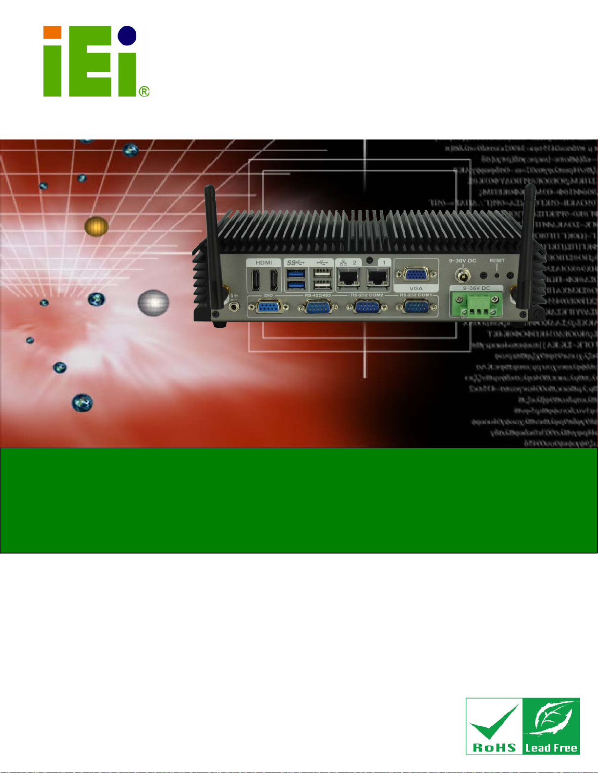
ECN-360A-HM65 Embedded System
Page i
MODEL:
Embedded System with Intel® Celeron® dual core 847E Proces sor,
Rev. 1.00 – 25 June 2013
,
IEI Technology Corp.
ECN-360A-HM65
Dual HDMI, VGA, GbE, Two USB 3.0, Two US B 2.0,
Three COM and RoHS Compliant
User Manual
Page 2
ECN-360A-HM65 Embedded System
Page ii
Date Version Changes
25 June 2013 1.00 Initial release
Revision
Page 3

ECN-360A-HM65 Embedded System
Page iii
Copyright
COP YRIGHT NOTICE
The information in this document is subject to change without prior notice in order to
improve reliabilit y, design a nd functi on and does not r epresent a com mitm ent on the par t
of the manufacturer.
In no event will the manufacturer be liable for direct, indirect, special, incidental, or
consequential damages arising out of the use or inability to use the product or
documentation, even if advised of the possibility of such damages.
This document contains proprietary information protected by copyright. All rights are
reserved. No part of this manual may be reproduced by any mechanical, e lectronic, or
other means in any form without prior written permission of the manufacturer.
TRADEMARKS
All registered tradem ark s and produc t nam es ment ioned here in are us ed for identif icatio n
purposes only and m ay be trademarks and/or registe red trademarks of their respecti ve
owners.
Page 4

ECN-360A-HM65 Embedded System
Page iv
Ta b le of Contents
1 INTRODUCTION .......................................................................................................... 1
1.1 OVERVIEW .................................................................................................................. 2
1.2 MODEL VARIATIONS ................................................................................................... 2
1.3 FEATURES ................................................................................................................... 2
1.4 TECHNICAL SPECIFICATIONS ...................................................................................... 3
1.5 FRONT PANEL ............................................................................................................. 4
1.6 REAR PANEL ............................................................................................................... 5
1.7 DIMENSIONS ............................................................................................................... 7
2 UNPACKING ................................................................................................................. 8
2.1 ANTI-STATIC PRECAUTIONS ........................................................................................ 9
2.2 UNPACKING PRECAUTIONS ......................................................................................... 9
2.3 UNPACKING CHECKLIST ........................................................................................... 10
3 INSTALLATION ......................................................................................................... 12
3.1 INSTALLATION PRECAUTIONS ................................................................................... 13
3.2 INST ALLATION AND CONFIGURATION STEPS ............................................................. 13
3.3 HARD DISK DRIVE (HDD) INSTALLATION ................................................................ 13
3.4 WI-FI ANTENNA INSTALLATION (WIRELESS MODEL ONLY) ..................................... 15
3.5 MOUNTING BRACKET INSTALLATION ....................................................................... 16
3.6 EXTERNAL PERIPHERAL INTERFACE CONNECTORS ................................................... 17
3.6.1 Audio Connection ............................................................................................. 17
3.6.2 HDMI Device Connection ................................................................................ 18
3.6.3 LAN Connection ............................................................................................... 19
3.6.4 DB-9 Serial Port Connection ........................................................................... 20
3.6.5 USB Device Connection ................................................................................... 21
3.6.6 VGA Monitor Connection ................................................................................ 22
4 SYSTEM MOTHERBOARD ..................................................................................... 24
4.1 PERIPHERAL INTERFACE CONNECTORS ..................................................................... 25
4.1.1 Layout .............................................................................................................. 25
Page 5

ECN-360A-HM65 Embedded System
Page v
4.1.2 Internal Peripheral Connectors ....................................................................... 26
4.1.3 External Interface Panel Connectors ............................................................... 27
4.2 INTERNAL PERIPHERAL CONNECTORS ...................................................................... 27
4.2.1 Audio Connector .............................................................................................. 27
4.2.2 Battery Connector ............................................................................................ 28
4.2.3 Digital Input/Output (DIO) Connector ............................................................ 29
4.2.4 Debug Connector ............................................................................................. 30
4.2.5 Fan Connector (CPU) ...................................................................................... 31
4.2.6 Fan Connector (System) .................................................................................. 31
4.2.7 Front Panel Connector .................................................................................... 32
4.2.8 LVDS Backlight Inverter Connector ................................................................ 33
4.2.9 Keyboard/Mouse Connector ............................................................................ 34
4.2.10 LVDS LCD Connector ................................................................................... 35
4.2.11 PCIe Mini Card Slot ....................................................................................... 36
4.2.12 Power Connector ........................................................................................... 38
4.2.13 SATA 6Gb/s Connector ................................................................................... 39
4.2.14 SATA Power Connectors ................................................................................ 40
4.2.15 Serial Port Connectors (COM 1 and COM 2) ............................................... 40
4.2.16 Serial Port Connector (COM3) ..................................................................... 41
4.2.17 SMBus Connector .......................................................................................... 42
4.2.18 SPI Flash Connector ...................................................................................... 43
4.3 EXTERNAL PERIPHERAL INTERFACE CONNECTOR PANEL ......................................... 44
4.3.1 Ethernet Connectors ........................................................................................ 45
4.3.2 HDMI Connectors ............................................................................................ 46
4.3.3 USB 2.0 Connectors ......................................................................................... 46
4.3.4 USB 3.0 Connectors ......................................................................................... 47
4.3.5 VGA Connector ................................................................................................ 48
4.4 JUMPER SETTINGS .................................................................................................... 49
4.4.1 AT/ATX Power Mode Select Jumper ................................................................ 49
4.4.2 Clear CMOS Jumper ........................................................................................ 50
4.4.3 LVDS Voltage Selection Jumper ....................................................................... 51
4.4.4 LVDS Panel Resolution Selection Jumper ....................................................... 52
4.4.5 TPM Setting Jumper ......................................................................................... 53
4.4.6 Flash Descriptor Security Override Jumper .................................................... 54
Page 6

ECN-360A-HM65 Embedded System
Page vi
5 BIOS .............................................................................................................................. 55
5.1 INTRODUCTION ......................................................................................................... 56
5.1.1 Starting Setup ................................................................................................... 56
5.1.2 Using Setup ...................................................................................................... 56
5.1.3 Getting Help ..................................................................................................... 57
5.1.4 Unable to Reboot After Configuration Changes .............................................. 57
5.1.5 BIOS Menu Bar ................................................................................................ 57
5.2 MAIN ........................................................................................................................ 58
5.3 ADVANCED ............................................................................................................... 59
5.3.1 ACPI Settings ................................................................................................... 59
5.3.2 RTC Wake Settings ........................................................................................... 60
5.3.3 CPU Configuration .......................................................................................... 62
5.3.4 SATA Configuration ......................................................................................... 63
5.3.5 USB Configuration ........................................................................................... 64
5.3.6 Super IO Configuration ................................................................................... 65
5.3.6.1 Serial Port n Configuration ....................................................................... 65
5.3.7 H/W Monitor .................................................................................................... 68
5.3.7.1 Smart Fan Mode Configuration ................................................................ 69
5.3.8 Serial Port Console Redirection ...................................................................... 70
5.3.8.1 Console Redirection Settings .................................................................... 71
5.4 IEI FEATURE ............................................................................................................. 74
5.5 CHIPSET ................................................................................................................... 74
5.5.1 NorthBridge Configuration .............................................................................. 76
5.5.1.1 Graphics Configuration ............................................................................. 77
5.5.2 Southbridge Configuration .............................................................................. 79
5.6 BOOT ........................................................................................................................ 81
5.7 SECURITY ................................................................................................................. 83
5.8 EXIT ......................................................................................................................... 84
A SAFETY PRECAUTIONS ......................................................................................... 86
A.1 SAFETY PRECAUTIONS ............................................................................................ 87
A.1.1 General Safety Precautions ............................................................................. 87
A.1.2 Anti-static Precautions .................................................................................... 88
A.1.3 Product Disposal ............................................................................................. 89
A.2 MAINTENANCE AND CLEANING PRECAUTIONS ........................................................ 89
Page 7

ECN-360A-HM65 Embedded System
Page vii
A.2.1 Maintenance and Cleaning .............................................................................. 89
A.2.2 Cleaning T ools ................................................................................................. 90
B BIOS MENU OPTIONS ............................................................................................. 91
C ONE KEY RECOVERY ............................................................................................. 94
C.1 ONE KEY RECOVERY INTRODUCTION ...................................................................... 95
C.1.1 System Requirement ........................................................................................ 96
C.1.2 Supported Operating System ........................................................................... 97
C.2 SETUP PROCEDURE FOR WINDOWS .......................................................................... 98
C.2.1 Hardware and BIOS Setup .............................................................................. 99
C.2.2 Create Partitions ............................................................................................. 99
C.2.3 Install Operating System, Drivers and Applications ..................................... 103
C.2.4 Building the Recovery Partition .................................................................... 104
C.2.5 Create Factory Default Image ...................................................................... 106
C.3 AUTO RECOVERY SETUP PROCEDURE ..................................................................... 111
C.4 SETUP PROCEDURE FOR LINUX ............................................................................... 115
C.5 RECOVERY TOOL FUNCTIONS ................................................................................. 119
C.5.1 Factory Restore ............................................................................................. 120
C.5.2 Backup System ............................................................................................... 121
C.5.3 Restore Your Last Backup .............................................................................. 122
C.5.4 Manual .......................................................................................................... 123
C.6 RESTORE SYSTEMS FROM A LINUX SERVER THROUGH LAN .................................. 124
C.6.1 Configure DHCP Server Settings .................................................................. 125
C.6.2 Configure TFTP Settings ............................................................................... 126
C.6.3 Configure One Key Recovery Server Settings ............................................... 127
C.6.4 Start the DHCP, TFTP and HTTP ................................................................. 128
C.6.5 Create Shared Directory ................................................................................ 128
C.6.6 Setup a Client System for Auto Recovery ...................................................... 129
C.7 OTHER INFORMATION ............................................................................................ 132
C.7.1 Using AHCI Mode or ALi M5283 / VIA VT6421A Controller ...................... 132
C.7.2 System Memory Requirement ........................................................................ 134
D WATCHDOG TIMER .............................................................................................. 135
E HAZARDOUS MATERIALS DISCLOSURE ....................................................... 138
E.1 HAZARDOUS MATERIALS DISCLOSURE TABLE FOR IPB PRODUCTS CERTIFIED AS
Page 8

ECN-360A-HM65 Embedded System
Page viii
ROHS COMPLIANT UNDER 2002/95/EC WITHOUT MERCURY ..................................... 139
Page 9

ECN-360A-HM65 Embedded System
Page ix
List of Figures
Figure 1-1: ECN-360A-HM65 .......................................................................................................... 2
Figure 1-2: ECN-360A-HM65 Front Panel
Figure 1-3: ECN-360A-HM65 Rear Pan el
Figure 1-4: Physical Dimensions (mm)
Figure 3-1: Retention Screws Removal
Figure 3-2: HDD Bracket
Figure 3-3: HDD Retention Screws
Figure 3-4: Wi-Fi Antenna Installation
Figure 3-5: Mounting Bracket Retention Screws
Figure 3-6: Audio Connector
Figure 3-7: HDMI Connection
Figure 3-8: LAN Connection
Figure 3-9: DB-9 Serial Port Connector
Figure 3-10: USB Device Connection
Figure 3-11: VGA Connector
Figure 4-1: Connectors and Jumpers Locations
Figure 4-2: Audio Connector Location
Figure 4-3: Battery Connector Location
..................................................................................... 5
...................................................................................... 6
........................................................................................ 7
......................................................................................14
..............................................................................................................14
.............................................................................................15
........................................................................................16
......................................................................16
.......................................................................................................18
......................................................................................................19
........................................................................................................20
......................................................................................21
.........................................................................................22
.......................................................................................................23
.......................................................................25
.......................................................................................28
.....................................................................................28
Figure 4-4: DIO Connector Location
Figure 4-5: EC Debug Connector Location
Figure 4-6: CPU Fan Connector Location
Figure 4-7: System Fan Connector Location
Figure 4-8: Front Panel Connector Location
Figure 4-9: Backlight Inverter Conn ecto r Location
Figure 4-10: Keyboard/Mouse Connector Location
Figure 4-11: LVDS Connector Location
Figure 4-12: PCIe Mini Card Slot Location
Figure 4-13: CPU Power Connector Location
Figure 4-14: SATA Drive Connector Loca tions
Figure 4-15: SATA Power Connector Locations
...........................................................................................29
................................................................................30
..................................................................................31
.............................................................................32
.............................................................................33
...................................................................34
..................................................................35
......................................................................................36
.................................................................................37
............................................................................38
.........................................................................39
.......................................................................40
Page 10

ECN-360A-HM65 Embedded System
Page x
Figure 4-16: COM Connector Locations .....................................................................................41
Figure 4-17: Serial Port Connector Loca tion
Figure 4-18: SMBus Connector Locatio n
Figure 4-19: SPI Flash Connector Location
Figure 4-20: External Peripheral Interface Connectors
Figure 4-21: RJ-45 Ethernet Connector
Figure 4-22: HDMI Connector
Figure 4-23: VGA Connector
Figure 4-24: AT/ATX Power Mode Jumper Location
Figure 4-25: Clear CMOS Jumper
Figure 4-26: LVDS Voltage Selection Jumper L oca tion
Figure 4-27: LVDS Screen Resolution Jumper Locations
Figure 4-28: TPM Setting Jumper Location
Figure 4-29: Flash Descriptor Security Override Jumper Location
Figure C-1: IEI One Key Recovery Tool Menu
Figure C-2: Launching the Recovery Tool
Figure C-3: Recovery Tool Setup Menu
Figure C-4: Command Prompt
.............................................................................42
...................................................................................43
...............................................................................44
............................................................44
......................................................................................45
......................................................................................................46
.......................................................................................................48
.................................................................50
...............................................................................................51
...........................................................52
........................................................53
...............................................................................54
........................................54
...........................................................................95
...............................................................................100
...................................................................................100
..................................................................................................101
Figure C-5: Partition Creation Commands
Figure C-6: Launching the Recovery Tool
Figure C-7: Manual Recovery Environment fo r Windows
Figure C-8: Building the Recovery Partition
Figure C-9: Press Any Key to Continue
Figure C-10: Press F3 to Boot into Recovery Mode
Figure C-11: Recovery Tool Menu ............................................................................................106
Figure C-12: About Symantec Ghost Window
Figure C-13: Symantec Ghost Path
Figure C-14: Select a Local Source Drive
Figure C-15: Select a Source Partition from Basic Drive
Figure C-16: File Name to Copy Image to
Figure C-17: Compress Image
Figure C-18: Image Creation Confirmation
Figure C-19: Image Creation Complete
Figure C-20: Image Creation Complete
Figure C-21: Press Any Key to Continue
...............................................................................102
...............................................................................104
......................................................104
............................................................................105
...................................................................................105
................................................................106
.........................................................................107
..........................................................................................107
................................................................................108
.......................................................108
................................................................................109
...................................................................................................109
..............................................................................110
....................................................................................110
....................................................................................110
.................................................................................111
Page 11

ECN-360A-HM65 Embedded System
Page xi
Figure C-22: Auto Recovery Utility ...........................................................................................112
Figure C-23: Launching the Recovery Tool
Figure C-24: Auto Recovery Environment for Windows
Figure C-25: Building the Auto Recovery Partition
Figure C-26: Factory Default Image Confirmation
Figure C-27: Image Creation Complete
Figure C-28: Press any key to continue
Figure C-29: Partitions for Linux
Figure C-30: Manual Recovery Environment for Linux
Figure C-31: Access menu.lst in Linux (Text Mode)
Figure C-32: Recovery Tool Menu
Figure C-33: Recovery Tool Main Menu
Figure C-34: Restore Factory Default
Figure C-35: Recovery Complete Window
Figure C-36: Backup System
Figure C-37: System Backup Complete Window
Figure C-38: Restore Backup
Figure C-39: Restore System Backup Complete Window
.............................................................................112
........................................................112
.................................................................113
..................................................................113
....................................................................................114
...................................................................................114
...............................................................................................116
..........................................................117
...............................................................118
............................................................................................118
...................................................................................119
.......................................................................................120
...............................................................................121
.....................................................................................................121
....................................................................122
....................................................................................................122
......................................................123
Figure C-40: Symantec Ghost Window
....................................................................................123
Page 12

ECN-360A-HM65 Embedded System
Page xii
List of Tables
Table 1-1: Model Variations ........................................................................................................... 2
Table 1-2: Technical Specifications
Table 2-1: Package List Contents
Table 4-1: Peripheral Interface Connectors
Table 4-2: Rear Panel Connectors
Table 4-3: Audio Connector Pinouts
Table 4-4: Battery Connector Pinouts
Table 4-5: DIO Connector Connector Pinouts
Table 4-6: Debug Connector Pinouts
Table 4-7: CPU Fan Connector Pinouts
Table 4-8: System Fan Connector Pinouts
Table 4-9: Front Panel Connector Pinouts
Table 4-10: Backlight Inverter Connector Pinouts
Table 4-11: Keyboard/Mouse Connector Pinouts
Table 4-12: LVDS Connector Pinouts
Table 4-13: PCIe Mini Card Slot Pinouts
Table 4-14: CPU Power Connector Pinouts
Table 4-15: SATA Drive Connector Pinouts
.............................................................................................. 4
...............................................................................................11
...............................................................................26
..............................................................................................27
..........................................................................................28
........................................................................................29
...........................................................................29
.........................................................................................30
.....................................................................................31
................................................................................32
.................................................................................33
....................................................................34
.....................................................................35
.........................................................................................36
....................................................................................38
...............................................................................39
...............................................................................39
Table 4-16: SATA Power Connector Pinouts
Table 4-17: COM Connector Pinouts
Table 4-18: Serial Port Connector Pinouts
Table 4-19: DB-9 RS-422/485 Pinouts
Table 4-20: SMBus Connector Pinouts
Table 4-21: SPI Flash Connector
Table 4-22: LAN Pinouts
Table 4-23: RJ-45 Ethernet Connector LEDs
Table 4-24: HDMI Connector Pinouts
Table 4-25: USB 2.0 Port Pinouts
Table 4-26: USB 3.0 Port Pinouts
Table 4-27: VGA Connector Pinouts
.............................................................................40
..........................................................................................41
................................................................................42
.........................................................................................42
......................................................................................43
.................................................................................................44
..............................................................................................................45
.............................................................................45
.........................................................................................46
................................................................................................47
................................................................................................47
...........................................................................................48
Page 13

ECN-360A-HM65 Embedded System
Page xiii
Table 4-28: Jumpers .....................................................................................................................49
Table 4-29: AT/ATX Power Mode Jumper Settings
Table 4-30: Clear CMOS Jumper Settings
Table 4-31: LVDS Voltage Selection Jumper Settings
Table 4-32: LVDS Screen Resolution Jumper Settings
Table 4-33: TPM Setting Jumper Settings
Table 4-34: Flash Descriptor Security Override Jumper Settings
Table 5-1: BIOS Navigation Keys
...................................................................50
..................................................................................51
..............................................................52
............................................................53
..................................................................................53
...........................................54
................................................................................................57
Page 14

ECN-360A-HM65 Embedded System
Page 1
Chapter
1
1 Introduction
Page 15

ECN-360A-HM65 Embedded System
Page 2
1.1 Overview
Figure 1-1: ECN-360A-HM65
The ECN-360A-HM65 embedded s ystem is a fanless system with two HDMI ports and
one VGA port for dual disp lay. It is powered by Intel® Celeron® dual core 847 E 1.1GHz
processor and supports two 204-pin DDR3 SDR AM SO-DIMM modules up to 8 GB (4GB
memory preinstalled). The ECN-360A-HM65 supports a 2.5” SATA HDD with up to 6 Gb/s
data transfer rate. Three serial ports, two USB 3.0 ports and t wo USB 2.0 ports ensure
simplified connectivity to a variety of external peripheral devices.
1.2 Mode l Variations
The model variations of the ECN-360A-HM65 series are listed below.
Models Wireless
ECN-360A-HM65/4G-R10 N/A
ECN-360AW-HM65/4G-R10 802.11b/g/n
Table 1-1: Model Variations
1.3 Features
The ECN-360A-HM65 features are listed below:
On-board CPU: Intel Celeron® 847E dual core 1.1GHz
Rich video output solution: 2 x HDMI + 1 x VGA
Ruggedized embedded computer: support -10°C~60°C with air flow (SSD)
Page 16

ECN-360A-HM65 Embedded System
Page 3
1.4 Technical Specifications
The ECN-360A-HM65 technical specifications are listed in Table 1-1.
Chassis
Color
Dimens ion ( WxDxH)
System Fan
Chassis Construction
Motherboard
Motherboard model
CPU
Chipset
System Memory
Ethernet
Storage
Hard Drive
Black
255 x 130 x 63
Fanless
SECC
NANO-HM651-847E
Intel® Celeron® dual core 847E 1.1GHz
Intel® HM65
2 x 204-pin DDR3 SDRAM SO-DIMM (System Max : 8GB)
Pre-installed DDR3 4GB memory
2 x Realtek RTL8111E PCIe GbE controller
1 x 2.5'' SATA HDD Bay
I/O interfaces
USB
LAN
RS-232
RS-422/485
Digit al I/O
Display
Resolution
2 x USB 3.0
2 x USB 2.0
2 x RJ-45 LAN
2 x RS-232 (DB-9 connector)
1 x RS-422/485 (DB-9 connector)
1 x DB-9 ; 8 bit Digital I/O , 4 bit input / 4 bit output
1 x VGA
2 x HDMI
VGA: Up to 2048 x 1536 @ 75Hz
HDMI: Up to 1920 x 1200 @ 60Hz
Page 17

ECN-360A-HM65 Embedded System
Page 4
Aud io
Wireles s
Expansions
PCIe Mi n i
Power
Power Input
Power Consumption
Reliability
Mounting
Operating Temperature
1 x Line-out
1 x 802.11 b/g/n ( optional)
1 x Full size ( reserved for Wi-Fi )
9~36V DC ( IDD-936260A)
Power 1 : DC Jack
Power 2: Terminal block
12V@3.01A
(Intel® Celeron® single core 827E 1.4GHz with 4GB DDR3 memory)
Wall mount ; VESA 100
-10°C~55°C with air flow (SSD)
0°C~45°C with air flow (HDD)
Storage Temperature
Operating Shock
Operating Vibration
Weight (Net/Gross)
Safety / EMC
OS
Supported OS
Table 1-2: Technical Specifications
-20°C ~ 60°C
Half-sine wave shock 3G; 11ms; 3 shocks per axis
MIL-STD-810F 514.5C-1
2.2 kg / 3 kg
CE / FCC Class A
Microsoft® WES7E
Microsoft® Windows® XP Embedded
1.5 Front Panel
The front panel of the ECN-360A-HM65 has the following features (Figure 1-2):
1 x HDD LED
1 x Power button
Page 18

ECN-360A-HM65 Embedded System
Page 5
Figure 1-2: ECN-360A-HM65 Front Panel
1.6 Rear Panel
The rear panel of the ECN-360A-HM65 has the following features (Figure 1-3):
1 x DIO connector
1 x Line-out
2 x HDMI connectors
1 x 9 V ~ 36 V power jack
1 x Reset button
2 x RJ-45 LAN connectors
2 x RS-232 (DB-9 connector)
1 x RS-422/485 (DB-9 connector)
1 x 9 V ~ 36 V terminal block
2 x USB 3.0 connectors
2 x USB 2.0 connectors
1 x VGA connector
2 x WiFi antenna connectors
Page 19

ECN-360A-HM65 Embedded System
Page 6
Figure 1-3: ECN-360A-HM65 Rear Panel
Page 20

ECN-360A-HM65 Embedded System
Page 7
1.7 Dimensions
The physical dimensions are shown below:
Figure 1-4: Physical Dimensions (mm)
Page 21

ECN-360A-HM65 Embedded System
Page 8
Chapter
2
2 Unpacking
Page 22

ECN-360A-HM65 Embedded System
Page 9
2.1 Anti-static Precautions
WARNING:
Failure to take ESD precautions during installation may result in
permanent damage to the ECN-360A-HM65 and severe inj ury to the
user.
Electrostatic discharge (ESD) can cause serious damage to electronic components,
including the ECN-360A-HM65. Dry climates are especially susceptible to ESD. It is
therefore critical th at when ever the ECN-360A-HM65 or any other electrical component is
handled, the following anti-static precautions are strictly adhered to.
Wear an anti-static wristband: Wearing a simple anti-static wristband can
help to prevent ESD from damaging the board.
Self-grounding: Before handling the board, touch any grounded conducting
material. During the time the board is handled, frequently touch any
conducting materials that are connected to the ground.
Use an anti-static pad: When configuring the ECN-360A-HM65, place it on
an antic-static pad. This reduces the possibility of ESD damaging the
ECN-360A-HM65.
2.2 Unpacking Precautions
When the ECN-360A-HM65 is unpacked, please do the following:
Follow the anti-static precautions outlined in Section 2.1.
Make sure the packing box is facing upwards so the ECN-360A-HM65 does
not fall out of the box.
Make sure all the components shown in Section 2.3 are present.
Page 23

ECN-360A-HM65 Embedded System
Page 10
2.3 Unpacking Checklist
NOTE:
If some of the components listed in the checklist below are missing,
please do not proceed with the installation. Contact the IEI resel ler or
vendor you purchased the ECN-360A-HM65 from or contact an IEI
sales representative directly. To contact an IEI sales representative,
please send an email to
The ECN-360A-HM65 is shipped with the following components:
Quantity Item and Part Number Image
1 ECN-360A-HM65
1 power adapter
1 power cord
2 Mounting brackets
sales@iei.com.tw.
1 Screw set
2 wireless antenna (for wireless model)
 Loading...