

Page 1
IEI Technology Corp.
User Manual
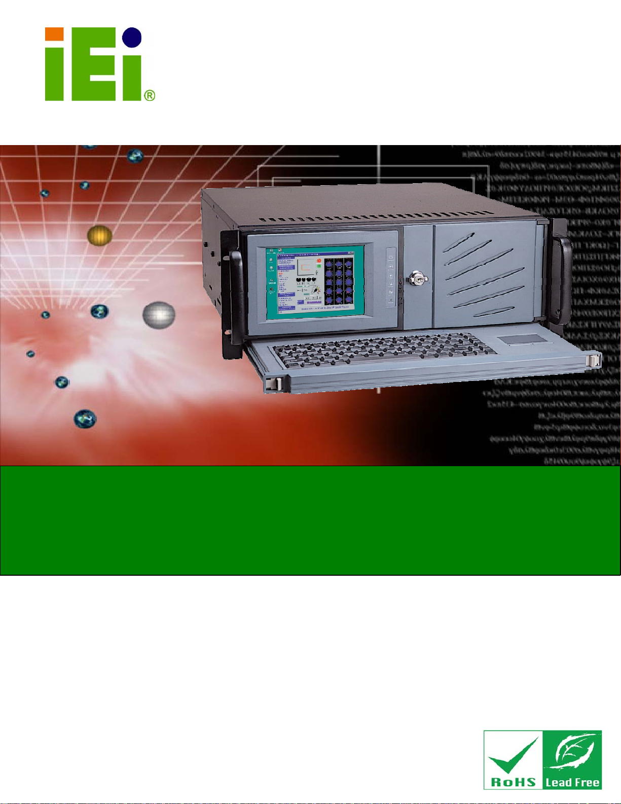
EC-1040GB Rackmount Workstation
MODEL:
EC-1040GB
4U 14-slot Rackmount LCD Workstation
Rev. 3.00 – 18 July, 2011
Page i
Page 2
Date Version Changes
18 July, 2011 3.00 Updated for R30 version
December, 2006 1.00 Initial release
EC-1040GB Rackmount Workstation
Revision
Page ii
Page 3
EC-1040GB Rackmount Workstation
COPYRIGHT NOTICE
The information in this document is subject to change without prior notice in order to
improve reliability, design and function and does not represent a commitment on the part
of the manufacturer.
In no event will the manufacturer be liable for direct, indirect, special, incidental, or
consequential damages arising out of the use or inability to use the product or
documentation, even if advised of the possibility of such damages.
This document contains proprietary information protected by copyright. All rights are
Copyright
reserved. No part of this manual may be reproduced by any mechanical, electronic, or
other means in any form without prior written permission of the manufacturer.
TRADEMARKS
All registered trademarks and product names mentioned herein are used for identification
purposes only and may be trademarks and/or registered trademarks of their respective
owners.
Page iii
Page 4
EC-1040GB Rackmount Workstation
Packing List
NOTE:
If any of the components listed in the checklist below are missing,
please do not proceed with the installation. Contact the IEI reseller or
vendor you purchased the EC-104G Rackmount Workstation from or
contact an IEI sales representative directly. To contact an IEI sales
representative, please send an email to
The items listed below should all be included in the EC-104G Rackmount Workstation
package.
1 x EC-104G Rackmount Workstatio n
1 x Screw Kit
1 x Power Cable
2 x PS/2 Cable
1 x VGA Cable
1 x RS-232 Cable
2 x Handle Bracket
2 x Handle
1 x Floppy Disk
1 x User Manual - CDROM
1 x PS/2 Cable (ATX model only)
sales@iei.com.tw.
Page iv
1 x RS-232 Cable (ATX model only)
1 x Touch Screen Touch Pen / Driver CDROM (ATX model only)
Images of the above items are shown in Chapter 3.
Page 5

EC-1040GB Rackmount Workstation
Table of Contents
1 INTRODUCTION...........................................................................................................1
1.1 EC-1040GB OVERVIEW.............................................................................................2
1.2 EC-1040GB FEATURES.............................................................................................. 2
1.3 MODEL VARIATIONS ................................................................................................... 2
1.4 OPTIONAL KEYBOARD ............................................................................................... 3
1.5 CERTIFICATIONS......................................................................................................... 4
2 MECHANICAL OVERVIEW......................................................................................... 5
2.1 EXTERNAL OVERVIEW................................................................................................ 6
2.1.1 Front Panel........................................................................................................ 6
2.1.2 14 Slot Rear Panel............................................................................................. 7
2.1.3 Motherboard Rear Panel................................................................................... 8
2.1.4 Top Panel ........................................................................................................... 9
2.1.5 Left Side Panel................................................................................................. 10
2.2 PHYSICAL DIMENSIONS............................................................................................ 10
2.2.1 General Physical Dimensions.......................................................................... 10
2.2.2 EC-1040GB Physical Dimensions....................................................................11
2.2.3 Optional Keyboard........................................................................................... 12
3 DETAILED SPECIFICATIONS.................................................................................. 13
3.1 EC-1040GB SPECIFICATIONS................................................................................... 14
3.2 LCD SPECIFICATIONS............................................................................................... 15
3.3 ACE-832AP PSU SPECIFICATIONS .......................................................................... 16
3.4 RECOMMENDED IEI BACKPLANES, MOTHERBOARDS AND PSUS ............................. 17
4 INSTALLATION........................................................................................................... 18
4.1 INSTALLATION CONSIDERATIONS.............................................................................. 19
4.1.1 Installation Precautions................................................................................... 19
4.1.2 Installation Prerequisites................................................................................. 19
4.2 UNPACKING.............................................................................................................. 20
4.2.1 Packaging ........................................................................................................ 20
Page v
Page 6

4.2.2 Unpacking Procedure ...................................................................................... 20
4.2.3 Packing List ..................................................................................................... 21
4.3 PRE-INSTALLATION PREPARATION ............................................................................ 23
4.3.1 System Planning............................................................................................... 23
4.3.2 Tools................................................................................................................. 23
4.4 INSTALLATION PROCEDURES .................................................................................... 24
4.4.1 Preinstalled Components................................................................................. 24
4.4.2 User Installed Components.............................................................................. 24
4.4.3 Installation Steps.............................................................................................. 24
4.5 INSTALLING COMPONENTS INTO THE EC-1040GB................................................... 25
4.5.1 Remove the Top Cover ..................................................................................... 25
4.5.2 Remove the CPU Card Clamp......................................................................... 27
4.5.3 Remove the Drive Bracket ............................................................................... 27
4.5.4 Remove the Drive Slot Blank Plate.................................................................. 28
EC-1040GB Rackmount Workstation
4.5.5 Remove the 3.5” Drive Bracket....................................................................... 29
4.5.6 Install Drives.................................................................................................... 30
4.5.6.1 5.25” Disk Drive....................................................................................... 30
4.5.6.2 3.5” Disk Drive in a 5.25” Slot................................................................. 31
4.5.6.3 3.5” Disk Drive......................................................................................... 32
4.5.7 Reinstall the Drive Brackets ............................................................................ 33
4.5.8 Install the Backplane........................................................................................ 33
4.5.9 Install the CPU Card....................................................................................... 36
4.5.10 Install the PCI/ISA Expansion Card.............................................................. 38
4.5.11 Connect the Cables......................................................................................... 39
4.5.12 Close the Top Cover....................................................................................... 39
4.5.13 Install Optional Keyboard ............................................................................. 40
4.6 MOUNTING THE EC-1040GB RACKMOUNT WORKSTATION ..................................... 41
5 MAINTENANCE.......................................................................................................... 48
5.1 MAINTENANCE OVERVIEW....................................................................................... 49
5.2 CPU CARD REPLACEMENT ...................................................................................... 50
5.3 PCI/ISA EXPANSION CARD REPLACEMENT.............................................................. 50
5.4 BACKPLANE REPLACEMENT..................................................................................... 51
5.5 PSU REPLACEMENT................................................................................................. 52
5.6 COOLING FAN REPLACEMENT .................................................................................. 55
Page vi
Page 7

EC-1040GB Rackmount Workstation
5.7 DISK DRIVE REPLACEMENT ..................................................................................... 57
5.7.1 3.5” Disk Drive Replacement.......................................................................... 57
5.7.2 5.25” Disk Drive Replacement........................................................................ 58
6 ON SCREEN DISPLAY (OSD) CONTROLS.............................................................. 59
6.1 USER MODE OSD STRUCTURE................................................................................. 60
6.1.1 OSD Buttons..................................................................................................... 60
6.1.2 OSD Menu Structure........................................................................................ 61
6.1.3 Main Menu....................................................................................................... 62
6.1.4 Color Menu...................................................................................................... 62
6.1.5 Image Setting Menu ......................................................................................... 64
6.1.6 Position Menu.................................................................................................. 65
6.1.7 OSD Menu........................................................................................................ 66
6.1.8 Language Menu ............................................................................................... 67
6.1.9 Misc. Menu....................................................................................................... 68
7 A106 UTILITY .............................................................................................................. 69
7.1 A106 UTILITY OVERVIEW........................................................................................ 70
A CERTIFICATIONS...................................................................................................... 71
A.1 ROHS COMPLIANT.................................................................................................. 72
B RECOMMENDED IEI BACKPLANES, MOTHERBOARDS AND PSUS.............. 73
B.1 RECOMMENDED IEI BACKPLANES AND MOTHERBOARDS ....................................... 74
B.2 RECOMMENDED IEI POWER SUPPLY UNITS ............................................................. 74
Page vii
Page 8

EC-1040GB Rackmount Workstation
List of Figures
Figure 2-1: EC-1040GB Front Panel..............................................................................................6
Figure 2-2: EC-1040GB 14 Slot Rear Panel..................................................................................7
Figure 2-3: EC-1040GB Motherboard Rear Panel........................................................................8
Figure 2-4: EC-1040GB Top Panel ................................................................................................9
Figure 2-5: EC-1040GB Left Side Panel......................................................................................10
Figure 2-6: EC-1040GB Physical Dimensions (millimeters).....................................................11
Figure 2-7: Optional Keyboard....................................................................................................12
Figure 4-1: Top Cover Left Side Retention Screws (Right Side Similar) ................................26
Figure 4-2: Remove Top Cover from Chassis ...........................................................................26
Figure 4-3: CPU Card Clamp Retention Screws........................................................................27
Figure 4-4: Drive Bracket Retention Screws..............................................................................28
Figure 4-5: Drive Slot Blank Plate Retention Screws................................................................29
Figure 4-6: 3.5” Drive Bracket Retention Screws......................................................................30
Figure 4-7: 5.25” Disk Drive Retention Screws (Other Side Similar).......................................31
Figure 4-8: 3.5” to 5.25” Drive Bay Rack Retention Screws ....................................................32
Figure 4-9: 3.5” Disk Drive Retention Screws ...........................................................................33
Figure 4-10: Install Copper Pillars ..............................................................................................34
Figure 4-11: Backplane Retention Screws.................................................................................35
Figure 4-12: Slot Cover Retention Screw...................................................................................37
Figure 4-13: Install the CPU Card................................................................................................38
Figure 4-14: Internal PS/2 Connector .........................................................................................40
Figure 4-15: Keyboard Retention Screws ..................................................................................41
Figure 4-16: Rack Handle Bracket Assembly and Installation.................................................42
Figure 4-17: Remove Rack Slide.................................................................................................43
Figure 4-18: Workstation Slide Installation (Other Side Similar).............................................44
Figure 4-19: Rack Slide Bracket Assembly................................................................................45
Figure 4-20: Rack Slide Bracket Installation..............................................................................46
Figure 4-21: Install Workstation into Rack.................................................................................47
Figure 5-1: PSU External Retention Screws..............................................................................52
Figure 5-2: PSU Internal Retention Screws ...............................................................................53
Page viii
Page 9

EC-1040GB Rackmount Workstation
Figure 5-3: PSU Mounting Bracket Retention Screws..............................................................54
Figure 5-4: Cooling Fan Spring Clips.........................................................................................56
Figure 6-1: OSD Control Buttons................................................................................................60
Figure 6-2: Main Menu..................................................................................................................62
Figure 6-3: Color Menu ................................................................................................................63
Figure 6-4: Image Setting Menu..................................................................................................64
Figure 6-5: Image Menu ...............................................................................................................65
Figure 6-6: OSD Menu..................................................................................................................66
Figure 6-7: Language Menu.........................................................................................................67
Figure 6-8: Misc. Menu.................................................................................................................68
Figure 7-1: A106 Alarm Board Cabling.......................................................................................70
Page ix
Page 10

EC-1040GB Rackmount Workstation
List of Tables
Table 1-1: EC-1040GB Model Variations ......................................................................................3
Table 2-1: General Physical Dimensions ...................................................................................10
Table 3-1: EC-1040GB Specifications.........................................................................................14
Table 3-2: LCD Specifications.....................................................................................................15
Table 3-3: ACE-A130A-R10 PSU Specifications........................................................................16
Table 4-1: Packing List.................................................................................................................23
Table 6-1: OSD Menu Structure...................................................................................................62
Page x
Page 11
EC-1040GB Rackmount Workstation
Chapter
1
1 Introduction
Page 1
Page 12

1.1 EC-1040GB Overview
The EC-1040GB is a PC/AT compatible computer designed for industrial applications. It
has a rugged steel chassis specially designed to work under harsh environmental
conditions while also being high reliability. The EC-1040GB features 14-slot passive
backplanes and a full line of dependable AC/DC power supplies. The EC-1040GB can
withstand shock, vibration, dust and a wide range of temperatures in industrial
environments. A lockable door protects drive bays and switches from unauthorized
misuse and dust. The EC-1040GB also has two removable cooling-fans installed in the
front panel for optimum cooling of the system.
1.2 EC-1040GB Features
Some of the features of the EC-1040GB include:
6.5” TFT LCD with fully functional OSD
EC-1040GB Workstation
Multi-function thermal alarm system
Optional KM-088G (keyboard and touch pad module)
Optional Touch screen
Flexible driver combination
PICMG 1.3 backplane and Redundant power supply support
Advanced air-flow design
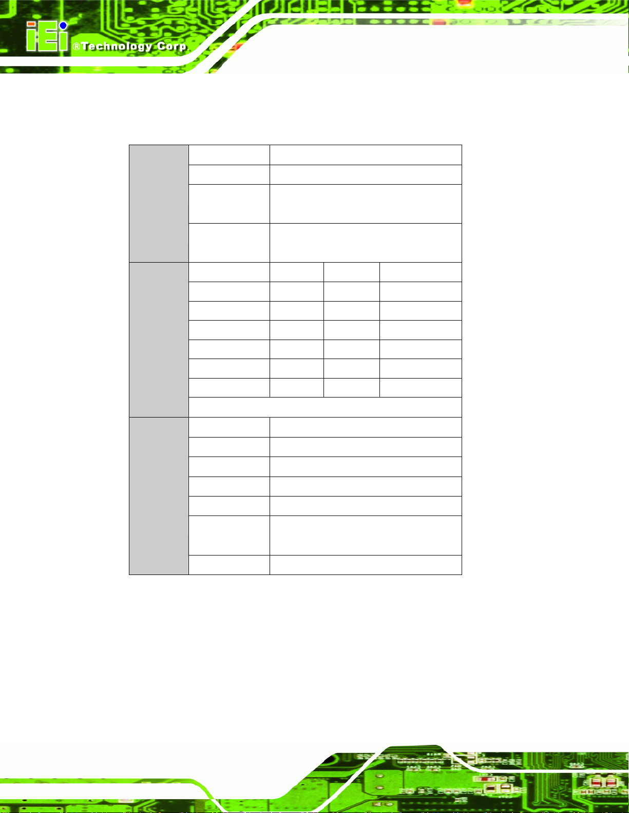
1.3 Model Variations
The EC-1040GB comes in a variety of models. The models have special features as
identified by their model name. The EC-1040GB model variations are listed in
Table 1-1.
Page 2
Page 13
EC-1040GB Workstation
EC-1040GBB/A130A-R30
EC-1040GBB/A130A/R-R30
EC-1040GBBATX/A130A-R30
EC-1040GBBATX/A130A/R-R30
Table 1-1: EC-1040GB Model Variations
1.4 Optional Keyboard
The KM-088G-(L) optional keyboard may be purchased separately for the EC-1040GB
rackmount workstation with the following specifications:
88 keys
Touch
Screen
No No Yes 14
Yes No Yes 14
No Yes Yes 7
Yes Yes Yes 7
ATX Motherboard
Rear Panel
300W
Expansion
Power
Slots
Supply
Touchpad with left and right buttons
Num lock, Caps lock and Scroll lock indicators
PS/2 keyboard connector
(L) specifies keyboard language
o DE: German
o EN: English
o FR: French
o IT: Italian
o JP: Japanese
o RU: Russian
o SP: Spanish
o TW: Traditional Chinese
Page 3
Page 14

1.5 Certifications
All EC-1040GB rackmount workstations comply with the following international standards:
RoHS
For a more detailed description of this standard, please refer to Appendix A.
EC-1040GB Workstation
Page 4
Page 15
EC-1040GB Workstation
Chapter
2
2 Mechanical Overview
Page 5
Page 16
2.1 External Overview
The following sections describe the physical layout of the EC-1040GB rackmount
workstation.
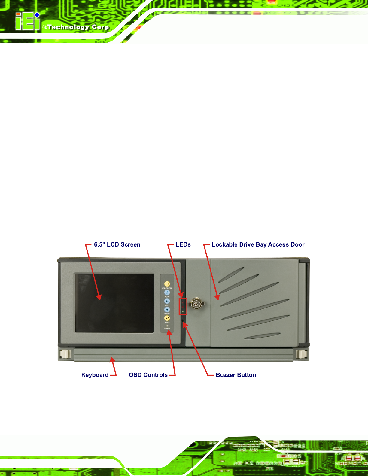
2.1.1 Front Panel
The EC-1040GB rackmount workstation has the following front panel items:
Plastic frame
6.5” Flat panel TFT LCD screen with OSD controls
Lockable drive bay access door conceals
o Three 5.25” drive bays
o One 3.5” drive bay
o Power switch
Temperature, LAN and fan LEDs
EC-1040GB Workstation
Buzzer off button
Optional Keyboard
Page 6
Figure 2-1: EC-1040GB Front Panel
Page 17
EC-1040GB Workstation
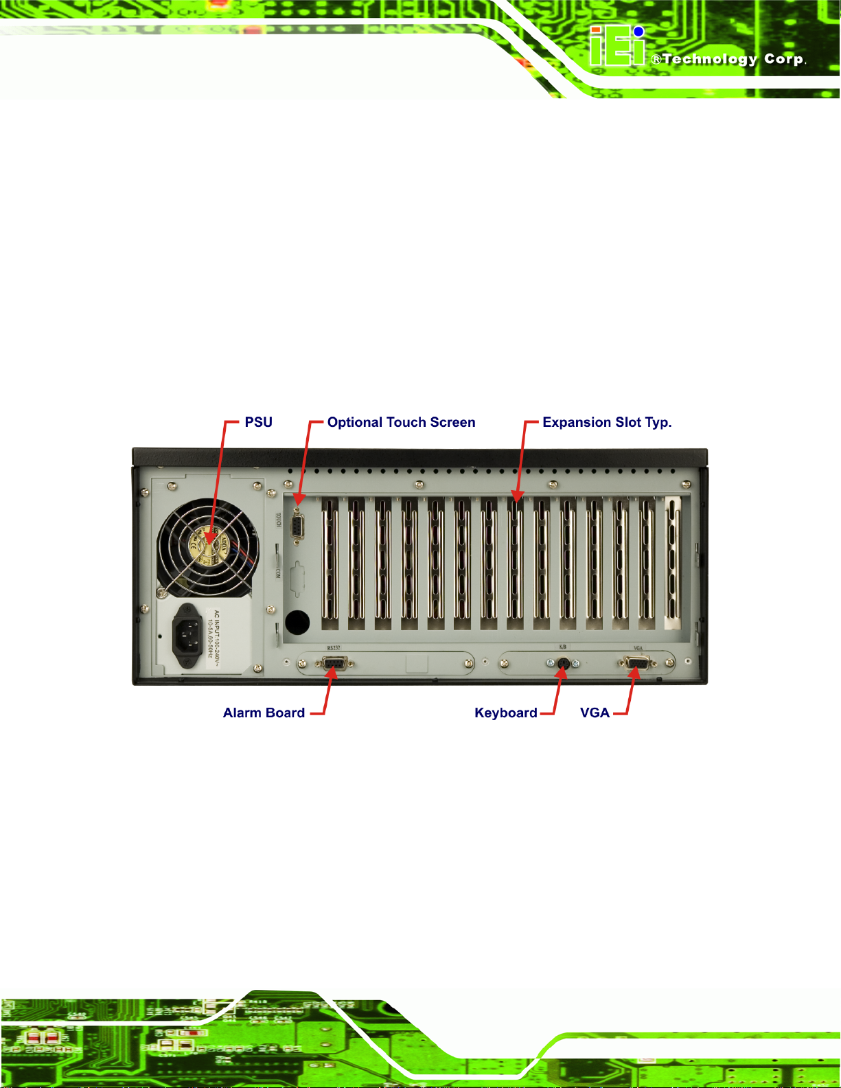
2.1.2 14 Slot Rear Panel
The EC-1040GB rackmount workstation has the following rear panel items:
Internal PSU
14 expansion slots
VGA connector
Keyboard connector
Serial connector for alarm board
Optional Touch Screen connector
Figure 2-2: EC-1040GB 14 Slot Rear Panel
Page 7
Page 18
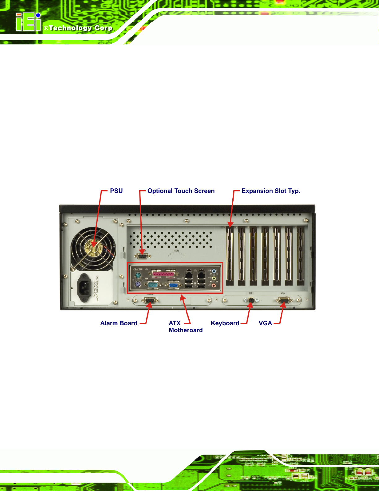
2.1.3 Motherboard Rear Panel
The EC-1040GB rackmount workstation also has an optional motherboard rear panel with
the following items:
Internal PSU
7 expansion slots
VGA connector
Keyboard connector
Serial connector for alarm board
Optional Touch Screen connector
ATX Motherboard connector area
EC-1040GB Workstation
Page 8
Figure 2-3: EC-1040GB Motherboard Rear Panel
Page 19
EC-1040GB Workstation
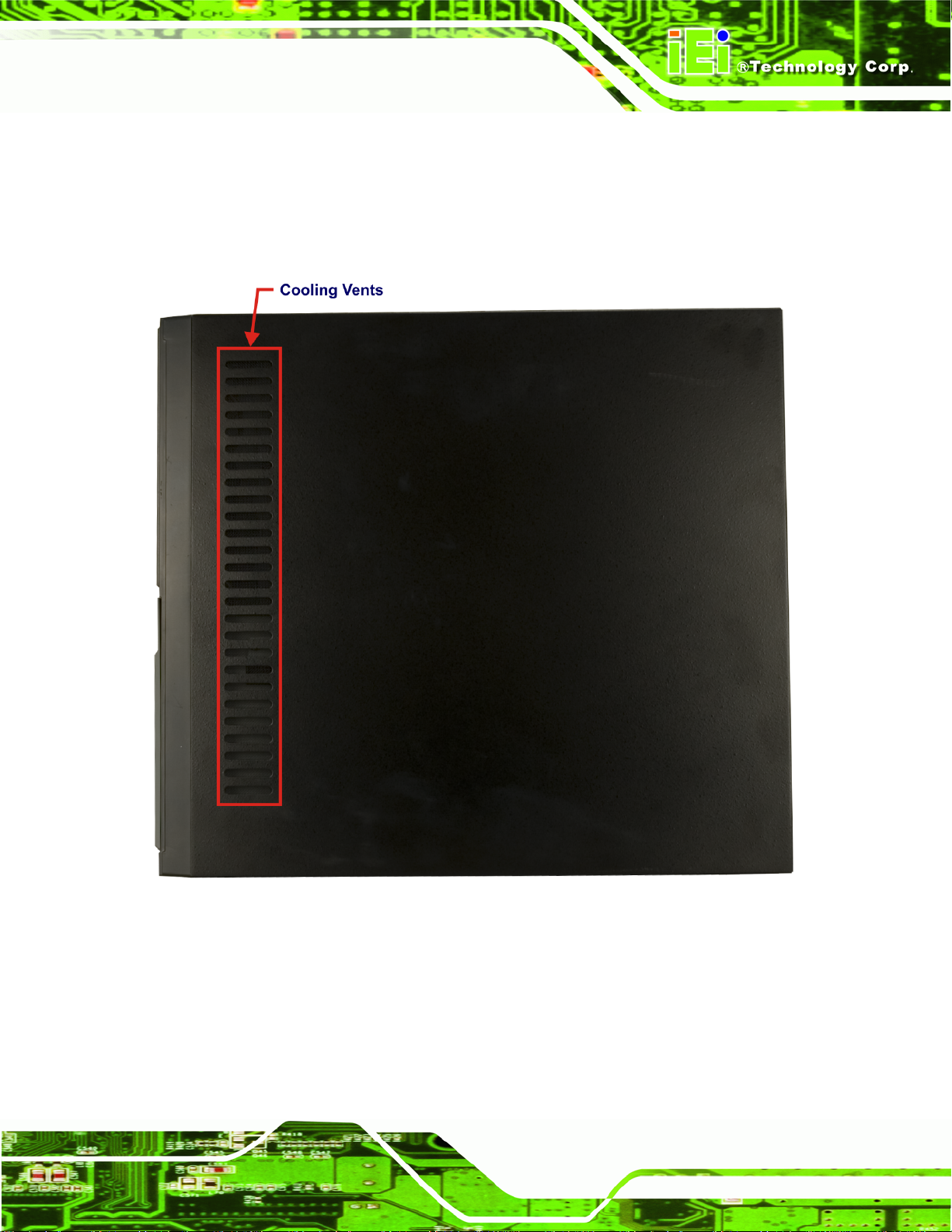
2.1.4 Top Panel
The EC-1040GB rackmount workstation has the following top panel items:
Cooling vents
Figure 2-4: EC-1040GB Top Panel
Page 9
Page 20
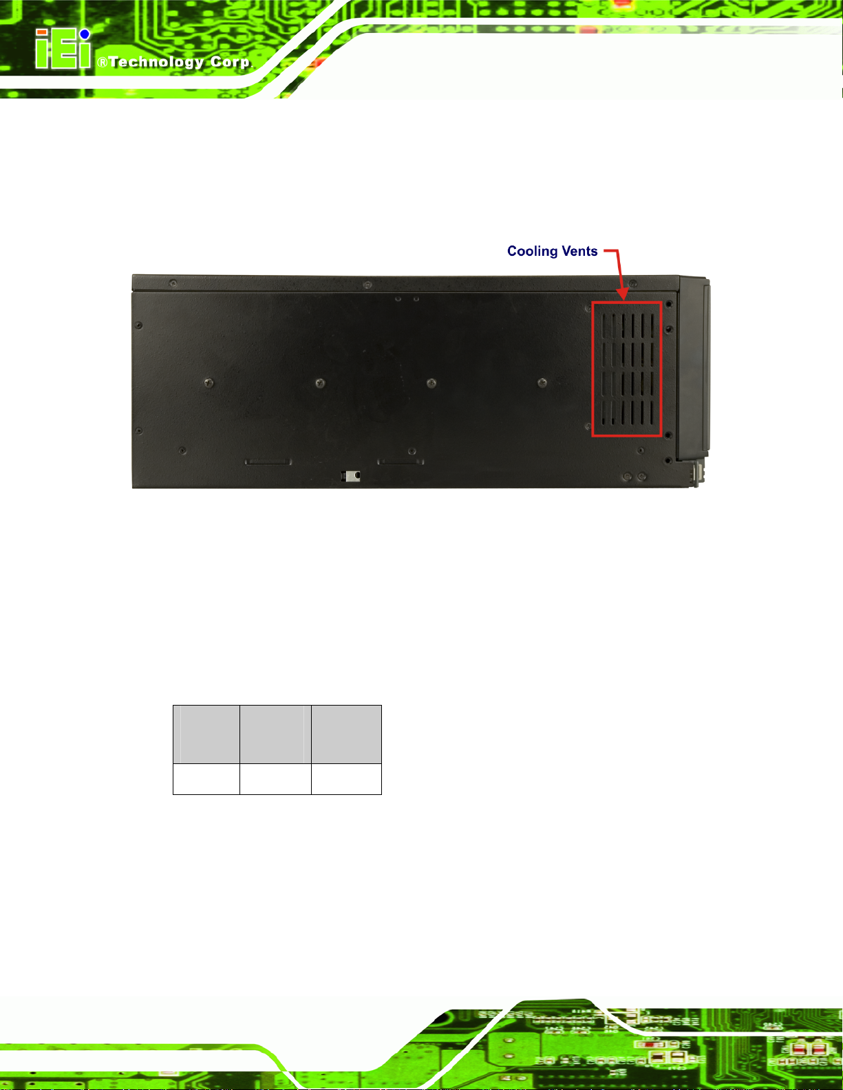
2.1.5 Left Side Panel
The EC-1040GB rackmount workstation has the following left side panel items:
Cooling vents
EC-1040GB Workstation
Figure 2-5: EC-1040GB Left Side Panel
2.2 Physical Dimensions
The following sections describe the physical dimensions of the EC-1040GB.
2.2.1 General Physical Dimensions
General physical dimensions for the EC-1040GB are shown in Table 2-1.
Width
(mm)
431 177 480
Table 2-1: General Physical Dimensions
Height
(mm)
Depth
(mm)
Page 10
Page 21
EC-1040GB Workstation
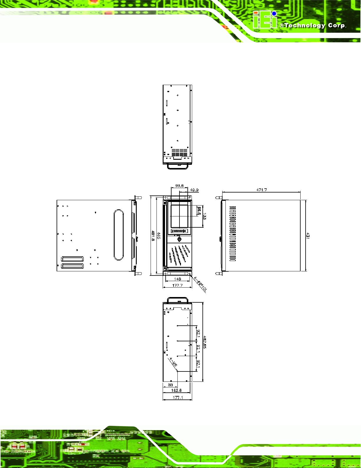
2.2.2 EC-1040GB Physical Dimensions
The physical dimensions of the EC-1040GB are shown in Figure 2-1.
Figure 2-6: EC-1040GB Physical Dimensions (millimeters)
Page 11
Page 22
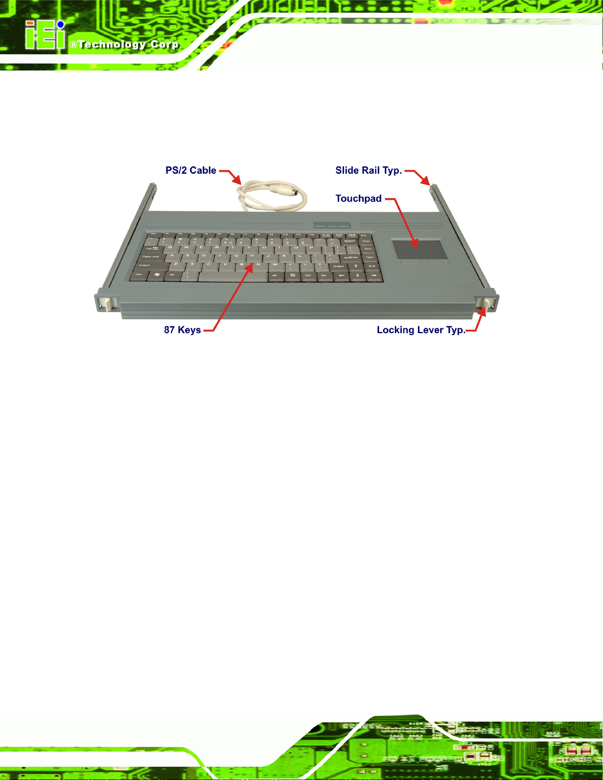
2.2.3 Optional Keyboard
Figure 2.7 shows the optional keyboard for the EC-1040GB rackmount workstation. Refer
to Section 4-5-13 for installation details.
EC-1040GB Workstation
Figure 2-7: Optional Keyboard
Page 12
Page 23

EC-1040GB Workstation
Chapter
3
3 Detailed Specifications
Page 13
Page 24
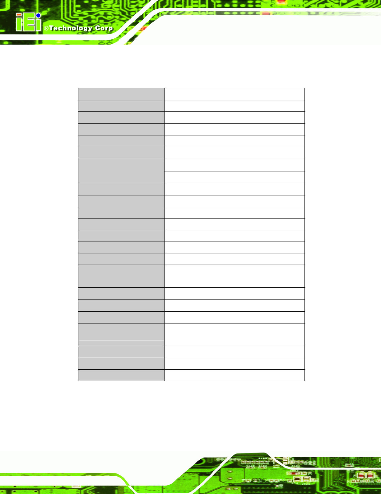
3.1 EC-1040GB Specifications
Table 3-1 shows the EC-1040GB specifications.
LCD Type 6.5" TFT
Input Interface VGA
Max. Resolution 640 x 480
Backlight MTBF 50,000 Hrs
Contrast 600:1
LCD Color 262K
Brightness (cd/m2) 800
Chassis Heavy-duty steel
EC-1040GB Workstation
View Angle (H / V)
OSD function Yes
Mounting 19” Rack Mount
Rack Height 4U
Keyboard 88 Keys – Slim Size (Keyboard models only)
Touch Pad Yes – with 2 buttons
Cooling Fan 2 – 8cm
Expansion Slots
Dimensions (WxHxD) (mm) 431 x 177 x 480
Weight (Gross/Net) 15.3kg / 28.8kg
Color Black (Pantone Black C)
Vibration
Shock 10G acceleration peak to peak (11ms)
Humidity 5 ~ 95%, relative
160° / 140°
14 for EC-1040GB
7 for EC-1040GBATX
5 ~ 17 Hz, 0.1” double amplitude displacement
17 ~ 640 Hz, 1.5G acceleration peak to peak
Operating Temperature 0 ~ 50°C
Table 3-1: EC-1040GB Specifications
Page 14
Page 25
EC-1040GB Workstation
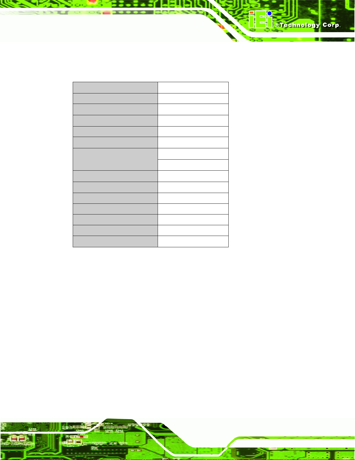
3.2 LCD Specifications
Table 3-2 lists the EC-1040GB LCD specifications.
Size 6.5”
MFR/Model AUO/G065VN01 V2
Resolution VGA (640 x 480)
Active Area (mm) 132.52 x 98.64
Pixel Pitch (mm) 0.207
Number of Colors 262K
View Angle (H/V)
Brightness (cd/m2) 800
Contrast Ratio 600:1
Response Time (ms) (at 25C) 25
Power Consumption (W) 3.86
Interface LVDS
Supply Voltage (V) 3.3
Backlight CCFL side light (L-type)
Lamp Life (hrs) 50000
Table 3-2: LCD Specifications
160° / 140°
Page 15
Page 26
3.3 ACE-832AP PSU Specifications
Table 3-3 lists the ACE-A130A-R10 power supply specifications.
INPUT Voltage 90 ~ 264 VAC Full Range
Frequency 47 ~ 63 Hz
Input Current 6A (RMS) @ 115 VAC
3A (RMS) @ 230 VAC
Inrush Current 60 A Max for 115 VAC
90 A Max for 230 VAC
OUTPUT Voltage Min. load Max. load Ripple & Noise
+3.3V 0.1 A 28 A 50 mV
+5V 0.2 A 30 A 50 mV
+12V1 0.1 A 15 A 120 mV
+12V2 0.5 A 0.3 A 120 mV
EC-1040GB Workstation
-12V 0 A 0.8 A 120 mV
+5Vsb 0 A 2 A 50 mV
Total Current of +3.3V & +5V & +12V ≦280W
GENERAL Power 300W
PFC Active
Hold-up Time 17ms minimum
Efficiency 65%
MTBF 100,000hrs
Temperature -5 ~ 50°C (Operating)
-20 ~ 80°C (Storage)
Dimensions 140 mm x 150 mm x 86 mm
Table 3-3: ACE-A130A-R10 PSU Specifications
Page 16
Page 27

EC-1040GB Workstation
3.4 Recommended IEI Backplanes, Motherboards and PSUs
Refer to Appendix B for recommended IEI backplanes, motherboards and power supply
units for the EC-1040GB rackmount workstation.
Page 17
Page 28

EC-1040GB Workstation
Chapter
4
4 Installation
Page 18
Page 29

EC-1040GB Workstation
4.1 Installation Considerations
4.1.1 Installation Precautions
When installing the EC-1040GB, please follow the precautions listed below:
Read the user manual: The user manual provides a complete description of
the EC-1040GB rackmount workstation, installation instructions and
configuration options.
Turn Off Power: When installing the EC-1040GB rackmount workstation,
make sure the power is off. Failing to turn off the power may cause severe
injury to the user and/or damage the system.
Certified Engineers: Only certified engineers and technicians should install
and modify the EC-1040GB rackmount workstation. Non-certified engineers
or technicians should not attempt to install the EC-1040GB rackmount
workstation.
Mounting: The EC-1040GB rackmount workstations are heavy devices.
When rack mounting the EC-1040GB rackmount workstation, please ensure
that at least two people are assisting with the procedure.
Anti-static Discharge: Electronic components like CPU cards and
backplanes must be installed into the EC-1040GB rackmount workstation.
Follow proper grounding procedures before installing these components.
4.1.2 Installation Prerequisites
Prepare the following before installing the EC-1040GB rackmount workstation:
Completely installed CPU card: The EC-1 040GB rackmount workstation
CPU card is separately purchased. Before installing the EC-1040GB
rackmount workstation, a CPU card should be properly installe d. The
following components may also have to be installed (refer to the user manual
that came with the CPU card):
o CPU
o Heatsink and cooling fan
o Memory modules (DIMMs)
o Compact flash disks
Backplane/Motherboard: The backplane or motherboard installed in the
Page 19
Page 30

EC-1040GB rackmount workstation is separately purchased.
Disk Drives: Disk drives installed into the EC-1040GB rackmount workstation
are separately purchased. Disk drive support is CPU card dependent. Before
purchasing a CPU card or disk drives, please check the CPU card disk drive
support.
4.2 Unpacking
4.2.1 Packaging
When shipped, the EC-1040GB rackmount workstation is wrapped in a plastic bag. Two
polystyrene ends are placed on either side of the EC-1040GB rackmount workstation. The
workstation is then placed into a first (internal) cardboard box. This box is then sealed and
placed into a second (external) cardboard box. The second box is also sealed. A small
box containing accessory items is placed within the internal (first) box.
EC-1040GB Workstation
4.2.2 Unpacking Procedure
To unpack the EC-1040GB rackmount workstation, follow the steps below:
NOTE:
The front side LCD screen has a protective plastic cover stuck to the screen.
Remove the plastic cover only after the EC-1040GB rackmount workstation has
been properly installed. This ensures the screen is protected during the
installation process.
Step 1: Use box cutters, a knife or a sharp pair of scissors to open the top of the external
(second) box.
Step 2: Open the external (second) box.
Page 20
Page 31

EC-1040GB Workstation
Step 3: Use box cutters, a knife or a sharp pair of sci ssors to o pen the top of the intern al
(first) box.
Step 4: Lift the workstation out of the boxes.
Step 5: Remove both polystyrene ends from each side.
Step 6: Pull the plastic cover off the workstation.
Step 7: Make sure all the components listed in the pa cking list are present.
Step 0:
4.2.3 Packing List
NOTE:
If some of the components listed in the checklist below are missing, please do
not proceed with the installation. Contact the IEI reseller or vendor you
purchased the AC-KIT-883HD audio module from or contact an IEI sales
representative directly. To contact an IEI sales representative, please send an
email to
When the EC-1040GB rackmount workstation is received, make sure all the components
listed below are present.
Quantity Description Image
sales@iei.com.tw.
2 Door key
2 Handle
Page 21
Page 32

Quantity Description Image
2 Handle bracket
EC-1040GB Workstation
1 Power cable
2 PS/2 Keyboard/Mouse cable
1 Screw kit
1 Utility CD
1 VGA cable
For Touch Panel (T-R) Models only
1 RS-232 cable
Page 22
Page 33
EC-1040GB Workstation
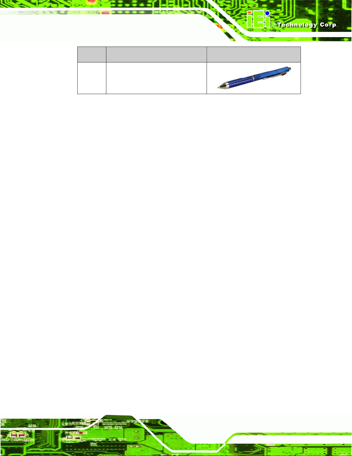
Quantity Description Image
1 Touch pen
Table 4-1: Packing List
4.3 Pre-installation Preparation
4.3.1 System Planning
User supplied CPU cards and backplanes or motherboards need to be installed in the
system before installing the EC-1040GB rackmount workstation.
The backplane determines the following system parameters:
CPU card type
Expandability
The CPU card determines the following system parameters:
CPU
Embedded graphics
System memory
HDD, FDD and optical drive connectivity and capacity
Speed
It is therefore proper to correctly specify the system before the system is installed. This
ensures that prudent selections can be made when the system is being developed.
4.3.2 Tools
Before installing the EC-1040GB rackmount workstation, make sure the following tools are
on hand:
Philips (crosshead) screwdriver: All the retention screws on the system are
Philips screws.
Soft working mat: When installing the EC-1040GB ra ckmount wo rkstation, the
Page 23
Page 34

screen should be placed face down on a soft wo rking mat.
4.4 Installation Procedures
4.4.1 Preinstalled Components
The following components are preinstalled in the EC-1040GB rackmount workstation.
Power supply unit (PSU)
Cooling fan modules
Drive brackets
LCD screen
4.4.2 User Installed Components
EC-1040GB Workstation
The following user supplied components need to be installed into the EC-1040GB
rackmount workstation:
Disk drives
Backplane and CPU card, or motherboard
PCI or ISA expansion cards (optional)
Keyboard
4.4.3 Installation Steps
Complete the following steps to properly install the workstation:
Step 1: Open the top cover.
Step 2: Remove the CPU card clamp.
Step 3: Remove the disk drive brackets.
Step 4: Install the disk drives.
Page 24
Step 5: Reinstall the disk drive bracket with the installed disk drives.
Step 6: Install the backplane.
Step 7: Install the CPU card.
Page 35

EC-1040GB Workstation
Step 8: Install the PCI or ISA expansion cards (optional).
Step 9: Connect all required cables.
Step 10: Reinstall the CPU card clamp.
Step 11: Close the top cover.
Step 12: Install the keyboard (optional).
Step 13: Mount the workstation.Step 0:
4.5 Installing Components into the EC-1040GB
NOTE:
This section gives a generic description of the component installation process
for the EC-1040GB rackmount workstation.
WARNING:
Failure to follow the installation procedures outlined in this section may cause
severe damage to the EC-1040GB rackmount workstation. Please follow the
installation instructions carefully.
4.5.1 Remove the Top Cover
The top cover is secured to the EC-1040GB rackmount workstation with six screws (three
each on the left and right panels). To remove the top cover, please follow the steps below.
Step 1: Remove the six top cover retention screws (three each on the left and right
panels). (See Figure 4-1)
Page 25
Page 36

Figure 4-1: Top Cover Left Side Retention Screws (Right Side Similar)
Step 2: Remove the top cover from the chassis to reveal the internal components.
Figure 4-2)
(See
EC-1040GB Workstation
Figure 4-2: Remove Top Cover from Chassis
Page 26
Page 37

EC-1040GB Workstation
4.5.2 Remove the CPU Card Clamp
The CPU card clamp is secured to the EC-1040GB rackmount workstation with four
retention screws. To remove the CPU card clamp, please follow the steps below.
Step 1: Remove four retention screws that secure the CPU card clamp to the chassis
Figure 4-3).
(
Figure 4-3: CPU Card Clamp Retention Screws
Step 1: Remove the CPU card clamp from the chassis.Step 0:
4.5.3 Remove the Drive Bracket
The drive bracket is secured to the EC-1040GB rackmount workstation with four retention
screws. To remove the drive bracket, please follow the steps below.
Page 27
Page 38

Step 1: Remove four retention screws that secure the drive bracket to the chassis
(Figure 4-4).
EC-1040GB Workstation
Figure 4-4: Drive Bracket Retention Screws
Step 2: Remove the drive bracket from the chassis.Step 0:
4.5.4 Remove the Drive Slot Blank Plate
The drive bracket has three 5.25” and one 3.5” drive slot blank plat es. To remove the drive
slot blank plates, please follow the steps below.
Step 1: Remove the retention screws that secure the drive slot blank plate to the drive
bracket (Figure 4-5).
Page 28
Page 39

EC-1040GB Workstation
Figure 4-5: Drive Slot Blank Plate Retention Screws
Step 2: Remove the drive slot blank plate from the drive bracket.Step 0:
4.5.5 Remove the 3.5” Drive Bracket
In order to access all the 5.25” drive bay retention screw holes, it is necessary to remove
the 3.5” drive bracket. To remove the 3.5” drive bracket, please follow the steps below.
Step 1: Remove the drive bracket from the EC-1040GB rackmount workstation
(see Section 4.5.3).
Step 2: Remove the retention screws that secure the 3.5” drive bracket to the 5.25” drive
bracket (Figure 4-6).
Page 29
Page 40

EC-1040GB Workstation
Figure 4-6: 3.5” Drive Bracket Retention Screws
Step 3: Remove the 3.5” drive bracket from the 5.25” drive bracket.Step 0:
4.5.6 Install Drives
4.5.6.1 5.25” Disk Drive
The drive bracket supports three 5.25” disk drives. To install a 5.25” disk drive, follow the
instructions below.
Step 1: Remove the drive bracket from the EC-1040GB rackmount workstation (see
Section 4.5.3).
Step 2: Remove the 3.5” drive bracket from the 5.25” drive bracket (see Section 4.5.5).
Step 3: Remove the appropriate drive slot blank plate (see Section 4.5.4).
Page 30
Step 4: Slide the 5.25” disk drive into the drive bracket. Make sure the IDE/SATA
connector and the power connector of the drive are facing the rear of the
bracket.
Page 41

EC-1040GB Workstation
Step 5: Insert the appropriate number of retention screws into each side of the 5.25”
disk drive through the drive bracket (
Figure 4-7).
Figure 4-7: 5.25” Disk Drive Retention Screws (Other Side Similar)
4.5.6.2 3.5” Disk Drive in a 5.25” Slot
With the use of IEI’s 3.5” to 5.25” drive bay rack, a standard 3.5” disk drive can be installed
into a 5.25” drive bay slot. To install a 3.5” hard disk drive into a 5.25” slot of the drive
bracket, follow the instructions below.
Step 1: Slide a 3.5” disk drive into a 3.5” to 5.25” drive bay rack. Make sure the
IDE/SA TA connector and the power connectors of the drive are facing the rear of
the rack.
Step 2: Insert the appropriate number of retention screws into each side of the 3.5” disk
drive through the 3.5” to 5.25” drive bay rack (Figure 4-8).
Page 31
Page 42

EC-1040GB Workstation
Figure 4-8: 3.5” to 5.25” Drive Bay Rack Retention Screws
Step 3: Remove the drive bracket from the EC-1040GB rackmount workstation (see
Section 4.5.3).
Step 4: Remove the 3.5” drive bracket from the 5.25” drive bracket (see Section 4.5.5).
Step 5: Install the 3.5” to 5.25” drive bay rack into the drive bracket (see Se ction 4.5.6)
4.5.6.3 3.5” Disk Drive
To install a 3.5” disk drive, follow the instructions below.
Step 1: Remove the drive bracket from the EC-1040GB rackmount workstation
(see Section 4.5.3).
Step 2: Remove the 3.5” drive slot blank plate (see Section 4.5.4).
Step 3: Slide a 3.5” disk drive into the 3.5” drive bracket. Make sure the IDE/SA TA
connector and the power connectors of the drive are facing the rear of the drive
bracket.
Step 0:
Page 32
Step 4: Insert the appropriate number of retention screws into each side of the 3.5” disk
drive through the 3.5” drive bracket (Figure 4-9).Step 0:
Page 43

EC-1040GB Workstation
Figure 4-9: 3.5” Disk Drive Retention Screws
4.5.7 Reinstall the Drive Brackets
After the drives have been installed, reinstall the drive brackets into the chassis.
NOTE:
It might be easier to connect the disk drive IDE/SATA connectors to the ribbon
cables and the disk drive power connectors to the PSU before the drive
brackets are reinstalled into the chassis.
Step 1: Remount the drive brackets in the original position they were removed from.
Step 2: Make sure all drive bracket retention screw holes are properly aligned with the
corresponding retention screw holes in the workstation.
Step 3: Reinsert all drive bracket retentions screws. Step 0:
4.5.8 Install the Backplane
To install a backplane, follow the instructions below.
Step 1: Install the correct amount of copper pillars into the base of the chassis
Page 33
Page 44

(Figure 4-10).
EC-1040GB Workstation
NOTE:
The backplane shown in Figure 4-10 is an example for reference only. The
location and number of copper pillars depends on the backplane being u se d.
Figure 4-10: Install Copper Pillars
Page 34
Page 45

EC-1040GB Workstation
Step 2: Mount the backplane into the chassis. Make sure the backplane is positioned so
that when the CPU card and PCI/ISA expansion cards are installed, both the
CPU card and the PCI/ISA card I/O connectors face the I/O brackets on the rear
panel.
Step 3: Align the retention screw holes in the backplane with the copper pillars installed
in Step 1.
Step 4: Insert retention screws to secure the backplane to the chassis (
Figure 4-11)
Figure 4-11: Backplane Retention Screws
Page 35
Page 46

4.5.9 Install the CPU Card
CAUTION
Before a CPU card is inserted into the backplane, make sure the CPU card ha s
been correctly prepared and that all the CPU card jumper settings are
configured correctly. For CPU card component installation procedures, please
refer to the user manual that came with the CPU card.
CAUTION
Depending on the location of the CPU card, the disk drive ribbon cable
EC-1040GB Workstation
connectors and other peripheral device cable connectors may have to be
connected to the CPU card before it can be installed.
To install a CPU card onto the backplane, follow the instructions below:
Step 1: Remove the slot bracket from the chassis rear panel by removing the slot cover
retention screw (
Figure 4-12).
Page 36
Page 47

EC-1040GB Workstation
Figure 4-12: Slot Cover Retention Screw
Step 2: Remove the CPU card clamp. (See Section 4.5.2)
Step 3: Slide the CPU card into the reserved PCI/ISA socket on the backplane. Make
sure the back edge of the CPU card slides into the plastic guide rails at the front
end of the chassis.
Page 37
Page 48

EC-1040GB Workstation
Figure 4-13: Install the CPU Card
Step 4: To secure the CPU card, reinsert the previously removed slot cover retention
screw.
Step 5: If a PCI/ISA expansion card is not being installed, reinstall the hold down clamp.
If a PCI/ISA expansion card is being installed, proceed to the next section.
4.5.10 Install the PCI/ISA Expansion Card
To install a PCI expansion card or an ISA expansion card please follow the instructions
below.
Step 1: Remove the slot cover at the back of the chassis. To do this, remove the slot
cover retention screw at the top of the slot cover.
Page 38
Step 0:
Page 49

EC-1040GB Workstation
Step 2: If necessary, remove the CPU card clamp. (See Section 4.5.2)
Step 3: Slide the PCI/ISA exp ansion card into the reserved PCI/ISA socket on the
backplane.
Step 4: To secure the PCI/ISA expansion card, reinsert the previously removed slot
cover retention screw and reinstall the hold down bar. Step 0:
4.5.11 Connect the Cables
The following cables may have to be connected depending on the CPU board and the
backplane installed in the system:
PSU cables must be connected to the following components (if installed):
o CPU card
o Backplane
o FDD
o HDD
o Optical drive
Disk drive ribbon cables must be connected to the corresponding CPU card
disk drive connectors.
Other connections may have to be made; please refer to the documentation that came
with the CPU card.
4.5.12 Close the Top Cover
Before closing the top cover, make sure the following items have been completed:
The backplane is properly installed
The CPU card is properly installed
The PCI/ISA expansion cards are properly installed
The disk drives are properly installed into the drive brackets
The drive brackets are properly reinstalled into the workstation
All cables are properly connected
If all of the above listed items have been properly installed, close the top cover and
reinsert the previously removed retention screws.
Page 39
Page 50

4.5.13 Install Optional Keyboard
To install the optional keyboard, please follow the steps below.
Step 1: Remove the cover from the keyboard bay.
Step 2: Insert the keyboard slide rails into the keyboard bay while carefully routing the
PS/2 connector along the bottom panel of the workstation to the internal PS/2
keyboard connector until the entire keyboard assembly locks into place.
Step 3: Connect the keyboard PS/2 connector to the internal PS/2 connector
(Figure 4-14).
EC-1040GB Workstation
Figure 4-14: Internal PS/2 Connector
Page 40
Page 51

EC-1040GB Workstation
Step 4: Insert four retention screws, two each on the left an d ri ght side panels, to secure
the keyboard to the workstation (Figure 4-15). Step 0:
Figure 4-15: Keyboard Retention Screws
4.6 Mounting the EC-1040GB Rackmount Workstation
The EC-1040GB workstation can be mounted to the posts of a standard 19” rack cabinet.
Adequate rails, rack tray, or side brackets should also be available for supporting the
weight of the workstation. Make sure that all cabling is correctly attached and carefully
routed when installing the workstation.
NOTE:
At least two people are required to mount the workstation. The rack or cabinet
into which the workstation is installed should provide adequate and sufficient
ventilation, grounding, power source, and stability features.
NOTE:
This section gives a generic description of the rack mounting process for the
EC-1040GB rackmount workstation. Alternate rack mounting systems may
require different mounting procedures. Be sure to follow the manufacturer’s
instructions when mounting the workstation.
Page 41
Page 52

To rack mount the workstation, please follow the steps below.
Step 1: The left and right side panels of the workstation each have four screw holes for
rack handle bracket installation. Assemble the rack handle brackets and secure
them to the workstation. (See Figure 4-16)
EC-1040GB Workstation
Page 42
Figure 4-16: Rack Handle Bracket Assembly and Installation
Page 53

EC-1040GB Workstation
Step 2: Remove the rack slides from the rack slide brackets. (See Figure 4-17)
Figure 4-17: Remove Rack Slide
Page 43
Page 54

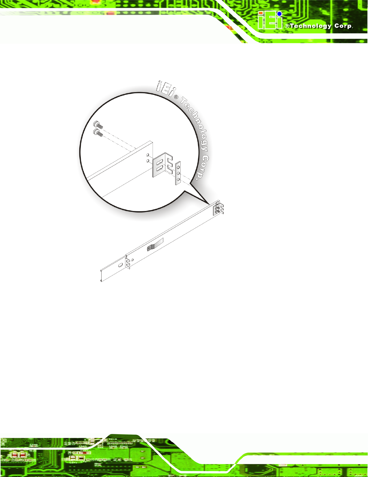
Step 3: The left and right side panels of the workstation each have five screw holes for
rack slides. Attach one slide section each to the left and right side panel of the
workstation. (See Figure 4-18)
EC-1040GB Workstation
Figure 4-18: Workstation Slide Installation (Other Side Similar)
Page 44
Page 55
EC-1040GB Workstation
Step 4: Assemble the slide brackets per the manufacturer’s instructions.
(See Figure 4-19)
Figure 4-19: Rack Slide Bracket Assembly
Page 45
Page 56

Step 5: Attach the slide brackets to the rack per the manufacturer’s instructions.
(See Figure 4-20)
EC-1040GB Workstation
Page 46
Figure 4-20: Rack Slide Bracket Installation
Page 57

EC-1040GB Workstation
Step 6: Insert the workstation with the attached slides into the rack slide brackets until
the handle brackets are flush against the rack. (See Figure 4-21)
Figure 4-21: Install Workstation into Rack
Step 7: If necessary, secure the workstation handle brackets to the rack with the
fasteners that came with the workstation.
Step 0:
Page 47
Page 58

EC-1040GB Workstation
Chapter
5
5 Maintenance
Page 48
Page 59

EC-1040GB Workstation
5.1 Maintenance Overview
Maintaining the EC-1040GB rackmount workstation is essential for the smooth operating
of system applications. Maintaining the system might mean replacing failed components
during the lifetime of the workstation. The following EC-1040GB components can be
replaced.
CPU card
PCI/ISA exp ansion card
Backplane
Power supply unit (PSU)
Cooling fans
Disk drives
o 3.5”
o 5.25”
WARNING:
Never attempt to remove the external panels or access any internal
components of the workstation while it is connected to a power source. Always
be sure to turn off and disconnect the workstation from all power sources
before attempting to access the internal components. Failure to do so may
seriously injury to the user or cause irreparable damage the internal
components of the workstation.
Page 49
Page 60

5.2 CPU Card Replacement
To replace a CPU card, please follow the instructions below.
Step 1: Turn off and disconnect the workstation from all power sources.
Step 2: Remove the workstation from the rack in which it is installed.
Step 3: Open the top cover of the EC-1040GB rackmount workstation.
(See Section 4.5.1)
Step 4: Disconnect all internal and external peripheral devi ce con ne ctions from the CP U
card.
Step 5: Remove the CPU card clamp. (See Section 4.5.2)
Step 6: Remove the retention screw that secures the CPU card to the slot on the rear
EC-1040GB Workstation
panel.
Step 7: Slide the CPU card out of the workstation.
Step 8: Install a new CPU card. (See Section 4.5.9)
Step 9: Reinstall the CPU card clamp.
Step 10: Reinstall the top cover of the workstation. (See Section 4.5.9)
Step 11: Reinstall the workstation into the rack. Refer to Section 4.6 for complete
mounting instructions.Step 0:
5.3 PCI/ISA Expansion Card Replacement
To replace a PCI/ISA expansion card, please follow the instructions below.
Step 1: Turn off and disconnect the workstation from all power sources.
Step 2: Remove the workstation from the rack in which it is installed.
Page 50
Step 3: Open the top cover of the EC-1040GB rackmount workstation.
(See Section 4.5.1)
Page 61

EC-1040GB Workstation
Step 4: Disconnect all internal and external peripheral device connections from the
PCI/ISA expansion card.
Step 5: Remove the CPU card clamp. (See Section 4.5.2)
Step 6: Remove the retention screw that secures the PCI/ISA expansion card to the slot
on the rear panel.
Step 7: Slide the PCI/ISA expansion card out of the workstation.
Step 8: Install a new PCI/ISA expansion card. (See Section 4.5.9)
Step 9: Reinstall the CPU card clamp.
Step 10: Reinstall the top cover of the workstation. (See Section 4.5.9)
Step 11: Reinstall the workstation into the rack. Refer to Section 4.6 for complete
mounting instructions.Step 0:
5.4 Backplane Replacement
To replace a backplane, please follow the instructions below.
Step 1: Turn off and disconnect the workstation from all power sources.
Step 2: Remove the workstation from the rack in which it is installed.
Step 3: Open the top cover of the EC-1040GB rackmount workstation.
(See Section 4.5.1)
Step 4: Remove the CPU card clamp. (See Section 4.5.2)
Step 5: Disconnect and remove all CPU cards (see Section 4.5.9) and PCI/ISA
expansion cards (see Section 4.5.10).
Step 6: Remove the retention screws that secure the backplane to the workstation
(see Section 4.5.8).
Step 7: Install a new backplane into the chassis.
Page 51
Page 62

Step 8: Reinstall and reconnect all CPU cards (see Section 4.5.9) and PCI/ISA
EC-1040GB Workstation
expansion cards (see Section 4.5.10).
Step 9: Reinstall the CPU card hold down bar.
Step 10: Close the back cover of the workstation and reinstall the workstation into the
cabinet or rack in which it was previously installed. Refer to Section
complete mounting instructions.
5.5 PSU Replacement
To replace a PSU, please follow the instructions below.
Step 1: Turn off and disconnect the workstation from all power sources.
Step 2: Remove the workstation from the rack in which it is installed.
Step 3: Open the top cover of the EC-1040GB rackmount workstation.
(See Section 4.5.1)
4.6 for
Step 4: Disconnect all the PSU cables from their devices.
Step 5: Remove the three external retention screws that secure the PSU assembly to
the rear panel of the workstation (
Figure 5-1: PSU External Retention Screws
Figure 5-1).
Page 52
Page 63

EC-1040GB Workstation
Step 6: Remove the two internal retention screws that secure the PSU assembly to the
right side panel of the workstation (Figure 5-2).
Figure 5-2: PSU Internal Retention Screws
Step 7: Remove the two retention screws on the PSU mounting bracket (Figure 5-3).
Page 53
Page 64

EC-1040GB Workstation
Figure 5-3: PSU Mounting Bracket Retention Screws
Step 8: Reattach the PSU mounting bracket to the new PSU with the two previously
removed retention screws.
Step 9: Install the new PSU into the workstation making sure the PSU power co nnector
and PSU cooling fan are facing out of the workstation.
Step 10: Reinsert the two previously removed internal retention screws that secure the
PSU assembly to the right side panel of the workstation.
Step 11: Reinsert the three previously removed external retention screws that secure the
PSU assembly to the rear panel of the workstation.
Step 12: Close the back cover of the workstation and reinstall the workstation into the
cabinet or rack in which it was previously installed. Refer to Section
complete mounting instructions.
4.6 for
Page 54
Page 65

EC-1040GB Workstation
5.6 Cooling Fan Replacement
To replace a cooling fan, please follow the instructions below.
CAUTION:
Carefully note the direction and orientation of the existing cooling fan prior to
replacement.
Step 1: Turn off and disconnect the workstation from all power sources.
Step 2: Remove the workstation from the rack in which it is installed.
Step 3: Open the top cover of the EC-1040GB rackmount workstation.
(See Section 4.5.1)
Step 4: Disconnect the cooling fan from the PSU.
Step 5: Remove the defective cooling fan by pressing down on the two spring clips that
lock the fan into place until the fan is release from the CPU card slot bracket and
can be pulled out of the workstation. (See
Figure 5-4)
Page 55
Page 66

EC-1040GB Workstation
Page 56
Figure 5-4: Cooling Fan Spring Clips
Step 6: Install the new cooling fan.
Step 7: Connect the new cooling fan to the PSU.
Step 8: Close the top cover of the workstation and reinstall the workstation into the
cabinet or rack in which it was previously installed. Refer to Section
complete mounting instructions. Step 0:
4.6 for
Page 67

EC-1040GB Workstation
5.7 Disk Drive Replacement
5.7.1 3.5” Disk Drive Replacement
To replace a 3.5” disk drive, please follow the instructions below.
Step 1: Turn off and disconnect the workstation from all power sources.
Step 2: Remove the workstation from the rack in which it is installed.
Step 3: Open the top cover of the EC-1040GB rackmount workstation.
(See Section 4.5.1)
Step 4: Disconnect all cabling from every hard drive.
Step 5: Remove the drive bracket (see Section 4.5.3).
Step 6: Remove the retention screws that secure the 3.5” disk drive to the drive bracket
and slide the drive out of the bracket.
Step 7: Install the new 3.5” disk drive. (See Section 4.5.6.3)
Step 8: Reinstall the drive bracket to the workstation. (See Section 4.5.7)
Step 9: Reconnect all disk drive cabling.
Step 10: Close the top cover of the workstation and reinstall the workstation into the
cabinet or rack in which it was previously installed. Refer to Section
complete mounting instructions. Step 0:
4.6 for
Page 57
Page 68

5.7.2 5.25” Disk Drive Replacement
To replace a 5.25” disk drive, please follow the instructions below.
NOTE:
These instructions are also applicable for replacement of a 3.5” disk drive
mounted in a 5.25” disk drive adapter bracket. Refer to Section 4.5.6.2 for
instructions on installing a 3.5” disk drive into a 5.25” drive bay slot.
Step 1: Turn off and disconnect the workstation from all power sources.
Step 2: Remove the workstation from the rack in which it is installed.
Step 3: Open the top cover of the EC-1040GB rackmount workstation.
EC-1040GB Workstation
(See Section 4.5.1)
Step 4: Disconnect all cabling from every hard drive.
Step 5: Remove the drive bracket (See Section 4.5.3).
Step 6: Remove the 3.5” drive bracket (See Section 4.5.5).
Step 7: Remove the retention screws that secure the 5.25” disk drive to the drive
bracket and slide the drive out of the bracket.
Step 8: Install the new 5.25” disk drive. (See Section 4.5.6.1)
Step 9: Reinstall the drive bracket to the workstation. (See Section 4.5.7)
Step 10: Reconnect all disk drive cabling.
Step 11: Close the top cover of the workstation and reinstall the workstation into the
cabinet or rack in which it was previously installed. Refer to Section
complete mounting instructions. Step 0:
4.6 for
Page 58
Page 69

EC-1040GB Workstation
Chapter
6
6 On Screen Display (OSD)
Controls
Page 59
Page 70

6.1 User Mode OSD Structure
6.1.1 OSD Buttons
There are several on-screen-display (OSD) control buttons oriented vertically along the
EC-1040GB Workstation
right hand side of the LCD screen.
buttons.
Figure 6-1 shows the arrangement of OSD control
Page 60
Figure 6-1: OSD Control Buttons
NOTE:
Pressing the direction keys (LEFT or RIGHT) can bring out a simple menu to
adjust the LCD screen brightness and contrast values.
Page 71

EC-1040GB Workstation
6.1.2 OSD Menu Structure
Table 6-1 shows the OSD menu structure.
Level 0 Level 1 Value
Color Contrast 0 to 100
Brightness 0 to 255
Color Adjust 0 to 255
Color Temp 9300
6500
Back
Image Setting Clock 0 to 100
Phase 0 to 63
Gamma 0, 1, 2, 3
Sharpness 0, 1, 2, 3, 4
Back
Position H Position 0 to 200
V Position 0 to 36
Back
OSD Menu OSD H Position 0 to 200
OSD V Position 0 to 200
OSD Timer 0 to 27
Back
5800
sRGB
USER
Language Menu English
French
German
Spanish Select
Traditional Chinese
Simplified Chinese
Japanese
Misc. Signal Source Select
Page 61
Page 72

Level 0 Level 1 Value
Reset
Info.
Back
Exit
Table 6-1: OSD Menu Structure
6.1.3 Main Menu
The main menu is shown in Figure 6-2.
EC-1040GB Workstation
Figure 6-2: Main Menu
All sub-menus accessible from the main menu are further described in the sectio ns below.
6.1.4 Color Menu
Color menu options are shown in Figure 6-3.
Page 62
Page 73

EC-1040GB Workstation
Figure 6-3: Color Menu
The Color menu adjusts the brightness and contrast and fine-tunes the palette of color
hues for the LCD.
Contrast:
Adjusting this value too high or too low will worsen the quality of image.
Brightness:
Setting this value too high or too low will affect the quality of image.
Color Adjust:
Adjusts the color of user mode settings.
Color Temperature:
9300: NTSC standard Kelvin
6500: NTSC standard Kelvin
5800: NTSC standard Kelvin
sRGB: Sets the color temperature to sRGB
User: Sets the color temperature to User
Back:
This item returns to the main menu.
Page 63
Page 74

6.1.5 Image Setting Menu
Image Setting menu options are shown in Figure 6-4.
EC-1040GB Workstation
Figure 6-4: Image Setting Menu
The Image Setting menu adjusts the display signal settings.
Clock:
This option adjusts the display width.
Phase:
This option adjusts the input signal and dot clock position (Analog only).
Gamma:
Adjusts the gamma level to one of the 4 preset values.
Sharpness:
Adjusts the sharpness level to one of the 5 preset values. This option may
help reducing the softening edges around displayed objects.
Back:
This item returns to the main menu.
Page 64
Page 75

EC-1040GB Workstation
6.1.6 Position Menu
The Position menu options are shown in Figure 6-5.
Figure 6-5: Image Menu
The Position menu adjusts the screen position options.
H Position:
This item adjusts the horizontal position of the display screen.
V Position:
This item adjusts the vertical position of the display screen.
Back:
This item returns to the main menu.
Page 65
Page 76

6.1.7 OSD Menu
The OSD menu is shown in Figure 6-6.
EC-1040GB Workstation
Figure 6-6: OSD Menu
The OSD menu adjusts the OSD screen options.
OSD H Position:
This item adjusts the horizontal position of the OSD display screen.
OSD V Position:
This item adjusts the vertical position of the OSD display screen.
OSD Timer:
This item adjusts how many seconds the OSD screen st ays visib le before
it disappears when OSD is left unattended.
Back:
This item returns to the main menu.
Page 66
Page 77

EC-1040GB Workstation
6.1.8 Language Menu
The Language menu options are shown in Figure 6-7.
Figure 6-7: Language Menu
The Language menu provides options for selectin g OSD screen s in a preferred langu age.
Page 67
Page 78

6.1.9 Misc. Menu
The Misc. menu options are shown in Figure 6-8.
EC-1040GB Workstation
Figure 6-8: Misc. Menu
The Misc. menu has the following options.
Signal Source:
This item enables manual selection of the type of graphic source input,
i.e., analog (15-pin VGA) or digital (DVI-D).
Reset:
This item resets the display to factory default.
Info:
This item displays information on the screen resolution.
Back:
This item returns to the main menu.
Page 68
Page 79

EC-1040GB Workstation
Chapter
8
7 A106 Utility
Page 69
Page 80

7.1 A106 Utility Overview
The EC-1040GB workstation has a preinstalled A106 alarm board. The main function of
the A106 alarm board is to check whether the temperatures in the chassis and the speed
of the fans is normal. It also monitors the system via an external Watchdog timer providing
feedback as to whether the system is working properly or has dropped halt.
The A106 alarm board is connected to several critical system components as well as the
front panel LEDs and buzzer to notify the user in case of system fan failure or if high
temperatures are sensed in the workstation.
For more information on programmable features of the A106 alarm board, refer to the
documentation contained on the utility CD included with the workstation.
Figure 8-1 shows the cabling of the workstation components to the A106 alarm board.
EC-1040GB Workstation
Figure 7-1: A106 Alarm Board Cabling
Page 70
Page 81

EC-1040GB Workstation
Appendix
A
A Certifications
Page 71
Page 82

A.1 RoHS Compliant
All EC-1040GB rackmount workstations comply with the Restriction of Hazardous
Materials (RoHS) Directive. This means that all components used to build the industrial
workstations and the workstation itself are RoHS compliant.
The RoHS Directive bans the placing on the EU market of new electrical and electronic
equipment containing more than agreed levels of lead, cadmium, mercury, hexavalent
chromium, polybrominated biphenyl (PBB) and polybrominated diphenyl ether (PBDE)
flame retardants.
EC-1040GB Workstation
Page 72
Page 83

EC-1040GB Workstation
Appendix
B
B Recommended IEI
Backplanes,
Motherboards
and PSUs
Page 73
Page 84

The following IEI backplanes, motherboards and power supply units are re comme nded for
the EC-1040GB rackmount workstation. For more information about these backplanes
EC-1040GB Workstation
please contact an IEI sales representative or visit the IEI website (
www.ieiworld.com).
B.1 Recommended IEI Backplanes and Motherboards
The following table lists the recommended IEI backplanes and motherboards for the
EC-1040GB rackmount workstation.
PCIe
Model No. SBC Type PCI ISA
X1 X4 X16
PCI-13SD-RS-R30 PICMG 1.0 3 + 4 3 + 3 0 0 0 AT/ATX
PCI-14S2-RS-R30 PICMG 1.0 4 8 0 0 0 AT/ATX
PCI-14S3-RS-R30 PICMG 1.0 4 9 0 0 0 AT/ATX
PX-14S3-RS-R30 PICMG 1.0 12 2 0 0 0 AT/ATX
PX-14S5-RS-R30 PICMG 1.0 7 6 0 0 0 AT/ATX
PSU
Connector
BP-14S-RS-R30 ISA 0 14 0 0 0 AT
PXAGP-13S3-RS-R30 PIAGP 11 0 0 0 0 AT/ATX
PE-13SD PICMG 1.3 4 0 5 0 2 ATX
PXE-13S PICMG 1.3 8 0 3 0 1 ATX
PXE-13S2 PICMG 1.3 4 0 7 0 1 ATX
PXE-13S3 PICMG 1.3 3 0 0 8 1 ATX
Table B-1: Recommended IEI Backplanes and Motherboards
B.2 Recommended IEI Power Supply Units
The following table lists the recommended IEI power supply units for the EC-1040GB
rackmount workstation.
Page 74
Page 85

EC-1040GB Workstation
Type Model No. Watt
AT ACE-935AL-RS 300W
ATX ACE-841AP-RS 480W
Redundant ATX ACE-R4130AP-RS 300W
Table B-2: Recommended IEI Power Supply Units
Page 75
 Loading...