

Page 1
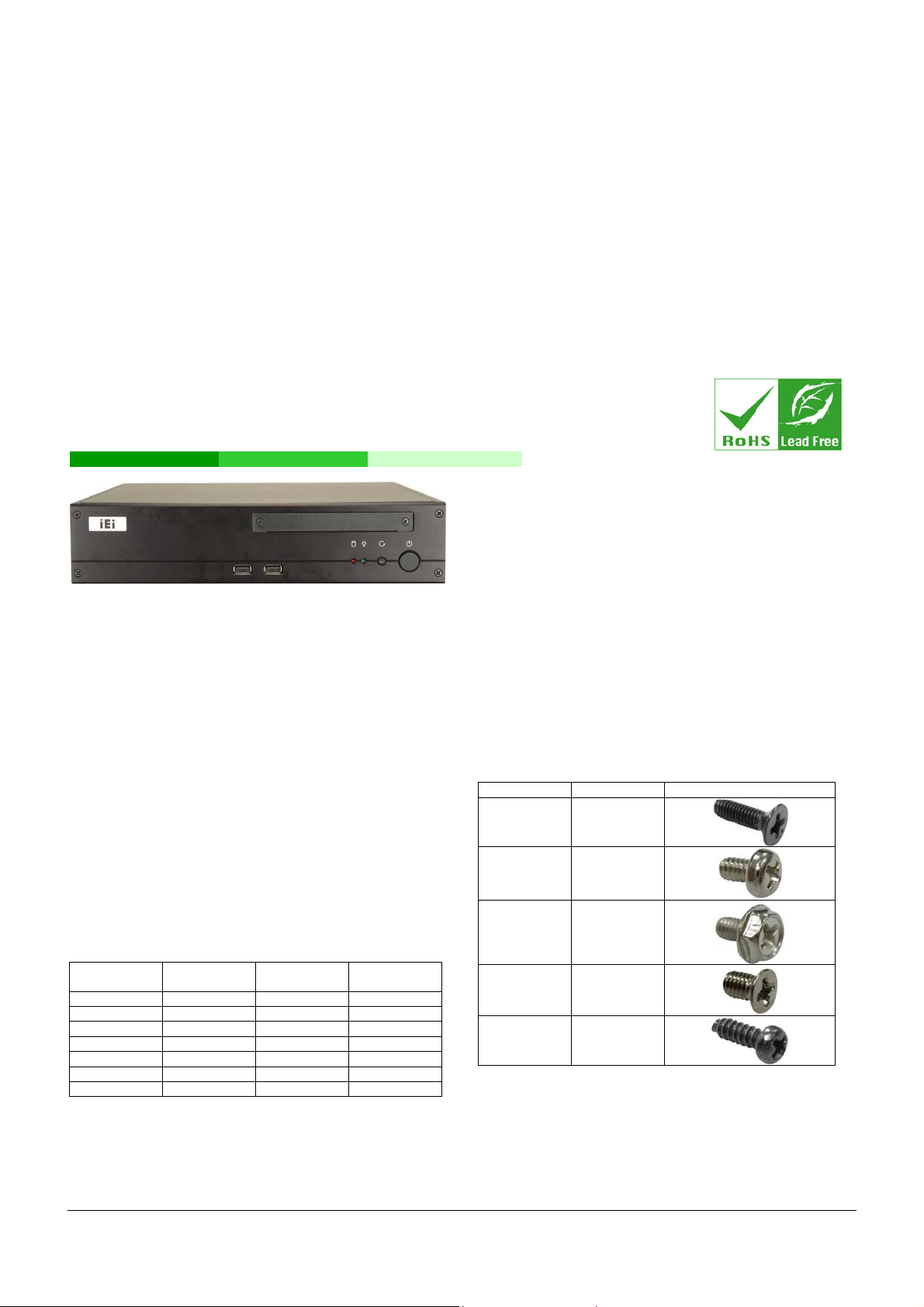
EBC-3620
Mini-ITX Chassis
Version: 1.0
Quick Installation Guide
ABOUT THE EBC-3620
The EBC-3620 is designed for Mini-ITX motherboards. The
EBC-3620 has two USB ports on the front panel, and a space for a
slim-type DVD or CD drive. Up to four drives can be installed. The
EBC-3620 also supports PCI/PCIe cards (depending on the
motherboard) through expansion card slots on the rear panel.
SPECIFICATIONS
Form Factor: Fits Mini-ITX motherboards
SBC Form Factor: Mini-ITX
Construction: Heavy-duty steel
Slots: 2 slots
Cooling: 2 x 5 cm fans
Dimensions (DxWxH):
o 300 mm x 268 mm x 65 mm
Operating Temperature: 0~50°C
Relative Humidity: 10~90%
Vibration:
o 5-17Hz, 0.1” double amplitude displacement
o 17-640Hz, 1.5G acceleration peak to peak
Shock: 10G acceleration peak to peak
Drive Bay Combinations: Listed in
Optical Drives Expansion
Cards
1 2 2 0
1 1 1 1
1 0 1 2
1 0 2 1
0 2 3 0
0 1 3 1
0 1 2 2
Table 1: Drive Combinations
Table 1 below
2.5” Hard
Drives
3.5” Hard
Drives
PACKING LIST
When unpacking the chassis, make sure the following items have
been shipped.
1 x Riser card
1 x Screw set (details below)
1 x 2.5” adapter bracket
1 x System fan cable
1 x Power adapter
1 x Power cord
DETAILS OF INCLUDED SCREWS
The attached screws include all of the following screws. Both
pre-installed screws and screws that have not been installed are
included.
Description Quantity Picture
Front cover
screws
Top cover
screws
Hard drive
bracket
screws
Support
bracket screw
DC jack
screw
Table 2: Screws for Peripheral/Parts
6
2
12
1
2
EBC-3620 IEI Technology Corp. Page 1
Page 2
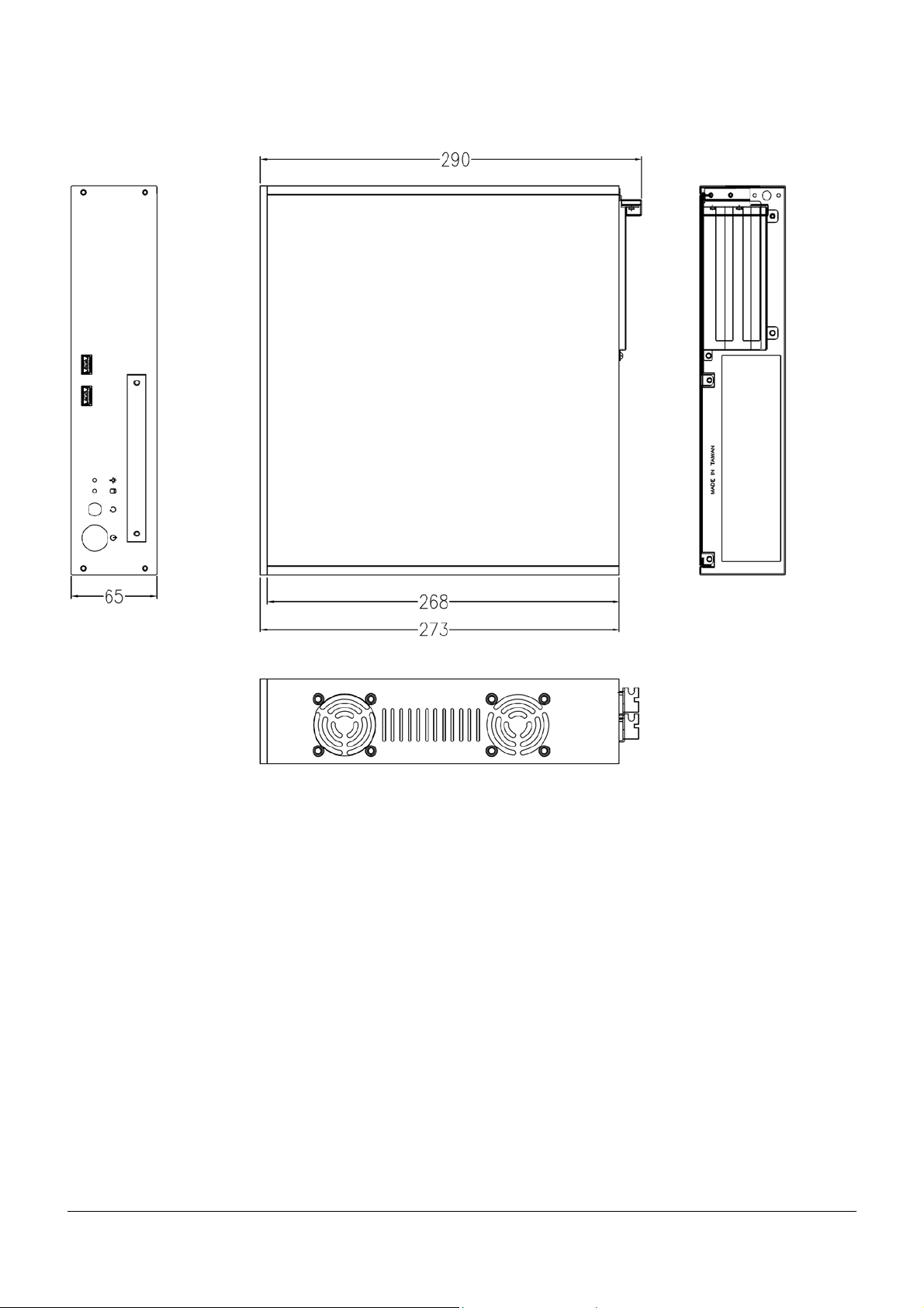
DIMENSION DRAWING
EBC-3620 dimensions are shown below.
Figure 1: Dimension Drawing (measurement in millimeters)
EBC-3620 IEI Technology Corp. Page 2
Page 3
INSTALLATION STEPS
To install the EBC-3620 chassis, the following installation steps must
be completed:
Step 1: Unpack
Step 2: Top cover and Support Bracket Removal
Step 3: Install Motherboard
Step 4: Install Optical Drive
Step 5: Install Hard Drives (Main Bracket)
Step 6: Install Hard Drive (Bottom Bracket)
Step 7: Install Expansion Card
Step 8: Front Panel Cables
Step 9: Cover Reinstallation
The installation steps outlined above are described in detail below.
Please refer to the relevant section.
STEP 1: UNPACK
The EBC-3620 is shipped in a plastic bag that is placed inside a
cardboard box. The accessories are also shipped with the chassis.
When unpacking the chassis:
Make sure all the accessories and components mentioned in
the PACKING LIST section are present.
Make sure the chassis has not been damaged in any way.
Step 4: Pull up the support bracket to remove it.Step 0:
STEP 3: INSTALL MOTHERBOARD
The motherboard is installed before all the other components in the
chassis. To install the motherboard, follow the steps below.
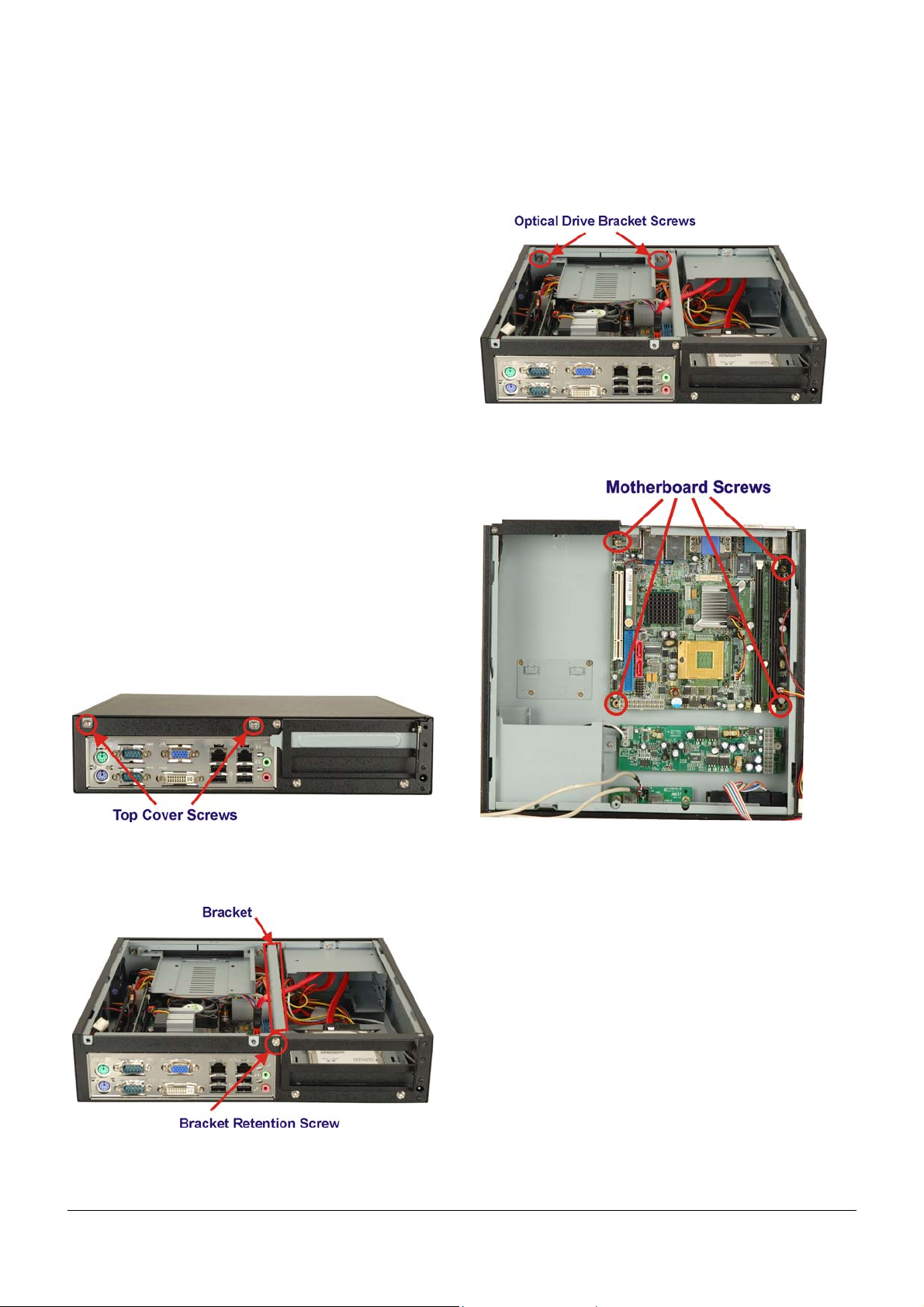
Step 1: Undo the optical disk drive screws and remove the
optical disk drive bracket.
Figure 4: Optical Drive Bracket Screws
Step 2: Place the motherboard into the chassis and fasten the
four motherboard screws.
STEP 2: TOP COVER AND SUPPORT BRACKET REMOVAL
The top cover is secured to the chassis with six retention screws,
three on each side of the chassis. To remove the top cover, please
follow the steps below.
Step 1: Remove the two top cover retention screws as
indicated below.
Figure 2: Top Cover Retention Screws
Step 2: Slide the top cover back to remove it.
Step 3: Remove the internal support bracket retention screw.
Figure 5: Optical Drive Bracket Screws
Step 3: Attach the following cables to the motherboard:
Power cable
Fan cable
USB cables
Front panel cables
o Power button cable
o Reset button cable
o Power LED cable
o Hard drive activity LED cable
Figure 3: Support Bracket Screw
EBC-3620 IEI Technology Corp. Page 3
Page 4

Figure 6: Optical Drive Bracket Screws
Step 4: Reinstall the optical drive bracket and fasten the
screws. Also attach the hard drive cables Step 0:
Step 2: Attach the optical drive screws and tighten.
Figure 8: Optical Drive Screws
Step 3: If installing a hard drive, the hard drive installs on the
top side of the optical drive bracket. Connectors face
towards the inside of the chassis The screws attach
underneath.
STEP 4: INSTALL OPTICAL DRIVE
The optical drive bracket supports either a slim-type optical drive or
2.5” hard disk. To install the optical drive or hard disk, please follow
the steps below.
Step 1: Slide the optical drive into the optical drive bracket.
Slide the optical drive from the front of the bracket.
Figure 7: Slide the Optical Drive
Figure 9: Hard Drive Screws
Step 4: If installing an optical drive in the optical drive bracket,
break the metal plates (indicated below) from the case.
Bend back and forth until they break off.
Figure 10: Optical Drive Cover
EBC-3620 IEI Technology Corp. Page 4
Page 5

Step 5: Reinstall the optical drive bracket and fasten the
screws. Also attach the hard drive cables Step 0:
Figure 11: Fasten Optical Drive Screws
STEP 5: INSTALL HARD DRIVES (MAIN BRACKET)
To install hard drives in the main hard drive bracket, follow the
instructions below.
Step 1: Undo the hard drive bracket screws indicated below.
Step 3: Install the hard drives and fasten all the hard drive
screws.
Figure 12: Hard Drive Bracket Screws
Step 2: Remove the hard drive bracket from the chassis.
Figure 13: Hard Drive Screws
Step 4: Attach the cables to the hard drives.
Figure 14: SATA Cables
Step 5: Reinstall the hard drive bracket into the chassis.
Step 0:
EBC-3620 IEI Technology Corp. Page 5
Page 6

STEP 6: INSTALL HARD DRIVE (BOTTOM BRACKET)
To install a hard drive into the hard drive bracket on the bottom of the
chassis, please follow the instructions below.
Step 1: Unfasten the single hard drive br acket screw. Slide the
hard drive bracket towards the front of the chassis to
remove.
previously removed screw. Step 0:
STEP 7: INSTALL EXPANSION CARD
The EBC-3620 supports up to two expansion cards. To install the
expansion cards, please follow the instructions below.
Step 1: Undo the expansion slot cover screw. Pull it out in the
direction shown.
Figure 17: Expansion Card Slot Cover
Figure 15: Install 1
Step 2: Install a hard drive in the hard drive bracket and fasten
the screws indicated below.
Step 2: Secure the p ower supply bracket to the power supply
and then secure the power supply bracket to the
system panel.
Figure 18: Expansion Card Installation
Step 3: Attach the riser card to the PCI card.
Press the riser card into the expansion slot.
Figure 16: Hard Drive Screws
Step 3: Attach the cables to the hard drive (
Step 4: Reinstall the hard drive bracket and fasten the
Figure 14)
Figure 19: Riser Card Installation
EBC-3620 IEI Technology Corp. Page 6
Page 7

Step 4: Fasten the expansion card retention screw.
Figure 20: Expansion Card Retention Screw
No. Name
1
Power LED cable
1
Reset Switch cable
1
HDD LED cable
1
Power switch cable
1
Step 5: Optionally attach the expansion screw cover and
fasten the two screws. Step 0:
Figure 21: Expansion Card Screw Cover
STEP 8: FRONT PANEL CABLES
The following buttons, LEDs and USB port are on the front panel of
the EBC-3620 chassis.
o 1 x Power LED
o 1 x HDD LED
o 1 x Power switch
o 1 x Reset button
o 2 x USB ports
o 1 x Backplane ATX connector
These components are all connected to the CPU card with cables.
To correctly connect these cables, please refer to the technical
documentation that came with your CPU card. The connectors that
are provided with the chassis are listed below.
No. Name
2
USB cable
Backplane ATX connector cable
Table 3: Chassis Connectors
USB cable pin definitions are shown below
PIN No. Description Color
1 +5V Red
2 D- White
3 D+ Green
4 GND Black
Table 4: USB Cable Pinouts
STEP 9: COVER REINSTALLATION
Cover reinstallation is in the reverse order of removal.
Step 1: Position the internal support bracket and fasten the
screw.
Step 2: Reinstall cover and fasten the two screws. Step 0:
CHASSIS MAINTENANCE FAN REPLACEMENT
NOTE:
Please ensure that the power of the computer is switched off before
fan replacement procedure.
There are two cooling fans inside the EBC-3620 chassis. To replace
them, please follow the instructions below.
Step 1: Open the chassis (refer to
Figure 2)
EBC-3620 IEI Technology Corp. Page 7
Page 8

Step 2: Remove the fan screws.
Figure 22: Fan Screws
Step 3: Slide the fan out of the chassis and remove the fan
power cable.
Figure 23: Fan Location
Step 4: To reinstall the fan, reverse the procedure. Step 0:
EBC-3620 IEI Technology Corp. Page 8
 Loading...