

Page 1
EBC-3200
Chassis for Mini-ITX
Version: 1.01
Quick Installation Guide
ABOUT THE EBC-3200
The heavy-duty steel EBC-3200 compact embedded industrial
chassis is designed for Mini-ITX SBC to operate reliably in industrial
environments where it will be exposed to dust, wide temperature
variations, shocks and vibrations.
SPECIFICATIONS
SBC Form Factor: Mini-ITX SBC
Construction: Heavy duty metal
Drive Bays:
o Two 2.5” Internal HDD bays (standard) or
o One 2.5” Internal HDD bay and one CF card slot
Expansion: One PCI or PCIe riser card (optional)
USB: Two front accessible USB ports
Indicator and Switch:
o 1 x Power LED
o 1 x HDD LED
o 1 x Reset button
o 1 x Power switch
Mount:
o Wall mount (mounting plates included)
o VESA 100 mount
Dimensions (WxDxH):
o 260 mm x 180 mm x 55 mm
Operating Temperature: -10°C ~ 50°C with air flow
(Ambient air speed per IEC-68-2-2 standard)
Relative Humidity: 10%~90%
Weight (N): 1.5 kg
PACKING LIST
When unpacking the chassis, make sure the following items
have been shipped.
1 x Quick Installation Guide
1 x Power cord
1 x Screw set
2 x Wall mount brackets
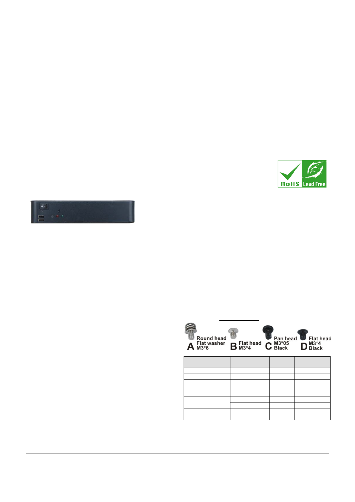
DETAILS OF INCLUDED SCREWS
Screws used for chassis installation
Peripherals/Parts
Top Cover D 2 On chassis
2.5” HDD B 8 In package
Motherboard A 4 In package
Bracket
USB Module Bracket D 2 On chassis
Wall-mount Bracket C 4 In package
Table 1: Screws for Peripheral/Parts
Screw Label
(refer to picture)
are shown below.
Amount
D 2 On chassis HDD Bracket
B 1 On chassis
C 2 On chassis Expansion Slot
B 2 On chassis
In Package/
On Chassis
EBC-3200 QIG IEI Technology Corp. Page 1
Page 2

DIMENSION DRAWING
The dimensions of EBC-3200-8522 are shown below.
Figure 1: Dimension Drawing
OPTIONAL MODULES
The EBC-3200 also supports CF slot module as well as PCI or PCIe riser card depending on which motherboard is installed. The
optional module includes:
Part No. Description and Picture
EBCKIT-01-R10/PCI-HDD
EBCKIT-02-R10/PCIe-HDD
EBCKIT-03-R10/PCI-CF
EBCKIT-04-R10/PCIe-CF
EBCKIT-05-R10/CF-HDD
One PCI slot riser card
One PCIe slot riser card
One PCI slot riser card
One PCIe slot riser card
One 2.5” HDD bay
One PCIe slot riser card
One 2.5” HDD bay
One 2.5” HDD bay
CF slot module
CF slot module
CF slot module
One 2.5” HDD bay
Expansion slot bracket
Expansion slot bracket
Expansion slot bracket
Expansion slot bracket
Expansion slot bracket
Expansion slot bracket
EBCKIT-06-R10/PCIe16-HDD
EBCKIT-07-R10/PCIe16-CF
Table 2: Optional Modules
One PCIe slot riser card
CF slot module
Expansion slot bracket
EBC-3200 QIG IEI Technology Corp. Page 2
Page 3

INSTALLATION STEPS
To install the EBC-3200 chassis, the following installation steps must
be completed:
Step 1: Unpack the chassis.
Step 2: Remove the top cover.
Step 3: Install the SBC (Single Board Computer).
Step 4: Install the CF slot module. (optional)
Step 5: Install the internal 2.5” HDD.
Step 6: Install the PCIe/PCI riser card. (optional)
STEP 3: MOTHERBOARD
INSTALLATION
To install a Mini-ITX motherboard, please follow the instructions
below:
Step 1: Remove the USB module bracket from the
chassis by removing the two retention screws on
the front panel.
Step 7: Connect the cables.
Step 8: Reinstall the top cover.
Step 9: Mount the chassis. (optional) Step 0:
The installation steps outlined above are described in detail below.
Please refer to the relevant section.
STEP 1: UNPACK
The EBC-3200 is shipped in a plastic bag that is placed inside a
cardboard box. The items are also shipped with the chassis. When
unpacking the chassis please:
Make sure all the items listed in the PACKING LIST
section are present.
Make sure the chassis has not been damaged in any
way.
STEP 2: REMOVE THE TOP COVER
The top cover is secured to the chassis with two thumb
screws on the rear panel of the chassis.
Step 1: Loosen the two top cover thumb screws at the
rear panel of the chassis.
Figure 3: USB Module Bracket Retention Screws
Step 2: Remove the expansion slot bracket shown in the
following diagram from the chassis by removing
the four retention screws.
Figure 4: Expansion Slot Bracket Retention Screws
Step 3: Install the I/O shielding in the chassis. Push the
I/O shielding inside out.
Figure 5: I/O Shielding Installation
Step 4: Place the motherboard inside the right hand side
of the chassis. Make sure the external peripheral
interface connectors fit into the predrilled holes
on the previously installed I/O shielding.
motherboard with the retention screw holes on
the bottom of the chassis.
Figure 2: Top Cover Retention Screws
Step 2: Slide the cover forwards and then lift the cover up
gently.Step 0:
Step 5: Align the four retention screws holes on the
Step 6: Install the motherboard to the chassis with four
EBC-3200 QIG IEI Technology Corp. Page 3
Page 4

retention screws.
Figure 6: Motherboard Retention Screws
Step 7: Reinstall the two brackets removed in Step 1 and
Step 2. Step 0:
STEP 4: CF MODULE INSTALLATION
(OPTIONAL)
To install the optional CF module, please follow the steps
below.
Figure 8: CF Module Installation
STEP 5: DISK DRIVE INSTALLATION
The EBC-3200 chassis has the capacity for one or two 2.5”
internal HDD. To install the HDD, please follow the steps
below.
Step 1: Remove the HDD bracket from the chassis by
removing three retention screws, two on the left
panel and one inside the chassis.
Step 1: Remove the expansion slot bracket.
Step 2: Mount the CF module onto the HDD bracket. To
do this, align the four retention screw holes in the
CF module with the retention screw holes in the
HDD bracket.
Step 3: Insert the four retention screws to secure the CF
module with the bracket.
Figure 7: CF Module Installation
Step 4: Reinstall the expansion slot bracket. Step 0:
Inside
Left Panel
Figure 9: HDD Installation
Step 2: Mount a 2.5” HDD onto the HDD bracket. To do
this, align the four retention screw holes in the
sides of 2.5” HDD with the retention screw
holes in the HDD bracket.
Step 3: Insert the four retention screws to secure the
HDD with the bracket.
EBC-3200 QIG IEI Technology Corp. Page 4
Page 5

Figure 10: HDD Retention Screws
Step 4: Install the HDD into the chassis with three
retention screws.
Figure 11: HDD Installation
STEP 6: RISER CARD INSTALLATION
(OPTIONAL)
To install the optional PCI/PCIe riser card, please follow the
steps below.
Step 1: Remove the expansion slot bracket.
Step 2: Locate the PCI or PCIe slot on the motherboard.
Step 3: Insert the PCI or PCIe riser card into the PCI or
PCIe slot on the motherboard.
Step 5: Reinstall the expansion slot bracket.
Step 6: Secure the expansion card with the chassis by
one retention screw. Step 0:
Figure 13: PCI/PCIe Expansion Card Installation
STEP 7: CABLING
STEP 5.1: FRONT PANEL CABLE CONNECTION
There are buttons, LEDs and ports on the front panel of the
EBC-3200 chassis.
o 1 x Power LED
o 1 x HDD LED
o 1 x Power switch
o 1 x Reset button
o 2 x USB ports
These components are all connected to the motherboard
with cables. To correctly connect these cables, please refer
to the user manual that came with the motherboard. The
connectors that are provided with the chassis are listed
below.
No. Name
1
Power LED cable
1
Reset Switch cable
1
Figure 12: PCI/PCIe Riser Card Installation
Step 4: Insert the PCI or PCIe expansion card into the
PCI or PCIe slot on the riser card.
HDD LED cable
1
Power switch cable
EBC-3200 QIG IEI Technology Corp. Page 5
Page 6

2
USB cable
Table 3: Chassis Connectors
The pin definitions for the USB cable are shown below.
PIN No. Description Color
1 +5V Red
2 D- Dark Yellow
3 D+ Yellow
4 GND Brown
Table 4: Pin Definitions of USB Cable
TEP 5.2: FAN CABLE CONNECTION
S
To correctly connect the system fan cable from the system fan to the
motherboard, please refer to the user manual that came with the
motherboard.
TEP 5.3: HDD CABLE CONNECTION
S
To correctly connect the HDD SATA cable and SATA power
cable from the HDD to the motherboard, please refer to the
user manual that came with the motherboard.
STEP 8: WALL-MOUNT PLATES
INSTALLATION
Two wall-mount plates are shipped with the EBC-3200 chassis. The
wall-mount plates are installed on the sides, at the bottom of the
chassis. Each plate is secured to the chassis by two retention
screws. To install the wall-mount plates, please follow the steps
below.
Step 1: Align the retention screw holes in the wall-mount
plate with the retention screw holes on the side of
the chassis.
Figure 14: Wall-mount Plate Retention Screws
Step 2: Insert two retention screws for each wall-mount
plate.Step 0:
EBC-3200 QIG IEI Technology Corp. Page 6
 Loading...