

Page 1
EBC-3000
Mini-ITX Chassis for High Power
Consumption Applications
Version: 1.0
Quick Installation Guide
Operating humidity 10% ~90%
ABOUT
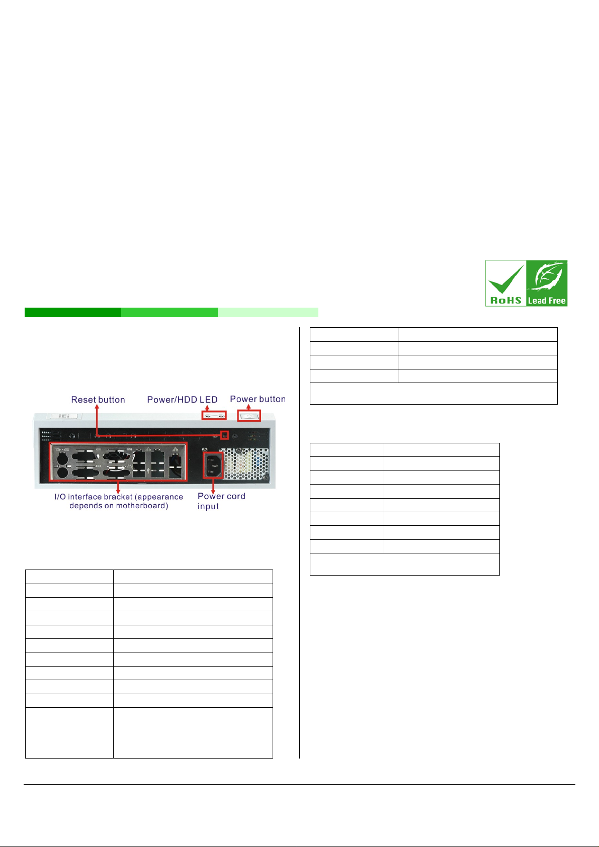
The EBC-3000EBC-3000 is designed for Mini-ITX motherboards. The
front panel includes spaces for an I/O interface panel and optional I/O
ports. One HDD drive may be installed.
EMC/Safety CE, FCC class A
Weight (Net/Gross) 2.5Kg / 3.9Kg
Dimensions (DxWxH) 230 mm x 280 mm x 88 mm
Table 1: Specifications
COMPATIBLE SBC/COOLING KIT
Compatible SBC Recommended cooling kits
KINO-9654G4 CF-520-RS, CF-775B-RS
KINO-9454 CF-520-RS, CF-775B-RS
KINO-9652 CF-479B-RS
KINO-9453 CF-479B-RS
Figure 1: Chassis Front Panel
SPECIFICATIONS
Specifications EBC-3000-R10
SBC Form Factor Mini-ITX
Drive Bays One 3.5” HDD
System Cooling fan One 6cm fan
I/O Ports Depends on SBC
Indicators Power, HDD LED
Buttons Power, Reset
Chassis construction Heavy duty metal with plastic front panel
Color Black
Mounting Desktop, wall mount
Operating
temperature
0°C~40°C (*Operating temperature is
determined by system thermal test
running with KINO-9654G4,Pentium IV
3.4GHz processor 651 and 2GB DDR2
RAM.)
KINO-9452 CF-479B-RS
KINO-690AM2 CF-AM2-RS
KINO-761AM2 CF-AM2-RS
Table 2: Compatible SBC and Cooling Kit
POWER SUPPLY SPECIFICATIONS
The EBC-3000 embedded chassis is shipped with a power supply. The
specifications for each option are listed below.
EBC-3000 IEI Technology Corp. Page 1
Page 2
Specifications ACE-A627A-RS
Input Type 90~264 VAC Full Range
Output Voltage
Efficiency 80%
Temperature Operating : 0˚C ~ 50˚C Storage : -20˚C ~ 80˚C
MTBF(hrs) 100,000 hrs
Output
Connector
Dimensions 150 x 81.5 x 40.5 (mm)
Table 3: ACE-A627A-RS Specifications
+3.3 V +5 V +12 V +12 V 2 -12 V +5 Vsb
16 A
(0.5 A min)
20-pin ATX, 4-pin 12 V, FDD and 3 x HDD
18 A
(0.5 A min)
16 A
(1 A min)
10 A
(1 A min)
0.8 A
(0 A min)
Specifications ACE-A618A-RS
Input Type 90~264 VAC Full Range
+3.3 V +5 V +12 V -12 V +5 Vsb
Output Voltage
Efficiency 68%
Temperature Operating : 0˚C ~ 50˚C Storage : -20˚C ~ 80˚C
14 A
(0.3 A min)
16 A
(0.3 A min)
14 A
(1.5 A min)
0.5 A
(0 A min)
2.0 A
(0 A min)
2.5 A
(0 A min)
MTBF(hrs)
Output
Connector
Dimensions 150 x 81.5 x 40.5 (mm)
Table 4: ACE-A618A-RS Specifications
100,000 hrs
20-pin ATX, 4-pin 12 V, FDD and 3 x HDD
PACKING LIST
EBC-3000-R10/ACE-A627A or EBC-3000-R10/ACE-A618A
Quick Installation Guide
Power cord
SATA cable for slim type ODD
Screw set
Wall mount kit
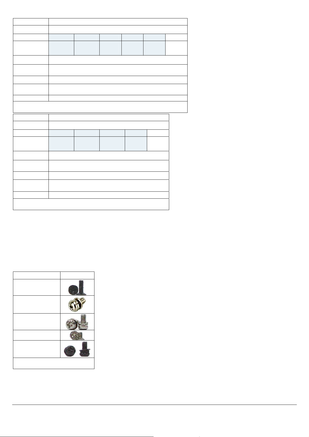
SCREW SET DETAILS
Part/Peripheral Screw Type
? (4)
HDD (6)
SBC (4)
HDD/ODD bracket (4)
Wall mount bracket (6)
Table 5: Screw Set Details
EBC-3000 IEI Technology Corp. Page 2
Page 3
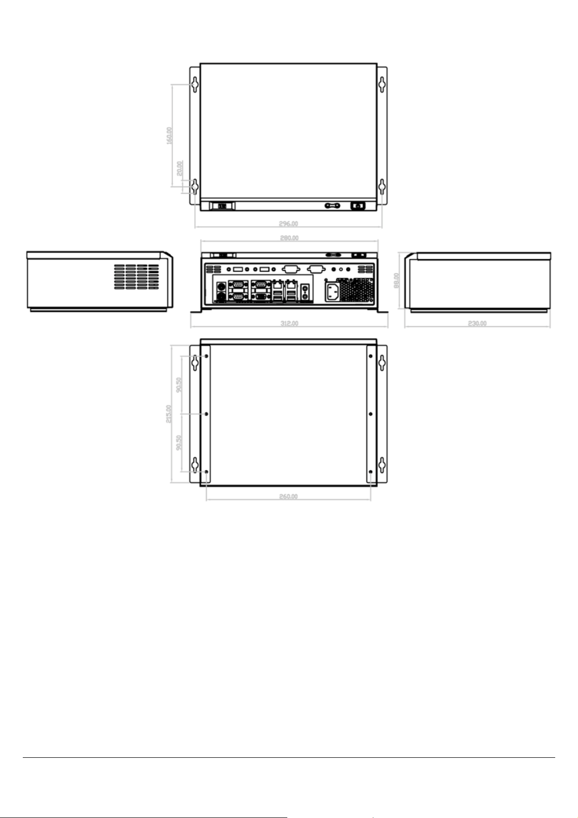
DIMENSION DRAWING
Figure 2: Dimension Drawing (measurement in millimeters)
EBC-3000 IEI Technology Corp. Page 3
Page 4

INSTALLATION STEPS
To install the EBC-3000 chassis, the following installation steps must be
completed:
1. Remove Chassis Cover
2. Install I/O Bracket
3. Install SBC
4. Install HDD
5. Front Panel Connections
6. Reinstall Chassis Cover
7. Wall Mounting (optional)
The installation steps outlined above are described in detail below. Please
refer to the relevant section.
INSTALL I/O BRACKET
Note: I/O brackets differ in appearance depending on the SBC model to be
installed in the EBC-3000.
Step 1: Snap the I/O bracket into place from the inside of
the chassis.
UNPACK
The RACK-4000B is shipped in a plastic bag that is placed inside a
cardboard box. The accessories are also shipped with the chassis. When
unpacking the chassis:
Make sure all the accessories and components mentioned in the
PACKING LIST section are present.
Make sure the chassis has not been damaged in any way
REMOVE CHASSIS COVER AND HDD
BRACKET
Step 1: Remove the chassis cover retention screw on the
rear panel (
Figure 3: Chassis Cover Retention Screws
Figure 3).
Step 2: Push the cover back to separate it from the chassis
until the cover case can be lifted from the chassis
Figure 5: I/O Bracket Installation
INSTALL SINGLE BOARD COMPUTER (SBC)
To install a Single Board Computer (SBC) with cooling kit into the chassis,
please follow these steps:
Step 1: Mount the SBC on the four metal posts on the
bottom of the chassis. Make sure the SBC I/O
interface panel is aligned with the I/O bracket.
Step 3: Remove HDD bracket. The bracket is attached to
the chassis by four retention screws (
Remove the retention screws.
Figure 4).
Figure 6: SBC Retention Screws
Step 2: Align the retention screw holes on the SBC with the
metal post retention screw holes.
Step 3: Insert the four retention screws to secure the SBC
to the chassis.
Step 4: Connect the power supply to the SBC according to
the SBC user manual.
INSTALL HDD
To install a 3.5” SATA HDD, please follow the steps below.
Step 1: Attach the HDD to the HDD bracket. To do this,
slide the HDD into the HDD bracket with the SATA
cable and power connects at the rear of the bracket
as shown in the figure below.
Figure 4: HDD Bracket Retention Screws
EBC-3000 IEI Technology Corp. Page 4
Page 5

Figure 7: HDD Bracket (Top)
Step 2: Attach the HDD to the HDD bracket. Align the
retention screw holes in the sides of the bracket
with the retention screw holes on the HDD. Insert
the retention screws into the bracket as seen below.
Step 4: Install the bracket with HDD into the chassis by
aligning the bracket retention screw holes in the top
of the HDD bracket with the retention screw holes
on the chassis. Insert the four previously removed
retention screws into the top of the HDD bracket
(
Figure 10).
Figure 8: HDD Retention Screws
Step 3: Attach SATA and power cable to HDD and SBC as
shown below according to the SBC user manual.
Figure 10: HDD/ODD Bracket Retention Screws
FRONT PANEL CABLE CONNECTIONS
The following buttons and LEDs are on the front panel of the EBC-3000
chassis.
1 x Power LED
1 x HDD LED
1 x Power switch
1 x Reset button
These components are all connected to the SBC with cables. To correctly
connect these cables, please refer to the technical documentation that
came with your SBC. The connectors that are provided with the chassis
are listed below.
No. Name
1
Power LED cable
1
Reset Switch cable
1
HDD LED cable
1
Power switch cable
Figure 9: SATA Cables
Table 6: Chassis Connectors
EBC-3000 IEI Technology Corp. Page 5
Page 6

REINSTALL CHASSIS COVER
Step 1: Replace chassis cover.
Step 2: Reinsert the two retention screws.
WALL MOUNTING (OPTIONAL)
To mount the embedded system onto a wall using the wall mount bracket
kit, please follow the steps below.
Step 1: Attach the wall mounting brackets to the chassis
with the four bracket retention screws as shown in
the figure below.
Figure 12: Wall-mounting the EBC-3000
EBC-3000 MAINTANENCE
Figure 11: Wall-mounting Bracket and Retention Screw
Locations
Step 2: Select the location on the wall for wall mounting
screws.
Step 3: Carefully mark the locations of the four bracket
screw holes on the wall.
Step 4: Drill four pilot holes at the marked locations on the
wall for the wall mounting screws.
Step 5: Insert the four wall mounting screws into the pilot
holes in the wall.
Step 6: Align the holes on the bracket with the wall
mounting screws in the wall. See figure below.
Step 7: Insert the screws through the holes and gently pull
the chassis downwards until it rests securely in the
slotted holes. Ensure that all four of the mounting
screws fit snuggly into their respective slotted holes.
Step 8: Tighten the wall mounting screws to secure system
to the wall.
The following EBC-3000 components may be replaced if they fail:
Power Supply Replacement
System Fan Replacement
POWER SUPPLY REPLACEMENT
A power supply is installed in the chassis. To replace the power supply,
please follow the instructions below.
Step 1: Disconnect the power supply connector cable from
the SBC.
Step 2: Remove the three power supply retention screws
on the front panel of the chassis as indicated below.
Figure 13: Power Supply Retention Screws
Step 3: Remove the power supply bracket retention screws
that secure the power supply to the bottom of the
chassis as shown below.
Step 4: Remove the power supply from the chassis and
remove the screws securing the bracket to the
power supply.
EBC-3000 IEI Technology Corp. Page 6
Page 7

Figure 14: Power Supply Bracket Retention Screws
Step 5: Replace the power supply.
Step 6: Secure the power supply bracket to the power
supply and then secure the power supply bracket to
the chassis as shown in
Step 7: Secure the power supply to the front panel of the
chassis with the three screws as indicated in
13.
Step 8: Connect the power supply to the SBC according to
the SBC user manual.
Figure 14.
SYSTEM FAN REPLACEMENT
To replace the system fan please follow the steps below.
NOTE:
Please ensure that the power of the computer is switched off before
fan replacement procedure.
Step 1: Remove the chassis cover.
Step 2: Disconnect the system fan cable from the SBC.
Step 3: Remove the system fan from the chassis by
removing the four retention screws on the back
panel (
Figure 15).
Figure
Figure 15: System Fan Retention Screws
Step 4: Install the new system fan with the four previously
removed retention screws.
Step 5: Reconnect the system fan cable connector.
EBC-3000 IEI Technology Corp. Page 7
 Loading...