

Page 1

EBC-2102-R10
EBC-2102W-R10
Chassis for EPIC NANO Series
Version: 1.00
Quick Installation Guide
ABOUT THE EBC-2102/2102W
The heavy-duty metal EBC-2102/2102W compact embedded
industrial chassis is designed for the NANO-PV series SBC to
operate reliably in industrial environments where it will be exposed to
dust, wide temperature variations, shocks and vibrations.
SPECIFICATIONS
SBC Form Factor: EPIC NANO SBC
Construction: Aluminum alloy with heavy duty metal
Drive Bays:
o One 2.5” Internal HDD bay
o One CF card slot
USB: 6 x USB 2.0 ports
Audio:
o 1 x Line-in
o 1 x Line-out
o 1 x Mic-in
Wireless: 802.11b/g/n (for wireless model only)
Indicator and Switch:
o 1 x Power button with LED
Power Supply: 12 V DC input
Mounting: Wall mount (mounting plates included)
Operating Temperature:
o -10°C ~ 50°C (fanless)
o -10°C ~ 60°C (with CPU fan or system fan)
Dimensions (WxDxH):
o 262 mm x 134 mm x 56 mm
Weight (Net): 1.0 kg
PACKING LIST
When unpacking the chassis, make sure the following items
have been shipped.
1 x EBC-2102/2102W chassis
1 x 12 V 60 W power adapter
(P/N: 63000-FSP060DBAB1552-RS)
1 x Power cord
2 x Wall-mount plates
1 x Screw set
1 x Quick Installation Guide
MODEL VARIATIONS
The model variations of the EBC-2102/2102W chassis are
listed below.
EBC-2102-R10 N/A
EBC-2102W-R10
Table 1: Model Variations
Model Motherboard Wireless
NANO-PV-D5251
NANO-PV-D4251
NANO-PV-N4551
802.11b/g/n
EBC-2102/2102W QIG IEI Technology Corp. Page 1
Page 2
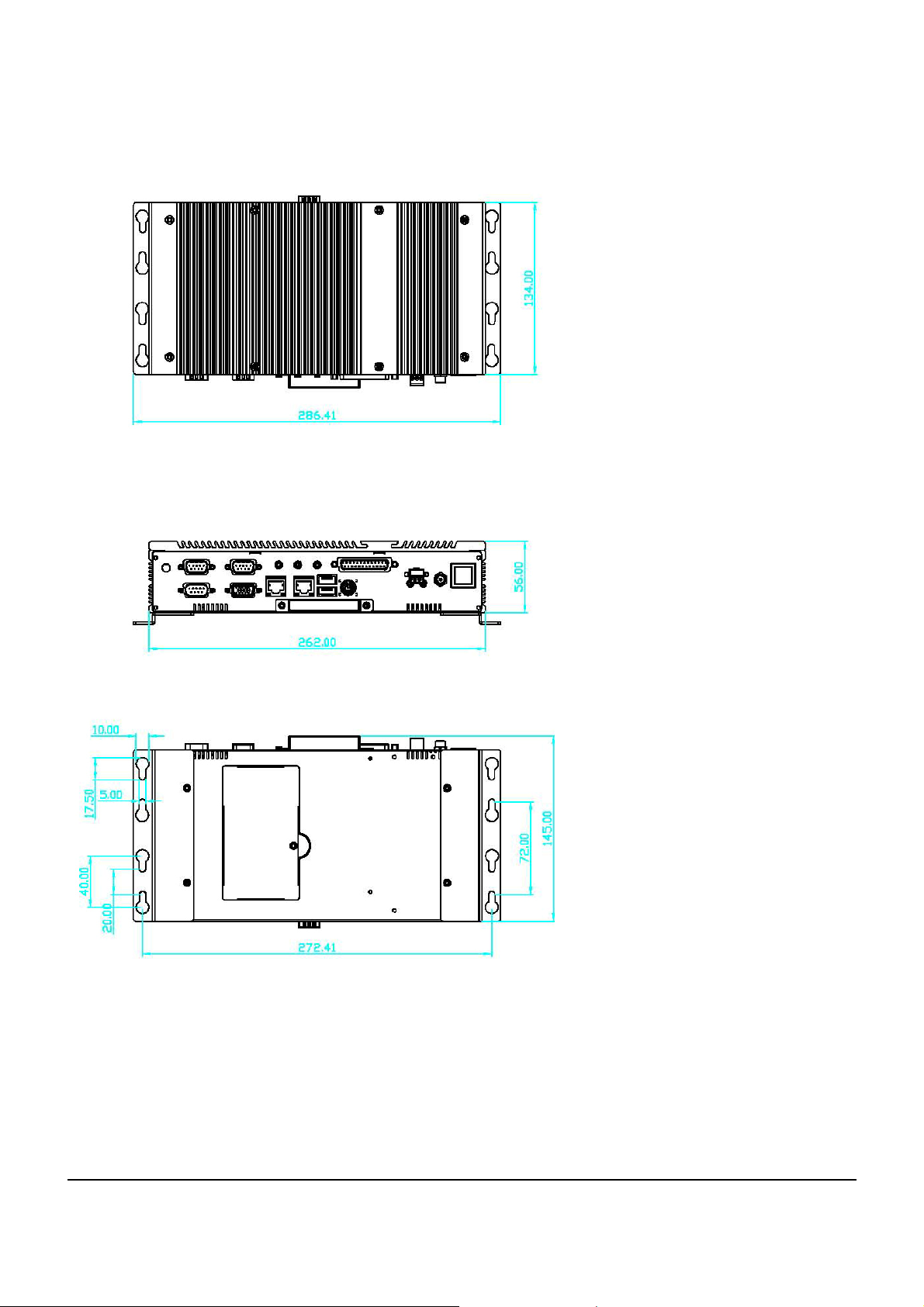
DIMENSION DRAWING
The dimensions of the EBC-2102/2102W chassis are shown below.
Figure 1: Dimension Drawing
EBC-2102/2102W QIG IEI Technology Corp. Page 2
Page 3

INSTALLATION STEPS
To install the EBC-2102/2102W chassis, the following installation
steps must be completed:
Step 1: Unpack the chassis.
Step 2: Remove the top cover.
Step 3: Install the internal 2.5” HDD.
Step 4: Install the system fan. (optional)
Step 5: Install the Wi-Fi module. (optional)
Step 6: Install the SBC (Single Board Computer).
Step 7: Connect the cables.
Step 8: Reinstall the top cover.
Step 9: Install a SO-DIMM.
Step 10: Mount the chassis. (optional)
The installation steps outlined above are described in detail below.
Please refer to the relevant section.
STEP 3: DISK DRIVE INSTALLATION
The EBC-2102/2102W chassis has the capacity for one 2.5” internal
HDD. To install the HDD, please follow the steps below.
Step 1: Remove the four HDD bracket retention screws.
Figure 3: HDD Bracket Retention Screws
STEP 1: UNPACK
The EBC-2102/2102W is shipped in a plastic bag that is placed
inside a cardboard box. The items are also shipped with the chassis.
When unpacking the chassis please:
Make sure all the items listed in the PACKING LIST
section are present.
Make sure the chassis has not been damaged in any
way.
STEP 2: REMOVE THE TOP COVER
The top cover is secured to the chassis with eight retention
screws. To remove the top cover, follow the steps below.
Step 1: Remove the eight top cover retention screws on
the chassis.
Step 2: Lift the HDD bracket out of the chassis and put it
on a flat surface.
Step 3: Attach the HDD to the HDD bracket. Secure the
HDD with the HDD bracket by four retention
screws (
Figure 4).
Figure 4: HDD Installation
Step 4: Connect the SATA cable to the rear of the HDD
Figure 4).
(
Step 5: Install the HDD and the bracket into the chassis
with four previously removed retention screws.
Step 6: Once the motherboard is installed to the chassis,
correctly connect the SATA signal and power
Figure 2: Top Cover Retention Screws
Step 2: Lift the cover up gently.
cables to the motherboard. Please refer to the
user manual that came with the motherboard for
the connector locations.
EBC-2102/2102W QIG IEI Technology Corp. Page 3
Page 4

STEP 4: SYSTEM FAN INSTALLATION
(OPTIONAL)
To install the optional system fan, please follow the steps
below.
Step 1: Attach the system fan to the chassis, aligning the
retention screw holes on the system fan with the
retention screw holes on the chassis (
Figure 5).
Figure 5: System Fan Installation
Step 2: Secure the system fan to the chassis by four
retention screws (
Figure 6).
Figure 7: Wi-Fi Module Installation
Step 4: Connect the Wi-Fi antenna cable from the
chassis to the Wi-Fi module.
Figure 6: System Fan Retention Screws
Step 3: Once the motherboard is installed to the chassis,
connect the system fan cable to the system fan
connector on the motherboard. Please refer to
the user manual that came with the motherboard
for the connector location.
STEP 5: WI-FI MODULE INSTALLATION
(OPTIONAL)
To install the optional Wi-Fi module, please follow the steps
below.
Step 1: Turn the motherboard over. Locate the PCIe Mini
card socket.
Step 2: Insert the Wi-Fi module into the PCIe Mini socket
at an angle. To do this, line up the notch on the
Wi-Fi module with the notch on the connector.
Slide the Wi-Fi module into the socket at an angle
of about 20º.
Figure 8: Wi-Fi Antenna Cable Connection
STEP 6: MOTHERBOARD
INSTALLATION
To install a NANO-PV series motherboard, please follow the
instructions below:
Step 1: Place the motherboard inside the chassis. Make
sure the external peripheral interface connectors
fit into the predrilled holes on the rear of the
chassis.
Step 2: Align the four retention screw holes on the
motherboard with the retention screw holes on
the bottom of the chassis.
Step 3: Install the motherboard to the chassis with four
retention screws.
Step 3: Push down until the card clips into place. Push
the other end of the card down until it clips into
place on the plastic connector.
Figure 9: Motherboard Retention Screws
EBC-2102/2102W QIG IEI Technology Corp. Page 4
Page 5

STEP 7: CABLING
There are power button with LED and ports on the front
panel and rear panel of the EBC-2102/2102W chassis.
They are:
o 1 x Power button with LED
o 1 x 12 V DC power input jack
o 1 x Parallel port connector
o 3 x Audio jacks (line-in, line-out, mic-in)
o 4 x USB ports
o 3 x RS-232 serial ports (DB-9)
These components are all connected to the motherboard
with cables. To correctly connect these cables, please refer
to the user manual that came with the motherboard. The
chassis cables and the corresponding on-board connectors
are listed below.
Chassis Cable Label Description
Power Button with
LED
Parallel Port
Connector
Audio Jacks AUDIO1 Audio connector
RS-232 Serial
Ports
USB Ports USB0_1
Power Input CPU12V1 12V power connector
F_PANEL1 Front panel connector
LPT1 Parallel port connector
COM2
COM3
COM4
USB4_5
Serial port connectors
USB connectors
Step 4: Gently push downwards and the arms clip into
place.
Figure 11: SO-DIMM Installation
Step 5: Reinstall the SO-DIMM access panel.
STEP 9: WALL-MOUNT PLATES
INSTALLATION
Two wall-mount plates are shipped with the EBC-2102/2102W
chassis. The wall-mount plates are installed on the sides, at the
bottom of the chassis. Each plate is secured to the chassis by two
retention screws. To install the wall-mount plates, please follow the
steps below.
Step 1: Align the retention screw holes in the wall-mount
plate with the retention screw holes on the side of
the chassis.
Table 2: Cables and Connectors
STEP 8: SO-DIMM INSTALLATION
To install the SO-DIMM, please follow the steps below.
Step 1: Locate the SO-DIMM access panel on the
bottom of the chassis. Remove the retention
screw and remove the panel.
Figure 10: SO-DIMM Access Panel Retention Screw
Step 2: Insert two retention screws for each wall-mount
plate.
Figure 12: Wall-mount Plate Retention Screws
Step 2: Locate the SO-DIMM socket on the motherboard.
Step 3: Align the notch on the memory with the notch on
the memory socket. Push the memory in at a 20º
angle.
EBC-2102/2102W QIG IEI Technology Corp. Page 5
 Loading...