

Page 1
EBC-2100
IEI Technology Corp.
EBC-2100
EPIC-NANO Series Embedded Board Chassis
Quick Installation Guide
Version 1.1 January 24, 2006
Packing Content
A.
Chassis x 1 pcs B. QIG C. Screws
D.
Wall Mounting Kits E. Rubber Foot Pad F. Power Adapter with Power Cord
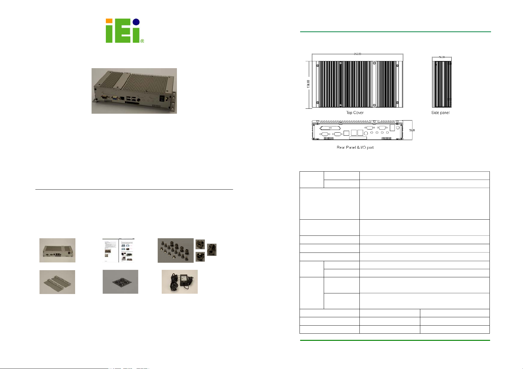
Product Dimensions
Product Specification
Cover/Base AL 3.2mm / 1.0mm Material &
Thickness
Support IEI EPIC-NANO
Embedded Board
I/O Interface COM x(1 + 2), VGAx1, LANx1, CFx1, PS/2x1, USBx4,
Internal Drive Bay 2.5” HDD
Color Pantone Gray 7C
Expansion Slots Support PC/104 or PC/104+ module space
Vibration
Chassis Dimension D134xW262xH56 mm D5.27”xW10.3”xH2.2”
Net Weight / Gross Weight 1 / 3 (kg) 2.1 / 6.3 (lb)
CFM / CUFT 2.986CFM 0.6329cuft
Brackets SECC 2.0mm
NANO-7240 series
NANO-7270G series
NANO-7270-600 series
NANO-7270-PM733 series
Audiox4, LPTx1, Power Switchx1, Power Jack x 1
Operating 3G acceleration peak to peak (11ms) Shock
Non-Operating 10G acceleration peak to peak (11ms)
Operating 10~57Hz, 0.006” double amplitude displacement
57~500Hz, 1.0G acceleration peak to peak
Non-operating 5~17Hz, 0.1” double amplitude displacement
17~640Hz, 1.5G acceleration peak to peak
IEI Technology Corp.
Page 2
Page 2
EBC-2100
Optional Peripherals
A.1 Optional Socket type CPU Heatsink Module (P/N: 34000-000060-RS)
AL+CU Heatsink with screws
A.2 Optional Cooling Fan Module (P/N: 19100-000027-RS)
40x40x10mm, +12V ball bearing Fan; 3 Pin; 6000RPM with screws
A.3 Optional IDE cable (P/N: 32200-000037-RS)
44pin IDE cable for 2.5” HDD
A.1 A.2 A.3
Recommendation of System cooling Components
□ recommended ■ must-have
Board Model Code CPU Board Companion
Heatsink
NANO-7240-400
-R10
NANO-7270G-R11 Socket 479 base
NANO-7270-600-R11
NANO-7270-600Z-R11
ULV Intel Celeron
400MHz
Pentium M/ Celero n M
CPU up to 1.8GHz
ULV Intel Celeron M
600MHz ■
#1
■
■
#1 Operation Temperature: 0℃~ 40℃
Installing NANO-7270G-R11 with Pentium M 2.0GHz CPU into
EBC-2100 is not recommended due to thermal issue.
Heatsink
34000-000060-RS
■ ■
System fan
19100-000027-RS
□
□
IEI Technology Corp.
Hardware Installation
The following procedures demonstrate the installation of EBC-2100. Please read
the precautions carefully before installing it.
Precautions
1. Always disconnect the unit from the power outlet whenever installing
or fixing a component inside the chassis.
2. If possible, always wear a grounded wrist strap when installing or
fixing a component inside the chassis.
3. Hold electronic circuit boards (EPIC-NANO board) by the edges only.
Do not touch the components on the board unless it is necessary.
4. Use the correct screws and never overly tighten them.
5. Keep the whole set original package in case the unit has to be
returned.
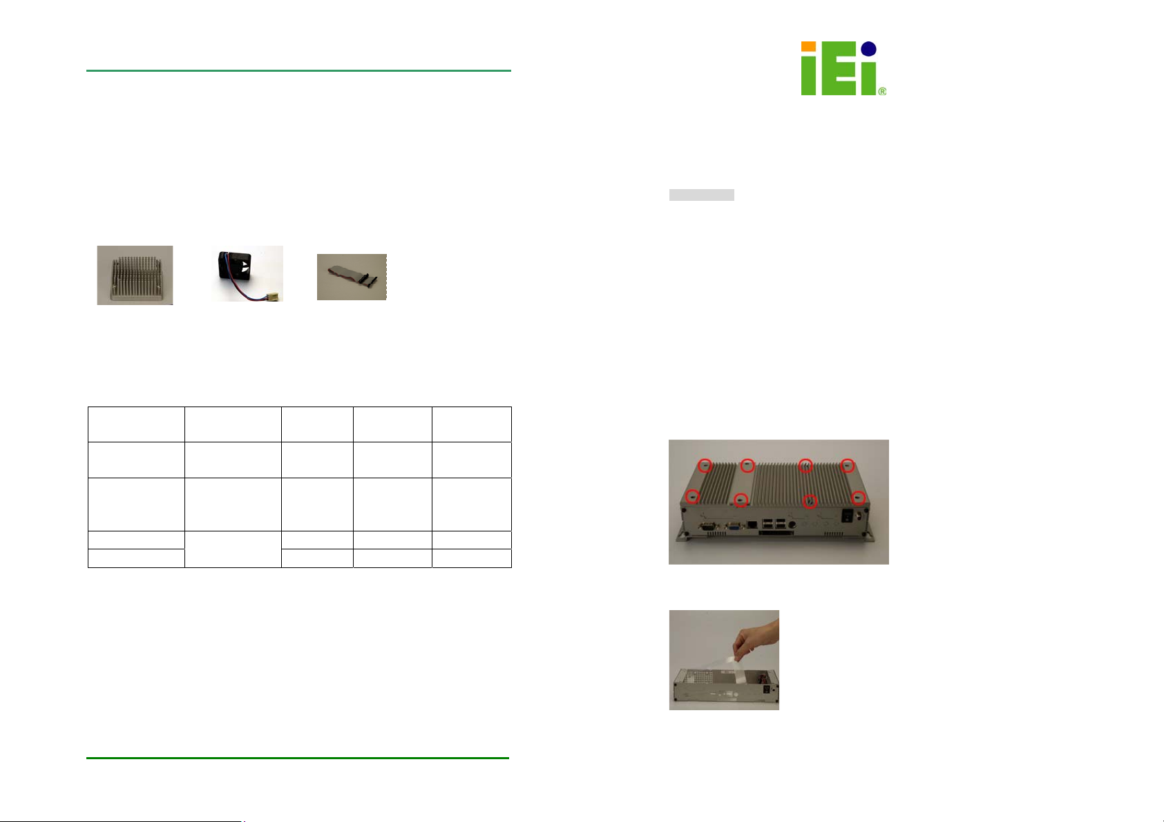
Step 1
Remove eight screws from the cover by screwdrivers.
Step 2
Remove the plastic shield inside the chassis.
Step 3
IEI Technology Corp.
Page 3
Page 3

EBC-2100
If additional hard drive storage is required, simply remove the HDD bracket from the chassis.
Then connect the hard drive to the HDD bracket, plug the HDD cable to the hard drive, and
assemble the HDD bracket with HDD back into the chassis. The connector of the hard drive
should be at the opposite side of the power switch after installation.
Step 4
An optional 40mm cooling fan can accommodate in EBC-2100. The arrow sign on the
cooling fan indicates the direction of airflow and it should point outside the chassis.
HDD bracket
Power switch
EBC-2100
Step 5
Before installing CPU board into the chassis, CPU, Memory, heatsink and CPU cooling fan
must be secured properly onto the CPU board. To prevent heatsink deformation, please
handle the heatsink diagonally.
Step 6
Unscrew the COM port/VGA port with proper tool.
IEI Technology Corp.
Page 5
Step 7
Align the motherboard with the chassis standoffs, secure with screws for motherboard and
COM port and VGA port.
Step 8
Align the power cable into the embedded board.
IEI Technology Corp.
Page 6
Page 4

EBC-2100
EBC-2100
Contact Information
Step 9
Place the cover back on the top of the case and secure with screws.
Step 10
If wall mounting is required, secure the wall mounting kits to the bottom of the chassis with
screws. For desktop usage please apply the rubber foot pads to the bottom of the chassis.
Step 11
When replacing the system memory, simply remove the screws on the bottom cover then
insert the memory to the memory slot. Then place the cover back on the chassis and secure
with screws.
IEI Technology Corp.
TEL : 886-2-86916798
FAX : 886-2-66160029
Email: sales@iei.com.tw
Website:http://www.ieiworld.com
Address: No. 29, Jhongsing Rd.,Sijhih City,Taipei County, 221, Taiwan
IEI Technology Corp.
Page 7
IEI Technology Corp.
Page 8
 Loading...