

IEI Integration CV-D25502, CV-N26002 User Manual
NANO-CV-D25502/N26002 EPIC SBC
IEI Technology Corp.
MODEL:
NANO-CV-D25502/N26002
EPIC SBC with Intel® Atom™ D2550/N2600 Processor,
DDR3, Dual VGA, LVDS, Dual PCIe GbE, USB 2.0,
Dual PCIe Mini, SATA 3Gb/s, Audio and RoHS
User Manual
Rev. 1.00 – 27 August, 2012
Page i
NANO-CV-D25502/N26002 EPIC SBC
Revision
Date Version Changes
27 August, 2012
1.00 Initial release
Page ii

NANO-CV-D25502/N26002 EPIC SBC
COPYRIGHT NOTICE
The information in this document is subject to change without prior notice in order to
improve reliability, design and function and does not represent a commitment on the part
of the manufacturer.
In no event will the manufacturer be liable for direct, indirect, special, incidental, or
consequential damages arising out of the use or inability to use the product or
documentation, even if advised of the possibility of such damages.
This document contains proprietary information protected by copyright. All rights are
Copyright
reserved. No part of this manual may be reproduced by any mechanical, electronic, or
other means in any form without prior written permission of the manufacturer.
TRADEMARKS
All registered trademarks and product names mentioned herein are used for identification
purposes only and may be trademarks and/or registered trademarks of their respective
owners.
Page iii

NANO-CV-D25502/N26002 EPIC SBC
Table of Contents
1 INTRODUCTION.......................................................................................................... 1
1.1 INTRODUCTION........................................................................................................... 2
1.2 MODEL VARIATIONS ................................................................................................... 2
1.3 FEATURES................................................................................................................... 2
1.4 CONNECTORS ............................................................................................................. 3
1.5 DIMENSIONS............................................................................................................... 4
1.6 DATA FLOW................................................................................................................ 5
1.7 TECHNICAL SPECIFICATIONS ...................................................................................... 6
2 PACKING LIST.............................................................................................................8
2.1 ANTI-STATIC PRECAUTIONS........................................................................................ 9
2.2 UNPACKING PRECAUTIONS......................................................................................... 9
2.3 PACKING LIST........................................................................................................... 10
2.4 OPTIONAL ITEMS.......................................................................................................11
3 CONNECTORS ........................................................................................................... 12
3.1 PERIPHERAL INTERFACE CONNECTORS..................................................................... 13
3.1.1 NANO-CV-D25502/N26002 Layout................................................................. 13
3.1.2 Peripheral Interface Connectors ..................................................................... 13
3.1.3 External Interface Panel Connectors............................................................... 14
3.2 INTERNAL PERIPHERAL CONNECTORS...................................................................... 15
3.2.1 5 V SATA Power Connectors............................................................................ 15
3.2.2 Audio Connector .............................................................................................. 15
3.2.3 Backlight Inverter Connector .......................................................................... 16
3.2.4 Battery Connector............................................................................................ 17
3.2.5 Digital Input/Output (DIO) Connector............................................................ 18
3.2.6 Fan Connectors................................................................................................ 19
3.2.7 Front Panel Connector.................................................................................... 20
3.2.8 Keyboard/Mouse Connector............................................................................ 20
3.2.9 LVDS1 Connector............................................................................................ 21
3.2.10 PCIe Mini Card Slots..................................................................................... 22
Page iv

NANO-CV-D25502/N26002 EPIC SBC
3.2.11 Power Connector (9V~28V)........................................................................... 24
3.2.12 RS-232 Serial Port Connectors...................................................................... 25
3.2.13 RS-422/485 Serial Port Connector................................................................ 26
3.2.14 SATA Drive Connectors ................................................................................. 27
3.2.15 SO-DIMM Connector..................................................................................... 28
3.2.16 USB Connector .............................................................................................. 28
3.3 EXTERNAL PERIPHERAL INTERFACE CONNECTOR PANEL ......................................... 29
3.3.1 Ethernet Connectors ........................................................................................ 29
3.3.2 USB Connectors............................................................................................... 30
3.3.3 VGA Connectors .............................................................................................. 31
4 INSTALLATION ......................................................................................................... 32
4.1 ANTI-STATIC PRECAUTIONS...................................................................................... 33
4.2 INSTALLATION CONSIDERATIONS.............................................................................. 33
4.3 SO-DIMM INSTALLATION ....................................................................................... 35
4.4 JUMPER SETTINGS .................................................................................................... 36
4.4.1 AT/ATX Power Selection Jumper..................................................................... 36
4.4.2 Clear CMOS Jumper........................................................................................ 37
4.4.3 LVDS1 Voltage Selection.................................................................................. 38
4.4.4 mSATA/PCIe Mini Selection ............................................................................ 39
4.5 CHASSIS INSTALLATION............................................................................................ 40
4.5.1 Airflow.............................................................................................................. 40
4.5.2 Motherboard Installation................................................................................. 40
4.6 INTERNAL PERIPHERAL DEVICE CONNECTIONS........................................................ 40
4.6.1 AT/ATX Power Connection.............................................................................. 41
4.6.2 Audio Kit Installation....................................................................................... 42
4.6.3 LVDS LCD Installation.................................................................................... 43
4.6.4 PCIe Mini Card Installation............................................................................ 46
4.6.5 SATA Drive Connection ................................................................................... 47
4.6.6 Single RS-232 Cable........................................................................................ 48
4.7 EXTERNAL PERIPHERAL INTERFACE CONNECTION ................................................... 49
4.7.1 LAN Connection............................................................................................... 49
4.7.2 USB Connection (Dual Connector)................................................................. 50
4.7.3 VGA Monitor Connection ................................................................................ 51
4.8 HEAT SINK ENCLOSURE............................................................................................ 52
Page v

5 BIOS.............................................................................................................................. 54
5.1 INTRODUCTION......................................................................................................... 55
5.1.1 Starting Setup................................................................................................... 55
5.1.2 Using Setup...................................................................................................... 55
5.1.3 Getting Help..................................................................................................... 56
5.1.4 Unable to Reboot after Configuration Changes.............................................. 56
5.1.5 BIOS Menu Bar................................................................................................ 56
5.2 MAIN........................................................................................................................ 57
5.3 ADVANCED ............................................................................................................... 58
5.3.1 ACPI Settings................................................................................................... 58
5.3.2 RTC Wake Settings........................................................................................... 59
5.3.3 CPU Configuration.......................................................................................... 61
5.3.4 IDE Configuration........................................................................................... 62
5.3.5 USB Configuration........................................................................................... 63
NANO-CV-D25502/N26002 EPIC SBC
5.3.6 F81866 Super IO Configuration...................................................................... 64
5.3.6.1 Serial Port n Configuration....................................................................... 65
5.3.7 F81866 H/W Monitor....................................................................................... 69
5.3.7.1 Smart Fan Mode Configuration................................................................ 70
5.3.8 Serial Port Console Redirection...................................................................... 71
5.3.9 iEi Feature....................................................................................................... 73
5.4 CHIPSET ................................................................................................................... 74
5.4.1 Host Bridge Configuration .............................................................................. 74
5.4.1.1 Intel IGD Configuration............................................................................ 75
5.4.2 South Bridge Configuration............................................................................. 77
5.5 BOOT........................................................................................................................ 78
5.6 SECURITY................................................................................................................. 80
5.7 SAVE & EXIT............................................................................................................ 80
6 SOFTWARE DRIVERS.............................................................................................. 82
6.1 AVAILABLE SOFTWARE DRIVERS .............................................................................. 83
6.2 ST ARTING THE DRIVER PROGRAM ............................................................................ 83
6.3 CHIPSET DRIVER INSTALLATION............................................................................... 85
6.4 VGA DRIVER INSTALLATION.................................................................................... 89
6.5 LAN DRIVER INSTALLATION.................................................................................... 93
6.6 AUDIO DRIVER INSTALLATION ................................................................................. 96
Page vi

NANO-CV-D25502/N26002 EPIC SBC
A BIOS OPTIONS ........................................................................................................ 100
B ONE KEY RECOVERY........................................................................................... 103
B.1 ONE KEY RECOVERY INTRODUCTION .................................................................... 104
B.1.1 System Requirement....................................................................................... 105
B.1.2 Supported Operating System......................................................................... 106
B.2 SETUP PROCEDURE FOR WINDOWS........................................................................ 107
B.2.1 Hardware and BIOS Setup ............................................................................ 108
B.2.2 Create Partitions........................................................................................... 108
B.2.3 Install Operating System, Drivers and Applications......................................112
B.2.4 Build-up Recovery Partition...........................................................................113
B.2.5 Create Factory Default Image........................................................................115
B.3 AUTO RECOVERY SETUP PROCEDURE.................................................................... 120
B.4 SETUP PROCEDURE FOR LINUX.............................................................................. 125
B.5 RECOVERY TOOL FUNCTIONS ................................................................................ 128
B.5.1 Factory Restore............................................................................................. 130
B.5.2 Backup System............................................................................................... 131
B.5.3 Restore Your Last Backup.............................................................................. 132
B.5.4 Manual........................................................................................................... 133
B.6 RESTORE SYSTEMS FROM A LINUX SERVER THROUGH LAN.................................. 134
B.6.1 Configure DHCP Server Settings.................................................................. 135
B.6.2 Configure TFTP Settings ............................................................................... 136
B.6.3 Configure One Key Recovery Server Settings............................................... 137
B.6.4 Start the DHCP, TFTP and HTTP................................................................. 138
B.6.5 Create Shared Directory................................................................................ 138
B.6.6 Setup a Client System for Auto Recovery...................................................... 139
B.7 OTHER INFORMATION ............................................................................................ 142
B.7.1 Using AHCI Mode or ALi M5283 / VIA VT6421A Controller....................... 142
B.7.2 System Memory Requirement ........................................................................ 144
C TERMINOLOGY ..................................................................................................... 145
D DIGITAL I/O INTERFACE..................................................................................... 149
D.1 INTRODUCTION...................................................................................................... 150
D.2 DIO CONNECTOR PINOUTS ................................................................................... 150
D.3 ASSEMBLY LANGUAGE SAMPLES........................................................................... 151
Page vii

D.3.1 Enable the DIO Input Function .................................................................... 151
D.3.2 Enable the DIO Output Function.................................................................. 151
E WA TCHDOG TIMER............................................................................................... 152
F HAZARDOUS MATERIALS DISCLOSURE........................................................ 155
F.1 HAZARDOUS MATERIALS DISCLOSURE TABLE FOR IPB PRODUCTS CERTIFIED AS
ROHS COMPLIANT UNDER 2002/95/EC WITHOUT MERCURY..................................... 156
NANO-CV-D25502/N26002 EPIC SBC
Page viii

NANO-CV-D25502/N26002 EPIC SBC
List of Figures
Figure 1-1: NANO-CV-D25502/N26002..........................................................................................2
Figure 1-2: Connectors ..................................................................................................................3
Figure 1-3: NANO-CV-D25502/N26002 Dimensions (mm)...........................................................4
Figure 1-4: External Interface Panel Dimensions (mm)..............................................................4
Figure 1-5: Data Flow Diagram......................................................................................................5
Figure 3-1: Connectors and Jumpers.........................................................................................13
Figure 3-2: 5 V SATA Power Connector Locations...................................................................15
Figure 3-3: Audio Connector Location.......................................................................................16
Figure 3-4: Backlight Inverter Connector Location...................................................................17
Figure 3-5: Battery Connector Location.....................................................................................18
Figure 3-6: Digital I/O Connector Location ................................................................................18
Figure 3-7: Fan Connector Locations.........................................................................................19
Figure 3-8: Front Panel Connector Location .............................................................................20
Figure 3-9: Keyboard/Mouse Connector Location....................................................................21
Figure 3-10: LVDS1 Connector Location ...................................................................................22
Figure 3-11: PCIe Mini Card Slot Locations...............................................................................23
Figure 3-12: Power Connector Location ....................................................................................24
Figure 3-13: RS-232 Serial Port Connector Locations..............................................................25
Figure 3-14: RS-422/485 Connector Location............................................................................26
Figure 3-15: SATA Drive Connector Locations.........................................................................27
Figure 3-16: SO-DIMM Connector Location...............................................................................28
Figure 3-17: USB Connector Location........................................................................................28
Figure 3-18: External Peripheral Interface Connector..............................................................29
Figure 3-19: RJ-45 Ethernet Connector......................................................................................30
Figure 3-20: VGA Connector .......................................................................................................31
Figure 4-1: SO-DIMM Installation................................................................................................35
Figure 4-2: AT/ATX Power Selection Jumper Location............................................................37
Figure 4-3: Clear CMOS Jumper Location .................................................................................38
Figure 4-4: LVDS1 Voltage Selection Jumper Location ...........................................................39
Figure 4-5: mSATA/PCIe Mini Mode Selection Jumper Location............................................39
Page ix

Figure 4-6: Power Cable to Motherboard Connection..............................................................41
Figure 4-7: Connect Power Cable to Power Supply..................................................................42
Figure 4-8: Audio Kit Cable Connection.....................................................................................43
Figure 4-9: LVDS Connector........................................................................................................44
Figure 4-10: Backlight Inverter Connection...............................................................................45
Figure 4-11: PCIe Mini Card Installation.....................................................................................46
Figure 4-12: SATA Drive Cable Connection...............................................................................47
Figure 4-13: Single RS-232 Cable Installation ...........................................................................48
Figure 4-14: LAN Connection......................................................................................................49
Figure 4-15: USB Connector........................................................................................................50
Figure 4-16: VGA Connector .......................................................................................................51
Figure 4-17: Heat Sink Retention Screws ..................................................................................53
Figure 6-1: Start Up Screen .........................................................................................................84
Figure 6-2: Drivers........................................................................................................................84
NANO-CV-D25502/N26002 EPIC SBC
Figure 6-3: Chipset Driver Screen...............................................................................................85
Figure 6-4: Chipset Driver Welcome Screen..............................................................................86
Figure 6-5: Chipset Driver License Agreement.........................................................................87
Figure 6-6: Chipset Driver Read Me File ....................................................................................87
Figure 6-7: Chipset Driver Setup Operations ............................................................................88
Figure 6-8: Chipset Driver Installation Finish Screen...............................................................89
Figure 6-9: VGA Driver Welcome Screen...................................................................................90
Figure 6-10: VGA Driver License Agreement.............................................................................91
Figure 6-11: VGA Driver Read Me File........................................................................................91
Figure 6-12: VGA Driver Setup Operations................................................................................92
Figure 6-13: VGA Driver Installation Finish Screen..................................................................93
Figure 6-14: LAN Driver Welcome Screen .................................................................................94
Figure 6-15: LAN Driver Installation ...........................................................................................95
Figure 6-16: LAN Driver Installation Complete..........................................................................96
Figure 6-17: Audio Driver Installation File Extraction...............................................................97
Figure 6-18: Audio Driver Welcome Screen...............................................................................97
Figure 6-19: Audio Driver Installation.........................................................................................98
Figure 6-20: Audio Driver Installation Complete.......................................................................98
Figure B-1: IEI One Key Recovery Tool Menu........................................................................ 104
Figure B-2: Launching the Recovery Tool.............................................................................. 109
Figure B-3: Recovery Tool Setup Menu .................................................................................. 109
Page x

NANO-CV-D25502/N26002 EPIC SBC
Figure B-4: Command Prompt ................................................................................................. 110
Figure B-5: Partition Creation Commands.............................................................................. 111
Figure B-6: Launching the Recovery Tool.............................................................................. 113
Figure B-7: Manual Recovery Environment for Windows..................................................... 113
Figure B-8: Building the Recovery Partition........................................................................... 114
Figure B-9: Press Any Key to Continue.................................................................................. 114
Figure B-10: Press F3 to Boot into Recovery Mode............................................................... 115
Figure B-11: Recovery Tool Menu ........................................................................................... 115
Figure B-12: About Symantec Ghost Window........................................................................ 116
Figure B-13: Symantec Ghost Path ......................................................................................... 116
Figure B-14: Select a Local Source Drive ............................................................................... 117
Figure B-15: Select a Source Partition from Basic Drive ...................................................... 117
Figure B-16: File Name to Copy Image to ............................................................................... 118
Figure B-17: Compress Image.................................................................................................. 118
Figure B-18: Image Creation Confirmation............................................................................. 119
Figure B-19: Image Creation Complete................................................................................... 119
Figure B-20: Image Creation Complete................................................................................... 119
Figure B-21: Press Any Key to Continue................................................................................ 120
Figure B-22: Auto Recovery Utility.......................................................................................... 121
Figure B-23: Disable Automatically Restart............................................................................ 121
Figure B-24: Launching the Recovery Tool............................................................................ 122
Figure B-25: Auto Recovery Environment for Windows ....................................................... 122
Figure B-26: Building the Auto Recovery Partition................................................................ 123
Figure B-27: Factory Default Image Confirmation ................................................................. 123
Figure B-28: Image Creation Complete................................................................................... 124
Figure B-29: Press any key to continue.................................................................................. 124
Figure B-30: IEI Feature ............................................................................................................ 125
Figure B-31: Partitions for Linux.............................................................................................. 126
Figure B-32: System Configuration for Linux......................................................................... 127
Figure B-33: Access menu.lst in Linux (Text Mode).............................................................. 127
Figure B-34: Recovery Tool Menu ........................................................................................... 128
Figure B-35: Recovery Tool Main Menu.................................................................................. 129
Figure B-36: Restore Factory Default...................................................................................... 130
Figure B-37: Recovery Complete Window.............................................................................. 130
Figure B-38: Backup System.................................................................................................... 131
Page xi

Figure B-39: System Backup Complete Window ................................................................... 131
Figure B-40: Restore Backup................................................................................................... 132
Figure B-41: Restore System Backup Complete Window..................................................... 132
Figure B-42: Symantec Ghost Window ................................................................................... 133
Figure B-43: Disable Automatically Restart............................................................................ 140
NANO-CV-D25502/N26002 EPIC SBC
Page xii

NANO-CV-D25502/N26002 EPIC SBC
List of Tables
Table 1-1: NANO-CV-D25502/N26002 Model Variations..............................................................2
Table 1-2: NANO-CV-D25502/N26002 Specifications..................................................................7
Table 2-1: Packing List.................................................................................................................11
Table 2-2: Optional Items.............................................................................................................11
Table 3-1: Peripheral Interface Connectors...............................................................................14
Table 3-2: Rear Panel Connectors..............................................................................................14
Table 3-3: 5 V SATA Power Connector Pinouts ........................................................................15
Table 3-4: Audio Connector Pinouts ..........................................................................................16
Table 3-5: Backlight Inverter Connector Pinouts......................................................................17
Table 3-6: Battery Connector Pinouts........................................................................................18
Table 3-7: Digital I/O Connector Pinouts....................................................................................19
Table 3-8: Fan Connector Pinouts..............................................................................................19
Table 3-9: Front Panel Connector Pinouts.................................................................................20
Table 3-10: Keyboard/Mouse Connector Pinouts .....................................................................21
Table 3-11: LVDS1 Connector Pinouts.......................................................................................22
Table 3-12: PCIe Mini Card Slot Pinouts ....................................................................................24
Table 3-13: Power Connector Pinouts........................................................................................25
Table 3-14: RS-232 Serial Port Connector Pinouts...................................................................25
Table 3-15: RS-422/485 Connector Pinouts...............................................................................26
Table 3-16: SATA Drive Connector Pinouts...............................................................................27
Table 3-17: USB Connector Pinouts...........................................................................................29
Table 3-18: LAN Pinouts ..............................................................................................................30
Table 3-19: RJ-45 Ethernet Connector LEDs.............................................................................30
Table 3-20: USB Port Pinouts......................................................................................................30
Table 3-21: VGA Connector Pinouts...........................................................................................31
Table 4-1: Jumpers.......................................................................................................................36
Table 4-2: AT/ATX Power Selection Jumper Settings...............................................................37
Table 4-3: Clear CMOS Jumper Settings....................................................................................37
Table 4-4: LVDS1 Voltage Selection Jumper Settings..............................................................38
Table 4-5: mSATA/PCIe Mini Mode Selection Jumper Settings...............................................39
Page xiii

Table 5-1: BIOS Navigation Keys................................................................................................56
NANO-CV-D25502/N26002 EPIC SBC
Page xiv

NANO-CV-D25502/N26002 EPIC SBC
BIOS Menus
BIOS Menu 1: Main.......................................................................................................................57
BIOS Menu 2: Advanced..............................................................................................................58
BIOS Menu 3: ACPI Settings .......................................................................................................59
BIOS Menu 4: RTC Wake Settings..............................................................................................60
BIOS Menu 5: CPU Configuration...............................................................................................61
BIOS Menu 6: IDE Configuration.................................................................................................62
BIOS Menu 7: USB Configuration...............................................................................................63
BIOS Menu 8: Super IO Configuration........................................................................................64
BIOS Menu 9: Serial Port n Configuration Menu.......................................................................65
BIOS Menu 10: F81866 H/W Monitor...........................................................................................69
BIOS Menu 11: Smart Fan Mode Configuration ........................................................................70
BIOS Menu 12: Serial Port Console Redirection.......................................................................71
BIOS Menu 13: iEi Feature...........................................................................................................73
BIOS Menu 14: Chipset................................................................................................................74
BIOS Menu 15: Host Bridge Configuration................................................................................75
BIOS Menu 16: Intel IGD Configuration......................................................................................75
BIOS Menu 17: South Bridge Configuration..............................................................................77
BIOS Menu 18: Boot.....................................................................................................................78
BIOS Menu 19: Security...............................................................................................................80
BIOS Menu 20: Save & Exit..........................................................................................................81
NANO-CV-D25502/N26002
Page xv
NANO-CV-D25502/N26002 EPIC SBC
1 Introduction
Chapter
1
Page 1
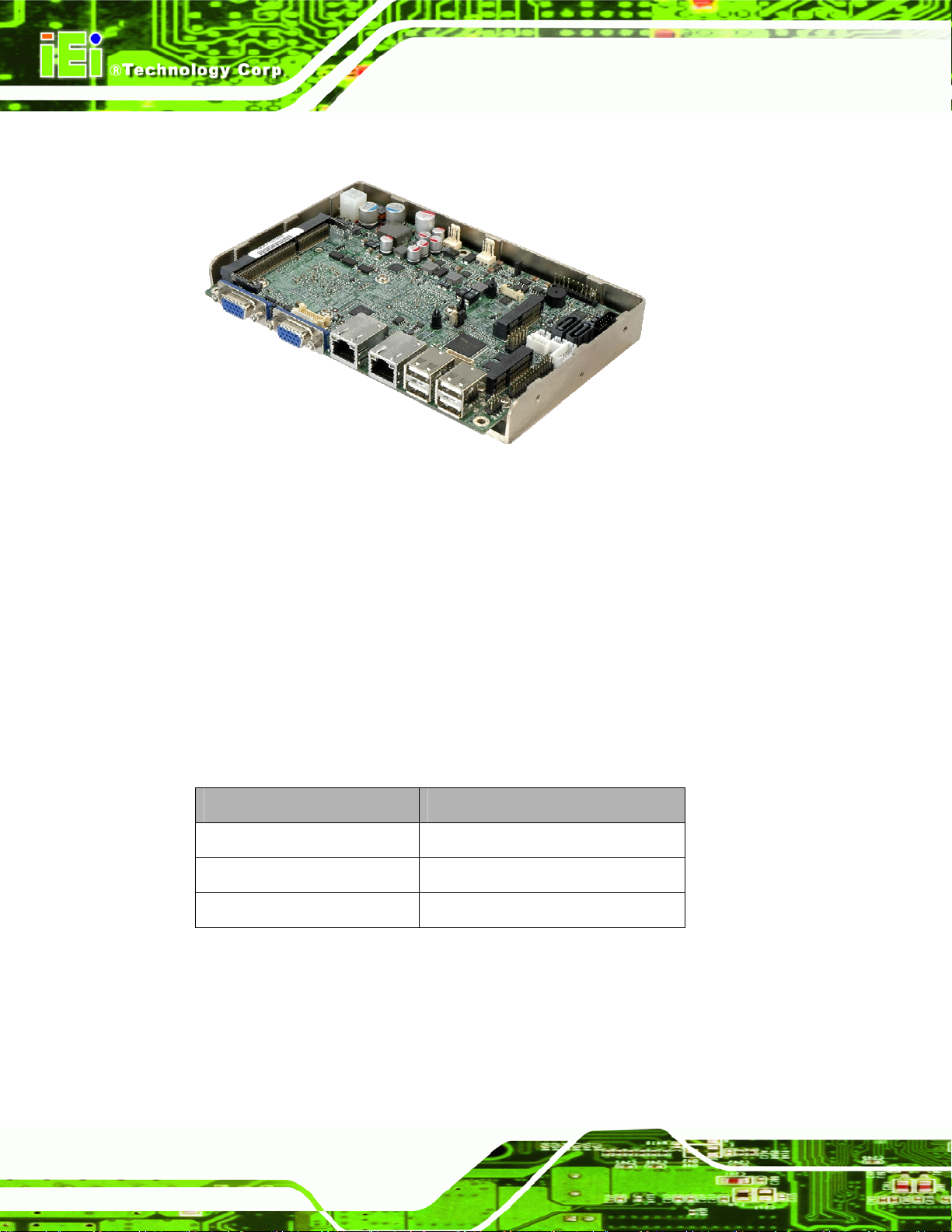
1.1 Introduction
Figure 1-1: NANO-CV-D25502/N26002
The NANO-CV-D25502/N26002 EPIC motherboard is an Intel® Atom™ D2550/N2600
NANO-CV-D25502/N26002 EPIC SBC
processor platform that supports one 1066 MHz or 800 MHz DDR3 SO-DIMM memory.
The NANO-CV-D25502/N26002 supports dual VGA display output and comes with a
LVDS connector supporting 24-bit or 18-bit LVDS screens. Maximum six USB ports, two
SATA 3Gb/s connectors, two PCIe Mini card slots, four COM ports, and one audio
connector provide flexible expansion options.
1.2 Model Variations
The model variations of the NANO-CV-D25502/N26002 are listed below.
Model No. CPU
NANO-CV-D25502-R10
NANO-CV-N26002-R10
NANO-CV-N28002-R10
Table 1-1: NANO-CV-D25502/N26002 Model Variations
1.3 Features
Intel® Atom D2550 1.86 GHz
Intel® Atom N2600 1.6 GHz
Intel® Atom N2800 1.86 GHz
Page 2
Some of the NANO-CV-D25502/N26002 motherboard features are listed below:
EPIC form factor
NANO-CV-D25502/N26002 EPIC SBC
Supports dual VGA and 18/24-bit LVDS interface for dual display
1066/800 MHz DDR3 SO-DIMM supports up to 4 GB
Easy-assembly thermal design by heat sink enclosure
Wide range power input (9V~28V)
Full-size PCIe Mini card slot with mSATA support
Dual GbE
RoHS compliant
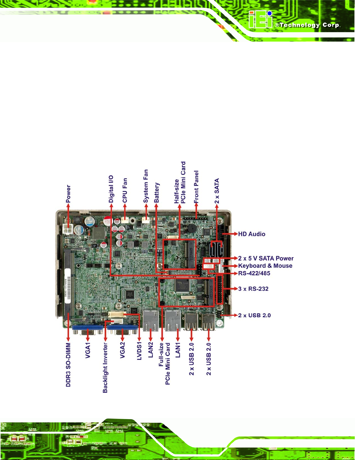
1.4 Connectors
The connectors on the NANO-CV-D25502/N26002 are sho wn in th e figure below.
Figure 1-2: Connectors
Page 3
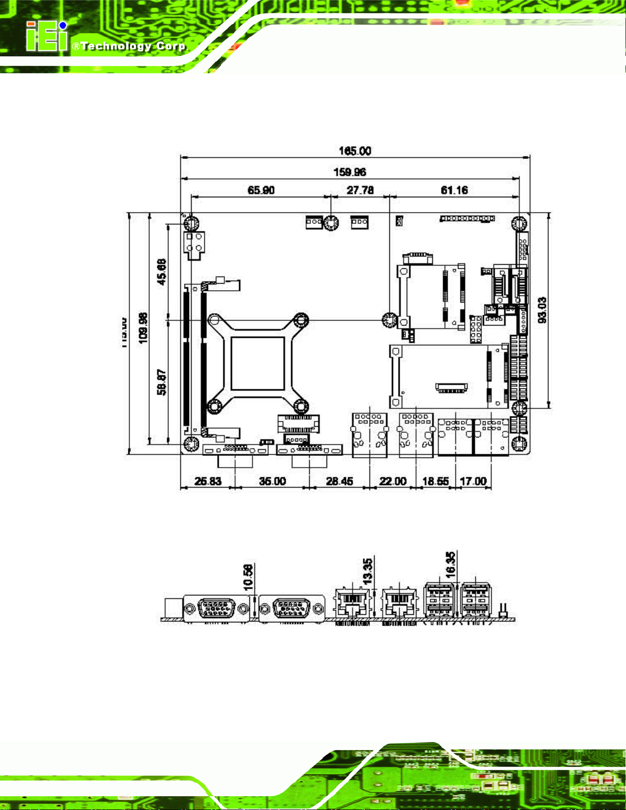
1.5 Dimensions
The main dimensions of the NANO-CV-D25502/N26002 are shown in the diagram below.
NANO-CV-D25502/N26002 EPIC SBC
Page 4
Figure 1-3: NANO-CV-D25502/N26002 Dimensions (mm)
.
Figure 1-4: External Interface Panel Dimensions (mm)
NANO-CV-D25502/N26002 EPIC SBC
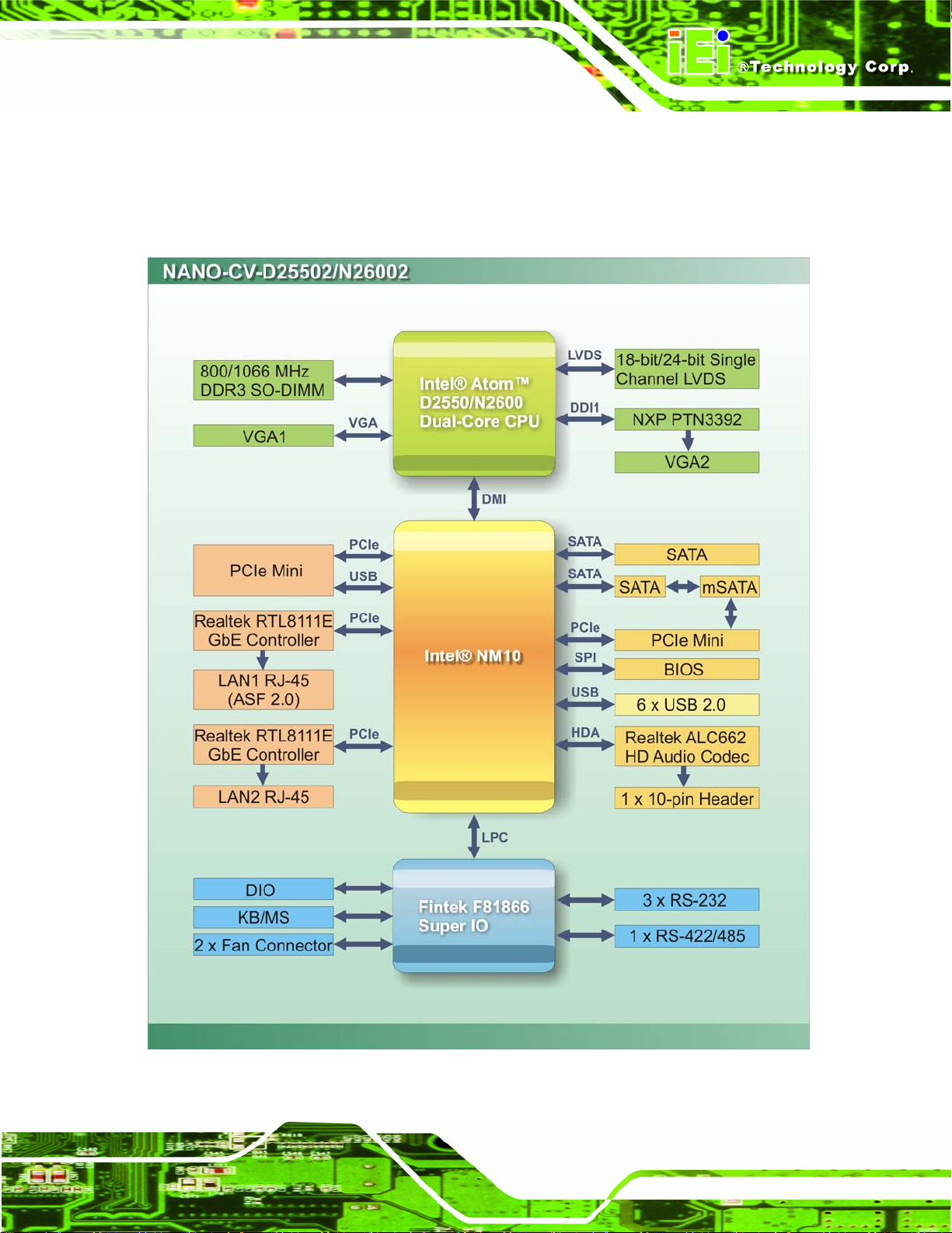
1.6 Data Flow
6Figure 1-5 shows the data flow between the system chipset, the CPU and other
components installed on the motherboard.
Figure 1-5: Data Flow Diagram
Page 5
NANO-CV-D25502/N26002 EPIC SBC
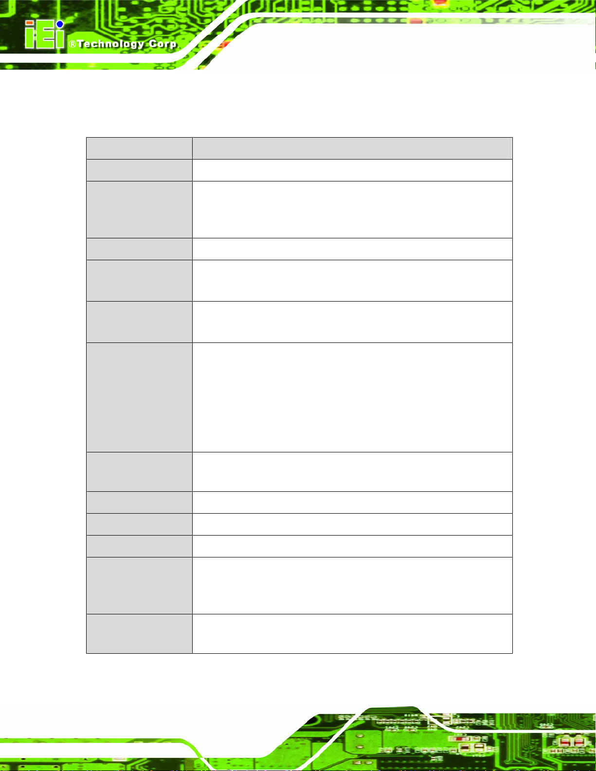
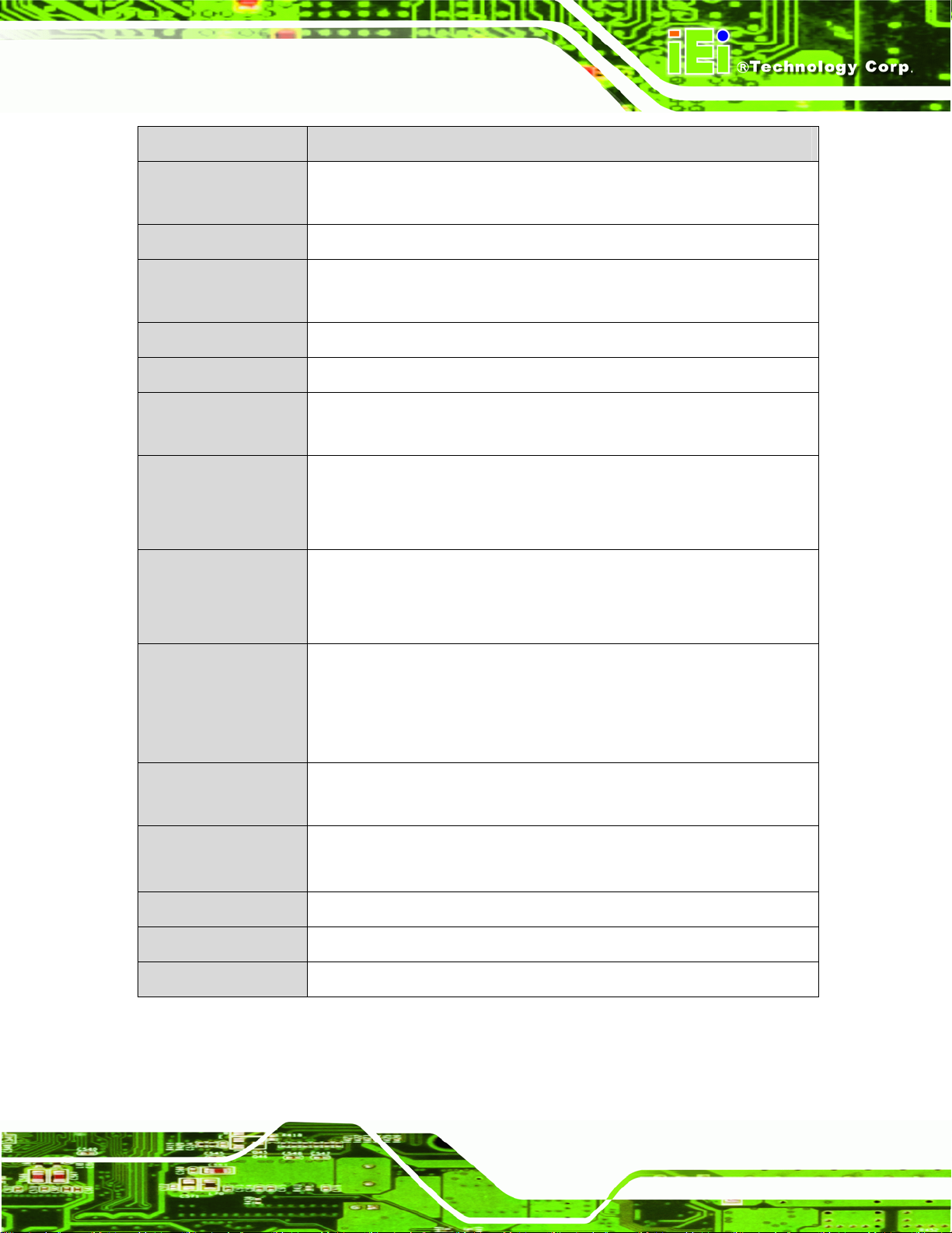
1.7 Technical Specifications
The NANO-CV-D25502/N26002 technical specifications are listed below.
Specification/Model NANO-CV-D25502/N26002
Form Factor
System CPU
System Chipset
Memory
Graphics Engine
Display
EPIC
1.86 GHz Intel® Atom™ D2550 dual-cor e CPU
1.6 GHz Intel® Atom™ N2600 dual-core CPU
1.86 GHz Intel® Atom™ N2800 dual-core CPU (optional)
Intel® NM10
D2550/N2800: One 1066 MHz DDR3 SO-DIMM support (up to 4 GB)
N2600: One 800 MHz DDR3 SO-DIMM support (up to 2 GB)
D2550/N2800: Intel® GMA 3650 with 640 MHz graphics core speed
N2600: Intel® GMA 3600 with 400 MHz graphics core speed
Dual display supported
First VGA is integrate d in the CPU (1920 x 1200)
Second VGA is driven by the NXP PTN3392 (1920 x 1200)
One LVDS is integrated in the CPU:
D2550: 24-bit single-channel LVDS up to 1440 x 900
N2600/N2800: 18-bit single-channel LVDS up to 1366 x 768
Ethernet
BIOS
Super I/O Controller
Watchdog Timer
Expansion
Audio
Page 6
Two Realtek RTL8111E PCIe GbE controllers
(LAN1 with ASF 2.0 support)
UEFI BIOS
Fintek F81866
Software programmable supports 1~2 55 sec. system reset
One full-size PCIe Mini card slot with mSATA support (SATA1 and
mSATA share SATA sign al)
One half-size PCIe Mini card slot
Realtek ALC662 HD Audio codec
One internal audio connector (10-pin box header)
NANO-CV-D25502/N26002 EPIC SBC
Specification/Model NANO-CV-D25502/N26002
COM
Digital I/O
Fan
Front Panel
Keyboard/Mouse
SATA
USB
Power Supply
Three RS-232
One RS-422/485
One 8-bit digital input/output connector (4-bit input/4-bit output)
One 3-pin CPU fan connector
One 3-pin system fan connector
One 10-pin header (power LED, HDD LED, power button, reset button)
One internal 6-pin wafer connector
Two SATA 3Gb/s ports with 5V power connectors (SATA1 and mSATA
share SATA signal)
Six USB 2.0/1.1 devices supported:
Four by external connectors
Two by on-board pin header
9V~28V
AT and ATX support
One internal 4-pin (2x2) power connector
12V @ 1.59 A (1.86 GHz Intel® Atom™ D2550 CPU with 4 GB 1333
Power Consumption
Operating
Temperature
Storage Temperature
Humidity (Operating)
Dimensions
Weight (GW/NW)
Table 1-2: NANO-CV-D25502/N26002 Specifications
MHz DDR3 SO-DIMM)
12V @ 1.23 A (1.6 GHz Intel® Atom™ N2600 CPU with 4 GB 1333 MHz
DDR3 SO-DIMM)
D2550: -20ºC ~ 60ºC with free air; -20ºC ~ 70ºC with force air
N2600/N2800: -20ºC ~ 70ºC with free air; -20ºC ~ 75ºC with force air
D2550: -30ºC ~ 80ºC
N2600/N2800: -30ºC ~ 85ºC
5% ~ 95% (non-condensing)
115 mm x 165 mm
850 g/350 g
Page 7
NANO-CV-D25502/N26002 EPIC SBC
Chapter
2
2 Packing List
Page 8
NANO-CV-D25502/N26002 EPIC SBC
2.1 Anti-static Precautions
WARNING!
Static electricity can destroy certain electronics. Make sure to follow the
ESD precautions to prevent damage to the product, and injury to the
user.
Make sure to adhere to the following guidelines:
Wear an anti-static wristband: Wearing an anti-static wristband can prevent
electrostatic discharge.
Self-grounding: Touch a grounded conductor every few minutes to discharge
any excess static buildup.
Use an anti-static pad: When configuring any circuit board, place it on an
anti-static mat.
Only handle the edges of the PCB: Don't touch the surface of the
motherboard. Hold the motherboard by the edges when handling.
2.2 Unpacking Precautions
When the NANO-CV-D25502/N26002 is unpacked, please do the following:
Follow the antistatic guidelines above.
Make sure the packing box is facing upwards whe n opening.
Make sure all the packing list items are present.
Page 9
2.3 Packing List
NOTE:
If any of the components listed in the checklist below are missing, do
not proceed with the installation. Contact the IEI reseller or vendor the
NANO-CV-D25502/N26002 was purchased from or contact an IEI
sales representative directly by sending an email to 32sales@iei.com.tw.
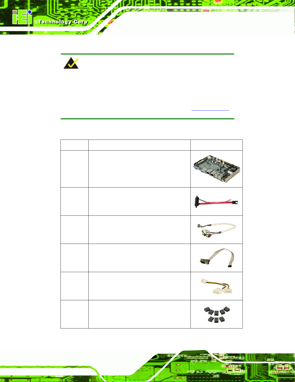
The NANO-CV-D25502/N26002 is shipped with the following components:
Quantity Item and Part Number Image
1 NANO-CV-D25502/N26002 motherboard
NANO-CV-D25502/N26002 EPIC SBC
1 SATA and power cable
(P/N: 32801-000201-100-RS)
1 Audio cable
(P/N: 32000-072100-RS)
1 RS-232 cable
(P/N: 32205-002700-100-RS)
1 Power cable
(P/N: 32100-087100-RS)
1 Mini jumper pack
Page 10
NANO-CV-D25502/N26002 EPIC SBC
Quantity Item and Part Number Image
1 One Key Recovery CD
1 Utility CD
1 Quick Installation Guide
Table 2-1: Packing List
2.4 Optional Items
The following are optional components which may be separately purchased:
Item and Part Number Image
Dual USB cable (wo bracket)
(P/N: 32000-070301-RS)
RS-422/485 cable (200 mm)
(P/N: 32205-003800-100-RS)
PS/2 KB/MS Y-cable
(P/N: 32000-023800-RS)
Table 2-2: Optional Items
Page 11
NANO-CV-D25502/N26002 EPIC SBC
Chapter
3
3 Connectors
Page 12
NANO-CV-D25502/N26002 EPIC SBC
3.1 Peripheral Interface Connectors
This chapter details all the jumpers and connectors.
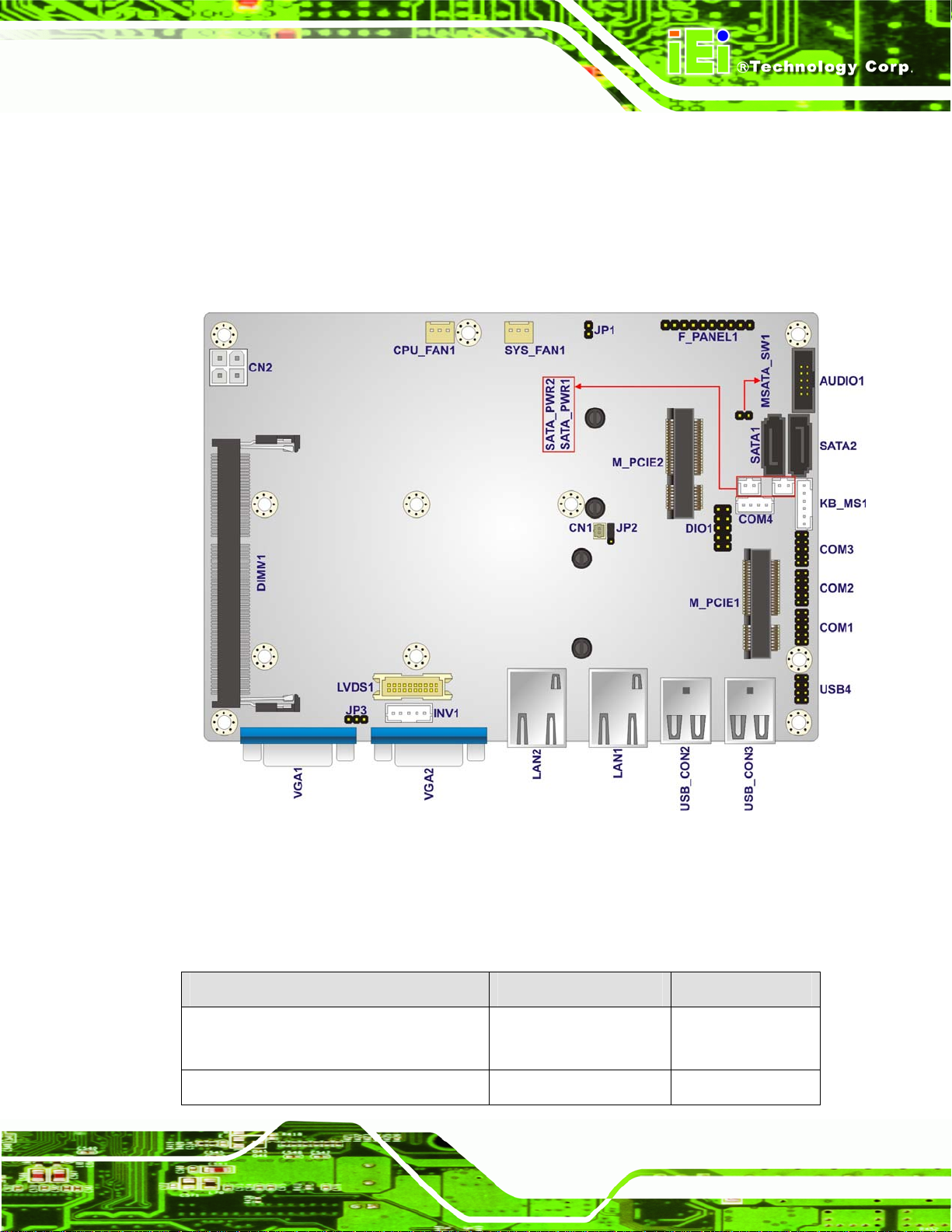
3.1.1 NANO-CV-D25502/N26002 Layout
The figure below shows all the connectors and jumpers.
Figure 3-1: Connectors and Jumpers
3.1.2 Peripheral Interface Connectors
The table below lists all the connectors on the board.
Connector Type Label
5 V SATA power connectors 2-pin wafer SATA_PWR1,
Audio connector 10-pin box header AUDIO1
SATA_PWR2
Page 13
Connector Type Label
Backlight inverter connector 5-pin wafer INV1
Battery connector 2-pin wafer CN1
Digital Input/Output (DIO) connector 10-pin header DIO1
Fan connectors 3-pin wafer CPU_FAN1,
Front panel connector 10-pin header F_PANEL1
Keyboard and mouse connector 6-pin wafer KB_MS1
LVDS connector 20-pin crimp LVDS1
PCIe Mini card slots 52-pin PCIe Mini M_PCIE1,
Power connector (9V~28V) 4-pin connector CN2
NANO-CV-D25502/N26002 EPIC SBC
SYS_FAN2
M_PCIE2
RS-232 serial port connectors 10-pin header COM1, COM2,
COM3
RS-422/485 serial port connector 4-pin wafer COM4
Serial ATA (SATA) drive connectors 7-pin SATA SATA1, SATA2
SO-DIMM connector SO-DIMM connector DIMM1
USB 2.0 connector 8-pin header USB4
Table 3-1: Peripheral Interface Connectors
3.1.3 External Interface Panel Connectors
The table below lists the connectors on the external I/O panel.
Connector Type Label
Ethernet connectors RJ-45 LAN1, LAN2
USB connectors USB 2.0 USB_CON2,
USB_CON3
Page 14
VGA connectors 15-pin female VGA1, VGA2
Table 3-2: Rear Panel Connectors
NANO-CV-D25502/N26002 EPIC SBC
3.2 Internal Peripheral Connectors
The section describes all of the connectors on the NANO-CV-D25502/N26002.
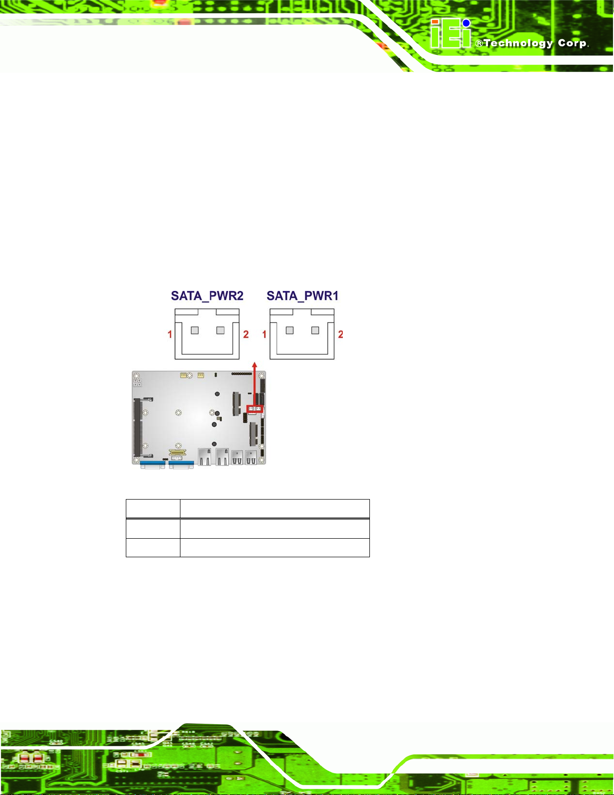
3.2.1 5 V SATA Power Connectors
CN Label: SATA_PWR1, SATA_PWR2
CN Type:
CN Location:
CN Pinouts:
Use the 5 V SATA power connectors to connect to SATA device power connection.
Figure 3-2: 5 V SATA Power Connector Locations
2-pin wafer
See Figure 3-2
See Table 3-3
Pin No. Description
1 +5V
2 Ground
Table 3-3: 5 V SATA Power Connector Pinouts
3.2.2 Audio Connector
CN Label: AUDIO1
CN Type:
CN Location:
CN Pinouts:
10-pin box header
Figure 3-3
See
Table 3-4
See
Page 15
 Loading...