

Page 1
IMBA-C2260-i2 A TX Motherboard
MODEL:
IMBA-C2260-i2
ATX Motherboard Supports LGA1150 Intel® Xeon® E3,
Core™ i3, Pentium® or Celeron® CPU, Intel® C226 Chipset,
DDR3, VGA, iDP, Dual Intel® PCIe GbE, Six SATA 6Gb/s,
Four USB 3.0, HD Audio, iRIS-2400 and RoHS
User Manual
Rev. 1.01 – 18 February, 2014
Page i
Page 2

IMBA-C2260-i2 A TX Motherboard
Revision
Date Version Changes
18 February, 2014
14 January, 2014
1.01 Changed the PCIEX4_1 slot to a PCIe x1 slot
1.00 Initial release
Page ii
Page 3

IMBA-C2260-i2 A TX Motherboard
COPYRIGHT NOTICE
The information in this document is subject to change without prior notice in order to
improve reliability, design and function and does not represent a commitment on the part
of the manufacturer.
In no event will the manufacturer be liable for direct, indirect, special, incidental, or
consequential damages arising out of the use or inability to use the product or
documentation, even if advised of the possibility of such damages.
This document contains proprietary information protected by copyright. All rights are
Copyright
reserved. No part of this manual may be reproduced by any mechanical, electronic, or
other means in any form without prior written permission of the manufacturer.
TRADEMARKS
All registered trademarks and product names mentioned herein are used for identification
purposes only and may be trademarks and/or registered trademarks of their respective
owners.
Page iii
Page 4

IMBA-C2260-i2 A TX Motherboard
Table of Contents
1 INTRODUCTION.......................................................................................................... 1
1.1 INTRODUCTION........................................................................................................... 2
1.2 FEATURES................................................................................................................... 3
1.3 CONNECTORS ............................................................................................................. 4
1.4 DIMENSIONS............................................................................................................... 5
1.5 DATA FLOW................................................................................................................ 6
1.6 TECHNICAL SPECIFICATIONS ...................................................................................... 7
2 PACKING LIST........................................................................................................... 10
2.1 ANTI-STATIC PRECAUTIONS.......................................................................................11
2.2 UNPACKING PRECAUTIONS........................................................................................11
2.3 PACKING LIST........................................................................................................... 12
2.4 OPTIONAL ITEMS...................................................................................................... 13
3 CONNECTORS ........................................................................................................... 15
3.1 PERIPHERAL INTERFACE CONNECTORS..................................................................... 16
3.1.1 IMBA-C2260-i2 Layout ................................................................................... 16
3.1.2 Peripheral Interface Connectors ..................................................................... 17
3.1.3 External Interface Panel Connectors............................................................... 18
3.2 INTERNAL PERIPHERAL CONNECTORS...................................................................... 19
3.2.1 +12V ATX Power Connector ........................................................................... 19
3.2.2 Additional Power Connector ........................................................................... 20
3.2.3 ATX Power Connector ..................................................................................... 20
3.2.4 Battery Connector............................................................................................ 22
3.2.5 Chassis Intrusion Connector............................................................................ 23
3.2.6 DDR3 DIMM Slots........................................................................................... 23
3.2.7 Digital I/O Connector...................................................................................... 24
3.2.8 EC Debug Connector....................................................................................... 25
3.2.9 Fan Connector (CPU)...................................................................................... 26
3.2.10 Fan Connectors (System)............................................................................... 27
3.2.11 Front Panel Audio Connector........................................................................ 27
Page iv
Page 5

IMBA-C2260-i2 A TX Motherboard
3.2.12 Front Panel Connector.................................................................................. 28
3.2.13 I2C Connector................................................................................................ 29
3.2.14 Internal DisplayPort Connector.................................................................... 30
3.2.15 iRIS Module Slot............................................................................................ 31
3.2.16 Keyboard and Mouse Connector................................................................... 32
3.2.17 LAN LED Connectors.................................................................................... 33
3.2.18 mSATA Card Slot............................................................................................ 34
3.2.19 Parallel Port Connector ................................................................................ 36
3.2.20 PCI Slots ........................................................................................................ 37
3.2.21 PCIe x1 Slots.................................................................................................. 38
3.2.22 PCIe x4 Slots.................................................................................................. 38
3.2.23 PCI Express x16 Slot...................................................................................... 39
3.2.24 Power Button ................................................................................................. 40
3.2.25 SATA 6Gb/s Drive Connector ........................................................................ 41
3.2.26 Serial Port Connector, RS-232....................................................................... 42
3.2.27 Serial Port Connector, RS-422/485................................................................ 43
3.2.28 SMBus Connector .......................................................................................... 44
3.2.29 SPI Flash Connector...................................................................................... 45
3.2.30 SPI Flash Connector, EC............................................................................... 46
3.2.31 TPM Connector.............................................................................................. 47
3.2.32 USB 2.0 Connectors....................................................................................... 48
3.3 EXTERNAL PERIPHERAL INTERFACE CONNECTOR PANEL ......................................... 49
3.3.1 Audio Connector .............................................................................................. 49
3.3.2 Ethernet and USB 3.0 Connectors................................................................... 50
3.3.3 Keyboard/Mouse and USB 2.0 Connectors..................................................... 51
3.3.4 Serial Port and VGA Connector...................................................................... 52
3.3.5 USB 2.0 Connectors......................................................................................... 53
4 INSTALLATION ......................................................................................................... 54
4.1 ANTI-STATIC PRECAUTIONS...................................................................................... 55
4.2 INSTALLATION CONSIDERATIONS.............................................................................. 55
4.2.1 Socket LGA1150 CPU Installation .................................................................. 57
4.2.2 Socket LGA1150 Cooling Kit Installation........................................................ 60
4.2.3 DIMM Installation........................................................................................... 62
4.3 IRIS MODULE INSTALLATION................................................................................... 63
Page v
Page 6

IMBA-C2260-i2 A TX Motherboard
4.4 MSATA CARD INSTALLATION................................................................................... 64
4.5 SYSTEM CONFIGURATION......................................................................................... 66
4.5.1 AT/ATX Power Mode Setting........................................................................... 66
4.5.2 Clear CMOS Button......................................................................................... 66
4.5.3 Flash Descriptor Security Override................................................................. 67
4.5.4 mSATA Slot Setup............................................................................................. 68
4.5.5 PCIe x16 Interface Setup................................................................................. 68
4.5.6 USB Power Selection....................................................................................... 69
4.6 INTERNAL PERIPHERAL DEVICE CONNECTIONS........................................................ 70
4.6.1 SATA Drive Connection ................................................................................... 70
4.7 EXTERNAL PERIPHERAL INTERFACE CONNECTION ................................................... 71
4.7.1 Audio Connector .............................................................................................. 71
4.7.2 LAN Connection............................................................................................... 72
4.7.3 PS/2 Keyboard and Mouse Connection........................................................... 73
4.7.4 Serial Device Connection ................................................................................ 74
4.7.5 USB Device Connection................................................................................... 75
4.7.6 VGA Monitor Connection ................................................................................ 76
4.8 INTEL
®
AMT SETUP PROCEDURE............................................................................. 77
4.9 IPMI SETUP PROCEDURE ......................................................................................... 78
4.9.1 Managed System Hardware Setup ................................................................... 78
4.9.2 Using the IEI iMAN Web GUI.......................................................................... 78
5 BIOS.............................................................................................................................. 81
5.1 INTRODUCTION......................................................................................................... 82
5.1.1 Starting Setup................................................................................................... 82
5.1.2 Using Setup...................................................................................................... 82
5.1.3 Getting Help..................................................................................................... 83
5.1.4 Unable to Reboot after Configuration Changes.............................................. 83
5.1.5 BIOS Menu Bar................................................................................................ 83
5.2 MAIN........................................................................................................................ 85
5.3 ADVANCED............................................................................................................... 86
5.3.1 ACPI Settings................................................................................................... 87
5.3.2 RTC Wake Settings........................................................................................... 88
5.3.3 T rusted Computing........................................................................................... 89
5.3.4 CPU Configuration.......................................................................................... 90
Page vi
Page 7

IMBA-C2260-i2 A TX Motherboard
5.3.5 SATA Configuration.......................................................................................... 91
5.3.6 Intel(R) Rapid Start Technology....................................................................... 92
5.3.7 AMT Configuration.......................................................................................... 93
5.3.8 USB Configuration........................................................................................... 94
5.3.9 F81866 Super IO Configuration...................................................................... 95
5.3.9.1 Serial Port n Configuration....................................................................... 96
5.3.9.2 Parallel Port Configuration..................................................................... 101
5.3.10 iWDD H/W Monitor..................................................................................... 102
5.3.10.1 Smart Fan Mode Configuration............................................................ 104
5.3.11 Serial Port Console Redirection................................................................... 105
5.3.12 iEi Feature....................................................................................................110
5.4 CHIPSET ..................................................................................................................111
5.4.1 PCH-IO Configuration ...................................................................................112
5.4.1.1 PCI Express Configuration......................................................................114
5.4.2 System Agent (SA) Configuration ...................................................................116
5.4.2.1 Graphics Configuration............................................................................116
5.4.2.2 NB PCIe Configuration............................................................................119
5.4.2.3 Memory Configuration ........................................................................... 120
5.5 BOOT...................................................................................................................... 121
5.6 SECURITY............................................................................................................... 123
5.7 SAVE & EXIT .......................................................................................................... 123
6 SOFTWARE DRIVERS............................................................................................ 125
6.1 AVAILABLE SOFTWARE DRIVERS ............................................................................ 126
6.2 SOFTWARE INSTALLATION...................................................................................... 126
6.3 CHIPSET DRIVER INSTALLATION............................................................................. 128
6.4 GRAPHICS DRIVER INSTALLATION.......................................................................... 131
6.5 LAN DRIVER INSTALLATION.................................................................................. 134
6.6 USB 3.0 DRIVER INSTALLATION ............................................................................ 138
6.7 AUDIO DRIVER INSTALLATION ............................................................................... 141
6.8 INTEL® AMT DRIVER INSTALLATION .................................................................... 143
A BIOS OPTIONS ........................................................................................................ 147
B ONE KEY RECOVERY........................................................................................... 151
B.1 ONE KEY RECOVERY INTRODUCTION .................................................................... 152
Page vii
Page 8

B.1.1 System Requirement....................................................................................... 153
B.1.2 Supported Operating System......................................................................... 154
B.2 SETUP PROCEDURE FOR WINDOWS........................................................................ 155
B.2.1 Hardware and BIOS Setup ............................................................................ 156
B.2.2 Create Partitions........................................................................................... 156
B.2.3 Install Operating System, Drivers and Applications..................................... 160
B.2.4 Build-up Recovery Partition.......................................................................... 161
B.2.5 Create Factory Default Image....................................................................... 163
B.3 AUTO RECOVERY SETUP PROCEDURE.................................................................... 168
B.4 SETUP PROCEDURE FOR LINUX.............................................................................. 173
B.5 RECOVERY TOOL FUNCTIONS ................................................................................ 176
B.5.1 Factory Restore............................................................................................. 178
B.5.2 Backup System............................................................................................... 179
B.5.3 Restore Your Last Backup.............................................................................. 180
IMBA-C2260-i2 A TX Motherboard
B.5.4 Manual........................................................................................................... 181
B.6 RESTORE SYSTEMS FROM A LINUX SERVER THROUGH LAN.................................. 182
B.6.1 Configure DHCP Server Settings.................................................................. 183
B.6.2 Configure TFTP Settings ............................................................................... 184
B.6.3 Configure One Key Recovery Server Settings............................................... 185
B.6.4 Start the DHCP, TFTP and HTTP................................................................. 186
B.6.5 Create Shared Directory................................................................................ 186
B.6.6 Setup a Client System for Auto Recovery...................................................... 187
B.7 OTHER INFORMATION ............................................................................................ 190
B.7.1 Using AHCI Mode or ALi M5283 / VIA VT6421A Controller....................... 190
B.7.2 System Memory Requirement ........................................................................ 192
C TERMINOLOGY ..................................................................................................... 193
D DIGITAL I/O INTERFACE..................................................................................... 197
D.1 INTRODUCTION...................................................................................................... 198
D.2 DIO CONNECTOR PINOUTS ................................................................................... 198
D.3 ASSEMBLY LANGUAGE SAMPLES........................................................................... 198
D.3.1 Enable the DIO Input Function .................................................................... 198
D.3.2 Enable the DIO Output Function.................................................................. 199
E WA TCHDOG TIMER............................................................................................... 200
Page viii
Page 9

IMBA-C2260-i2 A TX Motherboard
F INTEL® MATRIX STORAGE MANAGER.......................................................... 203
F.1 INTRODUCTION....................................................................................................... 204
F.1.1 Precautions .................................................................................................... 204
F.2 FEATURES AND BENEFITS ....................................................................................... 205
F.3 ACCESSING THE INTEL® MATRIX STORAGE MANAGER.......................................... 205
F.4 INSTALLING THE OPERATING SYSTEM TO THE RAID ARRAY .................................. 206
G HAZARDOUS MATERIALS DISCLOSURE....................................................... 207
G.1 HAZARDOUS MATERIALS DISCLOSURE TABLE FOR IPB PRODUCTS CERTIFIED AS
ROHS COMPLIANT UNDER 2002/95/EC WITHOUT MERCURY..................................... 208
Page ix
Page 10

IMBA-C2260-i2 A TX Motherboard
List of Figures
Figure 1-1: IMBA-C2260-i2.............................................................................................................2
Figure 1-2: Connectors ..................................................................................................................4
Figure 1-3: IMBA-C2260-i2 Dimensions (mm)..............................................................................5
Figure 1-4: Data Flow Diagram......................................................................................................6
Figure 3-1: Peripheral Interface Connectors .............................................................................16
Figure 3-2: +12V ATX Power Connector Pinout Location ........................................................19
Figure 3-3: Additional Power Connector Location....................................................................20
Figure 3-4: ATX Power Connector Location..............................................................................21
Figure 3-5: Battery Connector Location.....................................................................................22
Figure 3-6: Chassis Intrusion Connector Location...................................................................23
Figure 3-7: DDR3 DIMM Slot Locations......................................................................................24
Figure 3-8: Digital I/O Connector Location ................................................................................24
Figure 3-9: EC Debug Connector Location................................................................................25
Figure 3-10: CPU Fan Connector Location................................................................................26
Figure 3-11: System Fan Connector Locations.........................................................................27
Figure 3-12: Front Panel Audio Connector Location................................................................28
Figure 3-13: Front Panel Connector Location ...........................................................................29
Figure 3-14: I2C Connector Location ..........................................................................................30
Figure 3-15: Internal DisplayPort Connector Location.............................................................31
Figure 3-16: iRIS Module Slot Location......................................................................................32
Figure 3-17: Keyboard and Mouse Connector Location...........................................................33
Figure 3-18: LAN LED Connector Locations .............................................................................34
Figure 3-19: mSATA Card Slot Location....................................................................................35
Figure 3-20: Parallel Port Connector Location..........................................................................36
Figure 3-21: PCI Slot Locations ..................................................................................................37
Figure 3-22: PCIe x1 Slot Locations ...........................................................................................38
Figure 3-23: PCIe x4 Slot Locations ...........................................................................................39
Figure 3-24: PCIe x16 Slot Location ...........................................................................................40
Figure 3-25: Power Button Location...........................................................................................40
Figure 3-26: SATA 6Gb/s Drive Connector Location................................................................41
Page x
Page 11

IMBA-C2260-i2 A TX Motherboard
Figure 3-27: RS-232 Serial Port Connector Location................................................................42
Figure 3-28: RS-422/485 Connector Location............................................................................44
Figure 3-29: SMBus Connector Location...................................................................................45
Figure 3-30: SPI Flash Connector Location...............................................................................45
Figure 3-31: SPI EC Flash Connector Location.........................................................................46
Figure 3-32: TPM Connector Location........................................................................................47
Figure 3-33: USB 2.0 Connector Pinout Locations...................................................................48
Figure 3-34: External Peripheral Interface Connector..............................................................49
Figure 3-35: Audio Connector.....................................................................................................50
Figure 3-36: Serial Port Connector Pinouts...............................................................................52
Figure 3-37: VGA Connector .......................................................................................................53
Figure 4-1: Disengage the CPU Socket Load Lever..................................................................57
Figure 4-2: Remove Protective Cover.........................................................................................58
Figure 4-3: Insert the Socket LGA1150 CPU..............................................................................59
Figure 4-4: Close the Socket LGA1150 ......................................................................................59
Figure 4-5: Cooling Kit Support Bracket....................................................................................61
Figure 4-6: DIMM Installation.......................................................................................................62
Figure 4-7: iRIS Module Installation............................................................................................63
Figure 4-8: Remove the Retention Screws for the mSATA Card.............................................64
Figure 4-9: Insert the mSATA Card into the Socket at an Angle.............................................65
Figure 4-10: Secure the mSATA Card.........................................................................................65
Figure 4-11: AT/ATX Power Mode Switch Location..................................................................66
Figure 4-12: Clear CMOS Button Location.................................................................................67
Figure 4-13: Flash Descriptor Security Override Jumper Location ........................................67
Figure 4-14: mSATA Slot Setup Jumper Location....................................................................68
Figure 4-15: SATA Drive Cable Connection...............................................................................70
Figure 4-16: SATA Power Drive Connection..............................................................................71
Figure 4-17: Audio Connector.....................................................................................................72
Figure 4-18: LAN Connection......................................................................................................73
Figure 4-19: PS/2 Keyboard/Mouse Connector.........................................................................74
Figure 4-20: Serial Device Connector.........................................................................................75
Figure 4-21: USB Device Connection.........................................................................................76
Figure 4-22: VGA Connector .......................................................................................................77
Figure 4-23: IEI iMAN Web Address............................................................................................79
Figure 4-24: IEI iMAN Web GUI....................................................................................................80
Page xi
Page 12

Figure 6-1: Introduction Screen............................................................................................... 127
Figure 6-2: Available Drivers.................................................................................................... 127
Figure 6-3: Chipset Driver Welcome Screen........................................................................... 128
Figure 6-4: Chipset Driver License Agreement...................................................................... 129
Figure 6-5: Chipset Driver Read Me File ................................................................................. 129
Figure 6-6: Chipset Driver Setup Operations ......................................................................... 130
Figure 6-7: Chipset Driver Installation Finish Screen............................................................ 130
Figure 6-8: Graphics Driver Welcome Screen........................................................................ 131
Figure 6-9: Graphics Driver License Agreement.................................................................... 132
Figure 6-10: Graphics Driver Read Me File............................................................................. 132
Figure 6-11: Graphics Driver Setup Operations..................................................................... 133
Figure 6-12: Graphics Driver Installation Finish Screen ....................................................... 133
Figure 6-13: Intel® Network Connection Menu....................................................................... 134
Figure 6-14: LAN Driver Welcome Screen .............................................................................. 135
IMBA-C2260-i2 A TX Motherboard
Figure 6-15: LAN Driver License Agreement.......................................................................... 135
Figure 6-16: LAN Driver Setup Options................................................................................... 136
Figure 6-17: LAN Driver Installation ........................................................................................ 137
Figure 6-18: LAN Driver Installation Complete....................................................................... 137
Figure 6-19: USB 3.0 Driver Welcome Screen........................................................................ 138
Figure 6-20: USB 3.0 Driver License Agreement.................................................................... 139
Figure 6-21: USB 3.0 Driver Read Me File............................................................................... 139
Figure 6-22: USB 3.0 Driver Setup Operations....................................................................... 140
Figure 6-23: USB 3.0 Driver Installation Finish Screen ......................................................... 141
Figure 6-24: InstallShield Wizard Welcome Screen............................................................... 142
Figure 6-25: Audio Driver Software Configuration................................................................. 142
Figure 6-26: Restart the Computer .......................................................................................... 143
Figure 6-27: Intel® ME Driver Welcome Screen ..................................................................... 144
Figure 6-28: Intel® ME Driver License Agreement................................................................. 145
Figure 6-29: Intel® ME Driver Setup Operations.................................................................... 145
Figure 6-30: Intel® ME Driver Installation Finish Screen ...................................................... 146
Figure B-1: IEI One Key Recovery Tool Menu........................................................................ 152
Figure B-2: Launching the Recovery Tool.............................................................................. 157
Figure B-3: Recovery Tool Setup Menu .................................................................................. 157
Figure B-4: Command Mode..................................................................................................... 158
Figure B-5: Partition Creation Commands.............................................................................. 159
Page xii
Page 13

IMBA-C2260-i2 A TX Motherboard
Figure B-6: Launching the Recovery Tool.............................................................................. 161
Figure B-7: Manual Recovery Environment for Windows..................................................... 161
Figure B-8: Building the Recovery Partition........................................................................... 162
Figure B-9: Press Any Key to Continue.................................................................................. 162
Figure B-10: Press F3 to Boot into Recovery Mode............................................................... 163
Figure B-11: Recovery Tool Menu ........................................................................................... 163
Figure B-12: About Symantec Ghost Window........................................................................ 164
Figure B-13: Symantec Ghost Path ......................................................................................... 164
Figure B-14: Select a Local Source Drive ............................................................................... 165
Figure B-15: Select a Source Partition from Basic Drive ...................................................... 165
Figure B-16: File Name to Copy Image to ............................................................................... 166
Figure B-17: Compress Image.................................................................................................. 166
Figure B-18: Image Creation Confirmation............................................................................. 167
Figure B-19: Image Creation Complete................................................................................... 167
Figure B-20: Image Creation Complete................................................................................... 167
Figure B-21: Press Any Key to Continue................................................................................ 168
Figure B-22: Auto Recovery Utility.......................................................................................... 169
Figure B-23: Disable Automatically Restart............................................................................ 169
Figure B-24: Launching the Recovery Tool............................................................................ 170
Figure B-25: Auto Recovery Environment for Windows ....................................................... 170
Figure B-26: Building the Auto Recovery Partition................................................................ 171
Figure B-27: Factory Default Image Confirmation ................................................................. 171
Figure B-28: Image Creation Complete................................................................................... 172
Figure B-29: Press any key to continue.................................................................................. 172
Figure B-30: Partitions for Linux.............................................................................................. 174
Figure B-31: System Configuration for Linux......................................................................... 175
Figure B-32: Access menu.lst in Linux (Text Mode).............................................................. 175
Figure B-33: Recovery Tool Menu ........................................................................................... 176
Figure B-34: Recovery Tool Main Menu.................................................................................. 177
Figure B-35: Restore Factory Default...................................................................................... 178
Figure B-36: Recovery Complete Window.............................................................................. 178
Figure B-37: Backup System.................................................................................................... 179
Figure B-38: System Backup Complete Window ................................................................... 179
Figure B-39: Restore Backup................................................................................................... 180
Figure B-40: Restore System Backup Complete Window..................................................... 180
Page xiii
Page 14

Figure B-41: Symantec Ghost Window ................................................................................... 181
Figure B-42: Disable Automatically Restart............................................................................ 188
IMBA-C2260-i2 A TX Motherboard
Page xiv
Page 15

IMBA-C2260-i2 A TX Motherboard
List of Tables
Table 1-1: IMBA-C2260-i2 Specifications.....................................................................................9
Table 2-1: Packing List.................................................................................................................12
Table 2-2: Optional Items.............................................................................................................14
Table 3-1: Peripheral Interface Connectors...............................................................................18
Table 3-2: Rear Panel Connectors..............................................................................................19
Table 3-3: +12V ATX Power Connector Pinouts........................................................................19
Table 3-4: Additional Power Connector Pinouts.......................................................................20
Table 3-5: ATX Power Connector Pinouts .................................................................................21
Table 3-6: Chassis Intrusion Connector Pinouts......................................................................23
Table 3-7: Digital I/O Connector Pinouts....................................................................................25
Table 3-8: EC Debug Connector Pinouts ...................................................................................26
Table 3-9: CPU Fan Connector Pinouts......................................................................................26
Table 3-10: System Fan Connector Pinouts..............................................................................27
Table 3-11: Front Panel Audio Connector Pinouts ...................................................................28
Table 3-12: Front Panel Connector Pinouts...............................................................................29
Table 3-13: I2C Connector Pinouts..............................................................................................30
Table 3-14: Internal DisplayPort Connector Pinouts ................................................................31
Table 3-15: Keyboard and Mouse Connector Pinouts..............................................................33
Table 3-16: LAN1 LED Connector (LED_LAN1) Pinouts...........................................................34
Table 3-17: LAN2 LED Connector (LED_LAN2) Pinouts...........................................................34
Table 3-18: mSATA Card Slot Pinouts........................................................................................36
Table 3-19: Parallel Port Connector Pinouts .............................................................................37
Table 3-20: SATA 6Gb/s Drive Connector Pinouts....................................................................41
Table 3-21: RS-232 Serial Port Connector Pinouts...................................................................43
Table 3-22: RS-422/485 Connector Pinouts...............................................................................44
Table 3-23: DB-9 RS-422/485 Pinouts.........................................................................................44
Table 3-24: SMBus Connector Pinouts ......................................................................................45
Table 3-25: SPI Flash Connector Pinouts ..................................................................................46
Table 3-26: SPI EC Flash Connector Pinouts ............................................................................46
Table 3-27: TPM Connector Pinouts...........................................................................................47
Page xv
Page 16

Table 3-28: USB 2.0 Connector Pinouts.....................................................................................48
Table 3-29: USB 3.0 Port Pinouts................................................................................................50
Table 3-30: LAN Pinouts ..............................................................................................................51
Table 3-31: USB 2.0 Port Pinouts................................................................................................51
Table 3-32: PS/2 Connector Pinouts...........................................................................................51
Table 3-33: Serial Port Connector Pinouts ................................................................................52
Table 3-34: VGA Connector Pinouts...........................................................................................53
Table 3-35: USB 2.0 Port Pinouts................................................................................................53
Table 4-1: AT/ATX Power Mode Switch Settings.......................................................................66
Table 4-2: Flash Descriptor Security Override Jumper Settings.............................................67
Table 4-3: mSATA Slot Setup Jumper Settings.........................................................................68
Table 4-4: PCIe x16 Interface Setup............................................................................................69
Table 4-5: BIOS Options and Configured USB Ports................................................................69
Table 4-6: USB Power Source Setup..........................................................................................69
IMBA-C2260-i2 A TX Motherboard
Table 5-1: BIOS Navigation Keys................................................................................................83
Table 5-2: BIOS Options and Configured USB Ports............................................................. 114
Table 6-1: Digital I/O Connector Pinouts................................................................................. 198
Page xvi
Page 17

IMBA-C2260-i2 A TX Motherboard
BIOS Menus
BIOS Menu 1: Main.......................................................................................................................85
BIOS Menu 2: Advanced..............................................................................................................86
BIOS Menu 3: ACPI Configuration..............................................................................................87
BIOS Menu 4: RTC Wake Settings..............................................................................................88
BIOS Menu 5: Trusted Computing..............................................................................................89
BIOS Menu 6: CPU Configuration...............................................................................................90
BIOS Menu 7: SATA Configuration.............................................................................................91
BIOS Menu 8: Intel(R) Rapid Start Technology .........................................................................92
BIOS Menu 9: AMT Configuration...............................................................................................93
BIOS Menu 10: USB Configuration.............................................................................................94
BIOS Menu 11: F81866 Super IO Configuration........................................................................95
BIOS Menu 12: Serial Port n Configuration Menu.....................................................................96
BIOS Menu 13: Parallel Port Configuration Menu.................................................................. 101
BIOS Menu 14: iWDD H/W Monitor .......................................................................................... 103
BIOS Menu 15: Smart Fan Mode Configuration ..................................................................... 104
BIOS Menu 16: Serial Port Console Redirection.................................................................... 106
BIOS Menu 17: iEi Feature........................................................................................................ 110
BIOS Menu 18: Chipset............................................................................................................. 111
BIOS Menu 19: PCH-IO Configuration..................................................................................... 112
BIOS Menu 20: PCI Express Configuration ............................................................................ 114
BIOS Menu 21: PCIEX1_1 and PCIEX4_1 Configuration Menu............................................. 115
BIOS Menu 22: System Agent (SA) Configuration................................................................. 116
BIOS Menu 23: Graphics Configuration.................................................................................. 117
BIOS Menu 24: LCD Control..................................................................................................... 118
BIOS Menu 25: NB PCIe Configuration ................................................................................... 119
BIOS Menu 26: Memory Configuration.................................................................................... 120
BIOS Menu 27: Boot.................................................................................................................. 121
BIOS Menu 28: Security............................................................................................................ 123
BIOS Menu 29: Save & Exit....................................................................................................... 124
BIOS Menu 30: IEI Feature........................................................................................................ 173
Page xvii
Page 18
IMBA-C2260-i2 A TX Motherboard
Chapter
1
1 Introduction
Page 1
Page 19
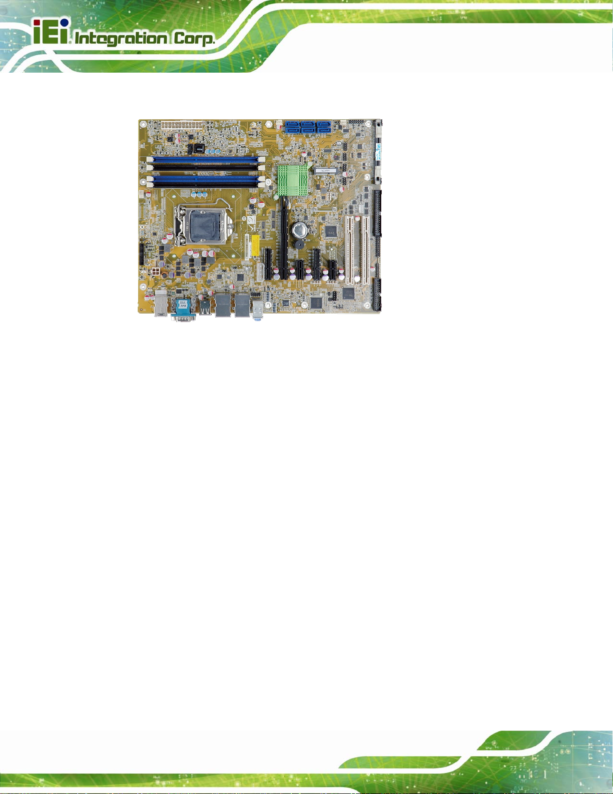
1.1 Introduction
Figure 1-1: IMBA-C2260-i2
IMBA-C2260-i2 A TX Motherboard
The IMBA-C2260-i2 is an ATX motherboard. It accepts a Socket LGA1150 Intel® Xeon®
E3, Core™ i3, Pentium® or Celeron® processor and supports four 240-pin
1600/1333 MHz dual-channel DDR3 DIMM modules up to 32 GB.
The IMBA-C2260-i2 provides two GbE interfaces through the Intel® I217 (with Intel® AMT
9.0 support) and the Intel® I210 PCIe controllers. The integrated Intel® C226 chipset
supports six SATA 6Gb/s drives. In addition, the IMBA-C2260-i2 includes VGA and iDP
interfaces for dual independent display.
Expansion and I/O include two PCI slots, one PCIe x16 slot with x8 signal, two PCIe x4
slots, two PCIe x1 slots, four USB 3.0 and four USB 2.0 on the rear panel, fou r USB 2.0 by
pin headers, six COM ports and one mSATA card slot. High Definition Audio (HDA)
support ensures HDA devices can be easily implemented on the IMBA-C2260-i2.
Page 2
Page 20

IMBA-C2260-i2 A TX Motherboard
1.2 Features
Some of the IMBA-C2260-i2 motherboard features are listed below:
ATX form factor
LGA1150 Intel® Xeon® E3, Core™ i3, Pentium® or Celeron® processor
supported
Intel® C226 chipset
Four 240-pin 1600/1333 MHz dual-channel DDR3 DIMMs support up to 32 GB
Two Intel® PCIe GbE connectors (LAN1 with Intel® AMT 9.0 support)
Supports PCI Express Generation 3.0 at 8 GT/s I/O bandwidth
Dual independent display by VGA and iDP interfaces
Supports IPMI 2.0 via iRIS-2400 module
Six SATA 6Gb/s connectors support RAID 0, 1, 5, 10
Four USB 3.0 ports on the rear panel
One mSATA card slot
One PCIe x16 slot with x8 signal
Two PCIe x4 slots
Two PCIe x1 slots
Two PCI slots
Six COM ports
TPM V1.2 hardware security function supported by TPM module
High Definition Audio
RoHS compliant
Page 3
Page 21
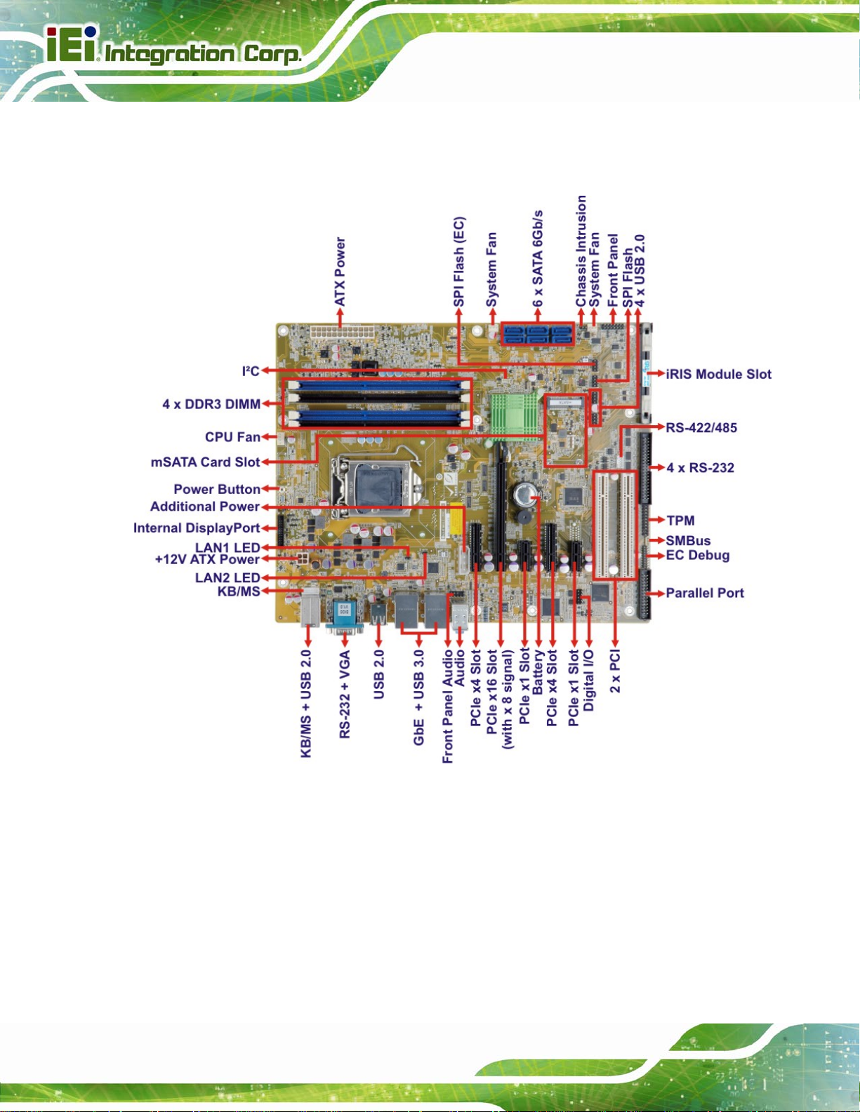
1.3 Connectors
The connectors on the IMBA-C2260-i2 are shown in the figure below.
IMBA-C2260-i2 A TX Motherboard
Figure 1-2: Connectors
Page 4
Page 22
IMBA-C2260-i2 A TX Motherboard
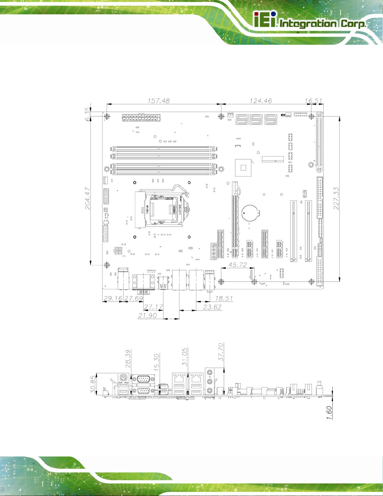
1.4 Dimensions
The main dimensions of the IMBA-C2260-i2 are shown in the diagram below.
Figure 1-3: IMBA-C2260-i2 Dimensions (mm)
Page 5
Page 23
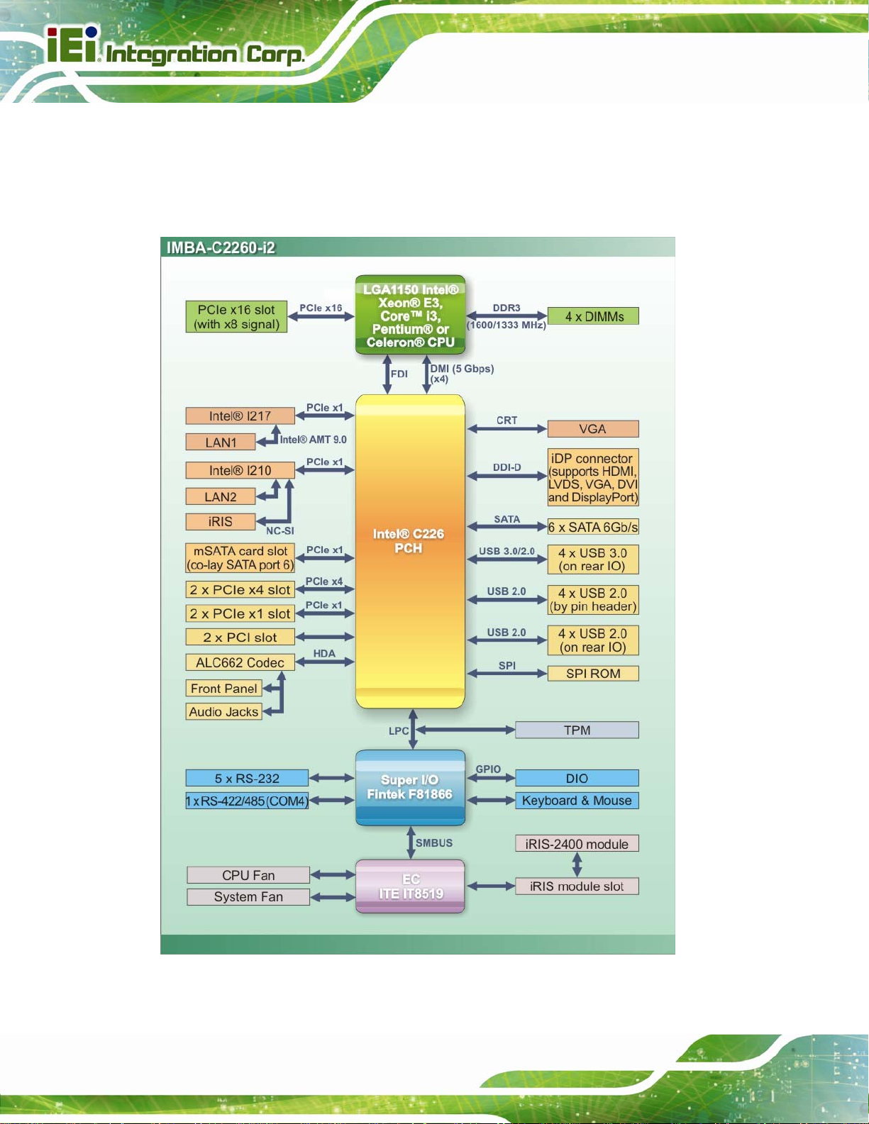
1.5 Data Flow
8Figure 1-4 shows the data flow between the system chipset, the CPU and other
components installed on the motherboard.
IMBA-C2260-i2 A TX Motherboard
Figure 1-4: Data Flow Diagram
Page 6
Page 24
IMBA-C2260-i2 A TX Motherboard
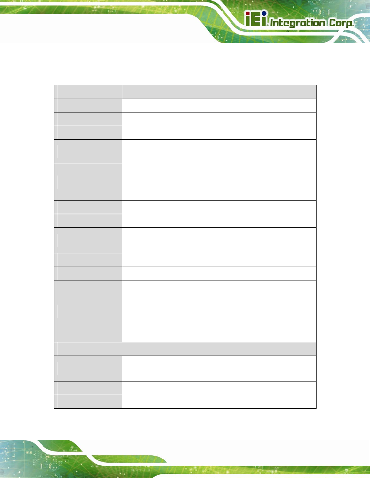
1.6 Technical Specifications
The IMBA-C2260-i2 technical specifications are listed below.
Specification/Model IMBA-C2260-i2
Form Factor
CPU Supported
Chipset
Memory
Graphics Engine
Audio
BIOS
Ethernet Controllers
Super I/O Controller
Watchdog Timer
ATX
LGA1150 Intel® Xeon® E3, Core™ i3, Pentium® or Celeron® CPU
Intel® C226
Four 240-pin 1600/1333 MHz dual-channel ECC/non-ECC unbuffered
DDR3 SDRAM DIMMs support (system max. 32 GB)
Intel® HD Graphics Gen 7.5 supports DirectX 11.1, OpenCL 1.2 and
OpenGL 3.2
Full MPEG2, VC1, AVC Decode
Realtek ALC662 HD Audio codec (line-in, line-out, mic-in)
UEFI BIOS
LAN1: Intel® I217 PHY with Intel® AMT 9.0 support (LAN1_USB1)
LAN2: Intel® I210 PCIe Ethernet controller (LAN1_USB2)
Fintek F81866
Software programmable supports 1~2 55 sec. system reset
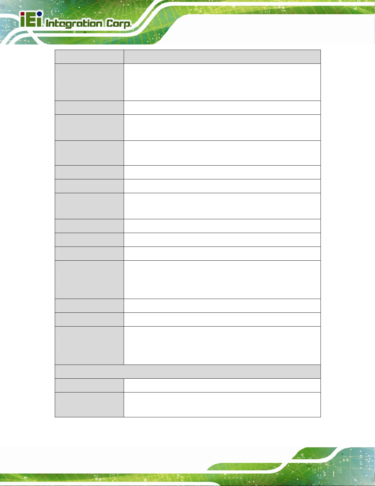
Expansions
I/O Interface Connectors
Audio Connectors
Chassis Intrusion
Digital I/O
Two PCI slots
One PCIe x16 slot (with x8 signal)
Two PCIe x4 slots (support PCIe x1)
Two PCIe x1 slots
One mSATA card slot (co-l ay SATA port 6)
Line-in, line-out and mic-in audio jacks on rear panel
One internal front panel audio connector (10-pin header)
One 2-pin header
8-bit, 4-bit input/4-bit output
Page 7
Page 25
Specification/Model IMBA-C2260-i2
One VGA (up to 1920 x 1200, 60 Hz)
IMBA-C2260-i2 A TX Motherboard
Display Output
Ethernet
Fan
Front Panel
I2C
IPMI 2.0
Keyboard and Mouse
LAN LED
Parallel Port
Serial ATA
One iDP interface for HDMI, LVDS, VGA, DVI and DisplayPort (up to
3840 x 2160, 60 Hz)
Two RJ-45 GbE port s
One 4-pin CPU fan connector
One 3-pin system fan connector
One 14-pin header (power LED, HDD LED, IPMI LED, speaker, power
button, reset button)
One 4-pin wafer connector
One iRIS module slot
One PS/2 keyboard/mouse connector
One internal keyboard and mouse connector (6-pin wafer)
Two 2-pin headers for LAN1 LED and LAN2 LED
One parallel port via internal 26-pin box header
Six SATA 6Gb/s connectors (support RAID 0, 1, 5, 10)
One external RS-232 serial port
Serial Ports
SMBus
TPM
USB Ports
Environmental and Power Specifications
Power Supply
Power Consumption
Four RS-232 via internal box header
One RS-422/485 via internal 4-pin wafer connector
One 4-pin wafer connector
One via 20-pin header
Four USB 3.0 ports on rear panel
Four USB 2.0 ports on rear panel
Four internal USB 2.0 ports by pin headers
ATX power supply
3.3V@0.57A, 5V@4.50A, 12V@0.14A, Vcore@5.20A, 5VSB@0.19A
(3.1 GHz Intel® CPU with four 2 GB 1333 MHz DDR3 memory)
Page 8
Page 26
IMBA-C2260-i2 A TX Motherboard
Specification/Model IMBA-C2260-i2
Operating
Temperature
Storage Temperature
Humidity
Physical Specifications
Dimensions
Weight (GW/NW)
Table 1-1: IMBA-C2260-i2 Specifications
-20ºC ~ 60ºC
-30ºC ~ 70ºC
5% ~ 95% (non-condensing)
244 mm x 305 mm
1200 g/700 g
Page 9
Page 27
IMBA-C2260-i2 A TX Motherboard
Chapter
2
2 Packing List
Page 10
Page 28
IMBA-C2260-i2 A TX Motherboard
2.1 Anti-static Precautions
WARNING!
Static electricity can destroy certain electronics. Make sure to follow the
ESD precautions to prevent damage to the product, and injury to the
user.
Make sure to adhere to the following guidelines:
Wear an anti-static wristband: Wearing an anti-static wristband can prevent
electrostatic discharge.
Self-grounding: Touch a grounded conductor every few minutes to discharge
any excess static buildup.
Use an anti-static pad: When configuring any circuit board, place it on an
anti-static mat.
Only handle the edges of the PCB: Don't touch the surface of the
motherboard. Hold the motherboard by the edges when handling.
2.2 Unpacking Precautions
When the IMBA-C2260-i2 is unpacked, please do the following:
Follow the antistatic guidelines above.
Make sure the packing box is facing upwards whe n opening.
Make sure all the packing list items are present.
Page 11
Page 29
2.3 Packing List
NOTE:
If any of the components listed in the checklist below are missing, do
not proceed with the installation. Contact the IEI reseller or vendor the
IMBA-C2260-i2 was purchased from or contact an IEI sales
representative directly by sending an email to 33sales@iei.com.tw.
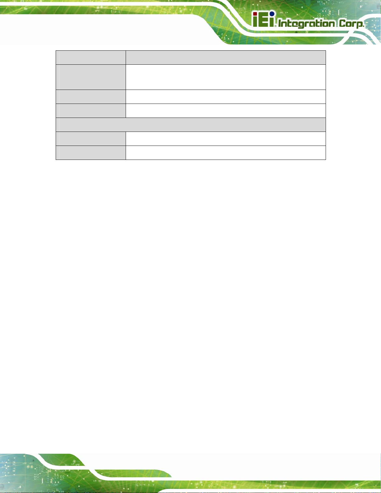
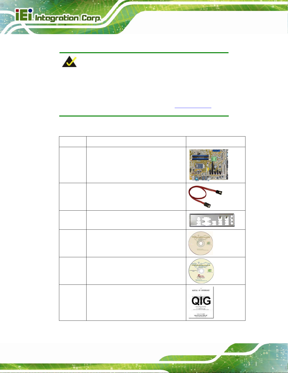
The IMBA-C2260-i2 is shipped with the following components:
Quantity Item and Part Number Image
1 IMBA-C2260-i2 single board computer
IMBA-C2260-i2 A TX Motherboard
2 SATA cable
(P/N: 32000-062800-RS)
1 I/O shielding
(P/N: 45014-0034C0-00-RS)
1 Utility CD
1 One Key Recovery CD
1 Quick Installation Guide
Page 12
Table 2-1: Packing List
Page 30
IMBA-C2260-i2 A TX Motherboard
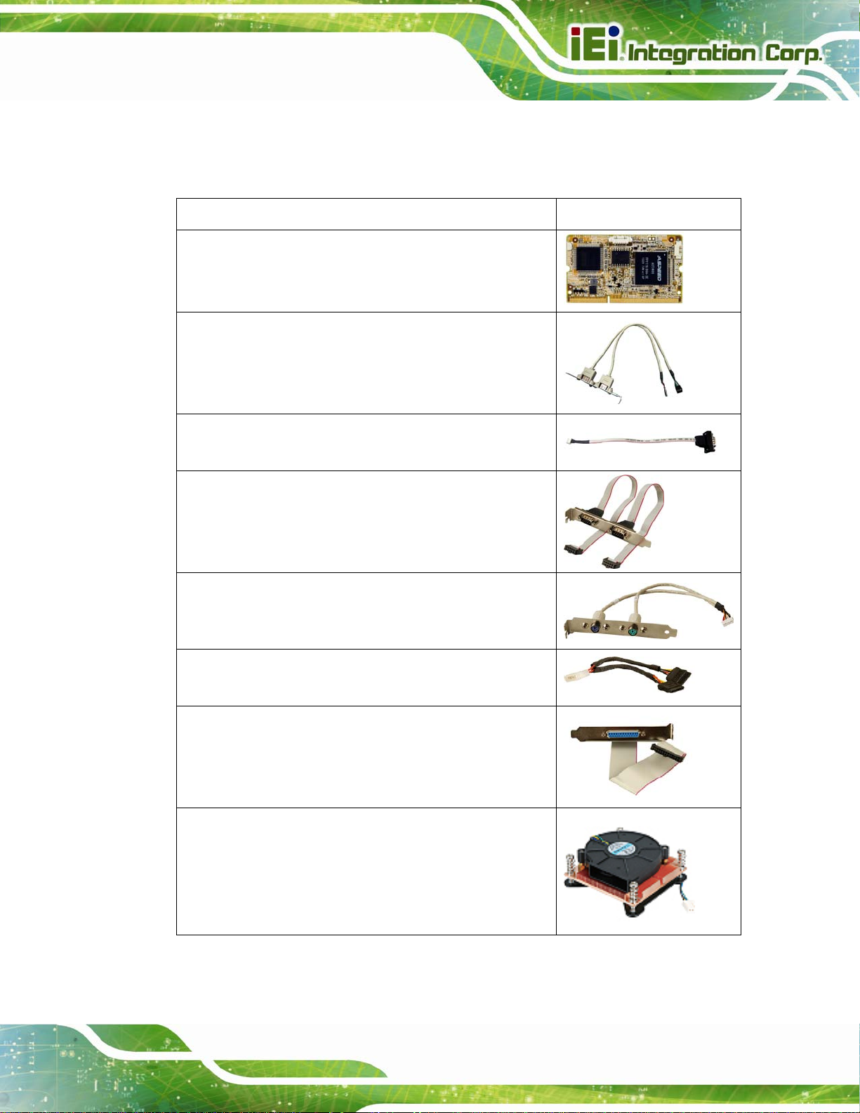
2.4 Optional Items
The following are optional components which may be separately purchased:
Item and Part Number Image
iRIS-2400 module, IPMI 2.0 adapter card with AST2400
BMC chip for DDR3 SO-DIMM socket interface
(P/N: iRIS-2400-R10)
Dual-port USB cable with bracket
(P/N: 19800-003100-200-RS)
RS-422/485 cable, 200 mm
(P/N: 32205-003800-100-RS)
RS-232 cable, 230 mm
(P/N: 19800-000051-RS)
PS/2 KB/MS Y-cable with bracket
(P/N: 19800-000075-RS)
SATA power cable
(P/N: 32102-000100-200-RS)
LPT cable
(P/N: 19800-000049-RS)
LGA1155/LGA1156 cooler kit (1U chassis compatible,
73W)
(P/N: CF-1 156A-RS-R11)
Page 13
Page 31

Item and Part Number Image
LGA1155/LGA1156 cooler kit (95W)
(P/N: CF-1156E-R11)
DisplayPort to HDMI converter board for IEI IDP connector
(P/N: DP-HDMI-R10)
DisplayPort to LVDS converter board for IEI IDP connector
(P/N: DP-LVDS-R10)
DisplayPort to VGA converter board for IEI IDP connector
IMBA-C2260-i2 A TX Motherboard
(P/N: DP-VGA-R10)
DisplayPort to DVI-D converter board for IEI IDP connector
(P/N: DP-DVI-R10)
DisplayPort to DisplayPort converter board for IEI iDP
connector
(P/N: DP-DP-R10)
20-pin Infineon TPM module, software management tool,
firmware v3.17
(P/N: TPM-IN01-R1 1)
Table 2-2: Optional Items
Page 14
Page 32
IMBA-C2260-i2 A TX Motherboard
Chapter
3
3 Connectors
Page 15
Page 33

3.1 Peripheral Interface Connectors
This chapter details all the peripheral interface connectors.
3.1.1 IMBA-C2260-i2 Layout
The figures below show all the peripheral interface connectors.
IMBA-C2260-i2 A TX Motherboard
Page 16
Figure 3-1: Peripheral Interface Connectors
Page 34

IMBA-C2260-i2 A TX Motherboard
3.1.2 Peripheral Interface Connectors
The table below lists all the connectors on the board.
Connector Type Label
+12V ATX power connector
Additional power connector 4-pin connector ATXPWR1
ATX power connector 24-pin connector ATX1
Battery connector Battery holder BAT1
Chassis intrusion connector 2-pin header CHASSIS1
DDR3 DIMM sockets 240-pin socket
Digital I/O connector 10-pin header DIO1
EC debug connector 18-pin header CN3
Fan connector (CPU) 4-pin wafer CPU_FAN1
Fan connectors (system) 3-pin wafer
4-pin Molex power
CPU12V1
connector
CHA_DIMM1,
CHA_DIMM2,
CHB_DIMM1,
CHB_DIMM2
SYS_FAN1,
SYS_FAN2
Front panel audio connector 10-pin header FRONT-PANEL1
Front panel connector 14-pin header F_PANEL1
I2C connector 4-pin wafer CN5
Internal DisplayPort connector 19-pin box header DP1
iRIS module slot iRIS module slot IPMI1
Keyboard and mouse connector 6-pin wafer KB_MS1
LAN1 LED connector 2-pin header LED_LAN1
LAN2 LED connector 2-pin header LED_LAN2
mSATA card slot PCIe Mini slot CN2
Parallel port connector 26-pin box header LPT1
Page 17
Page 35

Connector Type Label
PCI slots PCI slot PCI1, PCI2
IMBA-C2260-i2 A TX Motherboard
PCIe x1 slots PCIe x1 slot
PCIe x4 slots PCIe x4 slot
PCIe x16 slot (with x8 signal) PCIe x16 slot PCIEX16_1
Power button Push button PWR_SW1
SATA 6Gb/s drive connector 7-pin SATA connector
Serial port, RS-232 40-pin box header COM2-6
Serial port, RS-422/485 4-pin wafer COM4
SMBus connector 4-pin wafer CN1
SPI flash connector 8-pin header JSPI1
SPI flash connector, EC 8-pin header JSPI2
PCIEX1_1,
PCIEX4_1
PCIEX4_2,
PCIEX4_3
S_ATA1, S_ATA2,
S_ATA3, S_ATA4,
S_ATA5, S_ATA6
TPM connector 20-pin header TPM1
USB 2.0 connectors 8-pin header USB1, USB2
Table 3-1: Peripheral Interface Connectors
3.1.3 External Interface Panel Connectors
The table below lists the connectors on the external I/O panel.
Connector Type Label
Audio connector Audio jacks AUDIO_CV1
Ethernet and USB 3.0 ports RJ-45, USB 3.0
Keyboard/mouse and USB 2.0 ports PS/2, USB 2.0 K/M_USB1
LAN1_USB1,
LAN1_USB2
Page 18
Page 36

IMBA-C2260-i2 A TX Motherboard
Connector Type Label
Serial port and VGA connector
USB 2.0 ports USB 2.0 CNUSB1
Table 3-2: Rear Panel Connectors
3.2 Internal Peripheral Connectors
The section describes all of the connectors on the IMBA-C2260-i2.
3.2.1 +12V ATX Power Connector
CN Label: CPU12V1
CN Type:
CN Location:
CN Pinouts:
This connector provides power to the CPU.
4-pin Molex power connector
Figure 3-2
See
Table 3-3
See
9-pin male DB-9,
VGACOM1
15-pin female
Figure 3-2: +12V ATX Power Connector Pinout Location
Pin Description Pin Description
1 GND 2 GND
3 +12V 4 +12V
Table 3-3: +12V ATX Power Connector Pinouts
Page 19
Page 37

3.2.2 Additional Power Connector
CN Label: ATXPWR1
IMBA-C2260-i2 A TX Motherboard
CN Type:
CN Location:
CN Pinouts:
The additional power connector provides extra +12V and +5V power to the system.
Figure 3-3: Additional Power Connector Location
4-pin connector
Figure 3-3
See
Table 3-4
See
Pin Description
1 +12V
2 GND
3 GND
4 VCC
Table 3-4: Additional Power Connector Pinouts
3.2.3 ATX Power Connector
CN Label: ATX1
CN Type:
CN Location:
CN Pinouts:
The ATX power connector connects to an ATX power supply.
24-pin connector
Figure 3-4
See
Table 3-5
See
Page 20
Page 38

IMBA-C2260-i2 A TX Motherboard
Figure 3-4: ATX Power Connector Location
Pin Description Pin Description
1 +3.3V 13 +3.3V
2 +3.3V 14 -12V
3 GND 15 GND
4 +5V 16 PS_ON
5 GND 17 GND
6 +5V 18 GND
7 GND 19 GND
8 Power good 20 -5V
9 5VSB 21 +5V
10 +12V 22 +5V
11 +12V 23 +5V
12 +3.3V 24 GND
Table 3-5: ATX Power Connector Pinouts
Page 21
Page 39
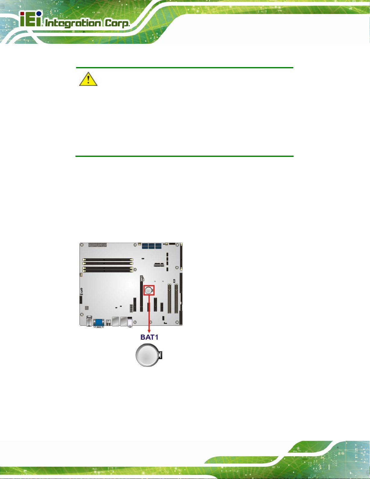
3.2.4 Battery Connector
CAUTION:
Risk of explosion if battery is replaced by an incorrect type. Only
certified engineers should replace the on-board battery.
Dispose of used batteries according to instructions and local
regulations.
CN Label: BAT1
IMBA-C2260-i2 A TX Motherboard
CN Type:
CN Location:
A system battery is placed in the battery holder. The battery provides power to the system
clock to retain the time when power is turned off.
Battery holder
Figure 3-5
See
Page 22
Figure 3-5: Battery Connector Location
Page 40

IMBA-C2260-i2 A TX Motherboard
3.2.5 Chassis Intrusion Connector
CN Label: CHASSIS1
CN Type:
CN Location:
CN Pinouts:
2-pin header
8Figure 3-6
See
Table 3-6
See
The chassis intrusion connector is for a chassis intrusion detection sensor or switch that
detects if a chassis component is removed or replaced.
Figure 3-6: Chassis Intrusion Connector Location
Pin Description
1 +3.3VSB
2 CHASSIS OPEN
Table 3-6: Chassis Intrusion Connector Pinouts
3.2.6 DDR3 DIMM Slots
CN Label: CHA_DIMM1, CHA_DIMM2, CHB_DIMM1, CHB_DIMM2
CN Type:
CN Location:
The DIMM slots are for DDR3 DIMM memory modules.
DDR3 DIMM slot
See 8Figure 3-7
Page 23
Page 41

Figure 3-7: DDR3 DIMM Slot Locations
IMBA-C2260-i2 A TX Motherboard
3.2.7 Digital I/O Connector
CN Label: DIO1
CN Type:
CN Location:
CN Pinouts:
The digital I/O connector provides programmable input and output for external devices.
The digital I/O provides 4-bit output and 4-bit input.
10-pin header
See Figure 3-8
See Table 3-7
Page 24
Figure 3-8: Digital I/O Connector Location
Page 42

IMBA-C2260-i2 A TX Motherboard
Pin Description Pin Description
1 GND 2 VCC
3 Output 3 4 Output 2
5 Output 1 6 Output 0
7 Input 3 8 Input 2
9 Input 1 10 Input 0
Table 3-7: Digital I/O Connector Pinouts
3.2.8 EC Debug Connector
CN Label: CN3
CN Type:
CN Location:
CN Pinouts:
18-pin header
Figure 3-9
See
Table 3-8
See
The EC debug connector is used for EC debug.
Figure 3-9: EC Debug Connector Location
Pin Description Pin Description
1 EC_EPP_STB# 2 EC_EPP_AFD#
3 EC_EPP_PD0 4 NC
5 EC_EPP_PD1 6 EC_EPP_INIT#
7 EC_EPP_PD2 8 EC_EPP_SLIN#
9 EC_EPP_PD3 10 GND
Page 25
Page 43

Pin Description Pin Description
11 EC_EPP_PD4 12 NC
13 EC_EPP_PD5 14 EC_EPP_BUSY
15 EC_EPP_PD6 16 EC_EPP_KSI5
17 EC_EPP_PD7 18 EC_EPP_KSI4
Table 3-8: EC Debug Connector Pinouts
3.2.9 Fan Connector (CPU)
CN Label: CPU_FAN1
IMBA-C2260-i2 A TX Motherboard
CN Type:
CN Location:
CN Pinouts:
4-pin wafer
See Figure 3-10
See Table 3-9
The fan connector attaches to a CPU cooling fan.
Figure 3-10: CPU Fan Connector Location
Pin Description
Page 26
1 GND
2 +12V
3 FANIO
4 PWM
Table 3-9: CPU Fan Connector Pinouts
Page 44

IMBA-C2260-i2 A TX Motherboard
3.2.10 Fan Connectors (System)
CN Label: SYS_FAN1, SYS_FAN2
CN Type:
CN Location:
CN Pinouts:
Each fan connector attaches to a system cooling fan.
3-pin wafer
See Figure 3-11
See Table 3-10
Figure 3-11: System Fan Connector Locations
Pin Description
1 FANIO
2 +12V (PWM)
3 GND
Table 3-10: System Fan Connector Pinouts
3.2.11 Front Panel Audio Connector
CN Label: FRONT-PANEL1
CN Type:
CN Location:
CN Pinouts:
10-pin header
Figure 3-12
See
Table 3-11
See
Page 27
Page 45
IMBA-C2260-i2 A TX Motherboard
This connector connects to speakers, a microphone and an audio input.
Figure 3-12: Front Panel Audio Connector Location
Pin Description Pin Description
1 MIC2-L 2 GND
3 MIC2-R 4 Presence#
5 LINE2-R 6 MIC2-JD
7 FRONT-IO 8 NC
9 LINE2-L 10 LINE2-JD
Table 3-11: Front Panel Audio Connector Pinouts
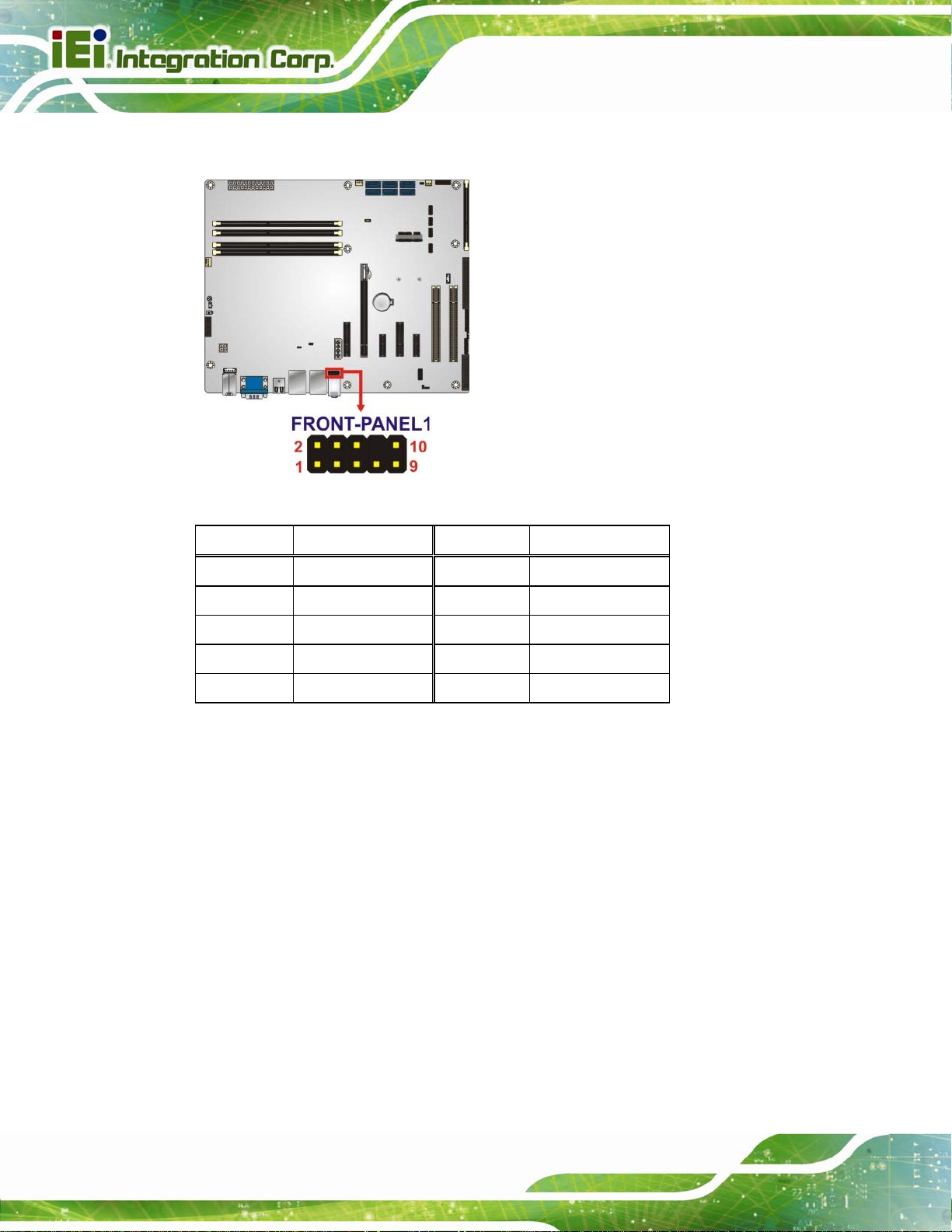
3.2.12 Front Panel Connector
CN Label: F_PANEL1
CN Type:
CN Location:
CN Pinouts:
The front panel connector connects to the indicator LEDs and buttons on the computer's
front panel.
14-pin header
See Figure 3-13
See Table 3-12
Page 28
Page 46

IMBA-C2260-i2 A TX Motherboard
Figure 3-13: Front Panel Connector Location
Function Pin Description Function Pin Description
1 +5V Speaker 2 BEEP_PWR
Power LED
Power Button
HDD LED
3 NC 4 IPMI ID_LED+
5 GND
7 PWRBTN_SW# Speaker 8 PC_BEEP
9 GND 10 NC
11 +5V 12 EXTRST13 SAT A_LED#
Table 3-12: Front Panel Connector Pinouts
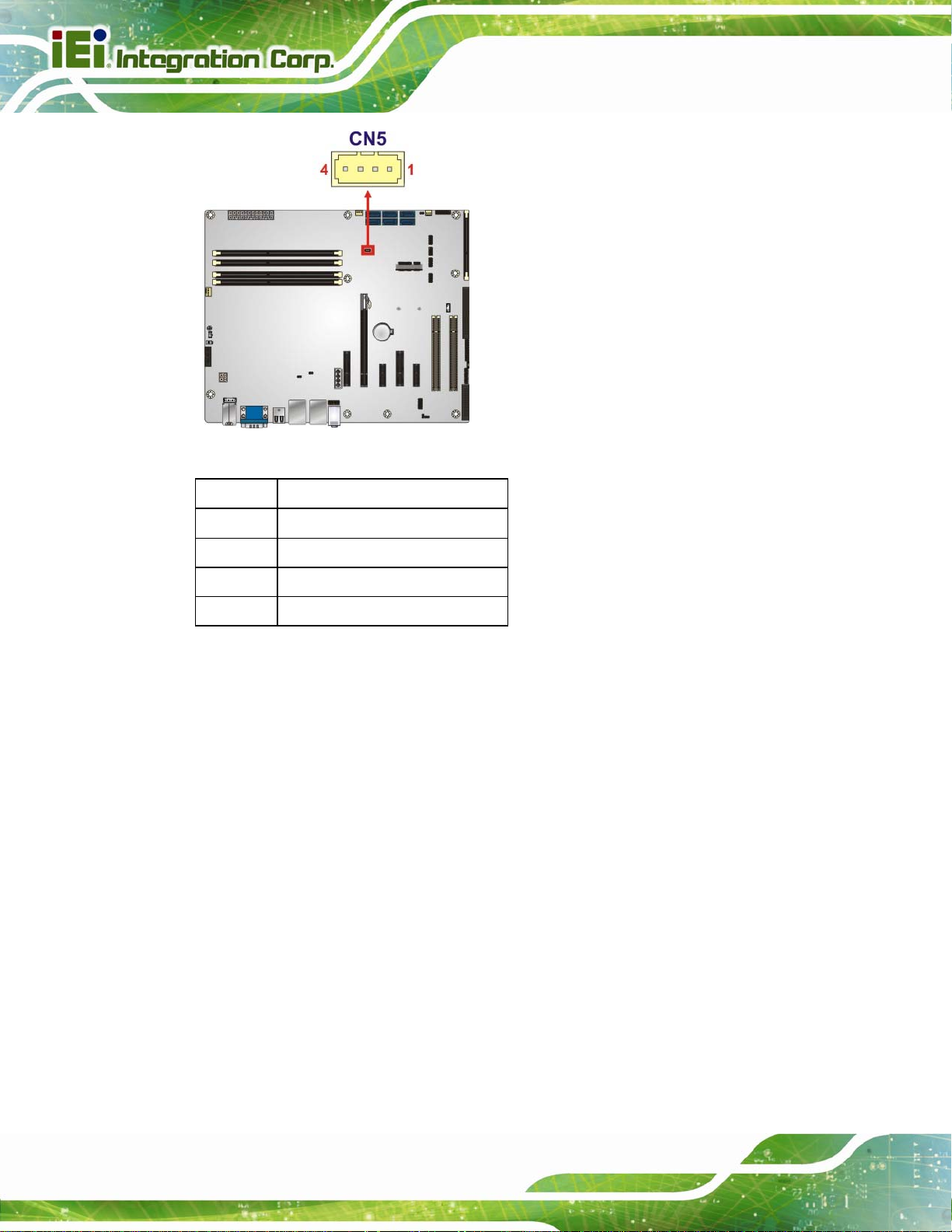
3.2.13 I2C Connector
CN Label: CN5
CN Type:
CN Location:
CN Pinouts:
2
C connector is used to connect I2C-bus devices to the mainboard.
The I
4-pin wafer
Figure 3-14
See
Table 3-13
See
IPMI LED
6 IPMI ID_LED-
Reset
14 GND
Page 29
Page 47
IMBA-C2260-i2 A TX Motherboard
Figure 3-14: I
2
C Connector Location
Pin Description
1 GND
2 PCH_GP38
3 PCH_GP39
4 +5V
Table 3-13: I2C Connector Pinouts
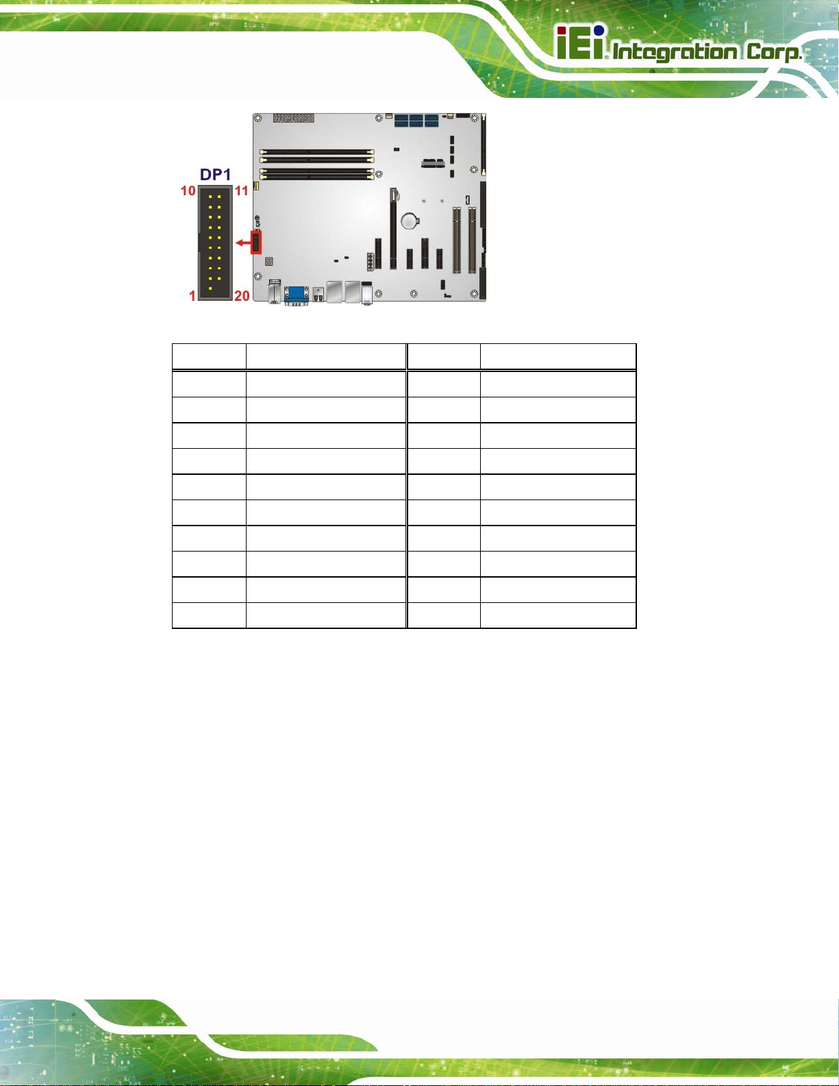
3.2.14 Internal DisplayPort Connector
CN Label: DP1
CN Type:
CN Location:
CN Pinouts:
The DisplayPort connector supports HDMI, LVDS, VGA, DVI and DisplayPort graphics
interfaces with up to 3840x2160 resolution.
19-pin box header
Figure 3-15
See
Table 3-14
See
Page 30
Page 48
IMBA-C2260-i2 A TX Motherboard
Figure 3-15: Internal DisplayPort Connector Location
Pin Description Pin Description
1 +5V 11 AUXP
2 LANE1N 12 AUXN
3 LANE1P 13 GND
4 GND 14 LANE2P
5 LANE3N 15 LANE2N
6 LANE3P 16 GND
7 GND 17 LANE0P
8 AUX_CTRL_DET_D 18 LANE0N
9 GND 19 +3.3V
10 HPD
Table 3-14: Internal DisplayPort Connector Pinouts
3.2.15 iRIS Module Slot
CN Label: IPMI1
CN Type:
CN Location:
iRIS module slot
Figure 3-16
See
The iRIS module slot allows installation of the iRIS-2400 module.
Page 31
Page 49

Figure 3-16: iRIS Module Slot Location
IMBA-C2260-i2 A TX Motherboard
WARNING:
The iRIS module slot is designed to install the iRIS-2400 module only.
DO NOT install other modules into the iRIS module slot. Doing so may
cause damage to the IMBA-C2260-i2.
3.2.16 Keyboard and Mouse Connector
CN Label: KB_MS1
CN Type:
CN Location:
CN Pinouts:
The keyboard and mouse connector connects to a PS/2 Y-cable that can be connected to
a PS/2 keyboard and mouse.
6-pin wafer
Figure 3-17
See
Table 3-15
See
Page 32
Page 50

IMBA-C2260-i2 A TX Motherboard
Figure 3-17: Keyboard and Mouse Connector Location
Pin Description
1 VCC
2 Mouse Data
3 Mouse Clock
4 Keyboard Data
5 Keyboard Clock
6 GND
Table 3-15: Keyboard and Mouse Connector Pinouts
3.2.17 LAN LED Connectors
CN Label: LED_LAN1, LED_LAN2
CN Type:
CN Location:
CN Pinouts:
The LAN LED connectors are used to connect to the LAN LED indicators on th e chassis to
indicate users the link activities of the two LAN ports.
2-pin header
8Figure 3-18
See
8Table 3-16 and Table 3-17
See
Page 33
Page 51

IMBA-C2260-i2 A TX Motherboard
Figure 3-18: LAN LED Connector Locations
Pin Description
1 +3.3V
2 LAN1_LED_LINK#_ACT
Table 3-16: LAN1 LED Connector (LED_LAN1) Pinouts
Pin Description
1 +3.3V
2 LAN2_LED_LINK#_ACT
Table 3-17: LAN2 LED Connector (LED_LAN2) Pinouts
3.2.18 mSATA Card Slot
CN Label: CN2
CN Type:
CN Location:
CN Pinouts:
The mSATA card slot is for installing mSATA cards or USB devices only
PCIe Mini slot
8Figure 3-19
See
Table 3-18
See
Page 34
Page 52

IMBA-C2260-i2 A TX Motherboard
NOTE:
If the user shorts the mSATA Slot Setup jumper (MSATA_SW1) to
force the system to enable mSATA device, the S_ATA6 connector will
be disabled. Please refer to Section
4.5.4.
Figure 3-19: mSATA Card Slot Location
Pin Description Pin Description
1
3
PCIE_WAKE#
N/C
2
4
+3.3V
GND
5
7
9
11
13
15
17
19
21
23
25
27
29
N/C
N/C
GND
MSATA_CLK#
MSATA _CLK
GND
PLTRST_N
N/C
GND
SATA_RX+
SATA_RXGND
GND
6
8
10
12
14
16
18
20
22
24
26
28
30
1.5V
N/C
N/C
N/C
N/C
N/C
GND
+3.3V
PLTRST_N
+3.3V
GND
1.5V
SMB_CLK
Page 35
Page 53

Pin Description Pin Description
IMBA-C2260-i2 A TX Motherboard
31
33
35
37
39
41
43
45
47
49
51
SATA_TXSATA_TX+
GND
GND
+3.3V
+3.3V
+3.3V
CLINK_CLK
CLINK_DATA
CLINK_RST#
MSATA_DET
Table 3-18: mSATA Card Slot Pinouts
3.2.19 Parallel Port Connector
CN Label: LPT1
32
34
36
38
40
42
44
46
48
50
52
SMB_DATA
GND
USB_DATAUSB_DATA+
GND
N/C
N/C
N/C
1.5V
GND
+3.3V
CN Type:
CN Location:
CN Pinouts:
26-pin box header
Figure 3-20
See
Table 3-19
See
The parallel port connector connects to a parallel port connector interface or some other
parallel port device such as a printer.
Page 36
Figure 3-20: Parallel Port Connector Location
Page 54

IMBA-C2260-i2 A TX Motherboard
Pin Description Pin Description
1 STROBE# 2 DATA0
3 DATA1 4 DATA2
5 DATA3 6 DATA4
7 DATA5 8 DATA6
9 DATA7 10 ACKNOWLEDGE#
11 BUSY 12 PAPER EMPTY
13 PRINTER SELECT 14 AUTO FORM FEED #
15 ERROR# 16 INITIALIZE#
17 PRINTER SELECT LN# 18 GND
19 GND 20 GND
21 GND 22 GND
23 GND 24 GND
25 GND
Table 3-19: Parallel Port Connector Pinouts
3.2.20 PCI Slots
CN Label: PCI1, PCI2
CN Type:
CN Location:
The PCI slot enables a PCI expansion module to be connected to the board.
PCI Slot
Figure 3-21
See
Figure 3-21: PCI Slot Locations
Page 37
Page 55

3.2.21 PCIe x1 Slots
CN Label: PCIEX1_1, PCIEX4_1
IMBA-C2260-i2 A TX Motherboard
CN Type:
CN Location:
The PCIe x1 slot is for PCIe x1 expansion card.
Figure 3-22: PCIe x1 Slot Locations
PCIe x1 slot
Figure 3-22
See
3.2.22 PCIe x4 Slots
CN Label: PCIEX4_2, PCIEX4_3
CN Type:
CN Location:
The PCIe x4 expansion card slots are for PCIe x4 expansion cards.
Page 38
PCIe x4 slot
Figure 3-23
See
Page 56

IMBA-C2260-i2 A TX Motherboard
Figure 3-23: PCIe x4 Slot Locations
3.2.23 PCI Express x16 Slot
CN Label: PCIEX16_1
CN Type:
CN Location:
PCIe x16 slot
Figure 3-24
See
NOTE:
The PCIe x16 interface setup is made through the BIOS menu in
“Chipset Æ PCH-IO Configuration”. Use the PEG port configuration
BIOS option to configure the PCIe x16 channel mode. Please refer to
Section
The PCIe x16 expansion card slot is for PCIe x16 expansion card.
5.4.1 for detailed information.
Page 39
Page 57

Figure 3-24: PCIe x16 Slot Location
IMBA-C2260-i2 A TX Motherboard
3.2.24 Power Button
CN Label: PWR_SW1
CN Type:
CN Location:
The on-board power button controls system power.
Figure 3-25: Power Button Location
Push button
Figure 3-25
See
Page 40
Page 58

IMBA-C2260-i2 A TX Motherboard
3.2.25 SATA 6Gb/s Drive Connector
CN Label: S_ATA1, S_ATA2, S_ATA3, S_ATA4, S_ATA5, S_ATA6
CN Type:
CN Location:
CN Pinouts:
7-pin SATA drive connector
See Figure 3-26
See Table 3-20
The SATA drive connectors can be connected to SATA drives and support up to 6Gb/s
data transfer rate.
Figure 3-26: SATA 6Gb/s Drive Connector Location
Pin Description
1 GND
2 SATA_TX+
3 SATA_TX4 GND
5 SATA_RX6 SATA RX+
7 GND
Table 3-20: SATA 6Gb/s Drive Connector Pinouts
Page 41
Page 59

IMBA-C2260-i2 A TX Motherboard
NOTE:
If the user shorts the mSATA Slot Setup jumper (MSATA_SW1) to
force the system to enable mSATA device, the S_ATA6 connector will
be disabled. Please refer to Section
3.2.26 Serial Port Connector, RS-232
CN Label: COM2-6
CN Type:
CN Location:
CN Pinouts:
The connector provides four RS-232 ports connection.
40-pin box header
See Figure 3-27
See Table 3-21
4.5.4.
Page 42
Figure 3-27: RS-232 Serial Port Connector Location
Pin Description Pin Description
1 DCD 2 DSR
3 RXD 4 RTS
COM2 5 TXD 6 CTS
7 DTR 8 RI
9 GND 10 GND
Page 60
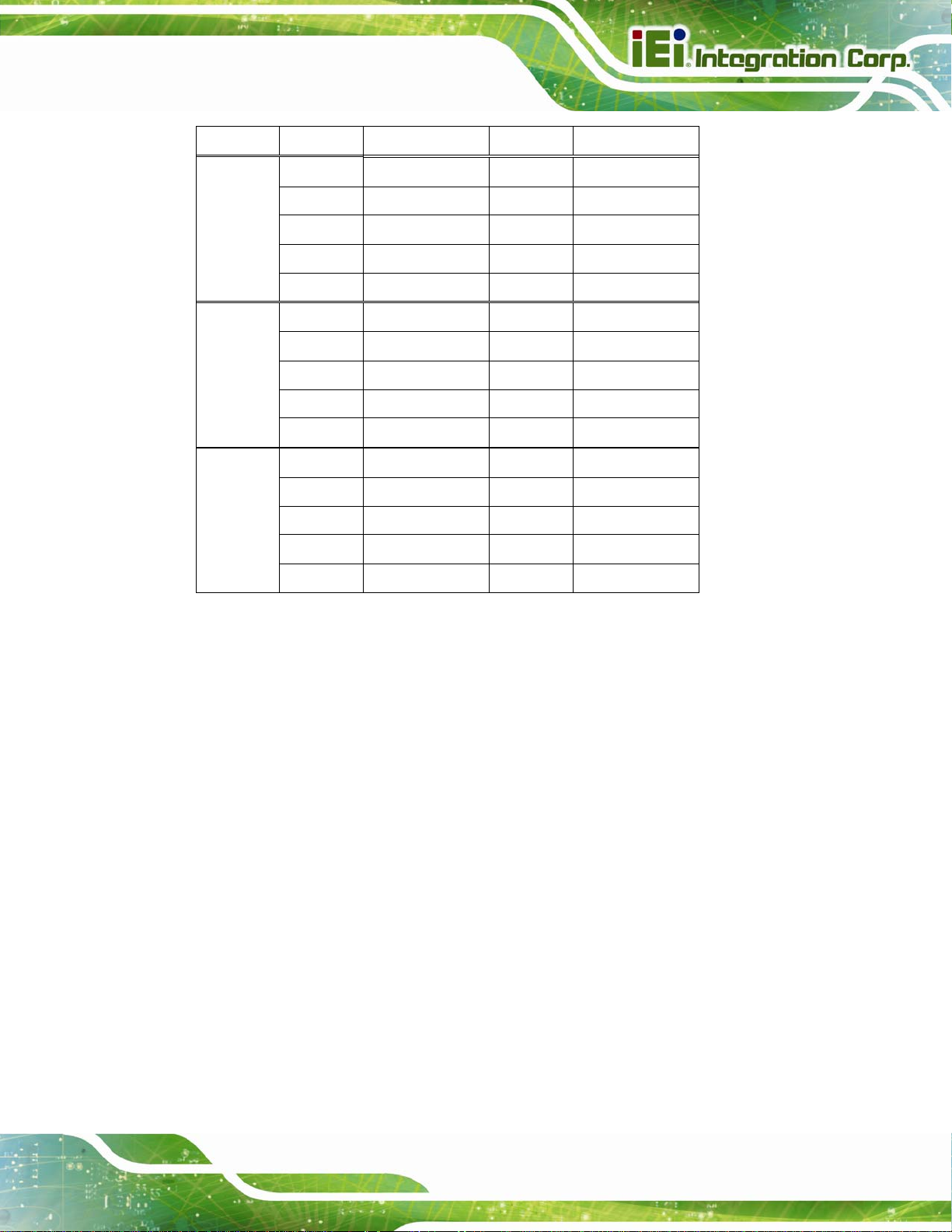
IMBA-C2260-i2 A TX Motherboard
Pin Description Pin Description
11 DCD 12 DSR
13 RXD 14 RTS
COM3 15 TXD 16 CTS
17 DTR 18 RI
19 GND 20 GND
21 DCD 22 DSR
23 RXD 24 RTS
COM5 25 TXD 26 CTS
27 DTR 28 RI
29 GND 30 GND
31 DCD 32 DSR
33 RXD 34 RTS
COM6 35 TXD 36 CTS
37 DTR 38 RI
39 GND 40 GND
Table 3-21: RS-232 Serial Port Connector Pinouts
3.2.27 Serial Port Connector, RS-422/485
CN Label: COM4
CN Type:
CN Location:
CN Pinouts:
This connector provides RS-422 or RS-485 communications.
4-pin wafer
See Figure 3-28
See Table 3-22
Page 43
Page 61
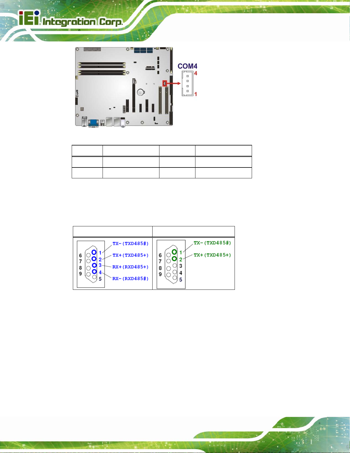
IMBA-C2260-i2 A TX Motherboard
Figure 3-28: RS-422/485 Connector Location
Pin Description Pin Description
1 RXD422- 3 TXD422+/TXD485+
2 RXD422+ 4 TXD422-/TXD485-
Table 3-22: RS-422/485 Connector Pinouts
Use the optional RS-422/485 cable to connect to a serial device. The pinouts of the DB-9
connector are listed below.
RS-422 Pinouts RS-485 Pinouts
Table 3-23: DB-9 RS-422/485 Pinouts
3.2.28 SMBus Connector
CN Label: CN1
CN Type:
CN Location:
4-pin wafer
Figure 3-29
See
Table 3-24
CN Pinouts:
See
The SMBus (System Management Bus) connector provides low-speed system
management communications.
Page 44
Page 62

IMBA-C2260-i2 A TX Motherboard
Figure 3-29: SMBus Connector Location
Pin Description
1 GND
2 SMB_DATA
3 SMB_CLK
4 +5V
Table 3-24: SMBus Connector Pinouts
3.2.29 SPI Flash Connector
CN Label: JSPI1
CN Type:
CN Location:
CN Pinouts:
The SPI flash connector is used to flash the SPI ROM.
8-pin header
See Figure 3-30
See Table 3-25
Figure 3-30: SPI Flash Connector Location
Page 45
Page 63

Pin Description Pin Description
1 +3.3V 2 SPI_CS#
3 SPI_SO 4 NC
5 GND 6 SPI_CLK
7 SPI_SI 8 NC
Table 3-25: SPI Flash Connector Pinouts
3.2.30 SPI Flash Connector, EC
CN Label: JSPI2
IMBA-C2260-i2 A TX Motherboard
CN Type:
CN Location:
CN Pinouts:
8-pin header
See Figure 3-31
See Table 3-26
The SPI flash connector is used to flash the EC ROM.
Figure 3-31: SPI EC Flash Connector Location
Pin Description Pin Description
Page 46
1 +3.3V 2 SPI_CS#
3 SPI_SO 4 NC
5 GND 6 SPI_CLK
7 SPI_SI 8 NC
Table 3-26: SPI EC Flash Connector Pinouts
Page 64

IMBA-C2260-i2 A TX Motherboard
3.2.31 TPM Connector
CN Label: TPM1
CN Type:
CN Location:
CN Pinouts:
20-pin header
See Figure 3-32
See Table 3-27
The TPM connector connects to a TPM module.
Figure 3-32: TPM Connector Location
Pin Description Pin Description
1 LCLK 2 GND
3 LFRAME# 4 KEY
5 LRERST# 6 +5V
7 LAD3 8 LAD2
9 +3.3V 10 LAD1
11 LAD0 12 GND
13 SCL 14 SDA
15 SB3V 16 SERIRQ
17 GND 18 GLKRUN#
19 LPCPD# 20 LDRQ#
Table 3-27: TPM Connector Pinouts
Page 47
Page 65

3.2.32 USB 2.0 Connectors
CN Label: USB1, USB2
IMBA-C2260-i2 A TX Motherboard
CN Type:
CN Location:
CN Pinouts:
The USB 2.0 connectors connect to USB 2.0 devices. Each pin header provides two USB
2.0 ports.
8-pin header
See Figure 3-33
See Table 3-28
Page 48
Figure 3-33: USB 2.0 Connector Pinout Locations
Pin Description Pin Description
1 VCC 2 GND
3 USB_DATA- 4 USB_DATA+
5 USB_DATA+ 6 USB_DATA7 GND 8 VCC
Table 3-28: USB 2.0 Connector Pinouts
Page 66

IMBA-C2260-i2 A TX Motherboard
3.3 External Peripheral Interface Connector Panel
The figure below shows the external peripheral interface connector (EPIC) panel. The
EPIC panel consists of the following:
Figure 3-34: External Peripheral Interface Connector
3.3.1 Audio Connector
CN Label: AUDIO_CV1
CN Type:
CN Location:
The audio jacks connect to external audio devices.
Line In port (Light Blue): Connects a CD-ROM, DVD player, or other audio
devices.
Line Out port (Lime): Connects to a head phone or a speaker. With
multi-channel configurations, this port can also connect to front speakers.
Microphone (Pink): Connects a microphone.
Audio jack
See Figure 3-34
Page 49
Page 67

Figure 3-35: Audio Connector
3.3.2 Ethernet and USB 3.0 Connectors
CN Label: LAN1_USB1, LAN1_USB2
IMBA-C2260-i2 A TX Motherboard
CN Type:
CN Location:
CN Pinouts:
RJ-45, USB 3.0
See Figure 3-34
See Table 3-29 and Table 3-30
There are four external USB 3.0 connectors on the IMBA-C2260-i2.
Pin Description Pin Description
1 VCC 10 VCC
2 USB_DATA- 11 USB_DATA3 USB_DATA+ 12 USB_ DATA+
4 GND 13 GND
5 USB3_RX- 14 USB3_RX6 USB3_RX+ 15 USB3_ RX+
7 GND 16 GND
8 USB3_TX- 17 USB3_TX9 USB3_TX+ 18 USB3_TX+
Page 50
Table 3-29: USB 3.0 Port Pinouts
Each LAN connector connects to a local network
Page 68

IMBA-C2260-i2 A TX Motherboard
Pin Description Pin Description
20 LAN1_MDI0P 24 LAN1_MDI2P
21 LAN1_MDI0N 25 LAN1_MDI2N
22 LAN1_MDI1P 26 LAN1_MDI3P
23 LAN1_MDI1N 27 LAN1_MDI3N
Table 3-30: LAN Pinouts
3.3.3 Keyboard/Mouse and USB 2.0 Connectors
CN Label: K/M_USB1
CN Type:
CN Location:
CN Pinouts:
PS/2, USB 2.0
See Figure 3-34
See Table 3-31 and Table 3-32
The USB 2.0 connector can be connected to a USB device.
Pin Description Pin Description
1 VCC 5 VCC
2 USB_DATA- 6 USB_DATA3 USB_DATA+ 7 USB_DATA+
4 GND 8 GND
Table 3-31: USB 2.0 Port Pinouts
The PS/2 port is for connecting a PS/2 mouse and a PS/2 keyboard.
Pin Description
9 GND
10 Ke yboard Data
11 Mouse Data
12 VCC
13 Keyboard Clock
14 Mouse Clock
Table 3-32: PS/2 Connector Pinouts
Page 51
Page 69

3.3.4 Serial Port and VGA Connector
CN Label: VGACOM1
IMBA-C2260-i2 A TX Motherboard
CN Type:
CN Location:
CN Pinouts:
DB-9 and 15-pin VGA connector
See Figure 3-34
See Table 3-33
The serial port connects to a RS-232 serial communications device.
Pin Description Pin Description
1 DCD1 6 DSR1
2 RXD1 7 RTS1
3 TXD1 8 CTS1
4 DTR1 9 RI1
5 GND
Table 3-33: Serial Port Connector Pinouts
Page 52
Figure 3-36: Serial Port Connector Pinouts
The 15-pin VGA connector connects to a monitor that accepts a standard VGA input.
Pin Description Pin Description
1 RED 2 GREEN
3 BLUE 4 NC
5 GND 6 GND
7 GND 8 GND
9 VCC 10 GND
11 NC 12 DDCDA
Page 70

IMBA-C2260-i2 A TX Motherboard
Pin Description Pin Description
13 HSYNC 14 VSYNC
15 DDCCLK
Table 3-34: VGA Connector Pinouts
Figure 3-37: VGA Connector
3.3.5 USB 2.0 Connectors
CN Label: CNUSB1
CN Type:
CN Location:
CN Pinouts:
Each USB 2.0 connector can be connected to a USB 2.0 device.
USB 2.0
See Figure 3-34
See Table 3-35
Pin Description Pin Description
1 VCC 5 VCC
2 USB_DATA- 6 USB_DATA3 USB_DATA+ 7 USB_DATA+
4 GND 8 GND
Table 3-35: USB 2.0 Port Pinouts
Page 53
Page 71

IMBA-C2260-i2 A TX Motherboard
Chapter
4
4 Installation
Page 54
Page 72

IMBA-C2260-i2 A TX Motherboard
4.1 Anti-static Precautions
WARNING:
Failure to take ESD precautions during the installation of the
IMBA-C2260-i2 may result in permanent damage to the
IMBA-C2260-i2 and severe injury to the user.
Electrostatic discharge (ESD) can cause serious damage to electronic components,
including the IMBA-C2260-i2. Dry climates are especially susceptible to ESD. It is
therefore critical that whenever the IMBA-C2260-i2 or any other electrical component is
handled, the following anti-static precautions are strictly adhered to.
Wear an anti-static wristband: - Wearing a simple anti-static wristband can
help to prevent ESD from damaging the board.
Self-grounding:- Before handling the board touch any grounded conducting
material. During the time the board is handled, frequently touch any
conducting materials that are connected to the ground.
Use an anti-static pad: When configuring the IMBA-C2260-i2, place it on an
antic-static pad. This reduces the possibility of ESD damaging the
IMBA-C2260-i2.
Only handle the edges of the PCB:-: When handling the PCB, hold the PCB
by the edges.
4.2 Installation Considerations
NOTE:
The following installation notices and installation considerations should
be read and understood before installation. All installation notices must
be strictly adhered to. Failing to adhere to these precautions may lead
to severe damage and injury to the person performing the installation.
Page 55
Page 73

IMBA-C2260-i2 A TX Motherboard
WARNING:
The installation instructions described in this manual should be
carefully followed in order to prevent damage to the components and
injury to the user.
Before and during the installation please DO the following:
Read the user manual:
o The user manual provides a complete description of the IMBA-C2260-i2
installation instructions and configuration options.
Wear an electrostatic discharge cuff (ESD):
o Electronic components are easily damaged by ESD. Wearing an ESD cuff
removes ESD from the body and helps prevent ESD damage.
Place the IMBA-C2260-i2 on an antistatic pad:
o When installing or configuring the motherboard, place it on an antistatic
pad. This helps to prevent potential ESD damage.
Turn all power to the IMBA-C2260-i2 of f:
o When working with the IMBA-C2260-i2, make sure that it is disconnected
from all power supplies and that no electricity is being fed into the system.
Before and during the installation of the IMBA-C2260-i2, DO NOT:
Remove any of the stickers on the PCB board. These stickers are required for
warranty validation.
Use the product before verifying all the cables and power connectors are
properly connected.
Allow screws to come in contact with the PCB circuit, connector pins, or its
components.
Page 56
Page 74

IMBA-C2260-i2 A TX Motherboard
4.2.1 Socket LGA1150 CPU Installation
WARNING:
CPUs are expensive and sensitive components. When installing the
CPU please be careful not to damage it in anyway. Make sure the CPU
is installed properly and ensure the correct cooling kit is properly
installed.
DO NOT touch the pins at the bottom of the CPU. When handling the
CPU, only hold it on the sides.
To install the CPU, follow the steps below.
Step 1: Disengage the load lever by pressing the lever down and slightly outward to
clear the retention tab. Fully open the lever. See
Figure 4-1: Disengage the CPU Socket Load Lever
Step 2: Open the socket and remove the protective cover. The black protective
Figure 4-1.
cover can be removed by pulling up on the tab labeled "Remove". See
Figure 4-2.
Page 57
Page 75
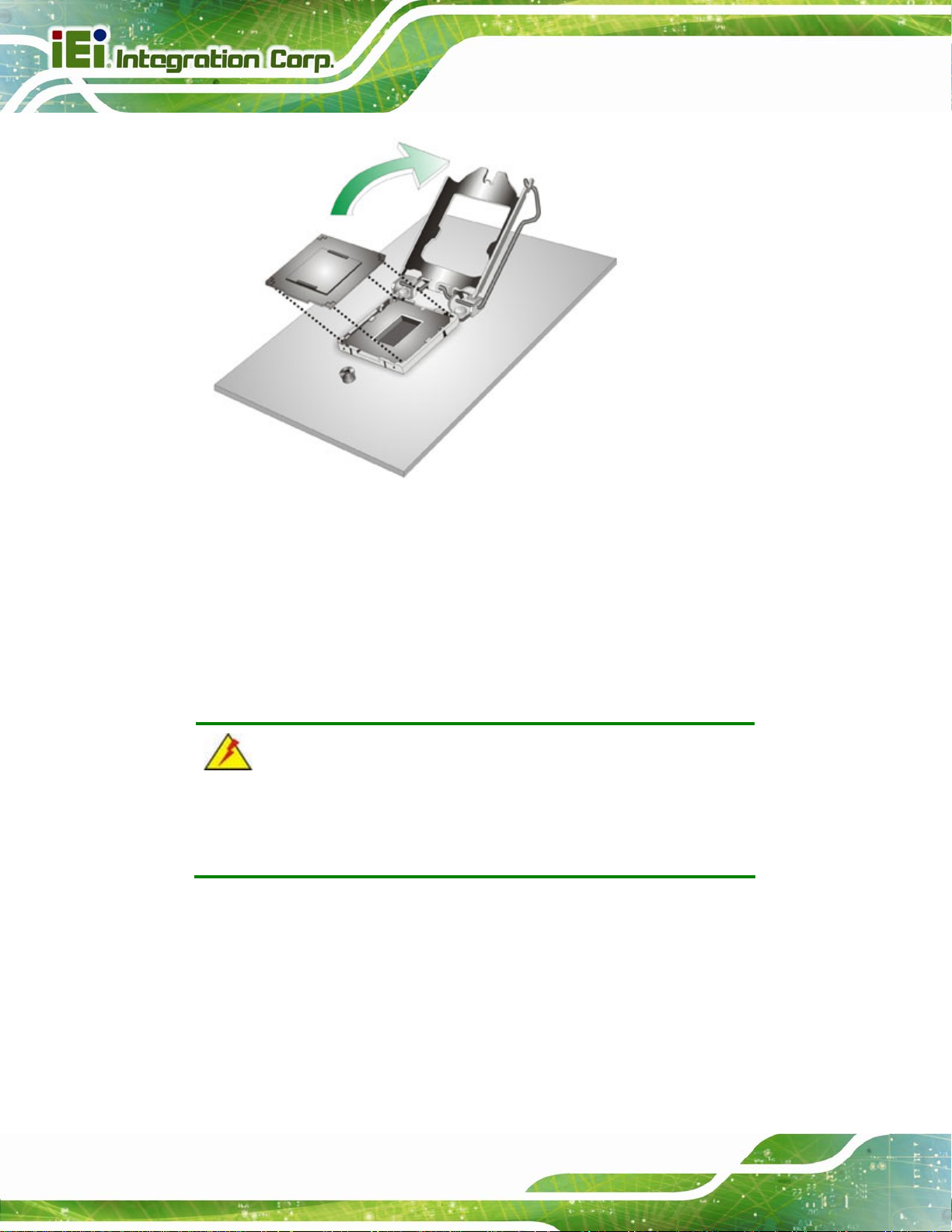
Figure 4-2: Remove Protective Cover
IMBA-C2260-i2 A TX Motherboard
Step 3: Inspect the CPU socket. Make sure there are no bent pins and make sure the
socket contacts are free of foreign material. If any debris is found, remove it with
compressed air.
Step 4: Orientate the CPU properly. The contact array should be facing the CPU
socket.
WARNING:
DO NOT touch the pins at the bottom of the CPU. When handling the
CPU, only hold it on the sides.
Step 5: Correctly position the CPU. Match the Pin 1 mark with the cut edge on the
CPU socket.
Step 6: Align the CPU pins. Locate pin 1 and the two orientation notches on the CPU.
Page 58
Carefully match the two orientation notches on the CPU with the socket
alignment keys.
Page 76

IMBA-C2260-i2 A TX Motherboard
Step 7: Insert the CPU. Gently insert the CPU into the socket. If the CPU pins are
properly aligned, the CPU should slide into the CPU socket smoothly. See
Figure 4-3.
Figure 4-3: Insert the Socket LGA1150 CPU
Step 8: Close the CPU socket. Close the load plate and pull the load lever back a little
to have the load plate be able to secure to the knob. Engage the load lever by
pushing it back to its original position (
resistance, but will not require extreme pressure.
Figure 4-4). There will be some
Figure 4-4: Close the Socket LGA1150
Page 59
Page 77

Step 9: Connect the 12 V power to the board. Connect the 12 V power from the power
supply to the board. Step 0:
4.2.2 Socket LGA1150 Cooling Kit Installation
WARNING:
DO NOT attempt to install a push-pin cooling fan.
The pre-installed support bracket prevents the board from
bending and is ONLY compatible with captive screw type cooling
fans.
IMBA-C2260-i2 A TX Motherboard
The cooling kit can be bought from IEI. The cooling kit has a heat sink and fan.
WARNING:
Do not wipe off (accidentally or otherwise) the pre-sprayed layer of
thermal paste on the bottom of the heat sink. The thermal paste
between the CPU and the heat sink is important for optimum heat
dissipation.
To install the cooling kit, follow the instructions below.
Step 1: A cooling kit bracket is pre-inst alled on the rear of the motherboard. See
4-5.
Figure
Page 60
Page 78

IMBA-C2260-i2 A TX Motherboard
Figure 4-5: Cooling Kit Support Bracket
Step 2: Place the cooling kit onto the socket LGA1150 CP U. Make sure the CPU
cable can be properly routed when the cooling kit is installed.
Step 3: Mount the cooling kit. Gently place the cooling kit on top of the CPU. Make
sure the four threaded screws on the corners of the cooling kit properly pass
through the holes of the cooling kit bracket.
Step 4: Secure the cooling kit by fastening the four retention screws of the cooling kit.
Step 5: Connect the fan cable. Connect the cooling kit fan cable to the CPU fan
connector on the IMBA-C2260-i2. Carefully route the cable and avoid heat
generating chips and fan blades.Step 0:
Page 61
Page 79
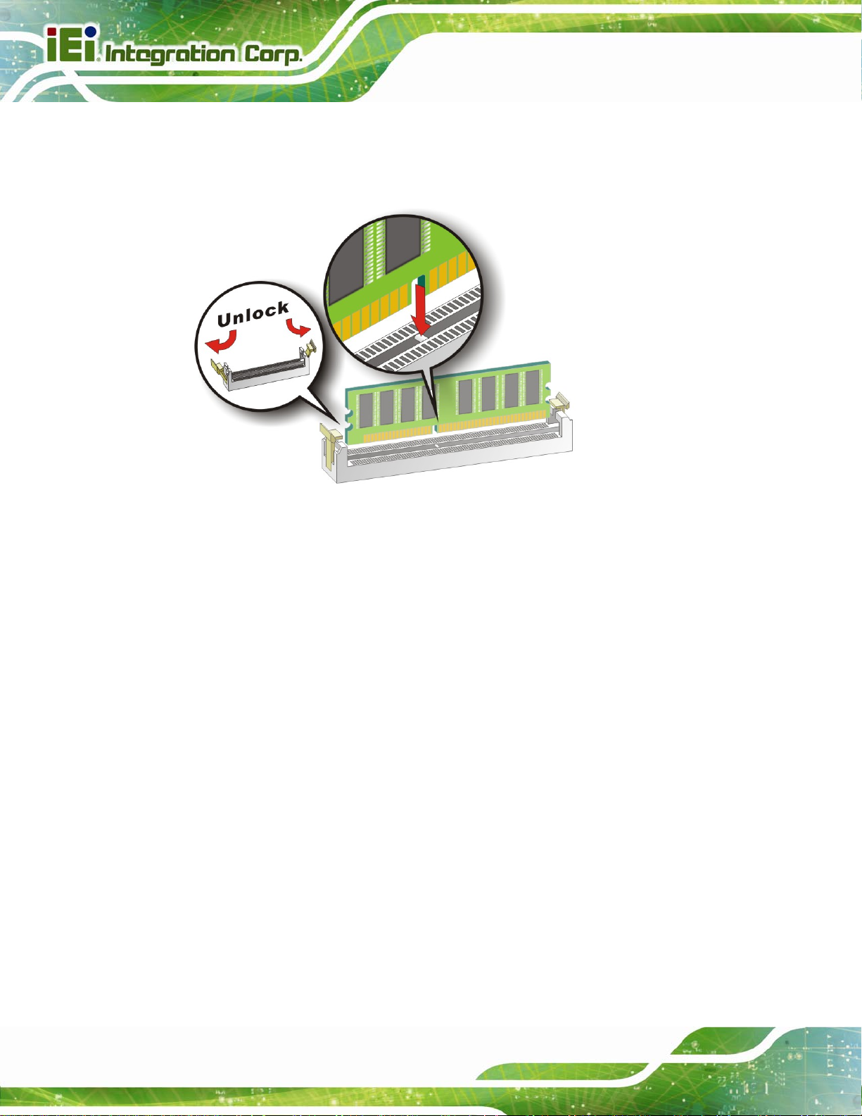
4.2.3 DIMM Installation
To install a DIMM, please follow the steps below and refer to Figure 4-6.
IMBA-C2260-i2 A TX Motherboard
Figure 4-6: DIMM Installation
Step 1: Open the DIMM socket handles. Open the two handles outwards as far as
they can. See
Step 2: Align the DIMM with the socket. Align the DIMM so the notch on the memory
lines up with the notch on the memory socket. See
Step 3: Insert the DIMM. Once aligned, press down until the DIMM is properly seated.
Clip the two handles into place. See
Step 4: Removing a DIMM. To remove a DIMM, push both handles outward. The
memory module is ejected by a mechanism in the socket.Step 0:
Figure 4-6.
Figure 4-6.
Figure 4-6.
Page 62
Page 80

IMBA-C2260-i2 A TX Motherboard
4.3 iRIS Module Installation
WARNING:
The iRIS module slot is designed to install the iRIS-2400 module only.
DO NOT install other modules into the iRIS module slot. Doing so may
cause damage to the IMBA-C2260-i2.
To install the iRIS-2400 module, please follow the steps below and refer to Figure 4-7.
Figure 4-7: iRIS Module Installation
Step 1: Locate the iRIS module slot. See
Step 2: Open the socket handles. Open the two handles outwards as far as they can.
Figure 4-7.
See
Step 3: Align the iRIS-2400 module with the socket. Align the iRIS-2400 module so
the notch on the module lines up with the notch on the socket. See
Step 4: Insert the iRIS-2400 module. Once aligned, press down until the iRIS-2400
module is properly seated. Clip the two handles into place. See
Figure 3-16.
Figure 4-7.
Figure 4-7.
Page 63
Page 81

IMBA-C2260-i2 A TX Motherboard
Step 5: Removing the iRIS-2400 module. To remove the iRIS-2400 module, push both
handles outward. The module is ejected by a mechanism in the socket.Step 0:
NOTE:
After installing the iRIS-2400 module, use LAN1_USB2 port to
establish a network connection. Please refer to Section
setup procedures.
4.4 mSATA Card Installation
To install an mSATA card, please follow the steps below.
Step 1: Locate the mSA TA card slot. The location of the mSATA card slot is shown in
Chapter 3.
Step 2: Remove the retention screws. Remove the two retention screws secured on
the motherboard as shown in
4.9 for IPMI
9Figure 4-8.
Page 64
Figure 4-8: Remove the Retention Screws for the mSATA Card
Step 3: Insert into the socket at an angle. Line up the notch on the card with the notch
on the connector. Slide the mSATA card into the socket at an angle of about 20º
9Figure 4-9).
(
Page 82

IMBA-C2260-i2 A TX Motherboard
Figure 4-9: Insert the mSATA Card into the Socket at an Angle
Step 4: Secure the mSATA card. Secure the mSATA card with the retention screws
previously removed (
9Figure 4-10). Step 0:
Figure 4-10: Secure the mSATA Card
Page 65
Page 83

4.5 System Configuration
The system configuration should be performed before installation.
4.5.1 AT/ATX Power Mode Setting
The AT and ATX power mode selection is made through the AT/ATX power mode switch
IMBA-C2260-i2 A TX Motherboard
which is shown in
Figure 4-11: AT/ATX Power Mode Switch Location
Figure 4-11.
Setting Description
1-2 ATX power mode (default)
2-3 AT power mode
Table 4-1: AT/ATX Power Mode Switch Settings
4.5.2 Clear CMOS Button
To reset the BIOS, remove the on-board battery and press the clear CMOS button for
three seconds or more. The clear CMOS button location is shown in
Page 66
Figure 4-12.
Page 84

IMBA-C2260-i2 A TX Motherboard
Figure 4-12: Clear CMOS Button Location
4.5.3 Flash Descriptor Security Override
The Flash Descriptor Security Override jumper specifies whether to override the flash
descriptor.
Setting Description
Short 1-2 No override (default)
Short 2-3 Override
Table 4-2: Flash Descriptor Security Override Jumper Settings
Figure 4-13: Flash Descriptor Security Override Jumper Location
Page 67
Page 85

4.5.4 mSATA Slot Setup
The mSATA Slot Setup jumper specifies whether to automatically detect the mSATA
device installed in the mSATA card slot (CN2). If the user shorts the mSATA Slot Setup
jumper to force the system to enable mSATA device, the S_ATA6 connector will be
disabled.
Setting Description
Open Automatically detect mSATA device (Default)
IMBA-C2260-i2 A TX Motherboard
Short 1-2
Table 4-3: mSATA Slot Setup Jumper Settings
Force to enable mSATA device
(The S_ATA6 conne ctor will be disabled)
Figure 4-14: mSATA Slot Setup Jumper Location
4.5.5 PCIe x16 Interface Setup
The PCIe x16 interface setup is made through the BIOS menu in “Chipset Æ PCH-IO
Configuration”. Use the PEG port configuration BIOS option to configure the PCIe x16
channel mode.
Page 68
Page 86

IMBA-C2260-i2 A TX Motherboard
Options Description
1 x16 PCIE Sets the PCIe x16 slot as one PCIe x16
2 x8 PCIE Sets the PCIe x16 slot as two PCIe x8
1 x8, 2 x4 PCIE Sets the PCIe x16 slot as one PCIe x8 or two PCIe x4 (default)
Table 4-4: PCIe x16 Interface Setup
NOTE:
When setting to 1 x16 PCIE option, the PCIEX4_2 and PCIEX4_3 slots
will be disabled.
Please refer to Section 5.4.1 for detailed information.
4.5.6 USB Power Selection
The USB power selection is made through the BIOS menu in “Chipset Æ PCH-IO
Configuration”. Use the USB Power SW1 and the USB Power SW2 BIOS options to
configure the correspondent USB ports (see
the USB power source.
BIOS Options Configured USB Ports
Table 4-5) and refer to Table 4-6 to select
USB Power SW1
USB Power SW2
K/M_USB1 (external USB 2.0 ports)
LAN1_USB1 (external USB 3.0 ports)
USB1 (internal USB 2.0 ports)
USB2 (internal USB 2.0 ports)
LAN1_USB2 (external USB 3.0 ports)
Table 4-5: BIOS Options and Configured USB Ports
Options Description
+5V DUAL +5V dual (default)
+5V +5V
Table 4-6: USB Power Source Setup
Please refer to Section 5.4.1 for detailed information.
Page 69
Page 87

IMBA-C2260-i2 A TX Motherboard
4.6 Internal Peripheral Device Connections
This section outlines the installation of peripheral devices to the onboard connectors.
4.6.1 SATA Drive Connection
The IMBA-C2260-i2 is shipped with two SATA drive cables. To connect the SATA drives
to the connectors, please follow the steps below.
Step 1: Locate the connectors. The locations of the SATA drive connectors are shown
in Chapter 3.
Step 2: Insert the cable connector. Insert the cable connector into the on-board SATA
drive connector until it clips into place. See
Figure 4-15.
Page 70
Figure 4-15: SATA Drive Cable Connection
Step 3: Connect the cable to the SATA disk. Connect the connector on the other end
of the cable to the connector at the back of the SATA drive. See
Step 4: Connect the SATA power cable. Connect the SATA power connector to the
back of the SATA drive. See
Figure 4-16. Step 0:
Figure 4-16.
Page 88

IMBA-C2260-i2 A TX Motherboard
Figure 4-16: SATA Power Drive Connection
The SATA power cable can be bought from IEI. See
Optional Items in Section 2.4.
4.7 External Peripheral Interface Connection
This section describes connecting devices to the external connectors on the
IMBA-C2260-i2.
4.7.1 Audio Connector
The audio jacks on the external audio connector enable the IMBA-C2260-i2 to be
connected to a stereo sound setup. Each jack supports both input and output. When
connecting a device, the High Definition Audio utility will automatically detect input or
output. The lime green audio jack does not support input from a microphone. To install the
audio devices, follow the steps below.
Step 1: Identify the audio plugs. The plugs on your home theater system or speakers
may not match the colors on the rear panel.
Page 71
Page 89

Step 2: Plug the audio plugs into the audio jacks. Plug the audio plugs into the audio
jacks. If the plugs on your speakers are different, an adapter will need to be used
to plug them into the audio jacks.
IMBA-C2260-i2 A TX Motherboard
Figure 4-17: Audio Connector
Step 3: Check audio clarity. Check that the sound is coming through the right speakers
by adjusting the balance front to rear and left to right. Step 0:
4.7.2 LAN Connection
There are two external RJ-45 LAN connectors. The RJ-45 connectors enable connection
to an external network. To connect a LAN cable with an RJ-45 connector, please follow
the instructions below.
Step 1: Locate the RJ-45 connectors. The locations of the USB connectors are shown
in Chapter 3.
Step 2: Align the connectors. Align the RJ-45 connector on the LAN cable with one of
the RJ-45 connectors on the IMBA-C2260-i2. See
Figure 4-18.
Page 72
Page 90

IMBA-C2260-i2 A TX Motherboard
Figure 4-18: LAN Connection
Step 3: Insert the LAN cable RJ-45 connector. Once aligned, gently insert the LAN
cable RJ-45 connector into the on-board RJ-45 connector. Step 0:
4.7.3 PS/2 Keyboard and Mouse Connection
The IMBA-C2260-i2 has a PS/2 connector on the external peripheral interface panel. The
PS/2 connector is used to connect to a keyboard or a mouse to the system. Follow the
steps below to connect a keyboard or a mouse to the IMBA-C2260-i2.
Step 1: Locate the PS/2 connector. The location of the PS/2 connector is shown in
Chapter 3.
Step 2: Insert the keyboard/mouse connector. Insert a PS/2 keyboard or mouse
connector into the PS/2 connector on the external peripheral interface connector .
Figure 4-19.
See
Page 73
Page 91

Figure 4-19: PS/2 Keyboard/Mouse Connector
IMBA-C2260-i2 A TX Motherboard
4.7.4 Serial Device Connection
The IMBA-C2260-i2 has a single female DB-9 connector on the external peripheral
interface panel for a serial device. Follow the steps below to connect a serial device to the
IMBA-C2260-i2.
Step 1: Locate the DB-9 connector. The location of the DB-9 connector is shown in
Chapter 3.
Step 2: Insert the serial connector. Insert the DB-9 connector of a serial device into
the DB-9 connector on the external peripheral interface. See
Figure 4-20.
Page 74
Page 92

IMBA-C2260-i2 A TX Motherboard
Figure 4-20: Serial Device Connector
Step 3: Secure the connector. Secure the serial device connector to the external
interface by tightening the two retention screws on either side of the connector.
4.7.5 USB Device Connection
The external USB Series "A" receptacle connectors provide easier and quicker access to
external USB devices. Follow the steps below to connect USB devices to the
IMBA-C2260-i2.
Step 1: Locate the USB Series "A" receptacle connectors. The locations of the USB
Series "A" receptacle connectors are shown in Chapter 3.
Step 2: Insert a USB Series "A" plug. Insert the USB Series "A" plug of a device into
the USB Series "A" receptacle on the external peripheral interface. See
Figure 4-21. Step 0:
Step 0:
Page 75
Page 93

Figure 4-21: USB Device Connection
IMBA-C2260-i2 A TX Motherboard
4.7.6 VGA Monitor Connection
The IMBA-C2260-i2 has a single female DB-15 connector on the external peripheral
interface panel. The DB-15 connector is connected to a CRT or VGA monitor. To connect
a monitor to the IMBA-C2260-i2, please follow the instructions below.
Step 1: Locate the female DB-15 connector. The location of the female DB-15
connector is shown in Chapter 3.
Step 2: Align the VGA connector. Align the male DB-15 connector on the VGA screen
cable with the female DB-15 connector on the external peripheral interface.
Step 3: Insert the VGA connector. Once the connectors are properly ali gned with the
insert the male connector from the VGA screen into the female connector on the
IMBA-C2260-i2. See
Figure 4-22.
Page 76
Page 94
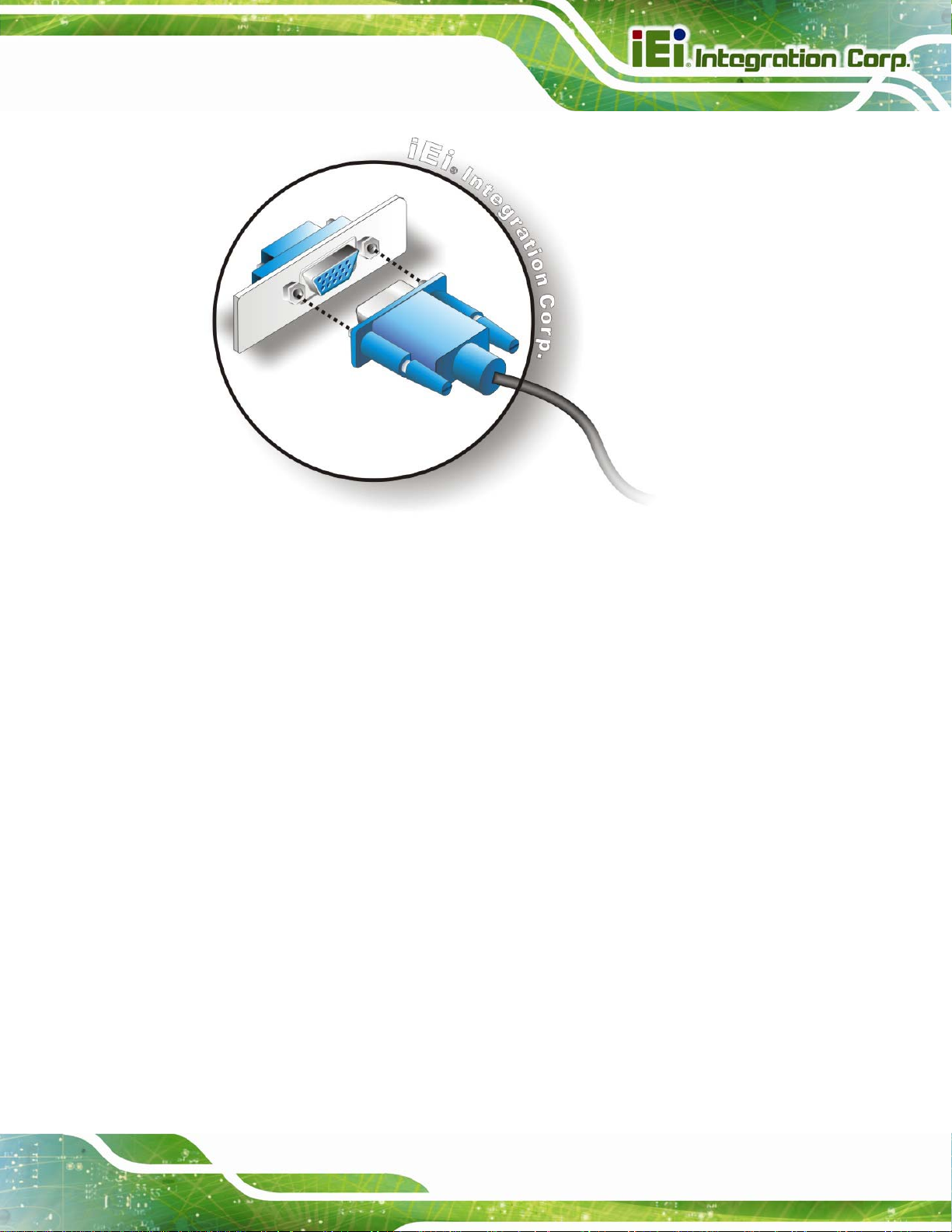
IMBA-C2260-i2 A TX Motherboard
Figure 4-22: VGA Connector
Step 4: Secure the connector. Secure the DB-15 VGA connector from the VGA
monitor to the external interface by tightening the two retention screws on either
side of the connector. Step 0:
4.8 Intel® AMT Setup Procedure
The IMBA-C2260-i2 is featured with the Intel® Active Management Technology (AMT). To
enable the Intel® AMT function, follow the steps below.
Step 1: Make sure at least one of the memory sockets is installed with a DDR3 DIMM.
Step 2: Connect an Ethernet cable to the RJ-45 connector labeled LAN1_USB1.
Step 3: The AMI BIOS options regarding the Intel® ME or Intel® AMT must be enabled,
Step 4: Properly install the Intel® Management Engine Components drivers from the
iAMT Driver & Utility directory in the driver CD. See Section
6.8.
Step 5: Configure the Intel® Management Engine BIOS extension (MEBx). To get into
the Intel® MEBx settings, press <Ctrl+P> after a single beep during boot-up
Page 77
Page 95

process. Enter the Intel® current ME password as it requires (the Intel® default
password is admin). Step 0:
NOTE:
To change the password, enter a new password following the strong
password rule (containing at least one upper case letter, one lower
case letter, one digit and one special character, and be at least eight
characters).
4.9 IPMI Setup Procedure
The IMBA-C2260-i2 features Intelligent Platform Management Interface (IPMI) that helps
lower the overall costs of server management by enabling users to maximize IT resources,
IMBA-C2260-i2 A TX Motherboard
save time and manage multiple systems. The IMBA-C2260-i2 supports IPMI 2.0 through
the optional iRIS-2400 module. Follow the steps below to setup IPMI.
4.9.1 Managed System Hardware Setup
The hardware configuration of the managed system (IMBA-C2260-i 2) is described below.
Step 1: Install an iRIS-2400 module to the IPMI module socket (refer to Section
Step 2: Make sure at least one DDR3 DIMM is installed in one of the DIMM sockets. If
multiple DIMMs are installed, all of the DIMMs must be same size, same speed
and same brand to get the best performance.
Step 3: Connect an Ethernet cable to the RJ-45 connector labeled LAN1_USB2
Figure 3-34).
(
4.9.2 Using the IEI iMAN Web GUI
4.3).
Page 78
To manage a client system from a remote console using IEI iMAN Web GUI, follow the
steps below.
Page 96

IMBA-C2260-i2 A TX Motherboard
Step 1: Obtain the IP address of the managed system. It is recommended to use the
IPMI Tool on the managed system to obtain the IP address. To use IPMI Tool to
obtain IP address, follow the steps bel ow:
a. Copy the Ipmitool.exe file to a bootable USB flash drive.
b. Insert the USB flash drive to the IMBA-C2260-i2
c. The IMBA-C2260-i2 boots from the USB flash drive
d. Enter the following command: ipmitool 20 30 02 01 03 00 00
(there is a space between each two-digit number)
e. A serial of number shows. The last four two-digit hexadecimal numbers are
the IP address. Convert the hexadecimal numbers to decimal numbers.
Step 2: On the remote management console, open a web browser. Enter the managed
system IP address in the web browser (
Figure 4-23: IEI iMAN Web Address
Step 3: The login page appears in the web browser.
Step 4: Enter the user name and password to login the system. The default login
username and password are:
-Username: admin
-Password: admin
Step 5: Press the login button to login the system.
Step 6: The IEI iMAN Web Interface appears. Step 0:
Figure 4-23).
Page 79
Page 97

IMBA-C2260-i2 A TX Motherboard
Figure 4-24: IEI iMAN Web GUI
NOTE:
To understand how to use the IEI iMAN Web GUI, please refer to the
iRIS-2400 Web GUI user manual in the utility CD came with the
IMBA-C2260-i2. The user manual describes each function in detail.
Page 80
Page 98

IMBA-C2260-i2 A TX Motherboard
Chapter
5
5 BIOS
Page 81
Page 99

5.1 Introduction
The BIOS is programmed onto the BIOS chip. The BIOS setup program allows changes to
certain system settings. This chapter outlines the options that can be changed.
NOTE:
Some of the BIOS options may vary throughout the life cycle of the
product and are subject to change without prior notice.
5.1.1 Starting Setup
The UEFI BIOS is activated when the computer is turned on. The setup program can be
activated in one of two ways.
IMBA-C2260-i2 A TX Motherboard
1. Press the DEL or F2 key as soon as the system is turned on or
2. Press the DEL or F2 key when the “Press DEL or F2 to enter SETUP”
message appears on the screen.
If the message disappears before the DEL or F2 key is pressed, restart the computer and
try again.
5.1.2 Using Setup
Use the arrow keys to highlight items, press ENTER to select, use the PageUp and
PageDown keys to change entries, press F1 for help and press E
keys are shown in
Key Function
Up arrow Move to previous item
Down arrow Move to next item
Left arrow Move to the item on the left hand side
Table 5-1.
SC to quit. Navigation
Page 82
Right arrow Move to the item on the right hand side
+ Increase the numeric value or make changes
Page 100

IMBA-C2260-i2 A TX Motherboard
Key Function
- Decrease the numeric value or make changes
Page Up Move to the previous page
Page Dn Move to the next page
Esc Main Men u – Quit and not save changes into CMOS
Status Page Setup Menu and Option Page Setup Menu -Exit current page and return to Main Menu
F1 General help, only for St atus Page Setup Menu and Option
Page Setup Menu
F2 Load previous values
F3 Load optimized defaults
F4 Save changes and Exit BIOS
Table 5-1: BIOS Navigation Keys
5.1.3 Getting Help
When F1 is pressed a small help window describing the appropriate keys to use and the
possible selections for the highlighted item appears. To exit the Help Window press E
the F1 key again.
5.1.4 Unable to Reboot after Configuration Changes
If the computer cannot boot after changes to the system configuration is made, CMOS
defaults. Use the clear CMOS button described in Chapter 4.
5.1.5 BIOS Menu Bar
The menu bar on top of the BIOS screen has the following main items:
Main – Changes the basic system configuration.
SC or
Advanced – Changes the advanced system settings.
Chipset – Changes the chipset settings.
Boot – Changes the system boot configuration.
Page 83
 Loading...