

Page 1
A VL-3000 Advanced Auto Data Server
MODEL:
AVL-3000
Advanced Auto Data Server with Intel® Atom™ N2600 1.6 GHz
CPU, On-board 2.0 GB DDR3 Memory, 802.11b/g/n Wireless,
HSUPA, GPS with DR, OBD-II, USB, Audio,
4-Channel Hardware Video Capture, RoHS Compliant
User Manual
Rev. 2.02 – 1 April, 2014
Page i
Page 2
A VL-3000 Advanced Auto Data Server
Revision
Date Version Changes
1 April, 2014 2.02 Changed class B to class A
2 September, 2013 2.01 Added a note for the device ports on page 19
22 April, 2013 2.00 Updated for R20 version
Added Chapter
6 February, 2013 1.01 Updated sections 1.4 Front Panel, 3.7.4 OBD-II
Connector (COM4) and
GPIO Connector
10 September, 2012 1.00 Initial release
6: Interface Connectors
3.7.8 RS-422/485 (COM2) &
Page ii
Page 3

A VL-3000 Advanced Auto Data Server
COPYRIGHT NOTICE
The information in this document is subject to change without prior notice in order to
improve reliability, design and function and does not represent a commitment on the part
of the manufacturer.
In no event will the manufacturer be liable for direct, indirect, special, incidental, or
consequential damages arising out of the use or inability to use the product or
documentation, even if advised of the possibility of such damages.
This document contains proprietary information protected by copyright. All rights are
Copyright
reserved. No part of this manual may be reproduced by any mechanical, electronic, or
other means in any form without prior written permission of the manufacturer.
TRADEMARKS
All registered trademarks and product names mentioned herein are used for identification
purposes only and may be trademarks and/or registered trademarks of their respective
owners.
Page iii
Page 4

A VL-3000 Advanced Auto Data Server
Federal Communication Commission Interference Statement
This equipment has been tested and found to comply with limits for a class A digital
device, pursuant to part 15 of the FCC Rules. These limits are designed to provide
reasonable protection against harmful interference in a residential installation. This
equipment generates, uses and can r adiate radio frequency energy and, if not installed
and used in accordance with the instructions, may cause harmful interference to radio
communications. However, there is no guarantee that interference will not occur in a
particular installation. If this equipment does cause harmful interference to radio or
television reception, which can be determined by turning the equipment off and on, the
user is encouraged to try to correct the interference by one of the following measures:
- Reorient or relocate the receiving antenna.
- Increase the separation between the equipment and receiver.
- Connect the equipment into an outlet on circuit different from that to which the
receiver is connected.
- Consult the dealer or an experienced radio/TV technician for help.
FCC Caution: Any change or modifications not expressly approved by the party
responsible for compliance could void the user’s authority to operate this equipment.
This device complies with Part 15 of the FCC Rules. Operation is subject to the following
two conditions: (1) This device may not cause harmful interference, and (2) this device
must accept any interference received, including interference that may cause undesired
operation.
Radiation Exposure Statement
This equipment complies With FCC radiation exposure limits set forth for an
uncontrolled environment. This equipment should be installed and operated with
minimum distance 20cm between the radiator & your body.
Page iv
Page 5

A VL-3000 Advanced Auto Data Server
Table of Contents
1 INTRODUCTION.......................................................................................................... 1
1.1 OVERVIEW.................................................................................................................. 2
1.2 MODEL VARIATIONS................................................................................................... 2
1.3 FEATURES................................................................................................................... 3
1.4 FRONT PANEL............................................................................................................. 3
1.5 BOTTOM PANEL.......................................................................................................... 5
1.6 SYSTEM SPECIFICATIONS............................................................................................ 5
1.7 DIMENSIONS............................................................................................................... 8
2 UNPACKING................................................................................................................. 9
3 INSTALLATION ......................................................................................................... 13
3.1 ANTI-STATIC PRECAUTIONS...................................................................................... 14
3.2 INSTALLATION PRECAUTIONS ................................................................................... 14
3.3 INST ALLATION AND CONFIGURATION STEPS ............................................................. 15
3.4 SDHC CARD INSTALLATION .................................................................................... 15
3.5 SIM CARD INSTALLATION ........................................................................................ 16
3.6 MOUNTING THE SYSTEM .......................................................................................... 16
3.7 I/O INTERFACE CONNECTORS................................................................................... 19
3.7.1 Audio Connectors............................................................................................. 19
3.7.2 HDMI Display Device Connection.................................................................. 19
3.7.3 LAN Connection............................................................................................... 20
3.7.4 OBD-II Connector (COM4)............................................................................. 21
3.7.5 Power Input Connection.................................................................................. 23
3.7.6 DB-9 RS-232 COM Port (COM1).................................................................... 24
3.7.7 DB-37 RS-232 COM Port (COM7 ~ COM10) ................................................ 25
3.7.8 RS-422/485 (COM2) & GPIO Connector........................................................ 26
3.7.9 USB Device Connection................................................................................... 27
3.7.10 Video Capture Connection............................................................................. 28
3.7.1 1 VGA Monitor Connection............................................................................... 29
3.8 POWER-ON PROCEDURE........................................................................................... 30
Page v
Page 6

3.8.1 Installation Checklist....................................................................................... 30
3.8.2 Power-on Procedure ........................................................................................ 30
3.8.3 Power State...................................................................................................... 31
3.9 SYSTEM MAINTENANCE........................................................................................... 32
4 BIOS.............................................................................................................................. 33
4.1 INTRODUCTION......................................................................................................... 34
4.1.1 Starting Setup................................................................................................... 34
4.1.2 Using Setup...................................................................................................... 34
4.1.3 Getting Help..................................................................................................... 35
4.1.4 BIOS Menu Bar................................................................................................ 35
4.2 MAIN........................................................................................................................ 36
4.3 ADVANCED............................................................................................................... 37
4.3.1 RTC Wake Settings........................................................................................... 37
4.3.2 CPU Configuration.......................................................................................... 39
A VL-3000 Advanced Auto Data Server
4.3.3 IDE Configuration........................................................................................... 40
4.3.4 USB Configuration........................................................................................... 41
4.3.5 F81866 Super IO Configuration...................................................................... 42
4.3.5.1 Serial Port n Configuration....................................................................... 42
4.3.6 F81866 H/W Monitor....................................................................................... 45
4.3.7 F81216 Second Super IO Configuration ......................................................... 46
4.3.7.1 Serial Port n Configuration....................................................................... 46
4.3.8 Serial Port Console Redirection...................................................................... 50
4.3.9 iEi Feature....................................................................................................... 52
4.3.10 Power Management....................................................................................... 53
4.4 CHIPSET ................................................................................................................... 54
4.4.1 Host Bridge Configuration .............................................................................. 55
4.4.1.1 Intel IGD Configuration............................................................................ 56
4.4.2 South Bridge Configuration............................................................................. 57
4.5 BOOT........................................................................................................................ 58
4.6 SECURITY................................................................................................................. 60
4.7 SAVE & EXIT ............................................................................................................ 60
5 APPLICA TION TOOLS ............................................................................................. 62
5.1 INTRODUCTION......................................................................................................... 63
Page vi
Page 7

A VL-3000 Advanced Auto Data Server
5.1.1 SIM CARD Switcher ........................................................................................ 63
5.1.2 Phone ............................................................................................................... 64
6 INTERFACE CONNECTORS ................................................................................... 66
6.1 PERIPHERAL INTERFACE CONNECTORS..................................................................... 67
6.2 INTERNAL PERIPHERAL CONNECTORS...................................................................... 68
6.2.1 5 V SATA Power Connector (SATA_PWR1)..................................................... 69
6.2.2 Battery Connector (BT1).................................................................................. 69
6.2.3 Digital I/O and RS-422/485 Connector (DIO/RS422/485_1).......................... 70
6.2.4 LPC Debug Card Connector (DBG_PORT1).................................................. 70
6.2.5 OBD-II Connector (OBDII1)........................................................................... 71
6.2.6 PCI-104 Slot, Only PCIe Interface (PCI1)...................................................... 71
6.2.7 PCIe Mini Card Slot, Supporting Wi-Fi Card (MINI_PCIE1) ........................ 72
6.2.8 PCIe Mini Card Slot, Supporting 3G Card (MINI_PCIE2)............................. 73
6.2.9 PCIe Mini Card Slot, Supporting Capture Card (MINI_PCIE3) .................... 74
6.2.10 Power Button and LED Connector (PWR_BTN1)......................................... 75
6.2.11 Programmer Connectors (JOBD1, MCU1) ................................................... 75
6.2.12 RS-232 Serial Port Connector, Four Ports (JCOM7).................................... 75
6.2.13 RS-232 Serial Port Connectors (COM1, COM6).......................................... 76
6.2.14 SATA Drive Connector (SATA1)..................................................................... 77
6.2.15 SPI Flash Connector (SPI1) .......................................................................... 77
6.2.16 USB 2.0 Connector (USB5) ........................................................................... 77
6.3 EXTERNAL INTERFACE PANEL CONNECTORS ............................................................ 78
6.3.1 Ethernet Connector (LAN1_USB1).................................................................. 78
6.3.2 Power Input Connector (PWIN1) .................................................................... 78
6.3.3 USB 2.0 Connectors (USB3, LAN1_USB1)..................................................... 79
6.3.4 VGA Connector (VGA1)................................................................................... 79
A OBD-II READER COMMAND................................................................................. 80
A.1 SELECT A CHIP INITIAL MODE: UPDATE F/W OR RUN F/W.................................... 81
A.2 BOOT MODE............................................................................................................ 81
A.3 RUN MODE.............................................................................................................. 81
A.4 INTO CAN_STANDARD V2.2.B (CAN STANDARD) ................................................. 83
A.5 INTO TELEMATICS (VEHICEL INFORMATION)........................................................... 85
B ONE KEY RECOVERY............................................................................................. 89
Page vii
Page 8

B.1 ONE KEY RECOVERY INTRODUCTION ...................................................................... 90
B.1.1 System Requirement......................................................................................... 91
B.1.2 Supported Operating System........................................................................... 92
B.2 SETUP PROCEDURE FOR WINDOWS.......................................................................... 93
B.2.1 Hardware and BIOS Setup .............................................................................. 94
B.2.2 Create Partitions............................................................................................. 94
B.2.3 Install Operating System, Drivers and Applications....................................... 98
B.2.4 Build-up Recovery Partition............................................................................ 99
B.2.5 Create Factory Default Image....................................................................... 101
B.3 AUTO RECOVERY SETUP PROCEDURE.................................................................... 106
B.4 SETUP PROCEDURE FOR LINUX...............................................................................111
B.5 RECOVERY TOOL FUNCTIONS .................................................................................114
B.5.1 Factory Restore..............................................................................................116
B.5.2 Backup System................................................................................................117
A VL-3000 Advanced Auto Data Server
B.5.3 Restore Your Last Backup...............................................................................118
B.5.4 Manual............................................................................................................119
B.6 RESTORE SYSTEMS FROM A LINUX SERVER THROUGH LAN.................................. 120
B.6.1 Configure DHCP Server Settings.................................................................. 121
B.6.2 Configure TFTP Settings ............................................................................... 122
B.6.3 Configure One Key Recovery Server Settings............................................... 123
B.6.4 Start the DHCP, TFTP and HTTP ................................................................. 124
B.6.5 Create Shared Directory................................................................................ 124
B.6.6 Setup a Client System for Auto Recovery...................................................... 125
B.7 OTHER INFORMATION ............................................................................................ 128
B.7.1 Using AHCI Mode or ALi M5283 / VIA VT6421A Controller....................... 128
B.7.2 System Memory Requirement ........................................................................ 130
C WATCHDOG TIMER .............................................................................................. 131
D HAZARDOUS MATERIALS DISCLOSURE ....................................................... 134
D.1 HAZARDOUS MATERIALS DISCLOSURE TABLE FOR IPB PRODUCTS CERTIFIED AS
ROHS COMPLIANT UNDER 2002/95/EC WITHOUT MERCURY..................................... 135
Page viii
Page 9

A VL-3000 Advanced Auto Data Server
List of Figures
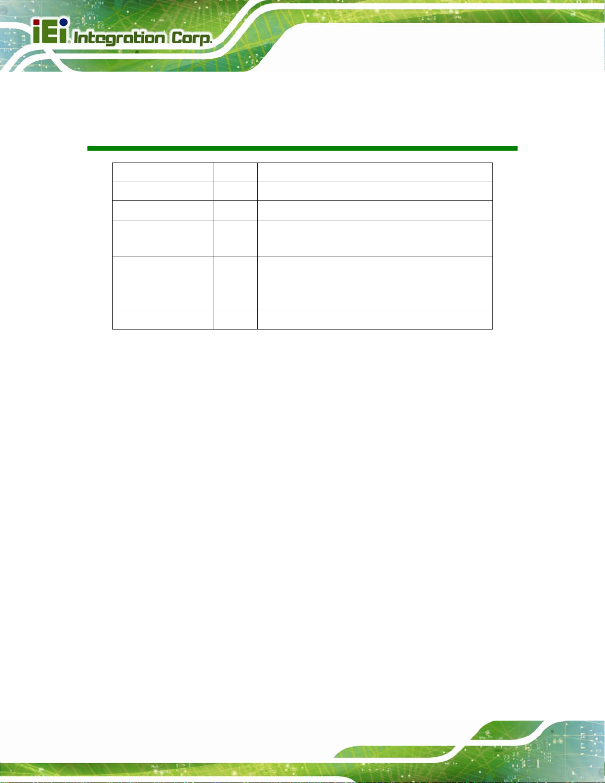
Figure 1-1: AVL-3000 Advanced Auto Data Server.....................................................................2
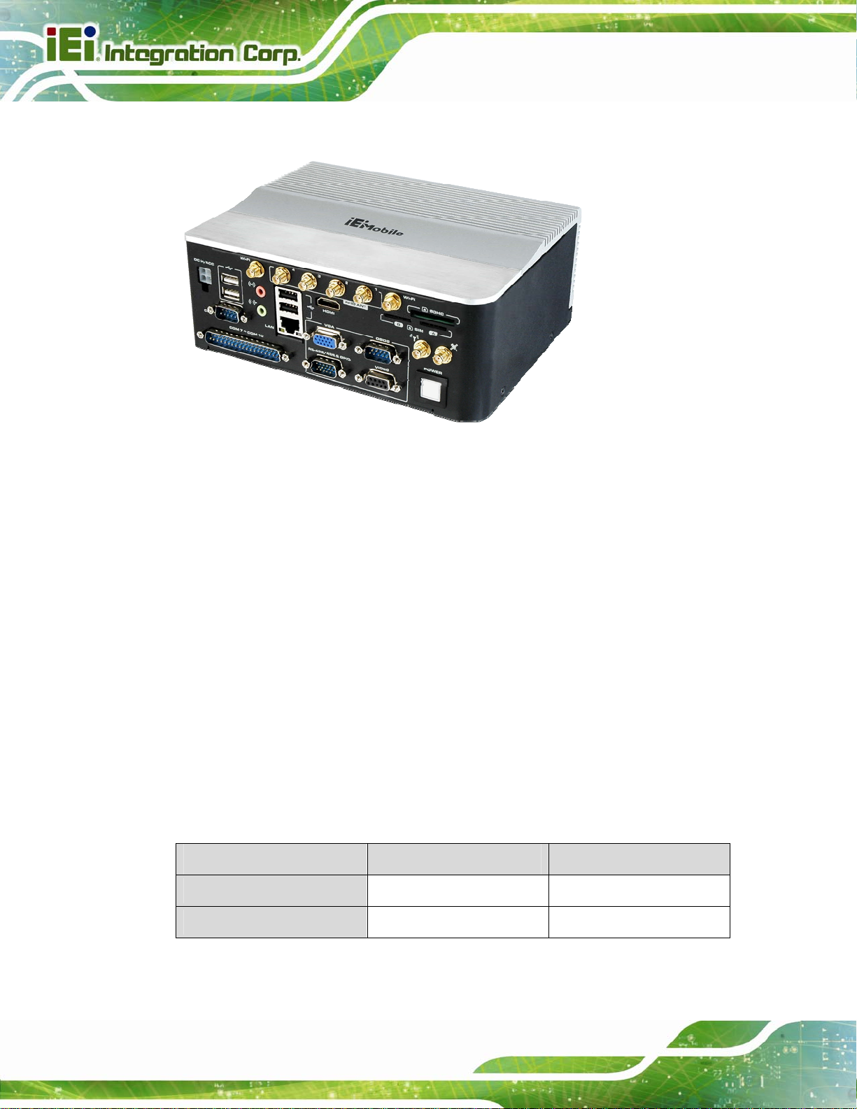
Figure 1-2: Front Panel ..................................................................................................................4
Figure 1-3: Bottom View ................................................................................................................5
Figure 1-4: Dimensions (unit: mm)...............................................................................................8
Figure 3-1: SDHC Card Installation.............................................................................................15
Figure 3-2: SIM Card Slot Locations...........................................................................................16
Figure 3-3: DIN Rail Mounting Bracket.......................................................................................17
Figure 3-4: Screw Locations........................................................................................................17
Figure 3-5: Mounting the DIN RAIL.............................................................................................18
Figure 3-6: Secure the Assembly to the DIN Rail......................................................................18
Figure 3-7: Audio Connectors.....................................................................................................19
Figure 3-8: HDMI Connection ......................................................................................................20
Figure 3-9: LAN Connection........................................................................................................21
Figure 3-10: OBD-II Cable and J1939/FMS Cable......................................................................21
Figure 3-11: OBD-II Connector Pinouts Location......................................................................22
Figure 3-12: OBD-II Connector Pinouts......................................................................................22
Figure 3-13: J1939/FMS Connector Pinouts..............................................................................23
Figure 3-14: Power Input Connector...........................................................................................23
Figure 3-15: Cigarette Lighter Cable...........................................................................................23
Figure 3-16: ACC Power Cable....................................................................................................24
Figure 3-17: Serial Device Connector.........................................................................................24
Figure 3-18: DB-9 RS-232 COM Port (COM1) Pinout Location.................................................25
Figure 3-19: DB-37 RS-232 COM Port (COM7 ~ COM10) Pinout Location..............................26
Figure 3-20: RS-422/485 & GPIO Connector Pinout Location..................................................27
Figure 3-21: USB Device Connection.........................................................................................27
Figure 3-22: Video Capture Cable...............................................................................................28
Figure 3-23: Video Connector Pinouts Location.......................................................................28
Figure 3-24: VGA Connector .......................................................................................................29
Figure 3-25: Power Connector and Power Button ....................................................................31
Figure 5-1: SIM CARD Switcher ..................................................................................................63
Page ix
Page 10

Figure 5-2: Phone .........................................................................................................................64
Figure 6-1: Main Board Layout Diagram (Front Side)...............................................................67
Figure 6-2: Main Board Layout Diagram (Solder Side).............................................................68
Figure B-1: IEI One Key Recovery Tool Menu...........................................................................90
Figure B-2: Launching the Recovery Tool.................................................................................95
Figure B-3: Recovery Tool Setup Menu .....................................................................................95
Figure B-4: Command Prompt ....................................................................................................96
Figure B-5: Partition Creation Commands.................................................................................97
Figure B-6: Launching the Recovery Tool.................................................................................99
Figure B-7: Manual Recovery Environment for Windows........................................................99
Figure B-8: Building the Recovery Partition........................................................................... 100
Figure B-9: Press Any Key to Continue.................................................................................. 100
Figure B-10: Press F3 to Boot into Recovery Mode............................................................... 101
Figure B-11: Recovery Tool Menu ........................................................................................... 101
A VL-3000 Advanced Auto Data Server
Figure B-12: About Symantec Ghost Window........................................................................ 102
Figure B-13: Symantec Ghost Path ......................................................................................... 102
Figure B-14: Select a Local Source Drive ............................................................................... 103
Figure B-15: Select a Source Partition from Basic Drive ...................................................... 103
Figure B-16: File Name to Copy Image to ............................................................................... 104
Figure B-17: Compress Image.................................................................................................. 104
Figure B-18: Image Creation Confirmation............................................................................. 105
Figure B-19: Image Creation Complete................................................................................... 105
Figure B-20: Image Creation Complete................................................................................... 105
Figure B-21: Press Any Key to Continue................................................................................ 106
Figure B-22: Auto Recovery Utility.......................................................................................... 107
Figure B-23: Disable Automatically Restart............................................................................ 107
Figure B-24: Launching the Recovery Tool............................................................................ 108
Figure B-25: Auto Recovery Environment for Windows ....................................................... 108
Figure B-26: Building the Auto Recovery Partition................................................................ 109
Figure B-27: Factory Default Image Confirmation ................................................................. 109
Figure B-28: Image Creation Complete................................................................................... 110
Figure B-29: Press any key to continue.................................................................................. 110
Figure B-30: Partitions for Linux.............................................................................................. 112
Figure B-31: System Configuration for Linux......................................................................... 113
Figure B-32: Access menu.lst in Linux (Text Mode).............................................................. 113
Page x
Page 11

A VL-3000 Advanced Auto Data Server
Figure B-33: Recovery Tool Menu ........................................................................................... 114
Figure B-34: Recovery Tool Main Menu.................................................................................. 115
Figure B-35: Restore Factory Default...................................................................................... 116
Figure B-36: Recovery Complete Window.............................................................................. 116
Figure B-37: Backup System.................................................................................................... 117
Figure B-38: System Backup Complete Window ................................................................... 117
Figure B-39: Restore Backup................................................................................................... 118
Figure B-40: Restore System Backup Complete Window..................................................... 118
Figure B-41: Symantec Ghost Window ................................................................................... 119
Figure B-42: Disable Automatically Restart............................................................................ 126
Page xi
Page 12

A VL-3000 Advanced Auto Data Server
List of Tables
Table 1-1: Model Variations...........................................................................................................2
Table 1-2: Technical Specifications..............................................................................................7
Table 2-1: Packing List.................................................................................................................11
Table 2-2: Optional Items.............................................................................................................12
Table 3-1: OBD-II Connector Pinouts .........................................................................................22
Table 3-2: DB-9 RS-232 COM Port (COM1) Pinouts ..................................................................25
Table 3-3: DB-37 RS-232 COM Port (COM7 ~ COM10) Pinouts................................................25
Table 3-4: RS-422/485 & GPIO Connector Pinouts....................................................................26
Table 3-5: Video Connector Pinouts...........................................................................................28
Table 3-6: Power Sate and Ignition System...............................................................................31
Table 4-1: BIOS Navigation Keys................................................................................................35
Table 6-1: Peripheral Interface Connectors...............................................................................69
Table 6-2: 5 V SATA Power Connector Pinouts ........................................................................69
Table 6-3: Battery Connector (BT1) Pinouts..............................................................................69
Table 6-4: Digital I/O and RS-422/485 Connector (DIO/RS422/485_1) Pinouts.......................70
Table 6-5: LPC Debug Card Connector (DBG_PORT1) Pinouts ..............................................70
Table 6-6: OBD-II Connector (OBDII1) Pinouts..........................................................................71
Table 6-7: PCI-104 Slot (PCI1) Pinouts.......................................................................................71
Table 6-8: PCIe Mini Card Slot (MINI_PCIE1) Pinouts...............................................................72
Table 6-9: PCIe Mini Card Slot (MINI_PCIE2) Pinouts...............................................................73
Table 6-10: PCIe Mini Card Slot (MINI_PCIE3) Pinouts.............................................................74
Table 6-11: Power Button and LED Connector (PWR_BTN1) Pinouts....................................75
Table 6-12: Programmer Connectors (JOBD1, MCU1) Pinouts...............................................75
Table 6-13: RS-232 Serial Port Connector, Four Ports (JCOM7) Pinouts...............................76
Table 6-14: RS-232 Serial Port Connector (COM1, COM6) Pinouts.........................................76
Table 6-15: SATA Drive Connector (SATA1) Pinouts ...............................................................77
Table 6-16: SPI Flash Connector (SPI1) Pinouts.......................................................................77
Table 6-17: USB 2.0 Connector (USB5) Pinouts........................................................................77
Table 6-18: Rear Panel Connectors............................................................................................78
Table 6-19: Ethernet Connector Pinouts....................................................................................78
Page xii
Page 13

A VL-3000 Advanced Auto Data Server
Table 6-20: Power Input Connector (PWIN1) Pinouts...............................................................78
Table 6-21: USB Connector (USB1) Pinouts..............................................................................79
Table 6-22: VGA Connector (VGA1) Pinouts .............................................................................79
Page xiii
Page 14

A VL-3000 Advanced Auto Data Server
BIOS Menus
BIOS Menu 1: Main.......................................................................................................................36
BIOS Menu 2: Advanced..............................................................................................................37
BIOS Menu 3: RTC Wake Settings..............................................................................................38
BIOS Menu 4: CPU Configuration...............................................................................................39
BIOS Menu 5: IDE Configuration.................................................................................................40
BIOS Menu 6: USB Configuration...............................................................................................41
BIOS Menu 7: Super IO Configuration........................................................................................42
BIOS Menu 8: Serial Port n Configuration Menu.......................................................................42
BIOS Menu 9: F81866 H/W Monitor.............................................................................................45
BIOS Menu 10: F81216 Second Super IO Configuration..........................................................46
BIOS Menu 11: F81216 Serial Port n Configuration Menu........................................................46
BIOS Menu 12: Serial Port Console Redirection.......................................................................50
BIOS Menu 13: IEI Feature...........................................................................................................52
BIOS Menu 14: Power Management ...........................................................................................53
BIOS Menu 15: Chipset................................................................................................................55
BIOS Menu 16: Host Bridge Configuration................................................................................55
BIOS Menu 17: Intel IGD Configuration......................................................................................56
BIOS Menu 18: South Bridge Chipset Configuration................................................................57
BIOS Menu 19: Boot.....................................................................................................................58
BIOS Menu 20: Security...............................................................................................................60
BIOS Menu 21:Exit........................................................................................................................61
BIOS Menu 22: IEI Feature........................................................................................................ 111
Page xiv
Page 15

A VL-3000 Advanced Auto Data Server
1 Introduction
Chapter
1
Page 1
Page 16
1.1 Overview
Figure 1-1: AVL-3000 Advanced Auto Data Server
A VL-3000 Advanced Auto Data Server
The AVL-3000 is an embedded system designed for in-car use.
At the heart of the system is the Intel® Atom™ N2600 processor, offering low power in a
powerful package. The chipset is rounded off with the Intel® NM10. The AVL-3000 is
preinstalled with 2.0 GB DDR3 memory and a 16 GB 2.5” SATA SSD.
The system supports HDMI/VGA display output and 802.11b/g/n wireless networking
capability. It also offers HSUPA/GPRS/GSM connection, Global Position System (GPS)
and On-Board Diagnostic System (OBD) technology. Other peripherals include four USB
ports, one GbE port, one RS-422/485 & GPIO connector, five RS-232 COM ports, video
capture port and audio line-in and line-out jacks.
1.2 Model Variations
The model variations of the AVL-3000 are listed below.
Model CPU Video Capture
AVL-3000-N26-HC-R20 Intel® N2600 1.6 GHz Hardware compression
Page 2
AVL-3000-N26-R20 Intel® N2600 1.6 GHz None
Table 1-1: Model Variations
Page 17

A VL-3000 Advanced Auto Data Server
1.3 Features
All of the AVL-3000 models feature the following:
Advanced auto data server with 1.6 GHz Intel® Atom™ N2600 CPU
2.0 GB DDR3 memory preinstalled
16 GB 2.5” SATA SSD preinstalled
Windows® Embedded Standard 7 OS preinstalled
Built-in Wi-Fi, Bluetooth, HSUPA and G PS with Dead Reckoning support
Supports vehicle power
NTSC/PAL/SECAM video capture by hardware compression
One SDHC card slot for data storage
10/100/1000 Mbps Ethernet
VGA and HDMI output ports
Two SIM card slots
Five RS-232 COM ports
One RS-422/485 & GPIO connector
Four USB ports
Audio mic-in and line-out
Optional UHF RFID reader module
Supports vehicle bus protocol (OBD-II/J1939/FMS)
DIN rail mount support
RoHS compliant
1.4 Front Panel
The following are found on the front panel.
1 x DC power input connector
1 x Gigabit Ethernet RJ-45 port
1 x GPS antenna connector (COM3, COM5)
1 x HDMI connector
1 x HSUPA antenna connector
1 x Line Out jack
1 x Microphone In jack
1 x OBD-II connector (COM4)
Page 3
Page 18
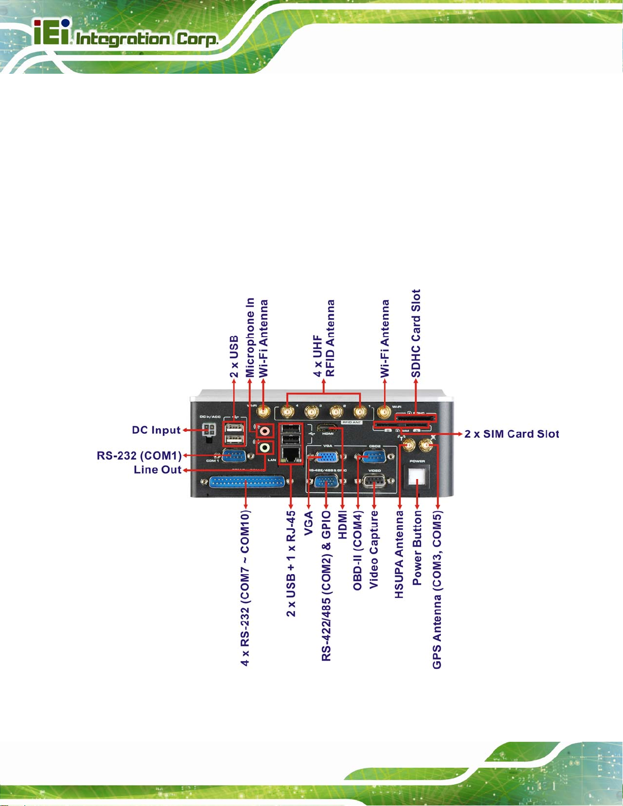
1 x Power button
1 x RS-232 COM port (COM1) (DB-9)
4 x RS-232 COM ports (COM7 ~ COM10) (DB-37)
1 x RS-422/485 (COM2) & GPIO connector
1 x SDHC card slot
2 x SIM card slots
1 x VGA connector
1 x Video capture connector
2 x Wi-Fi antenna connectors
4 x UHF RFID antenna connectors
4 x USB ports
A VL-3000 Advanced Auto Data Server
Page 4
Figure 1-2: Front Panel
Page 19
A VL-3000 Advanced Auto Data Server
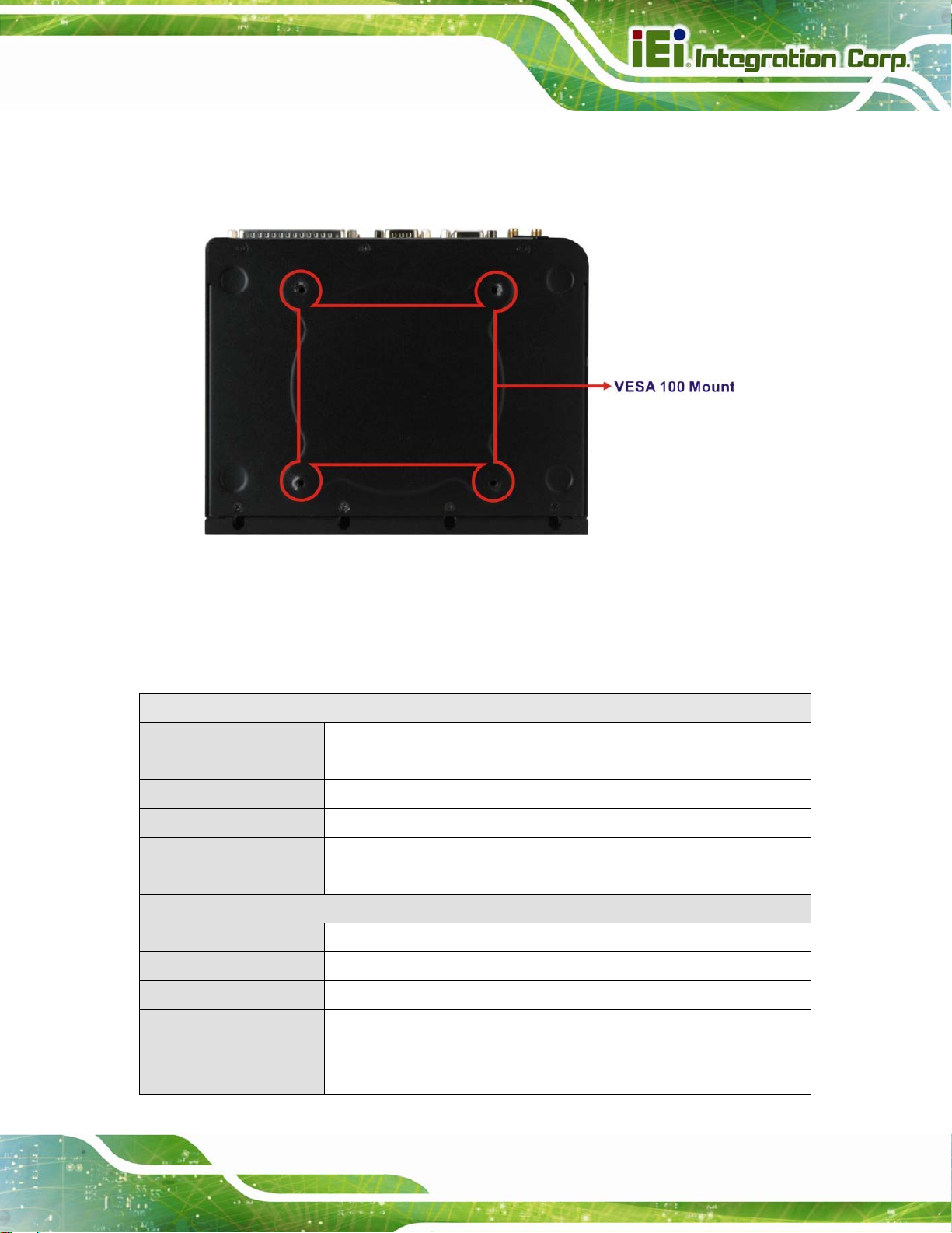
1.5 Bottom Panel
The bottom panel has VESA mounting screw holes for DIN rail mounting.
Figure 1-3: Bottom View
1.6 System Specifications
The AVL-3000 technical specifications are listed in Table 1-2.
System
CPU 1.6 GHz Intel® Atom™ N2600
Chipset Intel® NM10
Memory 2.0 GB 1333 MHz DDR3 preinstalled
OS Windows® Embedded Standard 7 preinstalled
1 x 16 GB 2.5” SATA SSD preinstalled
Storage
1 x SDHC card slot
Communication
LAN 1 x 10/100/1000 Mbps RJ-45
Wireless LAN 802.11b/g/n
Bluetooth Bluetooth v2.0+EDR (Class 1)
HSUPA/UMTS-800/850/900/1900/2100 MHz
3.75G
Quad-band EDGE/GPRS
GSM-850/900/1800/1900 MHz
Page 5
Page 20
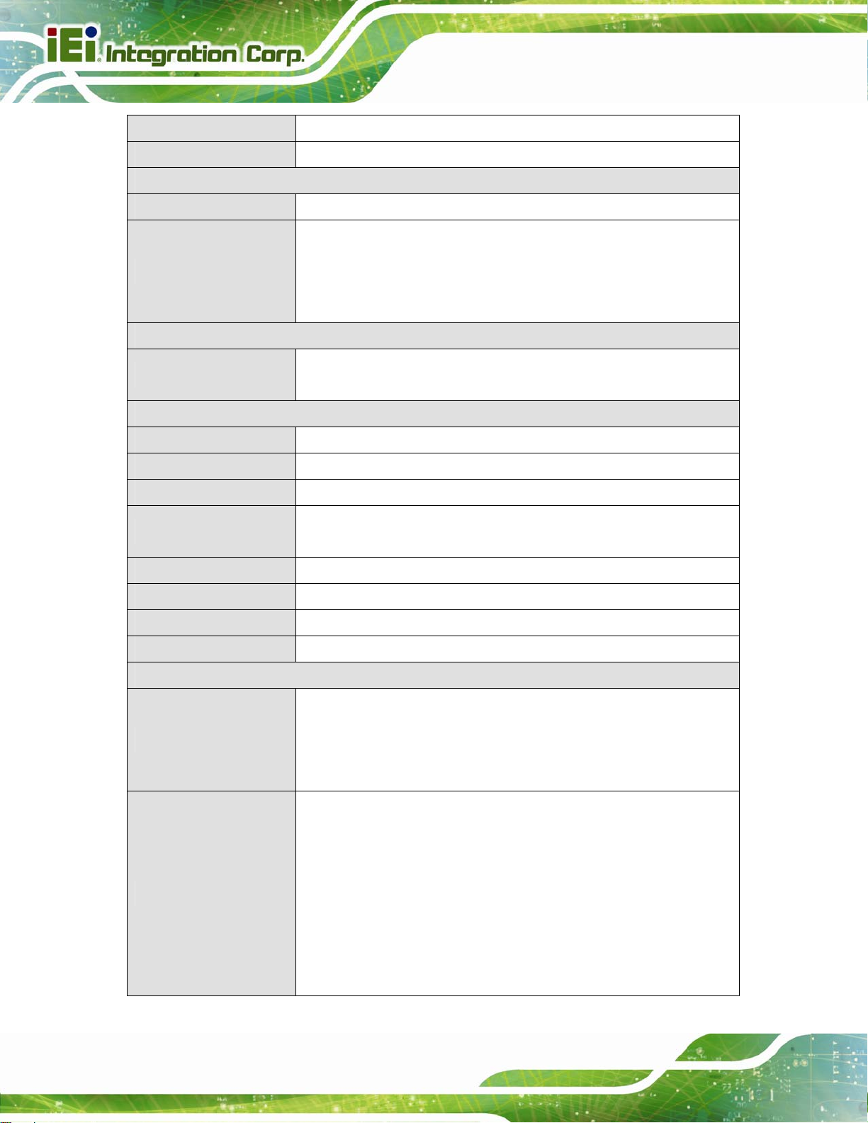
Dual-band EV-DO/CDMA
GPS GPS with Dead Reckoning support
Data Collection
RFID Optional IRFR-310 UHF RFID
Hardware compression: SC290N4 PCI104 (AVL-3000-N26-HC-R20)
A VL-3000 Advanced Auto Data Server
Video Capture
Power
Power Input
Environmental and Physical Specifications
Mounting DIN rail mount (VESA 100 mm x 100 mm)
Dimensions (W x D x H) 200 mm x 150 mm x 76 mm
Weight 2015 g
Operating Temperature
Storage Temperature -30ºC ~ 80ºC
Humidity 5% ~ 95% (non-condensing)
Drop Survival IEC60068-2-31
Safety CE, FCC, e-MARK
Video input: 4-channel composite video (NTSC/PAL/SECAM)
Frame rate: Total 120fps@QVGA (320x240) for four channels (NTSC), total
100fps@QVGA (320x240) for four channels (PAL/SECAM)
9 V ~ 36 V DC input
Cigarette lighter power or ACC power
-20ºC ~ 70ºC
-20ºC ~ 50ºC (with UHF RFID)
Connectors and Buttons
Antenna Connectors
I/O Ports and Buttons
Page 6
1 x GPS antenna connector
1 x HSUPA antenna connector
2 x Wi-Fi antenna connectors
4 x UHF RFID antenna connectors (optional)
1 x 12 V DC power input connector
1 x Gigabit Ethernet RJ-45 port
1 x HDMI connector
1 x Line Out jack
1 x Microphone In jack
1 x OBD-II connector (COM4)
1 x Power button
1 x RS-232 COM port (COM1) (DB-9)
Page 21

A VL-3000 Advanced Auto Data Server
4 x RS-232 COM port (COM7 ~ COM10) (DB-37)
1 x RS-422/485 (COM2) & GPIO connector
1 x SDHC card slot
2 x SIM card slots
1 x Video capture connector
1 x VGA connector
4 x USB ports
Table 1-2: Technical Specifications
Page 7
Page 22
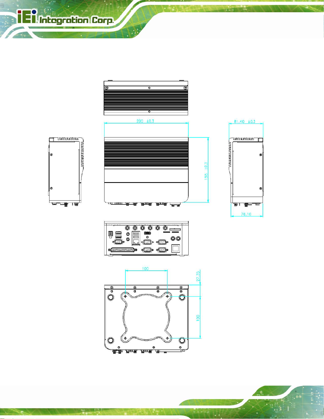
1.7 Dimensions
The dimensions are shown below.
A VL-3000 Advanced Auto Data Server
Page 8
Figure 1-4: Dimensions (unit: mm)
Page 23

A VL-3000 Advanced Auto Data Server
Chapter
2
2 Unpacking
Page 9
Page 24
To unpack the AVL-3000, follow the steps below:
Step 1: Use box cutters, a knife or a sharp pair of scissors that seals the top side of the
external (second) box.
Step 2: Open the external (second) box.
Step 3: Use box cutters, a knife or a sharp pair of scissors that seals the top side of the
internal (first) box.
Step 4: Lift the monitor out of the boxes.
Step 5: Remove both polystyrene ends, one from each side.
Step 6: Pull the plastic cover off the AVL-3000.
Step 7: Make sure all the components listed in the pa cking list are present. Step 0:
A VL-3000 Advanced Auto Data Server
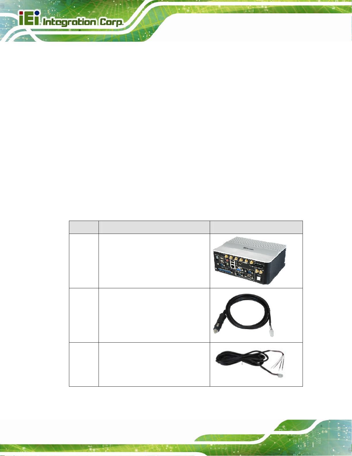
The AVL-3000 is shipped with the following components:
Quantity Item Image
1 AVL-3000
1 Cigarette lighter power cable
(P/N: 32002-001800-100-RS)
1 ACC power cable
(P/N: 32002-001900-100-RS)
Page 10
Page 25
A VL-3000 Advanced Auto Data Server
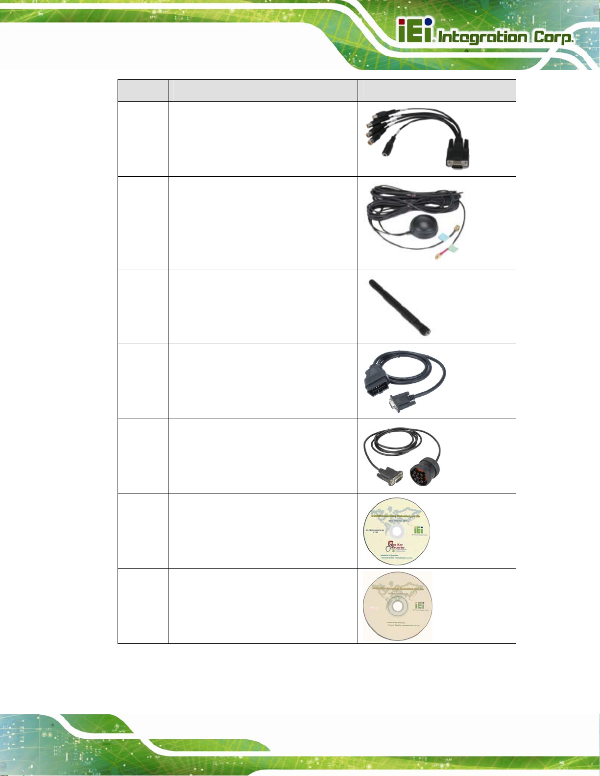
Quantity Item Image
1 Capture cable
(P/N: 32007-001400-100-RS)
1 GPS/GSM antenna
(P/N: 32506-000100-100-RS)
2 Wi-Fi antenna
(P/N: 32505-000400-100-RS)
1 OBD-II cable
(P/N: 32025-000300-100-RS)
1 J1939/FMS cable
(P/N: 32025-000400-100-RS)
1 One Key Recovery CD
1 User manual CD and driver CD
Table 2-1: Packing List
Page 11
Page 26

The following table lists the optional items that can be purchased separately.
Item Image
UHF RFID antenna with cable
Table 2-2: Optional Items
If any of these items are missing or damaged, contact the distributor or sales
representative immediately.
A VL-3000 Advanced Auto Data Server
Page 12
Page 27

A VL-3000 Advanced Auto Data Server
Chapter
3
3 Installation
Page 13
Page 28

3.1 Anti-static Precautions
WARNING:
Failure to take ESD precautions during the maintenance of the
AVL-3000 may result in permanent damage to the AVL-3000 and
severe injury to the user.
Electrostatic discharge (ESD) can cause serious damage to electronic components,
including the AVL-3000. Dry climates are especially susceptible to ESD. It is therefore
critical that whenever the AVL-3000 is accessed internally, or any other electrical
component is handled, the following anti-static precautions are strictly adhered to.
Wear an anti-static wristband: - Wearing a simple anti-static wristband can
A VL-3000 Advanced Auto Data Server
help to prevent ESD from damaging the board.
Self-grounding: - Before handling the board touch any grounded conducting
material. During the time the board is handled, frequently touch any
conducting materials that are connected to the ground.
Use an anti-static pad: - When configuring the AVL-3000, place it on an
antic-static pad. This reduces the possibility of ESD damaging the AVL-3000.
Only handle the edges of the PCB: - When handling the PCB, hold the PCB
by the edges.
3.2 Installation Precautions
When installing the AVL-3000, please follow the precautions listed below:
Power turned off: When installing the AVL-3000, make sure the power is off.
Failing to turn off the power may cause severe injury to the body and/or
damage to the system.
Certified Engineers: Only certified engineers should install and modify
onboard functionalities.
Page 14
Anti-static Discharge : If a user open the bottom panel of the AVL-3000, to
configure the jumpers or plug in added peripheral devices, ground themselves
first and wear and anti-static wristband.
Page 29
A VL-3000 Advanced Auto Data Server
3.3 Installation and Configuration Steps
The following installation steps must be followed.
Step 1: Unpack the system
Step 2: Install a SIM card or SDHC card (optional)
Step 3: Connect peripheral devices
Step 4: Mount the system
Step 5: Power up the system Step 0:
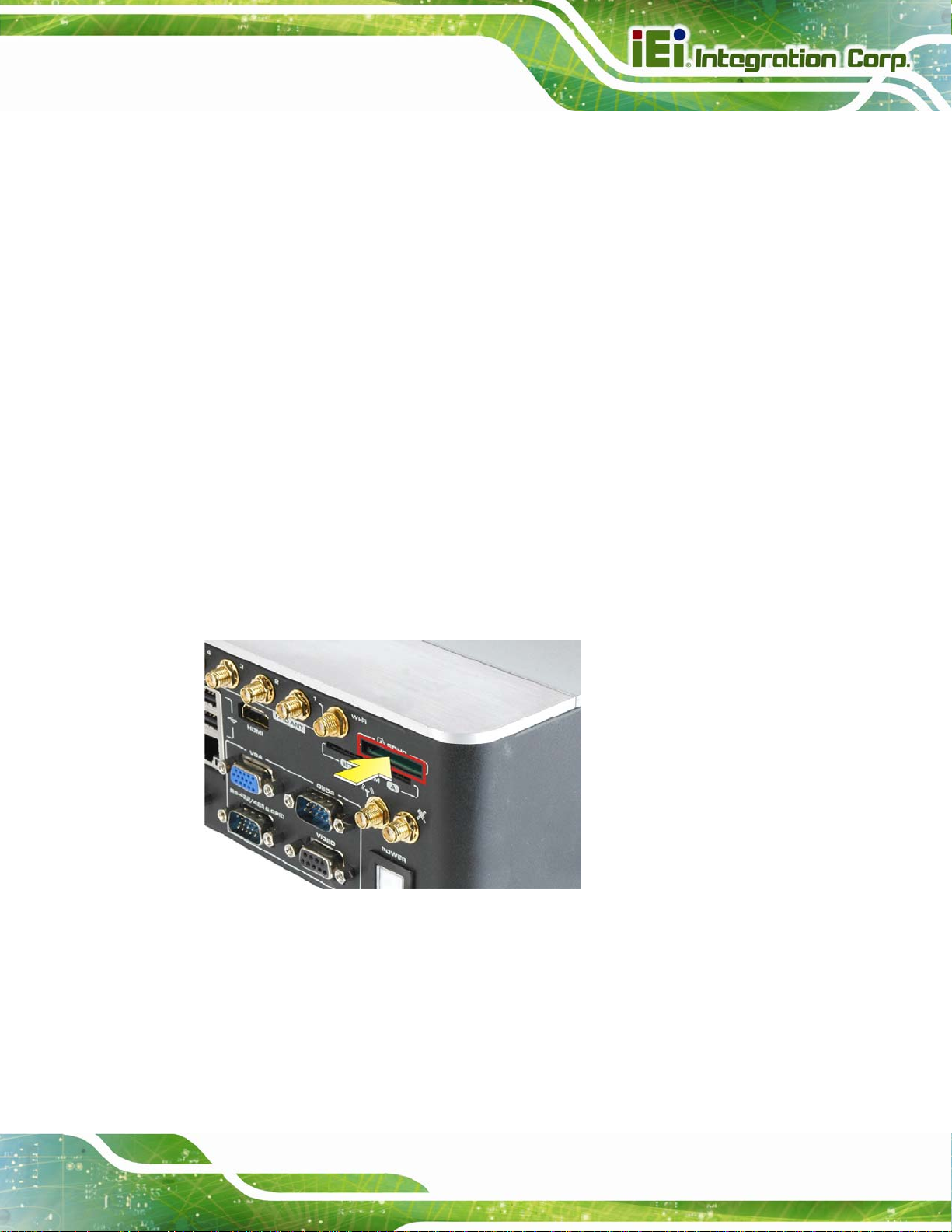
3.4 SDHC Card Installation
To install an SDHC card, follow the instructions below.
Step 1: Locate the SDHC card slot.
Step 2: Insert the SDHC card into the slot.
Figure 3-1: SDHC Card Installation
Page 15
Page 30
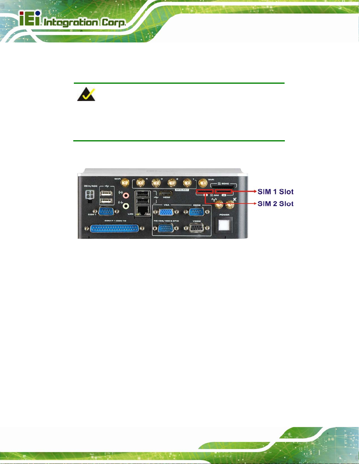
3.5 SIM Card Installation
The AVL-3000 has two SIM card slots. To install a SIM card, follow the instructions below.
NOTE:
The AVL-3000 provides an application for setting which SIM card to
A VL-3000 Advanced Auto Data Server
use. Refer to Section
Step 1: Locate the SIM card slot. See Figure 3-2.
Figure 3-2: SIM Card Slot Locations
Step 2: Insert a SIM card into the slot.
3.6 Mounting the System
5.1.1 for details.
Page 16
To mount the system onto a DIN rail, please follow the steps below.
Step 1: Attach the DIN rail mounting bracket to the bottom panel of the AVL-3000.
Secure the bracket to the AVL-3000 with the supplied retention screws (
3-3).
75Figure
Page 31

A VL-3000 Advanced Auto Data Server
Figure 3-3: DIN Rail Mounting Bracket
Step 2: Make sure the inserted screw in the center of the bracket is at the lowest
position of the elongated hole (
75Figure 3-4).
Figure 3-4: Screw Locations
Step 3: Place the DIN rail flush against the back of the mounting bracket making sure
the edges of the rail are between the upper and lower clamp s (
75Figure 3-5).
Page 17
Page 32

A VL-3000 Advanced Auto Data Server
Figure 3-5: Mounting the DIN RAIL
Step 4: Secure the DIN rail to the mounting bracket by turning the top screw clockwise.
This draws the lower clamp up and secures the AVL-3000 to the DIN rail (
3-6).
Figure 3-6: Secure the Assembly to the DIN Rail
75Figure
Page 18
Page 33

A VL-3000 Advanced Auto Data Server
3.7 I/O Interface Connectors
This section provides an overview of the I/O interface connectors of the AVL-3000.
NOTE:
The following lists the device ports for the corresponding connectors.
RS-422/485: COM 2
OBD-II/CAN: COM 4
GPS: COM 3, COM 5 for data
GSM/GPRS: USB port
3.7.1 Audio Connectors
The audio jacks connect to external audio devices.
Microphone In port (Pink): Connects a microphone.
Line Out port (Green): Connects to a headphone or a speaker.
Figure 3-7: Audio Connectors
3.7.2 HDMI Display Device Connection
The HDMI connector transmits a digital signal to compatible HDMI display devices such
as a TV or computer screen. To connect the HDMI cable to the AVL-3000, follow the steps
below.
Step 1: Locate the HDMI connector. The location is shown in
Figure 1-2.
Page 19
Page 34

Step 2: Align the connector. Align the HDMI connector with the HDMI port. Make sure
the orientation of the connector is correct.
Figure 3-8: HDMI Connection
A VL-3000 Advanced Auto Data Server
Step 3: Insert the HDMI connector. Gently insert the HDMI connector. The connector
should engage with a gentle push. If the connector does not insert easily, check
again that the connector is aligned correctly, and that the connector is being
inserted with the right way up.
3.7.3 LAN Connection
There is one external RJ-45 LAN connector. The RJ-45 connector enables connection to
an external network. To connect a LAN cable with an RJ-45 connector, please follow the
instructions below.
Step 1: Locate the RJ-45 connector on the front panel of the AVL-3000.
Step 2: Align the connectors. Align the RJ-45 connector on the LAN cable with the
RJ-45 connector on the front panel of the AVL-3000.
Page 20
Page 35

A VL-3000 Advanced Auto Data Server
Figure 3-9: LAN Connection
Step 3: Insert the LAN cable RJ-45 connector. Once aligned, gently insert the LAN
cable RJ-45 connector into the onboard RJ-45 connector. Step 0:
3.7.4 OBD-II Connector (COM4)
The AVL-3000 has one DB-9 male connector for OBD-II connection. Use the OBD-II cable
or J1939/FMS cable (
vehicle.
OBD-II Cable
Figure 3-10: OBD-II Cable and J1939/FMS Cable
Figure 3-10) in the package to connect the AVL-3000 with the
J1939/FMS Cable
The pinouts for OBD-II connector are listed in the table below.
Page 21
Page 36

A VL-3000 Advanced Auto Data Server
Figure 3-11: OBD-II Connector Pinouts Location
Pin Description
1 NC
2 NC
3 OBD-CAN_H
4 ISO-9141-2-K
5 OBD-CAN_L
6 J18507 J1850+
8 ISO-9141-2-L
9 NC
Table 3-1: OBD-II Connector Pinouts
The pinout locations of OBD-II cable connector and J1939/FMS cable connector are
shown below.
Page 22
Figure 3-12: OBD-II Connector Pinouts
Page 37

A VL-3000 Advanced Auto Data Server
Figure 3-13: J1939/FMS Connector Pinouts
3.7.5 Power Input Connection
The AVL-3000 has one 12 V DC input connector on the front panel.
Figure 3-14: Power Input Connector
The AVL-3000 can use either ACC power or DC power from the ve hicle. To use DC power,
connect the AVL-3000 to the vehicle cigarette lighter connector through the cigarette
lighter cable. See
Figure 3-15: Cigarette Lighter Cable
To use ACC power, connect the AVL-3000 to the vehicle through the ACC power cable.
See
Figure 3-16.
Figure 3-15.
Page 23
Page 38

Figure 3-16: ACC Power Cable
3.7.6 DB-9 RS-232 COM Port (COM1)
The AVL-3000 has one DB-9 RS-232 COM port on the front panel for serial devices to be
connected. Follow the steps below to connect a serial device to the AVL-3000.
Step 1: Locate the DB-9 connector. The location of the DB-9 connector is shown in
Figure 1-2.
A VL-3000 Advanced Auto Data Server
Step 2: Insert the serial connector. Insert the DB-9 connector of a serial device into
the DB-9 connector on the front panel. See
Figure 3-17: Serial Device Connector
Figure 3-17.
Page 24
Step 3: Secure the connector. Secure the serial device connector to the external
interface by tightening the two retention screws on either side of the connector.
Page 39

A VL-3000 Advanced Auto Data Server
Pin Description Pin Description
1 DCD 6 DSR
2 RX 7 RTS
3 TX 8 CTS
4 DTR 9 RI
5 GND
Table 3-2: DB-9 RS-232 COM Port (COM1) Pinouts
Figure 3-18: DB-9 RS-232 COM Port (COM1) Pinout Location
3.7.7 DB-37 RS-232 COM Port (COM7 ~ COM10)
The AVL-3000 has one DB-37 RS-232 COM port on the front panel for serial d evices to be
connected. The pinouts for the DB-37 connector are listed in the table below.
Pin Definition COM7 COM8 COM9 COM10
DCD 1 6 11 16
RX 2 7 12 17
TX 3 8 13 18
DTR 4 9 14 19
GND 5 10 15 36
DSR 20 24 28 32
RTS 21 25 29 33
CTS 22 26 30 34
RI 23 27 31 35
NC 37
Table 3-3: DB-37 RS-232 COM Port (COM7 ~ COM10) Pinouts
Page 25
Page 40

A VL-3000 Advanced Auto Data Server
Figure 3-19: DB-37 RS-232 COM Port (COM7 ~ COM10) Pinout Location
3.7.8 RS-422/485 (COM2) & GPIO Connector
The AVL-3000 has one male DB-15 connector on the front panel. The pinouts for the male
DB-15 connector are listed in the table below.
Pin GPIO RS-422 RS-485
1 D_IN0
2 D_IN1
3 D_IN2
4 D_IN3
5 +5V
6 D_OUT0
7 D_OUT1
8 D_OUT2
9 D_OUT3
10 GND GND GND
11 TXD- Data12 TXD+ Data+
13 RXD-
14 RXD+
15 NC NC NC
Table 3-4: RS-422/485 & GPIO Connector Pinouts
Page 26
Page 41

A VL-3000 Advanced Auto Data Server
Figure 3-20: RS-422/485 & GPIO Connector Pinout Location
3.7.9 USB Device Connection
There are four external USB connectors. To connect a USB device, please follow the
instructions below.
Step 1: Located the USB connectors. The locations of the USB connectors are shown
Figure 1-2.
in
Step 2: Align the connectors. Align the USB device connector with one of the
connectors on the front panel.
Figure 3-21: USB Device Connection
Step 3: Insert the device connector. Once aligned, gently insert the USB device
connector into the onboard connector. Step 0:
Page 27
Page 42

3.7.10 Video Capture Connection
The AVL-3000 has one DB-9 female connector for video capture connection. Use the
A VL-3000 Advanced Auto Data Server
video cable (
Figure 3-22) in the package to connect the AVL-3000 with the device.
Figure 3-22: Video Capture Cable
The pinouts for video connector are listed in the table below.
Figure 3-23: Video Connector Pinouts Location
Pin Description
1 CN1_A
2 CN1_B
3 CN1_C
4 CN1_D
5 SIN1_A
6 GND
7 GND
8 GND
9 GND
Table 3-5: Video Connector Pinouts
Page 28
Page 43

A VL-3000 Advanced Auto Data Server
3.7.11 VGA Monitor Connection
The AVL-3000 has a female DB-15 connector on the front panel. The DB-15 connector is
connected to a CRT or VGA monitor. To connect a monitor to the AVL-3000, please follow
the instructions below.
Step 1: Locate the female DB-15 connector. The location of the female DB-15
connector is shown in
Step 2: Align the VGA connector. Align the male DB-15 connector on the VGA screen
cable with the female DB-15 connector on the external peripheral interface.
Step 3: Insert the VGA connector. Once the conne ctors are prop erly aligned with,
insert the male connector from the VGA screen into the female connector on the
AVL-3000. See
Figure 1-2.
Figure 3-24.
Figure 3-24: VGA Connector
Step 4: Secure the connector. Secure the DB-15 VGA connector from the VGA
monitor to the external interface by tightening the two retention screws on either
side of the connector. Step 0:
Page 29
Page 44

3.8 Power-On Procedure
3.8.1 Installation Checklist
WARNING:
Make sure a power supply with the correct input voltage is being fed into
the system. Incorrect voltages applied to the system may cause damage to
the internal electronic components and may also cause injury to the user.
To power on the AVL-3000, please make sure of the following:
The SIM card is installed
A VL-3000 Advanced Auto Data Server
The bottom cover is installed
All peripheral devices (antenna, serial communications devices etc.) are
connected
The system is securely mounted
The power cables are plugged in
3.8.2 Power-on Procedure
To power-on the AVL-3000 please follow the steps below:
Step 1: Connect either the cigarette lighter power cable or ACC power cable from the
AVL-3000 to the vehicle.
Step 2: Push the power button for five seconds to turn on the system. See
Figure 3-25.
Page 30
Page 45

A VL-3000 Advanced Auto Data Server
Figure 3-25: Power Connector and Power Button
3.8.3 Power State
The following table shows the relation of the power state and vehicle ignition system. The
auto start-up and shut down time delay can be set by the AVL-3000 software application.
LOCK
ACC Signal Off On On Off
Car Cigarette Lighter Off On On Off
5 V Standby Power Off On after 1 second
Auto Start-up -- After 10~60 seconds (selectable) --
After 10~180
Auto Shut-down
secs (selectable)
ACC
-- -- --
ON
On On
START
Table 3-6: Power Sate and Ignition System
Page 31
Page 46

3.9 System Maintenance
If the components of the AVL-3000 fail, they must be replaced. Please contact the system
reseller or vendor to purchase the replacement parts.
NOTE:
A user cannot replace a motherboard. If the motherboard fails it must
be shipped back to IEI to be replaced. Please contact the system
vendor, reseller or an IEI sales person directly.
A VL-3000 Advanced Auto Data Server
Page 32
Page 47

A VL-3000 Advanced Auto Data Server
Chapter
4
4 BIOS
Page 33
Page 48

4.1 Introduction
The BIOS is programmed onto the BIOS chip. The BIOS setup program allows changes to
certain system settings. This chapter outlines the options that can be changed.
4.1.1 Starting Setup
The UEFI BIOS is activated when the computer is turned on. The setup program can be
activated in one of two ways.
1. Press the DEL or F2 key as soon as the system is turned on or
2. Press the DEL or F2 key when the “Press DEL or F2 to enter SETUP”
message appears on the screen.
A VL-3000 Advanced Auto Data Server
If the message disappears before the DEL or F2
try again.
key is pressed, restart the co mpu ter and
4.1.2 Using Setup
Use the arrow keys to highlight items, press ENTER to select, use the PageUp and
PageDown keys to change entries, press F1 for help and press E
keys are shown in.
Key Function
Up arrow Move to previous item
Down arrow Move to next item
Left arrow Move to the item on the left hand side
Right arrow Move to the item on the right hand side
+ Increase the numeric value or make changes
- Decrease the numeric value or make changes
SC to quit. Navigation
Page 34
Page Up key Move to the previous page
Page Dn key Move to the next page
Page 49

A VL-3000 Advanced Auto Data Server
Key Function
Esc key Main Menu – Quit and not save changes into CMOS
Status Page Setup Menu and Option Page Setup Menu -Exit current page and return to Main Menu
F1 General help, only for St atus Page Setup Menu and Option
Page Setup Menu
F2 Load previous values
F3 Load optimized defaults
F4 Save changes and Exit BIOS
Table 4-1: BIOS Navigation Keys
4.1.3 Getting Help
When F1 is pressed a small help window describing the appropriate keys to use and the
possible selections for the highlighted item appears. To exit the Help Window press E
the F1 key again.
4.1.4 BIOS Menu Bar
The menu bar on top of the BIOS screen has the following main items:
Main – Changes the basic system configuration.
Advanced – Changes the advanced system settings.
Chipset – Changes the chipset settings.
Boot – Changes the system boot configuration.
Security – Sets User and Supervisor Passwords.
Save & Exit – Selects exit options and loads default settings
The following sections completely describe the configuration options found in the menu
items at the top of the BIOS screen and listed above.
SC or
Page 35
Page 50

A VL-3000 Advanced Auto Data Server
4.2 Main
The Main BIOS menu (BIOS Menu 1) appears when the BIOS Setup program is entered.
The Main menu gives an overview of the basic system information.
Aptio Setup Utility – Copyright (C) 2011 American Megatrends, Inc.
Main Advanced Chipset Boot Security Save & Exit
BIOS Information
BIOS Vendor American Megatrends
Core Version 4.6.5.1 0.13
Compliancy UEFI 2.3; PI 1.2
Project Version Z181AT21.ROM
Build Date and Time 12/28/2012 11:53:40
System Date [Tue 04/09/2013]
System Time [15:10:27]
Access Level Administrator
Version 2.14.1219. Copyright (C) 2011 American Megatrends, Inc.
Set the Date. Use Tab to
switch between Data
elements.
----------------------
↑ ↓: Select Item
Enter: Select
+/-: Change Opt.
F1: General Help
F2: Previous Values
F3: Optimized Defaults
F4: Save & Exit
ESC: Exit
: Select Screen
BIOS Menu 1: Main
BIOS Information
The BIOS Information lists a brief summary of the BIOS. The fields in BIOS Information
cannot be changed. The items shown in the system overview include:
BIOS Vendor: Installed BIOS vendor
Core Version: Current BIOS version
Project Version: the bo ard version
Build Date and Time: Date and time the current BIOS version was made
The System Overview field also has two user configurable fields:
System Date [xx/xx/xx]
Use the System Date option to set the system date. Manually enter the day, month and
year.
Page 36
Page 51

A VL-3000 Advanced Auto Data Server
System Time [xx:xx:xx]
Use the System Time option to set the system time. Manually enter the hours, minutes
and seconds.
4.3 Advanced
Use the Advanced menu (BIOS Menu 2) to configure the CPU and peripheral devices
through the following sub-menus:
WARNING:
Setting the wrong values in the sections below may cause the system
to malfunction. Make sure that the settings made are compatible with
the hardware.
> RTC Wake Settings
> CPU Configuration
> IDE Configuration
> USB Configuration
> F81866 Super IO Configuration
> F81866 H/W Monitor
> F81216 Second Super IO Configuration
> Serial Port Console Redirection
> iEi Feature
> Power Management
Aptio Setup Utility – Copyright (C) 2011 American Megatrends, Inc.
Main Advanced Chipset Boot Security Save & Exit
Enable system to make
from Soft-off, S3, S4,
S5, using RTC alarm
----------------------
↑ ↓: Select Item
Enter: Select
+/-: Change Opt.
F1: General Help
F2: Previous Values
F3: Optimized Defaults
F4: Save & Exit
ESC: Exit
Version 2.14.1219. Copyright (C) 2011 American Megatrends, Inc.
BIOS Menu 2: Advanced
4.3.1 RTC Wake Settings
: Select Screen
The RTC Wake Settings menu (BIOS Menu 3) enables the system to wake at the
specified time.
Page 37
Page 52

E
w
Aptio Setup Utility – Copyright (C) 2011 American Megatrends, Inc.
Advanced
Wake system with Fixed Time [Disabled]
Version 2.14.1219. Copyright (C) 2011 American Megatrends, Inc.
A VL-3000 Advanced Auto Data Server
nable or disable System
ake on alarm event. When
enabled, System will
wake on the
date::hr::min::sec
specified
----------------------
: Select Screen
↑ ↓: Select Item
Enter: Select
+/-: Change Opt.
F1: General Help
F2: Previous Values
F3: Optimized Defaults
F4: Save & Exit
ESC: Exit
BIOS Menu 3: RTC Wake Settings
Wake system with Fixed Time [Disab led]
Use the Wake system with Fixed Time option to enable or disable the system wake on
alarm event.
Disabled D
Enabled
EFAULT
The real time clock (RTC) cannot generate a wake
event
If selected, the Wake up every day option appears
allowing you to enable to disable the system to wake
every day at the specified time. Besides, the
following options appear with values that can be
selected:
Wake up date
Wake up hour
Wake up minute
Wake up second
After setting the alarm, the computer turns itself on
from a suspend state when the alarm goes off.
Page 38
Page 53

a
T
A VL-3000 Advanced Auto Data Server
4.3.2 CPU Configuration
Use the CPU Configuration menu (BIOS Menu 4) to view detailed CPU specifications
and configure the CPU.
Aptio Setup Utility – Copyright (C) 2011 American Megatrends, Inc.
Advanced
CPU Configuration
Processor Type Intel(R) Atom(TM)
CPU N2600 @ 1.60GHz
EMT64 Supported
Processor Speed 1600 MHz
System Bus Speed 400 MHz
Ratio Status 16
Actual Ratio 16
System Bus Speed 400 MHz
Processor Stepping 30661
Microcode Revision 269
L1 Cache RAM 2x56 k
L2 Cache RAM 2x512 k
Processor Core Dual
Hyper-Threading Supported
Hyper-Threading [Enabled]
Version 2.14.1219. Copyright (C) 2011 American Megatrends, Inc.
Enabled for Windows XP
nd Linux (OS optimized
for Hyper-Threading
echnology) and Disabled
for other OS (OS not
optimized for
Hyper-Threading
Technology).
----------------------
: Select Screen
↑ ↓: Select Item
Enter: Select
+/-: Change Opt.
F1: General Help
F2: Previous Values
F3: Optimized Defaults
F4: Save & Exit
ESC: Exit
BIOS Menu 4: CPU Configuration
The CPU Configuration menu (
Processor Type: Lists the brand name of the CPU being used.
EMT64: Indicates if EMT64 is supported by the CPU.
Processor Speed: Lists the CPU proce ssing speed.
System Bus Speed: Lists the system bus speed.
Ratio Status: Lists the ratio status.
Actual Ratio: Lists the ratio of the frequency to the clock speed.
Processor Stepping: Lists the CPU ID.
Microcode Revision: Lists the microcode revision.
L1 Cache RAM: Lists the CPU L1 cache size.
L2 Cache RAM: Lists the CPU L2 cache size.
Processor Core: Lists the number of the processor core.
Hyper-Threading: Indicates if Intel HT Technology is supported by the CPU.
BIOS Menu 4) lists the following CPU details:
Page 39
Page 54

Hyper-Threading [Enabled]
Use the Hyper-Threading BIOS option to enable or disable the Intel Hyper-Threading
Technology.
A VL-3000 Advanced Auto Data Server
Disabled
Enabled DEFAULT
Disables the Intel Hyper-Threading Technology.
Enables the Intel Hyper-Threading Technology.
4.3.3 IDE Configuration
Use the IDE Configuration menu (BIOS Menu 5) to change and/or set the configuration
of the SATA devices installed in the system.
Aptio Setup Utility – Copyright (C) 2011 American Megatrends, Inc.
Advanced
SATA1 EverGreen 2.5 (15.4G)
Configure SATA as [IDE]
Version 2.14.1219. Copyright (C) 2011 American Megatrends, Inc.
Select a configuration
for SATA Controller.
---------------------
: Select Screen
↑ ↓: Select Item
Enter: Select
+/-: Change Opt.
F1: General Help
F2: Previous Values
F3: Optimized Defaults
F4: Save & Exit
ESC: Exit
BIOS Menu 5: IDE Configuration
Configure SATA as [IDE]
Use the Configure SATA as option to configure SATA devices as normal IDE or AHCI
devices.
IDE DEFAULT
AHCI
Page 40
Configures SATA devices as normal IDE device.
Configures SATA devices as AHCI device.
Page 55

d
A VL-3000 Advanced Auto Data Server
4.3.4 USB Configuration
Use the USB Configuration menu (BIOS Menu 6) to read USB configuration information
and configure the USB settings.
Aptio Setup Utility – Copyright (C) 2011 American Megatrends, Inc.
Advanced
USB Configuration
USB Devices:
None
Legacy USB Support [Enabled]
Version 2.14.1219. Copyright (C) 2011 American Megatrends, Inc.
Enables Legacy USB
support. AUTO option
isables legacy support
if no USB devices are
connected. DISABLE
option will keep USB
devices available only
for EFI applications.
---------------------
: Select Screen
↑ ↓: Select Item
Enter: Select
+/-: Change Opt.
F1: General Help
F2: Previous Values
F3: Optimized Defaults
F4: Save & Exit
ESC: Exit
BIOS Menu 6: USB Configuration
Legacy USB Support [Enabled]
Use the Legacy USB Support BIOS option to enable USB mouse and USB keyboard
support.
Normally if this option is not enabled, any attached USB mouse or USB keyboard does not
become available until a USB compatible operating system is fully booted with all USB
drivers loaded. When this option is enabled, any attached USB mouse or USB keyboard
can control the system even when there is no USB driver loaded onto the system.
Disabled
Enabled DEFAULT
Auto
Legacy USB support disabled
Legacy USB support enabled
Legacy USB support disabled if no USB devices are
connected
Page 41
Page 56

S
E
A VL-3000 Advanced Auto Data Server
4.3.5 F81866 Super IO Configuration
Use the F818666 Super IO Configuration menu (BIOS Menu 7) to set or change the
configurations for the serial ports.
Aptio Setup Utility – Copyright (C) 2011 American Megatrends, Inc.
Advanced
F81866 Super IO Configuration
F81866 Super IO Chip F81866
> Serial Port 1 Configuration
> Serial Port 2 Configuration
> Serial Port 6 Configuration
Version 2.14.1219. Copyright (C) 2011 American Megatrends, Inc.
et Parameters of Serial
Port 1 (COMA)
---------------------
: Select Screen
↑ ↓: Select Item
Enter: Select
+/-: Change Opt.
F1: General Help
F2: Previous Values
F3: Optimized Defaults
F4: Save & Exit
ESC: Exit
BIOS Menu 7: Super IO Configuration
4.3.5.1 Serial Port n Configuration
Use the Serial Port n Configuration menu (BIOS Menu 8) to configure the serial port n.
Aptio Setup Utility – Copyright (C) 2011 American Megatrends, Inc.
Advanced
Serial Port n Configuration
Serial Port [Enabled]
Device Settings IO=3F8h; IRQ=4
Change Settings [Auto]
RI# Mode Control [ RI#]
Version 2.14.1219. Copyright (C) 2011 American Megatrends, Inc.
nable or Disable Serial
Port (COM)
---------------------
: Select Screen
↑ ↓: Select Item
Enter: Select
+/-: Change Opt.
F1: General Help
F2: Previous Values
F3: Optimized Defaults
F4: Save & Exit
ESC: Exit
BIOS Menu 8: Serial Port n Configuration Menu
Page 42
Page 57

A VL-3000 Advanced Auto Data Server
4.3.5.1.1 Serial Port 1 Configuration
Serial Port [Enabled]
Use the Serial Port option to enable or disable the serial port.
Disabled
Enabled DEFAULT
Change Settings [Auto]
Use the Change Settings option to change the serial port IO port address and interrupt
address.
Auto DEFAULT
IO=3F8h;
IRQ=4
IO=3F8h;
IRQ=3, 4
IO=2F8h;
IRQ=3, 4
Disable the serial port
Enable the serial port
The serial port IO port address and interrupt address
are automatically detected.
Serial Port I/O port address is 3F8h and the interrupt
address is IRQ4
Serial Port I/O port address is 3F8h and the interrupt
address is IRQ3, 4
Serial Port I/O port address is 2F8h and the interrupt
address is IRQ3, 4
RI# Mode Control [RI#]
Use the RI# Mode Control option to control the RI# as RI#, +12V or +5V mode.
+5V
RI# D
+12V
4.3.5.1.2 Serial Port 2 Configuration
Serial Port [Enabled]
Use the Serial Port option to enable or disable the serial port.
Disabled
Enabled DEFAULT
EFAULT
Disable the serial port
Enable the serial port
Page 43
Page 58

Change Settings [Auto]
Use the Change Settings option to change the serial port IO port address and interrupt
address.
A VL-3000 Advanced Auto Data Server
Auto DEFAULT
IO=2F8h;
IRQ=3
IO=3F8h;
IRQ=3, 4
IO=2F8h;
IRQ=3, 4
4.3.5.1.3 Serial Port 6 Configuration
Serial Port [Enabled]
Use the Serial Port option to enable or disable the serial port.
Disabled
Enabled DEFAULT
The serial port IO port address and interrupt address
are automatically detected.
Serial Port I/O port address is 2F8h and the interrupt
address is IRQ3
Serial Port I/O port address is 3F8h and the interrupt
address is IRQ3, 4
Serial Port I/O port address is 2F8h and the interrupt
address is IRQ3, 4
Disable the serial port
Enable the serial port
Change Settings [Auto]
Use the Change Settings option to change the serial port IO port address and interrupt
address.
Auto DEFAULT
IO=2E0h;
IRQ=10
IO=3F8h;
IRQ=10
Page 44
The serial port IO port address and interrupt address
are automatically detected.
Serial Port I/O port address is 2E0h and the interrupt
address is IRQ10
Serial Port I/O port address is 3F8h and the interrupt
address is IRQ10
Page 59

A VL-3000 Advanced Auto Data Server
IO=2F8h;
IRQ=10
IO=250h;
IRQ=10
Serial Port I/O port address is 2F8h and the interrupt
address is IRQ10
Serial Port I/O port address is 250h and the interrupt
address is IRQ10
4.3.6 F81866 H/W Monitor
The F81866 H/W Monitor menu (BIOS Menu 9) displays the CPU and system
temperatures.
Aptio Setup Utility – Copyright (C) 2011 American Megatrends, Inc.
Advanced
PC Health Status
CPU Temperature : +56 C
System Temperature : +54 C
Version 2.14.1219. Copyright (C) 2011 American Megatrends, Inc.
---------------------
: Select Screen
↑ ↓: Select Item
Enter: Select
+/-: Change Opt.
F1: General Help
F2: Previous Values
F3: Optimized Defaults
F4: Save & Exit
ESC: Exit
BIOS Menu 9: F81866 H/W Monitor
PC Health Status
The following system parameters and values are shown. The system parameters that are
monitored are:
CPU Temperature
System Temperature
Page 45
Page 60

S
E
A VL-3000 Advanced Auto Data Server
4.3.7 F81216 Second Super IO Configuration
Use the F81216 Second Super IO Configuration menu (BIOS Menu 10) to set or
change the configurations for the serial ports.
Aptio Setup Utility – Copyright (C) 2011 American Megatrends, Inc.
Advanced
F81216 Second Super IO Configuration
F81216 Second Super IO Chip F81216 SecondIo
> Serial Port 7 Configuration
> Serial Port 8 Configuration
> Serial Port 9 Configuration
> Serial Port 10 Configuration
Version 2.14.1219. Copyright (C) 2011 American Megatrends, Inc.
et Parameters of Serial
Port 7 (SEC.COMA)
---------------------
: Select Screen
↑ ↓: Select Item
Enter: Select
+/-: Change Opt.
F1: General Help
F2: Previous Values
F3: Optimized Defaults
F4: Save & Exit
ESC: Exit
BIOS Menu 10: F81216 Second Super IO Configuration
4.3.7.1 Serial Port n Configuration
Use the Serial Port n Configuration menu (BIOS Menu 11) to configure the serial port n.
Aptio Setup Utility – Copyright (C) 2011 American Megatrends, Inc.
Advanced
Serial Port n Configuration
Serial Port [Enabled]
Device Settings IO=260h; IRQ=11;
Change Settings [Auto]
Version 2.14.1219. Copyright (C) 2011 American Megatrends, Inc.
nable or Disable Serial
Port (COM)
---------------------
: Select Screen
↑ ↓: Select Item
Enter: Select
+/-: Change Opt.
F1: General Help
F2: Previous Values
F3: Optimized Defaults
F4: Save & Exit
ESC: Exit
BIOS Menu 11: F81216 Serial Port n Configuration Menu
Page 46
Page 61

A VL-3000 Advanced Auto Data Server
4.3.7.1.1 Serial Port 7 Configuration
Serial Port [Enabled]
Use the Serial Port option to enable or disable the serial port.
Disabled
Enabled DEFAULT
Change Settings [Auto]
Use the Change Settings option to change the serial port IO port address and interrupt
address.
Auto DEFAULT
IO=260h;
IRQ=11
IO=260h;
IRQ=10, 11, 12
IO=268h;
IRQ=10, 11, 12
Disable the serial port
Enable the serial port
The serial port IO port address and interrupt
address are automatically detected.
Serial Port I/O port address is 260h and the
interrupt address is IRQ11
Serial Port I/O port address is 260h and the
interrupt address is IRQ10, 11, 12
Serial Port I/O port address is 268h and the
interrupt address is IRQ10, 11, 12
IO=270h;
IRQ=10, 11, 12
IO=278h;
IRQ=10, 11, 12
4.3.7.1.2 Serial Port 8 Configuration
Serial Port [Enabled]
Use the Serial Port option to enable or disable the serial port.
Disabled
Enabled DEFAULT
Serial Port I/O port address is 270h and the
interrupt address is IRQ10, 11, 12
Serial Port I/O port address is 278h and the
interrupt address is IRQ10, 11, 12
Disable the serial port
Enable the serial port
Page 47
Page 62

Change Settings [Auto]
Use the Change Settings option to change the serial port IO port address and interrupt
address.
A VL-3000 Advanced Auto Data Server
Auto DEFAULT
IO=268h;
IRQ=11
IO=260h;
IRQ=10, 11, 12
IO=268h;
IRQ=10, 11, 12
IO=270h;
IRQ=10, 11, 12
IO=278h;
IRQ=10, 11, 12
The serial port IO port address and interrupt
address are automatically detected.
Serial Port I/O port address is 268h and the
interrupt address is IRQ11
Serial Port I/O port address is 260h and the
interrupt address is IRQ10, 11, 12
Serial Port I/O port address is 268h and the
interrupt address is IRQ10, 11, 12
Serial Port I/O port address is 270h and the
interrupt address is IRQ10, 11, 12
Serial Port I/O port address is 278h and the
interrupt address is IRQ10, 11, 12
4.3.7.1.3 Serial Port 9 Configuration
Serial Port [Enabled]
Use the Serial Port option to enable or disable the serial port.
Disabled
Enabled DEFAULT
Change Settings [Auto]
Use the Change Settings option to change the serial port IO port address and interrupt
address.
Auto DEFAULT
IO=270h;
IRQ=11
Page 48
Disable the serial port
Enable the serial port
The serial port IO port address and interrupt
address are automatically detected.
Serial Port I/O port address is 270h and the
interrupt address is IRQ11
Page 63

A VL-3000 Advanced Auto Data Server
IO=260h;
IRQ=10, 11, 12
IO=268h;
IRQ=10, 11, 12
IO=270h;
IRQ=10, 11, 12
IO=278h;
IRQ=10, 11, 12
4.3.7.1.4 Serial Port 10 Configuration
Serial Port [Enabled]
Use the Serial Port option to enable or disable the serial port.
Disabled
Enabled DEFAULT
Serial Port I/O port address is 260h and the
interrupt address is IRQ10, 11, 12
Serial Port I/O port address is 268h and the
interrupt address is IRQ10, 11, 12
Serial Port I/O port address is 270h and the
interrupt address is IRQ10, 11, 12
Serial Port I/O port address is 278h and the
interrupt address is IRQ10, 11, 12
Disable the serial port
Enable the serial port
Change Settings [Auto]
Use the Change Settings option to change the serial port IO port address and interrupt
address.
Auto DEFAULT
IO=278h;
IRQ=11
IO=260h;
IRQ=10, 11, 12
IO=268h;
IRQ=10, 11, 12
IO=270h;
IRQ=10, 11, 12
IO=278h;
The serial port IO port address and interrupt
address are automatically detected.
Serial Port I/O port address is 278h and the
interrupt address is IRQ11
Serial Port I/O port address is 260h and the
interrupt address is IRQ10, 11, 12
Serial Port I/O port address is 268h and the
interrupt address is IRQ10, 11, 12
Serial Port I/O port address is 270h and the
interrupt address is IRQ10, 11, 12
Serial Port I/O port address is 278h and the
IRQ=10, 11, 12
interrupt address is IRQ10, 11, 12
Page 49
Page 64

A VL-3000 Advanced Auto Data Server
4.3.8 Serial Port Console Redirection
The Serial Port Console Redirection menu (BIOS Menu 12) allows the console
redirection options to be configured. Console redirection allows users to maintain a
system remotely by re-directing keyboard input and text output through the serial port.
Aptio Setup Utility – Copyright (C) 2011 American Megatrends, Inc.
Advanced
COM1
Console Redirection [Disabled]
> Console Redirection Settings
COM2
Console Redirection [Disabled]
> Console Redirection Settings
COM6
Console Redirection [Disabled]
> Console Redirection Settings
COM7
Console Redirection [Disabled]
> Console Redirection Settings
COM8
Console Redirection [Disabled]
> Console Redirection Settings
COM9
Console Redirection [Disabled]
> Console Redirection Settings
COM10
Console Redirection [Disabled]
> Console Redirection Settings
Version 2.14.1219. Copyright (C) 2011 American Megatrends, Inc.
Console Redirection
Enable or Disable
---------------------
: Select Screen
↑ ↓: Select Item
Enter: Select
+/-: Change Opt.
F1: General Help
F2: Previous Values
F3: Optimized Defaults
F4: Save & Exit
ESC: Exit
BIOS Menu 12: Serial Port Console Redirection
Console Redirection [Disabled]
Use Console Redirection option to enable or disable the console redirection fun ction.
Disabled DEFAULT
Enabled
Page 50
Disabled the console redirection function
Enabled the console redirection function
Page 65

A VL-3000 Advanced Auto Data Server
Terminal Type [ANSI]
Use the Terminal Type option to specify the remote terminal type.
VT100
VT100+
VT-UTF8
ANSI DEFAULT
Bits per second [115200]
Use the Bits per second option to specify the serial port transmission speed. The speed
must match the other side. Long or noisy lines may require lower speeds.
9600
19200
38400
57600
115200 DEFAULT
The target terminal type is VT100
The target terminal type is VT100+
The target terminal type is VT-UTF8
The target terminal type is ANSI
Sets the serial port transmission speed at 9600.
Sets the serial port transmission speed at 19200.
Sets the serial port transmission speed at 38400.
Sets the serial port transmission speed at 57600.
Sets the serial port transmission speed at 115200.
Data Bits [8]
Use the Data Bits option to specify the number of data bits.
7
8 DEFAULT
Parity [None]
Use the Parity option to specify the parity bit that can be sent with the data bits for
detecting the transmission errors.
None DEFAULT
Even
Odd
Sets the data bits at 7.
Sets the data bits at 8.
No parity bit is sent with the data bits.
The parity bit is 0 if the number of ones in the data
bits is even.
The parity bit is 0 if the number of ones in the data
bits is odd.
Page 51
Page 66

c
s
A VL-3000 Advanced Auto Data Server
Mark
Space
Stop Bits [1]
Use the Stop Bits option to specify the number of stop bits used to indicate the end of a
serial data packet. Communication with slow devices may require more than 1 stop bit.
1 DEFAULT
2
The parity bit is always 1. This option does not
provide error detection.
The parity bit is always 0. This option does not
provide error detection.
Sets the number of stop bits at 1.
Sets the number of stop bits at 2.
4.3.9 iEi Feature
Use the iEi Feature menu (BIOS Menu 13) to configure One Key Recovery function.
Aptio Setup Utility – Copyright (C) 2011 American Megatrends, Inc.
Advanced
iEi Feature
Auto Recovery Function [Disabled]
Version 2.14.1219. Copyright (C) 2011 American Megatrends, Inc.
BIOS Menu 13: IEI Feature
Auto Recovery Function
Reboot and recover
system automatically
within 10 min, when OS
rashes. Please install
Auto Recovery API
ervice before enabling
this function.
---------------------
: Select Screen
↑ ↓: Select Item
Enter: Select
+/-: Change Opt.
F1: General Help
F2: Previous Values
F3: Optimized Defaults
F4: Save & Exit
ESC: Exit
Page 52
Page 67

A VL-3000 Advanced Auto Data Server
Auto Recovery Function [Disabled]
Use the Auto Recovery Function BIOS option to enable or disable the auto recovery
function of the IEI One Key Recovery.
Disabled DEFAULT
Enabled
Auto recovery function disabled
Auto recovery function enabled
4.3.10 Power Management
Use the Power Management menu (BIOS Menu 14) to configure the power m anagement
function.
Aptio Setup Utility – Copyright (C) 2011 American Megatrends, Inc.
Advanced
Power Management
Auto Power Off Voltage [9V]
Auto Power On Delay [10 sec]
Auto Power Off Delay [20 sec]
Version 2.14.1219. Copyright (C) 2011 American Megatrends, Inc.
Set Auto Power Off
Voltage 8V~35V
---------------------
: Select Screen
↑ ↓: Select Item
Enter: Select
+/-: Change Opt.
F1: General Help
F2: Previous Values
F3: Optimized Defaults
F4: Save & Exit
ESC: Exit
BIOS Menu 14: Power Management
Auto Power Off Voltage [9V]
Use the Auto Power Off Voltage option to set the automatic power-off voltage from 8V to
35V.
Auto Power On Delay [10 sec]
Use the Auto Power On Delay option to set the automatic power-on delay time.
Configuration options are listed below.
10 sec
DEFAULT
Page 53
Page 68

30 sec
1 min
5 min
10 min
15 min
30 min
1 hour
Auto Power Off Delay [20 sec]
Use the Auto Power Off Delay option to set the automatic power-off delay time.
Configuration options are listed below.
A VL-3000 Advanced Auto Data Server
4.4 Chipset
Use the Chipset menu (BIOS Menu 15) to access the Host Bridge and Southbridge
configuration menus.
WARNING!
Setting the wrong values for the Chipset BIOS selections in the Chipset BIOS menu
20 sec
1 min
5 min
10 min
30 min
1 hour
6 hour
18 hour
DEFAULT
Page 54
may cause the system to malfunction.
Page 69

A VL-3000 Advanced Auto Data Server
Aptio Setup Utility – Copyright (C) 2011 American Megatrends, Inc.
Main Advanced Chipset Boot Security Save & Exit
> Host Bridge
> South Bridge
Version 2.14.1219. Copyright (C) 2011 American Megatrends, Inc.
BIOS Menu 15: Chipset
Host Bridge Parameters
---------------------
↑ ↓: Select Item
Enter: Select
+/-: Change Opt.
F1: General Help
F2: Previous Values
F3: Optimized Defaults
F4: Save & Exit
ESC: Exit
4.4.1 Host Bridge Configuration
: Select Screen
Use the Host Bridge Configuration menu (BIOS Menu 16) to configure the Intel IGD
Configuration and view the memory information.
Aptio Setup Utility – Copyright (C) 2011 American Megatrends, Inc.
Chipset
> Intel IGD Configuration
******* Memory Information *******
Memory Frequency 800 MHz(DDR3)
Total Memory 2048 MB
DIMM#1 2048 MB
Version 2.14.1219. Copyright (C) 2011 American Megatrends, Inc.
BIOS Menu 16: Host Bridge Configuration
Config Intel IGD
Settings
---------------------
: Select Screen
↑ ↓: Select Item
Enter: Select
+/-: Change Opt.
F1: General Help
F2: Previous Values
F3: Optimized Defaults
F4: Save & Exit
ESC: Exit
Page 55
Page 70

w
d
A VL-3000 Advanced Auto Data Server
4.4.1.1 Intel IGD Configuration
Use the Intel IGD Configuration submenu (BIOS Menu 17) to configure the video device
connected to the system.
Aptio Setup Utility – Copyright (C) 2011 American Megatrends, Inc.
Advanced
Intel IGD Configuration
IGFX – Boot Type [VBIOS Default]
Fixed Graphics Memory Size [256MB]
Version 2.14.1219. Copyright (C) 2011 American Megatrends, Inc.
Select the Video Device
hich will be activated
uring POST. This has no
effect if external
graphics present.
---------------------
: Select Screen
↑ ↓: Select Item
Enter: Select
+/-: Change Opt.
F1: General Help
F2: Previous Values
F3: Optimized Defaults
F4: Save & Exit
ESC: Exit
BIOS Menu 17: Intel IGD Configuration
IGFX - Boot Type [VBIOS Default]
Use the IGFX - Boot Type option to select the display device used by the system when it
boots. Configuration options are listed below.
VBIOS Default
CRT
HDMI
Fixed Graphics Memory Size [256MB]
Use the Fixed Graphics Memory Size option to specify the maximum amount of memory
that can be allocated as graphics memory. Configuration options are listed below.
128MB
256MB D
DEFAULT
EFAULT
Page 56
Page 71

A VL-3000 Advanced Auto Data Server
4.4.2 South Bridge Configuration
Use the South Bridge Configuration menu (BIOS Menu 18) to configure the
Southbridge chipset.
Aptio Setup Utility – Copyright (C) 2011 American Megatrends, Inc.
Chipset
Set Spread Spectrum function [Disabled]
Version 2.14.1219. Copyright (C) 2011 American Megatrends, Inc.
Set Spread Spectrum
Disable/Enable.
---------------------
: Select Screen
↑ ↓: Select Item
Enter: Select
+/-: Change Opt.
F1: General Help
F2: Previous Values
F3: Optimized Defaults
F4: Save & Exit
ESC: Exit
BIOS Menu 18: South Bridge Chipset Configuration
Set Spread Spectrum function [Disabled]
Use the Set Spread Spectrum function option to enable or disable the spread spectrum
function.
Disabled DEFAULT
Enabled
Disables the spread spectrum function.
Enables the spread spectrum function.
Page 57
Page 72

A VL-3000 Advanced Auto Data Server
4.5 Boot
Use the Boot menu (BIOS Menu 19) to configure system boot options.
Aptio Setup Utility – Copyright (C) 2011 American Megatrends, Inc.
Main Advanced Chipset Boot Security Save & Exit
Boot Configuration
Bootup NumLock State [On]
Quiet Boot [Enabled]
Launch PXE OpROM [Disabled]
Option ROM Messages [Force BIOS]
UEFI Boot [Disabled]
Boot Option Priorities
Version 2.14.1219. Copyright (C) 2011 American Megatrends, Inc.
Select the keyboard
NumLock state
---------------------
↑ ↓: Select Item
Enter: Select
+/-: Change Opt.
F1: General Help
F2: Previous Values
F3: Optimized Defaults
F4: Save & Exit
ESC: Exit
: Select Screen
BIOS Menu 19: Boot
Bootup NumLock State [On]
Use the Bootup NumLock State BIOS option to specify if the number lock setting must
be modified during boot up.
On DEFAULT
Off
Allows the Number Lock on the keyboard to be
enabled automatically when the computer system
boots up. This allows the immediate use of the
10-key numeric keypad located on the right side of
the keyboard. To confirm this, the Number Lock LED
light on the keyboard is lit.
Does not enable the keyboard Number Lock
automatically. To use the 10-keys on the keyboard,
press the Number Lock key located on the upper
left-hand corner of the 10-key pad. The Number
Page 58
Lock LED on the keyboard lights up when the
Number Lock is engaged.
Page 73

A VL-3000 Advanced Auto Data Server
Quiet Boot [Enabled]
Use the Quiet Boot BIOS option to select the screen display when the system boots.
Disabled
Enabled DEFAULT
Launch PXE OpROM [Disabled]
Use the Launch PXE OpROM option to enable or disable boot option for legacy network
devices.
Disabled DEFAULT
Enabled
Option ROM Messages [Force BIOS]
Use the Option ROM Messages option to set the Option ROM display mode.
Force
BIOS
DEFAULT
Normal POST messages displayed
OEM Logo displayed instead of POST messages
Ignore all PXE Option ROMs
Load PXE Option ROMs.
Sets display mode to force BIOS.
Keep
Current
UEFI Boot [Disabled]
Use the UEFI Boot BIOS option to allow the system to boot from the UEFI devices.
Disabled DEFAULT
Enabled
Enables to boot from the UEFI devices.
Sets display mode to current.
Disables to boot from the UEFI devices.
Page 59
Page 74

A VL-3000 Advanced Auto Data Server
4.6 Security
Use the Security menu (BIOS Menu 20) to set system and user passwords.
Aptio Setup Utility – Copyright (C) 2011 American Megatrends, Inc.
Main Advanced Chipset Boot Security Save & Exit
Password Description
If ONLY the Administrator’s password is set,
then this only limits access to Setup and is
only asked for when entering Setup.
If ONLY the User’s password is set, then this
is a power on password and must be entered to
boot or enter Setup. In Setup the User will
have Administrator rights.
The password length must be:
Minimum length 3
Maximum length 20
Administrator Password
User Password
Version 2.14.1219. Copyright (C) 2011 American Megatrends, Inc.
Set Administrator
Password
---------------------
↑ ↓: Select Item
Enter: Select
+/-: Change Opt.
F1: General Help
F2: Previous Values
F3: Optimized Defaults
F4: Save & Exit
ESC: Exit
: Select Screen
BIOS Menu 20: Security
Administrator Password
Use the Administrator Password to set or change a administrator password.
User Password
Use the User Password to set or change a user password.
4.7 Save & Exit
Use the Save & Exit menu (BIOS Menu 21) to load default BIOS values, optimal failsafe
values and to save configuration changes.
Page 60
Page 75

A VL-3000 Advanced Auto Data Server
Aptio Setup Utility – Copyright (C) 2011 American Megatrends, Inc.
Main Advanced Chipset Boot Security Save & Exit
Save Changes and Reset
Discard Changes and Reset
Restore Defaults
Save as User Defaults
Restore User Defaults
Version 2.14.1219. Copyright (C) 2011 American Megatrends, Inc.
BIOS Menu 21:Exit
Reset the system after
saving the changes.
---------------------
↑ ↓: Select Item
Enter: Select
+/-: Change Opt.
F1: General Help
F2: Previous Values
F3: Optimized Defaults
F4: Save & Exit
ESC: Exit
: Select Screen
Save Changes and Reset
Use the Save Changes and Reset option to save the changes made to the BIOS options
and reset the system.
Discard Changes and Reset
Use the Discard Changes and Reset option to exit the system without saving the
changes made to the BIOS configuration setup program.
Restore Defaults
Use the Restore Defaults option to load the optimal default values for each of the
parameters on the Setup menus. F3 key can be used for this operation.
Save as User Defaults
Use the Save as User Defaults option to save the changes done so far as user defaults.
Restore User Defaults
Use the Restore User Defaults option to restore the user defaults to all the setup options.
Page 61
Page 76

A VL-3000 Advanced Auto Data Server
Chapter
5
5 Application Tools
Page 62
Page 77

A VL-3000 Advanced Auto Data Server
5.1 Introduction
The following sections introduce two application tools in the AVL-3000.
5.1.1 SIM CARD Switcher
The SIM CARD Switcher allows users to switch which SIM card to use. To launch the
application, double click the SimSwitcher icon on the Windows desktop.
Figure 5-1: SIM CARD Switcher
Set SIM:
Allows users to designate which SIM card to use or select SIM AUTO to let
the system detect automatically.
Retry times:
This item functions only when the Set SIM item is set to SIM AUTO. Select
the time that the system will try to connect to each SIM card.
Retry intervel:
This item functions only when the Set SIM item is set to SIM AUTO. Select
the interval that the system will retry to connect to the SIM card.
Page 63
Page 78

5.1.2 Phone
The Phone application allows users to make a phone call, select to use a Bluetooth
headset or wired headset, and adjust the headset volume. To launch the application,
double click the DialDialog icon on the Windows desktop.
A VL-3000 Advanced Auto Data Server
NOTE:
The Phone application can be used only when a 3G card with voice
function is installed.
Page 64
Figure 5-2: Phone
Back:
Click to delete a previously entered number.
Call:
Click to place a phone call after entering the phone number.
Page 79

A VL-3000 Advanced Auto Data Server
End Call:
Click to end a phone call.
Bluetooth/HeadSet:
Toggles between a Bluetooth headset and wired headset.
.
/ (Volume up/Volume down):
Adjusts the headset volume.
Page 65
Page 80

A VL-3000 Advanced Auto Data Server
Chapter
6
6 Interface Connectors
Page 66
Page 81

A VL-3000 Advanced Auto Data Server
6.1 Peripheral Interface Connectors
The AVL-3000 motherboard comes with a number of peripheral interface connectors. The
connector locations are shown in
on-board connectors are also indicated in the diagrams. The connector pinouts for these
connectors are listed in the following sections.
Figure 6-1 and Figure 6-2. The Pin 1 locations of the
Figure 6-1: Main Board Layout Diagram (Front Side)
Page 67
Page 82

A VL-3000 Advanced Auto Data Server
Figure 6-2: Main Board Layout Diagram (Solder Side)
6.2 Internal Peripheral Connectors
Internal peripheral connectors are found on the motherboard and are only accessible
when the motherboard is outside of the chassis. The table below shows a list of the
peripheral interface connectors on the AVL-3000 motherboard. Pinouts of these
connectors can be found in the following sections.
Connector Type Label
5 V SATA power connector 2-pin wafer SATA_PWR1
Battery connector 2-pin wafer BT1
Digital I/O and RS-422/485 connector 14-pin header DIO/RS422/485_1
GPS antenna connector Antenna connector ANT1
Page 68
LPC debug card connector 12-pin wafer DBG_PORT1
OBD-II connector 10-pin header OBDII1
PCI-104 slot PCI-104 slot PCI1
Page 83

A VL-3000 Advanced Auto Data Server
Connector Type Label
PCIe Mini card slots 52-pin PCIe Mini slot MINI_PCIE1,
Power button and LED connector 4-pin wafer PW_BTN1
Programmer connectors 5-pin header JOBD1, MCU1
MINI_PCIE2,
MINI_PCIE3
RS-232 serial port connectors 10-pin heade r,
40-pin header
Serial ATA (SATA) drive connector 7-pin SATA SATA1
SPI flash connector 6-pin wafer SPI1
USB 2.0 connector 4-pin wafer USB5
Table 6-1: Peripheral Interface Connectors
6.2.1 5 V SATA Power Connector (SATA_PWR1)
PIN NO. DESCRIPTION
1 VCC5
2 GND
Table 6-2: 5 V SATA Power Connector Pinouts
COM1, COM6,
JCOM7
6.2.2 Battery Connector (BT1)
PIN NO. DESCRIPTION
1 VBATT
2 GND
Table 6-3: Battery Connector (BT1) Pinouts
Page 69
Page 84

A VL-3000 Advanced Auto Data Server
6.2.3 Digital I/O and RS-422/485 Connector (DIO/RS422/485_1)
PIN NO. DESCRIPTION PIN NO. DESCRIPTION
1
3
5
7
9
11
13
DIN0
DIN1
DIN2
DIN3
VCC5
TXD485#
RXD485#
2
4
6
8
10
12
14
DOUT0
DOUT1
DOUT2
DOUT3
GND
TXD485+
RXD485+
Table 6-4: Digital I/O and RS-422/485 Connector (DIO/RS422/485_1) Pinouts
6.2.4 LPC Debug Card Connector (DBG_PORT1)
PIN NO. DESCRIPTION
1 GND
2 CLK33M
3 RESET
4 FRAME
5 LAD0
6 LAD1
7 LAD2
8 LAD3
9 SERIRQ
10 GND
11 VCC3
12 N/A
Table 6-5: LPC Debug Card Connector (DBG_PORT1) Pinouts
Page 70
Page 85

A VL-3000 Advanced Auto Data Server
6.2.5 OBD-II Connector (OBDII1)
PIN NO. DESCRIPTION PIN NO. DESCRIPTION
1 NC 2 J18503 NC 4 J1850+
5 OBD-CAN_H 6 ISO-9141-2-L
7 ISO-9141-2-K 8 NC
9 OBD-CAN_L 10 NC
Table 6-6: OBD-II Connector (OBDII1) Pinouts
6.2.6 PCI-104 Slot, Only PCIe Interface (PCI1)
Pin Description Pin Description Pin Description Pin Description
A1 +V12S B1 +V12S C1 +V12S D1 +V12S
A2 NC B2 NC C2 NC D2 NC
A3 +V5S B3 +V5S C3 +V5S D3 +V5S
A4 +V5S B4 +V5S C4 +V5S D4 +V5S
A5 NC B5 NC C5 NC D5 NC
A6 +V3.3S B6 +V3.3S C6 +V3.3S D6 +V3.3S
A7 +V3.3S B7 +V3.3S C7 +V3.3S D7 +V3.3S
A8 NC B8 NC C8 NC D8 NC
A9 GND B9 GND C9 GND D9 GND
A10 PCIE_TXP B10 GND C10 GND D10 GND
A11 PCIE_TXN B11 GND C11 GND D11 GND
A12 PCIE_RXP B12 GND C12 GND D12 GND
A13 PCIE_RXN B13 GND C13 GND D13 GND
A14 CLK_PCIE_CLK_P B14 GND C14 GND D14 SMB_DATA
A15 CLK_PCIE_CLK_N B15 WAKE# C15 PCIRST# D15 SMB_CLK
Table 6-7: PCI-104 Slot (PCI1) Pinouts
Page 71
Page 86

A VL-3000 Advanced Auto Data Server
6.2.7 PCIe Mini Card Slot, Supporting Wi-Fi Card (MINI_PCIE1)
PIN NO. DESCRIPTION PIN NO. DESCRIPTION
1 WAKE# 2 VCC3
3 NC 4 GND
5 NC 6 VCC1.5
7 NC 8 NC
9 GND 10 NC
11 CLK_PCIE_CLK_N 12 NC
13 CLK_PCIE_CLK_P 14 NC
15 GND 16 NC
17 NC 18 GND
19 NC 20 DISABLE
21 GND 22 PCIRST#
23 PCIE_RXN 24 VCC3
25 PCIE_RXP 26 GND
27 GND 28 VCC1.5
29 GND 30 SMB_CLK
31 PCIE_TXN 32 SMB_DATA
33 PCIE_TXP 34 GND
35 GND 36 NC
37 NC 38 NC
39 NC 40 GND
41 NC 42 NC
43 NC 44 NC
45 NC 46 NC
47 NC 48 VCC1.5
49 NC 50 GND
51 NC 52 VCC3
Table 6-8: PCIe Mini Card Slot (MINI_PCIE1) Pinouts
Page 72
Page 87

A VL-3000 Advanced Auto Data Server
6.2.8 PCIe Mini Card Slot, Supporting 3G Card (MINI_PCIE2)
PIN NO. DESCRIPTION PIN NO. DESCRIPTION
1 MIC_P 2 VCC3
3 MIC_N 4 GND
5 SPK_P 6 VCC1.5
7 SPK_N 8 SIM_VCC
9 GND 10 SIM_CIO
11 NC 12 SIM_CLK
13 NC 14 SIM_RST
15 GND 16 NC
17 NC 18 GND
19 NC 20 DISABLE
21 GND 22 PCIRST#
23 NC 24 VCC3
25 NC 26 GND
27 GND 28 VCC1.5
29 GND 30 SMB_CLK
31 NC 32 SMB_DATA
33 NC 34 GND
35 GND 36 USB_DATA_N
37 GND 38 USB_DATA_P
39 VCC3 40 GND
41 VCC3 42 NC
43 NC 44 NC
45 PCM_CLK 46 NC
47 PCM_DIN 48 VCC1.5
49 PCM_DOUT 50 GND
51 PCM_SYNC 52 VCC3
Table 6-9: PCIe Mini Card Slot (MINI_PCIE2) Pinouts
Page 73
Page 88

A VL-3000 Advanced Auto Data Server
6.2.9 PCIe Mini Card Slot, Supporting Capture Card (MINI_PCIE3)
PIN NO. DESCRIPTION PIN NO. DESCRIPTION
1 WAKE# 2 VCC3
3 NC 4 GND
5 NC 6 VCC1.5
7 NC 8 NC
9 GND 10 NC
11 CLK_PCIE_CLK_N 12 NC
13 CLK_PCIE_CLK_P 14 NC
15 GND 16 NC
17 NC 18 GND
19 NC 20 DISABLE
21 GND 22 PCIRST#
23 PCIE_RXN 24 VCC3
25 PCIE_RXP 26 GND
27 GND 28 VCC1.5
29 GND 30 SMB_CLK
31 PCIE_TXN 32 SMB_DATA
33 PCIE_TXP 34 GND
35 GND 36 NC
37 NC 38 NC
39 NC 40 GND
41 NC 42 NC
43 NC 44 NC
45 NC 46 NC
47 NC 48 VCC1.5
49 NC 50 GND
51 NC 52 VCC3
Table 6-10: PCIe Mini Card Slot (MINI_PCIE3) Pinouts
Page 74
Page 89

A VL-3000 Advanced Auto Data Server
6.2.10 Power Button and LED Connector (PWR_BTN1)
PIN NO. DESCRIPTION
1 PWRBTIN
2 GND
3 PWR_LED
4 GND
Table 6-11: Power Button and LED Connector (PWR_BTN1) Pinouts
6.2.11 Programmer Connectors (JOBD1, MCU1)
PIN NO. DESCRIPTION
1 MCLR
2 VCC5
3 GND
4 ICSP_CLK
5 ICSP_DAT
Table 6-12: Programmer Connectors (JOBD1, MCU1) Pinouts
6.2.12 RS-232 Serial Port Connector, Four Ports (JCOM7)
PIN NO. DESCRIPTION PIN NO. DESCRIPTION
1 DCD7 2 DSR7
3 RX7 4 RTS7
5 TX7 6 CTS7
7 DTR7 8 RI7
9 GND 10 GND
11 DCD8 12 DSR8
13 RX8 14 RTS8
15 TX8 16 CTS8
17 DTR8 18 RI8
19 GND 20 GND
Page 75
Page 90

PIN NO. DESCRIPTION PIN NO. DESCRIPTION
21 DCD9 22 DSR9
23 RX9 24 RTS9
25 TX9 26 CTS9
27 DTR9 28 RI9
29 GND 30 GND
31 DCD10 32 DSR10
33 RX10 34 RTS10
35 TX10 36 CTS10
37 DTR10 38 RI10
39 GND 40 GND
A VL-3000 Advanced Auto Data Server
Table 6-13: RS-232 Serial Port Connector, Four Ports (JCOM7) Pinouts
6.2.13 RS-232 Serial Port Connectors (COM1, COM6)
PIN NO. DESCRIPTION PIN NO. DESCRIPTION
1 DCD 2 DSR
3 RX 4 RTS
5 TX 6 CTS
7 DTR 8 RI
9 GND 10 GND
Table 6-14: RS-232 Serial Port Connector (COM1, COM6) Pinouts
Page 76
Page 91

A VL-3000 Advanced Auto Data Server
6.2.14 SATA Drive Connector (SATA1)
PIN NO. DESCRIPTION
1 GND
2 SATA_TXP
3 SATA_TXN
4 GND
5 SATA_RXN
6 SATA_RXP
7 GND
Table 6-15: SATA Drive Connector (SATA1) Pinouts
6.2.15 SPI Flash Connector (SPI1)
PIN NO. DESCRIPTION
1 VCC3
2 CS
3 MISO
4 CLK
5 MOSI
6 GND
Table 6-16: SPI Flash Connector (SPI1) Pinouts
6.2.16 USB 2.0 Connector (USB5)
PIN NO. DESCRIPTION
1 VCC5
2 DATA3 DATA+
4 GND
Table 6-17: USB 2.0 Connector (USB5) Pinouts
Page 77
Page 92

A VL-3000 Advanced Auto Data Server
6.3 External Interface Panel Connectors
The table below lists the rear panel connectors on the AVL-3000 motherboard. Pinouts of
these connectors can be found in the following sections.
Connector Type Label
Audio connector Audio jack AUDIO1
Dual USB 2.0 port Dual USB 2.0 port USB3
Ethernet and USB 2.0 connectors RJ-45, USB 2.0 LAN1_USB1
HDMI connector HDMI HDMI1
Power input connector 4-pin Molex PWIN1
SD card slot SD card slot SD1
SIM card slot SIM card slot SIM1, SIM2
VGA connector 15-pin female VGA1
Table 6-18: Rear Panel Connectors
6.3.1 Ethernet Connector (LAN1_USB1)
PIN NO. DESC RIPT ION PIN NO. DESCRIPTION
1 MD0+ 5 MD2+
2 MD0- 6 MD23 MD1+ 7 MD3+
4 MD1- 8 MD3-
Table 6-19: Ethernet Connector Pinouts
6.3.2 Power Input Connector (PWIN1)
PIN NO. DESCRIPTION PIN NO. DESCRIPTIO N
Page 78
1 GND 2 GND
3 Battery 4 ACC
Table 6-20: Power Input Connector (PWIN1) Pinouts
Page 93

A VL-3000 Advanced Auto Data Server
6.3.3 USB 2.0 Connectors (USB3, LAN1_USB1)
PIN NO. DESC RIPT ION PIN NO. DESCRIPTION
1 VCC 2 VCC
2 DATA- 4 DATA3 DATA+ 6 DATA+
4 GROUND 8 GROUND
Table 6-21: USB Connector (USB1) Pinouts
6.3.4 VGA Connector (VGA1)
PIN NO. DESC RIPT ION PIN NO. DESCRIPTION
1 RED 2 GREEN
3 BLUE 4 NC
5 GND 6 GND
7 GND 8 GND
9 VCC 10 GND
11 NC 12 DDC DAT
13 HSYNC 14 VSYNC
15 DDCCLK
Table 6-22: VGA Connector (VGA1) Pinouts
Page 79
Page 94

A VL-3000 Advanced Auto Data Server
Appendix
A
A OBD-II Reader
Command
Page 80
Page 95

A VL-3000 Advanced Auto Data Server
A.1 Select a Chip Initial Mode: UpDate F/W or RUN F/W
AP sends query
F/W receives query
1 2 3 4 5 6 7 8 9 10 11 12 13 14 15 16 17 18 19
Enter Boot
Mode
Enter RUN
Mode
0x31
0x30
A.2 Boot Mode
Launch AP: P1618QP (Pic18F Bootloader )
Baud Rate:115200
A.3 Run Mode
Any mode in Run mode
AP sends query
F/W receives query
1 2 3 4 5 6 7 8 9 10 11 12 13 14 15 16 17 18 19
Enter
OBD-II
Enter
CAN
Standard
V2.2.B
Request
mode &
version
$ M A 0x0
$ M B 0x0
$ M R 0x0A 0x0D
A
A
0x0
D
0x0
D
Page 81
Page 96

A VL-3000 Advanced Auto Data Server
F/W returns (after receiving query)
1 2 3 4 5 6 7 8 9 10 11 12 13 14 15 16 17 18 19
Select a
mode to
send
Tele mode
response
CAN S
mode
response
Enter Tele
mode to
respond
Enter CAN
$ M 0 0x00 Ver
(1)
0x1
0
$ M 1 0x00 Ver
(1)
0x1
0
$ M 2 0x00 Ver
(1)
0x1
0
$ M T 0x0
$ M C 0x0
A
0x0
D
0x0
Ver
0x0
0x0
(2)
A
D
0x0
6
Ver
0x0
0x0
(2)
A
D
0x0
6
Ver
0x0
0x0
(2)
A
D
0x0
6
S mode to
respond
A
D
Page 82
Page 97

A VL-3000 Advanced Auto Data Server
A.4 Into CAN_Standard V2.2.B (CAN standard)
AP sends query
F/W receives query
1 2 3 4 5 6 7 8 9 10 11 12 13 14 15 16 17 18 19
Sent by
CAN
Set CAN
baud
Set to
send by
CAN
Setup
menu
Read
$ C T 0x0A 0x0D
$ C B xxx Baud 0x00
Reserved
$ C X 0x00
Reserved
$ C M M1 ID(1) M1ID(2) M1I
M2
M2F
M2
M2F1ID(4
F1I
1ID(
F1I
)
D(1)
2)
D(3)
$ C R 0x0A 0x0D
TxIDE RTR
B0 B1
DLC
M2F2ID(1) M2F
0x0
A
ID(1
)
D(3)
2ID(
2)
0x0
D
ID(2
ID(3
ID(4
D1 D2 D3 D4 D5 D6 D7 D8 0x0
)
)
)
M1I
D(4) M1F1I
M2F
2ID(
3)
D(1)
M2
F2I
D(4)
M1F
1ID(
2)
M3F
3ID(
1)
M1
F1I
D(3)
M3
F3I
D(2)
M1F
1ID(
4)
M3F
3ID(
3)
M1
F2I
D(1)
M3
F3I
D(4)
M1F
2ID(
2)
M3F
4ID(
1)
M1F
2ID(
3)
M3F
4ID(
2)
M1
F2I
D(4)
M3
F4I
D(3)
M2I
D(1)
M3F
4ID(
4)
M2I
D(2)
RxI
DE
xxx
xxx
x
A
M2I
D(3)
0x0
A
0x0
D
M2I
D(4
)
0x0
D
setting
Setup
read
menu
$ C G 0x0A 0x0D
F/W returns (after receiving query)
1 2 3 4 5 6 7 8 9 10 11 12 13 14 15 16 17 18 19
Set CAN
baud
complete
CAN query
setup
$ C 9 0x0A 0x0
$ C 3 0x0A 0x0
D
D
Page 83
Page 98

complete
A VL-3000 Advanced Auto Data Server
Menu setup
complete
Read query
setup
Read menu
setup
Read CAN
$ C 4 0x0A 0x0
D
$ C 5 xxx
$ C 7 M1I
M2F
M2F
M2F
1ID(
1ID(
1ID(
1)
2)
3)
$ C 6 xxx
Bau
d
D(1)
M2F
1ID(
4)
TxID
E
RTR
B0
B1
DLC
M1I
D(2)
M2F
2ID(
1)
IDE
ID(1) ID(2) ID(3) ID(4) D1 D2 D3 D4 D5 D6 D7 D8 0x0A 0x0
D
M1I
M1I
M1F
M1F
M1F
M1F
M1F
M1F
M1F
M1F
M2I
M2I
M2I
M2I
D(3)
D(4)
1ID(
1ID(
1ID(
1ID(
2ID(
2ID(
2ID(
2ID(
D(1)
D(2)
D(3)
D(4)
1)
2)
3)
4)
1)
2)
3)
4)
M2F
M2F
M2F
M3F
M3F
M3F
M3F
M3F
M3F
M3F
M3F
RxID
0x0A 0x0
2ID(
2ID(
2ID(
3ID(
3ID(
3ID(
3ID(
4ID(
4ID(
4ID(
4ID(
E
2)
3)
4)
1)
2)
3)
4)
1)
2)
3)
4)
xxx
xxxx
ID(1) ID(2) ID(3) ID(4) D1 D2 D3 D4 D5 D6 D7 D8 0x0A 0x0
D
complete
CAN starts
query
CAN query
error
CAN query
succeed
Bau
RTR
d
B0
B1
DLC
$ C 8 0x0A 0x0
D
$ C E 0x0A 0x0
D
$ C F 0x0A 0x0
D
D
Page 84
Page 99

A VL-3000 Advanced Auto Data Server
A.5 Into Telematics (Vehicel Information)
F/W:Telematics
AP: Telematics V1.005
AP sends query
F/W receives query
1 2 3 4 5 6 7 8 9 10 11 12 13 14 15 16 17 18 19
Scan all
Scan all
Scan
OBD-II
Scan J1939
Scan FMS
OBD-II
input PID-1
OBD-II
input PID-2
Z 0 0x0D
Z 0x0D
Z 1 0x0D
Z 2 0x0D
Z 1 0x0D
A Mo
B Mo
de-
1
de-
Mo
de-
2
Mo
de-
PI
D-1 PID-2
PI
D-1 PID-2
0x0D
0x0D
OBD-II
input PID-3
OBD-II
input PID-4
Reserved
Reserved
Reserved
1
2
C Mo
D Mo
E
F
G
de-
1
de-
1
Mo
de-
2
Mo
de-
2
PI
D-1 PID-2
PI
D-1 PID-2
0x0D
0x0D
Page 85
Page 100

A VL-3000 Advanced Auto Data Server
Reserved
J1939 input
PSPF
FMS input
PSPF
Version
H
I P
J P
Y 0x0D
P
P
P
0x0D
-1
-2
-1
-2
P
P
P
0x0D
-1
-2
-1
-2
F/W returns (after receiving query)
1 2 3 4 5 6 7 8 9 10 11 12 13 14 15 16 17 18 19
No
device is
scanned
Devices
Scanned
Page 86
 Loading...