

Page 1
AUPS-C20 UPS Module
MODEL:
AUPS-C20
VESA Mount Intelligent UPS Module,
9 V ~ 28 V DC Input, 100 W Power Output,
Network Remote Management Support
User Manual
Rev. 1.02 – 8 May, 2014
Page i
Page 2

AUPS-C20 UPS Module
Revision
Date Version Changes
8 May, 2014 1.02 Added Appendix A: Safety Precautions
30 October, 20 12 1.01 Updated the DC input range to 9 V ~ 28 V
14 June, 2012 1.00 Initial release
Page ii
Page 3

AUPS-C20 UPS Module
COPYRIGHT NOTICE
The information in this document is subject to change without prior notice in order to
improve reliability, design and function and does not represent a commitment on the part
of the manufacturer.
In no event will the manufacturer be liable for direct, indirect, special, incidental, or
consequential damages arising out of the use or inability to use the product or
documentation, even if advised of the possibility of such damages.
This document contains proprietary information protected by copyright. All rights are
Copyright
reserved. No part of this manual may be reproduced by any mechanical, electronic, or
other means in any form without prior written permission of the manufacturer.
TRADEMARKS
All registered trademarks and product names mentioned herein are used for identification
purposes only and may be trademarks and/or registered trademarks of their respective
owners.
Page iii
Page 4

AUPS-C20 UPS Module
Table of Contents
1 INTRODUCTION.......................................................................................................... 1
1.1 INTRODUCTION........................................................................................................... 2
1.2 FEATURES................................................................................................................... 2
1.3 EXTERNAL OVERVIEW................................................................................................ 3
1.3.1 I/O Interface Panel ............................................................................................ 3
1.3.2 LED Indicators................................................................................................... 4
1.4 DIMENSIONS............................................................................................................... 6
1.5 TECHNICAL SPECIFICATIONS ...................................................................................... 7
1.6 BATTERY SPECIFICATIONS .......................................................................................... 8
2 PACKING LIST............................................................................................................. 9
2.1 ANTI-STATIC PRECAUTIONS...................................................................................... 10
2.2 UNPACKING PRECAUTIONS....................................................................................... 10
2.3 PACKING LIST............................................................................................................11
3 INSTALLATION ......................................................................................................... 13
3.1 ANTI-STATIC PRECAUTIONS...................................................................................... 14
3.2 INSTALLATION PRECAUTIONS................................................................................... 14
3.3 INST ALLATION AND CONFIGURATION STEPS............................................................. 15
3.4 INST ALLING THE BATTERY PACKS............................................................................. 15
3.5 MOUNTING THE AUPS-C20..................................................................................... 18
3.6 CONNECTING THE AUPS-C20.................................................................................. 20
4 SOFTWARE APPLICATION..................................................................................... 21
4.1 INTRODUCTION......................................................................................................... 22
4.2 MONITORING DC POWER AND SMART BATTERY ...................................................... 22
4.2.1 Driver Installation ........................................................................................... 22
4.2.2 Application Installation.................................................................................... 26
4.2.3 Status Information............................................................................................ 29
4.2.3.1 DC Detection ............................................................................................ 29
4.2.3.2 T otal Battery T ime .................................................................................... 30
Page iv
Page 5

AUPS-C20 UPS Module
4.2.3.3 Battery Detection...................................................................................... 30
4.2.4 Battery Information.......................................................................................... 31
4.2.5 LAN Setting...................................................................................................... 32
4.2.6 Setting .............................................................................................................. 33
4.3 REMOTE CONTROL AND MONITORING...................................................................... 34
A SAFETY PRECAUTIONS......................................................................................... 38
B HAZARDOUS MATERIALS DISCLOSURE ......................................................... 44
B.1 HAZARDOUS MATERIALS DISCLOSURE TABLE FOR IPB PRODUCTS CERTIFIED AS
ROHS COMPLIANT UNDER 2002/95/EC WITHOUT MERCURY....................................... 45
Page v
Page 6

AUPS-C20 UPS Module
List of Figures
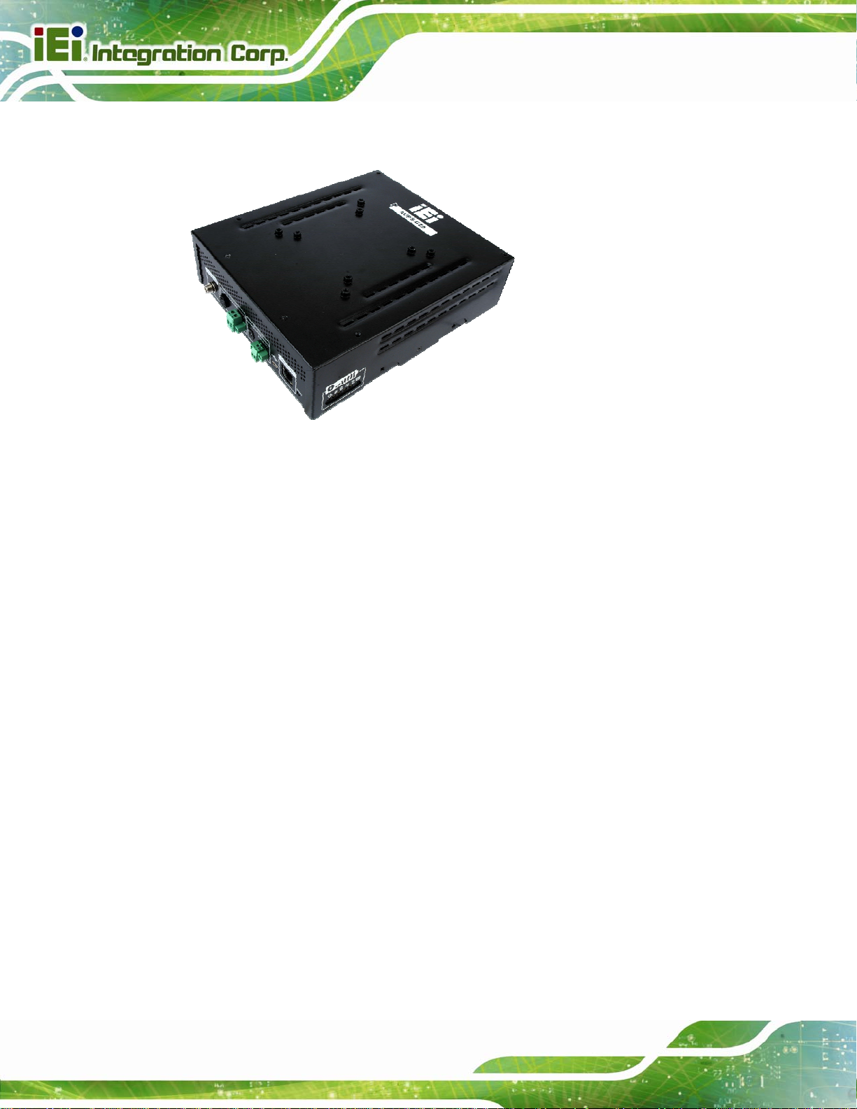
Figure 1-1: AUPS-C20 ....................................................................................................................2
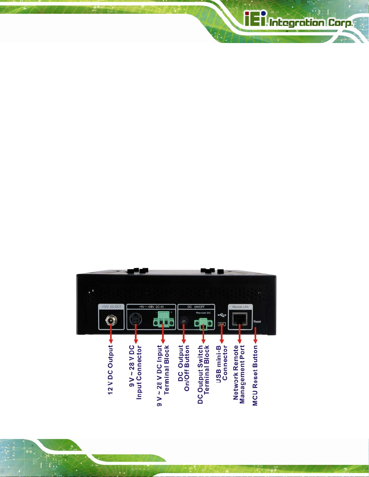
Figure 1-2: AUPS-C20 I/O Interface Connectors .........................................................................3
Figure 1-3: AUPS-C20 LED Indicators..........................................................................................4
Figure 1-4: AUPS-C20 Dimensions (mm).....................................................................................6
Figure 3-1: Top Cover Retention Screws...................................................................................15
Figure 3-2: Battery Board Retention Screws.............................................................................16
Figure 3-3: Battery Bracket Retention Screws..........................................................................16
Figure 3-4: Battery Pack Installation ..........................................................................................17
Figure 3-5: Reinstalling the Battery Bracket and Battery Board.............................................17
Figure 3-6: Battery Pack Installation On The Upper Layer.......................................................18
Figure 3-7: Mounting Bracket Installation..................................................................................19
Figure 3-8: Mounting the AUPS-C20...........................................................................................19
Figure 3-9: AUPS-C20 and Panel PC Connection .....................................................................20
Figure 4-1: Preparing Setup Screen ...........................................................................................22
Figure 4-2: Driver Welcome Screen............................................................................................23
Figure 4-3: Driver License Agreement Screen ..........................................................................23
Figure 4-4: Choose Destination Location ..................................................................................24
Figure 4-5: Ready to Install the Driver........................................................................................24
Figure 4-6: InstallShield Wizard Complete Screen....................................................................25
Figure 4-7: CP210x USB to UART Bridge Driver Installer ........................................................25
Figure 4-8: Installation Complete................................................................................................25
Figure 4-9: Welcome Screen .......................................................................................................26
Figure 4-10: Select Installation Folder........................................................................................27
Figure 4-11: Ready to Install the Program.................................................................................27
Figure 4-12: Installing AUPS .......................................................................................................28
Figure 4-13: Installation Complete..............................................................................................28
Figure 4-14: AUPS Battery Status Monitor Application............................................................29
Figure 4-15: Status Information ..................................................................................................29
Figure 4-16: DC Detection............................................................................................................29
Figure 4-17: Total Battery Time...................................................................................................30
Page vi
Page 7

AUPS-C20 UPS Module
Figure 4-18: Battery Detection ....................................................................................................30
Figure 4-19: Battery Information.................................................................................................31
Figure 4-20: LAN Setting..............................................................................................................32
Figure 4-21: Application Setting .................................................................................................33
Figure 4-22: RJ-45 Remote LAN Connector...............................................................................34
Figure 4-23: IEI REMOTE AP .......................................................................................................35
Figure 4-24: IEI REMOTE AP – IP Address ................................................................................35
Figure 4-25: Remote Management Web Interface - Status.......................................................36
Figure 4-26: Remote Management Web Interface - Send Email ..............................................36
Figure 4-27: Enter User Name and Password............................................................................37
Figure 4-28: Board Configuration...............................................................................................37
Page vii
Page 8

AUPS-C20 UPS Module
List of Tables
Table 1-1: LED Indications.............................................................................................................4
Table 1-2: Total Battery Capacity Indications..............................................................................5
Table 1-3: AUPS-C20 Specifications.............................................................................................7
Table 1-4: AUPS-C20 Battery Specifications...............................................................................8
Table 2-1: Packing List.................................................................................................................12
Page viii
Page 9

AUPS-C20 UPS Module
Chapter
1
1 Introduction
Page 1
Page 10
1.1 Introduction
Figure 1-1: AUPS-C20
AUPS-C20 UPS Module
The highly efficient, high-performance AUPS-C20 UPS (Uninterruptible Power Supply)
module could be installed with four Li-ion batteries to provide stable 12V output and
uninterruptible power to the IEI AFOLUX series panel PCs. The UPS module also
receives a wide range of inputs between 9 V and 28 V DC. The AUPS-C20 is built on an
intelligent design and provides outstanding line and load regulations. The AUPS-C20 is
capable of providing power for certain of time in power failure.
The AUPS-C20 UPS module comes with the utility software that provides information on
current power source and battery status. With the AUPS software installed and network
connected, the AUPS-C20 can be monitored and turned on/off through a remote
computer.
1.2 Features
Some of the AUPS-C20 UPS module features are listed below:
Rugged metal enclosure for standard VESA 75/100 mounting
Wide range power input (9 V ~ 28 V) by DC jack or terminal block
Page 2
100 W power output
Network management through web-based interface in remote computer. No
additional administration software installation is required.
Page 11
AUPS-C20 UPS Module
Supports PC-based utility for monitoring power and battery status
Auto shut down when battery low
Provides stable power to AFOLUX PPC during line sags and spikes
Absorb power surges and transients
1.3 External Overview
1.3.1 I/O Interface Panel
The I/O interface panel contains:
1 x 9 V ~ 28 V DC input connector
1 x 9 V ~ 28 V DC input terminal block
1 x 12 V DC output jack
1 x DC output on/off button
1 x DC output switch terminal block
1 x MCU reset button
1 x Network remote management port (RJ-45)
1 x USB mini-B connector
The I/O interface panel is shown in
Figure 1-2.
Figure 1-2: AUPS-C20 I/O Interface Connectors
Page 3
Page 12
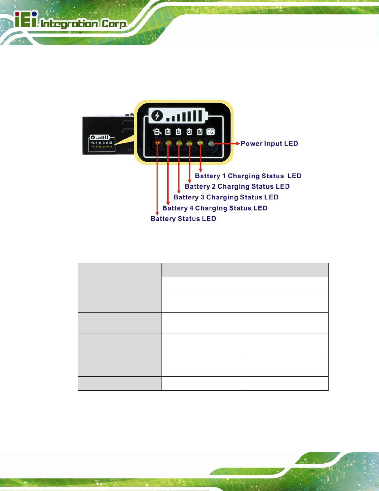
1.3.2 LED Indicators
The side panel of the AUPS-C20 has six LED indicators to indicate the power and battery
AUPS-C20 UPS Module
status (
Figure 1-3).
Figure 1-3: AUPS-C20 LED Indicators
All the LED statuses are listed in
Table 1-1.
LED (Color)/Status On Blinking
Power Input (Green)
Battery 1 Charging Status
(Yellow)
Battery 2 Charging Status
(Yellow)
Battery 3 Charging Status
(Yellow)
Battery 4 Charging Status
(Yellow)
Battery Status (Orange)
Table 1-1: LED Indications
DC power in --
Discharging (battery full) Charging
Discharging (battery full) Charging
Discharging (battery full) Charging
Discharging (battery full) Charging
Battery discharging Battery low
Page 4
Page 13
AUPS-C20 UPS Module
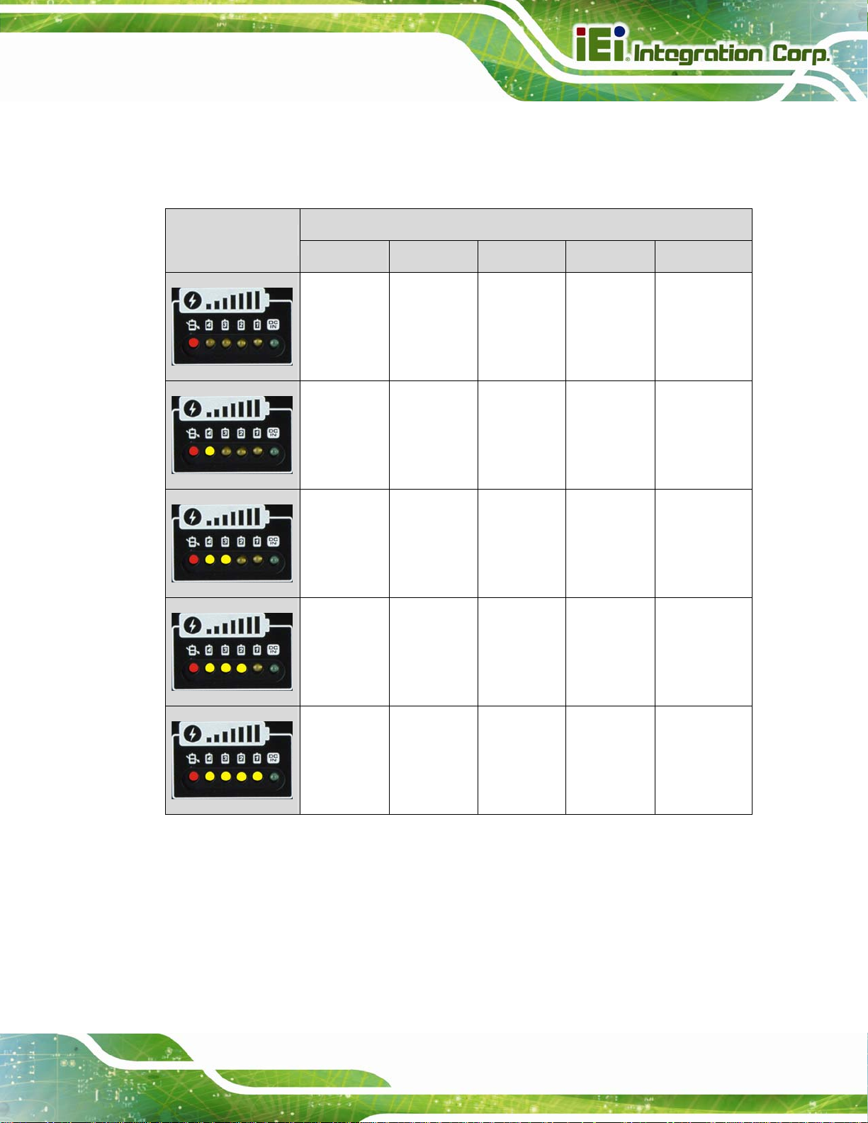
To see the approximate total battery capacity, press the DC output on/off button for four
seconds. The LED indicators will light up, showing the corresponding total battery capacity
as listed in
Table 1-2.
Total Battery Capacity
< 20% 20% ~ 40% 40% ~ 60% 60% ~ 80% 100%
V
V
V
V
V
Table 1-2: Total Battery Capacity Indications
Page 5
Page 14
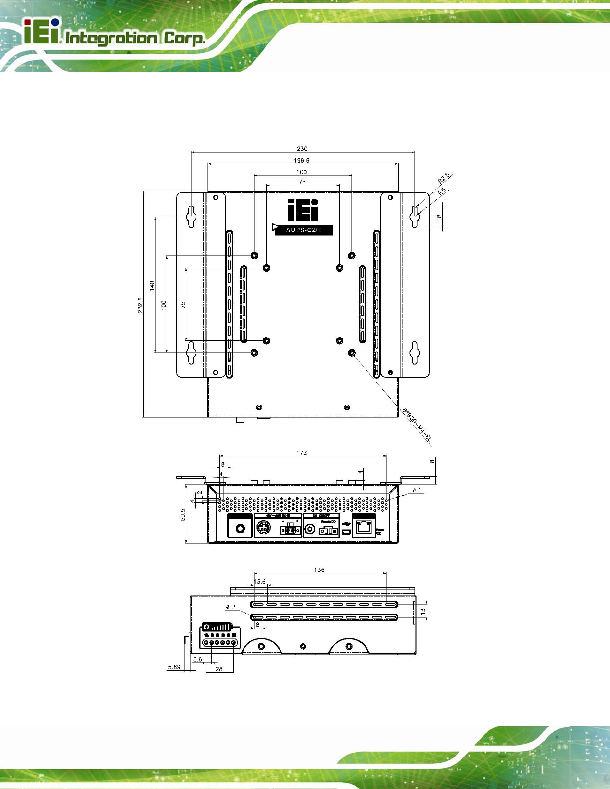
1.4 Dimensions
The main dimensions of the AUPS-C20 are shown in the diagram below.
AUPS-C20 UPS Module
Page 6
Figure 1-4: AUPS-C20 Dimensions (mm)
Page 15

AUPS-C20 UPS Module
1.5 Technical Specifications
The AUPS-C20 technical specifications are listed below.
Specification/Model AUPS-C20
VESA Type
Input voltage
Input
Output
Protection
Regulatory EMC/Safety certification
Monitoring
Standby power
consumption
Charging time
Output voltage
Output current
Battery capacity
Short-circuit protection
Exhaustive discharge
protection
Ethernet interface
USB interface
VESA 75 and VESA 100
DC +9V ~ +28V
0.3A (0.2A if Network Management is disabled)
8~12 hrs
DC +12 V +/-5%
Max. 7.6 A
225 Wh
Yes
Yes
CE, FCC
Web-based, 10/100Mbps
PC-capable, USB 2.0
Dimensions (LxWxH)
Physical
Weight
Green
LED
Environment
Table 1-3: AUPS-C20 Specifications
Yellow
Orange
Operating temperature
Storage temperature
233 mm x 197 mm x 59 mm
3.8 kg
DC power input
Battery charging
Battery discharging
0°C ~ 40°C
-20°C ~ 50°C
Page 7
Page 16

1.6 Battery Specifications
The AUPS-C20 can be installed with four Li-ion smart batteries. The Li-ion battery
AUPS-C20 UPS Module
specifications are listed
below.
Specification/Battery Model BAT-LI-4S2P3800
Battery Type
Nominal Capacity
Nominal Voltage
Max. Charge Voltage
Cut Off Voltage
Recommended Charge Current (Max.)
System Continuous Discharging
Current (Max.)
The End of Charge Condition
Discharge Protection
Li-ion
3800 mAH
14.8 V
16.8 V
11.2 V
2 A
7.6 A
200 mA/min
UVP/OCP
Charge Protection
Self-discharge Rate
Dimensions
Weight
Ambient Temperature
Storage Temperature
Cycle Life
Backup
Safety Class
Table 1-4: AUPS-C20 Battery Specifications
OVP/OCP
340 uA ~ 440 uA
165 mm x 76 mm x 26 mm
450 g
0°C ~ +40°C
-20°C ~ +60°C
300 charge/discharge cycles
100 W/10 min
CE, FCC
Page 8
Page 17

AUPS-C20 UPS Module
Chapter
2
2 Packing List
Page 9
Page 18

2.1 Anti-static Precautions
WARNING!
Static electricity can destroy certain electronics. Make sure to follow the
ESD precautions to prevent damage to the product, and injury to the
user.
Make sure to adhere to the following guidelines:
Wear an anti-static wristband: Wearing an anti-static wristband can prevent
electrostatic discharge.
Self-grounding: Touch a grounded conductor every few minutes to discharge
any excess static buildup.
AUPS-C20 UPS Module
Use an anti-static pad: When configuring any circuit board, place it on an
anti-static mat.
Only handle the edges of the PCB: Don't touch the surface of the
motherboard. Hold the motherboard by the edges when handling.
2.2 Unpacking Precautions
When the AUPS-C20 is unpacked, please do the following:
Follow the antistatic guidelines above.
Make sure the packing box is facing upwards whe n opening.
Make sure all the packing list items are present.
Page 10
Page 19

AUPS-C20 UPS Module
2.3 Packing List
NOTE:
If any of the components listed in the checklist below are missing, do
not proceed with the installation. Contact the IEI reseller or vendor the
AUPS-C20 was purchased from or contact an IEI sales representative
directly by sending an email to sales@ieiworld.com.
The AUPS-C20 is shipped with the following components:
Quantity Item Image
1 AUPS-C20 UPS module
4 Li-ion battery pack (optiona l)
1 Mounting bracket
1 DC output cable (DC plu g to DC plug)
1 DC output cable (DC plu g to 4-pin mini-DIN)
1 Power transfer ca ble (DC plug to 4-pin
mini-DIN)
Page 11
Page 20

Quantity Item Image
1 DC output switch cable
1 USB Type A to mini-B cable
1 Screw kit
2 Wall mount bracket
1 Utility software CD
AUPS-C20 UPS Module
Table 2-1: Packing List
Page 12
Page 21

AUPS-C20 UPS Module
Chapter
3
3 Installation
Page 13
Page 22

3.1 Anti-static Precautions
AUPS-C20 UPS Module
Electrostatic discharge (ESD) can cause serious damage to electronic components,
including the AUPS-C20. Dry climates are especially susceptible to ESD. It is therefore
critical that whenever the AUPS-C20 or any other electrical component is handled, the
following anti-static precautions are strictly adhered to.
WARNING:
Failure to take ESD precautions during the installation of the
AUPS-C20 may result in permanent damage to the AUPS-C20 and
severe injury to the user.
Wear an anti-static wristband: - Wearing a simple anti-static wristband can
help to prevent ESD from damaging the board.
Self-grounding:- Before handling the board touch any grounded conducting
material. During the time the board is handled, frequently touch any
conducting materials that are connected to the ground.
Use an anti-static pad: When configuring the AUPS-C20, place it on an
antic-static pad. This reduces the possibility of ESD damaging the AUPS-C20.
Only handle the edges of the PCB:-: When handling the PCB, hold the PCB
by the edges.
3.2 Installation Precautions
When installing the power module, please follow the precautions listed below:
Power turned off: When installing the power module, make sure the power i s
off. Failing to turn off the power may cause severe injury to the body and/or
damage to the system.
Certified Engineers: Only certified engineers should install and modify
onboard functionalities.
Anti-static Discharge : If a user open the top cover of the power module, to
configure the jumpers or plug in added peripheral devices, ground themselves
first and wear an anti-static wristband.
Page 14
Page 23

AUPS-C20 UPS Module
3.3 Installation and Configuration Steps
The following installation steps must be followed.
Step 1: Unpack the UPS module
Step 2: Install the battery packs
Step 3: Mount UPS module to the AFOLUX panel PC
Step 4: Connect the UPS module to the AFOLUX panel PC
3.4 Installing the Battery Packs
NOTE:
Before installing the battery packs into the AUPS-C20, it is
recommended to press the MCU reset button to return the AUPS-C20
to the factory default settings.
The AUPS-C20 could be installed up to four battery packs. To install the battery packs,
follow the steps below.
Step 1: Remove the six top cover retention screws (
the AUPS-C20 module.
Figure 3-1) and lift the top cover off
Figure 3-1: Top Cover Retention Screws
Page 15
Page 24

Step 2: Remove the five battery board retention screws (Figure 3-2) and lift the battery
board off the AUPS-C20 module.
Figure 3-2: Battery Board Retention Screws
AUPS-C20 UPS Module
Step 3: Remove the six battery bracket retention screws (
bracket off the AUPS-C20 module.
Figure 3-3: Battery Bracket Retention Screws
Figure 3-3) and lift the battery
Page 16
Page 25

AUPS-C20 UPS Module
Step 4: Install battery 1 and battery 2 into the AUPS-C20 (Figure 3-4). Make sure the
battery packs are connected to the battery connectors on the board (
3-4).
Figure 3-4: Battery Pack Installation
Figure
Step 5: Secure each battery pack with two retention screws (
Step 6: Replace the battery bracket and battery board (
Figure 3-5: Reinstalling the Battery Bracket and Battery Board
Figure 3-4).
Figure 3-5).
Page 17
Page 26

Step 7: Install battery 3 and battery 4 into the AUPS-C20 (Figure 3-6). Make sure the
battery packs are connected to the battery connectors on the battery board
Figure 3-6).
(
AUPS-C20 UPS Module
Figure 3-6: Battery Pack Installation On The Upper Layer
Step 8: Secure each battery pack with two retention screws (
Step 9: Replace the top cover.
3.5 Mounting the AUPS-C20
To mount the AUPS-C20 onto the rear panel of the AFOLUX panel PC, follow the steps
below.
Step 1: Install the mounting bracket onto the rear panel of the AFOLUX panel PC.
Align the screw holes in the mounting bracket with the VESA screw holes in the
rear of the panel PC. Secure the mounting bracket to the panel PC with four
retention screws (
Figure 3-7).
Figure 3-6).
Page 18
Page 27

AUPS-C20 UPS Module
Figure 3-7: Mounting Bracket Installation
Step 2: Install the AUPS-C20 onto the rear panel of the AFOLUX panel PC. Place
the AUPS-C20 onto the mounting bracket. Secure the AUPS-C20 to the bracket
with five retention screws, one on the rear panel and two on each side panel
Figure 3-8).
(
Figure 3-8: Mounting the AUPS-C20
Page 19
Page 28

3.6 Connecting the AUPS-C20
To support the UPS function to the panel PC, the AUPS-C20 must be connected to the
AUPS-C20 UPS Module
power source and to the panel PC.
Figure 3-9 shows the connections.
Figure 3-9: AUPS-C20 and Panel PC Connection
Page 20
Page 29

AUPS-C20 UPS Module
4 Software Application
Chapter
4
Page 21
Page 30

4.1 Introduction
The IEI AUPS Battery Status Monitor application detects the information of the smart
battery and monitors the battery status.
4.2 Monitoring DC Power and Smart Battery
4.2.1 Driver Installation
Follow the steps below to install the necessary drivers.
Step 1: Insert the driver CD into the system. Open the x:\Driver directory. Double click
the CP210x_VCP_Win_XP_S2K3_Vista_7 icon.
AUPS-C20 UPS Module
The InstallShield Wizard prepares the setup as shown (
Figure 4-1: Preparing Setup Screen
Figure 4-1).
Page 22
Page 31

AUPS-C20 UPS Module
Step 2: A welcome screen appears (Figure 4-2). To continue the installation process
click Next.
Figure 4-2: Driver Welcome Screen
Step 3: The license agreement in
Check I accept the terms of license agreement and click Next to continue.
Figure 4-3: Driver License Agreement Screen
Figure 4-3 appears. Read the License Agreement.
Page 23
Page 32

Step 4: The Choose Destination Location window appears (Figure 4-4). Select a folder
to install the driver.
Figure 4-4: Choose Destination Location
AUPS-C20 UPS Module
Step 5: Click Next and the InstallShield Wizard i s ready to inst all the d river (
Step 6: Click Install to start the installation.
Figure 4-5: Ready to Install the Driver
Figure 4-5).
Page 24
Page 33

AUPS-C20 UPS Module
Step 7: The InstallShield Wizard Complete window appears (Figure 4-6). Check
Launch the CP210x VCP Driver Installer and click Finish to launch the
CP210x USB to UART Bridge Driver Installer.
Figure 4-6: InstallShield Wizard Complete Screen
Step 8: Click Install to start inst alling the CP210x USB to UART Bridge driver (
4-7).
Figure 4-7: CP210x USB to UART Bridge Driver Installer
Step 9: When the installation is complete, the screen in
Finish to exit.
Figure 4-8 appears. Click
Figure
Figure 4-8: Installation Complete
Page 25
Page 34

4.2.2 Application Installation
Follow the steps below to install the AUPS Battery Status Monitor application.
Step 1: Insert the driver CD into the system. Open the x:\AUPS_2.6_setup\
AUPS_SetupV2.6 directory. Double click the AUPS_Setup v2.6 icon.
AUPS-C20 UPS Module
Step 2: A welcome screen appears (
click Next.
Figure 4-9: Welcome Screen
Figure 4-9). To continue the installation process,
Page 26
Page 35

AUPS-C20 UPS Module
Step 3: The Select Installation Folder window appears (Figure 4-10). Select a folder to
install the application.
Figure 4-10: Select Installation Folder
Step 4: Click Next and the Installshield Wizard is ready to install the program (
4-11).
Figure
Figure 4-11: Ready to Install the Program
Page 27
Page 36

Step 5: Click Next to continue. The Installing AUPS_Setup screen appears as the
AUPS-C20 UPS Module
program is installed (
Figure 4-12: Installing AUPS
Step 6: The Installation Complete window appears (
Figure 4-12).
Figure 4-13). Click Close to exit.
Page 28
Figure 4-13: Installation Complete
Page 37

AUPS-C20 UPS Module
Step 7: To launch the application, double click the shortcut (Figure 4-14) on the
desktop.
Figure 4-14: AUPS Battery Status Monitor Application
4.2.3 Status Information
The IEI AUPS Battery Status Monitor application shows the DC power status and battery
status (
Figure 4-15: Status Information
Figure 4-15). The following sections describe the status information in details.
4.2.3.1 DC Detection
When the DC power is connected to the AUPS-C20 power module, the AUPS Battery
Status Monitor detects it and shows in the screen as
Figure 4-16: DC Detection
Figure 4-16.
Page 29
Page 38

4.2.3.2 Total Battery Time
The total battery time is shown in the top right corner (Figure 4-17) of the status screen to
indicate the total battery remaining time.
Figure 4-17: Total Battery Time
4.2.3.3 Battery Detection
Four batteries can be connected to the AUPS-C20 power module at the same time. When
the smart battery is connected to the AUPS-C20 power module, the AUPS Battery Status
AUPS-C20 UPS Module
Monitor detects it and shows in the screen as
right of the status screen to display its battery information.
Figure 4-18. Click the battery number on the
Figure 4-18: Battery Detection
The battery is connected to the AUPS-C20.
Off The battery is not connected to the AUPS-C20.
Page 30
Full The battery is fully charged.
Low The battery is low.
Page 39

AUPS-C20 UPS Module
Using The battery is being used.
Charging The battery is being charged.
Standby The battery is fully charged and ready to be used anytime.
4.2.4 Battery Information
Click the BATTERY tab to view the information of the connected batteries. Click the
battery number on the right side of the battery screen to display its battery information.
The listed information includes battery type, capacity, output voltage, temperature,
The battery temperature is above 60°C.
The battery temperature is below 60°C.
charging rate, discharging rate and battery status (
updated per second.
Figure 4-19: Battery Information
Figure 4-19). The values listed are
Page 31
Page 40

4.2.5 LAN Setting
The LAN Setting page is where to configure the Remote LAN settings for power on/off
remote control and battery monitoring. To save the modified parameters of this p age, cli ck
the Save Config button. To load the default settings, click the Load Default button.
AUPS-C20 UPS Module
Figure 4-20: LAN Setting
Page 32
Page 41

AUPS-C20 UPS Module
4.2.6 Setting
Click the SETTING tab to enable/disable buzzer, LAN and automatic DC output (Figure
4-21).
Figure 4-21: Application Setting
Functions can be set in the SETTING tab include:
Check to disable the buzzer that warns when the system is switching to
Set the battery capacity parameter for the system to shut down automatically. In this case, the
system will shut down automatically when the battery capacity is below 5%.
use battery power.
Check to enable the LAN for remote monitoring function.
Check to enable the remote computer to turn the system power on or
off.
Check to enable the AUPS-C20
power adapter is connected to the AUPS-C20.
to output power automatically when a
Set the power off delay time in seconds.
Page 33
Page 42

4.3 Remote Control and Monitoring
The AUPS-C20 can be controlled (power on/off) and monitored the battery status through
a remote computer located in the same subnet with the AUPS-C20. To control and
monitor the AUPS-C20 remotely, follow the steps below.
Step 1: Connect the RJ-45 remote LAN connector on the I/O interface panel of the
AUPS-C20 UPS Module
AUPS-C20 (
Figure 4-22: RJ-45 Remote LAN Connector
Step 2: In a remote computer, install the IEI REMOTE AP. Double click the
AUPS_REMOTE_APv14 file in the x:\AUPS_REMOTE_APv14 directory.
Follow the steps to install the IEI REMOTE AP. After installation, launch the AP. If
there is a problem to launch the tool, execute the dotnetfxRedist20.exe first
(located in the same directory of the driver CD).
Figure 4-22) to a local area network connector.
Page 34
Step 3: The IEI REMOTE AP tool appears (
the same subnet with this remote computer are shown in the list on the right.
Click the function buttons on the left to control the AUPS-C20.
Figure 4-23). All the AUPS-C20 modules in
Page 43

AUPS-C20 UPS Module
Figure 4-23: IEI REMOTE AP
Step 4: To access the web interface for advanced monitoring and function s, double click
the IP address of the connected AUPS-C20 (
Figure 4-24: IEI REMOTE AP – IP Address
Step 5:
Figure 4-25 shows in a web browser.
Figure 4-24).
Page 35
Page 44

Figure 4-25: Remote Management Web Interface - Status
Step 6: To send an email to an administrator through the SMTP server, cli ck Send
AUPS-C20 UPS Module
E-mail button on the left. Fill out the information as indicated in
Click the Send Message button to send the email.
Figure 4-26: Remote Management Web Interface - Send Email
Figure 4-26.
Page 36
Step 7: To configure the AUPS-C20 network setting, click the Configuration button on
the left.
Page 45

AUPS-C20 UPS Module
Step 8: A window pro m pts for the user name and password. The default user name and
password for the LAN setting page are:
User name: admin
Password: IEI
Figure 4-27: Enter User Name and Password
Step 9: The Board Configuration window appears. Configure the network settings and
click the Save Config button. Incorrect settings may cause the board to lose
network connectivity.
Figure 4-28: Board Configuration
Page 37
Page 46

AUPS-C20 UPS Module
Appendix
A
A Safety Precautions
Page 38
Page 47

AUPS-C20 UPS Module
DANGER!
1. Disassemble and Reconstruction
“Do not disassemble or reconstruct battery”
The battery pack has safety function and protection circuit to avoid the danger. If they have
serious damage, it will cause the generating heat, smoke, rupture or flame.
2. Short-circuit
“Do not short-circuit battery”
Do not connect the + and – terminals with metals (such as wire). Do not carry or store the
battery with metal objects (such as wire , necklace or hairpins). If the battery is short-circuited,
excessive large current will flow and then the generating heat, smoke, rupture of flame will
occur. And also, it causes generating heat at metals.
3. Incineration and Heating
“Do not incinerate or heat the battery”
These occur the melting of insulator, damage of gas release vent or safety function, or ignition
on electrolyte. Above mentioned matte rs cause the generating heat, smoke, rupture or flame.
4. Use Nearby Heated Place
“Do not use or leave battery nearby the fire, stove or heated place (more than 80
In case that separator made of polymer is melted by high temperature, the internal short-circuit
occurs in individual cells and then it causes the generating heat, smoke, rupture or flame. In
addition, do not use the battery under the heated place (more than 80℃) for same reason.
5. Immersion
“Do not immerse the battery in water or sea water, or get it wet”
If the protection circuit included in the battery is broken, the battery will be charged at extreme
current or voltage and the abnormal chemical reaction occurs in it. And then it causes the
generating heat, smoke, rupture or flame.
6. Charge Nearby Heated Place
“Do not charge battery nearby the fire or under the blazing sun”
If the protection circuit to avoid the danger works under high temperature or it is broken, the
battery will be charged at abnormal current (or voltage) and abnormal chemical reaction will
occur. It caused the generating heat, smoke, rupture or flame.
℃
)”
7. Charger and Charge Condition
“Do use the specified charger and observe charging requirement”
If the battery is charged with unspecified condition (under high temperature over t he regulated
value, excessive high voltage or current over regulated value, or remodeled charger), there
Page 39
Page 48

are cases that it will be overcharged or the abnormal chemical reaction will occur in cells. It
caused the generating heat, smoke, rupture or flame.
8. Penetration
“Do not drive a nail into the battery, strike it by hammer, or tread it”
As the battery might be broken or deformed and then it will be short-circuited, it caused the
generating heat, smoke, rupture or flame.
9. Impact
“Do not give battery impact or throw it”
The impact might cause leakage, heat, smoke, rupture, and/or fire of cell in the battery. And
also if the protection circuit in the battery is broken, the battery will be charged at abnormal
voltage or current, and abnormal chemical reaction might occur. It might cause leakage, heat,
smoke rupture, and/or fire.
10. Deformation
“Do not use the battery with conspicuous damage or deformation”
AUPS-C20 UPS Module
It causes the generating heat, smoke, rupture or flame.
11. Soldering
“Do not make the direct soldering on battery”
As the insulator is melted by heat or the gas release vent (or safety function) is broken, it
caused the generating heat, smoke, rupture or flame.
12. Reverse Charge and Overdischarge
“Do not reverse polarity (and terminals)”
On charging, the battery is reverse-charged and abnormal chemical reaction occurs. And also,
there may be case that unexpected large current flows on discharging. These cause the
generating heat, smoke, rupture or flame.
13. Reversed Polarity Use
“Do not reverse-charge or reverse-connect”
The battery has polarity. In case the battery is not connected with charger or equipment
smoothly, do not force them to connect and do check polarity of battery. If the battery is
connected to opposite polarity with charger, it will be reverse-charged and abnormal chemical
reaction will occur. It causes the gen erating heat, smoke, rupture or flame.
14. Connect Battery to the Plug
“Do not connect battery to the plug socket or car-cigarette-plug”
Added high voltage to the battery, the excessive current will flow in it and then it will cause the
generating heat, smoke, rupture or flame.
Page 40
Page 49

AUPS-C20 UPS Module
15. Inappropriate Use for Other Equipment
“Do not use battery for other equipment”
If the battery is used for unspecified equipment, it will deteriorate its performance and cy cle-life.
At worst, abnormal current will flow or battery may generate heat, smoke, rupture or flame.
16. Leakage
“Do not touch a leaked battery directly”
In case the leaked electrolyte gets into eyes, wash them with fresh water as soon as possible
without rubbing eyes. And then, see a doctor immediately.
If leave damaged eyes undone, it will cause eye-trouble.
WARNING:
1. Mixed Use
“Do not use Lithium ion battery in mixture”
Do not use Lithium ion battery with the primary batteries or secondary batteries whose
capacity kind or maker is different, if do that, the battery will be discharged or charged
excessively in use. And it may cause the generat ing, smoke, rupture or flami ng because of the
abnormal chemical reaction in cells.
2. Ingestion
“Keep the battery away from babies”
Keep the little battery out of the reach of babies in order to avoid troubles by swallowing. In
case of swallowing the battery, see a doctor immediately.
3. Charging Time
“Do not continue to charge battery over specified time”
If the battery is not finished charging over regulated time, let it stop charging. There is
possibility that the battery might generate, smoke, rupture or flame.
4. Store
“Do not get into a microwave or a high pressure conta iner”
It causes the generating, smoke, rapture or flaming because of a sudden heat or damage of
sealing condition of battery.
5. Leakage
“Do not use a leaked battery nearby fire”
If the liquid leaks from the battery (or the battery gives out bad smell), let the battery leave
from flammable objects immediately. Unless do that, the electrolyte leaked from battery will
catch fire and it will cause the smoke, flaming or rupture of it.
Page 41
Page 50

6. Rust, Changing Color and Deformation
“Do not use an abnormal battery”
In case the battery has bad smell or is generated its changing col or or deformation or causes
something wrong in using (includes charging and storage), let it take out from equipment or
charger and do not use it. If an abnormal battery is used, it will generate, smoke, rupture or
flame.
AUPS-C20 UPS Module
CAUTION:
1. Use Under Strong Sunshine
Do not use or leave the battery under the blazing sun (or heated car by sunshin e). The b attery
may generate heat, smoke or flame. And also, it might cause the deterioration of battery’s
characteristics or cycle life.
2. Static Electricity
The battery has the protection circuit to avoid the danger. Do not use nearby the place where
generates static electricity (more than 100 V) which gives damage to the protection circuit. If
protection circuit were broken, the battery would generate, smoke, rupture or flame.
3. Charging Temperature Range
Charging temperature rage is regulated 0℃ and 40℃. Do not charge the battery out of
recommended temperature range. Charging out of recommended range might cause the
generating heat or serious damage of battery. And also, it might cause the deterioration of
battery’s characteristics and cycle life.
4. Manual
Please read the manual before using the battery and keep it after reading.
5. Charging Method
Please read the manual of specified charger about charging method.
6. First Time Use
When the battery has rust, bad smell or something abnormal at first -time-using, d o not use the
equipment and bring the battery to the shop from which it was purchased.
7. Used By Children
In case younger children use the battery, their parents teach how to use batteries according to
the manual with care. And also, when children are using the batteries, pay attention to use it
according to that or not.
Page 42
Page 51

AUPS-C20 UPS Module
8. Keep Battery Away From Children
Keep the battery out of the reach of younger children. And also, pay attention when the battery
is taken out from the charger or equipment by little children.
9. Leakage
If the skin or cloth is smeared with liquid from the battery, wash with fresh water. It may cause
the skin inflammation.
Page 43
Page 52

AUPS-C20 UPS Module
Appendix
B
B Hazardous Materials
Disclosure
Page 44
Page 53

AUPS-C20 UPS Module
B.1 Hazardous Materials Disclosure Table for IPB Products
Certified as RoHS Compliant Under 2002/95/EC Without
Mercury
The details provided in this appendix are to ensure that the product is compliant with the
Peoples Republic of China (China) RoHS standards. The table below acknowledges the
presences of small quantities of certain materials in the product, and is appli cable to China
RoHS only.
A label will be placed on each product to indicate the estimated “Environmentally Friendly
Use Period” (EFUP). This is an estimate of the number of years that these substances
would “not leak out or undergo abrupt change.” This product may contain replaceable
sub-assemblies/components which have a shorter EFUP such as batteries and lamps.
These components will be separately marked.
Please refer to the table on the next page.
Page 45
Page 54

Toxic or Hazardous Substances and Elements Part Name
AUPS-C20 UPS Module
Housing
Display
Printed Circuit
Board
Metal
Fasteners
Cable
Assembly
Fan Assembly
Power Supply
Assemblies
Lead
(Pb)
O O O O O O
O O O O O O
O O O O O O
O O O O O O
O O O O O O
O O O O O O
O O O O O O
Mercury
(Hg)
Cadmium
(Cd)
Hexavalent
Chromium
(CR(VI))
Polybrominated
Biphenyls
(PBB)
Polybrominated
Diphenyl
Ethers
(PBDE)
Battery
O: This toxic or hazardous substance is cont aine d in all of the homogeneo us mate rials for the p a rt is
below the limit requirement in SJ/T11363-2006
X: This toxic or hazardous substance is contained in at least one of the homogeneous materials for
this part is above the limit requirement in SJ/T11363-2006
O O O O O O
Page 46
Page 55

AUPS-C20 UPS Module
此附件旨在确保本产品符合中国 RoHS 标准。以下表格标示此产品中某有毒物质的含量符
合中国 RoHS 标准规定的限量要求。
本产品上会附有”环境友好使用期限”的标签,此期限是估算这些物质”不会有泄漏或突变”的
年限。本产品可能包含有较短的环境友好使用期限的可替换元件,像是电池或灯管,这些元
件将会单独标示出来。
部件名称
壳体
显示
印刷电路板
金属螺帽
电缆组装
风扇组装
电力供应组装
电池
O: 表示该有毒有害物质在该部件所有物质材料中的含量均在 SJ/T11363-2006 标准规定的限量要求以下。
X: 表示该有毒有害物质至少在该部件的某一均质材料中的含量超出 SJ/T11363-2006 标准规定的限量要求。
有毒有害物质或元素
铅
(Pb)
O O O O O O
O O O O O O
O O O O O O
O O O O O O
O O O O O O
O O O O O O
O O O O O O
O O O O O O
汞
(Hg)
镉
(Cd)
六价铬
(CR(VI))
多溴联苯
(PBB)
多溴二苯
醚
(PBDE)
Page 47
 Loading...