

Page 1
User Manual
AFL2-W15B-H61
MODEL:
AFL2-W15B-H61 Series
Flat Bezel Panel PC with 2nd Generation Intel® Core™ i7/ i5/ i3,
Pentium® and Celeron® Processor, Touchscreen, Wi-Fi, USB,
GbE LAN , RS-232/422/485, 1.3M Pixels Camera,
HD Audio and RoHS
User Manual
Rev. 1.01 - 25 July, 2013
Page I
Page 2

Date Version Changes
AFL2-W15B-H61
Revision
25 July, 2013 1.01
13 September, 2012 1.00
Added information of the CPU temperature alert LED in Section
Updated Section
Initial release
8.3.7: RS-422/485 RJ-45 Serial Port (COM3)
1.2.1.1.
Page II
Page 3

AFL2-W15B-H61
COPYRIGHT NOTICE
The information in this document is subject to change without prior notice in order to
improve reliability, design and function and does not represent a commitment on the part
of the manufacturer.
In no event will the manufacturer be liable for direct, indirect, special, incidental, or
consequential damages arising out of the use or inability to use the product or
documentation, even if advised of the possibility of such damages.
This document contains proprietary information protected by copyright. All rights are
Copyright
reserved. No part of this manual may be reproduced by any mechanical, electronic, or
other means in any form without prior written permission of the manufacturer.
TRADEMARKS
All registered trademarks and product names mentioned herein are used for identification
purposes only and may be trademarks and/or registered trademarks of their respective
owners.
Page III
Page 4

AFL2-W15B-H61
Table of Contents
1 INTRODUCTION.......................................................................................................... 1
1.1 OVERVIEW.................................................................................................................. 2
1.1.1 Model Variations................................................................................................ 3
1.1.2 Features ............................................................................................................. 4
1.1.3 Light Fanless Technology Design...................................................................... 4
1.2 EXTERNAL OVERVIEW................................................................................................ 4
1.2.1 Front Panel........................................................................................................ 4
1.2.1.1 LED Indicators............................................................................................ 5
1.2.1.2 Function Keys............................................................................................. 7
1.2.2 Rear Panel ......................................................................................................... 8
1.2.3 Bottom Panel...................................................................................................... 9
1.2.4 Side Panels....................................................................................................... 10
1.3 DIMENSIONS..............................................................................................................11
1.4 INTERNAL OVERVIEW............................................................................................... 12
1.5 SYSTEM SPECIFICATIONS.......................................................................................... 13
2 UNPACKING............................................................................................................... 15
2.1 UNPACKING.............................................................................................................. 16
2.1.1 Packing List ..................................................................................................... 16
3 INSTALLATION ......................................................................................................... 20
3.1 ANTI-STATIC PRECAUTIONS...................................................................................... 21
3.2 INSTALLATION PRECAUTIONS ................................................................................... 21
3.3 INST ALLATION AND CONFIGURATION STEPS............................................................. 22
3.4 HDD INSTALLATION................................................................................................. 22
3.5 CF CARD INSTALLATION .......................................................................................... 25
3.6 RFID READER INSTALLATION (OPTIONAL) .............................................................. 26
3.7 AT/ATX MODE SELECTION...................................................................................... 28
3.7.1 AT Power Mode................................................................................................ 28
3.7.2 ATX Power Mode............................................................................................. 28
3.8 CLEAR CMOS.......................................................................................................... 29
Page IV
Page 5

AFL2-W15B-H61
3.9 RESET THE SYSTEM.................................................................................................. 29
3.10 POWERING ON THE SYSTEM................................................................................... 30
3.11 POWERING OFF THE SYSTEM.................................................................................. 30
3.12 MOUNTING THE SYSTEM ........................................................................................ 30
3.12.1 Wall Mounting................................................................................................ 31
3.12.2 Panel Mounting.............................................................................................. 34
3.12.3 Cabinet and Rack Installation ....................................................................... 35
3.12.4 Arm Mounting ................................................................................................ 38
3.12.5 Stand Mounting.............................................................................................. 40
3.13 EXTERNAL PERIPHERAL DEVICE CONNECTION ...................................................... 40
3.13.1 Audio Connection........................................................................................... 41
3.13.2 HDMI Device Connection.............................................................................. 42
3.13.3 LAN Connection............................................................................................. 43
3.13.4 Serial Device Connection .............................................................................. 44
3.13.4.1 DB-9 Serial Port Connection.................................................................. 44
3.13.4.2 RJ-45 Serial Port Connection.................................................................. 45
3.13.5 Type K T emperatur e Sensor Connection........................................................ 46
3.13.6 USB Device Connection................................................................................. 47
3.13.7 VGA Monitor Connection .............................................................................. 48
4 BIOS SETUP................................................................................................................ 49
4.1 INTRODUCTION......................................................................................................... 50
4.1.1 Starting Setup................................................................................................... 50
4.1.2 Using Setup...................................................................................................... 50
4.1.3 Getting Help..................................................................................................... 51
4.1.4 Unable to Reboot after Configuration Changes.............................................. 51
4.1.5 BIOS Menu Bar................................................................................................ 51
4.2 MAIN........................................................................................................................ 52
4.3 ADVANCED............................................................................................................... 53
4.3.1 ACPI Settings................................................................................................... 54
4.3.2 RTC Wake Settings ........................................................................................... 55
4.3.3 T rusted Computing........................................................................................... 57
4.3.4 CPU Configuration.......................................................................................... 57
4.3.4.1 CPU Information....................................................................................... 58
4.3.5 SATA Configuration ......................................................................................... 60
Page V
Page 6

4.3.6 Intel TXT (LT) Configuration........................................................................... 61
4.3.7 USB Configuration........................................................................................... 62
4.3.8 F81216 Super IO Configuration...................................................................... 63
4.3.8.1 Serial Port n Configuration....................................................................... 64
4.3.8.1.1 Serial Port 1 Configuration................................................................ 64
4.3.8.1.2 Serial Port 2 Configuration................................................................ 65
4.3.8.1.3 Serial Port 3 Configuration................................................................ 66
4.3.9 H/W Monitor.................................................................................................... 67
4.3.10 Serial Port Console Redirection.................................................................... 69
4.4 IEI FEATURE ............................................................................................................. 71
4.5 CHIPSET ................................................................................................................... 72
4.5.1 Northbridge Configuration.............................................................................. 73
4.5.2 Southbridge Configuration .............................................................................. 74
4.5.3 Integrated Graphics......................................................................................... 77
AFL2-W15B-H61
4.5.4 ME Subsystem.................................................................................................. 79
4.6 BOOT........................................................................................................................ 80
4.7 SECURITY................................................................................................................. 82
4.8 SAVE & EXIT............................................................................................................ 83
5 SOFTWARE DRIVERS.............................................................................................. 85
5.1 AVAILABLE SOFTWARE DRIVERS.............................................................................. 86
5.2 ST ARTING THE DRIVER PROGRAM ............................................................................ 86
5.3 CHIPSET DRIVER INSTALLATION............................................................................... 87
5.4 GRAPHICS DRIVER INSTALLATION............................................................................ 91
5.5 LAN DRIVER INSTALLATION.................................................................................... 95
5.6 AUDIO DRIVER INSTA LLATION ................................................................................. 97
5.7 TOUCH SCREEN DRIVER......................................................................................... 100
5.7.1 Calibrating the Touch Screen......................................................................... 103
5.8 WI-FI DRIVER INSTALLATION................................................................................. 105
5.9 USB 3.0 DRIVER INSTALLATION ............................................................................ 109
6 SYSTEM MONITORING: ICMC............................................................................112
6.1 IEI COOLING MANAGEMENT CONSOLE (ICMC) .....................................................113
6.1.1 iCMC Installation ...........................................................................................113
6.2 ICMC OVERVIEW....................................................................................................116
Page VI
Page 7

AFL2-W15B-H61
6.2.1 Information Panel...........................................................................................116
6.2.2 Chart Panel.....................................................................................................119
7 SYSTEM MAINTENANCE ..................................................................................... 121
7.1 SYSTEM MAINTENANCE INTRODUCTION ................................................................ 122
7.2 ANTI-STATIC PRECAUTIONS.................................................................................... 122
7.3 TURN OFF THE POWER............................................................................................ 123
7.4 OPENING THE SYSTEM............................................................................................ 123
7.4.1 Removing the Back Cover.............................................................................. 123
7.4.2 Removing the Internal Aluminum Cover........................................................ 124
7.5 REPLACING COMPONENTS...................................................................................... 125
7.5.1 Memory Module Replacement ....................................................................... 125
7.5.2 WLAN Card Replacement.............................................................................. 127
7.6 REINST ALLING THE COVERS................................................................................... 129
8 INTERFACE CONNECTORS................................................................................. 130
8.1 PERIPHERAL INTERFACE CONNECTORS................................................................... 131
8.2 INTERNAL PERIPHERAL CONNECTORS .................................................................... 132
8.2.1 Auto-dimming Connector (JP7)..................................................................... 133
8.2.2 Battery Connector (BAT2)............................................................................. 133
8.2.3 Bluetooth USB Connector (BLUETOOTH1)................................................. 134
8.2.4 EC Debug Connector (CN15)........................................................................ 134
8.2.5 Fan Connector (CPU_FAN1)......................................................................... 134
8.2.6 HDD Connector (JSATA3)............................................................................. 135
8.2.7 Hot Key LED Connector (HOTKEYLEDCN1).............................................. 135
8.2.8 Hot Key Connector (HOTKEYCN1).............................................................. 135
8.2.9 LED Indicator Connector (LEDCN1)............................................................ 136
8.2.10 Logo LED Connector (LOGO_LED)........................................................... 136
8.2.11 LVDS Connector (LVDS1) ........................................................................... 136
8.2.12 LVDS Backlight Connector (INVERTER1).................................................. 137
8.2.13 Microphone Connector (DMIC1)................................................................ 137
8.2.14 Mini USB Connector (MINUSB1) ............................................................... 138
8.2.15 Mini USB Connector (MINUSB2) ............................................................... 138
8.2.16 Power Button Connector (PW_BT1) ........................................................... 138
8.2.17 RFID USB Connector (RFIDUSB1)............................................................ 139
Page VII
Page 8

8.2.18 SATA Connector (SATA1)............................................................................. 139
8.2.19 SATA Power Connector (CN8)..................................................................... 139
8.2.20 Speaker Connector (SPK_CN13)................................................................. 140
8.2.21 SPI Flash Connector (JSPI1)....................................................................... 140
8.2.22 EC SPI Flash Connector (JSPI2) ................................................................ 140
8.2.23 Touch Panel Connector (TS1)...................................................................... 141
8.2.24 TPM Connector (TPM1).............................................................................. 141
8.2.25 Type K Thermocouple Connector (CN13, CN14) ........................................ 142
8.2.26 Webcam Connector (WEBCAMER1) ........................................................... 142
8.3 EXTERNAL INTERFACE PANEL CONNECTORS .......................................................... 142
8.3.1 Audio Mic-in Jack (MIC1)............................................................................. 143
8.3.2 Audio Lline-out Jack (LINE_OUT1).............................................................. 143
8.3.3 Ethernet Connector (LAN2)........................................................................... 143
8.3.4 HDMI Connector (HDMI1)........................................................................... 144
AFL2-W15B-H61
8.3.5 Power Connector (PWR1) .......................................................................... 144
8.3.6 RS-232 Serial Ports (COM1, COM2)............................................................ 144
8.3.7 RS-422/485 Serial Port (COM3) ................................................................... 145
8.3.8 USB 2.0 Connectors (USB01)........................................................................ 145
8.3.9 USB 2.0 Connector (USB23) ......................................................................... 146
8.3.10 USB 3.0 Connectors (USB3_12).................................................................. 146
8.3.1 1 VGA Connector (VGA1)............................................................................... 146
8.4 JUMPER SETTINGS .................................................................................................. 147
8.4.1 LVDS Panel Voltage Selection Jumper (DJ2)................................................ 147
8.4.2 LVDS Panel Jumper (DPANEL1)................................................................... 147
A SAFETY PRECAUTIONS....................................................................................... 148
A.1 SAFETY PRECAUTIONS .......................................................................................... 149
A.1.1 General Safety Precautions........................................................................... 149
A.1.2 CPU Temperature Warning ........................................................................... 150
A.1.3 Anti-static Precautions.................................................................................. 150
A.1.4 Product Disposal........................................................................................... 151
A.2 MAINTENANCE AND CLEANING PRECAUTIONS...................................................... 151
A.2.1 Maintenance and Cleaning............................................................................ 151
A.2.2 Cleaning Tools............................................................................................... 152
B BIOS MENU OPTIONS........................................................................................... 153
Page VIII
Page 9

AFL2-W15B-H61
C ONE KEY RECOVERY........................................................................................... 156
C.1 ONE KEY RECOVERY INTRODUCTION .................................................................... 157
C.1.1 System Requirement ...................................................................................... 158
C.1.2 Supported Operating System......................................................................... 159
C.2 SETUP PROCEDURE FOR WINDOWS........................................................................ 160
C.2.1 Hardware and BIOS Setup ............................................................................ 161
C.2.2 Create Partitions........................................................................................... 161
C.2.3 Install Operating System, Drivers and Applications..................................... 165
C.2.4 Building the Recovery Partition.................................................................... 166
C.2.5 Create Factory Default Image ...................................................................... 168
C.3 AUTO RECOVERY SETUP PROCEDURE.................................................................... 173
C.4 SETUP PROCEDURE FOR LINUX.............................................................................. 178
C.5 RECOVERY TOOL FUNCTIONS ................................................................................ 181
C.5.1 Factory Restore............................................................................................. 183
C.5.2 Backup System............................................................................................... 184
C.5.3 Restore Your Last Backup.............................................................................. 185
C.5.4 Manual .......................................................................................................... 186
C.6 RESTORE SYSTEMS FROM A LINUX SERVER THROUGH LAN.................................. 187
C.6.1 Configure DHCP Server Settings.................................................................. 188
C.6.2 Configure TFTP Settings............................................................................... 189
C.6.3 Configure One Key Recovery Server Settings............................................... 190
C.6.4 Start the DHCP, TFTP and HTTP................................................................. 191
C.6.5 Create Shared Directory................................................................................ 191
C.6.6 Setup a Client System for Auto Recovery...................................................... 192
C.7 OTHER INFORMATIO N ............................................................................................ 195
C.7.1 Using AHCI Mode or ALi M5283 / VIA VT6421A Controller ...................... 195
C.7.2 System Memory Requirement........................................................................ 197
D HAZARDOUS MATERIALS DISCLOSURE....................................................... 198
D.1 HAZARDOUS MATERIAL DISCLOSURE TABLE FOR IPB PRODUCTS CER TIFIED AS
ROHS COMPLIANT UNDER 2002/95/EC WITHOUT MERCURY ..................................... 199
Page IX
Page 10

AFL2-W15B-H61
List of Figures
Figure 1-1: AFL2-W15B-H61 Flat Bezel Panel PC........................................................................2
Figure 1-2: Front View....................................................................................................................5
Figure 1-3: LED Indicators.............................................................................................................5
Figure 1-4: Function Keys .............................................................................................................7
Figure 1-5: Rear View.....................................................................................................................9
Figure 1-6: Bottom Panel.............................................................................................................10
Figure 1-7: Side Panels................................................................................................................11
Figure 1-8: AFL2-W15B-H61 Dimensions (mm).........................................................................12
Figure 3-1: HDD Cover Retention Screws..................................................................................23
Figure 3-2: HDD Bracket Removal..............................................................................................23
Figure 3-3: Inserting the HDD......................................................................................................24
Figure 3-4: Securing the HDD......................................................................................................24
Figure 3-5: CF Card Location......................................................................................................25
Figure 3-6: Insert CF Card ...........................................................................................................25
Figure 3-7: Back Cover Retention Screws.................................................................................26
Figure 3-8: Internal Cover Retention Screws.............................................................................26
Figure 3-9: RFID Reader Module Installation.............................................................................27
Figure 3-10: RFID Reader Connection........................................................................................27
Figure 3-11: AT/ATX Switch Location.........................................................................................28
Figure 3-12: Clear CMOS Switch Location.................................................................................29
Figure 3-13: Reset Button Location............................................................................................29
Figure 3-14: Wall-mounting Bracket...........................................................................................31
Figure 3-15: Chassis Support Screws........................................................................................33
Figure 3-16: Secure the Panel PC...............................................................................................33
Figure 3-17: Cutout Dimensions.................................................................................................34
Figure 3-18: Tighten the Panel Mounting Clamp Screws.........................................................35
Figure 3-19: The Rack/Cabinet Bracket......................................................................................36
Figure 3-20: Secure the Rack/Cabinet Bracket..........................................................................37
Figure 3-21: Install into a Rack/Cabinet .....................................................................................37
Figure 3-22: Arm Mounting Retention Screw Holes..................................................................39
Figure 3-23: Arm Mounting (ARM-11-RS)...................................................................................39
Page X
Page 11

AFL2-W15B-H61
Figure 3-24: Stand Mounting (Stand-A/Bxx)..............................................................................40
Figure 3-25: Audio Connector.....................................................................................................42
Figure 3-26: HDMI Connection....................................................................................................43
Figure 3-27: LAN Connection......................................................................................................44
Figure 3-28: DB-9 Serial Port Connector....................................................................................45
Figure 3-29: RJ-45 Serial Port Connector..................................................................................46
Figure 3-30: Type K Temperature Sensor Installation..............................................................46
Figure 3-31: USB Device Connection.........................................................................................47
Figure 3-32: VGA Connector .......................................................................................................48
Figure 5-1: Drivers........................................................................................................................87
Figure 5-2: Chipset Driver Screen...............................................................................................88
Figure 5-3: Chipset Driver Welcome Screen..............................................................................88
Figure 5-4: Chipset Driver License Agreement.........................................................................89
Figure 5-5: Chipset Driver Read Me File ....................................................................................90
Figure 5-6: Chipset Driver Setup Operations ............................................................................90
Figure 5-7: Chipset Driver Installation Finish Screen...............................................................91
Figure 5-8: Graphics Driver Read Me File..................................................................................92
Figure 5-9: Graphics Driver Setup Files Extracted ...................................................................92
Figure 5-10: Graphics Driver Welcome Screen.........................................................................93
Figure 5-11: Graphics Driver License Agreement.....................................................................93
Figure 5-12: Graphics Driver Read Me File................................................................................94
Figure 5-13: Graphics Driver Setup Operations........................................................................94
Figure 5-14: Graphics Driver Installation Finish Screen ..........................................................95
Figure 5-15: LAN Driver Welcome Screen .................................................................................96
Figure 5-16: LAN Driver Ready to Install Screen.......................................................................96
Figure 5-17: LAN Driver Setup Status Screen...........................................................................97
Figure 5-18: LAN Driver Installation Complete..........................................................................97
Figure 5-19: Audio Driver Welcome Screen...............................................................................98
Figure 5-20: Audio Driver Installation.........................................................................................99
Figure 5-21: Audio Driver Installation Complete.......................................................................99
Figure 5-22: Touch Screen Driver Welcome Screen.............................................................. 100
Figure 5-23: Touch Screen Driver License Agreement.......................................................... 101
Figure 5-24: Touch Screen Driver Choose Install Location.................................................. 101
Figure 5-25: Touch Screen Driver Installation Screen........................................................... 102
Figure 5-26: Touch Screen Driver Update Complete............................................................. 102
Page XI
Page 12

Figure 5-27: PenMount Monitor Icon....................................................................................... 103
Figure 5-28: PenMount Monitor Popup Menu......................................................................... 103
Figure 5-29: Configuration Screen........................................................................................... 104
Figure 5-30: Calibration Initiation Screen............................................................................... 104
Figure 5-31: Calibration Screen ............................................................................................... 105
Figure 5-32: License Agreement.............................................................................................. 105
Figure 5-33: Setup Type............................................................................................................ 106
Figure 5-34: Configuration Tool............................................................................................... 107
Figure 5-35: Ready to Install the Program.............................................................................. 107
Figure 5-36: Setup Status ......................................................................................................... 108
Figure 5-37: Installation Complete........................................................................................... 108
Figure 5-38: USB 3.0 Driver Welcome Screen........................................................................ 109
Figure 5-39: USB 3.0 Driver License Agreement.................................................................... 110
Figure 5-40: USB 3.0 Driver Installation.................................................................................. 110
AFL2-W15B-H61
Figure 5-41: USB 3.0 Driver Update Complete ....................................................................... 111
Figure 6-1: Cooling Management Console Setup Wizard...................................................... 113
Figure 6-2: Select Installation Folder....................................................................................... 114
Figure 6-3: Confirm Installation ............................................................................................... 114
Figure 6-4: Installation Complete............................................................................................. 115
Figure 6-5: Restart the System................................................................................................. 115
Figure 6-6: Cooling Management Console Icon..................................................................... 116
Figure 6-7: iCMC........................................................................................................................ 116
Figure 6-8: iCMC Information Panel......................................................................................... 117
Figure 6-9: iCMC – Chart Panel................................................................................................ 119
Figure 6-10: iCMC – Time Interval Adjustment....................................................................... 120
Figure 7-1: Back Cover Retention Screws.............................................................................. 124
Figure 7-2: Internal Cover Retention Screws.......................................................................... 125
Figure 7-3: Internal Components............................................................................................. 125
Figure 7-4: DDR SO-DIMM Module Installation....................................................................... 126
Figure 7-5: Removing the Antennas........................................................................................ 127
Figure 7-6: Releasing the WLAN Card..................................................................................... 128
Figure 7-7: Removing the WLAN card..................................................................................... 128
Figure 7-8: Attaching the Antennas......................................................................................... 129
Figure 8-1: Main Board Layout Diagram................................................................................. 131
Figure C-1: IEI One Key Recovery Tool Menu........................................................................ 157
Page XII
Page 13

AFL2-W15B-H61
Figure C-2: Launching the Recovery Tool.............................................................................. 162
Figure C-3: Recovery Tool Setup Menu .................................................................................. 162
Figure C-4: Command Prompt ................................................................................................. 163
Figure C-5: Partition Creation Commands.............................................................................. 164
Figure C-6: Launching the Recovery Tool.............................................................................. 166
Figure C-7: Manual Recovery Environment for Windows..................................................... 166
Figure C-8: Building the Recovery Partition........................................................................... 167
Figure C-9: Press Any Key to Continue.................................................................................. 167
Figure C-10: Press F3 to Boot into Recovery Mode............................................................... 168
Figure C-11: Recovery Tool Menu ........................................................................................... 168
Figure C-12: About Symantec Ghost Window........................................................................ 169
Figure C-13: Symantec Ghost Path ......................................................................................... 169
Figure C-14: Select a Local Source Drive ............................................................................... 170
Figure C-15: Select a Source Partition from Basic Drive ...................................................... 170
Figure C-16: File Name to Copy Image to ............................................................................... 171
Figure C-17: Compress Image.................................................................................................. 171
Figure C-18: Image Creation Confirmation............................................................................. 172
Figure C-19: Image Creation Complete................................................................................... 172
Figure C-20: Image Creation Complete................................................................................... 172
Figure C-21: Press Any Key to Continue................................................................................ 173
Figure C-22: Auto Recovery Utility.......................................................................................... 174
Figure C-23: Disable Automatically Restart............................................................................ 174
Figure C-24: Launching the Recovery Tool............................................................................ 175
Figure C-25: Auto Recovery Environment for Windows ....................................................... 175
Figure C-26: Building the Auto Recovery Partition................................................................ 176
Figure C-27: Factory Default Image Confirmation ................................................................. 176
Figure C-28: Image Creation Complete................................................................................... 177
Figure C-29: Press any key to continue.................................................................................. 177
Figure C-30: Partitions for Linux.............................................................................................. 179
Figure C-31: Manual Recovery Environment for Linux ......................................................... 180
Figure C-32: Access menu.lst in Linux (Text Mode).............................................................. 180
Figure C-33: Recovery Tool Menu ........................................................................................... 181
Figure C-34: Recovery Tool Main Menu.................................................................................. 182
Figure C-35: Restore Factory Default...................................................................................... 183
Figure C-36: Recovery Complete Window.............................................................................. 183
Page XIII
Page 14

Figure C-37: Backup System.................................................................................................... 184
Figure C-38: System Backup Complete Window ................................................................... 184
Figure C-39: Restore Backup................................................................................................... 185
Figure C-40: Restore System Backup Complete Window..................................................... 185
Figure C-41: Symantec Ghost Window ................................................................................... 186
Figure C-42: Disable Automatically Restart............................................................................ 193
AFL2-W15B-H61
Page XIV
Page 15

AFL2-W15B-H61
List of Tables
Table 1-1: AFL2-W15B-H61 Model Variations..............................................................................3
Table 1-2: LED Indicators ..............................................................................................................7
Table 1-3: Function Key Descriptions..........................................................................................8
Table 1-4: System Specifications................................................................................................14
Table 6-1: BIOS Navigation Keys................................................................................................51
Table 6-1: iCMC Information Panel Description..................................................................... 118
Table 8-1: Peripheral Interface Connectors............................................................................ 133
Table 8-2: Auto-dimming Connector (JP3) Pinouts............................................................... 133
Table 8-3: Battery Connector (BAT2) Pinouts........................................................................ 133
Table 8-4: Bluetooth USB Connector (BLUETOOTH1) Pinouts............................................ 134
Table 8-5: EC Debug Connector (CN15) Pinouts.................................................................... 134
Table 8-6: Fan Connector (CPU_FAN1) Pinouts..................................................................... 134
Table 8-7: HDD Connector (JSTAT3) Pinouts......................................................................... 135
Table 8-8: Hotkey LED Connector (HOTKEYLEDCN1) Pinouts............................................ 135
Table 8-9: Hotkey Connector (HOTKEYCN1) Pinouts............................................................ 135
Table 8-10: LED Indicator Connector (LEDCN1) Pinouts...................................................... 136
Table 8-11: Logo LED Connector ( LOGO_LED ) Pinouts..................................................... 136
Table 8-12: LVDS Connector (LVDS1) Pinouts....................................................................... 137
Table 8-13: LVDS Backlight Connector (INVERTER1) Pinouts............................................. 137
Table 8-14: Microphone Connector (DMIC1) Pinouts ............................................................ 137
Table 8-15: Mini USB Connector (MINUSB1) Pinouts............................................................ 138
Table 8-16: Mini USB Connector (MINUSB2) Pinouts............................................................ 138
Table 8-17: Power Button Connector (PW_BT1) Pinouts...................................................... 138
Table 8-18: RFID USB Connector (RFID_USB1) Pinouts....................................................... 139
Table 8-19: SATA Connector (SATA1) Pinouts ...................................................................... 139
Table 8-20: SATA Power Connector (CN8) Pinouts............................................................... 139
Table 8-21: Speaker Connector (SPK_CN13) Pinouts ........................................................... 140
Table 8-22: SPI Flash Connector (JSPI1) Pinouts.................................................................. 140
Table 8-23: EC SPI Flash Connector (JSPI2) Pinouts............................................................ 140
Table 8-24: Touch Panel Connector (TS1) Pinouts................................................................ 141
Table 8-25: TPM Connector (TPM1) Pinouts........................................................................... 141
Page XV
Page 16

Table 8-26: Type K Thermocouple Connector (CN13, CN14) Pinouts.................................. 142
Table 8-27: Webcam Connector (WEBCAMER1) Pinouts...................................................... 142
Table 8-28: Rear Panel Connectors......................................................................................... 143
Table 8-29: Audio Mic-in Jack (MIC1) Pinouts........................................................................ 143
Table 8-30: Audio Lline-out Jack (LINE_OUT1) Pinouts........................................................ 143
Table 8-31: Ethernet Connector (LAN2) Pinouts.................................................................... 143
Table 8-32: HDMI Connector (HDMI1) Pinouts........................................................................ 144
Table 8-33: Power Connector (PWR1) Pinouts....................................................................... 144
Table 8-34: RS-232 Serial Ports (COM1, COM2) Pinouts....................................................... 144
Table 8-35: RS-422/485 Serial Port (COM3) Pinouts .............................................................. 145
Table 8-36: DB-9 Connector Pinout......................................................................................... 145
Table 8-37: USB 2.0 Connectors (USB01) Pinouts................................................................. 145
Table 8-38: USB 2.0 Connector (USB023) Pinouts................................................................. 146
Table 8-39: USB 3.0 Connectors (USB3_12) Pinouts............................................................. 146
AFL2-W15B-H61
Table 8-40: VGA Connector (VGA1) Pinouts .......................................................................... 146
Table 8-41: Jumpers.................................................................................................................. 147
Table 8-42: LVDS Voltage Selection Jumper (DJ2) Settings................................................. 147
Table 8-43: LVDS Panel Jumper (DPANEL1) Settings........................................................... 147
Page XVI
Page 17

Page 18

AFL2-W15B-H61
List of BIOS Menus
BIOS Menu 1: Main.......................................................................................................................52
BIOS Menu 2: Advanced..............................................................................................................54
BIOS Menu 3: ACPI Configuration..............................................................................................55
BIOS Menu 4: RTC Wake Settings..............................................................................................56
BIOS Menu 5: TPM Configuration...............................................................................................57
BIOS Menu 6: CPU Configuration...............................................................................................58
BIOS Menu 7: CPU Configuration...............................................................................................59
BIOS Menu 8: IDE Configuration.................................................................................................60
BIOS Menu 9: Intel TXT(LT) Configuration ................................................................................61
BIOS Menu 10: USB Configuration.............................................................................................62
BIOS Menu 11: Super IO Configuration......................................................................................63
BIOS Menu 12: Serial Port n Configuration Menu.....................................................................64
BIOS Menu 13: Hardware Health Configuration........................................................................67
BIOS Menu 14: Serial Port Console Redirection.......................................................................70
BIOS Menu 15: iEi Feature...........................................................................................................71
BIOS Menu 16: Chipset................................................................................................................72
BIOS Menu 17: Northbridge Chipset Configuration..................................................................73
BIOS Menu 18: Southbridge Chipset Configuration.................................................................74
BIOS Menu 19: Integrated Graphics...........................................................................................78
BIOS Menu 20: ME Subsystem....................................................................................................79
BIOS Menu 21: Boot.....................................................................................................................80
BIOS Menu 22: Security...............................................................................................................82
BIOS Menu 23: Exit.......................................................................................................................83
BIOS Menu 24: IEI Feature........................................................................................................ 178
Page XIV
Page 19

AFL2-W15B-H61
Chapter
1
1 Introduction
Page 1
Page 20
1.1 Overview
AFL2-W15B-H61
Figure 1-1: AFL2-W15B-H61 Flat Bezel Panel PC
The AFL2-W15B-H61 is a 2nd Generation Intel® Core™ i7/ i5/ i3, Pentium® or Celeron®
processor powered flat bezel panel PC with a rich variety of functions and peripherals. The
AFL2-W15B-H61 is designed for easy and simplified integration into kiosk and
point-of-sales (POS) applications.
An Intel® H61 chipset ensures optimal memory, graphics, and peripheral I/O support. The
system comes with two 2.0 GB of DDR3 SO-DIMMs ensuring smooth data throughputs
with reduced bottlenecks and fast sy st em access.
Three serial ports, three external USB 2.0 ports and two external USB 3.0 ports ensure
simplified connectivity to a variety of external peripheral devices. Wi-Fi capabilities and
one RJ-45 Ethernet connector provide the system with smooth connection to an external
LAN. An optional MSR card reader can equip the system for scanning credit cards,
identification cards, loyalty cards, gift cards, and more.
Page 2
Page 21
AFL2-W15B-H61
1.1.1 Model Variations
The model variations of the AFL2-W15B-H61 Series are listed below.
Model No. Touchscreen Type Optional Features
Intel® Core i5 Ser ies
AFL2-W15B-H61-i5/PC-EM-R10 Projective capacitive EM card reader
AFL2-W15B-H61-i5/PC-MF-R10 Projective capacitive MIFARE card reader
AFL2-W15B-H61-i5/PC-R10 Projective capacitive N/A
AFL2-W15B-H61-i5/R-EM-R10 5-Wire Resistive EM card reader
AFL2-W15B-H61-i5/R-MF-R10 5-Wire Resistive MIFARE card reader
AFL2-W15B-H61-i5/R-R10 5-Wire Resistive N/A
Intel® Core i3 Ser ies
AFL2-W15B-H61-i3/PC-EM-R10 Projective capacitive EM card reader
AFL2-W15B-H61-i3/PC-MF-R10 Projective capacitive MIFARE card reader
AFL2-W15B-H61-i3/PC-R10 Projective capacitive N/A
AFL2-W15B-H61-i3/R-EM-R10 5-Wire Resistive EM card reader
AFL2-W15B-H61-i3/R-MF-R10 5-Wire Resistive MIFARE card reader
AFL2-W15B-H61-i3/R-R10 5-Wire Resistive N/A
Intel® Pentium® G6xxT Series
AFL2-W15B-H61-P/PC-EM-R10 Projective capacitive EM card reader
AFL2-W15B-H61-P/PC-MF-R10 Projective capacitive MIFARE card reader
AFL2-W15B-H61-P/PC-R10 Projective capacitive N/A
AFL2-W15B-H61-P/R-EM-R10 5-Wire Resistive EM card reader
AFL2-W15B-H61-P/R-MF-R10 5-Wire Resistive MIFARE card reader
AFL2-W15B-H61-P/R-R10 5-Wire Resistive N/A
Table 1-1: AFL2-W15B-H61 Model Variations
Page 3
Page 22

1.1.2 Features
The AFL2-W15B-H61 features are listed below:
AFL2-W15B-H61
Flat-bezel LCD with LED backlight
2nd Generation Intel® Core™ i7/ i5/ i3, Pentium® and Celeron® processor
Two 204-pin DDR3 SO -DIMM slot (system max. 16GB) preinstalled with 4GB
(two 2GB) memory
Projected capacitive touchscreen and 5-wire resistive type touchscreen
supported
Wi-Fi 802.11b/g/n 2T2R high speed wireless
EM or Mifare RFID reader
Built-in 1.3-megapixel webcam with AF, AE and AWB capabilities
Built-in two 2W speakers and microphone
IP64 compliant front panel
Auto dimming control
Light fanless technology design
Type K thermalcouple temperature
1.1.3 Light Fanless Technology Design
AFL2-W15B-H61 series panel PCs are designed with light fanless technology. The light
fanless technology utilizes type K thermocouple temperature sensor to detect environment
temperature and control fan operation to enhance system stability and remote
environment control. When the environment temperature is lower than default temperature
setting, the fan will turn off, showing the advantage of quiet and dust free from fanless
mode. While the environment temperature is higher, the smart fan will turn on to speed up
heat emission. The default temperature setting can be adjusted in BIOS (see Section
4.3.9). The system can be easily implemented in working environments that require quiet
and dust free, like clean rooms, indoor HMI, and hospitals.
1.2 External Overview
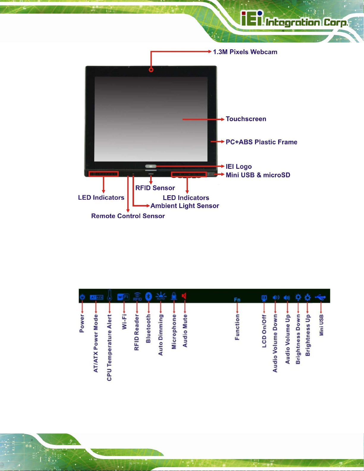
1.2.1 Front Panel
The front side of the AFL2-W15B-H61 is a flat bezel panel TFT LCD screen surrounded by
a PC/ABS plastic frame.
Page 4
Page 23
AFL2-W15B-H61
Figure 1-2: Front View
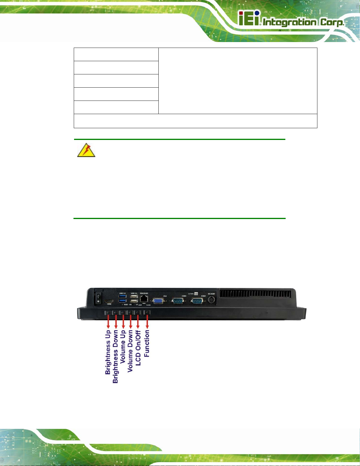
1.2.1.1 LED Indicators
There are several LED indicators located along the bottom of the LCD screen (Figure
1-3).
Figure 1-3: LED Indicators
The descriptions of each LED indicator are listed below.
Page 5
Page 24

LED Indicator Description
AFL2-W15B-H61
Power
AT/ATX Mode
CPU Temperature Alert
Wi-Fi
RFID
Bluetooth
Off: power cord not attached or power supply failure
Blinking amber: the system is connected to a power
source and is ready to be turned on.
Solid blue: the system is turned on.
Power on/off by the hot keys. See
AT: the system is in AT power mode
ATX: the system is in ATX power mode
Controlled by the AT/ATX power mode switch.
Blue: CPU temperature is normal.
Red: CPU temperature is at or over 80ºC.
On: the Wi-Fi module is enabled
Off: the Wi-Fi module is disabled.
Controlled by the BIOS. See Section
On: the optional RFID reader is enabled
Off: the optional RFID reader is disabled.
Controlled by the hot keys. See
On: the Bluetooth module is enabled
Off: the Bluetooth module is disabled.
Controlled by the BIOS. See Section
Table 1-3
4.5.2
Table 1-3
4.5.2
Page 6
Auto-Dimming
Microphone
Audio Mute
Mini USB
Function
On: the auto-dimming function is enabled
Off: the auto-dimming function is disabled.
Hold down Fn key for 3 seconds to enable/disable
auto-dimming function or control via BIOS setting (see
Section
On: the microphone is enabled
Off: the microphone is disabled.
Controlled by the BIOS. See Section
On (solid red): the audio is turned off
Off: the audio is turned on
Controlled by the hot keys. See
On: the Mini USB 2.0 module is enabled
Off: the Mini USB 2.0 module is disabled.
Controlled by the hot keys. See
Shows the status of the function keys below the LED
4.5.2).
4.5.2
Table 1-3
Table 1-3
Page 25
AFL2-W15B-H61
LCD On/Off
Audio Volume Down
Audio Volume Up
Brightness Down
Brightness Up
Table 1-2: LED Indicators
indicators. Blinks when the corresponding button is
pushed.
WARNING:
When the CPU temperature is at or over 80ºC, the CPU temperature
alert LED shows in red. If the alert LED turns red, the user must lower
the environments temperature or close some running applications to
cool down the CPU.
1.2.1.2 Function Keys
The function keys are located under the bottom right hand corner of the LCD screen
(
Figure 1-4).
Figure 1-4: Function Keys
Page 7
Page 26

The function keys are described in Table 1-3:
Key Combination Function Key Description
AFL2-W15B-H61
Fn
Fn + LCD On/Off
Fn + Audio Volume Down
Fn + Audio Volume Up
Fn + Brightness Down
Fn + Brightness Up
Fn: The function key can maintain for 2 seconds.
Table 1-3: Function Key Descriptions
Hold down Fn key for 3 seconds to enable/disable
auto-dimming function.
Enable/Disable RFID
Mute audio
Enable/Disable camera
Enable/Disable Mini USB or Micro SD
Power On/Off
Note: To power on the system, hold down the Fn +
Brightness Up buttons for six seconds. To power down the
system, hold down the Fn + Brightness Up buttons for six
seconds.
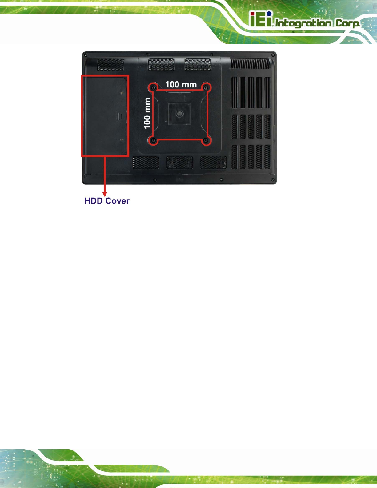
1.2.2 Rear Panel
The rear panel provides access to retention screw holes that support VESA mounting. The
Page 8
HDD bay and CF slot are protected by the HDD cover. Refer to
Figure 1-5.
Page 27
AFL2-W15B-H61
Figure 1-5: Rear View
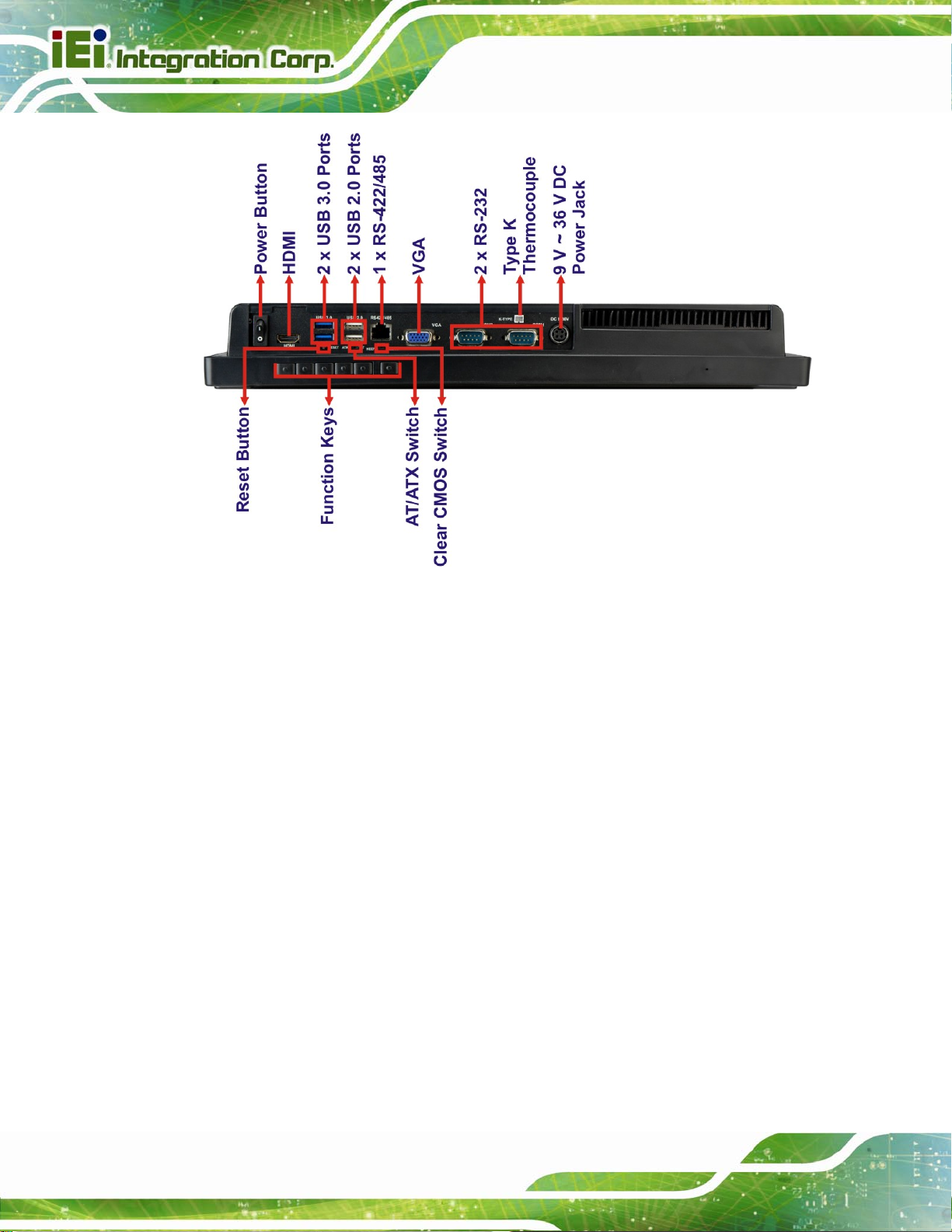
1.2.3 Bottom Panel
The bottom panel of the AFL2-W15B-H61 has the following connectors and switches
(
Figure 1-6):
1 x AT/ATX switch
1 x Clear CMOS switch
1 x 9V ~ 36V DC input power jack
6 x Function keys
1 x HDMI port
1 x Power button
1 x Reset button
2 x RS-232 DB-9 connectors
1 x RS-422/485 RJ-45 connector
1 x Type K thermocouple connector
2 x USB 2.0 connectors
2 x USB 3.0 connectors
1 x VGA port
Page 9
Page 28
AFL2-W15B-H61
Figure 1-6: Bottom Panel
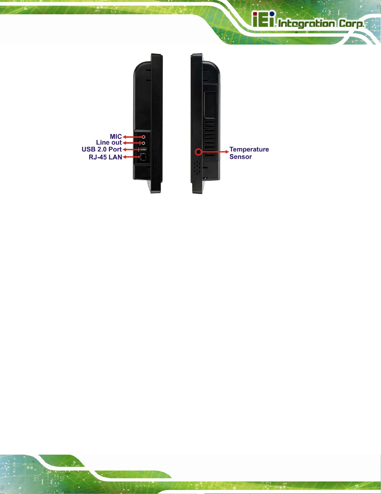
1.2.4 Side Panels
The side panels of the AFL2-W15B-H61 have the following features (Figure 1-7):
2 x Audio jacks (Line-out, Mic-in)
1 x RJ-45 LAN connector
1 x USB 2.0 connector
1 x Temperature sensor (left side panel)
Page 10
Page 29
AFL2-W15B-H61
Figure 1-7: Side Panels
1.3 Dimensions
The AFL2-W15B-H61 dimensions are shown below.
Width: 399.4 mm
Height: 271.2 mm
Depth: 58.8 mm
Page 11
Page 30
AFL2-W15B-H61
Figure 1-8: AFL2-W15B-H61 Dimensions (mm)
1.4 Internal Overview
The AFL2-W15B-H61 has the following components installed internally:
1 x Motherboard
2 x 2.0 GB 1333 MHz DDR3 SO-DIMMs
1 x 802.11 b/g/n wireless LAN module
Page 12
Page 31

AFL2-W15B-H61
1.5 System Specifications
The technical specifications for the AFL2-W15B-H61 systems are listed in Table 1-4.
Specification AFL2-W15B-H61
LCD Size 15.6" (16:9)
Max. Resolution 1366 (W) x 768 (H)
Brightness (cd/m2) 300
Contrast Ratio 500:1
LCD Color 16.7M
Pixel Pitch (H x V) (mm) 0.252 (H) x 0.252 (V)
Viewing Angle (H-V) 170° / 160°
Backlight MTBF (hr) 50,000
Touchscreen 5-Wire resistive type touch screen (R models only)
Projected capacitive type touch screen (PC models only)
CPU 2nd Generation Intel® Core™ i7/ i5/ i3, Pentium® or Celeron®
processor
Chipset Intel® H61
Ethernet Realtek RTL8111E PCIe GbE controller support ASF2.0
Memory Preinstalled two 204-pin 2 GB DDR3 SO-DIMM (max. 16G)
Expansion 1 x PCIe Mini slot for Wi-Fi module
1 x PCIe Mini slot reserved
SSD CF Type II socket
HDD 2.5" SATA 3Gb /s HDD bay
Audio Realtek ALC892 HD Audio codec (Line-out, Mic-in)
Speaker AMP 2 W + 2 W (built-in stereo speakers)
Camera 1.3 M pixels with low light function
Wireless 1 x Wireless LAN 802.11 b/g/n module (PCIe Mini card)
Bluetooth Optional internal USB interface, Bluetooth V2.0+EDR
RFID Reader EM 125 KHz or MIFARE 13.56 MHz card reader (optional)
MSR Card Reader MSR card reader (optional)
OSD Function LCD on/off, brightness up/down, volume up/down, Hot Key
Construction Material PC+ABS plastic front frame
Mounting VESA 100 mm x 100 mm (Panel, Wall, Rack, Stand or Arm)
Page 13
Page 32

Front Panel Color Black
Weight (N/G) 4.5 kg / 6.5 kg
Dimensions (W x H x D) (mm) 399.4 x 271.2 x 58.8
Operating Temperature -20ºC ~ 50ºC
Storage Temperature -20ºC ~ 60ºC
Humidity 10% ~ 95% (no-condensing)
IP level IP 64 compliant front panel
Power Supply 90W power adapter
Input: 100V AC ~ 240V AC @ 50 / 60 Hz
Output: 19V DC
Power Requirement 9V ~ 36V DC
Power Consumption 19V@3.42A (Intel® Core™ i3-2100T CPU with 4GB 1333 MHz
DDR3 memory)
I/O Ports and Switches 2 x RS-232 (DB-9 connector)
AFL2-W15B-H61
1 x GbE LAN (RJ-45 connector) on left side
1 x RS-422/485 (RJ-45 connector)
3 x USB 2.0 connectors (two on bottom side, one on left side)
2 x USB 3.0 connectors
1 x Mini USB 2.0 connector (on front panel)
1 x microSD card slot (on front panel)
2 x Audio jacks (line-out, MIC)
1 x VGA port (DB15 connector)
1 x HDMI port
1 x Power switch
1 x AT/ATX switch
1 x Reset button
1 x Clear CMOS button
1 x 9 V ~ 36 V DC input jack
Table 1-4: System Specifications
Page 14
Page 33

AFL2-W15B-H61
Chapter
2
2 Unpacking
Page 15
Page 34

2.1 Unpacking
To unpack the flat bezel panel PC, follow the steps below:
WARNING!
The front side LCD screen has a protective plastic cover stuck to the
screen. Only remove the plastic cover after the flat bezel panel PC has
been properly installed. This ensures the screen is protected during the
installation process.
Step 1: Use box cutters, a knife or a sharp pair of scissors that seals the top side of the
external (second) box.
AFL2-W15B-H61
Step 2: Open the external (second) box.
Step 3: Use box cutters, a knife or a sharp pair of scissors that seals the top side of the
internal (first) box.
Step 4: Lift the monitor out of the boxes.
Step 5: Remove both polystyrene ends, one from each side.
Step 6: Pull the plastic cover off the flat bezel panel PC.
Step 7: Make sure all the components listed in the pa cking list are present. Step 0:
2.1.1 Packing List
The AFL2-W15B-H61 flat bezel panel PC is shipped with the following components:
Quantity Item Image
Standard
Page 16
1 AFL2-W15B-H61 panel PC
Page 35

AFL2-W15B-H61
1 Power adapter
1 Power cord
(P/N: 63040-010090-020-RS)
(P/N: 32702-000401-100-RS)
1 Power transfer cord
(P/N: 32702-000300-100-RS)
1 RJ-45 to DB-9 COM Port Cable
(P/N: 32005-000200-200-RS)
1 OSD Remote Control
(P/N: 7Z000-SLPCB005-RS)
1 Temperature sensor cable
(P/N: 32133-004300-100-RS)
1 Pen for resistive touchscreen
(P/N: 43125-0002C0-00-RS)
4 M3 screw pack
(P/N: 44013-030041-RS)
4 M4 screw pack
(P/N: 44033-040061-RS)
1 Utility CD
1 One Key Recovery CD
(P/N: 7B000-000724-RS)
Page 17
Page 36

Optional
Wall mounting kit
(P/N: AFL WK-19/AFL WK-19B)
AFL2-W15B-H61
Panel Mounting Kit
(P/N: AFL2PK-W15B)
Rack Mounting Kit
(P/N: AFL2RK-W15B)
Arm
(P/N: ARM-1 1-RS/ARM-31-RS)
Stand
(P/N: STAND-A19/ STAND-B19/ STAND-C19/
STAND-210-R11)
Hybrid Card Reader
(P/N: AFL2P-12AMSI-U-R10)
Magnetic Stripe Reader
(P/N: AFL2P-12AMSR-U-R10)
Bluetooth Module Kit
(P/N: AFL2-BT-KIT01-R11)
Page 18
Page 37

AFL2-W15B-H61
OS: Win CE 6.0 (128MB CF Card)
(P/N: AFL2CF-15A-H61-CE060-128M-R10)
OS: Win XPE (2GB CF Card)
(P/N: AFL2CF-15A-H61-XPE-2G-R10)
OS: Win XPE (4GB CF Card)
(P/N: AFL2CF-15A-H61-XPE-4G-R10)
OS: Linux (2GB CF Card)
(P/N: AFL2CF-15A-H61-LNX-2G-R10)
OS: Win 7 Embedded (4GB CF Card)
(P/N: AFL2CF-15A-H61-WES7P-4G-R10
AFL2CF-15A-H61-WES7E-4G-R10)
If any of these items are missing or damaged, contact the distributor or sales
representative immediately.
Page 19
Page 38

AFL2-W15B-H61
3 Installation
Chapter
3
Page 20
Page 39

AFL2-W15B-H61
3.1 Anti-static Precautions
WARNING:
Failure to take ESD precautions during the maintenance of the
AFL2-W15B-H61 may result in permanent damage to the
AFL2-W15B-H61 and severe injury to the user.
Electrostatic discharge (ESD) can cause serious damage to electronic components,
including the AFL2-W15B-H61. Dry climates are especially susceptible to ESD. It is
therefore critical that whenever the AFL2-W15B-H61 is accessed internally, or any other
electrical component is handled, the following anti-static precautions are strictly adhered
to.
Wear an anti-static wristband: - Wearing a simple anti-static wristband can
help to prevent ESD from damaging the board.
Self-grounding: - Before handling the board touch any grounded conducting
material. During the time the board is handled, frequently touch any
conducting materials that are connected to the ground.
Use an anti-static pad: - When configuring the AFL2-W15B-H61, place it on
an antic-static pad. This reduces the possibility of ESD damaging the
AFL2-W15B-H61.
Only handle the edges of the PCB: - When handling the PCB, hold the PCB
by the edges.
3.2 Installation Precautions
When installing the flat bezel panel PC, please follow the precautions listed below:
Power turned off: When installing the flat bezel panel PC, make sure the
power is off. Failing to turn off the power may cause severe injury to the body
and/or damage to the system.
Certified Engineers: Only certified engineers should install and modify
onboard functionalities.
Page 21
Page 40

Anti-static Discharge : If a user open the rear p anel of the flat bezel panel PC,
to configure the jumpers or plug in added peripheral devices, ground
themselves first and wear and anti-static wristband.
3.3 Installation and Configuration Steps
The following installation steps must be followed.
Step 1: Unpack the flat bezel panel PC.
Step 2: Install the HDD.
Step 3: Install the CF card.
Step 4: Install the RFID reader. (optional)
Step 5: Configure the system.
AFL2-W15B-H61
Step 6: Connect peripheral devices to the flat bezel panel PC.
Step 7: Mount the flat bezel panel PC. Step 0:
3.4 HDD Installation
WARNING:
Over-tightening back cover screws will crack the plastic frame.
Maximum torque for cover screws is 5 kg-cm (0.36 lb-ft/0.49 Nm).
To install the HDD into the AFL2-W15B-H61, please follow the steps below:
Step 1: Remove two (2) retention screws from the HDD cover (
Figure 3-1).
Page 22
Page 41

AFL2-W15B-H61
Figure 3-1: HDD Cover Retention Screws
Step 2: Remove the HDD cover from the device.
Step 3: Loosen the captive screw to release the HDD bracket from the chassis. Slide the
HDD bracket out of the device as shown (
Figure 3-2: HDD Bracket Removal
Figure 3-2).
Step 4: Insert an HDD into the bracket as shown (
Figure 3-3).
Page 23
Page 42

AFL2-W15B-H61
Figure 3-3: Inserting the HDD
Step 5: Secure the HDD to the bracket using four (4) retention screws (two screws on
each side) (
Figure 3-4: Securing the HDD
Step 6: Slide the HDD module back into the device.
Figure 3-4).
Page 24
Step 7: Tighten the captive screw.
Step 8: Replace the HDD cover and secure it using two (2) retention screws. Step 0:
Page 43

AFL2-W15B-H61
3.5 CF Card Installation
The AFL2-W15B-H61 has one CF Type II slot under the HDD bay. To install the CF card,
follow the instructions below.
Step 1: Remove two (2) retention screws from the HDD cover (
Step 2: Remove the HDD cover from the device.
Step 3: Locate the CF slot (
Figure 3-5: CF Card Location
Step 4: Insert a CF card into the slot (
Figure 3-5).
Figure 3-6).
Figure 3-1).
Figure 3-6: Insert CF Card
Step 5: Replace the HDD cover and secure it using two (2) retention screws. Step 0:
Page 25
Page 44

3.6 RFID Reader Installation (Optional)
An optional RFID reader can be installed in the AFL2-W15B-H61. To install the RFID
reader, follow the instructions below.
AFL2-W15B-H61
Step 1: Remove a total of ten (10) retention screws from the back cover (
Figure 3-7).
Figure 3-7: Back Cover Retention Screws
Step 2: Remove the seven (7) retention screws securing the internal aluminum cover to
Page 26
the chassis (
Figure 3-8: Internal Cover Retention Screws
Figure 3-8).
Page 45

AFL2-W15B-H61
Step 3: Install the RFID reader module in the location shown in Figure 3-9 by two
retention screws.
Figure 3-9: RFID Reader Module Installation
Step 4: Connect the RFID module to the RFID connector on the main board (
3-10). The RFID connector pinouts are listed in Section
Step 5: Place the RFID antenna on the location shown in
RFID antenna to the RFID antenna connector on the RFID module.
8.2.17.
Figure 3-10. Connect the
Figure
Figure 3-10: RFID Reader Connection
Page 27
Page 46

Step 6: Replace the internal cover and back cover using previously removed retention
screws. Step 0:
3.7 AT/ATX Mode Selection
AT or ATX power mode can be used on the AFL2-W15B-H61. The selection is made
through an AT/ATX switch located on the bottom panel. To select AT mode or ATX mode,
follow the steps below.
AFL2-W15B-H61
Step 1: Locate the AT/ATX switch on the bottom panel (
Figure 3-11: AT/ATX Switch Location
Step 2: Adjust the AT/ATX switch. Step 0:
Figure 3-11).
3.7.1 AT Power Mode
With the AT mode selected, the power is controlled by a central power unit rather than a
power switch. The AFL2-W15B-H61 panel PC turns on automatically when the power is
connected. The AT mode benefits a production line to control multiple panel PCs from a
central management center and other applications including:
ATM
Self-service kiosk
Plant environment monitoring system
Factory automation platform
Manufacturing shop flow
3.7.2 ATX Power Mode
With the ATX mode selected, the AFL2-W15B-H61 panel PC goes in a standby mode
when it is turned off. The panel PC can be easily turned on via network or a power switch
in standby mode. Remote power control is perfect for advertising applications since the
Page 28
Page 47
AFL2-W15B-H61
broadcasting time for each panel PC can be set individually and cont rolled remotely . Other
possible application includes
Security surveillance
Point-of-Sale (POS)
Advertising terminal
3.8 Clear CMOS
If the AFL2-W15B-H61 fails to boot due to improper BIOS settings, the clear CMOS switch
clears the CMOS data and resets the system BIOS information. To do this, adjust the
clear CMOS switch to clear CMOS mode for a few seconds then adjust the clear CMOS
switch back to keep CMOS mode.
Step 1: Locate the clear CMOS switch on the bottom panel (
Figure 3-12: Clear CMOS Switch Location
Step 2: Adjust the clear CMOS switch. Step 0:
3.9 Reset the System
The reset button enables user to reboot the system when the system is turned on. To
reboot the system, follow the steps below.
Step 1: Locate the reset button on the bottom panel (
Figure 3-12).
Figure 3-13).
Figure 3-13: Reset Button Location
Page 29
Page 48

Step 2: Press the reset button. Step 0:
3.10 Powering On the System
To power on the system, follow the steps below:
AFL2-W15B-H61
Step 1: Locate the Function and Brightness Up function keys. See Section
Step 2: Hold down the Function and Brightness Up buttons for six seconds to power on
the system. Step 0:
3.11 Powering Off the System
To power off the system, follow the steps below:
Step 1: Locate the Function and Brightness Up function keys. See Section
Step 2: Hold down the Function and Brightness Up buttons for six seconds to power off
the system. Step 0:
3.12 Mounting the System
WARNING:
1.2.1.2.
1.2.1.2.
Page 30
When mounting the flat bezel panel PC onto an arm, onto the wall or
onto a panel, it is better to have more than one person to help with the
installation to make sure the panel PC does not fall down and get
damaged.
The five methods of mounting the AFL2-W15B-H61 are listed below.
Wall mounting
Panel mounting
Rack mounting
Arm mounting
Stand mounting
Page 49

AFL2-W15B-H61
The five mounting methods are described below.
3.12.1 Wall Mounting
To mount the flat bezel panel PC onto the wall, please follow the steps below.
Step 1: Select the location on the wall for the wall-mounting bracket.
Step 2: Carefully mark the locations of the four screw holes in the bracket on the wall.
Step 3: Drill four pilot holes at the marked locations on the wall for the bracket retention
screws.
Step 4: Align the wall-mounting bracket screw holes with the pilot holes.
Step 5: Secure the mounting-bracket to the wall by inserting the retention screws into
the four pilot holes and tightening them (
Figure 3-14).
Figure 3-14: Wall-mounting Bracket
Page 31
Page 50

Step 6: Insert the four monitor mounting screws provided in the wall mount kit into the
four screw holes on the real panel of the flat bezel panel PC and tighten until the
AFL2-W15B-H61
screw shank is secured against the rear panel (
Figure 3-15).
WARNING:
Please use the M4 screws provided in the wall mount kit for the rear panel.
If the screw is missing, the thread depth of the replacement screw should
be not more than 4 mm.
Step 7: Align the mounting screws on the monitor rear panel with the mounting holes on
the bracket.
Step 8: Carefully insert the screws through the holes and gently pull the monitor
downwards until the monitor rests securely in the slotted holes (
Ensure that all four of the mounting screws fit snugly into their respective slotted
holes.
Figure 3-15).
NOTE:
In the diagram below the bracket is already installed on the wall.
Page 32
Page 51

AFL2-W15B-H61
Figure 3-15: Chassis Support Screws
Step 9: Secure the panel PC by fastening the retention screw of the wall-mounting
bracket. (
Figure 3-16).
Figure 3-16: Secure the Panel PC
Page 33
Page 52

3.12.2 Panel Mounting
To mount the AFL2-W15B-H61 flat bezel panel PC into a panel, please follow the steps
below.
Step 1: Select the position on the panel to mount the flat bezel panel PC.
Step 2: Cut out a section corresponding to the size shown below. The size must be
smaller then the outer edge.
AFL2-W15B-H61
Figure 3-17: Cutout Dimensions
Step 3: Slide the flat bezel panel PC through the hole until the frame is flush against the
panel.
Step 4: Align the panel mounting bracket screw holes with the VESA mounting holes on
the rear of the panel PC.
Step 5: Secure the two panel mounting brackets to the rear of the panel PC by insertin g
the four retention screws into the VESA mounting holes (
Step 6: Insert the panel mounting clamps into the holes of the panel mounting brackets
Figure 3-18 o). There are a total of 4 panel mounting clamps for
(
AFL2-W15B-H61.
Figure 3-18 n).
Page 34
Page 53

AFL2-W15B-H61
Step 7: Tighten the screws that pass through the p anel mou nting clamp s u ntil the plastic
caps at the front of all the screws are firmly secured to the panel.
Step 8: Install the covers into the panel mounting bracket. Each mounting bracket
includes two side covers and one top cover (
Figure 3-18 p).
Figure 3-18: Tighten the Panel Mounting Clamp Screws
3.12.3 Cabinet and Rack Installation
The AFL2-W15B-H61 flat bezel panel PC can be installed into a cabinet or rack. The
installation procedures are similar to the panel mounting installation. To do this, please
follow the steps below:
Page 35
Page 54

AFL2-W15B-H61
NOTE:
When purchasing the cabinet/rack installation bracket, make sure it is
compatible with both the AFL2-W15B-H61 flat bezel panel PC and the
rack/cabinet into which the AFL2-W15B-H61 is installed.
Step 9: Slide the rear chassis of the AFL2-W15B-H61 flat bezel panel PC through the
rack/cabinet bracket until the aluminum frame is flush against the front of the
bracket (
Figure 3-19).
Figure 3-19: The Rack/Cabinet Bracket
Step 1: Align the panel mounting bracket screw holes with the VESA mounting holes on
the rear of the panel PC.
Step 2: Secure the two rack mounting brackets to the rear of the panel PC by inserting
Page 36
the four retention screws into the VESA mounting holes (
Step 3: Insert the rack mounting clamps into the holes of the rack mounting brackets
Figure 3-20 o). There are a total of 4 rack mounting clamps for
(
AFL2-W15B-H61.
Step 4: Tighten the screws that pass through the rack mounting clamps until the plastic
caps at the front of all the screws are firmly secured to the panel.
Figure 3-20 n).
Page 55

AFL2-W15B-H61
Step 5: Install the covers into the rack mounting bracket. Each mounting bracket
includes two side covers and one top cover (
Figure 3-20 p).
Figure 3-20: Secure the Rack/Cabinet Bracket
Step 6: Slide the flat bezel panel PC with the attached rack/cabinet bracket into a rack or
cabinet (
Figure 3-21).
Figure 3-21: Install into a Rack/Cabinet
Page 37
Page 56

Step 7: Once the flat bezel panel PC with the attached rack/cabinet bracket has been
properly inserted into the rack or cabinet, secure the front of the rack/cabinet
AFL2-W15B-H61
bracket to the front of the rack or cabinet (
Figure 3-21).
3.12.4 Arm Mounting
The AFL2-W15B-H61 is VESA (Video Electronics Standards Association) compliant and
can be mounted on an arm with a 100mm interface pad. To mount the AFL2-W15B-H61
on an arm, please follow the steps below.
Step 1: The arm is a separately purchased item. Please correctly mount the arm onto
the surface it uses as a base. To do this, refer to the installation documentation
that came with the mounting arm.
NOTE:
When purchasing the arm please ensure that it is VESA compliant and that
the arm has a 100 mm interface pad. If the mounting arm is not VESA
compliant it cannot be used to support the AFL2-W15B-H61 flat bezel
panel PC.
Step 2: Once the mounting arm has been firmly attached to the surface, lift the flat bezel
panel PC onto the interface pad of the mounting arm.
Step 3: Align the retention screw holes on the mounting arm interface with those in the
flat bezel panel PC (
Figure 3-22).
Page 38
Page 57

AFL2-W15B-H61
Figure 3-22: Arm Mounting Retention Screw Holes
Step 4: Secure the A FL2-W15B-H61 to the interface pad by inserting four retention
screws through the mounting arm interface pad and into the AFL2-W15B-H61.
Step 0:
Figure 3-23: Arm Mounting (ARM-11-RS)
Page 39
Page 58

3.12.5 Stand Mounting
To mount the AFL2-W15B-H61 using the stand mounting kit, please follow the steps
below.
Step 1: Locate the screw holes on the rear of the AFL2-W15B-H61. This is where the
bracket will be attached.
Step 2: Align the bracket with the screw holes.
Step 3: To secure the bracket to the AFL2-W15B-H61 insert the retention screws into
the screw holes and tighten them.Step 0:
AFL2-W15B-H61
Figure 3-24: Stand Mounting (Stand-A/Bxx)
3.13 External Peripheral Device Connection
The following external peripheral devices can be connected to the external peripheral
interface connectors.
Audio devices
Page 40
Page 59

AFL2-W15B-H61
HDMI devices
RJ-45 Ethernet cable connector
Serial port devices
USB devices
VGA monitor
To install these devices, connect the corresponding cable connector from the actual
device to the corresponding AFL2-W15B-H61 external peripheral interface connector
making sure the pins are properly aligned.
3.13.1 Audio Connection
The audio jacks on the external audio connector enable the AFL2-W15B-H61 to be
connected to a stereo sound setup. To install the audio devices, follow the steps below.
Step 1: Identify the audio plugs. The plugs on your home theater system or speakers
may not match the colors on the rear panel. If audio plugs are plugged into the
wrong jacks, sound quality will be very bad.
Step 2: Plug the audio plugs into the audio jacks. Plug the audio plugs into the audio
jacks. If the plugs on your speakers are different, an adapter will need to be used
to plug them into the audio jacks.
Line Out port (Lime): Connects to a head phone or a speaker.
Microphone (Pink): Connects to a microphone.
Page 41
Page 60

Figure 3-25: Audio Connector
Step 3: Check audio clarity. Check that the sound is coming through the right speakers
AFL2-W15B-H61
by adjusting the balance front to rear and left to right.
3.13.2 HDMI Device Connection
The HDMI connector transmits a digital signal to compatible HDMI display devices such
as a TV or computer screen. To connect the HDMI cable to the AFL2-W15B-H61, follow
the steps below.
Step 1: Locate the HDMI connector. The location is shown in Chapter 1.
Step 2: Align the connector. Alig n the HDMI connector with the HDMI port. Make sure
the orientation of the connector is correct.
Page 42
Page 61

AFL2-W15B-H61
Figure 3-26: HDMI Connection
Step 3: Insert the HDMI connector. Gently insert the HDMI connector. The connector
should engage with a gentle push. If the connector does not insert easily, check
again that the connector is aligned correctly, and that the connector is being
inserted with the right way up.
3.13.3 LAN Connection
There is one external RJ-45 LAN connectors The RJ-45 connector enables connection to
an external network. To connect a LAN cable with an RJ-45 connector, please follow the
instructions below.
Step 1: Locate the RJ-45 connectors. The location of the LAN conne ctor is shown in
Chapter 1.
Step 2: Align the connectors. Align the RJ-45 connector on the LAN cable with one of
the RJ-45 connectors on the AFL2-W15B-H61. See
Figure 3-27.
Page 43
Page 62

AFL2-W15B-H61
Figure 3-27: LAN Connection
Step 3: Insert the LAN cable RJ-45 connector. Once aligned, gently insert the LAN
cable RJ-45 connector into the external interface.
3.13.4 Serial Device Connection
There are two external RS-232 DB-9 connectors and one RS-422/485 RJ-45 connector for
serial device connection. Follow the steps below to connect a serial device to the
AFL2-W15B-H61.
3.13.4.1 DB-9 Serial Port Connection
Follow the steps below to connect a serial device to the DB-9 connector of the
AFL2-W15B-H61 panel PC.
Step 1: Locate the DB-9 connector. The locations of the DB-9 connectors are shown
in Chapter 1.
Page 44
Step 2: Insert the serial connector. Insert the DB-9 connector of a serial device into
the DB-9 connector on the bottom panel. See
Figure 3-28.
Page 63

AFL2-W15B-H61
Figure 3-28: DB-9 Serial Port Connector
Step 3: Secure the connector. Secure the serial device connector to the external
interface by tightening the two retention screws on either side of the connector.
3.13.4.2 RJ-45 Serial Port Connection
Follow the steps below to connect a serial device to the RJ-45 serial port connector of the
AFL2-W15B-H61 panel PC.
Step 1: Locate the RJ-45 serial port. The location of the RJ-45 serial port is shown in
Chapter 1.
Step 2: Connect the RJ-45 to COM port cable to the panel PC. Insert the RJ-45
connector end of cable into the RJ-45 serial port. See
Step 3: Connect the serial device. Connect a serial device to the DB-9 connector end
Figure 3-29.
of the cable. See
Figure 3-29.
Page 45
Page 64

AFL2-W15B-H61
Figure 3-29: RJ-45 Serial Port Connector
Step 4: Secure the connector. Secure the serial device connector to the external
interface by tightening the two retention screws on either side of the connector.
3.13.5 Type K Temperature Sensor Connection
The AFL2-W15B-H61 has a type K thermocouple connector on the bottom panel. The
type K connector is connected to a type K temperature sensor cable, which can be found
in the packing list. To connect a type K temperature sensor cable to the AFL2-W15B-H61,
please follow the steps below.
Step 1: Locate the type K connector on the bottom panel. See
Step 2: Align the connectors. Align the type K connector on the type K temperature
sensor cable with the type K connector on the AFL2-W15B-H61.
Step 3: Insert the temperature sensor cable type K connector. Once aligned, gently
insert the temperature sensor cable type K connector into the external interface.
Figure 3-30.
Step 0:
Page 46
Figure 3-30: Type K Temperature Sensor Installation
Page 65

AFL2-W15B-H61
3.13.6 USB Device Connection
NOTE:
User must install the USB 3.0 driver before connecting a USB device to
the system or else the system may not recognize the connected
device.
There are three USB 2.0 connectors and two USB 3.0 connectors on the AFL2-W15B-H61.
To connect a USB device, please follow the instructions below.
Step 1: Locate the USB connectors. The locations of the USB connectors are shown
in Chapter 1.
Step 2: Align the connectors. Align the USB device connector with one of the
connectors on the AFL2-W15B-H61. Se e
Figure 3-31.
Figure 3-31: USB Device Connection
Page 47
Page 66

Step 3: Insert the device connector. Once aligned, gently insert the USB device
connector into the onboard connector. Step 0:
3.13.7 VGA Monitor Connection
The AFL2-W15B-H61 has a single female DB-15 connector on the external peripheral
interface panel. The DB-15 connector is connected to a CRT or VGA monitor. To connect
a monitor to the AFL2-W15B-H61, please follow the instructions below.
Step 1: Locate the female DB-15 connector. The location of the female DB-15
connector is shown in Chapter 1.
Step 2: Align the VGA connector. Align the male DB-15 connector on the VGA screen
cable with the female DB-15 connector on the external peripheral interface.
AFL2-W15B-H61
Step 3: Insert the VGA connector. Once the conne ctors are prop erly aligned with the
insert the male connector from the VGA screen into the female connector on the
AFL2-W15B-H61. See
Figure 3-32: VGA Connector
Step 4: Secure the connector. Secure the DB-15 VGA connector from the VGA
Figure 3-32.
Page 48
monitor to the external interface by tightening the two retention screws on either
side of the connector.
Page 67

AFL2-W15B-H61
Chapter
4
4 BIOS Setup
Page 49
Page 68

4.1 Introduction
A licensed copy of the BIOS is preprogrammed into the ROM BIOS. The BIOS setup
program allows users to modify the basic system configuration. This chapter describes
how to access the BIOS setup program and the configuration options that may be
changed.
4.1.1 Starting Setup
The UEFI BIOS is activated when the computer is turned on. The setup program can be
activated in one of two ways.
AFL2-W15B-H61
1. Press the DEL or F2 key as soon as the system is turned on or
2. Press the DEL or F2 key when the “Press DEL or F2 to enter
SETUP” message appears on the screen. 0.
If the message disappears before the DEL or F2 key is pressed, restart the computer and
try again.
4.1.2 Using Setup
Use the arrow keys to highlight items, press ENTER to select, use the PageUp and
PageDown keys to change entries, press F1 for help and press E
keys are shown in the following table.
Key Function
Up arrow Move to the item above
Down arrow Move to the item below
Left arrow Move to the item on the left hand side
Right arrow Move to the item on the right hand side
+ Increase the numeric value or make changes
- Decrease the numeric value or make changes
SC to quit. Navigation
Page 50
F1 key General help, only for St atus Page Setup Menu and Option
Page Setup Menu
Page 69

AFL2-W15B-H61
F2 key Load previous values.
F3 key Load optimized defaults
F4 key Save changes and Exit BIOS
Esc key Main Menu – Quit and do n ot save ch anges into CMOS
Table 6-1: BIOS Navigation Keys
4.1.3 Getting Help
When F1 is pressed a small help window describing the appropriate keys to use and the
Status Page Setup Menu and Option Page Setup Menu -Exit current page and return to Main Menu
possible selections for the highlighted item appears. To exit the Help Window press E
the F1 key again.
4.1.4 Unable to Reboot after Configuration Changes
If the computer cannot boot after changes to the system configuration are made, CMOS
defaults.
4.1.5 BIOS Menu Bar
The menu bar on top of the BIOS screen has the following main items:
Main – Changes the basic system configuration.
Advanced – Changes the advanced system settings.
Chipset – Changes the chipset settings.
Boot – Changes the system boot configuration.
Security – Sets User and Supervisor Passwords.
Save & Exit – Selects exit options and loads default settings
SC or
The following sections completely describe the configuration options found in the menu
items at the top of the BIOS screen and listed above.
Page 51
Page 70

AFL2-W15B-H61
4.2 Main
The Main BIOS menu (9BIOS Menu 1) appears when the BIOS Setup program is entered.
The Main menu gives an overview of the basic system information.
Aptio Setup Utility – Copyright (C) 2011 American Megatrends, Inc.
Main Advanced Chipset Boot Security Save & Exit
BIOS Information
BIOS Vendor American Megatrends
Core Version 4.6.4.0 0.03
Compliency UEFI 2.0
Project Version SE17AR16.ROM
Build Date and Time 08/23/2012 17:34:22
iWDD Vendor ICP
iWDD Version SE17ER17.bin
Memory Information
Total Memory 2048 MB (DDR3 1333)
System Date [Fri 09/05/2012]
System Time [17:16:27]
Access Level Administrator
Version 2.11.1210. Copyright (C) 2011 American Megatrends, Inc.
Set the Date. Use Tab to
switch between Data
elements.
----------------------
ÅÆ
: Select Screen
↑ ↓: Select Item
Enter Select
+/-: Change Opt.
F1: General Help
F2: Previous Values
F3: Optimized Defaults
F4: Save & Exit
ESC: Exit
BIOS Menu 1: Main
Î BIOS Information
The BIOS Information lists a brief summary of the BIOS. The fields in BIOS Information
cannot be changed. The items shown in the system overview include:
BIOS Vendor: Installed BIOS vendor
Core Version: Current BIOS version
Compliency: Current compliant version
Project Version: the bo ard version
Build Date and Time: Date the current BIOS version was made
Î iWDD Vendor
The iWDD Vendor displays the installed iWDD vendor. The fields in iWDD
Vendor cannot be changed.
Page 52
Page 71

AFL2-W15B-H61
Î iWDD Version
The iWDD Version displays the current iWDD version. The fields in iWDD
Version cannot be changed.
Î Memory Information
The Memory Information lists a brief summary of the on-board memory. The fields in
Memory Information cannot be changed.
Total Memory: Displays the auto-detected system memory size and type.
The System Overview field also has two user configurable fields:
Î System Date [xx/xx/xx]
Use the System Date option to set the system date. Manually enter the day, month and
year.
Î System Time [xx:xx:xx]
Use the System Time option to set the system time. Manually enter the hours, minutes
and seconds.
4.3 Advanced
Use the Advanced menu (9BIOS Menu 2) to configure the CPU and peripheral devices
through the following sub-menus:
WARNING:
Setting the wrong values in the sections below may cause the system
to malfunction. Make sure that the settings made are compatible with
the hardware.
ACPI Settings
RTC Wake Settings
Trusted Computing
Page 53
Page 72
CPU Configuration
SATA Configuration
Intel TXT (LT) Configuration
USB Configuration
F81216 Super IO Configuration
H/W Monitor
Serial Port Console Redirection
iEi Feature
Aptio Setup Utility – Copyright (C) 2011 American Megatrends, Inc.
Main Advanced Chipset Boot Security Save & Exit
> ACPI Settings
> RTC Wake Settings
> Trusted Computing
> CPU Configuration
> SATA Configuration
> Intel TXT(LT) Configuration
> USB Configuration
> F81216 Super IO Configuration
> H/M Monitor
> Serial Port Console Redirection
> iEi Feature
Version 2.11.1210. Copyright (C) 2011 American Megatrends, Inc.
System ACPI Parameters.
----------------------
ÅÆ
↑ ↓: Select Item
Enter Select
+/-: Change Opt.
F1: General Help
F2: Previous Values
F3: Optimized Defaults
F4: Save & Exit
ESC: Exit
AFL2-W15B-H61
: Select Screen
BIOS Menu 2: Advanced
4.3.1 ACPI Settings
The ACPI Settings menu (9BIOS Menu 3) configures the Advanced Configuration and
Power Interface (ACPI) options.
Page 54
Page 73

S
AFL2-W15B-H61
Aptio Setup Utility – Copyright (C) 2011 American Megatrends, Inc.
Advanced
ACPI Settings
ACPI Sleep State [S1 (CPU Stop Clock)]
Version 2.11.1210. Copyright (C) 2011 American Megatrends, Inc.
BIOS Menu 3: ACPI Configuration
elect the highest ACPI
sleep state the system
will enter, when the
SUSPEND button is
pressed.
----------------------
ÅÆ
: Select Screen
↑ ↓: Select Item
Enter Select
+/-: Change Opt.
F1: General Help
F2: Previous Values
F3: Optimized Defaults
F4: Save & Exit
ESC: Exit
Î ACPI Sleep State [S1 (CPU Stop Clock)]
Use the ACPI Sleep State option to specify the sleep state the system enters when it is
not being used.
Î
S1 (CPU Stop
Clock)
Î
S3 (Suspend to
RAM)
DEFAULT
The system enters S1 (POS) sleep state. The
system appears off. The CPU is stopped; RAM is
refreshed; the system is running in a low power
mode.
The caches are flushed and the CPU is powered
off. Power to the RAM is maintained. The
computer returns slower to a working state, but
more power is saved.
4.3.2 RTC Wake Settings
The RTC Wake Settings menu (BIOS Menu 4) configures RTC wake event.
Page 55
Page 74

E
w
Aptio Setup Utility – Copyright (C) 2011 American Megatrends, Inc.
Advanced
Wake system with Fixed Time [Disabled]
Version 2.14.1219. Copyright (C) 2011 American Megatrends, Inc.
AFL2-W15B-H61
nable or disable System
ake on alarm event. When
enabled, System will
wake on the
dat::hr::min::sec
specified
----------------------
ÅÆ
: Select Screen
↑ ↓: Select Item
Enter Select
F1 General Help
F2 Previous Values
F3 Optimized Defaults
F4 Save
ESC Exit
BIOS Menu 4: RTC Wake Settings
Î Wake System with Fixed Time [Disabled]
Use the Wake System with Fixed Time option to specify the time the system should be
roused from a suspended state.
Î
Disabled DEFAULT
Î
Enabled
The real time clock (RTC) cannot generate a wake
event
If selected, the following appears with values that
can be selected:
*Wake up every day
*Wake up date
*Wake up hour
*Wake up minute
*Wake up second
After setting the alarm, the computer turns itself on
from a suspend state when the alarm goes off.
Page 56
Page 75

E
AFL2-W15B-H61
4.3.3 Trusted Computing
Use the Trusted Computing menu (BIOS Menu 5) to configure settings related to the
Trusted Computing Group (TCG) Trusted Platform Module (TPM).
Aptio Setup Utility – Copyright (C) 2011 American Megatrends, Inc.
Advanced
TPM Configuration
TPM SUPPORT [Disable]
Current TPM Status Information
NO TPM Hardware
Version 2.11.1210. Copyright (C) 2011 American Megatrends, Inc.
nables or Disables TPM
support. O.S. will not
show TPM. Reset of
platform is required.
----------------------
ÅÆ
: Select Screen
↑ ↓: Select Item
Enter Select
+/=” Change Opt.
F1 General Help
F2 Previous Values
F3 Optimized Defaults
F4 Save & Exit
ESC Exit
BIOS Menu 5: TPM Configuration
Î TPM Support [Disable]
Use the TPM Support option to configure support for the TPM.
Î
Disable DEFAULT
Î
Enable
TPM support is disabled.
TPM support is enabled.
4.3.4 CPU Configuration
Use the CPU Configuration menu (BIOS Menu 6) to enter the CPU Information
submenu or enable Intel Virtualization Technology.
Page 57
Page 76

Aptio Setup Utility – Copyright (C) 2011 American Megatrends, Inc.
Advanced
CPU Configuration
> CPU Information
Hyper-threading [Enabled]
Intel Virtualization Technology [Disabled]
Version 2.11.1210. Copyright (C) 2011 American Megatrends, Inc.
BIOS Menu 6: CPU Configuration
AFL2-W15B-H61
Socket specific CPU
Information
----------------------
ÅÆ
: Select Screen
↑ ↓: Select Item
Enter Select
+/-: Change Opt.
F1: General Help
F2: Previous Values
F3: Optimized Defaults
F4: Save & Exit
ESC: Exit
Î Hyper-threading [Enabled]
Use the Hyper-threading function to enable or disable the CPU hyper threading function.
Î
Disabled
Î
Enabled DEFAULT
Î Intel Virtualization Technology [Disabled]
Use the Intel Virtualization Technology option to enable or disable virtualization on the
system. When combined with third party software, Intel Virtualization technology allows
several OSs to run on the same system at the same time.
Î
Disabled DEFAULT
Î
Enabled
Disables the use of hyper-threading technology
Enables the use of hyper-threading technology
Disables Intel Virtualization Technology.
Enables Intel Virtualization Technology.
4.3.4.1 CPU Information
Page 58
Use the CPU Information submenu (BIOS Menu 7) to view detailed CPU specifications
and configure the CPU.
Page 77

AFL2-W15B-H61
Aptio Setup Utility – Copyright (C) 2011 American Megatrends, Inc.
Advanced
Socket 0 CPU Information
Intel(R) Core(TM) i3-2100T CPU @ 2.50GHz
CPU Signature 206a7
Microcode Patch 25
Max CPU Speed 2500 MHz
Min CPU Speed 1600 MHz
Processor Cores 2
Intel HT Technology Supported
Intel VT-x Technology Supported
Intel SMX Technology Not Supported
L1 Data Cache 32 kB x 2
L1 Code Cache 32 kB x 2
L2 Cache 256 kB x 2
L3 Cache 3072 kB
Version 2.11.1210. Copyright (C) 2011 American Megatrends, Inc.
BIOS Menu 7: CPU Configuration
----------------------
ÅÆ
: Select Screen
↑ ↓: Select Item
Enter Select
+/-: Change Opt.
F1: General Help
F2: Previous Values
F3: Optimized Defaults
F4: Save & Exit
ESC: Exit
The CPU Configuration menu (
Processor Type: Lists the brand name of the CPU being used
CPU Signature: Lists the CPU signature value.
Microcode Patch: Lists the microcode patch being used.
Max CPU Speed: Lists the maximum CPU processing speed.
Min CPU Speed: Lists the minimum CPU processing speed.
Processor Cores: Lists the number of the processor core
Intel HT Technology: Indicates if Intel HT Technology is supported by the
CPU.
Intel VT-x Technology: Indicates if Intel VT-x Technology is supported by the
CPU.
Intel SMX Technology: Indicates if Intel SMX Technology is supported by the
CPU.
L1 Data Cache: Lists the amount of data storage space on the L1 cache.
L1 Code Cache: Lists the amount of code storage space on the L1 cache.
L2 Cache: Lists the amount of storage space on the L2 cache.
BIOS Menu 6) lists the following CPU details:
L3 Cache: Lists the amount of storage space on the L3 cache.
Page 59
Page 78

AFL2-W15B-H61
4.3.5 SATA Configuration
Use the SATA Configuration menu (BIOS Menu 8) to change and/or set the
configuration of the SATA devices installed in the system.
Aptio Setup Utility – Copyright (C) 2011 American Megatrends, Inc.
Advanced
SATA Configuration
SATA Mode [IDE Mode]
Serial-ATA Controller 0 [Compatible]
Serial-ATA Controller 1 [Enhanced]
SATA Port0 Not Present
SATA Port1 Not Present
(1) IDE Mode. (2) AHCI
Mode. (3) RAID Mode.
---------------------
ÅÆ
: Select Screen
↑ ↓: Select Item
Enter Select
+/-: Change Opt.
F1 General Help
F2 Previous Values
F3 Optimized Defaults
F4 Save & Exit
ESC Exit
Version 2.11.1210. Copyright (C) 2011 American Megatrends, Inc.
BIOS Menu 8: IDE Configuration
Î SATA Mode [IDE Mode]
Use the SATA Mode option to configure SATA devices as normal IDE devices.
Î
Disable
Î
IDE Mode DEFAULT
Î Serial-ATA Controller 0 [Compatible]
Use the Serial-ATA Controller 0 option to configure the Serial-ATA controller mode when
the SATA mode is set to IDE Mode.
Î
Disabled
Î
Enhanced
Disables SATA devices.
Configures SATA devices as normal IDE device.
Disables Serial-ATA controller.
Configures the Serial-ATA controller to be in enhanced
Page 60
mode. In this mode, IDE channels and SATA channels
are separated. Some legacy OS do not support this
mode.
Page 79

AFL2-W15B-H61
Î
Compatible DEFAULT
Î Serial-ATA Controller 1 [Enhanced]
Use the Serial-ATA Controller 1 option to configure the Serial-ATA controller mode when
the SATA mode is set to IDE Mode.
Î
Disabled
Î
Enhanced DEFAULT
Configures the Serial-ATA controller to be in compatible
mode. In this mode, a SATA channel will replace one of
the IDE channels.
Disables Serial-ATA controller.
Configures the Serial-ATA controller to be in enhanced
mode. In this mode, IDE channels and SATA channels
are separated. Some legacy OS do not support this
mode.
4.3.6 Intel TXT (LT) Configuration
Use the Intel TXT (LT) Configuration menu (BIOS Menu 9) to configure Intel Trusted
Execution Technology support.
Aptio Setup Utility – Copyright (C) 2011 American Megatrends, Inc.
Advanced
Intel Trusted Execution Technology Configuration
Intel TXT support only can be enabled /disabled if SMX
is enabled. VT and VT-d support must also be enabled prior
to TXT.
Secure Mode Extensions (SMX) Disabled
Version 2.11.1210. Copyright (C) 2011 American Megatrends, Inc.
BIOS Menu 9: Intel TXT(LT) Configuration
---------------------
ÅÆ
: Select Screen
↑ ↓: Select Item
Enter Select
+/-: Change Opt.
F1: General Help
F2: Previous Values
F3: Optimized Defaults
F4: Save & Exit
ESC: Exit
Page 61
Page 80
AFL2-W15B-H61
4.3.7 USB Configuration
Use the USB Configuration menu (BIOS Menu 10) to read USB configuration
information and configure the USB settings.
Aptio Setup Utility – Copyright (C) 2011 American Megatrends, Inc.
Advanced
USB Configuration
USB Devices:
1 Drive, 3 Hubs
USB Support [Enabled]
Legacy USB Support [Enabled]
Version 2.11.1210. Copyright (C) 2011 American Megatrends, Inc.
USB Support Parameters
---------------------
ÅÆ
: Select Screen
↑ ↓: Select Item
Enter Select
+/-: Change Opt.
F1: General Help
F2: Previous Values
F3: Optimized Defaults
F4: Save & Exit
ESC: Exit
BIOS Menu 10: USB Configuration
Î USB Devices
The USB Devices Enabled field lists the USB devices that are enabled on the system
Î USB Support [Enabled]
Use the USB Support BIOS option to enable USB support.
Î
Enabled DEFAULT
Î
Disabled
Î Legacy USB Support [Enabled]
Use the Legacy USB Support BIOS option to enable USB mouse and USB keyboard
support. Normally if this option is not enabled, any attached USB mouse or USB keyboard
does not become available until a USB compatible operating system is fully booted with all
USB support enabled
USB support disabled
Page 62
USB drivers loaded. When this option is enabled, any attached USB mouse or USB
Page 81

S
AFL2-W15B-H61
keyboard can control the system even when there is no USB driver loaded onto the
system.
Î
Enabled DEFAULT
Î
Disabled
Î
Auto
Legacy USB support enabled
Legacy USB support disabled
Legacy USB support disabled if no USB devices are
connected
4.3.8 F81216 Super IO Configuration
Use the F81216 Super IO Configuration menu (BIOS Menu 11) to set or change the
configurations for the FDD controllers, parallel ports and serial ports.
Aptio Setup Utility – Copyright (C) 2011 American Megatrends, Inc.
Advanced
F81216 Super IO Configuration
Super IO Chip Fintek F81216
> Serial Port 1 Configuration
> Serial Port 2 Configuration
> Serial Port 3 Configuration
Version 2.11.1210. Copyright (C) 2011 American Megatrends, Inc.
et Parameters of Serial
Port 0 (COMA)
---------------------
ÅÆ
: Select Screen
↑ ↓: Select Item
Enter Select
+/-: Change Opt.
F1: General Help
F2: Previous Values
F3: Optimized Defaults
F4: Save & Exit
ESC: Exit
BIOS Menu 11: Super IO Configuration
Page 63
Page 82

E
AFL2-W15B-H61
4.3.8.1 Serial Port n Configuration
Use the Serial Port n Configuration menu (BIOS Menu 12) to configure the serial port n.
Aptio Setup Utility – Copyright (C) 2011 American Megatrends, Inc.
Advanced
Serial Port 1 Configuration
Serial Port [Enabled]
Device Settings IO=3F8h; IRQ=4
Change Settings [Auto]
Version 2.11.1210. Copyright (C) 2011 American Megatrends, Inc.
nable or Disable Serial
Port (COM)
---------------------
ÅÆ
: Select Screen
↑ ↓: Select Item
Enter Select
+/-: Change Opt.
F1: General Help
F2: Previous Values
F3: Optimized Defaults
F4: Save & Exit
ESC: Exit
BIOS Menu 12: Serial Port n Configuration Menu
4.3.8.1.1 Serial Port 1 Configuration
Î Serial Port [Enabled]
Use the Serial Port option to enable or disable the serial port.
Î
Disabled
Î
Enabled DEFAULT
Î Change Settings [Auto]
Use the Change Settings option to change the serial port IO port address and interrupt
address.
Î
Auto DEFAULT
Disable the serial port
Enable the serial port
The serial port IO port address and interrupt
address are automatically detected.
Î
IO=3F8h; IRQ=4
Page 64
Serial Port I/O port address is 3F8h and the
interrupt address is IRQ4
Page 83

AFL2-W15B-H61
Î
IO=3F8h; IRQ=3,
4,5,6,7,10,11,12
Î
IO=2F8h; IRQ=3,
4,5,6,7,10,11,12
Î
IO=3E8h; IRQ=3,
4,5,6,7,10,11,12
Î
IO=2E8h; IRQ=3,
4,5,6,7,10,11,12
4.3.8.1.2 Serial Port 2 Configuration
Î Serial Port [Enabled]
Use the Serial Port option to enable or disable the serial port.
Î
Disabled
Serial Port I/O port address is 3F8h and the
interrupt address is IRQ3, 4, 5, 6, 7, 10, 11, 12
Serial Port I/O port address is 2F8h and the
interrupt address is IRQ3, 4, 5, 6, 7, 10, 11, 12
Serial Port I/O port address is 3E8h and the
interrupt address is IRQ3, 4, 5, 6, 7, 10, 11, 12
Serial Port I/O port address is 2E8h and the
interrupt address is IRQ3, 4, 5, 6, 7, 10, 11, 12
Disable the serial port
Î
Enabled DEFAULT
Î Change Settings [Auto]
Use the Change Settings option to change the serial port IO port address and interrupt
address.
Î
Auto DEFAULT
Î
IO=2F8h; IRQ=3
Î
IO=3F8h; IRQ=3,
4,5,6,7,10,11,12
Î
IO=2F8h; IRQ=3,
4,5,6,7,10,11,12
Î
IO=3E8h; IRQ=3,
Enable the serial port
The serial port IO port address and interrupt
address are automatically detected.
Serial Port I/O port address is 2F8h and the
interrupt address is IRQ3
Serial Port I/O port address is 3F8h and the
interrupt address is IRQ3, 4, 5, 6, 7, 10, 11, 12
Serial Port I/O port address is 2F8h and the
interrupt address is IRQ3, 4, 5, 6, 7, 10, 11, 12
Serial Port I/O port address is 3E8h and the
4,5,6,7,10,11,12
interrupt address is IRQ3, 4, 5, 6, 7, 10, 11, 12
Page 65
Page 84

AFL2-W15B-H61
Î
IO=2E8h; IRQ=3,
4,5,6,7,10,11,12
4.3.8.1.3 Serial Port 3 Configuration
Î Serial Port [Enabled]
Use the Serial Port option to enable or disable the serial port.
Î
Disabled
Î
Enabled DEFAULT
Î Change Settings [Auto]
Use the Change Settings option to change the serial port IO port address and interrupt
address.
Î
Auto DEFAULT
Serial Port I/O port address is 2E8h and the
interrupt address is IRQ3, 4, 5, 6, 7, 10, 11, 12
Disable the serial port
Enable the serial port
The serial port IO port address and interrupt
Î
IO=3F8h; IRQ=7
Î
IO=3F8h; IRQ=3,
4,5,6,7,10,11,12
Î
IO=2F8h; IRQ=3,
4,5,6,7,10,11,12
Î
IO=3E8h; IRQ=3,
4,5,6,7,10,11,12
Î
IO=2E8h; IRQ=3,
4,5,6,7,10,11,12
Î
IO=2E0h; IRQ=3,
4,5,6,7,10,11,12
Î
IO=2F0h; IRQ=3,
address are automatically detected.
Serial Port I/O port address is 3F8h and the
interrupt address is IRQ7
Serial Port I/O port address is 3F8h and the
interrupt address is IRQ3, 4, 5, 6, 7, 10, 11, 12
Serial Port I/O port address is 2F8h and the
interrupt address is IRQ3, 4, 5, 6, 7, 10, 11, 12
Serial Port I/O port address is 3E8h and the
interrupt address is IRQ3, 4, 5, 6, 7, 10, 11, 12
Serial Port I/O port address is 2E8h and the
interrupt address is IRQ3, 4, 5, 6, 7, 10, 11, 12
Serial Port I/O port address is 2E0h and the
interrupt address is IRQ3, 4, 5, 6, 7, 10, 11, 12
Serial Port I/O port address is 2F0h and the
Page 66
4,5,6,7,10,11,12
interrupt address is IRQ3, 4, 5, 6, 7, 10, 11, 12
Page 85

AFL2-W15B-H61
Î Device Mode [RS422]
Use the Device Mode option to select the serial port mode.
Î
RS422 DEFAULT
Î
RS485
Enables serial port RS-422 support.
Enables serial port RS-485 support.
4.3.9 H/W Monitor
The H/W Monitor menu (BIOS Menu 13) shows the operating temperature, fan speeds
and system voltages.
Aptio Setup Utility – Copyright (C) 2011 American Megatrends, Inc.
Advanced
CPU Temperature :+53 °C
Environment Temperature 1 :+28 °C
Environment Temperature 2 :+0 °C
SYS Temperature :+38 °C
CPU FAN Speed :N/A
Fanless Temp. Overwrite Control [Enabled]
Temperature Of FANLess [32 C]
Fanless Temperature Reading :+32 °C
Version 2.11.1210. Copyright (C) 2011 American Megatrends, Inc.
---------------------
ÅÆ
: Select Screen
↑ ↓: Select Item
Enter Select
+/-: Change Opt.
F1: General Help
F2: Previous Values
F3: Optimized Defaults
F4: Save & Exit
ESC: Exit
BIOS Menu 13: Hardware Health Configuration
Î Hardware Health St atus
The following system parameters and values are shown. The system parameters that are
monitored are:
System Temperatures:
o CPU Temperature
o Environment Temperature
o System Temperature
Page 67
Page 86

Fan Speeds:
AFL2-W15B-H61
o CPU Fan Speed
o Fanless Temp. Overwrite Control [Enabled]
Use the Fanless Temp. Overwrite Control BIOS option to enable or disable
Temperature of Fanless configuration.
Î
Disabled
Î
Enabled DEFAULT
Î Temperature Of Fanless [32 C]
Temperature of Fanless option can not be configured.
Temperature of Fanless option can be configured.
NOTE:
If the Temperature of Fanless is enabled, the fan will only turn on when
the Environment Temperature reaches to the temperature set in the
following Temperature of Fanless option.
For safety reason, the fan will turn on automatically to cool down the
system when the CPU temperature exceeds 80 ºC, no matter the
Temperature of Fanless is enabled or not.
Use the Temperature Of Fanless option to configure default temperature setting. When
Page 68
the environment temperature is lower than default temperature setting, the fan will turn off.
When the environment temperature is higher than default temperature setting, the fan will
turn on. A list of available options is shown below:
Î
Disabled
Î
4 C
Î
8 C
Î
12 C
Disabled the Temperature Of Fanless function
When the environment temperature is lower than 4 C,
the fan will be switched off.
When the environment temperature is lower than 8 C,
the fan will be switched off.
When the environment temperature is lower than 12 C,
the fan will be switched off.
Page 87

AFL2-W15B-H61
Î
16 C
Î
20 C
Î
24 C
Î
28 C
Î
32 C DEFAULT
Î
36 C
Î
40 C
When the environment temperature is lower than 16 C,
the fan will be switched off.
When the environment temperature is lower than 20 C,
the fan will be switched off.
When the environment temperature is lower than 24 C,
the fan will be switched off.
When the environment temperature is lower than 28 C,
the fan will be switched off.
When the environment temperature is lower than 32 C,
the fan will be switched off.
When the environment temperature is lower than 36 C,
the fan will be switched off.
When the environment temperature is lower than 40 C,
the fan will be switched off.
4.3.10 Serial Port Console Redirection
The Serial Port Console Redirection menu (BIOS Menu 14) allows the console
redirection options to be configured. Console redirection allows users to maintain a
system remotely by re-directing keyboard input and text output through the serial port.
Page 69
Page 88

Aptio Setup Utility – Copyright (C) 2011 American Megatrends, Inc.
Advanced
COM1
Console Redirection [Disabled]
> Console Redirection Settings
COM2
Console Redirection [Disabled]
> Console Redirection Settings
Version 2.11.1210. Copyright (C) 2011 American Megatrends, Inc.
BIOS Menu 14: Serial Port Console Redirection
Î Console Redirection [Disabled]
AFL2-W15B-H61
Console Redirection
Enable or Disable.
---------------------
ÅÆ
: Select Screen
↑ ↓: Select Item
Enter Select
+/-: Change Opt.
F1: General Help
F2: Previous Values
F3: Optimized Defaults
F4: Save & Exit
ESC: Exit
Use Console Redirection option to enable or disable the console redirection fun ction.
Î
Disabled DEFAULT
Î
Enabled
Disabled the console redirection function
Enabled the console redirection function
Page 70
Page 89

c
s
AFL2-W15B-H61
4.4 iEi Feature
Use the iEi Feature menu (BIOS Menu 15) to configure the auto recovery function.
Aptio Setup Utility – Copyright (C) 2011 American Megatrends, Inc.
Advanced
iEi Feature
Auto Recovery Function [Disabled]
Micro SD Card [Enabled]
Version 2.11.1210. Copyright (C) 2011 American Megatrends, Inc.
Auto Recovery Function
Reboot and recover
system automatically
within 10 min, when OS
rashes. Please install
Auto Recovery API
ervice before enabling
this function
---------------------
ÅÆ
: Select Screen
↑ ↓: Select Item
Enter Select
+/-: Change Opt.
F1: General Help
F2: Previous Values
F3: Optimized Defaults
F4: Save & Exit
ESC: Exit
BIOS Menu 15: iEi Feature
Î Auto Recovery Function [Disabled]
Use the Auto Recovery Function option to enable or disable auto recovery on the
system.
Î
Disabled DEFAULT
Î
Enabled
Î Micro SD Card [Enabled]
Use the Micro SD Card option to enable or disable the microSD card slot on the front
panel.
Auto Recovery Function support disabled
Auto Recovery Function support enabled
Page 71
Page 90

AFL2-W15B-H61
Î
Disabled DEFAULT
Î
Enabled
microSD card slot is disabled
microSD card slot is enabled
4.5 Chipset
Use the Chipset menu (BIOS Menu 16) to access the North Bridge, South Bridge,
Integrated Graphics, and ME Subsystem configuration menus.
WARNING!
Setting the wrong values for the Chipset BIOS selections in the Chipset
BIOS menu may cause the system to malfunction.
Aptio Setup Utility – Copyright (C) 2011 American Megatrends, Inc.
Main Advanced Chipset Boot Security Save & Exit
> North Bridge
> South Bridge
> Integrated Graphics
> ME Subsystem
North Bridge Parameters
---------------------
ÅÆ
↑ ↓: Select Item
Enter Select
+ - Change Opt.
F1 General Help
F2 Previous Values
F3 Optimized Defaults
F4 Save & Exit
ESC Exit
: Select Screen
Page 72
Version 2.11.1210. Copyright (C) 2011 American Megatrends, Inc.
BIOS Menu 16: Chipset
Page 91

c
AFL2-W15B-H61
4.5.1 Northbridge Configuration
Use the North Bridge menu (BIOS Menu 17) to configure the Northbridge chipset.
Aptio Setup Utility – Copyright (C) 2011 American Megatrends, Inc.
Chipset
Memory Information
Total Memory 2048 MB (DDR3 1333)
Memory Slot0 2048 MB (DDR3 1333)
Memory Slot1 0 MB (DDR3 1333)
Initate Graphic Adapter [PEG/IGD]
IGD Memory [256M]
Version 2.11.1210. Copyright (C) 2011 American Megatrends, Inc.
Select which graphics
ontroller to use as the
primary boot device.
---------------------
ÅÆ
: Select Screen
↑ ↓: Select Item
Enter Select
+ - Change Opt.
F1 General Help
F2 Previous Values
F3 Optimized Defaults
F4 Save & Exit
ESC Exit
BIOS Menu 17: Northbridge Chipset Configuration
Î Initiate Graphic Adapter [PEG/IGD]
Use the Initiate Graphic Adapter option to select the graphics controller used as the
primary boot device. Select either an integrated graphics controller (IGD) or a combination
of PCI graphics controller, a PCI express (PEG) controller or an IGD. Configuration
options are listed below:
IGD
PCI/IGD
PCI/PEG
PEG/IGD D
PEG/PCI
Î IGD Memory [256M]
Use the IGD Memory option to specify the amount of system memory that can be used by
EFAULT
the Internal graphics device.
Page 73
Page 92

AFL2-W15B-H61
Î
32M
Î
64M
Î
128M
Î
256M DEFAULT
Î
512M
32 MB of memory used by internal graphics device
64 MB of memory used by internal graphics device
128 MB of memory used by internal graphics
device
256 MB of memory used by internal graphics
device
512 MB of memory used by internal graphics
device
4.5.2 Southbridge Configuration
Use the South Bridge menu (BIOS Menu 18) to configure the Southbridge chipset.
Aptio Setup Utility – Copyright (C) 2011 American Megatrends, Inc.
Chipset
Auto Power Button Status [OFF]
Restore AC Power Loss [Last State]
Power Saving Function [Disabled]
Init LED Bar To DEFAULT [Enabled]
WIFI Function [Enabled]
DMIC Function [Enabled]
BT Function [Enabled]
RFID Function [Enabled]
Auto Dimming Support [Disabled]
Audio Configuration
Azalia HD Audio [Enabled]
Azalia internal HDMI codec [Enabled]
PCI Express Ports Configuration
PCIe LAN PXE Boot [Disabled]
PCIe LAN Controller [Enabled]
PCIe USB 3.0 Controller [Enabled]
Version 2.11.1210. Copyright (C) 2011 American Megatrends, Inc.
WIFI Function
---------------------
ÅÆ
: Select Screen
↑ ↓: Select Item
Enter Select
+ - Change Opt.
F1 General Help
F2 Previous Values
F3 Optimized Defaults
F4 Save & Exit
ESC Exit
BIOS Menu 18: Southbridge Chipset Configuration
Î Restore AC Power Loss [Last State]
Use the Restore AC Power Loss BIOS option to specify what state the system returns to
if there is a sudden loss of power to the system.
Page 74
Page 93

AFL2-W15B-H61
Î
Power Off
Î
Power On
Î
Last State DEFAULT
Î Power Saving Function [Disabled]
Use the Power Saving Function BIOS option to enable or disable the power saving
function.
Î
Disabled DEFAULT
Î
Enabled
Î WIFI Function [Enabled]
Use the WIFI Function option to enable or disable the Wi-Fi function.
The system remains turned off
The system turns on
The system returns to its previous state. If it was on, it
turns itself on. If it was off, it remains off.
Power saving function is disabled.
Power saving function is enabled. It will reduce power
consumption when the system is off.
Î
Disabled
Î
Enabled DEFAULT
Î DMIC Function [Enabled]
Use the DMIC Function option to enable or disable the Microphone function.
Î
Disabled
Î
Enabled DEFAULT
Î BT Function [Enabled]
Use the BT Function option to enable or disable the BT function.
Î
Disabled
Î
Enabled DEFAULT
Wi-Fi function disabled
Wi-Fi function enabled
Microphone function disabled
Microphone function enabled
BT function disabled
BT function enabled
Page 75
Page 94

Î RFID Function [Enabled]
Use the RFID Function option to enable or disable the RFID function.
AFL2-W15B-H61
Î
Disabled
Î
Enabled DEFAULT
Î Auto Dimming Support [Disabled]
Use the Auto Dimming Support option to enable or disable the auto dimming function.
Î
Disabled DEFAULT
Î
Enabled
Î Azalia HD Audio [Enabled]
Use the Azalia HD Audio option to enable or disable the High Definition Audio controller.
Î
Disabled
Î
Enabled DEFAULT
RFID function disabled
RFID function enabled
Auto dimming function disabled
Auto dimming function enabled
The onboard High Definition Audio controller is disabled
The onboard High Definition Audio controller is detected
automatically and enabled
Î Azalia internal HDMI codec [Enabled]
Use the Azalia internal HDMI codec option to enable or disable the internal HDMI codec
for High Definition Audio.
Î
Disabled
Î
Enabled DEFAULT
Î PCIe LAN PXE Boot [Disabled]
Use the PCIe LAN PXE Boot option to enable or disable the boot option for the PCIe LAN
PXE.
Î
Disabled DEFAULT
Page 76
Disable internal HDMI codec for High Definition Audio
Enable internal HDMI codec for High Definition Audio
Disables PCIe LAN PXE Boot option
Page 95

AFL2-W15B-H61
Î
Enabled
Î PCIe LAN Controller [Enabled]
Use the PCIe LAN Controller option to enable or disable the PCI Express LAN controller.
Î
Disabled
Î
Enabled DEFAULT
Î PCIe USB 3.0 Controller [Enabled]
Use the PCIe USB 3.0 Controller BIOS option to enable or disable the PCIe USB 3.0
controller.
Î
Disabled
Î
Enabled DEFAULT
Enables PCIe LAN PXE Boot option
The onboard PCIe LAN controller is disabled
The onboard PCIe LAN controller is enabled
The onboard PCIe USB 3.0 controller is disabled
The onboard PCIe USB 3.0 controller is enabled
4.5.3 Integrated Graphics
Use the Integrated Graphics menu (BIOS Menu 19) to configure the video device
connected to the system.
Page 77
Page 96

m
Aptio Setup Utility – Copyright (C) 2011 American Megatrends, Inc.
Advanced
Intel IGD SWSCI OpRegion Configuration
DVMT Mode Select [DVMT Mode]
DVMT Memory [Maximum]
IGD - Boot Type [AUTO]
Version 2.11.1210. Copyright (C) 2011 American Megatrends, Inc.
AFL2-W15B-H61
Select DVMT Mode used by
Internal Graphics
Device. If Fixed Mode
selected, IGD Memory
ight need to be changed
to a larger value, for
IGD to have sufficient
memory.
---------------------
ÅÆ
: Select Screen
↑ ↓: Select Item
Enter Select
+/-: Change Opt.
F1 General Help
F2 Previous Values
F3 Optimized Defaults
F4 Save
ESC Exit
BIOS Menu 19: Integrated Graphics
Î DVMT Mode Select [DVMT Mode]
Use the DVMT Mode Select option to select the Intel Dynamic Video Memory Technology
(DVMT) operating mode.
Î
Fixed Mode
Î
DVMT Mode DEFAULT
Î DVMT Memory [Maximum]
Use the DVMT Memory option to specify the maximum amount of memory that can be
allocated as graphics memory. Configuration options are listed below.
128 MB
A fixed portion of graphics memory is reserved as
graphics memory.
Graphics memory is dynamically allocated according to
the system and graphics needs.
256 MB
Maximum D
Page 78
EFAULT
Page 97

AFL2-W15B-H61
Î IGD - Boot Type [AUTO]
Use the IGD - Boot Type option to select the display device used by the system when it
boots. For dual display support, select “Auto.” Configuration options are listed below.
AUTO
LVDS
CRT
HDMI
DEFAULT
4.5.4 ME Subsystem
Use the ME Subsystem menu (BIOS Menu 20) to configure the Intel® Management
Engine (ME) configuration options.
Aptio Setup Utility – Copyright (C) 2011 American Megatrends, Inc.
Chipset
Intel ME Subsystem Configuration
ME Version 7.0.10.1203
MEBx Mode [Normal]
Unconfigure AMT/ME [Enabled]
MEBx Mode Help
---------------------
ÅÆ
: Select Screen
↑ ↓: Select Item
Enter Select
+ - Change Opt.
F1 General Help
F2 Previous Values
F3 Optimized Defaults
F4 Save & Exit
ESC Exit
Version 2.11.1210. Copyright (C) 2011 American Megatrends, Inc.
BIOS Menu 20: ME Subsystem
Î MEBx Mode [Normal]
Use the MEBx Mode option to configure MEBx Mode options.
Î
Normal DEFAULT
Î
Hidden
Ctrl + P
Enables normal mode
Enables hidden Ctrl+P function
Page 79
Page 98

AFL2-W15B-H61
Î
Enter
MEBx
Setup
Î Unconfigure AMT/ME [Enabled]
Use the Unconfigure AMT/ME option to perform AMT/ME unconfigure without password
operation.
Î
Disabled
Î
Enabled DEFAULT
Enables user to enter MEBx setup
Disable AMT/ME unconfigure
Enable AMT/ME unconfigure
4.6 Boot
Use the Boot menu (BIOS Menu 21) to configure system boot options.
Aptio Setup Utility – Copyright (C) 2011 American Megatrends, Inc.
Main Advanced Chipset Boot Security Save & Exit
Boot Configuration
Bootup NumLock State [On]
Quiet Boot [Enabled]
Option ROM Messages [Force BIOS]
UEFI Boot [Disabled]
Boot Option Priorities
Version 2.11.1210. Copyright (C) 2011 American Megatrends, Inc.
Select the keyboard
NumLock state
---------------------
ÅÆ
↑ ↓: Select Item
Enter Select
+/-: Change Opt.
F1: General Help
F2: Previous Values
F3: Optimized Defaults
F4: Save & Exit
ESC: Exit
: Select Screen
BIOS Menu 21: Boot
Î Bootup NumLock State [On]
Use the Bootup NumLock State BIOS option to specify if the number lock setting must
be modified during boot up.
Page 80
Page 99

AFL2-W15B-H61
Î
On DEFAULT
Î
Off
Î Quiet Boot [Enabled]
Use the Quiet Boot BIOS option to select the screen display when the system boots.
Allows the Number Lock on the keyboard to be
enabled automatically when the computer system
boots up. This allows the immediate use of the
10-key numeric keypad located on the right side of
the keyboard. To confirm this, the Number Lock LED
light on the keyboard is lit.
Does not enable the keyboard Number Lock
automatically. To use the 10-keys on the keyboard,
press the Number Lock key located on the upper
left-hand corner of the 10-key pad. The Number
Lock LED on the keyboard lights up when the
Number Lock is engaged.
Î
Disabled
Î
Enabled DEFAULT
Î Option ROM Messages [Force BIOS]
Use the Option ROM Messages option to set the Option ROM display mode.
Î
Î
Force
BIOS
Keep
Current
DEFAULT
Normal POST messages displayed
OEM Logo displayed instead of POST messages
Sets display mode to force BIOS.
Sets display mode to current.
Page 81
Page 100

S
4.7 Security
Use the Security menu (BIOS Menu 22) to set system and user passwords.
Aptio Setup Utility – Copyright (C) 2011 American Megatrends, Inc.
Main Advanced Chipset Boot Security Save & Exit
Password Description
If ONLY the Administrator’s password is set,
then this only limits access to Setup and is
only asked for when entering Setup
If ONLY the User’s password is set, then this
is a power on password and must be entered to
boot or enter Setup. In Setup the User will
have Administrator rights.
The password must be 3 to 20 characters long.
Administrator Password
User Password
Version 2.11.1210. Copyright (C) 2011 American Megatrends, Inc.
Password
---------------------
ÅÆ
↑ ↓: Select Item
Enter Select
+/-: Change Opt.
F1: General Help
F2: Previous Values
F3: Optimized Defaults
F4: Save & Exit
ESC: Exit
AFL2-W15B-H61
et Setup Administrator
: Select Screen
BIOS Menu 22: Security
Î Administrator Password
Use the Administrator Password field to set or change an administrator password.
Î User Password
Use the User Password field to set or change a user password.
Page 82
 Loading...