

Page 1
User Manual
®
A
AFL2-W15A-N270 Panel PC
MODEL:
AFL2-W15A-N270
Panel PC with Intel
Gigabit Ethernet, USB, Audio, RS-232/422/485, SATA
RoHS Compliant, IP 64 Protection
tom™ N270 CPU, Touchscreen
Rev. 2.00 – 29 August 2013
Page i
Page 2

AFL2-W15A-N270 Panel PC
Revision
Date Version Changes
29 August 2013 2.00 Updated for R20 version
28 June, 2013 1.01 Updated Section 2.8: Mounting the System
28 March, 2011 1.00 Initial release
Page ii
Page 3

AFL2-W15A-N270 Panel PC
COPYRIGHT NOTICE
The information in this document is subject to change without prior notice in order to
improve reliability, design and function and does not represent a commitment on the part
of the manufacturer.
In no event will the manufacturer be liable for direct, indirect, special, incidental, or
consequential damages arising out of the use or inability to use the product or
documentation, even if advised of the possibility of such damages.
This document contains proprietary information protected by copyright. All rights are
Copyright
reserved. No part of this manual may be reproduced by any mechanical, electronic, or
other means in any form without prior written permission of the manufacturer.
TRADEMARKS
All registered trademarks and product names mentioned herein are used for identification
purposes only and may be trademarks and/or registered trademarks of their respective
owners.
Page iii
Page 4

AFL2-W15A-N270 Panel PC
Table of Contents
1 INTRODUCTION.......................................................................................................... 1
1.1 OVERVIEW.................................................................................................................. 2
1.2 MODEL VARIATIONS ................................................................................................... 3
1.3 FEATURES................................................................................................................... 3
1.4 EXTERNAL OVERVIEW................................................................................................ 4
1.4.1 Front Panel........................................................................................................ 4
1.4.2 Rear Panel ......................................................................................................... 4
1.4.3 Bottom Panel...................................................................................................... 5
1.5 INTERNAL OVERVIEW................................................................................................. 6
1.6 SPECIFICATIONS ......................................................................................................... 7
1.7 DIMENSIONS............................................................................................................... 9
2 INSTALLATION ......................................................................................................... 10
2.1 UNPACK THE PANEL PC............................................................................................ 12
2.2 PACKING LIST........................................................................................................... 12
2.3 HARD DRIVE INSTALLATION..................................................................................... 13
2.4 COMPACTFLASH® INSTALLATION ............................................................................ 16
2.5 USB DONGLE INSTALLATION ................................................................................... 17
2.6 COVER REMOVAL..................................................................................................... 17
2.7 JUMPER SETTINGS .................................................................................................... 19
2.7.1 Access the Jumpers.......................................................................................... 20
2.7.2 CF Card Setup ................................................................................................. 20
2.7.3 Clear CMOS Jumper........................................................................................ 21
2.7.4 COM 1 Port Pin 9 Select ................................................................................. 22
2.7.5 COM 3 Port Pin 9 Select ................................................................................. 23
2.7.6 COM3 RX Function Select Jumper.................................................................. 24
2.7.7 COM3 RS-232/422/485 Serial Port Select Jumper ......................................... 25
2.7.8 COM3 TX Function Select Jumper.................................................................. 26
2.7.8.1 COM3 RS-422 and RS-485 Pinouts......................................................... 27
2.8 MOUNTING THE SYSTEM .......................................................................................... 28
2.8.1 Arm Mounting .................................................................................................. 28
Page iv
Page 5

AFL2-W15A-N270 Panel PC
2.8.2 Panel Mounting................................................................................................ 30
2.8.3 Stand Mounting................................................................................................ 32
2.8.4 Wall Mounting.................................................................................................. 33
2.9 BOTTOM PANEL CONNECTORS ................................................................................. 36
2.9.1 LAN Connection............................................................................................... 37
2.9.2 Serial Device Connection ................................................................................ 37
2.9.3 USB Device Connection................................................................................... 38
2.9.4 VGA Monitor Connection ................................................................................ 39
2.10 POWER CONNECTION ............................................................................................. 40
2.11 DRIVER INSTALLATION........................................................................................... 40
3 BIOS SETUP................................................................................................................ 41
3.1 INTRODUCTION......................................................................................................... 42
3.1.1 Starting Setup................................................................................................... 42
3.1.2 Using Setup...................................................................................................... 42
3.1.3 Getting Help..................................................................................................... 43
3.1.4 Unable to Reboot After Configuration Changes.............................................. 43
3.1.5 BIOS Menu Bar................................................................................................ 43
3.2 MAIN........................................................................................................................ 44
3.3 ADVANCED............................................................................................................... 45
3.3.1 CPU Configuration.......................................................................................... 46
3.3.2 IDE Configuration........................................................................................... 47
3.3.2.1 IDE Master, IDE Slave............................................................................. 48
3.3.3 Super IO Configuration ................................................................................... 52
3.3.4 Hardware Health Configuration...................................................................... 54
3.3.5 Power Configuration ....................................................................................... 55
3.3.5.1 ACPI Settings............................................................................................ 56
3.3.5.2 APM Configuration................................................................................... 57
3.3.6 Remote Access Configuration.......................................................................... 59
3.3.7 USB Configuration........................................................................................... 62
3.3.8 IEI Feature....................................................................................................... 64
3.4 PCI/PNP................................................................................................................... 65
3.5 BOOT........................................................................................................................ 67
3.5.1 Boot Settings Configuration............................................................................. 68
3.5.2 Boot Device Priority........................................................................................ 70
Page v
Page 6

3.5.3 Hard Disk Drives............................................................................................. 71
3.6 SECURITY................................................................................................................. 71
3.7 ADVANCED CHIPSET SETTINGS................................................................................. 72
3.7.1 North Bridge Configuration............................................................................. 73
3.7.2 South Bridge Configuration............................................................................. 75
3.8 EXIT......................................................................................................................... 77
4 SYSTEM MAINTENANCE ....................................................................................... 79
4.1 SYSTEM MAINTENANCE INTRODUCTION .................................................................. 80
4.2 MOTHERBOARD REPLACEMENT ............................................................................... 80
4.3 MEMORY MODULE REPLACEMENT........................................................................... 80
A SAFETY PRECAUTIONS......................................................................................... 81
A.1 SAFETY PRECAUTIONS ............................................................................................ 82
A.1.1 General Safety Precautions............................................................................. 82
AFL2-W15A-N270 Panel PC
A.1.2 Anti-static Precautions.................................................................................... 83
A.1.3 Product Disposal............................................................................................. 84
A.2 MAINTENANCE AND CLEANING PRECAUTIONS........................................................ 84
A.2.1 Maintenance and Cleaning.............................................................................. 84
A.2.2 Cleaning Tools................................................................................................. 85
B ONE KEY RECOVERY............................................................................................. 86
B.1 ONE KEY RECOVERY INTRODUCTION ...................................................................... 87
B.1.1 System Requirement......................................................................................... 88
B.1.2 Supported Operating System........................................................................... 89
B.2 SETUP PROCEDURE FOR WINDOWS.......................................................................... 90
B.2.1 Hardware and BIOS Setup .............................................................................. 90
B.2.2 Create Partitions............................................................................................. 91
B.2.3 Install Operating System, Drivers and Applications....................................... 94
B.2.4 Build-up Recovery Partition............................................................................ 95
B.2.5 Create Factory Default Image......................................................................... 97
B.3 SETUP PROCEDURE FOR LINUX.............................................................................. 102
B.4 RECOVERY TOOL FUNCTIONS ................................................................................ 105
B.4.1 Factory Restore............................................................................................. 107
B.4.2 Backup System............................................................................................... 108
B.4.3 Restore Your Last Backup.............................................................................. 109
Page vi
Page 7

AFL2-W15A-N270 Panel PC
B.4.4 Manual............................................................................................................110
B.5 OTHER INFORMATION .............................................................................................111
B.5.1 Using AHCI Mode or ALi M5283 / VIA VT6421A Controller........................111
B.5.2 System Memory Requirement .........................................................................113
C BIOS OPTIONS.........................................................................................................114
D TERMINOLOGY ......................................................................................................117
E WA TCHDOG TIMER............................................................................................... 121
F HAZARDOUS MATERIALS DISCLOSURE........................................................ 124
F.1 HAZARDOUS MATERIALS DISCLOSURE TABLE FOR IPB PRODUCTS CER TIFIED AS
ROHS COMPLIANT UNDER 2002/95/EC WITHOUT MERCURY..................................... 125
G INTERNATIONAL STANDARDS COMPLIANCE............................................. 128
G.1 EN 60601-1, EN 60601-2...................................................................................... 129
G.2 FCC....................................................................................................................... 129
G.3 CCC ...................................................................................................................... 129
Page vii
Page 8

AFL2-W15A-N270 Panel PC
List of Figures
Figure 1-1: AFL2-W15A-N270........................................................................................................2
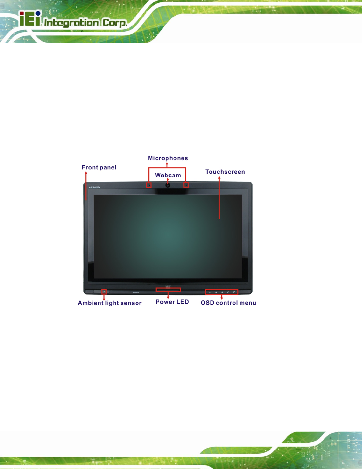
Figure 1-2: Front Panel ..................................................................................................................4
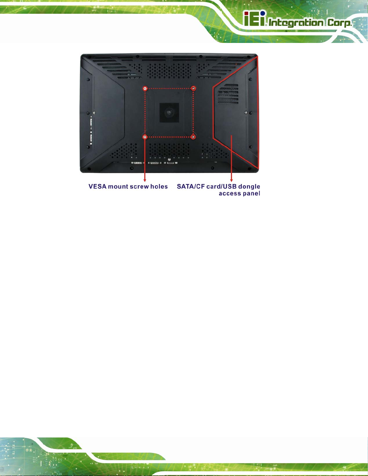
Figure 1-3: Rear Panel....................................................................................................................5
Figure 1-4: AFL2-W15A-N270 Bottom Panel................................................................................6
Figure 1-5: Dimensions..................................................................................................................9
Figure 2-1: HDD Access Panel Retention Screws.....................................................................14
Figure 2-2: HDD/CF Card Brackets Retention Screws..............................................................14
Figure 2-3: HDD Bracket Retention Screws...............................................................................15
Figure 2–4: HDD Installation........................................................................................................15
Figure 2–5: CompactFlash® Slot Location................................................................................16
Figure 2–6: CompactFlash® Install.............................................................................................16
Figure 2-7: USB Dongle Installation ...........................................................................................17
Figure 2-8: Plastic Back Cover Retention Screws ....................................................................18
Figure 2-9: Internal Aluminum Cover Retention Screws..........................................................19
Figure 2-10: CF Card Setup Jumper Location...........................................................................21
Figure 2-11: Clear CMOS Jumper Location ...............................................................................22
Figure 2-12: COM1 Pin 9 Setting Jumper Location...................................................................23
Figure 2-13: COM3 Pin 9 Setting Jumper Location...................................................................24
Figure 2-14: COM3 RX Function Select Jumper Location........................................................25
Figure 2-15: COM3 RS-232/422/485 Serial Port Select Jumper Location................................26
Figure 2-16: COM3 TX Function Select Jumper Location........................................................27
Figure 2-17: Arm Mount Retention Screw Holes.......................................................................29
Figure 2-18: Arm Mounting (ARM-11-RS)...................................................................................30
Figure 2-19: Cutout.......................................................................................................................31
Figure 2-20: Tighten the Panel Mounting Clamp Screws.........................................................32
Figure 2-21: Stand Mounting (Stand-A19)..................................................................................33
Figure 2-22: Wall Mount...............................................................................................................33
Figure 2-23: Wall-mounting Bracket...........................................................................................34
Figure 2-24: Chassis Support Screws........................................................................................35
Figure 2-25: Secure the Panel PC...............................................................................................36
Page viii
Page 9

AFL2-W15A-N270 Panel PC
Figure 2-26: AFL2-W15A-N270 Bottom Panel............................................................................36
Figure 2-27: LAN Connection......................................................................................................37
Figure 2-28: Serial Device Connector.........................................................................................38
Figure 2-29: USB Device Connection.........................................................................................38
Figure 2-30: VGA Connector .......................................................................................................39
Figure 4-1: SO-DIMM Module Installation...................................................................................80
Figure B-1: IEI One Key Recovery Tool Menu...........................................................................87
Figure B-2: Launching the Recovery Tool.................................................................................91
Figure B-3: Recovery Tool Setup Menu .....................................................................................92
Figure B-4: Command Mode........................................................................................................92
Figure B-5: Partition Creation Commands.................................................................................93
Figure B-6: Launching the Recovery Tool.................................................................................95
Figure B-7: System Configuration for Windows .......................................................................95
Figure B-8: Build-up Recovery Partition....................................................................................96
Figure B-9: Press any key to continue.......................................................................................96
Figure B-10: Press F3 to Boot into Recovery Mode..................................................................97
Figure B-11: Recovery Tool Menu ..............................................................................................97
Figure B-12: About Symantec Ghost Window...........................................................................98
Figure B-13: Symantec Ghost Path ............................................................................................98
Figure B-14: Select a Local Source Drive ..................................................................................99
Figure B-15: Select a Source Partition from Basic Drive .........................................................99
Figure B-16: File Name to Copy Image to ............................................................................... 100
Figure B-17: Compress Image.................................................................................................. 100
Figure B-18: Image Creation Confirmation............................................................................. 101
Figure B-19: Image Creation Process...................................................................................... 101
Figure B-20: Image Creation Complete................................................................................... 101
Figure B-21: Press Any Key to Continue................................................................................ 102
Figure B-22: Partitions for Linux.............................................................................................. 103
Figure B-23: System Configuration for Linux......................................................................... 104
Figure B-24: Access menu.lst in Linux (Text Mode).............................................................. 104
Figure B-25: Recovery Tool Menu ........................................................................................... 105
Figure B-26: Recovery Tool Main Menu.................................................................................. 106
Figure B-27: Restore Factory Default...................................................................................... 107
Figure B-28: Recovery Complete Window.............................................................................. 107
Figure B-29: Backup System.................................................................................................... 108
Page ix
Page 10

Figure B-30: System Backup Complete Window ................................................................... 108
Figure B-31: Restore Backup................................................................................................... 109
Figure B-32: Restore System Backup Complete Window..................................................... 109
Figure B-33: Symantec Ghost Window ................................................................................... 110
AFL2-W15A-N270 Panel PC
Page x
Page 11

AFL2-W15A-N270 Panel PC
List of Tables
Table 1-1: Model Variations...........................................................................................................3
Table 1-2: System Specifications..................................................................................................8
Table 2-1: Packing List.................................................................................................................13
Table 2-2: AFL2-W15A-N270 Jumpers........................................................................................20
Table 2-3: CF Card Setup Jumper Settings ...............................................................................20
Table 2-4: Clear CMOS Jumper Settings....................................................................................22
Table 2-5: COM1 Pin 9 Setting Jumper Settings.......................................................................23
Table 2-6: COM3 Pin 9 Setting Jumper Settings.......................................................................24
Table 2-7: COM3 RX Function Select Jumper Settings............................................................25
Table 2-8: COM3 RS-232/422/485 Serial Port Select Jumper Settings....................................26
Table 2-9: COM3 TX Function Select Jumper Settings.............................................................27
Table 2-10: RS-422 Pinouts .........................................................................................................27
Table 2-11: RS-485 Pinouts .........................................................................................................27
Table 3-1: BIOS Navigation Keys................................................................................................43
Page xi
Page 12

AFL2-W15A-N270 Panel PC
BIOS Menus
BIOS Menu 1: Main.......................................................................................................................44
BIOS Menu 2: Advanced..............................................................................................................45
BIOS Menu 3: CPU Configuration...............................................................................................46
BIOS Menu 4: IDE Configuration.................................................................................................47
BIOS Menu 5: IDE Master and IDE Slave Configuration...........................................................48
BIOS Menu 6: Super IO Configuration........................................................................................52
BIOS Menu 7: Hardware Health Configuration..........................................................................54
BIOS Menu 8: Power Configuration............................................................................................55
BIOS Menu 9: ACPI Settings .......................................................................................................56
BIOS Menu 10: APM Configuration.............................................................................................57
BIOS Menu 11: Remote Access Configuration..........................................................................60
BIOS Menu 12: USB Configuration.............................................................................................62
BIOS Menu 13: IEI Feature...........................................................................................................64
BIOS Menu 14: PCI/PnP Configuration.......................................................................................65
BIOS Menu 15: Boot.....................................................................................................................67
BIOS Menu 16: Boot Settings Configuration.............................................................................68
BIOS Menu 17: Boot Device Priority Settings ...........................................................................70
BIOS Menu 18: Hard Disk Drives ................................................................................................71
BIOS Menu 19: Security...............................................................................................................71
BIOS Menu 20: Advanced Chipset Settings ..............................................................................73
BIOS Menu 21: North Bridge Configuration ..............................................................................73
BIOS Menu 22:South Bridge Configuration...............................................................................76
BIOS Menu 23:Exit........................................................................................................................77
Page xii
Page 13

AFL2-W15A-N270 Panel PC
Chapter
1
1 Introduction
Page 1
Page 14
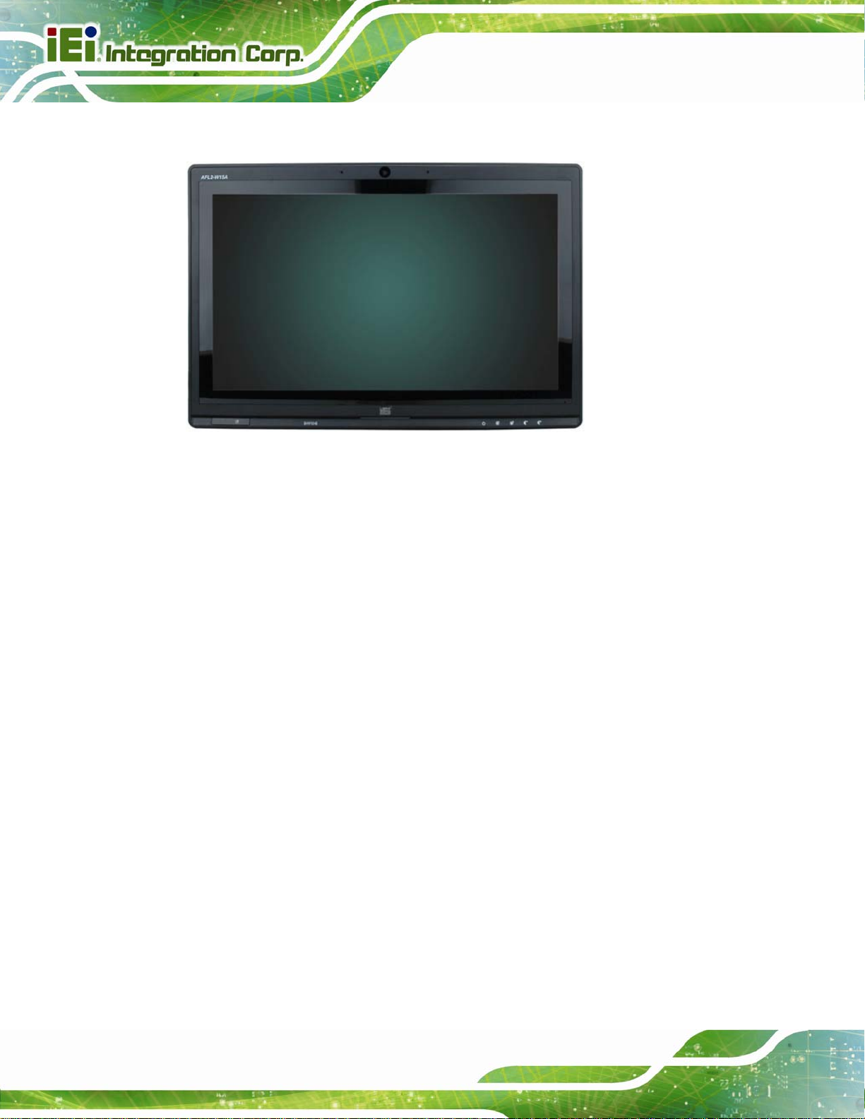
1.1 Overview
Figure 1-1: AFL2-W15A-N270
AFL2-W15A-N270 Panel PC
The Afolux panel PCs are all-in-one panel PCs with all the elements of a desktop
computer contained in a single, slim package, no bigger than a thick monitor. The Afolux
panel PCs can be mounted on a desktop monitor stand and save a huge amount of
desktop space by including all the computer components behind the screen. All models
include a touch screen interface.
The Afolux is a self-contained system, with all parts, excluding the power supply,
contained inside the casing allowing a completely interactive panel PC with only a single
power cable. External devices are connected wirelessly through an 802.11b/g/n wireless
adapter. Wired options are always available on the rear panel, with two serial ports and
USB ports for peripherals and a Gigabit Ethernet jack for networking.
The Afolux includes both audio and visual multimedia capabilities. All models have a VGA
output for connecting another monitor to the system, and audio outputs for external audio.
There is also a built-in 2-megapixel webcam and microphone.
Page 2
Page 15

AFL2-W15A-N270 Panel PC
1.2 Model Variations
There are two models of the AFL2-W15A-N270 series. The model variations are listed
below.
Model CPU Touchscreen
AFL2-W15A-N270/PC/1G-R20
AFL2-W15A-N270/R/1G-R20
Table 1-1: Model Variations
1.3 Features
Some of the standard features of the AFL2-W15A-N270 flat panel PC include:
Flat-bezel LCD with LED backlight
Projected capacitive type or resistive type touchscreen
Intel® Atom N270 processor
Pre-installed 1 GB 667 MHz or 800 MHz DDR2 SO-DIMM
(system max. 2 GB)
1.6 GHz Intel® Atom
processor N270
1.6 GHz Intel® Atom
processor N270
Projected capacitive type
Resistive type
Fully self-contained, only power from the external power supply required
802.11b/g/n wireless LAN
Gigabit Ethernet
Built-in two 1.5W speakers
Built-in 2-megapixel camera and microphone
IP 64 protection
RoHS compliant
Page 3
Page 16
1.4 External Overview
The AFL2-W15A-N270 consists of a screen and rear panel that covers the back, sides
and top. The rear panel contains a smaller access panel, all the cable connections and the
mounting holes.
1.4.1 Front Panel
The front side of the AFL2-W15A-N270 is a flat panel LCD screen surrounded by a plastic
frame.
AFL2-W15A-N270 Panel PC
Figure 1-2: Front Panel
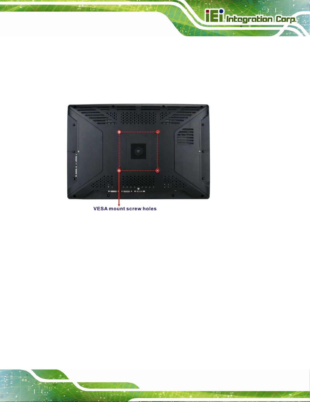
1.4.2 Rear Panel
The rear panel provides access to retention screw holes that support the wall mounting.
Page 4
Refer to
Figure 1-3.
Page 17
AFL2-W15A-N270 Panel PC
Figure 1-3: Rear Panel
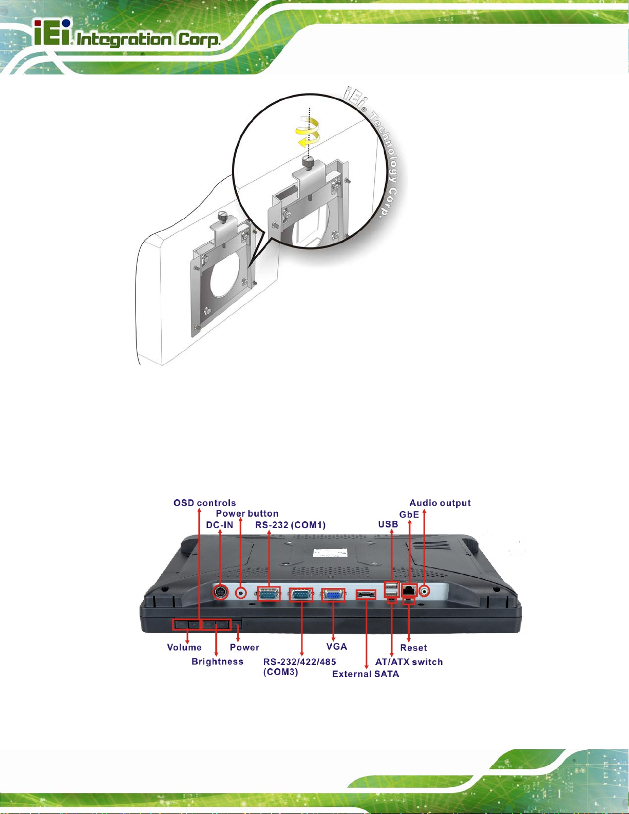
1.4.3 Bottom Panel
The bottom panel has the following slots, buttons and switches:
1 x Audio Line-out jack
1 x RJ-45 jack for Gigabit LAN
2 x USB ports
1 x External SATA port
1 x VGA port
1 x RS-232/422/485 serial port (COM3)
1 x RS-232 serial port (COM1)
1 x Power button
1 x Power input (12 V)
1 x Reset button
1 x AT/ATX power mode switch
1 x OSD keypad
Page 5
Page 18
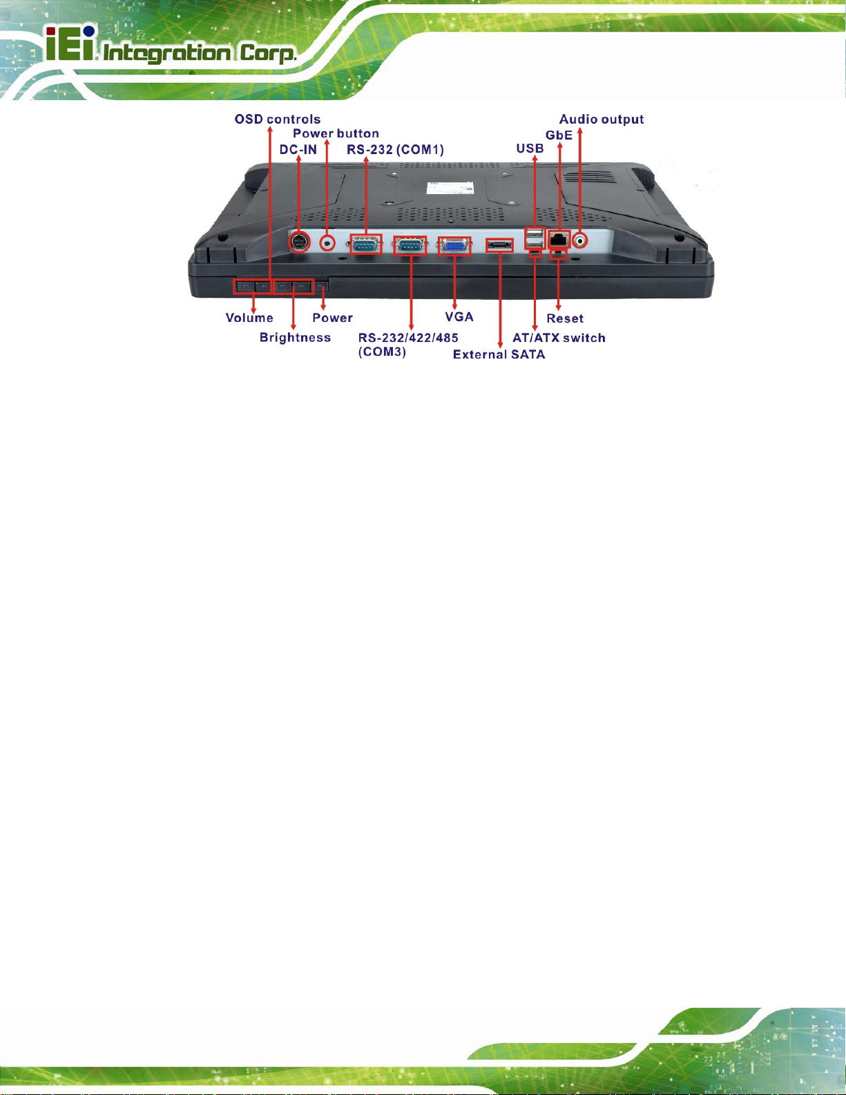
Figure 1-4: AFL2-W15A-N270 Bottom Panel
1.5 Internal Overview
AFL2-W15A-N270 Panel PC
All the components are contained under the rear panel. The internal components include
the touch panel module and the motherboard. The motherboard has memory, a wireless
module and a SATA hard drive bay.
Page 6
Page 19

AFL2-W15A-N270 Panel PC
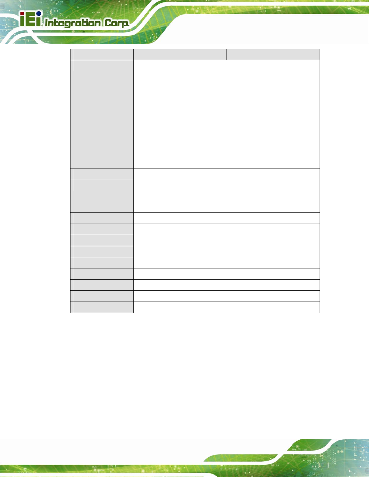
1.6 Specifications
The technical specifications for the AFL2-W15A-N270 systems are listed in Table 1-2.
SPECIFICATIONS AFL2-W15A-N270/R/1G-R20 AFL2-W15A-N270/PC/1G-R20
LCD Panel 15.6"
Resolution 1366 x 768
Brightness 300
Contrast Ratio 500:1
LCD Colors 16.7 million
Pixel Pitch 0.252 x 0.252
Viewing Angle (H/V) 170/160
Backlight MTBF 50000 hrs. (LED backlight)
Touchscreen R model: 5-wire resistive type (RS-232 interface)
PC model: Projected capacitive type (USB interface)
Mainboard AFLMB2-945GSE-N270
CPU 1.6 GHz Intel® Atom processor N270
Chipset Intel® 945GSE + ICH7M
Memory One 1 GB 667 MHz or 800 MHz DDR2 SO-DIMM preinstalled
(system max. 2 GB)
Ethernet Controller Realtek RTL8111CP PCIe GbE controller with ASF 2.0 support
Watchdog Timer Software programmable supports 1~255 sec. system reset
Audio Realtek ALC888 HD Audio codec
Two 1.5 W internal speakers
Camera 2-megapixel camera with low light function
Storage CF Type II
One 2.5” SATA HDD bay
OSD Function LCD on/off, brightness up/down, volume up/down
Wireless LAN 802.11b/g/n 2T2R module
RFID Reader
(Optional)
EM 125 KHz card reader or
Mifare 13.56 MHz card reader
Page 7
Page 20
SPECIFICATIONS AFL2-W15A-N270/R/1G-R20 AFL2-W15A-N270/PC/1G-R20
I/O 1 x Gigabit LAN
1 x Audio line-out
1 x Power input (12 V)
1 x RS-232
1 x RS-232/422/485
2 x USB ports
1 x VGA port
1 x External SATA
1 x Power Button
1 x Reset Button
Expansion Interface 1 x USB dongle
Power Adapter 60 W
90-246 VAC input 50/60 Hz
AFL2-W15A-N270 Panel PC
12 V DC output
Power Consumption 12V@4.25A (Intel® Atom N270 CPU with 667 MHz 2 GB DDR2 memory)
Mounting Feature VESA 100 mm x 100 mm
Operating Temp. -10ºC ~ 50ºC
Storage Temp. -20ºC ~ 60ºC
Humidity 10% ~ 95% (non-condensing)
Dimension (WxHxD) 400 mm x 267 mm x 54 mm
Net/Gross Weight 3.8 kg
Protection IP64 compliant front panel
EMC and Safety CE, FCC
Table 1-2: System Specifications
Page 8
Page 21
AFL2-W15A-N270 Panel PC
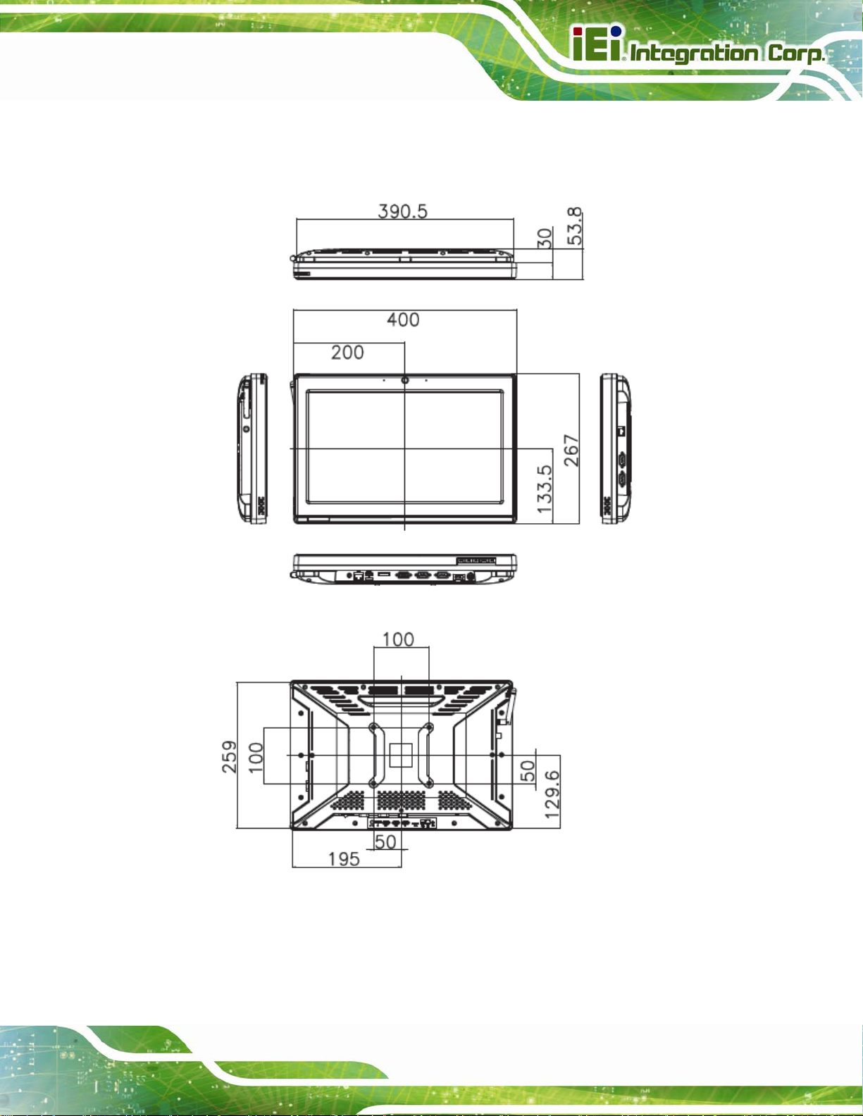
1.7 Dimensions
Width: 400 mm; Height: 267 mm; Depth: 54 mm.
Figure 1-5: Dimensions
Page 9
Page 22

AFL2-W15A-N270 Panel PC
Chapter
2
2 Installation
Page 10
Page 23

AFL2-W15A-N270 Panel PC
WARNING:
When installing the AFL2-W15A-N270, make sure to:
Turn the power off: Chance of electrocution. Turn off the monitor
and unplug it from the power supply.
Only let certified engineers change the hardware settings:
Incorrect settings can cause irreparable damage to the product.
Install the monitor with assistan ce: The product is very heavy and
may be damaged by drops and bumps. Two or more people should
install the panel PC.
Take anti-static precautions: Electrostatic discharge can destroy
electrical components and injure the user. Users must ground
themselves using an anti-static wristband or similar device.
The installation steps below should be followed in order.
Step 1: Unpack the flat panel PC
Step 2: Check all the required parts are included
Step 3: Install the hard drive
Step 4: Install the CompactFlash® card
Step 5: Mount the flat panel PC
Step 6: Connect peripheral devices to the bottom panel of the flat panel PC
Step 7: Connect the power cable
Step 8: Configure the system Step 0:
Page 11
Page 24
2.1 Unpack the Panel PC
To unpack the flat panel PC, follow the steps below:
WARNING!
Only remove the protective plastic cover stuck to the front screen after
installation. The plastic layer protects the monitor surface during
installation process.
Step 1: Carefully cut the tape sealing the box. Only cut deep enough to break the tape.
Step 2: Open the outside box.
Step 3: Carefully cut the tape sealing the box. Only cut deep enough to break the tape.
AFL2-W15A-N270 Panel PC
Step 4: Open the inside box.
Step 5: Lift the monitor out of the boxes.
Step 6: Remove the peripheral parts box from the main box. Step 0:
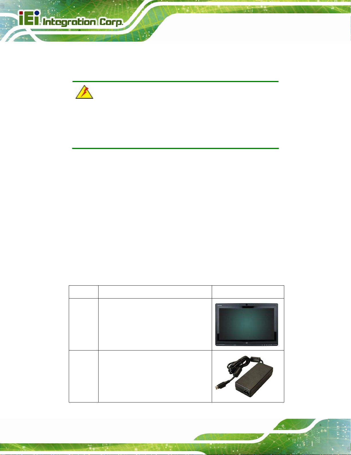
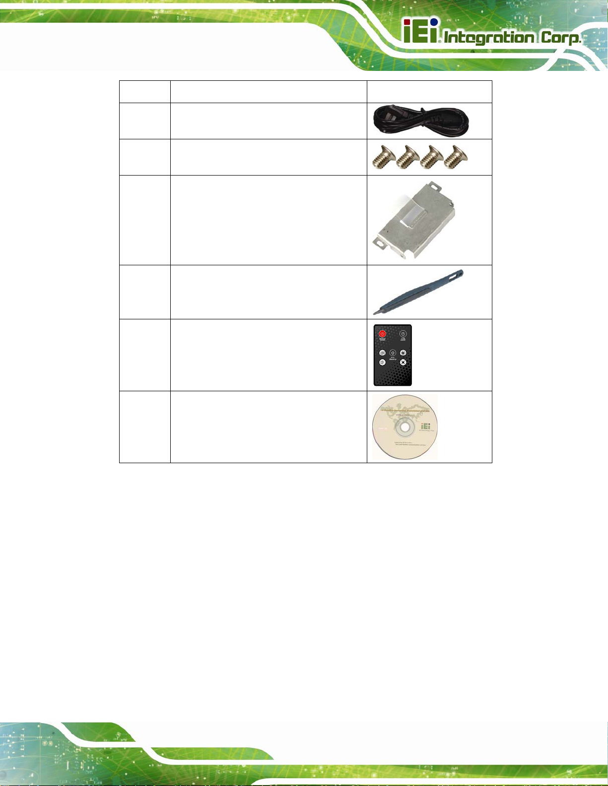
2.2 Packing List
The AFL2-W15A-N270 flat panel PC is shipped with the following components:
Quantity Item Image
1 AFL2-W15A-N270
1 Power adapter
Page 12
Page 25
AFL2-W15A-N270 Panel PC
Quantity Item Image
1 Power cord
4 Screws
1 HDD bracket
1 Touch screen pen
1 Remote Control
1 Utility CD
Table 2-1: Packing List
If any of these items are missing or damaged, contact the distributor or sales
representative immediately.
2.3 Hard Drive Installation
This section outlines the installation of the hard drive in the AFL2-W15A-N270. To install
the hard drive, please follow the steps below:
Step 1: Unfasten the right plastic side access panel (SATA/CF card/USB dongle access
panel) retention screws and remove the right plastic side access panel
Figure 2-1).
(
Page 13
Page 26
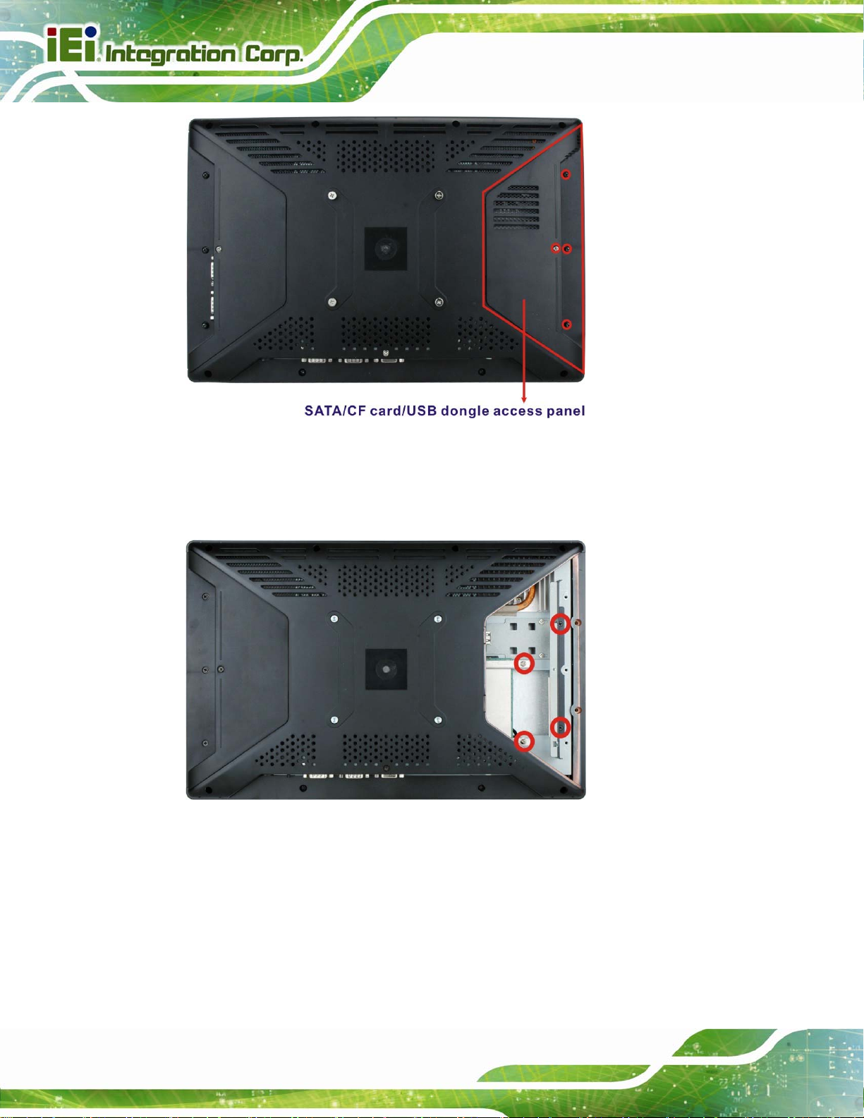
Figure 2-1: HDD Access Panel Retention Screws
Step 2: Locate the HDD/CF card brackets. Unfasten screws and removed brackets
AFL2-W15A-N270 Panel PC
Figure 2-2).
(
Figure 2-2: HDD/CF Card Brackets Retention Screws
Step 3: Attach the HDD brackets to the HDD. To do this, align the two retention screw
holes in the both sides of the HDD bracket with the retention screw holes on the
Page 14
sides of the HDD. Insert two retention screws into the HDD bracket
Figure 2-3).
(
Page 27
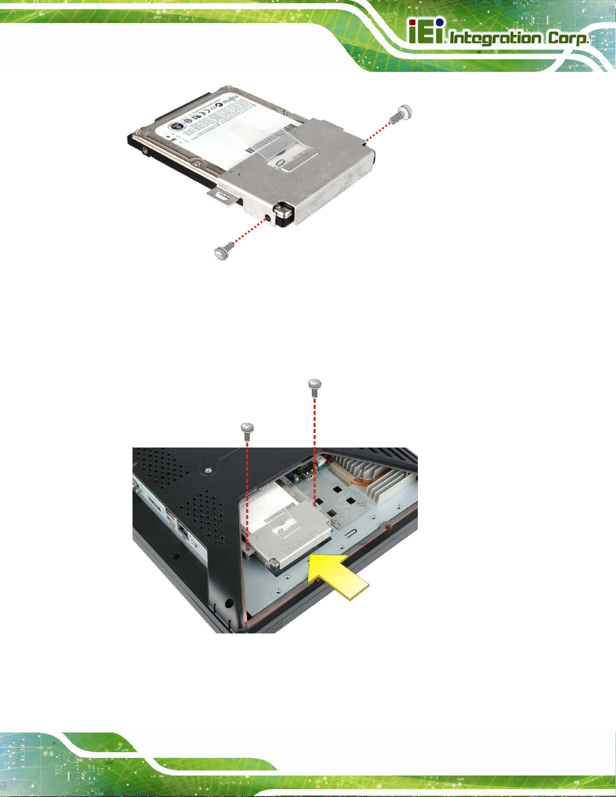
AFL2-W15A-N270 Panel PC
Figure 2-3: HDD Bracket Retention Screws
Step 4: Insert the SATA connector end of the HDD into the bracket to connect the
motherboard SATA connector to the hard drive SATA connector.
Step 5: Install the two retention screws (removed in Step 2) to secure the HDD.
Figure 2–4: HDD Installation
Step 6: Replace the brackets, covers and screws.Step 0:
Page 15
Page 28
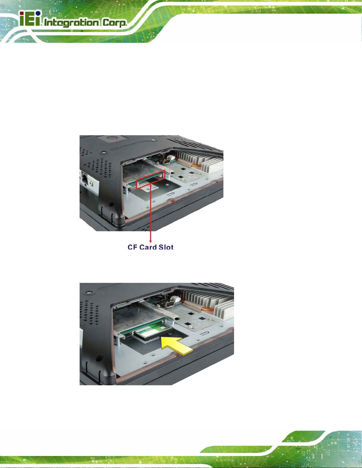
2.4 CompactFlash® Installation
The installation for a CompactFlash® card is described in this section.
Step 1: Remove the access panel and brackets as described in the HDD installation
instructions.
AFL2-W15A-N270 Panel PC
Step 2: Locate the CompactFlash® slot as shown in
Figure 2–5: CompactFlash® Slot Location
Step 3: Install the CompactFlash® card into the slot (see
Figure 2–5.
Figure 2–6).
Page 16
Figure 2–6: CompactFlash® Install
Step 4: Replace the brackets, access panel and screws.Step 0:
Page 29
AFL2-W15A-N270 Panel PC
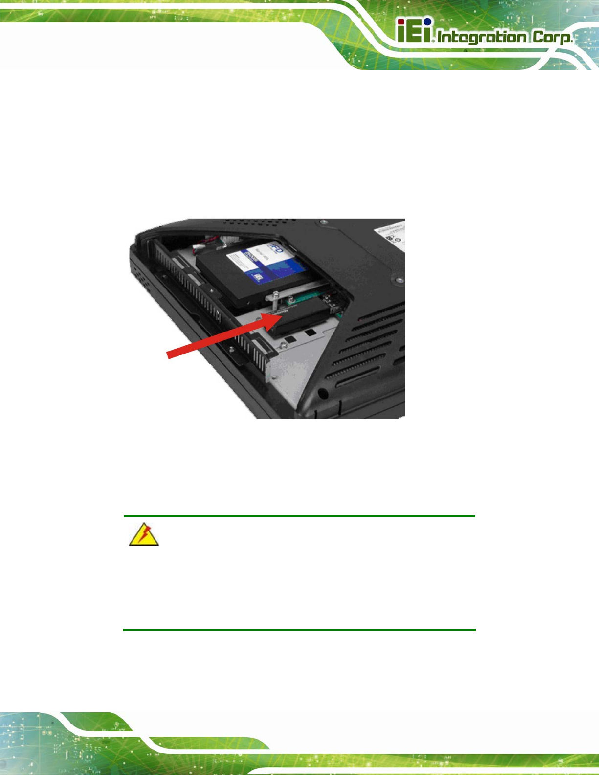
2.5 USB Dongle Installation
The installation for an USB dongle is described in this section.
Step 1: Remove the access panel and brackets as described in the HDD installation
instructions.
Step 2: Locate the USB dongle connector and install the USB dongle as shown below.
Figure 2-7: USB Dongle Installation
Step 3: Replace the bracket, access panel and screws.
2.6 Cover Removal
WARNING!
Turn off the power before removing the back cover. Risk of
electrocution. Severe damage to the product and injury to the body
may occur if internal parts are touched while the power is still on.
Page 17
Page 30
AFL2-W15A-N270 Panel PC
WARNING!
Take antistatic precautions when working on the internal
components. Some internal components are easily damaged or
destroyed by electrostatic discharge. Take antistatic precautions to
prevent electrostatic discharge.
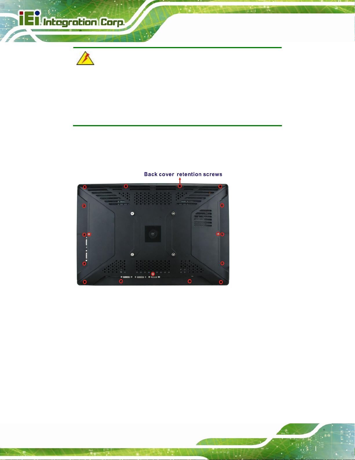
To access the internal components, the plastic back cover and the internal aluminum
cover of the AFL2-W15A-N270 must be removed. To remove the back cover, unfasten the
retention screws and then lift the cover to remove.
Page 18
Figure 2-8: Plastic Back Cover Retention Screws
To remove the internal aluminum cover, unfasten the eight retention screws and then lift
the cover to remove.
Page 31
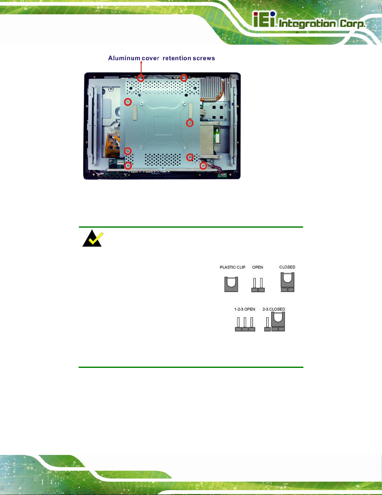
AFL2-W15A-N270 Panel PC
Figure 2-9: Internal Aluminum Cover Retention Screws
2.7 Jumper Settings
NOTE:
A jumper is a metal bridge used to
close an electrical circuit. It consists of
two or three metal pins and a small
metal clip (often protected by a plastic
cover) that slides over the pins to
connect them. To CLOSE/SHORT a
jumper means connecting the pins of
the jumper with the plastic clip and to OPEN a jumper means removing
the plastic clip from a jumper.
The following jumpers can be found on the motherboard installed in the AFL2-W15A-N270.
Before the AFL2-W15A-N270 is installed, the jumpers must be set in accordance with the
desired configuration. The jumpers on the AFL2-W15A-N270 motherboard are listed in
Table 2-2.
Page 19
Page 32
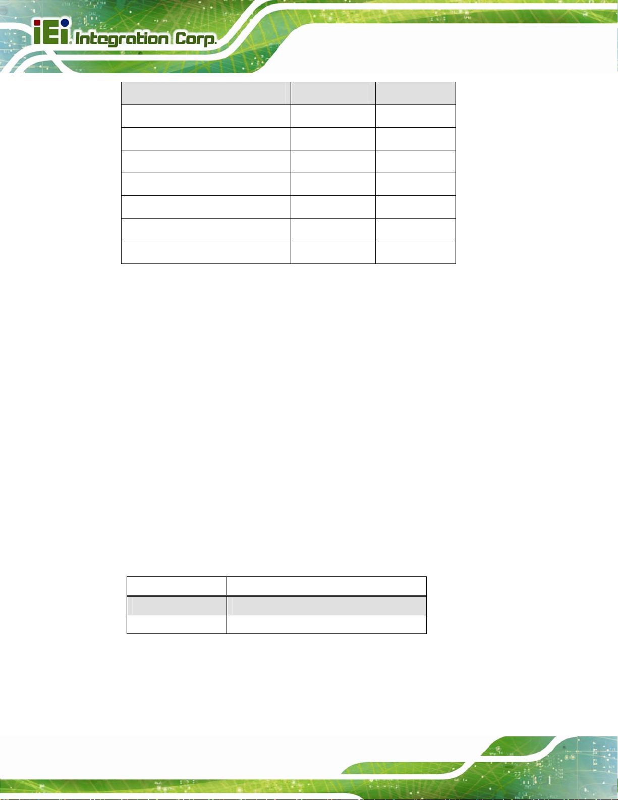
Description Label Type
CF card setup JCF1 2-pin header
Clear CMOS J_CMOS1 3-pin header
COM1 Pin 9 setting JP5 10-pin header
COM3 Pin 9 setting JP7 6-pin header
COM3 RX RS-232/422/485 select JP8 8-pin header
COM3 RS-232/422/485 select JP10 12-pin header
COM3 TX RS-422/485 select JP11 6-pin header
Table 2-2: AFL2-W15A-N270 Jumpers
2.7.1 Access the Jumpers
AFL2-W15A-N270 Panel PC
To access the jumpers, please remove the back panel and the internal aluminum chassis.
To remove the back panel, please refer to Section
2.6.
2.7.2 CF Card Setup
Jumper Label: JCF1
Jumper Type:
Jumper Settings:
Jumper Location:
The CF Card Setup jumper sets the CF Type I card or CF Type II cards as either the slave
device or the master device. CF Card Setup jumper settings are shown in
CF Setup Description
Open Master (Default)
Closed Slave
Table 2-3: CF Card Setup Jumper Settings
2-pin header
Table 2-3
See
Figure 2-10
See
Table 2-3.
Page 20
The CF Card Setup jumper location is shown in Figure 2-10.
Page 33

AFL2-W15A-N270 Panel PC
Figure 2-10: CF Card Setup Jumper Location
2.7.3 Clear CMOS Jumper
Jumper Label: J_CMOS1
Jumper Type:
Jumper Settings:
Jumper Location:
If the AFL2-W15A-N270 fails to boot due to improper BIOS settings, the clear CMOS
jumper clears the CMOS data and resets the system BIOS information. To do this, use the
jumper cap to close the pins for a few seconds then remove the jumper clip.
If the “CMOS Settings Wrong” message is displayed during the boot up process, the fault
may be corrected by pressing the F1 to enter the CMOS Setup menu. Do one of the
following:
Enter the correct CMOS setting
Load Optimal Defaults
Load Failsafe Defaults.
3-pin header
Table 2-4
See
Figure 2-11
See
After having done one of the above, save the changes and exit the CMOS Setup menu.
The clear CMOS jumper settings are shown in
Table 2-4.
Page 21
Page 34

Clear CMOS Description
Short 1 - 2 Keep CMOS Setup (Default)
Short 2 - 3 Clear CMOS Setup
AFL2-W15A-N270 Panel PC
Table 2-4: Clear CMOS Jumper Settings
The location of the clear CMOS jumper is shown in Figure 2-11 below.
Figure 2-11: Clear CMOS Jumper Location
2.7.4 COM 1 Port Pin 9 Select
Jumper Label: JP5
Jumper Type:
Jumper Settings:
Jumper Location:
The jumper configures pin 9 on COM1 connector. Pin 9 on the COM1 connector can be
set as the ring (RI) signal, +5 V or +12 V. The COM1 Pin 9 Setting jumper selection
options are shown in
JP5 Description
Short 1-3 COM1 RI Pin use +12 V
Short 5-7 COM1 RI Pin use RI
10-pin header
Table 2-5
See
Figure 2-12
See
Table 2-5.
Page 22
Page 35

AFL2-W15A-N270 Panel PC
Short 7-9 COM1 RI Pin use +5 V (Default)
Table 2-5: COM1 Pin 9 Setting Jumper Settings
The COM1 Pin 9 Setting jumper locations are shown in Figure 2-12 below.
Figure 2-12: COM1 Pin 9 Setting Jumper Location
2.7.5 COM 3 Port Pin 9 Select
Jumper Label: JP7
Jumper Type:
Jumper Settings:
Jumper Location:
The jumper configures pin 9 on COM3 DB-9 connectors. Pin 9 on the COM3 DB-9
connector can be set as the ring (RI) signal, +5 V or +12 V. The COM3 Pin 9 Setting
jumper selection options are shown in
JP7 Description
Short 1-2 COM3 RI Pin use +12 V
Short 3-4 COM3 RI Pin use RI (Default)
6-pin header
Table 2-6
See
Figure 2-13
See
Table 2-5.
Page 23
Page 36

Short 5-6 COM3 RI Pin use +5 V
AFL2-W15A-N270 Panel PC
Table 2-6: COM3 Pin 9 Setting Jumper Settings
The COM3 Pin 9 Setting jumper locations are shown in Figure 2-12 below.
Figure 2-13: COM3 Pin 9 Setting Jumper Location
2.7.6 COM3 RX Function Select Jumper
Jumper Label: JP8
Jumper Type:
Jumper Settings:
Jumper Location:
The COM3 RX Function Select jumper sets the communication protocol used by the RX
serial communications port COM3 as RS-232, RS-422 or RS-485. The COM3 RX
Function Select jumper settings are shown in
JP8 Description
Short 1-2 DET BIOS RS-232/422/485
Short 3-4 RS-232 (Default)
8-pin header
Table 2-7
See
Figure 2-14
See
Table 2-7.
Page 24
Short 5-6 RS-422
Page 37

AFL2-W15A-N270 Panel PC
Short 7-8 RS-485
Table 2-7: COM3 RX Function Select Jumper Settings
The COM3 RX Function Select jumper location is shown in Figure 2-14.
Figure 2-14: COM3 RX Function Select Jumper Location
2.7.7 COM3 RS-232/422/485 Serial Port Select Jumper
Jumper Label: JP10
Jumper Type:
Jumper Settings:
Jumper Location:
The COM3 RS-232/422/485 Serial Port Select jumper sets the communication protocol
used by the second serial communications port (COM3) as RS-232, RS-422 or RS-485.
The COM3 RS-232/422/485 Serial Port Select settings are shown in
JP10 Description
Short 1-2, 4-5, 7-8, 10-11 RS-232 (Default)
Short 2-3, 5-6, 8-9, 11-12 RS-422/485
12-pin header (four 3-pin headers combined)
Table 2-8
See
Figure 2-15
See
Table 2-8.
Page 25
Page 38

Table 2-8: COM3 RS-232/422/485 Serial Port Select Jumper Settings
The COM3 RS-232/422/485 Serial Port Select jumper location is shown in Figure 2-15.
AFL2-W15A-N270 Panel PC
Figure 2-15: COM3 RS-232/422/485 Serial Port Select Jumper Location
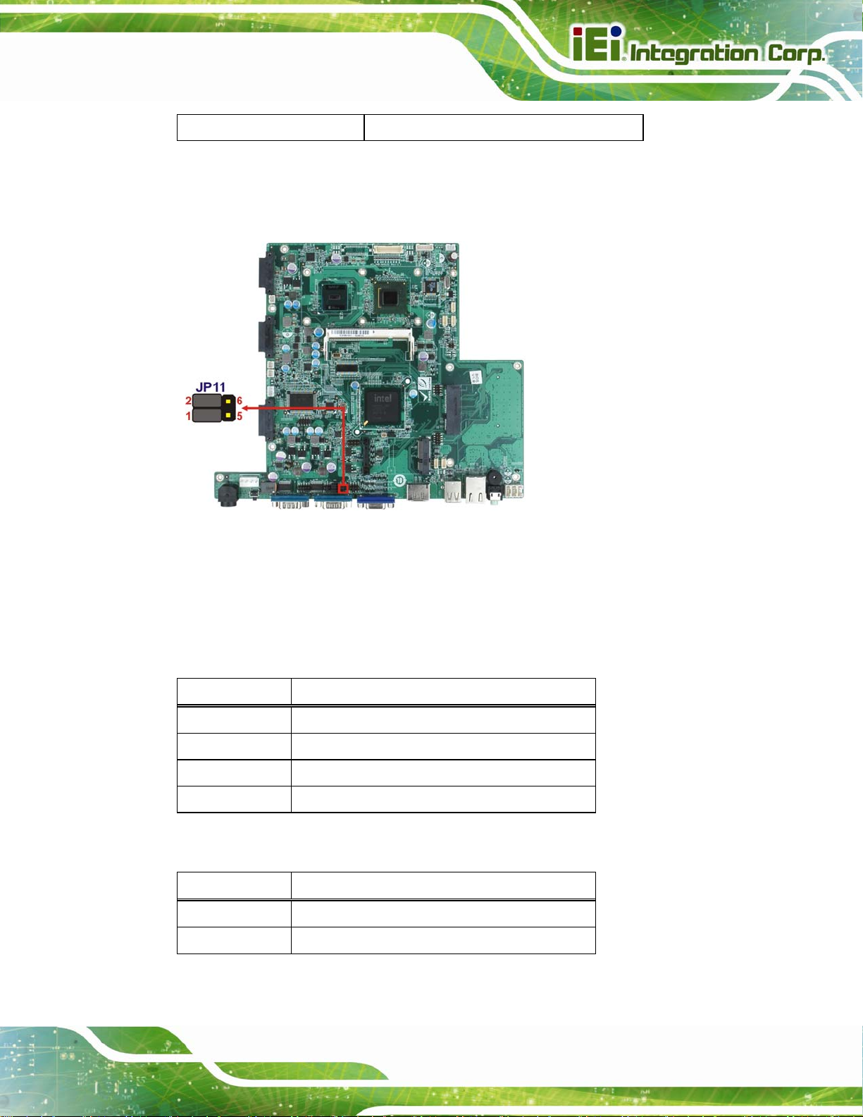
2.7.8 COM3 TX Function Select Jumper
Jumper Label: JP11
Jumper Type:
Jumper Settings:
Jumper Location:
The COM3 TX Function Select jumper configures the TX pin on COM3 serial port
connector as RS-422 as an RS-485. The COM3 TX Function Select jumper selection
options are shown in
JP11 Description
Short 1 – 3 RS-422 TX-
Short 2 – 4 RS-422 TX+
6-pin header
Table 2-9
See
Figure 2-16
See
Table 2-9.
Page 26
Short 3 – 5 RS-485 D-
Page 39
AFL2-W15A-N270 Panel PC
Short 4 – 6 RS-485 D+
Table 2-9: COM3 TX Function Select Jumper Settings
The COM3 TX Function Select jumper location is shown in Figure 2-16 below.
Figure 2-16: COM3 TX Function Select Jumper Location
2.7.8.1 COM3 RS-422 and RS-485 Pinouts
The pinouts for RS-422 and RS-485 operation of external serial port COM 3 are detailed
below.
COM 3 RS-422 Description
Pin 1 TXPin 2 TX+
Pin 6 RXPin 7 RX+
Table 2-10: RS-422 Pinouts
COM 3 RS-485 Description
Pin 1 DataPin 2 Data+
Table 2-11: RS-485 Pinouts
Page 27
Page 40

2.8 Mounting the System
WARNING!
The panel PC is very heavy. Two or more people should mount the
panel PC. Dropping or bumping the panel PC during installation can
cause serious or irreparable damage to the panel PC.
The following installation options are available:
Arm mounting
Panel mounting
Stand mounting
Wall mounting
AFL2-W15A-N270 Panel PC
The installation instructions are included with the stand, arm or mount.
2.8.1 Arm Mounting
The AFL2-W15A-N270 is VESA (Video Electronics Standards Association) compliant and
can be mounted on an arm with a 100 mm interface pad. To mount the AFL2-W15A-N270
on an arm, please follow the steps below.
Step 1: The arm is a separately purchased item. Please correctly mount the arm onto
the surface it uses as a base. To do this, refer to the installation documentation
that came with the mounting arm.
NOTE:
When purchasing the arm please ensure that it is VESA compliant and
that the arm has a 100 mm interface pad. If the mounting arm is not
VESA compliant it cannot be used to support the AFL2-W15A-N270.
Page 28
Page 41
AFL2-W15A-N270 Panel PC
Step 2: Once the mounting arm has been firmly attached to its surface, lift the
AFL2-W15A-N270 onto the interface pad of the mounting arm.
Step 3: Align the retention screw holes on the mounting arm interface with those in the
AFL2-W15A-N270. The AFL2-W15A-N270 arm mount retention screw holes are
shown in
Figure 2-17: Arm Mount Retention Screw Holes
Step 4: Secure the AFL2-W15A-N270 to the interface pad by inserting four retention
Figure 2-17.
screws through the mounting arm interface pad and into the AFL2-W15A-N270.
Page 29
Page 42

AFL2-W15A-N270 Panel PC
Figure 2-18: Arm Mounting (ARM-11-RS)
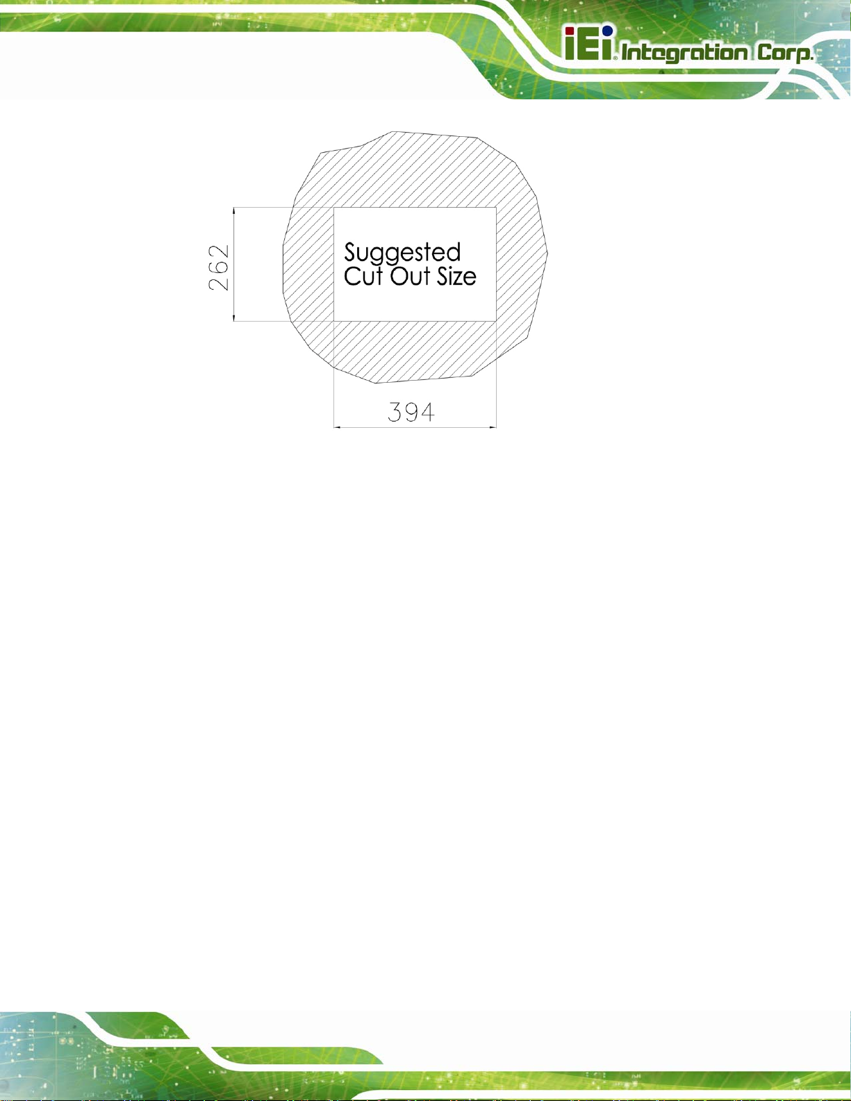
2.8.2 Panel Mounting
To mount the panel PC into a panel, please follow the steps below.
Step 1: Select the position on the panel to mount the flat panel PC.
Step 2: Cut out a section corresponding to the size shown below. The size must be
smaller then the outer edge. Recommended cutout sizes are shown below.
Page 30
Page 43
AFL2-W15A-N270 Panel PC
Figure 2-19: Cutout
Step 3: Slide the flat panel PC through the hole until the aluminum frame is flush against
the panel.
Step 4: Align the panel mounting bracket screw holes with the VESA mounting holes on
the rear of the panel PC.
Step 5: Secure the two panel mounting brackets to the rear of the panel PC by inserting
the four retention screws into the VESA mounting holes (
Step 6: Insert the panel mounting clamps into the pre-formed holes along the two edges
of the panel mounting brackets (
mounting clamps for the AFL2-W15A-N270.
Step 7: Tighten the screws that pass through the panel mounting clamps until the plastic
caps at the front of all the screws are firmly secured to the panel
Figure 2-20
). There are a total of 4 panel
Figure 2-20
).
Figure 2-20
(
).
Page 31
Page 44

AFL2-W15A-N270 Panel PC
Figure 2-20: Tighten the Panel Mounting Clamp Screws
2.8.3 Stand Mounting
To mount the AFL2-W15A-N270 using the stand mounting kit, please follow the steps
below.
Step 1: Locate the screw holes on the rear of the AFL2-W15A-N270. This is where the
bracket will be attached.
Step 2: Align the bracket with the screw holes.
Step 3: To secure the bracket to the AFL2-W15A-N270 insert the retention screws into
the screw holes and tighten them.
Page 32
Page 45

AFL2-W15A-N270 Panel PC
Figure 2-21: Stand Mounting (Stand-A19)
2.8.4 Wall Mounting
To mount the flat panel PC onto the wall, please follow the steps below.
Figure 2-22: Wall Mount
Step 1: Select the location on the wall for the wall-mounting bracket.
Step 2: Carefully mark the locations of the four brackets screw holes on the wall.
Page 33
Page 46
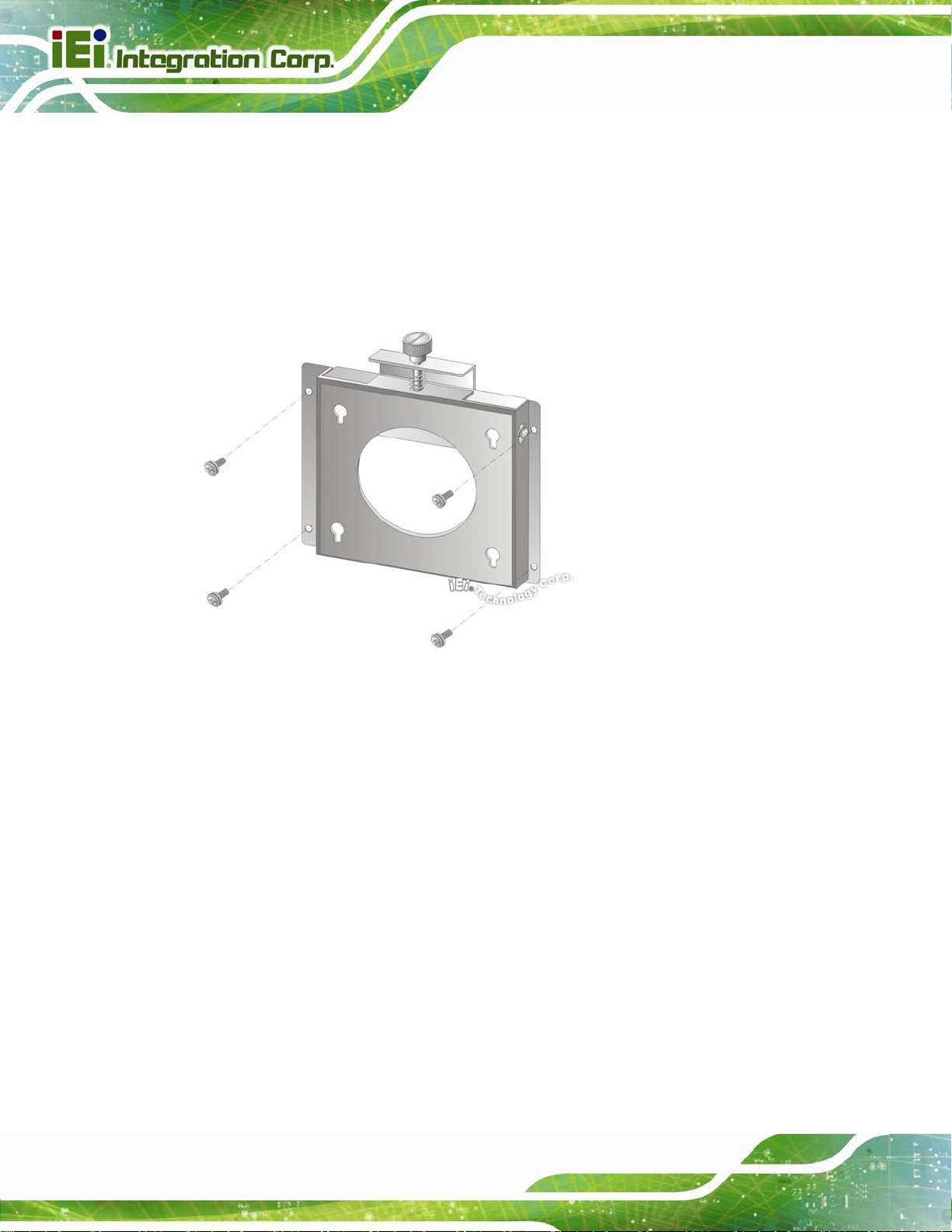
Step 3: Drill four pilot holes at the marked locations on the wall for the bracket retention
screws.
Step 4: Align the wall-mounting bracket screw holes with the pilot holes.
Step 5: Secure the mounting-bracket to the wall by inserting the retention screws into
AFL2-W15A-N270 Panel PC
the four pilot holes and tightening them (
Figure 2-23: Wall-mounting Bracket
Step 6: Insert the four monitor mounting screws provided in the wall mounting kit into the
Figure 2-23).
Page 34
four screw holes on the real panel of the flat panel PC and tighten until the screw
shank is secured against the rear panel (
Step 7: Align the mounting screws on the monitor rear panel with the mounting holes on
the bracket.
Step 8: Carefully insert the screws through the holes and gently pull the monitor
downwards until the monitor rests securely in the slotted holes (
Ensure that all four of the mounting screws fit snuggly into their respective
slotted holes.
Figure 2-24).
Figure 2-24).
Page 47

AFL2-W15A-N270 Panel PC
Figure 2-24: Chassis Support Screws
NOTE:
In the diagram below the bracket is already installed on the wall.
Step 9: Secure the panel PC by fastening the retention screw of the wall-mounting
bracket. (
Figure 2-25).
Page 35
Page 48
AFL2-W15A-N270 Panel PC
Figure 2-25: Secure the Panel PC
2.9 Bottom Panel Connectors
The bottom panel connectors extend the capabilities of the panel PC but are not essential
for operation (except power).
Page 36
Figure 2-26: AFL2-W15A-N270 Bottom Panel
Page 49

AFL2-W15A-N270 Panel PC
2.9.1 LAN Connection
The RJ-45 connector enables connection to an external network. To connect a LAN cable
with an RJ-45 connector, please follow the instructions below.
Step 1: Locate the RJ-45 connector on the bottom panel of the AFL2-W15A-N270.
Step 2: Align the connectors. Align the RJ-45 connector on the LAN cable with the
RJ-45 connector on the bottom panel of the AFL2-W15A-N270. See
Figure 2-27.
Figure 2-27: LAN Connection
Step 3: Insert the LAN cable RJ-45 connector. Once aligned, gently insert the LAN
cable RJ-45 connector into the onboard RJ-45 port. Step 0:
2.9.2 Serial Device Connection
The serial device connectors are for connecting serial devices to the AFL2-W15A-N270.
Follow the steps below to connect a serial device to the AFL2-W15A-N270 panel PC.
Step 1: Locate the DB-9 connector. The location of the DB-9 connector is shown in
Figure 2-26.
Step 2: Insert the serial connector. Insert the DB-9 connector of a serial device into
the DB-9 connector on the bottom panel. See
Figure 2-28.
Page 37
Page 50

Figure 2-28: Serial Device Connector
Step 3: Secure the connector. Secure the serial device connector to the external
AFL2-W15A-N270 Panel PC
interface by tightening the two retention screws on either side of the connector.
2.9.3 USB Device Connection
To connect USB devices to the AFL2-W15A-N270, please follow the instructions below.
Step 1: Located the USB connectors. The locations of the USB connectors are shown
Figure 2-26.
in
Step 2: Align the connectors. Align the USB device connector with one of the
connectors on the bottom panel. See
Figure 2-29.
Step 0:
Page 38
Figure 2-29: USB Device Connection
Page 51

AFL2-W15A-N270 Panel PC
Step 3: Insert the device connector. Once aligned, gently insert the USB device
connector into the onboard connector. Step 0:
2.9.4 VGA Monitor Connection
The VGA output can be connected to an external VGA monitor. To connect the VGA
monitor to the AFL2-W15A-N270, please follow the instructions below.
Step 1: Locate the female DB-15 connector. The location of the female DB-15
connector is shown in
Step 2: Align the VGA connector. Align the male DB-15 connector on the VGA screen
cable with the female DB-15 connector on the external peripheral interface.
Step 3: Insert the VGA connector. Once the connectors are properly aligned with the
insert the male connector from the VGA screen into the female connector on the
AFL2-W15A-N270. See
Figure 2-26.
Figure 2-30.
Figure 2-30: VGA Connector
Step 4: Secure the connector. Secure the DB-15 VGA connector from the VGA
monitor to the external interface by tightening the two retention screws on either
side of the connector. Step 0:
Page 39
Page 52

2.10 Power Connection
The power cable connects the panel PC to the power supply. The power cable is required
for operation of the panel PC.
Step 1: Connect one end to the panel PC.
Step 2: Connect the other end to the included power supply Step 0:
2.11 Driver Installation
NOTE:
The content of the CD may vary throughout the life cycle of the product
and is subject to change without prior notice. Visit the IEI website or
AFL2-W15A-N270 Panel PC
contact technical support for the latest updates.
The following drivers can be installed on the system. Each driver is in its own directory on
the driver CD:
Chipset driver
Graphics driver
LAN driver
Audio driver
Touchscreen driver
Keypad utility driver
Wireless LAN card driver
NOTE:
There two kinds of touchscreen driver in the driver CD. Please follow
Page 40
the guideline below to install the correct driver for the system:
Multi Touch for the AFL2-W15A-N270/PC/1G-R20
Single Touch for the AFL2-W15A-N270/R/1G-R20
Page 53

AFL2-W15A-N270 Panel PC
Chapter
3
3 BIOS Setup
Page 41
Page 54

3.1 Introduction
The BIOS is programmed onto the BIOS chip. The BIOS setup program allows changes to
certain system settings. This chapter outlines the options that can be changed.
3.1.1 Starting Setup
The AMI BIOS is activated when the computer is turned on. The setup program can be
activated in one of two ways.
AFL2-W15A-N270 Panel PC
1. Press the D
2. Press the D
appears on the screen. 0.
If the message disappears before the D
again.
ELETE key as soon as the system is turned on or
ELETE key when the “Press Del to enter SETUP” message
ELETE key is pressed, restart the computer and try
3.1.2 Using Setup
Use the arrow keys to highlight items, press ENTER to select, use the PageUp and
PageDown keys to change entries, press F1 for help and press E
keys are shown in.
Key Function
Up arrow Move to previous item
Down arrow Move to next item
Left arrow Move to the item on the left hand side
SC to quit. Navigation
Page 42
Right arrow Move to the item on the right hand side
Esc key Main Menu – Quit and not save changes into CMOS
Status Page Setup Menu and Option Page Setup Menu --
Exit current page and return to Main Menu
Page Up key Increase the numeric value or make changes
Page Dn key Decrease the numeric value or make changes
F1 key General help, only for Status Page Setup Menu and Option
Page Setup Menu
Page 55

AFL2-W15A-N270 Panel PC
Key Function
F2 /F3 key Change color from total three colors. F2 to select color
forward.
F10 key Save all the CMOS changes, only for Main Menu
Table 3-1: BIOS Navigation Keys
3.1.3 Getting Help
When F1 is pressed a small help window describing the appropriate keys to use and the
possible selections for the highlighted item appears. To exit the Help Window press E
the F1 key again.
3.1.4 Unable to Reboot After Configuration Changes
If the computer cannot boot after changes to the system configuration is made, CMOS
defaults. Use the jumper described in Section
2.7.3.
3.1.5 BIOS Menu Bar
The menu bar on top of the BIOS screen has the following main items:
Main – Changes the basic system configuration.
Advanced – Changes the advanced system settings.
PCIPnP – Changes the advanced PCI/PnP Settings
Boot – Changes the system boot configuration.
Security – Sets User and Supervisor Passwords.
Chipset – Changes the chipset settings.
SC or
Exit – Selects exit options and loads default settings
The following sections completely describe the configuration options found in the menu
items at the top of the BIOS screen and listed above.
Page 43
Page 56

AFL2-W15A-N270 Panel PC
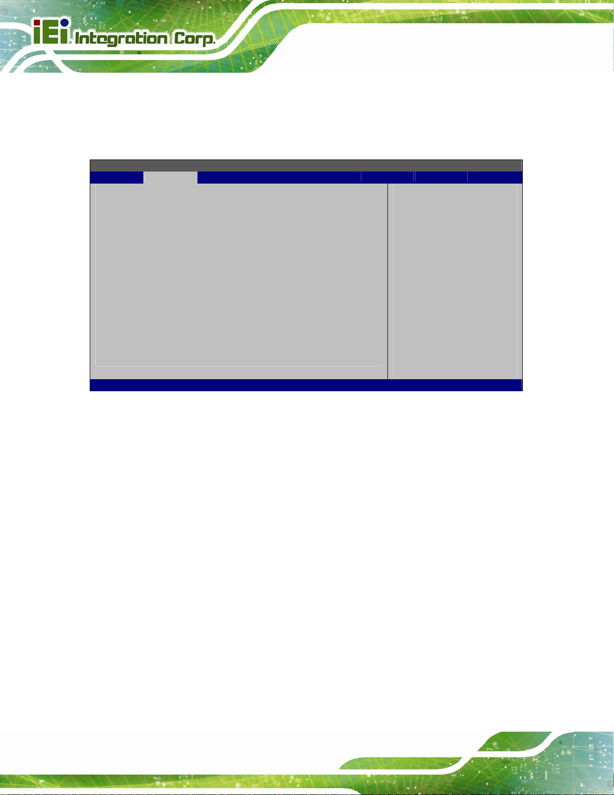
3.2 Main
The Main BIOS menu (BIOS Menu 1) appears when the BIOS Setup program is entered.
The Main menu gives an overview of the basic system information.
BIOS SETUP UTILITY
Main Advanced PCIPNP Boot Security Chipset Power Exit
System Overview
⎯⎯⎯⎯⎯⎯⎯⎯⎯⎯⎯⎯⎯⎯⎯⎯⎯⎯⎯⎯⎯⎯⎯⎯⎯⎯⎯⎯⎯⎯⎯
AMIBIOS
Version :08.00.15
Build Date :04/15/13
ID: :H754MR11
Processor
Genuine Intel(R) CPU N270 @ 1.60GHz
Speed :1600 MHz
Count :1
System Memory
Size :1016MB
System Time [14:20:27]
System Time [Tue 08/28/2013]
v02.61 ©Copyright 1985-2006, American Megatrends, Inc.
Use [ENTER], [TAB] or
[SHIFT-TAB] to select a
field.
Use [+] or [-] to
configure system time.
Select Screen
↑ ↓ Select Item
Tab Go to SubScreen
F1 General Help
F10 Save and Exit
ESC Exit
BIOS Menu 1: Main
System Overview
The System Overvie w lists a brief summary of different system components. The fields in
System Overview cannot be changed. The items shown in the system overview include:
AMI BIOS: Displays auto-detected BIOS information
o Version: Current BIOS version
o Build Date: Date the current BIOS version was made
o ID: Installed BIOS ID
Processor: Displays auto-detected CPU specifications
o Type: Names the currently installed processor
o Speed: Lists the processor speed
o Count: The number of CPUs on the motherboard
System Memory: Displays the auto-detected system memory.
o Size: Lists memory size
Page 44
Page 57

AFL2-W15A-N270 Panel PC
The System Overview field also has two user configurable fields:
System Time [xx:xx:xx]
Use the System Time option to set the system time. Manually enter the hours, minutes
and seconds.
System Date [xx/xx/xx]
Use the System Date option to set the system date. Manually enter the day, month and
year.
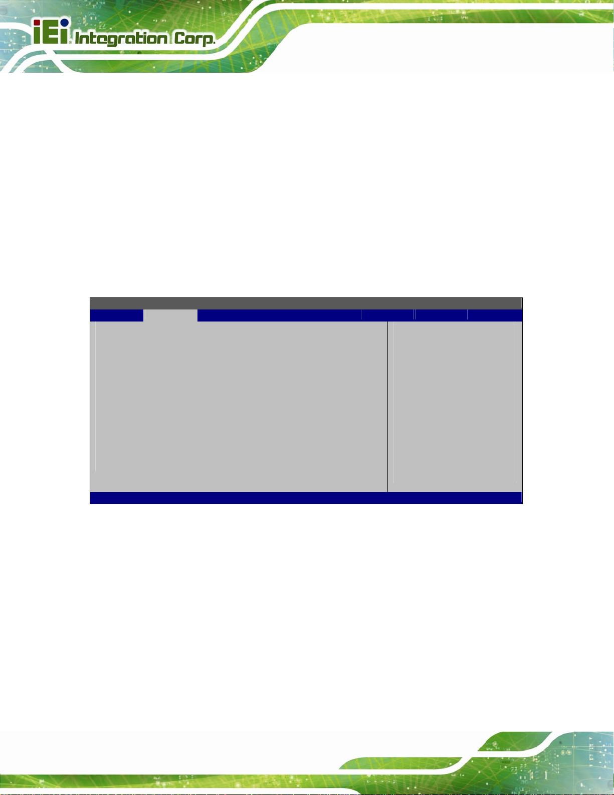
3.3 Advanced
Use the Advanced menu (BIOS Menu 2) to configure the CPU and peripheral devices
BIOS SETUP UTILITY
Main Advanced PCIPNP Boot Security Chipset Power Exit
Advanced Settings
⎯⎯⎯⎯⎯⎯⎯⎯⎯⎯⎯⎯⎯⎯⎯⎯⎯⎯⎯⎯⎯⎯⎯⎯⎯⎯⎯⎯⎯⎯⎯
WARNING: Setting wrong values in below sections may cause
system to malfunction
> CPU Configuration
> IDE Configuration
> SuperIO Configuration
> Hardware Health Configuration
> Power Configuration
> Remote Access Configuration
> USB Configuration
> iEi Feature
v02.61 ©Copyright 1985-2006, American Megatrends, Inc.
Configure CPU
Select Screen
↑ ↓ Select Item
Enter Go to SubScreen
F1 General Help
F10 Save and Exit
ESC Exit
BIOS Menu 2: Advanced
Page 45
Page 58
AFL2-W15A-N270 Panel PC
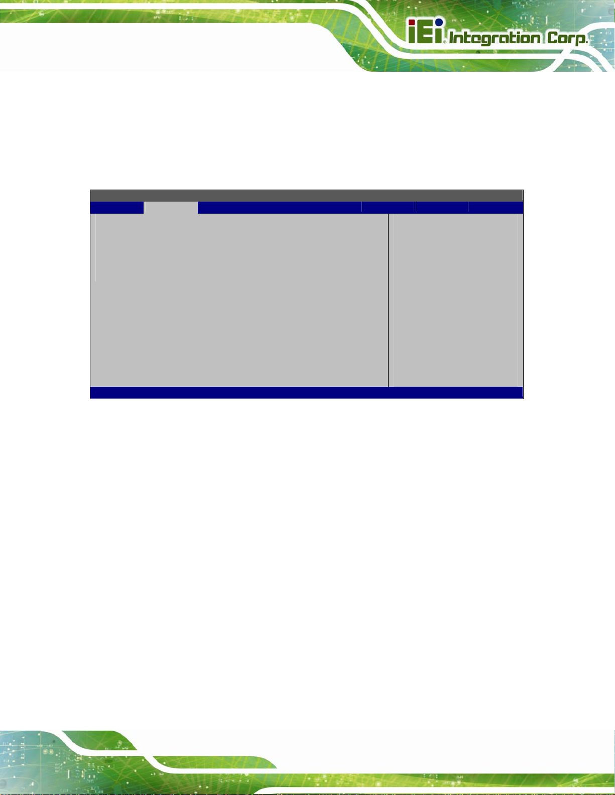
3.3.1 CPU Configuration
Use the CPU Configuration menu (BIOS Menu 3) to view detailed CPU specifications
and configure the CPU.
BIOS SETUP UTILITY
Main Advanced PCIPNP Boot Security Chipset Power Exit
Congifure advanced CPU settings
Module Version: 3F.10
⎯⎯⎯⎯⎯⎯⎯⎯⎯⎯⎯⎯⎯⎯⎯⎯⎯⎯⎯⎯⎯⎯⎯⎯⎯⎯⎯⎯⎯⎯⎯
Manufacturer :Intel
Genuine Intel(R) CPU N270 @ 1.60GHz
Frequency :1.60GHz
FSB Speed :533MHz
Cache L1 : 24KB
Cache L2 : 512KB
Ratio Actual Value:12
Hyper Threading Technology [Enabled]
v02.61 ©Copyright 1985-2006, American Megatrends, Inc.
Options
Disabled
Enabled
Select Screen
↑ ↓ Select Item
Enter Go to SubScreen
F1 General Help
F10 Save and Exit
ESC Exit
BIOS Menu 3: CPU Configuration
The CPU Configuration menu lists the following CPU details:
Manufacturer: Lists the name of the CPU manufacturer
Frequency: Lists the CPU processing speed
FSB Speed: Lists the FSB speed
Cache L1: Lists the CPU L1 cache size
Cache L2: Lists the CPU L2 cache size
Hyper Threading Technology [Enabled]
Use the Hyper Threading Technology to enable or disable the CPU hyper threading
function.
Disabled
Enabled DEFAULT
Disables the use of hyper threading technology
Enables the use of hyper threading technology
Page 46
Page 59

AFL2-W15A-N270 Panel PC
3.3.2 IDE Configuration
Use the IDE Configuration menu (BIOS Menu 4) to change and/or set the configuration
of the IDE devices installed in the system.
BIOS SETUP UTILITY
Main Advanced PCIPNP Boot Security Chipset Power Exit
IDE Configuration
⎯⎯⎯⎯⎯⎯⎯⎯⎯⎯⎯⎯⎯⎯⎯⎯⎯⎯⎯⎯⎯⎯⎯⎯⎯⎯⎯⎯⎯⎯⎯
ATA/IDE Configuration [Compatible]
Legacy IDE Channels [SATA Pri, PATA Sec]
> Primary IDE Master : [Not Detected]
> Primary IDE Slave : [Not Detected]
> Secondary IDE Master : [Not Detected]
> Secondary IDE Slave : [Not Detected]
Options
Disabled
Compatible
Enhanced
Select Screen
↑ ↓ Select Item
Enter Go to SubScreen
F1 General Help
F10 Save and Exit
ESC Exit
v02.61 ©Copyright 1985-2006, American Megatrends, Inc.
BIOS Menu 4: IDE Configuration
ATA/IDE Configurations [Compatible]
Use the ATA/IDE Configurations option to configure the ATA/IDE controller.
Disabled
Compatible DEFAULT
Enhanced
Disables the on-board ATA/IDE controller.
Configures the on-board ATA/IDE controller to be in
compatible mode. In this mode, a SATA channel will
replace one of the IDE channels. This mode supports
up to 4 storage devices.
Configures the on-board ATA/IDE controller to be in
Enhanced mode. In this mode, IDE channels and SATA
channels are separated. This mode supports up to 6
storage devices. Some legacy OS do not support this
mode.
Page 47
Page 60
Legacy IDE Channels [SATA Pri, PATA Sec]
AFL2-W15A-N270 Panel PC
SA TA Only
SA TA Pri, PATA Sec DEFAULT
PATA Only
Only the SATA drives are enabled.
The IDE drives are enabled on the SATA
channel. The IDE drives are enabled on the
Secondary IDE channel.
Only the IDE drives are enabled.
3.3.2.1 IDE Master, IDE Slave
Use the IDE Master and IDE Slave configuration menu to view both primary and
secondary IDE device details and configure the IDE devices connected to the system.
BIOS SETUP UTILITY
Main Advanced PCIPNP Boot Security Chipset Power Exit
Primary IDE Master
⎯⎯⎯⎯⎯⎯⎯⎯⎯⎯⎯⎯⎯⎯⎯⎯⎯⎯⎯⎯⎯⎯⎯⎯⎯⎯⎯⎯⎯⎯⎯
Device :Not Detected
⎯⎯⎯⎯⎯⎯⎯⎯⎯⎯⎯⎯⎯⎯⎯⎯⎯⎯⎯⎯⎯⎯⎯⎯⎯⎯⎯⎯⎯⎯⎯
Type [Auto]
LBA/Large Mode [Auto]
Block (Multi-Sector Transfer) [Auto]
PIO Mode [Auto]
DMA Mode [Auto]
S.M.A.R.T. [Auto]
32Bit Data Transfer [Enabled]
Select the type
of device connected
to the system
Select Screen
↑ ↓ Select Item
+- Change Option
F1 General Help
F10 Save and Exit
ESC Exit
v02.61 ©Copyright 1985-2006, American Megatrends, Inc.
BIOS Menu 5: IDE Master and IDE Slave Configuration
Auto-Detected Drive Parameters
The “grayed-out” items in the left frame are IDE disk drive parameters automatically
detected from the firmware of the selected IDE disk drive. The drive parameters are listed
as follows:
Device: Lists the device type (e.g. hard disk, CD-ROM etc.)
Type: Indicates the type of devices a user can manually select
Vendor: Lists the device manufacturer
Size: List the storage capacity of the device.
Page 48
Page 61

AFL2-W15A-N270 Panel PC
LBA Mode: Indicates whether the LBA (Logical Block Addressing) is a method
of addressing data on a disk drive is supported or not.
Block Mode: Block mode boosts IDE drive performance by increasing the
amount of data transferred. Only 512 bytes of data can be transferred per
interrupt if block mode is not used. Block mode allows transfers of up to 64 KB
per interrupt.
PIO Mode: Indicates the PIO mode of the installed device.
Async DMA: Indicates the highest Asynchronous DMA Mode that is
supported.
Ultra DMA: Indicates the highest Synchronous DMA Mode that is supported.
S.M.A.R.T.: Indicates whether or not the Self-Monitoring Analysis and
Reporting Technology protocol is supported.
32Bit Data Transfer: Enables 32-bit data transfer.
Type [Auto]
Use the Type BIOS option select the type of device the AMIBIOS attempts to boot from
after the Power-On Self-Test (POST) is complete.
Not Installed
Auto DEFAULT
CD/DVD
ARMD
BIOS is prevented from searching for an IDE disk
drive on the specified channel.
The BIOS auto detects the IDE disk drive type
attached to the specified channel. This setting should
be used if an IDE hard disk drive is attached to the
specified channel.
The CD/DVD option specifies that an IDE CD-ROM
drive is attached to the specified IDE channel. The
BIOS does not attempt to search for other types of
IDE disk drives on the specified channel.
This option specifies an ATAPI Removable Media
Device. These include, but are not limited to:
ZIP
LS-120
Page 49
Page 62

LBA/Large Mode [Auto]
Use the LBA/Large Mode option to disable or enable BIOS to auto detects LBA (Logical
Block Addressing). LBA is a method of addressing data on a disk drive. In LBA mode, the
maximum drive capacity is 137 GB.
AFL2-W15A-N270 Panel PC
Disabled
Auto DEFAULT
Block (Multi Sector Transfer) [Auto]
Use the Block (Multi Sector Transfer) to disable or enable BIOS to auto detect if the
device supports multi-sector transfers.
Disabled
Auto DEFAULT
BIOS is prevented from using the LBA mode control on
the specified channel.
BIOS auto detects the LBA mode control on the specified
channel.
BIOS is prevented from using Multi-Sector Transfer on the
specified channel. The data to and from the device occurs
one sector at a time.
BIOS auto detects Multi-Sector Transfer support on the
drive on the specified channel. If supported the data
transfer to and from the device occurs multiple sectors at
a time.
PIO Mode [Auto]
Use the PIO Mode option to select the IDE PIO (Programmable I/O) mode program timing
cycles between the IDE drive and the programmable IDE controller. As the PIO mode
increases, the cycle time decreases.
Auto DEFAULT
0
1
2
Page 50
BIOS auto detects the PIO mode. Use this value if the IDE disk
drive support cannot be determined.
PIO mode 0 selected with a maximum transfer rate of 3.3 MB/s
PIO mode 1 selected with a maximum transfer rate of 5.2 MB/s
PIO mode 2 selected with a maximum transfer rate of 8.3 MB/s
Page 63

AFL2-W15A-N270 Panel PC
3
4
DMA Mode [Auto]
Use the DMA Mode BIOS selection to adjust the DMA mode options.
Auto DEFAULT
S.M.A.R.T [Auto]
Use the S.M.A.R.T option to auto-detect, disable or enable Self-Monitoring Analysis and
Reporting Technology (SMART) on the drive on the specified channel. S.M.A.R.T predicts
PIO mode 3 selected with a maximum transfer rate of 11.1 MB/s
PIO mode 4 selected with a maximum transfer rate of 16.6 MB/s
(This setting generally works with all hard disk drives
manufactured after 1999. For other disk drives, such as IDE
CD-ROM drives, check the specifications of the drive.)
BIOS auto detects the DMA mode. Use this value if the IDE
disk drive support cannot be determined.
impending drive failures. The S.M.A.R.T BIOS option enables or disables this function.
Auto DEFAULT
Disabled
Enabled
32Bit Data Transfer [Enabled]
Use the 32Bit Data Transfer BIOS option to enables or disable 32-bit data transfers.
Disabled
Enabled DEFAULT
BIOS auto detects HDD SMART support.
Prevents BIOS from using the HDD SMART feature.
Allows BIOS to use the HDD SMART feature
Prevents the BIOS from using 32-bit data transfers.
Allows BIOS to use 32-bit data transfers on supported
hard disk drives.
Page 51
Page 64

AFL2-W15A-N270 Panel PC
3.3.3 Super IO Configuration
Use the Super IO Configuration menu (BIOS Menu 6) to set or change the
configurations for the FDD controllers, parallel ports and serial ports.
BIOS SETUP UTILITY
Main Advanced PCIPNP Boot Security Chipset Power Exit
Configure Super I/O Chipset
⎯⎯⎯⎯⎯⎯⎯⎯⎯⎯⎯⎯⎯⎯⎯⎯⎯⎯⎯⎯⎯⎯⎯⎯⎯⎯⎯⎯⎯⎯⎯
Serial Port1 Address [3F8/IRQ4]
Serial Port2 Address [2F8/IRQ3]
Serial Port3 Address [3E8]
Serial Port3 IRQ [10]
Select RS232/RS422 or RS485 [RS232/RS422]
Allows BIOS to select
Serial Port Base
Addresses
Select Screen
↑ ↓ Select Item
Enter Go to SubScreen
F1 General Help
F10 Save and Exit
ESC Exit
V02.61 ©Copyright 1985-2006, American Megatrends, Inc.
BIOS Menu 6: Super IO Configuration
Serial Port1 Address [3F8/IRQ4]
Selects the serial port base address.
Disabled
3F8/IRQ4 DEFAULT
3E8/IRQ4
2E8/IRQ3
Serial Port2 Address [2F8/IRQ3]
Selects the serial port base address.
Disabled
No base address
I/O address 3F8 and interrupt address IRQ4
I/O address 3E8 and interrupt address IRQ4
I/O address 2E8 and interrupt address IRQ3
No base address
Page 52
2F8/IRQ3 DEFAULT
3E8/IRQ4
I/O address 2F8 and interrupt address IRQ3
I/O address 3E8 and interrupt address IRQ4
Page 65

AFL2-W15A-N270 Panel PC
2E8/IRQ3
Serial Port3 Address [3E8]
Selects the serial port base address.
Disabled
3E8 DEFAULT
2D8
2D0
Serial Port3 IRQ [10]
Selects the serial port interrupt address.
10 DEFAULT
11
I/O address 2E8 and interrupt address IRQ3
No base address
I/O address 3E8
I/O address 2D8
I/O address 2D0
IRQ address 10
IRQ address 11
Page 53
Page 66

AFL2-W15A-N270 Panel PC
3.3.4 Hardware Health Configuration
The Hardware Health Configuration menu (BIOS Menu 7) shows the operating
temperature, fan speeds and system voltages.
BIOS SETUP UTILITY
Main Advanced PCIPNP Boot Security Chipset Power Exit
Hardware Health Configuration
⎯⎯⎯⎯⎯⎯⎯⎯⎯⎯⎯⎯⎯⎯⎯⎯⎯⎯⎯⎯⎯⎯⎯⎯⎯⎯⎯⎯⎯⎯⎯
CPU Temperature :66ºC/152ºF
System Temperature :51ºC/123ºF
CPU Core :1.152 V
+1.05V :1.040 V
+3.30V :3.408 V
+5.00V :5.214 V
+12.0V :12.032 V
+1.5V :1.488 V
+1.8V :1.792 V
5VSB :5.241 V
VBAT :3.312 V
v02.61 ©Copyright 1985-2006, American Megatrends, Inc.
Select Screen
↑ ↓ Select Item
Enter Go to SubScreen
F1 General Help
F10 Save and Exit
ESC Exit
BIOS Menu 7: Hardware Health Configuration
Monitored Values
The following system parameters and values are shown. The system parameters that are
monitored are:
The following system temperatures are monitored:
o CPU temperature
o System temperature
The following core voltages are monitored:
o CPU Core
o +1.05V
o +3.30V
o +5.00V
o +12.0V
o +1.5V
Page 54
o +1.8V
o 5VSB
Page 67
S
AFL2-W15A-N270 Panel PC
o VBAT
3.3.5 Power Configuration
The Power Configuration menu (BIOS Menu 8) allows the advanced power
management options to be configured.
BIOS SETUP UTILITY
Main Advanced PCIPNP Boot Security Chipset Power Exit
Power Supply Status [ATX]
> ACPI Configuration
> APM Configuration
V02.61 ©Copyright 1985-2006, American Megatrends, Inc.
elect for Advanced ACPI
Configuration
Select Screen
↑ ↓ Select Item
Enter Go to SubScreen
F1 General Help
F10 Save and Exit
ESC Exit
BIOS Menu 8: Power Configuration
Page 55
Page 68

AFL2-W15A-N270 Panel PC
3.3.5.1 ACPI Settings
Use the ACPI Settings menu (BIOS Menu 9) to select the ACPI state when the system is
suspended.
BIOS SETUP UTILITY
Main Advanced PCIPNP Boot Security Chipset Power Exit
ACPI Settings
⎯⎯⎯⎯⎯⎯⎯⎯⎯⎯⎯⎯⎯⎯⎯⎯⎯⎯⎯⎯⎯⎯⎯⎯⎯⎯⎯⎯⎯⎯⎯
Suspend Mode [S1 (POS)]
V02.61 ©Copyright 1985-2006, American Megatrends, Inc.
Select the ACPI state
used for System Suspend.
Select Screen
↑ ↓ Select Item
Enter Go to SubScreen
F1 General Help
F10 Save and Exit
ESC Exit
BIOS Menu 9: ACPI Settings
Suspend Mode [S1(POS)]
Use the Suspend Mode option to specify the sleep state the system enters when it is not
being used.
S1 (POS) DEFAULT
S3 (STR)
The system enters S1(POS) sleep state. The system
appears off. The CPU is stopped; RAM is refreshed; the
system is running in a low power mode.
The system enters S3(STR) sleep state.
Page 56
Page 69

AFL2-W15A-N270 Panel PC
3.3.5.2 APM Configuration
The APM Configuration menu (BIOS Menu 10) allows the advanced power
management options to be configured.
BIOS SETUP UTILITY
Main Advanced PCIPNP Boot Security Chipset Power Exit
APM Configuration
⎯⎯⎯⎯⎯⎯⎯⎯⎯⎯⎯⎯⎯⎯⎯⎯⎯⎯⎯⎯⎯⎯⎯⎯⎯⎯⎯⎯⎯⎯⎯
Restore on AC Power Loss [Last State]
Power Button Mode [On/Off]
Advanced Resume Event Controls
Resume On KeyBoard/Mouse [Disabled]
Resume On Touch Panel [Disabled]
Resume On Ring [Disabled]
Resume On LAN [Enabled]
Resume on RTC Alarm [Disabled]
If the AT/ATX jumper
been set to AT mode
this item will be
changed to "power on"
automatically
Select Screen
↑ ↓ Select Item
Enter Go to SubScreen
F1 General Help
F10 Save and Exit
ESC Exit
v02.61 ©Copyright 1985-2006, American Megatrends, Inc.
BIOS Menu 10: APM Configuration
Restore on AC Power Loss [Last State]
Use the Restore on AC Power Loss BIOS option to specify what state the system
returns to if there is a sudden loss of power to the system.
Power Off
Power On
Last State DEFAULT
Power Button Mode [On/Off]
Use the Power Button Mode BIOS to specify how the power button functions.
The system remains turned off
The system turns on
The system returns to its previous state. If it was on, it
turns itself on. If it was off, it remains off.
On/Off DEFAULT
When the power button is pressed the system is either
turned on or off
Page 57
Page 70

AFL2-W15A-N270 Panel PC
Suspend
Resume on Keyboard/Mouse [Disabled]
Use the Resume on Keyboard/Mouse BIOS option to enable activity on either the
keyboard or mouse to rouse the system from a suspend or standby state. That is, the
system is roused when the mouse is moved or a button on the keyboard is pressed.
Disabled DEFAULT
Resume On
KeyBoard
Resume On
Mouse
Enabled
Wake event generated by activity on the keyboard
Wake event generated by activity on the mouse
When the power button is pressed the system goes into
suspend mode
Wake event not generated by activity on the
keyboard or mouse
Wake event generated by activity on the keyboard or
mouse
Resume on Touch Panel [Disabled]
Use the Resume Touch Panel BIOS option to enable activity on the touch panel to rouse
the system from a suspend or standby state. That is, the system will be roused by
touching the touch panel.
Disabled DEFAULT
Enabled
Resume on Ring [Disabled]
Use the Resume on Ring BIOS option to enable activity on the RI (ring in) modem line to
rouse the system from a suspend or standby state. That is, the system will be roused by
an incoming call on a modem.
Disabled DEFAULT
Wake event not generated by touch panel activity
Wake event generated by touch panel activity
Wake event not generated by an incoming call
Page 58
Enabled
Wake event generated by an incoming call
Page 71

AFL2-W15A-N270 Panel PC
Resume on LAN [Enabled]
The Resume on LAN BIOS option specifies if the system is roused from a suspended or
standby state when there is activity on the LAN.
Enabled DEFAULT
Disabled
Resume On RT C Alarm [Disabled]
Use the Resume On RTC Alarm option to specify the time the system should be roused
from a suspended state.
Disabled DEFAULT
Enabled
Wake event generated by LAN activity
Wake event not generated by LAN activity
The real time clock (RTC) cannot generate a wake
event
If selected, the following appears with values that
can be selected:
RTC Alarm Date (Days)
RTC Alarm Time
After setting the alarm, the computer turns itself on
from a suspend state when the alarm goes off.
3.3.6 Remote Access Configuration
Use the Remote Access Configuration menu (BIOS Menu 11) to configure remote
access parameters. The Remote Access Configuration is an AMIBIOS feature and
allows a remote host running a terminal program to display and configure the BIOS
settings.
Page 59
Page 72

BIOS SETUP UTILITY
Main Advanced PCIPNP Boot Security Chipset Power Exit
Configure Remote Access type and parameters
⎯⎯⎯⎯⎯⎯⎯⎯⎯⎯⎯⎯⎯⎯⎯⎯⎯⎯⎯⎯⎯⎯⎯⎯⎯⎯⎯⎯⎯⎯⎯
Remote Access [Disabled]
v02.61 ©Copyright 1985-2006, American Megatrends, Inc.
BIOS Menu 11: Remote Access Configuration
Remote Access [Disabled]
AFL2-W15A-N270 Panel PC
Select Screen
↑ ↓ Select Item
Enter Go to SubScreen
F1 General Help
F10 Save and Exit
ESC Exit
Use the Remote Access option to enable or disable access to the remote functionalities
of the system.
Disabled DEFAULT
Enabled
Serial Port Number [COM1]
Use the Serial Port Number option allows to select the serial port used for remote
access.
Remote access is disabled.
Remote access configuration options shown below
appear:
Serial Port Number
Serial Port Mode
Redirection after BIOS POST
Terminal Type
These configuration options are discussed below.
Page 60
COM1 DEFAULT
COM3
System is remotely accessed through COM1
System is remotely accessed through COM3
Page 73

AFL2-W15A-N270 Panel PC
NOTE: Make sure the selected COM port is enabled through the Super I/O configuration
menu.
Base Address, IRQ [3F8h, 4]
The Base Address, IRQ option cannot be configured and only shows the interrupt
address of the serial port listed above.
Serial Port Mode [115200 8,n,1]
Use the Serial Port Mode option to select baud rate through which the console redirection
is made. The following configuration options are available
115200 8,n,1 D
57600 8,n,1
38400 8,n,1
19200 8,n,1
09600 8,n,1
EFAULT
NOTE:
Identical baud rate setting musts be set on the host (a management
computer running a terminal software) and the slave
Redirection After BIOS POST [Always]
Use the Redirection After BIOS POST option to specify when console redirection should
occur.
Disabled
The console is not redirected after POST
Boot Loader
Always DEFAULT
Redirection is active during POST and during Boot
Loader
Redirection is always active (Some OSes may not
work if set to Always)
Page 61
Page 74

Terminal Type [ANSI]
Use the Terminal Type BIOS option to specify the remote terminal type.
AFL2-W15A-N270 Panel PC
ANSI DEFAULT
VT100
VT-UTF8
The target terminal type is ANSI
The target terminal type is VT100
The target terminal type is VT-UTF8
3.3.7 USB Configuration
Use the USB Configuration menu (BIOS Menu 12) to read USB configuration
information and configure the USB settings.
BIOS SETUP UTILITY
Main Advanced PCIPNP Boot Security Chipset Power Exit
USB Configuration
⎯⎯⎯⎯⎯⎯⎯⎯⎯⎯⎯⎯⎯⎯⎯⎯⎯⎯⎯⎯⎯⎯⎯⎯⎯⎯⎯⎯⎯⎯⎯
Module Version – 2.24.5-13.4
USB Devices Enabled:
1 Keyboard, 1 Mouse
USB Functions [Enabled]
USB 2.0 Controller [Enabled]
Legacy USB Support [Enabled]
USB 2.0 Controller Mode [HiSpeed]
Options
Disabled
Enabled
Select Screen
↑ ↓ Select Item
Enter Go to SubScreen
F1 General Help
F10 Save and Exit
ESC Exit
V02.61 ©Copyright 1985-2006, American Megatrends, Inc.
BIOS Menu 12: USB Configuration
USB Configuration
The USB Configuration field shows the system USB configuration. The items listed are:
Module Version: x.xxxxx.xxxxx
USB Devices Enabled
The USB Devices Enabled field lists the USB devices that are enabled on the system
Page 62
Page 75

AFL2-W15A-N270 Panel PC
USB Function [Enabled]
Use the USB Function BIOS option to enable or disable USB function support.
Disabled
Enabled DEFAULT
USB 2.0 Controller [Enabled]
Use the USB 2.0 Controller BIOS option to enable or disable the USB 2.0 controller
Enabled DEFAULT
Disabled
Legacy USB Support [Enabled]
Use the Legacy USB Support BIOS option to enable USB mouse and USB keyboard
support.
Normally if this option is not enabled, any attached USB mouse or USB keyboard does not
become available until a USB compatible operating system is fully booted with all USB
USB function support disabled
USB function support enabled
USB 2.0 controller enabled
USB 2.0 controller disabled
drivers loaded. When this option is enabled, any attached USB mouse or USB keyboard
can control the system even when there is no USB driver loaded onto the system.
Disabled
Enabled DEFAULT
Auto
USB2.0 Controller Mode [HiSpeed]
Use the USB2.0 Controller Mode option to set the speed of the USB2.0 controller.
FullSpeed
HiSpeed DEFAULT
Legacy USB support disabled
Legacy USB support enabled
Legacy USB support disabled if no USB devices are
connected
The controller is capable of operating at 12 Mb/s
The controller is capable of operating at 480 Mb/s
Page 63
Page 76

AFL2-W15A-N270 Panel PC
3.3.8 IEI Feature
Use the IEI Feature menu (BIOS Menu 13) to configure One Key Recovery function.
BIOS SETUP UTILITY
Main Advanced PCIPNP Boot Security Chipset Exit
iEi Feature
⎯⎯⎯⎯⎯⎯⎯⎯⎯⎯⎯⎯⎯⎯⎯⎯⎯⎯⎯⎯⎯⎯⎯⎯⎯⎯⎯⎯⎯⎯⎯
Auto Recovery Function [Disabled]
v02.61 ©Copyright 1985-2006, American Megatrends, Inc.
Auto Recovery Function
Reboot and recover
system automatically
within 10 min, when OS
crashed.
Please install Auto
Recovery API service
before enabling this
function
Select Screen
↑ ↓ Select Item
Enter Go to SubScreen
F1 General Help
F10 Save and Exit
ESC Exit
BIOS Menu 13: IEI Feature
Auto Recovery Function [Disabled]
Use the Auto Recovery Function BIOS option to enable or disable the auto recovery
function of the IEI One Key Recovery.
Disabled DEFAULT
Enabled
Auto recovery function disabled
Auto recovery function enabled
Page 64
Page 77
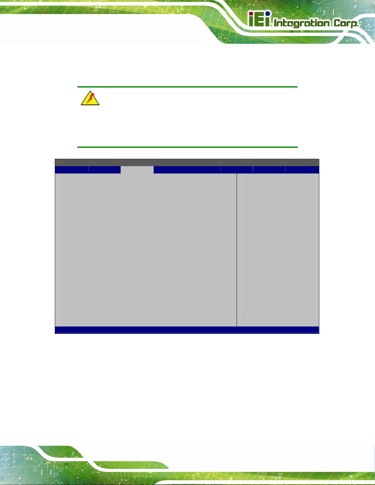
A
R
AFL2-W15A-N270 Panel PC
3.4 PCI/PnP
Use the PCI/PnP menu (BIOS Menu 14) to configure advanced PCI and PnP settings.
WARNING!
Setting wrong values for the BIOS selections in the PCIPnP BIOS
menu may cause the system to malfunction.
BIOS SETUP UTILITY
Main Advanced PCIPNP Boot Security Chipset Power Exit
Advanced PCI/PnP Settings
⎯⎯⎯⎯⎯⎯⎯⎯⎯⎯⎯⎯⎯⎯⎯⎯⎯⎯⎯⎯⎯⎯⎯⎯⎯⎯⎯⎯⎯⎯⎯
IRQ3 [Reserved]
IRQ4 [Reserved]
IRQ5 [Available]
IRQ7 [Available]
IRQ9 [Available]
IRQ10 [Reserved]
IRQ11 [Reserved]
IRQ14 [Available]
IRQ15 [Available]
DMA Channel 0 [Available]
DMA Channel 1 [Available]
DMA Channel 3 [Available]
DMA Channel 5 [Available]
DMA Channel 6 [Available]
DMA Channel 7 [Available]
Reserved Memory Size [Disabled]
v02.61 ©Copyright 1985-2006, American Megatrends, Inc.
vailable: Specified IRQ
is available to be use
the PCI/PnP devices
eserved: Specified IRQ
is reserved for use by
legacy ISA devices
Select Screen
↑ ↓ Select Item
Enter Go to SubScreen
F1 General Help
F10 Save and Exit
ESC Exit
BIOS Menu 14: PCI/PnP Configuration
IRQ# [Available]
Use the IRQ# address to specify what IRQs can be assigned to a particular peripheral
device.
Available DEFAULT
The specified IRQ is available to be used by
PCI/PnP devices
Page 65
Page 78

AFL2-W15A-N270 Panel PC
Reserved
Available IRQ addresses are:
IRQ3
IRQ4
IRQ5
IRQ7
IRQ9
IRQ10
IRQ 11
IRQ 14
IRQ 15
DMA Channel# [Available]
Use the DMA Channel# option to assign a specific DMA channel to a particular PCI/PnP
The specified IRQ is reserved for use by Legacy ISA
devices
device.
Available DEFAULT
Reserved
Available DMA Channels are:
DM Channel 0
DM Channel 1
DM Channel 3
DM Channel 5
DM Channel 6
DM Channel 7
The specified DMA is available to be used by
PCI/PnP devices
The specified DMA is reserved for use by Legacy
ISA devices
Page 66
Page 79
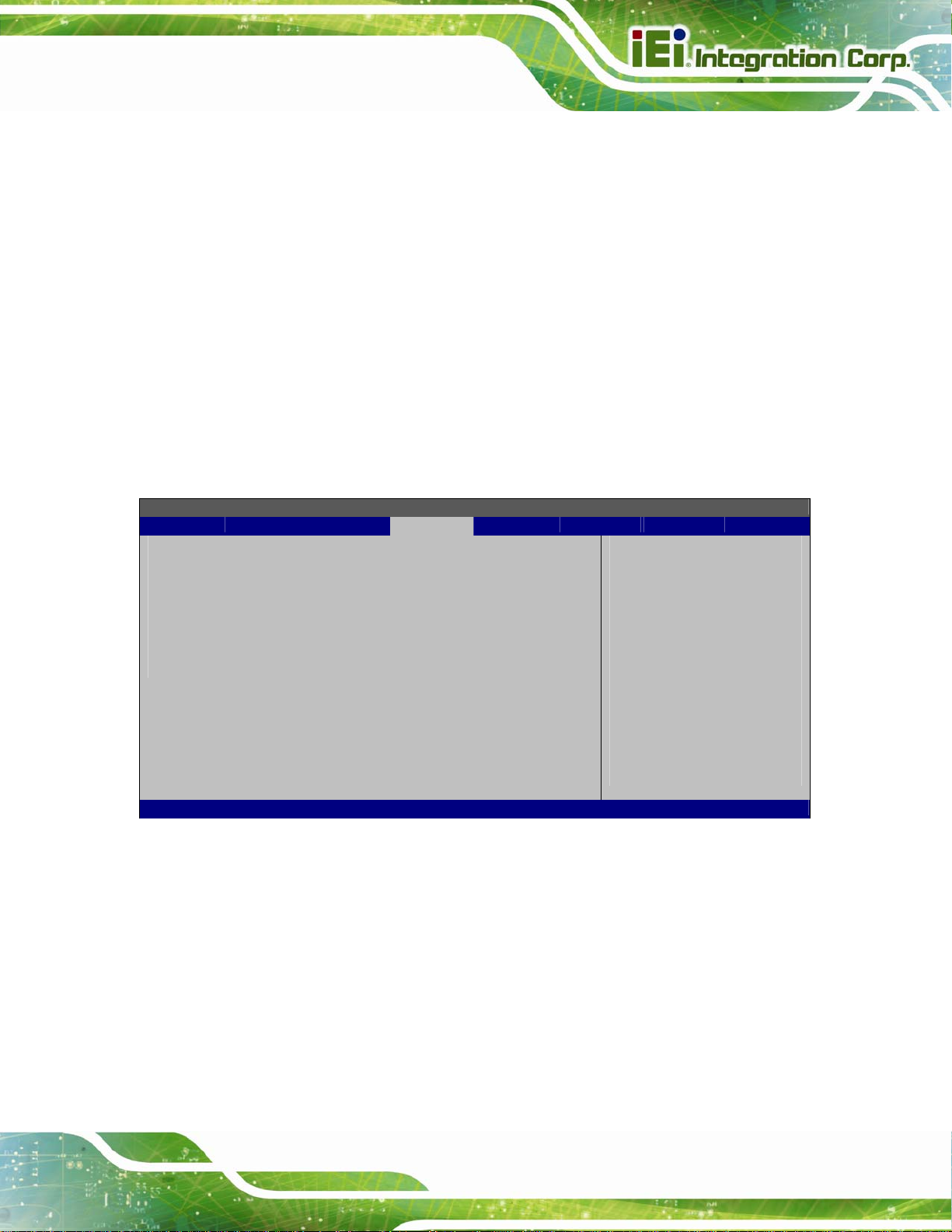
AFL2-W15A-N270 Panel PC
Reserved Memory Size [Disabled]
Use the Reserved Memory Size BIOS option to specify the amount of memory that
should be reserved for legacy ISA devices.
Disabled DEFAULT
16K
32K
64K
No memory block reserved for legacy ISA devices
16 KB reserved for legacy ISA devices
32 KB reserved for legacy ISA devices
54 KB reserved for legacy ISA devices
3.5 Boot
Use the Boot menu (BIOS Menu 15) to configure system boot options.
BIOS SETUP UTILITY
Main Advanced PCIPNP Boot Security Chipset Power Exit
Boot Settings
⎯⎯⎯⎯⎯⎯⎯⎯⎯⎯⎯⎯⎯⎯⎯⎯⎯⎯⎯⎯⎯⎯⎯⎯⎯⎯⎯⎯⎯⎯⎯
> Boot Settings Configuration
> Boot Device Priority
> Hard Disk Drives
Configure settings
during system boot.
Select Screen
↑ ↓ Select Item
Enter Go to SubScreen
F1 General Help
F10 Save and Exit
ESC Exit
v02.61 ©Copyright 1985-2006, American Megatrends, Inc.
BIOS Menu 15: Boot
Page 67
Page 80

AFL2-W15A-N270 Panel PC
3.5.1 Boot Settings Configuration
Use the Boot Settings Configuration menu (BIOS Menu 16) to configure advanced
system boot options.
BIOS SETUP UTILITY
Main Advanced PCIPNP Boot Security Chipset Power Exit
Boot Settings Configuration
⎯⎯⎯⎯⎯⎯⎯⎯⎯⎯⎯⎯⎯⎯⎯⎯⎯⎯⎯⎯⎯⎯⎯⎯⎯⎯⎯⎯⎯⎯⎯
Quick Boot [Enabled]
Quiet Boot [Enabled]
AddOn ROM Display Mode [Force BIOS]
Bootup Num-Lock [On]
Boot From LAN Support [Disabled]
Spread Spectrum Function [Disabled]
Allows BIOS to skip
certain tests while
booting. This will
decrease the time
needed to boot the
system.
Select Screen
↑ ↓ Select Item
Enter Go to SubScreen
F1 General Help
F10 Save and Exit
ESC Exit
v02.61 ©Copyright 1985-2006, American Megatrends, Inc.
BIOS Menu 16: Boot Settings Configuration
Quick Boot [Enabled]
Use the Quick Boot BIOS option to make the computer speed up the boot process.
Disabled
Enabled DEFAULT
Quiet Boot [Enabled]
Use the Quiet Boot BIOS option to select the screen display when the system boots.
Disabled DEFAULT
Enabled
No POST procedures are skipped
Some POST procedures are skipped to decrease
the system boot time
Normal POST messages displayed
OEM Logo displayed instead of POST messages
Page 68
Page 81

AFL2-W15A-N270 Panel PC
AddOn ROM Display Mode [Force BIOS]
Use the AddOn ROM Display Mode option to allow add-on ROM (read-only memory)
messages to be displayed.
Force BIOS DEFAULT
Keep Current
Bootup Num-Lock [On]
Use the Bootup Num-Lock BIOS option to specify if the number lock setting must be
modified during boot up.
Off
On DEFAULT
Does not enable the keyboard Number Lock automatically. To
use the 10-keys on the keyboard, press the Number Lock key
located on the upper left-hand corner of the 10-key pad. The
Number Lock LED on the keyboard lights up when the Number
Lock is engaged.
Allows the Number Lock on the keyboard to be enabled
automatically when the computer system boots up. This allows
The system forces third party BIOS to display
during system boot.
The system displays normal information during
system boot.
the immediate use of the 10-key numeric keypad located on
the right side of the keyboard. To confirm this, the Number
Lock LED light on the keyboard is lit.
Boot From LAN Support [Dis abled]
Use the BOOT From LAN Support option to enable the system to be booted from a
remote system.
Enabled
Disabled DEFAULT
Can be booted from a remote system through the
LAN
Cannot be booted from a remote system through the
LAN
Page 69
Page 82

Spread Spectrum Mode [Disabled]
The Spread Spectrum Mode option can help to improve CPU EMI issues.
AFL2-W15A-N270 Panel PC
Disabled DEFAULT
Enabled
The spread spectrum mode is disabled
The spread spectrum mode is enabled
3.5.2 Boot Device Priority
Use the Boot Device Priority menu (BIOS Menu 17) to specify the boot sequence from
the available devices. The drive sequence also depends on the boot sequence in the
individual device section.
BIOS SETUP UTILITY
Main Advanced PCIPNP Boot Security Chipset Power Exit
Boot Device Priority
⎯⎯⎯⎯⎯⎯⎯⎯⎯⎯⎯⎯⎯⎯⎯⎯⎯⎯⎯⎯⎯⎯⎯⎯⎯⎯⎯⎯⎯⎯⎯
> 1st Boot Device [1st Boot Device]
Specifies the boot
sequence from the
available devices.
Select Screen
↑ ↓ Select Item
Enter Go to SubScreen
F1 General Help
F10 Save and Exit
ESC Exit
Page 70
v02.61 ©Copyright 1985-2006, American Megatrends, Inc.
BIOS Menu 17: Boot Device Priority Settings
Page 83

AFL2-W15A-N270 Panel PC
3.5.3 Hard Disk Drives
Use the Hard Disk Drives menu to specify the boot sequence of the available HDDs.
Only installed hard drives are shown.
BIOS SETUP UTILITY
Main Advanced PCIPNP Boot Security Chipset Power Exit
Hard Disk Drives
⎯⎯⎯⎯⎯⎯⎯⎯⎯⎯⎯⎯⎯⎯⎯⎯⎯⎯⎯⎯⎯⎯⎯⎯⎯⎯⎯⎯⎯⎯⎯
> 1st Drive [Hard Drive 1]
Specifies the boot
sequence from the
available devices.
Select Screen
↑ ↓ Select Item
Enter Go to SubScreen
F1 General Help
F10 Save and Exit
ESC Exit
v02.61 ©Copyright 1985-2006, American Megatrends, Inc.
BIOS Menu 18: Hard Disk Drives
3.6 Security
Use the Security menu (BIOS Menu 19) to set system and user passwords.
BIOS SETUP UTILITY
Main Advanced PCIPNP Boot Security Chipset Power Exit
Security Settings
⎯⎯⎯⎯⎯⎯⎯⎯⎯⎯⎯⎯⎯⎯⎯⎯⎯⎯⎯⎯⎯⎯⎯⎯⎯⎯⎯⎯⎯⎯⎯
Supervisor Password :Not Installed
User Password :Not Installed
Change Supervisor Password
Change User Password
v02.61 ©Copyright 1985-2006, American Megatrends, Inc.
Install or Change the
password.
Select Screen
↑ ↓ Select Item
Enter Go to SubScreen
F1 General Help
F10 Save and Exit
ESC Exit
BIOS Menu 19: Security
Page 71
Page 84

Change Superv isor Password
Use the Change Supervisor Password to set or change a supervisor password. The
default for this option is Not Installed. If a supervisor password must be installed, select
this field and enter the password. After the password has been added, Install appears
next to Change Supervisor Password.
Change User Password
Use the Change User Password to set or change a user password. The default for this
option is Not Installed. If a user password must be installed, select this field and enter the
password. After the password has been added, Install appears next to Change User
Password.
3.7 Advanced Chipset Settings
AFL2-W15A-N270 Panel PC
Use the Advanced Chipset Settings menu (BIOS Menu 20) to access the Northbridge
and Southbridge configuration menus
WARNING!
Setting the wrong values for the Chipset BIOS selections in the Chipset
BIOS menu may cause the system to malfunction.
Page 72
Page 85

AFL2-W15A-N270 Panel PC
BIOS SETUP UTILITY
Main Advanced PCIPNP Boot Security Chipset Power Exit
Advanced Chipset Settings
⎯⎯⎯⎯⎯⎯⎯⎯⎯⎯⎯⎯⎯⎯⎯⎯⎯⎯⎯⎯⎯⎯⎯⎯⎯⎯⎯⎯⎯⎯⎯
WARNING: Setting wrong values in below section
may cause system to malfunction.
> North Bridge Configuration
> South Bridge Configuration
v02.61 ©Copyright 1985-2006, American Megatrends, Inc.
BIOS Menu 20: Advanced Chipset Settings
Select Screen
↑ ↓ Select Item
Enter Go to SubScreen
F1 General Help
F10 Save and Exit
ESC Exit
3.7.1 North Bridge Configuration
Use the North Bridge Configuration menu (BIOS Menu 21) to configure the Northbridge
chipset.
BIOS SETUP UTILITY
Main Advanced PCIPNP Boot Security Chipset Power Exit
North Bridge Chipset Configuration
⎯⎯⎯⎯⎯⎯⎯⎯⎯⎯⎯⎯⎯⎯⎯⎯⎯⎯⎯⎯⎯⎯⎯⎯⎯⎯⎯⎯⎯⎯⎯
Memory Hole [Disabled]
Internal Graphics Mode Select [Enabled, 8MB]
Video Function Configuration
⎯⎯⎯⎯⎯⎯⎯⎯⎯⎯⎯⎯⎯⎯⎯⎯⎯⎯⎯⎯⎯⎯⎯⎯⎯⎯⎯⎯⎯⎯⎯
DVMT Mode Select [DVMT Mode]
DVMT/FIXED Memory [Maximum DVMT]
Boot Display Device [Auto]
LVDS2 Panel Type [by H/W]
LVDS2 Current Jumper Setting [1366x768 24b]
v02.61 ©Copyright 1985-2006, American Megatrends, Inc.
BIOS Menu 21: North Bridge Configuration
Select Screen
↑ ↓ Select Item
Enter Go to SubScreen
F1 General Help
F10 Save and Exit
ESC Exit
Page 73
Page 86

Memory Hole [Disabled]
Use the Memory Hole option to reserve memory space between 15 MB and 16 MB for
ISA expansion cards that require a specified area of memory to work properly. If an older
ISA expansion card is used, please refer to the documentation that came with the card to
see if it is necessary to reserve the space.
AFL2-W15A-N270 Panel PC
Disabled DEFAULT
15 MB–16 MB
Internal Graphics Mode Select [En able, 8 MB]
Use the Internal Graphic Mode Select option to specify the amount of system memory
that can be used by the Internal graphics device.
Disable
Enable, 1 MB
Enable, 8 MB DEFAULT
DVMT Mode Select [DVMT Mode]
Use the DVMT Mode Select option to select the Intel Dynamic Video Memory Technology
(DVMT) operating mode.
Memory is not reserved for ISA expansion cards
Between 15 MB and 16 MB of memory is reserved
for ISA expansion cards
1 MB of memory used by internal graphics device
8 MB of memory used by internal graphics device
Page 74
Fixed Mode
DVMT Mode DEFAULT
Combo
Mode
A fixed portion of graphics memory is reserved as
graphics memory.
Graphics memory is dynamically allocated according to
the system and graphics needs.
A fixed portion of graphics memory is reserved as
graphics memory. If more memory is needed, graphics
memory is dynamically allocated according to the
system and graphics needs.
Page 87

AFL2-W15A-N270 Panel PC
DVMT/FIXED Memory [Maximum DVMT]
Use the DVMT/FIXED Memory option to specify the maximum amount of memory that
can be allocated as graphics memory. Configuration options are listed below.
64MB
128MB
Maximum DVMT Default
Boot Display Device [Auto]
Use the Boot Display Device option to select the display device used by the system
when it boots. Configuration options are listed below.
Auto Default
CRT
LVDS
LVDS Panel Type [by H/W]
Use the LVDS Panel Type option to select the type of flat panel connected to the system.
Configuration options are listed below.
1440x900 48b
1024x768 24b
1366x768 24b
1280x1024 48b
By H/W D
EFAULT
3.7.2 South Bridge Configuration
Use the South Bbridge Configuration menu (BIOS Menu 22) to configure the
Southbridge chipset.
Page 75
Page 88

BIOS SETUP UTILITY
Main Advanced PCIPNP Boot Security Chipset Power Exit
South Bridge Chipset Configuration
⎯⎯⎯⎯⎯⎯⎯⎯⎯⎯⎯⎯⎯⎯⎯⎯⎯⎯⎯⎯⎯⎯⎯⎯⎯⎯⎯⎯⎯⎯⎯
Audio Controller [Auto]
Spread Spectrum Clock [Disabled]
v02.61 ©Copyright 1985-2006, American Megatrends, Inc.
BIOS Menu 22:South Bridge Configuration
AFL2-W15A-N270 Panel PC
Options
Auto
Azalia
AC'97 Audio Only
All Disabled
Select Screen
↑ ↓ Select Item
Enter Go to SubScreen
F1 General Help
F10 Save and Exit
ESC Exit
Audio Controller [Auto]
Use the Audio Controller option to enable or disable audio controller.
Auto DEFAULT
All Disabled
Spread Spectrum Clock [Disabled]
The Spread Spectrum Clock option can help to improve CPU EMI issues.
Disabled DEFAULT
Enabled
The spread spectrum clock is disabled
The spread spectrum clock is enabled
Enabled audio controller automatically
The on-board audio controller is disabled.
Page 76
Page 89

E
F
AFL2-W15A-N270 Panel PC
3.8 Exit
Use the Exit menu (BIOS Menu 23) to load default BIOS values, optimal failsafe values
and to save configuration changes.
BIOS SETUP UTILITY
Main Advanced PCIPNP Boot Security Chipset Power Exit
Exit Options
⎯⎯⎯⎯⎯⎯⎯⎯⎯⎯⎯⎯⎯⎯⎯⎯⎯⎯⎯⎯⎯⎯⎯⎯⎯⎯⎯⎯⎯⎯⎯
Save Changes and Exit
Discard Changes and Exit
Discard Changes
Load Optimal Defaults
Load Failsafe Defaults
xit system setup after
saving the changes.
10 key can be used for
this operation
Select Screen
↑ ↓ Select Item
Enter Go to SubScreen
F1 General Help
F10 Save and Exit
ESC Exit
v02.61 ©Copyright 1985-2006, American Megatrends, Inc.
BIOS Menu 23:Exit
Save Changes and Exit
Use the Save Changes and Exit option to save the changes made to the BIOS options
and to exit the BIOS configuration setup program.
Discard Changes and Exit
Use the Discard Changes and Exit option to exit the BIOS configuration setup program
without saving the changes made to the system.
Discard Changes
Use the Discard Changes option to discard the changes and remain in the BIOS
configuration setup program.
Load Optimal Defaults
Use the Load Optimal Defaults option to load the optimal default values for each of the
parameters on the Setup menus. F9 key can be used for this operation.
Page 77
Page 90

Load Failsafe Defaults
Use the Load Failsafe Defaults option to load failsafe default values for each of the
parameters on the Setup menus. F8 key can be used for this operation.
AFL2-W15A-N270 Panel PC
Page 78
Page 91

AFL2-W15A-N270 Panel PC
4 System Maintenance
Chapter
4
Page 79
Page 92

4.1 System Maintenance Introduction
If the components of the AFL2-W15A-N270 fail they must be replaced, such as the
wireless LAN module or the motherboard. Please contact the system reseller or vendor to
purchase the replacement parts. Memory module replacement instruction for the
AFL2-W15A-N270 is described below.
4.2 Motherboard Replacement
In the case of motherboard failure, please contact an IEI sales representative, reseller or
system vendor. The motherboard is accessible after opening the rear cover.
4.3 Memory Module Replacement
The flat panel PC has a preinstalled memory module. If the memory module fails, take the
steps below to replace it.
AFL2-W15A-N270 Panel PC
Step 1: Remove the back cover. See Section
Step 2: Locate the memory module on the motherboard of the flat panel PC
Step 3: Remove the memory module by pulling both the spring retainer clips outward
from the socket.
Step 4: Grasp the memory module by the edges and carefully pull it out of the socket.
Step 5: Install the new memory module by inserting it at an angle, then pushing down
until the clips snap into place (
Figure 4-1).Step 0:
2.6.
Page 80
Figure 4-1: SO-DIMM Module Installation
Page 93

AFL2-W15A-N270 Panel PC
A Safety Precautions
Appendix
A
Page 81
Page 94

WARNING:
The precautions outlined in this chapter should be strictly followed.
Failure to follow these precautions may result in permanent damage to
the AFL2-W15A-N270.
A.1 Safety Precautions
Please follow the safety precautions outlined in the sections that follow:
A.1.1 General Safety Precautions
Please ensure the following safety precautions are adhered to at all times.
AFL2-W15A-N270 Panel PC
Follow the electrostatic precautions outlined below whenever the
AFL2-W15A-N270 is opened.
Make sure the power is turned off and the power cord is disco nnected
whenever the AFL2-W15A-N270 is being installed, moved or modified.
Do not apply voltage levels that exceed the specified voltage range.
Doing so may cause fire and/or an electrical shock.
Electric shocks can occur if the AFL2-W15A-N270 chassis is opened when
the AFL2-W15A-N270 is running.
Do not drop or insert any objects into the ventilation openings of the
AFL2-W15A-N270.
If considerable amounts of dust, water, or fluids enter the
AFL2-W15A-N270, turn off the power supply immediately, unplug the power
cord, and contact the AFL2-W15A-N270 vendor.
DO NOT do the following:
o DO NOT drop the AFL2-W15A-N270 against a hard surface.
o DO NOT strike or exert excessive force onto the LCD panel.
o DO NOT touch any of the LCD panels with a sharp object
Page 82
o DO NOT use the AFL2-W15A-N270 in a site where the ambient
temperature exceeds the rated temperature
Page 95

AFL2-W15A-N270 Panel PC
A.1.2 Anti-static Precautions
WARNING:
Failure to take ESD precautions during the installation of the
AFL2-W15A-N270 may result in permanent damage to the
AFL2-W15A-N270 and sever injury to the user.
Electrostatic discharge (ESD) can cause serious damage to electronic components,
including the AFL2-W15A-N270. Dry climates are especially susceptible to ESD. It is
therefore critical that whenever the AFL2-W15A-N270 is opened and any of the electrical
components are handled, the following anti-static precautions are strictly adhered to.
Wear an anti-static wristband: Wearing a simple anti-static wristband can
help to prevent ESD from damaging any electrical component.
Self-grounding: Before handling any electrical component, touch any
grounded conducting material. During the time the electrical component is
handled, frequently touch any conducting materials that are connected to the
ground.
Use an anti-static pad: When configuring or working with an electrical
component, place it on an antic-static pad. This reduces the possibility of ESD
damage.
Only handle the edges of the electrical component: When handling the
electrical component, hold the electrical component by its edges.
Page 83
Page 96

A.1.3 Product Disposal
CAUTION:
Risk of explosion if battery is replaced by and incorrect type. Only
certified engineers should replace the on-board battery.
Dispose of used batteries according to instructions and local
regulations.
Outside the European Union - If you wish to dispose of used electrical and
electronic products outside the European Union, please contact your local
authority so as to comply with the correct disposal method.
Within the European Union:
AFL2-W15A-N270 Panel PC
EU-wide legislation, as implemented in each Member State, requires that
waste electrical and electronic products carrying the mark (left) must be
disposed of separately from normal household waste. This includes
monitors and electrical accessories, such as signal cables or power cords.
When you need to dispose of your display products, please follow the
guidance of your local authority, or ask the shop where you purchased the product. The
mark on electrical and electronic products only applies to the current European Union
Member States.
Please follow the national guidelines for electrical and electronic product disposal.
A.2 Maintenance and Cleaning Precautions
When maintaining or cleaning the AFL2-W15A-N270, please follow the guidelines below.
A.2.1 Maintenance and Cleaning
Prior to cleaning any part or component of the AFL2-W15A-N270, please read the details
Page 84
below.
Page 97

AFL2-W15A-N270 Panel PC
Except for the LCD panel, never spray or squirt liquids directly onto any other
components. To clean the LCD panel, gently wipe it with a piece of soft dry
cloth or a slightly moistened cloth.
The interior does not require cleaning. Keep fluids away from the interior.
Be careful not to damage the small, removable components inside.
Turn off before cleaning.
Never drop any objects or liquids through the openings.
Be cautious of any possible allergic reactions to solvents or chemicals used
when cleaning.
Avoid eating, drinking and smoking nearby.
A.2.2 Cleaning Tools
Some components may only be cleaned using a product specifically designed for the
purpose. In such case, the product will be explicitly mentioned in the cleaning tips. Below
is a list of items to use for cleaning.
Cloth – Although paper towels or tissues can be used, a soft, clean piece of
cloth is recommended.
Water or rubbing alcohol – A cloth moistened with water or rubbing alcohol
should be used.
Using solvents – The use of solvents is not recommended as they may
damage the plastic parts.
Vacuum cleaner – Using a vacuum specifically designed for computers is
one of the best methods of cleaning. Dust and dirt can restrict the airflow and
cause circuitry to corrode
Cotton swabs - Cotton swaps moistened with rubbing alcohol or water are
excellent tools for wiping hard to reach areas.
Foam swabs - Whenever possible, it is best to use lint free swabs such as
foam swabs for cleaning.
Page 85
Page 98

AFL2-W15A-N270 Panel PC
Appendix
B
B One Key Recovery
Page 86
Page 99

AFL2-W15A-N270 Panel PC
B.1 One Key Recovery Introduction
The IEI one key recovery is an easy-to-use front end for the Norton Ghost system backup
and recovery tool. The one key recovery provides quick and easy shortcuts for creating a
backup and reverting to that backup or for reverting to the factory default settings.
The IEI One Key Recovery tool menu is shown below.
Figure B-1: IEI One Key Recovery Tool Menu
Prior to using the IEI One Key Recovery tool (as shown in
restore Windows
1. Hardware and BIOS setup (see Section
2. Create partitions (see Section
system, five setup procedures are required.
75B.2.1)
75B.2.2)
3. Install operating system, drivers and system applications (see Section
4. Build-up recovery partition (see Section
5. Create factory default image (see Section
75B.2.4)
75B.2.5)
75Figure B-1) to backup or
75B.2.3)
After completing the five initial setup procedures as described above, users can access
the recovery tool by pressing <F3> while booting up the system. The detailed information
of each function is described in Section
75B.4.
NOTE:
The initial setup procedures for Linux system are described in
Section
75B.3.
Page 87
Page 100
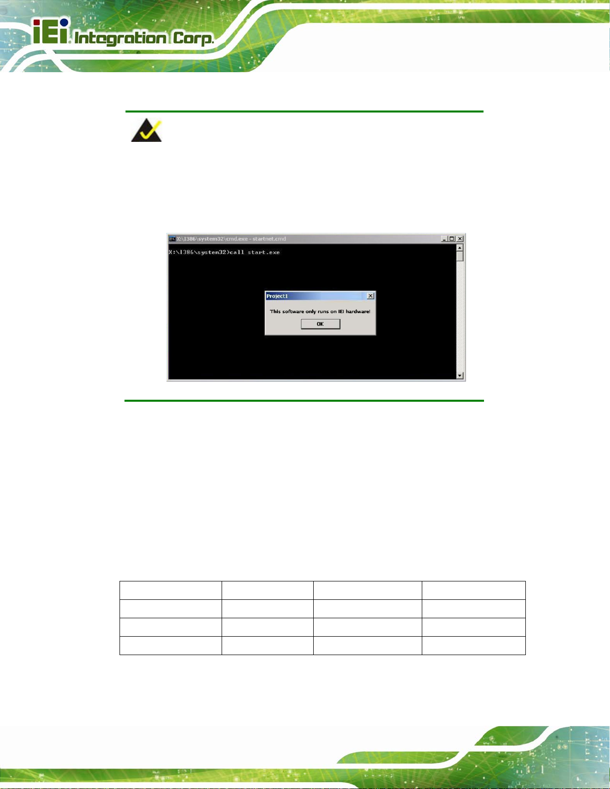
B.1.1 System Requirement
NOTE:
The recovery CD can only be used with IEI products. The software will
fail to run and a warning message will appear when used on non-IEI
hardware.
AFL2-W15A-N270 Panel PC
To create the system backup, the main storage device must be split into two partitions
(three partitions for Linux). The first partition will be for the operating system, while the
second partition will be invisible to the operating system and contain the backup made by
the one key recovery software.
The partition created for recovery images must be big enough to contain both the factory
default image and the user backup image. The size must be calculated before creating the
partitions. Please take the following table as a reference when calculating the size of the
partition.
OS OS Image after Ghost Compression Ratio
Windows® 7 7 GB 5 GB 70%
Windows® XPE 776 MB 560 MB 70%
Windows® CE 6.0 36 MB 28 MB 77%
Page 88
 Loading...