

Page 1

AFL2-W07A-N26
Page I
AFL2-W07A-N26
MODEL:
Flat Bezel Panel P C with 1.6 GHz Intel® Atom™ N2600 processor,
Rev. 1.0 0 - 19 Feb ruar y, 2013
IEI Technology Corp.
Touch Screen, Wi-Fi, USB, GbE LAN , RS-232/422/485,
HD Audio and RoHS
User Manual
User Manual
Page 2
AFL2-W07A-N26
Page II
Date Version Changes
Revis ion
19 February, 2013 1.00
Initial release
Page 3

AFL2-W07A-N26
Page III
Copyright
COP YRIGHT NOTICE
The information in this document is subject to change without prior notice in order to
improve reliabilit y, design a nd functi on and d oes not r epresent a com mitm ent on the part
of the manufacturer.
In no event will the manufacturer be liable for direct, indirect, special, incidental, or
consequential damages arising out of the use or inability to use the product or
documentation, even if advised of the possibility of such damages.
This document contains proprietary information protected by copyright. All rights are
reserved. No part of this manual may be reproduced by any mechanical, e lectronic, or
other means in any form without prior written permission of the manufacturer.
TRADEMARKS
All registered tradem ark s and produc t nam es ment ioned here in are us ed for identif icatio n
purposes only and m ay be trademarks and/or registe red trademarks of their respecti ve
owners.
Page 4

AFL2-W07A-N26
Page IV
Table of Con tents
1 INTRODUCTION .......................................................................................................... 1
1.1 AFL2-W07A-N26 FL AT BEZEL PANEL PC OVERVIEW ............................................... 2
1.1.1 Model Variations ................................................................................................ 3
1.1.2 Features ............................................................................................................. 3
1.2 EXTERNAL OVERVIEW ................................................................................................ 3
1.2.1 Front Panel ........................................................................................................ 3
1.2.1.1 LED Indicators ............................................................................................ 4
1.2.2 Rear Panel ......................................................................................................... 6
1.2.3 Bottom Panel ...................................................................................................... 7
1.3 INTERNAL OVERVIEW ................................................................................................. 8
1.4 SYSTEM SPECIFICATIONS ............................................................................................ 8
2 DETAILED SPECIFICATIONS ................................................................................. 11
2.1 DIMENSIONS ............................................................................................................. 12
2.2 INTEL® ATOM™ PROCESSOR ................................................................................... 13
2.3 MOTHERBOARD COMPONENTS ................................................................................. 13
2.3.1 Memory Capacity ............................................................................................. 13
2.3.2 Storage Capacity .............................................................................................. 13
2.4 EXTERNAL PERIPHERAL INTERFACE CONNECTORS ................................................... 13
2.4.1 Serial Port Connectors .................................................................................... 13
2.4.2 LAN Connectivity ............................................................................................. 14
2.4.3 External USB Connectors ................................................................................ 14
2.5 AUDIO ...................................................................................................................... 15
2.5.1 Audio Codec Controller ................................................................................... 15
2.5.2 Stereo Speakers ................................................................................................ 16
3 UNPACKING ............................................................................................................... 17
3.1 UNPACKING .............................................................................................................. 18
3.1.1 Packing List ..................................................................................................... 18
4 INSTALLATION ......................................................................................................... 21
Page 5

AFL2-W07A-N26
Page V
4.1 ANTI-STATIC PRECAUTIONS ...................................................................................... 22
4.2 INSTALLATION PRECAUTIONS ................................................................................... 22
4.3 INST ALLATION AND CONFIGURATION STEPS ............................................................. 23
4.4 MSATA CARD INSTALLATION ................................................................................... 23
4.5 RFID READER (OPTIONAL) ...................................................................................... 25
4.6 AT/ATX MODE SELECTION ...................................................................................... 27
4.6.1 AT Power Mode ................................................................................................ 27
4.6.2 ATX Power Mode ............................................................................................. 27
4.7 CLEAR CMOS .......................................................................................................... 28
4.8 RESET THE SYSTEM .................................................................................................. 28
4.9 POWERING ON THE SYSTEM ..................................................................................... 29
4.10 POWERING OFF THE SYSTEM .................................................................................. 29
4.11 MOUNTING THE SYSTEM ........................................................................................ 29
4.11.1 W all Mounting ................................................................................................ 30
4.11.2 Panel Mounting .............................................................................................. 33
4.11.3 Stand Mounting .............................................................................................. 35
4.12 EXTERNAL PERIPHERAL DEVICE CONNECTION ...................................................... 35
4.12.1 Audio Connection ........................................................................................... 36
4.12.2 Display Device Connection ............................................................................ 37
4.12.3 LAN Connection ............................................................................................. 37
4.12.4 Serial Device Connection .............................................................................. 38
4.12.4.1 DB-9 Serial Port Connection .................................................................. 38
4.12.4.2 RJ-11 Serial Port Connection .................................................................. 39
4.12.5 USB Device Connection ................................................................................. 41
5 SYSTEM MOTHERBOARD ..................................................................................... 43
5.1 OVERVIEW ................................................................................................................ 44
5.1.1 Layout .............................................................................................................. 44
5.2 INTERNAL PERIPHERAL CONNECTORS ...................................................................... 45
5.2.1 Audio Connector (AUDIO1) ............................................................................ 46
5.2.2 Auto-dimming Connector (IR1) ....................................................................... 47
5.2.3 Battery Connector (BAT1) ............................................................................... 47
5.2.4 BIOS Programming Connector (SPI1) ............................................................ 47
5.2.5 Bluetooth Connector (BLUETOOTH1) ........................................................... 47
5.2.6 Debug Port Connector (LPC_DEBUG1) ........................................................ 48
Page 6

AFL2-W07A-N26
Page VI
5.2.7 EC Firmware Connector (JSPI1) .................................................................... 48
5.2.8 Hot Key Connector (HOT_KEY1) ................................................................... 48
5.2.9 K Type Connector (K_TYPE1, K_TYPE2) ....................................................... 48
5.2.10 LCD Inverter Connector (INVERTER1) ........................................................ 49
5.2.11 LCD LVDS connector (JR1) ........................................................................ 49
5.2.12 LED Connector (LEDCN1) ............................................................................ 49
5.2.13 LPT Connector (LPT_DB1) ........................................................................... 50
5.2.14 Micro SD Connector (MICRO_SD1) ............................................................. 50
5.2.15 Mini USB Connector (MINI_USB1) .............................................................. 50
5.2.16 Microphone Connector (WEBCAM_DMIC1) ................................................ 51
5.2.17 Power Button Connector (PW_BT1) ............................................................. 51
5.2.18 RFID USB Connector (RFID1) ..................................................................... 51
5.2.19 Speaker Connector (AMP_SPKR1) ............................................................... 51
5.2.20 Touch Panel Connector (TS1) ........................................................................ 51
5.2.21 Touch Panel Connector (CAP_TS1) .............................................................. 52
5.2.22 VGA Connector (VGA1) ................................................................................ 52
5.2.23 Webcam Connector (CAMERA1) ................................................................... 52
5.3 EXTERNAL INTERFACE PANEL CONNECTORS ............................................................ 53
5.3.1 Display Port Connector (DISPLAY_PORT1) .................................................. 54
5.3.2 Ethernet Connector (LAN1) ............................................................................. 54
5.3.3 Power Connector (DC_IN1) ............................................................................ 55
5.3.4 RS-232 Serial Ports (COM1) ........................................................................... 55
5.3.5 RS-422/485 Serial Port (COM2) ..................................................................... 55
5.3.6 USB 2.0 Connectors (USB1) ............................................................................ 55
5.3.7 USB 3.0 Connectors (USB3_1) ........................................................................ 56
6 SYSTEM MAINTENANCE ....................................................................................... 57
6.1 SYSTEM MAINTENANCE INTRODUCTION .................................................................. 58
6.2 ANTI-STATIC PRECAUTIONS ...................................................................................... 58
6.3 TURN OFF THE POWER .............................................................................................. 59
6.4 OPENIN G THE SYSTEM .............................................................................................. 59
6.4.1 Removing the Back Cover ................................................................................ 59
6.4.2 Removing the Internal Aluminum Cover .......................................................... 60
6.5 REPLACING COMPONENTS ........................................................................................ 62
6.5.1 Memory Module Replacement ......................................................................... 62
Page 7

AFL2-W07A-N26
Page VII
6.5.2 WLAN Card Replacement ................................................................................ 63
6.6 REINSTALLING THE COVERS ..................................................................................... 66
7 BIOS SETUP ................................................................................................................ 67
7.1 INTRODUCTION ......................................................................................................... 68
7.1.1 Starting Setup ................................................................................................... 68
7.1.2 Using Setup ...................................................................................................... 68
7.1.3 Getting Help ..................................................................................................... 69
7.1.4 Unable to Reboot after Configuration Changes .............................................. 69
7.1.5 BIOS Menu Bar ................................................................................................ 69
7.2 MAIN ........................................................................................................................ 70
7.3 ADVANCED ............................................................................................................... 71
7.3.1 ACPI Settings ................................................................................................... 72
7.3.2 RTC Wake Settings ........................................................................................... 73
7.3.3 CPU Configuration .......................................................................................... 75
7.3.4 SATA Configuration ......................................................................................... 76
7.3.5 USB Configuration ........................................................................................... 77
7.3.6 F81866 Super IO Configuration ...................................................................... 78
7.3.6.1 Serial Port n Configuration ....................................................................... 79
7.3.7 H/W Monitor .................................................................................................... 81
7.3.8 Serial Port Console Redirection ...................................................................... 81
7.4 IEI FEATURE ............................................................................................................. 84
7.5 CHIPSET ................................................................................................................... 85
7.5.1 Host Bridge Configuration .............................................................................. 86
7.5.1.1 Intel IGD Configuration ............................................................................ 86
7.5.2 South Bridge Configuration ............................................................................. 88
7.6 BOOT ........................................................................................................................ 90
7.7 SECURITY ................................................................................................................. 92
7.8 SAVE & EXIT ............................................................................................................ 93
8 SOFTWARE DRIVERS .............................................................................................. 95
8.1 AVAILABLE SOFTWARE DRIVERS .............................................................................. 96
8.2 STARTING THE DRIVER PROGRAM ............................................................................ 96
8.3 CHIPSET DRIVER INSTALLATION ............................................................................... 97
8.4 GRAPHICS DRIVER INSTALLATION .......................................................................... 100
Page 8

AFL2-W07A-N26
Page VIII
8.5 TOUCH SCREEN DRIVER ......................................................................................... 103
8.5.1 Calibrating the Touch Screen ......................................................................... 107
8.6 AUDIO DRIVER INSTALLATION ............................................................................... 109
8.7 LAN DRIVER INSTALLATION ................................................................................... 111
8.8 USB 3.0 DRIVER INSTALLATION .............................................................................. 114
8.9 WI-FI DRIVER INSTALLATION .................................................................................. 116
8.10 BLUETOOTH DRIVER ............................................................................................ 120
8.11 AMCAP DRIVER INSTALLATION ........................................................................... 124
A SAFETY PRECAUTIONS ....................................................................................... 127
A.1 SAFETY PRECAUTIONS .......................................................................................... 128
A.1.1 General Safety Precautions ........................................................................... 128
A.1.2 CPU T empe ratur e Warning ........................................................................... 129
A.1.3 Anti-static Precautions .................................................................................. 129
A.1.4 Product Disposal ........................................................................................... 130
A.2 MAINTENANCE AND CLEANING PRECAUTIONS ...................................................... 130
A.2.1 Maintenance and Cleaning ............................................................................ 130
A.2.2 Cleaning T ools ............................................................................................... 131
B BIOS MENU OPTIONS ........................................................................................... 132
C ONE KEY RECOVERY ........................................................................................... 135
C.1 ONE KEY RECOVERY INTRODUCTION .................................................................... 136
C.1.1 System Requirement ...................................................................................... 137
C.1.2 Supported Operating System ......................................................................... 138
C.2 SETUP PROCEDURE FOR WINDOWS ........................................................................ 139
C.2.1 Hardware and BIOS Setup ............................................................................ 140
C.2.2 Create Partitions ........................................................................................... 140
C.2.3 Install Operating System, Drivers and Applications ..................................... 144
C.2.4 Building the Recovery Partition .................................................................... 145
C.2.5 Create Factory Default Image ...................................................................... 147
C.3 AUTO RECOVERY SETUP PROCEDURE .................................................................... 152
C.4 SETUP PROCEDURE FOR LINUX .............................................................................. 156
C.5 RECOVERY TOOL FUNCTIONS ................................................................................ 160
C.5.1 Factory Restore ............................................................................................. 161
C.5.2 Backup System ............................................................................................... 162
Page 9

AFL2-W07A-N26
Page IX
C.5.3 Restore Your Last Backup .............................................................................. 163
C.5.4 Manual .......................................................................................................... 164
C.6 RESTORE SYSTEMS FROM A LINUX SERVER THROUGH LAN .................................. 165
C.6.1 Configure DHCP Server Settings .................................................................. 166
C.6.2 Configure TFTP Settings ............................................................................... 167
C.6.3 Configure One Key Recovery Server Settings ............................................... 168
C.6.4 Start the DHCP, TFTP and HTTP ................................................................. 169
C.6.5 Create Shared Directory ................................................................................ 169
C.6.6 Setup a Client System for Auto Recovery ...................................................... 170
C.7 OTHER INFORMATION ............................................................................................ 173
C.7.1 Using AHCI Mode or ALi M5283 / VIA VT6421A Controller ...................... 173
C.7.2 System Memory Requirement ........................................................................ 175
D HAZARDOUS MATERIALS DISCLOSURE ....................................................... 176
D.1 HAZARDOUS MATERIAL DISCLOSURE TABLE FOR IPB PRODUCTS CERTIFIED AS
ROHS COMPLIANT UNDER 2002/95/EC WITHOUT MERCURY ..................................... 177
Page 10

AFL2-W07A-N26
Page X
List of Figures
Figure 1-1: AFL2-W07A-N26 Flat Bezel Panel PC ........................................................................ 2
Figure 1-2: AFL2-W07A-N26 Front View
Figure 1-3: LED Indicators
Figure 1-4: Function Keys
Figure 1-5: AFL2-W07A-N26 Rear View
Figure 1-6: AFL2-W07A-N26 Bottom Panel
Figure 2-1: AFL2-W07A-N26 Dimensions (mm)
Figure 2-2: Serial Ports
Figure 2-3: RJ-45 Ethernet Connector (Bottom Panel)
Figure 2-4: External USB Ports (Bottom Panel)
Figure 2-5: Audio Jack
Figure 4-1: mSATA Cover Retention Screw
Figure 4-2: PCIe Mini Card Slot
Figure 4-3: PCIe Mini Card Installation
Figure 4-4: Connect the RFID USB cable
Figure 4-5: Install the RFID module
Figure 4-6: AT/ATX Switch Location
Figure 4-7: Clear CMOS Switch Location
....................................................................................... 4
............................................................................................................. 4
............................................................................................................. 6
........................................................................................ 7
.................................................................................. 8
.........................................................................12
................................................................................................................14
.............................................................14
........................................................................15
.................................................................................................................16
...............................................................................24
...................................................................................................24
.......................................................................................25
...................................................................................26
............................................................................................26
...........................................................................................27
...................................................................................28
Figure 4-8: Reset Button Location
Figure 4-9: Wall-mounting Bracket
Figure 4-10: Chassis Support Screws
Figure 4-11: Secure the Panel PC
Figure 4-12: Cutout Dimensions .................................................................................................33
Figure 4-13: Tighten the Panel Mounting Clamp Screws
Figure 4-14: Mounting screw location
Figure 4-15: Audio Connector
Figure 4-16: DisplayPort Connection
Figure 4-17: LAN Connection
Figure 4-18: DB-9 Serial Port Connector
Figure 4-19: RJ-11 Serial Port Connector
Figure 4-20: DB-9 Connector Pinout Locations
..............................................................................................29
.............................................................................................31
........................................................................................32
...............................................................................................33
.........................................................34
........................................................................................35
.....................................................................................................36
.........................................................................................37
......................................................................................................38
....................................................................................39
..................................................................................40
........................................................................40
Page 11

AFL2-W07A-N26
Page XI
Figure 4-21: USB Device Connection .........................................................................................41
Figure 5-1: System Motherboard (front)
Figure 5-2: System Motherboard (rear)
Figure 5-3: External Interface Panel Connectors
Figure 6-1: Back Cover Retention Screws
Figure 6-2: Internal Cover Retention Screws
Figure 6-3: Internal Components
Figure 6-4: DDR SO-DIMM Module Installation
Figure 6-5: Releasing the WLAN Card
Figure 6-6: Removing the WLAN card
Figure 6-7: Attaching the Antennas
Figure 8-1: Drivers
Figure 8-2: Chipset Driver Screen
Figure 8-3: Chipset Driver Welcome Screen
Figure 8-4: Chipset Driver License Agreement
Figure 8-5: Chipset Driver Read Me File
Figure 8-6: Chipset Driver Setup Operations
Figure 8-7: Graphics Driver Welcome Screen
.....................................................................................44
......................................................................................45
......................................................................53
.................................................................................60
.............................................................................61
................................................................................................61
..........................................................................63
........................................................................................64
........................................................................................64
............................................................................................65
........................................................................................................................97
...............................................................................................98
..............................................................................98
.........................................................................99
....................................................................................99
..........................................................................100
.........................................................................101
Figure 8-8: Graphics Driver License Agreement
Figure 8-9: Graphics Driver Read Me File
Figure 8-10: Graphics Driver Setup Operati o n s
Figure 8-11: Graphics Driver Installation Finish Screen
Figure 8-12: Touch Screen Driver Welcome Screen
Figure 8-13: Touch Screen Driver License Agreement
Figure 8-14: Touch Screen Driver Choose Install Location
Figure 8-15: Touch Screen Driver Installation Screen ............................................................106
Figure 8-16: Touch Screen Driver Update Complete
Figure 8-17: PenMount Monitor Icon
Figure 8-18: PenMount Monitor Popup Menu
Figure 8-19: Configuration Screen
Figure 8-20: Calibration Initiation Screen
Figure 8-21: Calibration Screen
Figure 8-22: Audio Driver – Extracting Files
Figure 8-23: Audio Driver Welcome Screen
Figure 8-24: Audio Driver Installation
.....................................................................101
................................................................................102
......................................................................102
........................................................103
...............................................................104
...........................................................104
...................................................105
..............................................................106
........................................................................................107
..........................................................................107
............................................................................................108
................................................................................108
................................................................................................109
............................................................................110
.............................................................................110
.......................................................................................111
Page 12

AFL2-W07A-N26
Page XII
Figure 8-25: Audio Driver Installation Complete .....................................................................111
Figure 8-26: LAN Driver Welcome Screen
Figure 8-27: LAN Driver Ready to Install Screen
Figure 8-28: LAN Driver Setup Status Screen
Figure 8-29: LAN Driver Installatio n Complete
Figure 8-30: USB 3.0 Driver Welcome Screen
Figure 8-31: USB 3.0 Driver License Agreement
Figure 8-32: USB 3.0 Driver Installation
Figure 8-33: USB 3.0 Driver Update Complete
Figure 8-34: License Agreement
Figure 8-35: Setup Type
Figure 8-36: Configuration Tool
Figure 8-37: Ready to Install the Program
Figure 8-38: Setup Status
Figure 8-39: Installation Complete
Figure 8-40: Welcome Screen
Figure 8-41: License Agreement
Figure 8-42: Bluetooth Driver Destination Folder
...............................................................................112
.....................................................................112
.........................................................................113
........................................................................113
.........................................................................114
.....................................................................115
...................................................................................115
........................................................................116
...............................................................................................117
.............................................................................................................117
................................................................................................118
...............................................................................118
..........................................................................................................119
............................................................................................120
...................................................................................................121
...............................................................................................121
...................................................................122
Figure 8-43: Ready to Install the Program
Figure 8-44: Installing BlueSoleil
Figure 8-45: Bluetooth Driver Complete Installation Screen
Figure 8-46: Reboot the Computer
Figure 8-47: AMCap Driver Welcome Screen
Figure 8-48: AMCap Driver Choose Install Location
Figure 8-49: AMCap Driver Installatio n Complete
Figure C-1: IEI One Key Recovery Tool Menu
Figure C-2: Launching the Recovery Tool
Figure C-3: Recovery Tool Setup Menu
Figure C-4: Command Prompt
Figure C-5: Partition Creation Commands
Figure C-6: Launching the Recovery Tool
Figure C-7: Manual Recovery Environment fo r Windows
Figure C-8: Building the Recovery Partition
Figure C-9: Press Any Key to Continue
Figure C-10: Press F3 to Boot into Recovery Mode
...............................................................................122
..............................................................................................123
.................................................123
...........................................................................................124
..........................................................................125
...............................................................125
...................................................................126
.........................................................................136
...............................................................................141
...................................................................................141
..................................................................................................142
...............................................................................143
...............................................................................145
......................................................145
............................................................................146
...................................................................................146
................................................................147
Page 13

AFL2-W07A-N26
Page XIII
Figure C-11: Recovery Tool Menu ............................................................................................147
Figure C-12: About Symantec Ghost Window
Figure C-13: Symantec Ghost Path
Figure C-14: Select a Local Source Drive
Figure C-15: Select a Source Partition from Basic Drive
Figure C-16: File Name to Copy Image to
Figure C-17: Compress Image
Figure C-18: Image Creation Confirmation
Figure C-19: Image Creation Complete
Figure C-20: Image Creation Complete
Figure C-21: Press Any Key to Continue
Figure C-22: Auto Recovery Utility
Figure C-23: Launching the Recovery Tool
Figure C-24: Auto Recovery Environment for Windows
Figure C-25: Building the Au to Recovery Partition
Figure C-26: Factory Default Image Confirmation
Figure C-27: Image Creation Complete
Figure C-28: Press any key to continue
.........................................................................148
..........................................................................................148
................................................................................149
.......................................................149
................................................................................150
...................................................................................................150
..............................................................................151
....................................................................................151
....................................................................................151
.................................................................................152
...........................................................................................153
.............................................................................153
........................................................153
.................................................................154
..................................................................154
....................................................................................155
...................................................................................155
Figure C-29: Partitions for Linux
Figure C-30: Manual Recovery Environment for Linux
Figure C-31: Access menu.lst in Linux (Text Mode)
Figure C-32: Recovery Tool Menu
Figure C-33: Recovery Tool Main Menu
Figure C-34: Restore Factory Default
Figure C-35: Recovery Complete Window
Figure C-36: Backup System
Figure C-37: System Backup Complete Window
Figure C-38: Restore Backup
Figure C-39: Restore System Backup Complete Window
Figure C-40: Symantec Ghost Window
...............................................................................................157
..........................................................158
...............................................................159
............................................................................................159
...................................................................................160
.......................................................................................161
...............................................................................162
.....................................................................................................162
....................................................................163
....................................................................................................163
......................................................164
....................................................................................164
Page 14

AFL2-W07A-N26
Page XIV
List of Tables
Table 1-1: AFL2-W07A-N26 Model Variations .............................................................................. 3
Table 1-2: LED Indicators
Table 1-3: Function Key Descriptions
Table 1-4: System Specifications
Table 4-1: DB-9 Connector Pinout
Table 5-1: Peripheral Interface Connectors
Table 5-2: Audio Connector Pinouts (AUDIO1)
Table 5-3: Auto-dimming Connector Pinouts (IR1)
Table 5-4: Battery Connector Pinouts (BAT1)
Table 5-5: BIOS Programming Connector Pinouts (SPI1)
Table 5-6: Bluetooth Connector Pinouts (BLUETOOTH1)
Table 5-7: Debug Port Connector Pinouts (LPC_DEBUG1)
Table 5-8: EC Firmware Connector Pinouts (JSPI1)
Table 5-9: Hot Key Connector Pinouts (HOT_KEY1)
Table 5-10: K Type Connector Pinouts (K_TYPE1, K_TYPE2)
Table 5-11: LCD Inverter Connector Pinouts (INVERTER1)
Table 5-12: LCD LVDS connector Pinouts (JR1)
Table 5-13: LED Connector Pinouts (LEDCN1)
.............................................................................................................. 5
.......................................................................................... 6
................................................................................................10
..............................................................................................40
...............................................................................46
.........................................................................47
...................................................................47
...........................................................................47
........................................................47
........................................................47
.....................................................48
.................................................................48
................................................................48
.................................................48
.....................................................49
.......................................................................49
.........................................................................50
Table 5-14: LPT Connector Pinouts ( LPT_DB1)
Table 5-15: Micro SD Connector Pinouts (MICRO_SD1)
Table 5-16: Mini USB Connector Pinouts (MINI_USB1)
Table 5-17: Microphone Connector Pinouts (WEBCAM_DMIC1)
Table 5-18: Power Button Connector Pinouts (PW_BT1)
Table 5-19: RFID USB Connector Pinouts (RFID1)
Table 5-20: Speaker Connector Pinouts (AMP_SPKR1)
Table 5-21: Touch Panel Connector Pinouts (TS1)
Table 5-22: Touch Panel Connector Pinouts (CAP_TS1)
Table 5-23: VGA Connector Pinouts (VGA1)
Table 5-24: Webcam Connector Pinouts (CAMERA1)
Table 5-25: Rear Panel Connectors
Table 5-26: Display Port Connector Pinouts (DISPLAY_PORT1)
.......................................................................50
..........................................................50
............................................................50
.............................................51
.........................................................51
....................................................................51
...........................................................51
...................................................................52
.........................................................52
.............................................................................52
..............................................................52
............................................................................................53
............................................54
Page 15

AFL2-W07A-N26
Page XV
Table 5-27: Ethernet Connector Pinouts (LAN1) .......................................................................54
Table 5-28: Power Connector Pinouts (DC_IN1)
Table 5-29: RS-232 Serial Ports Pinouts (COM1)
Table 5-30: RS-422/485 Seri al Port Pinouts (COM2)
Table 5-31: USB 2.0 Connectors Pinouts (USB1)
Table 5-32: USB 3.0 Connector Pinouts (USB3_1)
Table 7-1: BIOS Navigation Keys
.......................................................................55
......................................................................55
.................................................................55
......................................................................55
....................................................................56
................................................................................................69
Page 16

AFL2-W07A-N26
Page XVI
List of BIOS Menus
BIOS Menu 1: Main .......................................................................................................................70
BIOS Menu 2: Advanced
BIOS Menu 3: ACPI Configuration
BIOS Menu 4: RTC Wake Settings
BIOS Menu 5: CPU Configuration
BIOS Menu 6: IDE
BIOS Menu 7: USB Configuration
BIOS Menu 8: Super IO Configuration
BIOS Menu 9: Serial Port n Configuration Menu
BIOS Menu 10: Hardware Health Configuration
BIOS Menu 11: Serial Port Console Redirection
BIOS Menu 12: iEi Feature
BIOS Menu 13: Chipset
BIOS Menu 14: Host Bridge Configuration
BIOS Menu 15: Intel IGD Configuration
BIOS Menu 16: Southbridge Chipset Configuration
BIOS Menu 17: Boot
BIOS Menu 18: Security
Configuration .................................................................................................76
..............................................................................................................72
..............................................................................................72
..............................................................................................73
...............................................................................................75
...............................................................................................77
........................................................................................78
.......................................................................79
........................................................................81
.......................................................................82
...........................................................................................................84
................................................................................................................85
................................................................................86
......................................................................................87
.................................................................88
.....................................................................................................................90
...............................................................................................................92
BIOS Menu 19: Exit
BIOS Menu 20: iEi Feature
.......................................................................................................................93
.........................................................................................................156
Page 17

AFL2-W07A-N26
Page 1
Chapter
1
1 Introduction
Page 18

AFL2-W07A-N26
Page 2
1.1 AFL2-W07A-N26 Flat Bezel Panel PC Overview
Figure 1-1: AFL2-W07A-N26 Flat Bezel Panel PC
The AFL2-W07A-N26 is an Intel® Atom ™ N2600 processor powered flat bezel panel P C
with a rich variety of functions and peripher als. The AFL2-W07A-N26 is designed for easy
and simplified integration into kiosk and point-of-sales (POS) applications.
An Intel® NM10 chipset ensures optim al memory, graphics, and peripheral I/O support.
The system comes with one 2.0 GB of DDR3 SO-DIMM ensuring smooth data
throughputs with reduced bottlenecks and fast system access.
Two serial ports, two external USB 2.0 ports and two external USB 3.0 ports ensure
simplified connectiv ity to a variety of externa l peripheral devices. Wi-Fi capabilities and
one RJ-45 Ethernet conn ector provide the system with smooth connection to an exter nal
LAN.
Page 19
AFL2-W07A-N26
Page 3
1.1.1 Model Variations
The model variations of the AFL2-W07A-N26 Series are listed below.
Model No. Touch Screen Type Optional Features
AFL2-W07A-N26/R/2G-R10
Table 1-1: AFL2-W07A-N26 Model Variations
1.1.2 Features
The AFL2-W07A-N26 features are listed below:
Flat-bezel LCD with LED backlight
Intel® Atom™ N2600 dual core 1.6 GHz processor
One 800 MHz 204-pin DDR3 SO-DIMM slot (system max. 2GB) pre-installed
with 2GB
5-wire resistive type touch screen supported
Wi-Fi 802.11b/g/n 2T2R high speed wireless
EM or Mifare RFID reader
Built-in two 0.8W speakers and microphone
IP64 compliant front panel
Auto dimming control
5-Wire Resistive N/A
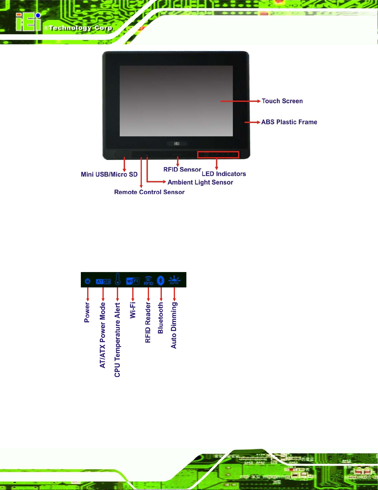
1.2 Externa l Overview
1.2.1 Front Panel
The front side of the AFL2-W07A-N26 is a flat bezel panel TFT LCD screen surrounded by
an ABS/PC plastic frame.
Page 20
AFL2-W07A-N26
Page 4
Figure 1-2: AFL2-W07A-N26 Front View
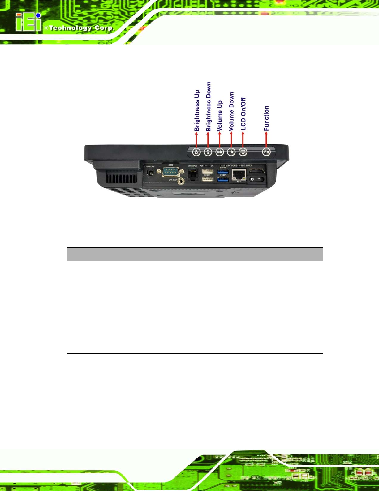
1.2.1.1 LED Indicators
There are seven LED ind icator lights located along th e front of the LCD screen (Figure
1-3).
Figure 1-3: LED Indicators
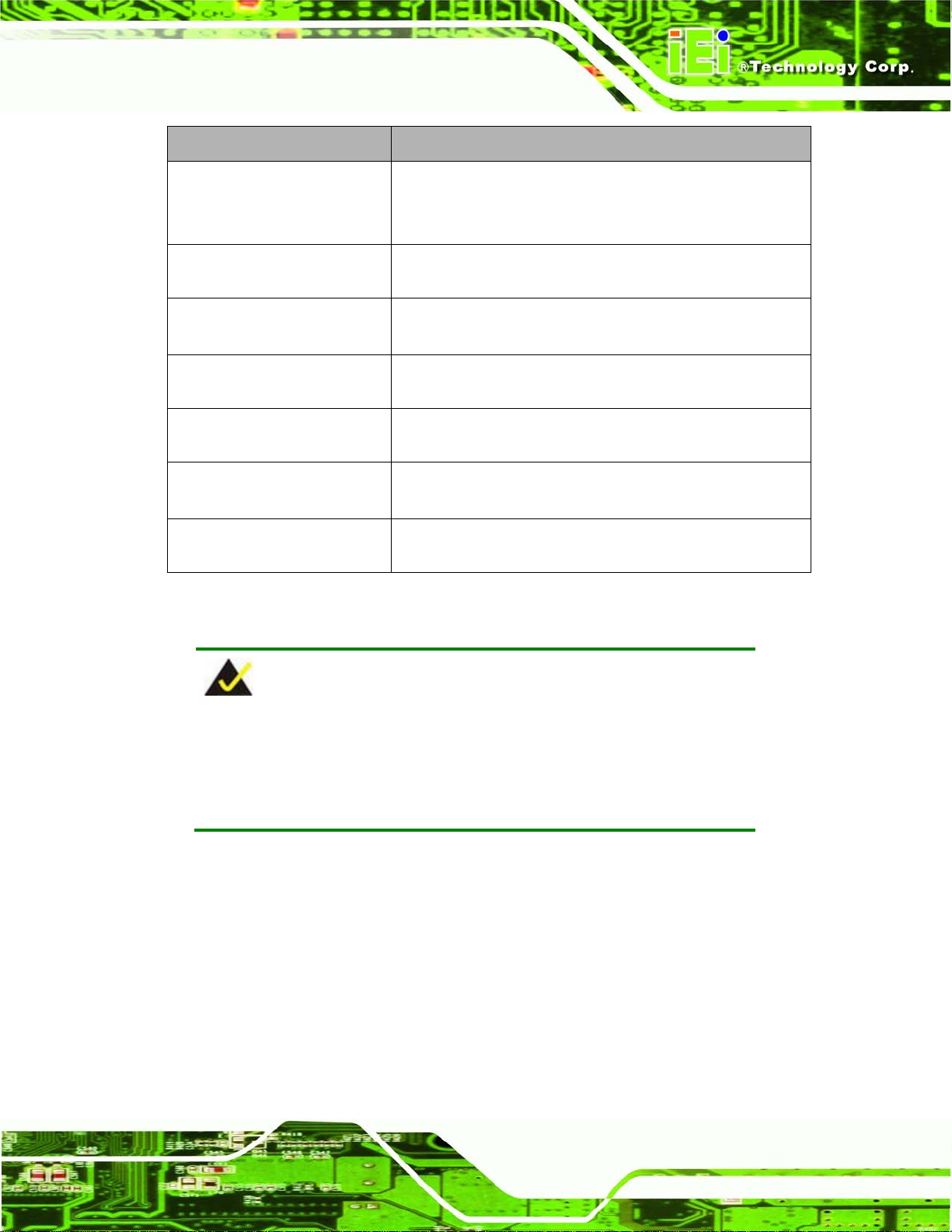
The descriptions of each LED indicator are listed below.
Page 21
AFL2-W07A-N26
Page 5
LED Indicator Des cription
Power
AT/ATX Mode
CPU Temperature Alert
Wi-Fi
RFID
Bluetooth
Auto Dimming
Table 1-2: LED Indicators
Shows power status.
Orange: Standby mode.
Blue: Power-on mode.
Shows the power mode status. Controlled by the AT/ATX
power mode switch.
BLUE: CPU temperature is normal.
RED: CPU temperature is too high.
The Wi-Fi module is enabled or disabled. Controlled by the
BIOS. See Section 7.5.2
The optional RFID reader is enabled or disabled.
Controlled by the hot keys. See Table 1-3
The Bluetooth module is enabled or disabled.
Controlled by the BIOS. See Section 7.5.2
The auto-dimming function is enabled or disabled.
Controlled by the BIOS. See Section 7.5.2
NOTE:
If the CPU temperature alert LED shows in red, the user must lower the
environments tem perature or close some running app lications to cool
down the CPU.
Page 22
AFL2-W07A-N26
Page 6
The corresponding Function Ke ys are located under the bottom right hand corner of the
LCD screen (Figure 1-4).
Figure 1-4: Function Keys
The Function Keys are described in Table 1-3:
Key Combin ation Function Key Des cription
Fn + LCD On/Off
Fn + Audio Volume Down
Fn + Brightness Down
Fn + Brightness Up
Fn: The function key can maintain for 2sec.
Table 1-3: Function Key Descriptions
RFID Enable/Disable
Audio Mute
Mini USB / Micro SD Enable/Disable
Power On/Off
Note: To power on the system, hold down the Fn +
Brightness Up buttons for 3 seconds. To power down the
system, hold down the FN + Brightness Up buttons for six
seconds.
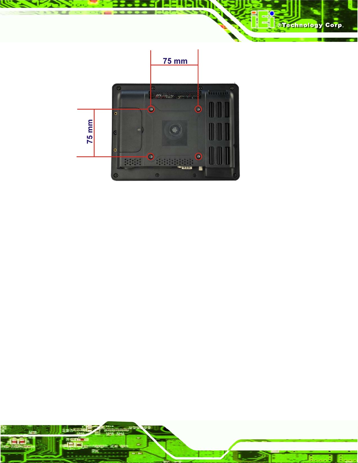
1.2.2 Rear Panel
The rear panel provid es access to retent ion screw holes that support the wall mounting.
Refer to Figure 1-5.
Page 23
AFL2-W07A-N26
Page 7
Figure 1-5: AFL2-W07A-N26 Rear View
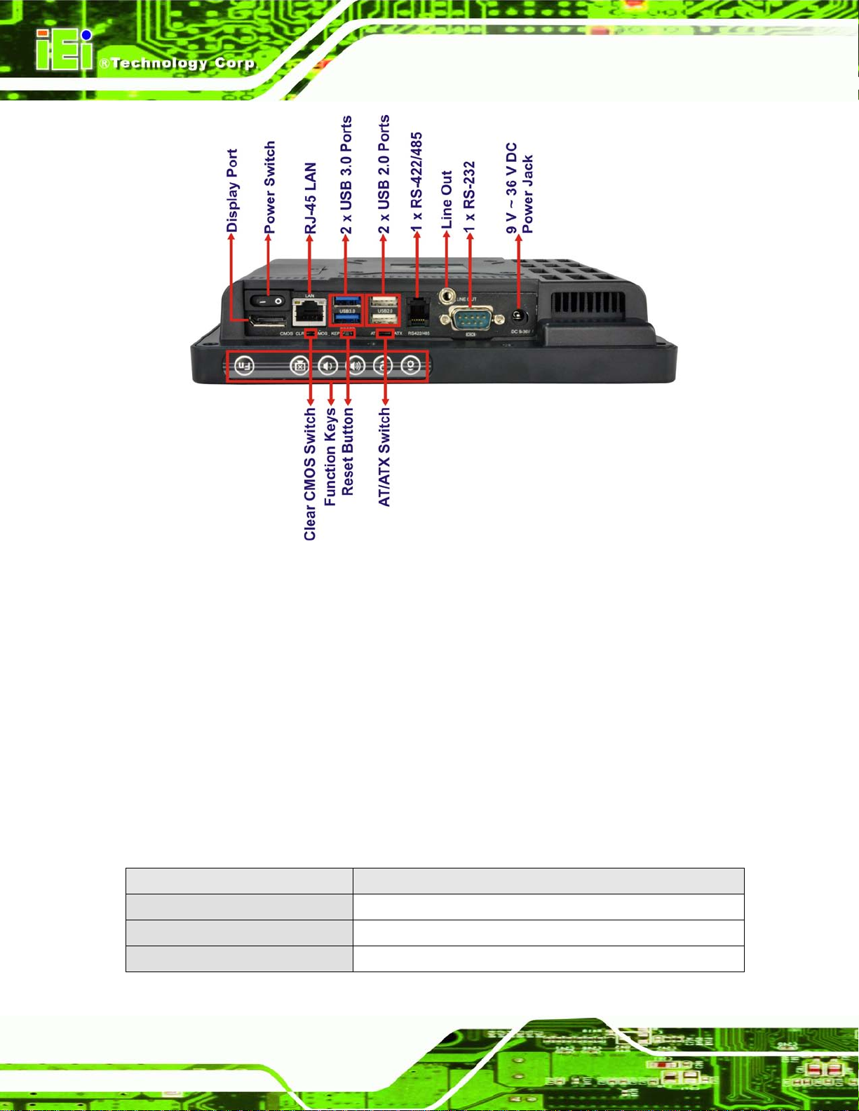
1.2.3 Bottom Panel
The bottom panel of the AFL2-W07A-N26 has the following features (Figure 1-6):
1 x AT/ATX Switch
1 × Audio jack (Line out)
1 x Clear CMOS switch
1 x 9V ~ 36V DC power jack
1 x Display port
6 x Function keys
1 x Power switch
1 x Reset button
1 x RJ-45 LAN connector
1 x RS-232 connector (DB-9)
1 x RS-422/485 connector (RJ-11)
2 x USB 2.0 connectors
2 x USB 3.0 connectors
Page 24
AFL2-W07A-N26
Page 8
Figure 1-6: AFL2-W07A-N26 Bottom Panel
1.3 Int ernal Ov er v iew
The AFL2-W07A-N26 has the following components installed internally:
1 x Motherboard
1 x 2.0 GB 800 MHz DDR3 SO-DIMM
1.4 S ys tem Specifications
The technical specifications for the AFL2-W07A-N26 systems are listed in
Table 1-4.
Specification AFL2-W07A-N26
LCD Size 8'' (4:3)
Max. Resolution 800 (W) x 600 (H)
Brightness (cd/m2) 250 cd/m²
Page 25

AFL2-W07A-N26
Page 9
Contrast Ratio 500:1
LCD Color 16.2 M
Pixel Pitch (H x V) (mm) 0.2025(H) x 0.2025(V)
Viewing Angle (H-V) 130°(H) / 110°(V)
Backlight MTBF (hr) 30000 hrs
Touch Screen 5-wire resistive typ e touc h screen
CPU Intel® Atom™ N2600 dual core 1.6 GHz CPU
Chipset Intel® NM10
Ethernet Realtek RTL8111E PCIe GbE controller support ASF2.0
Memory Support one 800 MHz 204-pin DDR3 SO-DIMM slot (max. 2G)
pre-installed with 2GB
Expansion 1 x PCIe x1 for Wi-Fi
SSD P CIe mSATA
Audio AMP 0.8 W + 0.8 W (built-in stereo speakers)
Microphone Digital Microphone
RFID Reader EM 125 KHz or MIFARE 13.56 MHz card reader (optional)
MSR card reader MSR card reader (optional)
Wireless 1 x Wireless LAN 802.11 b/g/n 2T2R module
(internal PCIe Mini card interface)
(Optional, internal USB interface, B lue too th V2 .0+ EDR )
OSD Function LCD on / off, brightness up / down, volume up / down, Hot Key
Construction Material ABS + PC plastic front frame
Mounting Wall, Panel, Stand and VESA 75 mm x 75mm
Front Panel Color Black
Net Weight 1.12 kg / 2.08 kg
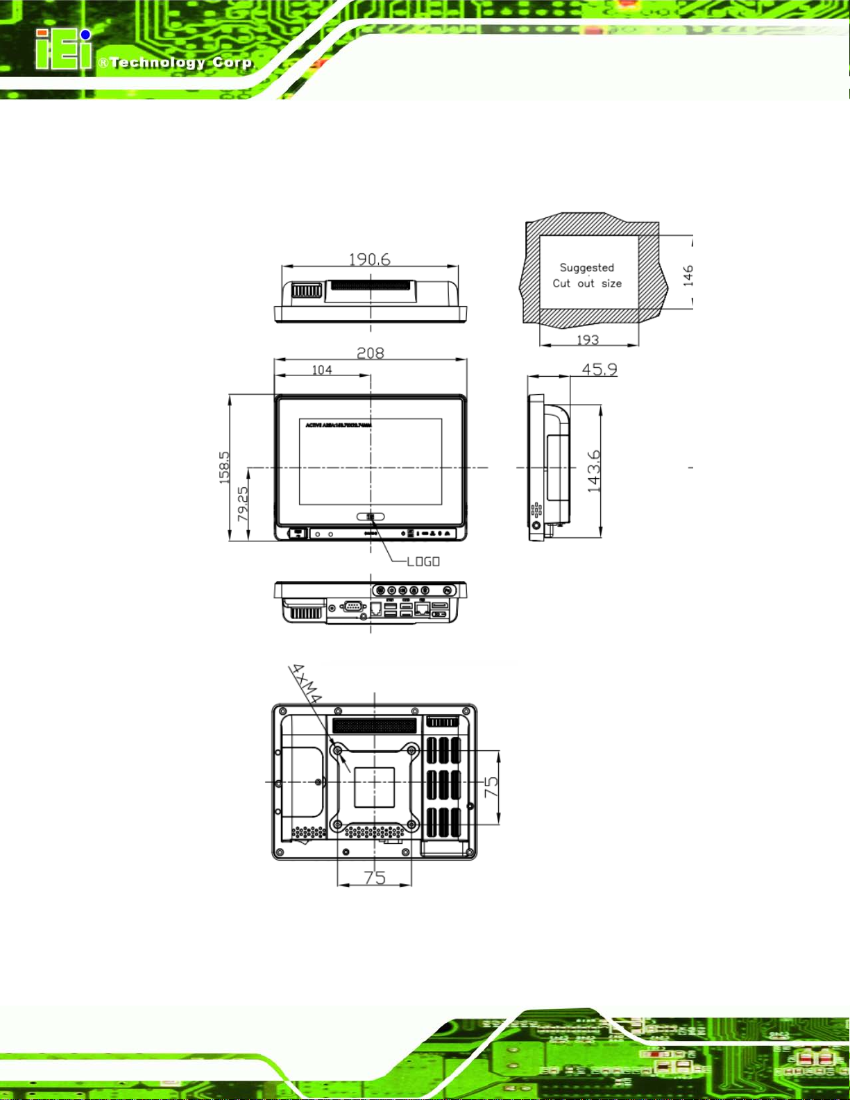
Dimensions (W x H x D) (mm) 208 (W) x 158.5 (H) x 45.9 (D)
Operation Temperature -20ºC ~ 40ºC
Storage Temperature -20ºC ~ 60ºC
IP level Front panel IP 64
Safety&EMC CE / FCC
Power Supply 36W power adapter
Power Requirement 9V ~ 36V DC
Power Consumption 19V@1.1A (Intel® Atom™ N2600 CPU with 2GB DDR3 memory )
Input: 90VAC~264VAC, 50/60 Hz, Output: 12VDC
Page 26
AFL2-W07A-N26
Page 10
I/O Ports and Switches 1 x RS-232 connector (DB-9)
1 x RS-422/485 connector (DJ-11)
1 x GbE LAN (RJ-45)
2 x USB 3.0 connectors
2 x USB 2.0 connectors
1 x Mini USB 2.0 connector (on front panel)
1 x Micro SD card slot (on front panel)
1 x Audio jack (line-out)
1 x Display port
1 x Power switch
1 x AT/ATX switch
1 x Reset button
1 x Clear CMOS button
1 x 9 V ~ 36V DC input jack
Table 1-4: System Specifications
Page 27

AFL2-W07A-N26
Page 11
Chapter
2
2 Detailed Specifications
Page 28
AFL2-W07A-N26
Page 12
2.1 Dimensions
The AFL2-W07A-N26 dimensions are shown below.
Figure 2-1: AFL2-W07A-N26 Dimensions (mm)
Page 29

AFL2-W07A-N26
Page 13
2.2 Intel® Atom™ Process or
An Intel® Atom™ N2600 processor is ins talled in the system. T he N2600 CPU is a 1.6
GHz dual core processor with Direct Media Inter face (DMI) speed of 2.5 GT/s. T he CPU
also features a 1.0 MB L2 cache.
2.3 Motherboard Components
The following sections describe some of the features on the motherboard.
2.3.1 Me mory Capacity
One 204-pin 2.0 GB 800 MHz DDR3 SO-DIMM is installed in the AFL2-W07A-N26 and
controlled by the Intel® Atom™ N2600 CPU installed on the internal motherboard.
2.3.2 Storage Capacity
The AFL2-W07A-N26 also supports a PCIe mSATA card which can be easily accessed by
removing one screw on the mSATA cover.
2.4 External Peripheral Interface Connectors
The following section describes the external peripheral interface connectors on the bottom
panel of the system.
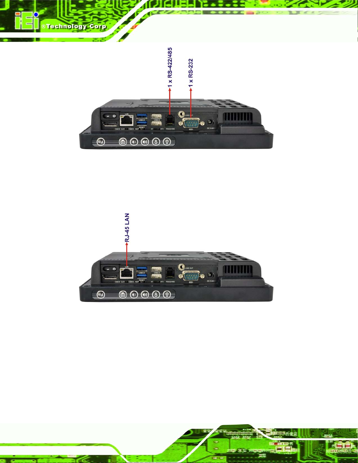
2.4.1 Se rial Port Connectors
The AFL2-W07A-N26 has one RS-232 serial port (DB-9) and one RS-422/485 serial port
(RJ-11). Enabling COM devices to be powered through the COM port eliminates
unnecessary and messy cabling.
Page 30
AFL2-W07A-N26
Page 14
Figure 2-2: Serial Ports
2.4.2 LAN Connectivity
The AFL2-W07A-N26 has one RJ-45 LAN connector on the bottom panel.
Figure 2-3: RJ-45 Ethernet Connector (Bottom Panel)
The PCIe LAN from the Intel® NM10 chipset of the AFL2-W07A-N26 is interfaced to the
Realtek RTL8111E PCIe giga bit Ethernet (GbE) controller. The R TL8111E controller is
connected directly to the RJ-45 connector and provides external GbE connectivity.
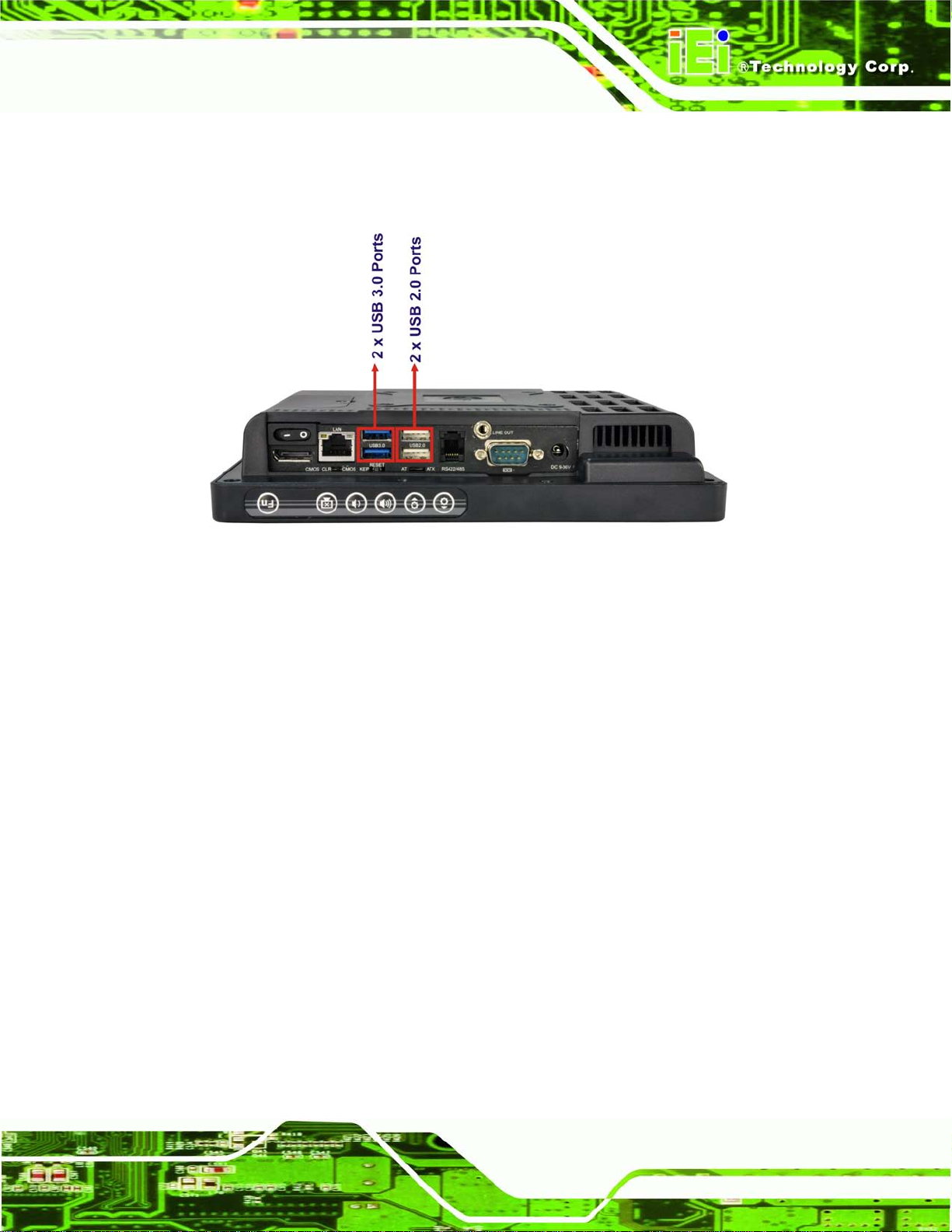
2.4.3 External USB Connectors
There are two USB 2.0 co nnectors and two USB 3.0 connector s on the bottom panel of
the AFL2-W07A-N26.All USB connectors are fully compliant with USB specification
Page 31
AFL2-W07A-N26
Page 15
Revision 2.0 and U SB specification Re vision 1.1 and can be interfaced t o both USB 1.1
and USB 2.0 compliant d evices. Only US B 3.0 connectors are c ompatible with USB 3.0
devices.
Figure 2-4: External USB Ports (Bottom Panel)
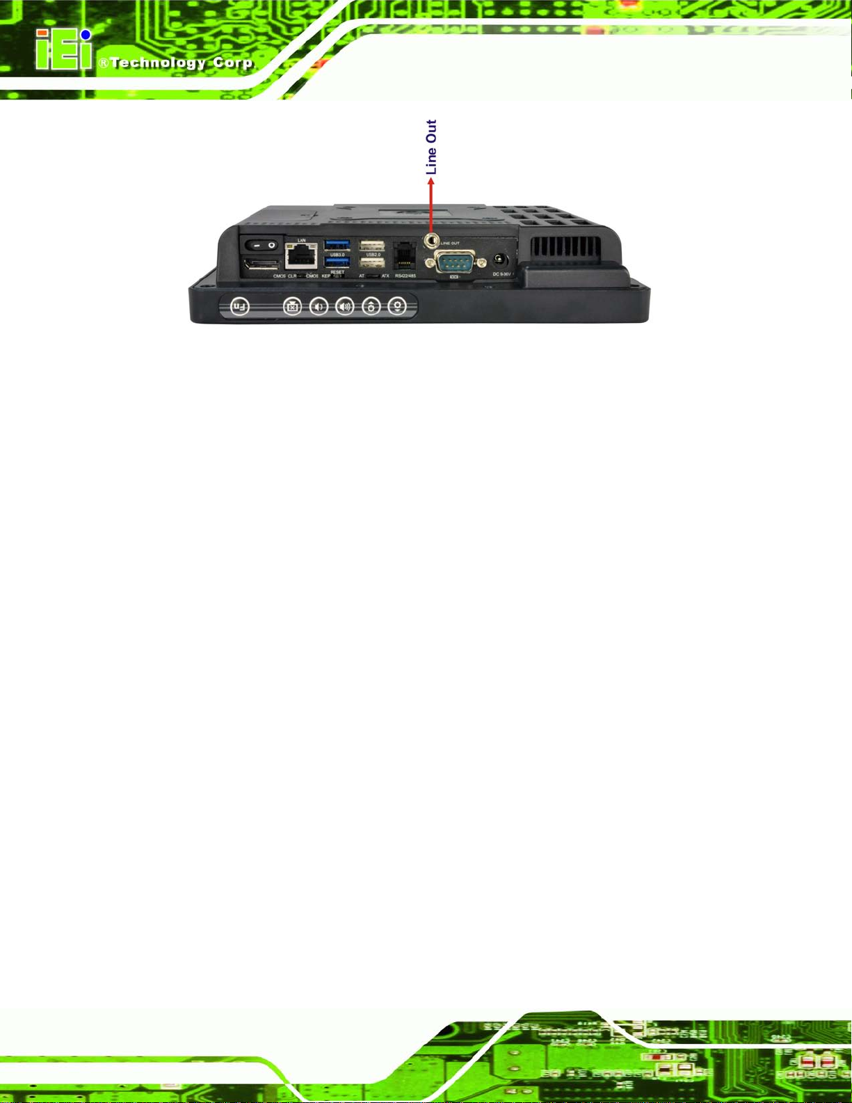
2.5 Audio
2.5.1 Audio Codec Controller
The integrated HD Audio compliant audio controller on the Intel® NM10 chipset is
integrated to a Realtek ALC892 audio codec. T he Realtek ALC892 is conn ected to one
external audio jack (Line out), which is then connec ted to compliant audi o device. The
Realtek ALC892 is a 7.1+2 channel high def initi on audio codec with ten DAC c ha nnels. It
supports 7.1 sound pla yback and 2 channe ls of independent stereo sou nd output. The
audio jack is shown in Figure 2-5.
Page 32
AFL2-W07A-N26
Page 16
Figure 2-5: Audio Jack
2.5.2 Stereo Speakers
Two internal 0.8 W stereo speakers on the sides of the AFL2-W07A-N26 are interfaced to
the system.
Page 33

AFL2-W07A-N26
Page 17
Chapter
3
3 Unpacking
Page 34

AFL2-W07A-N26
Page 18
3.1 Unpacking
To unpack the flat bezel panel PC, follow the steps below:
WARNING!
The front side LCD screen has a protective plastic cover stuck to the
screen. Only remove the plastic cover after the flat bezel panel PC has
been properly installed. This ensures the screen is protected during the
installation process.
Step 1: Use box cutters, a knife or a sharp pair of scissors that seals the top side of the
external (second) box.
Step 2: Open the external (second) box.
Step 3: Use box cutters, a knife or a sharp pair of scissors that seals the top side of the
internal (first) box.
Step 4: Lift the monitor out of the boxes.
Step 5: Remove both polystyrene ends, one from each side.
Step 6: Pull the plastic cover off the flat bezel panel PC.
Step 7: Make sure all the components listed in the packing list are present. Ste p 0:
3.1.1 Pack ing Lis t
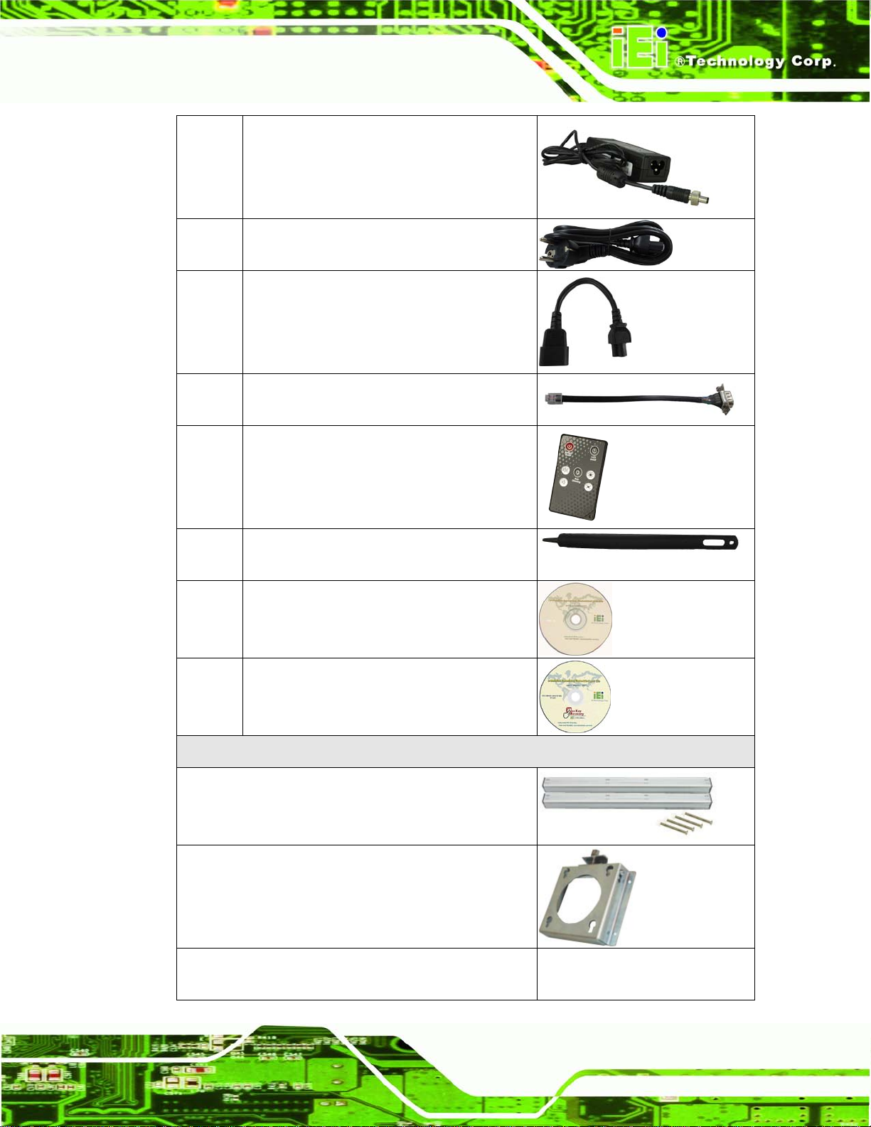
The AFL2-W07A-N26 flat bezel panel PC is shipped with the following components:
Quantity Ite m Im a g e
Standard
1 AFL2-W07A-N26 panel PC
Page 35
AFL2-W07A-N26
Page 19
1 Power adapter
1 Power cord
(P/N: 32702-000200-100-RS)
1 Power transfer cord
(P/N: 32702-000300-100-RS)
1 RJ-11 to DB-9 COM port cable
1 Infrared Remote Controller
(P/N: 7Z000-SLPCB001-RS)
1 Pen
(P/N: 43125-0002C0-00-RS)
1 Utility CD
1 One Key Recovery CD
Optional
Panel Mounting Kit
(P/N: AFL2PK-08A)
Wall mounting kit
(P/N: AFLWK-12)
Rack Mounting Kit
(P/N: AFL2RK-08A)
Page 36

AFL2-W07A-N26
Page 20
Stand
(P/N: STAND-A08/STAND-C12/STAND-100-RS)
V-stand
(P/N: VSTAND-A07/VSTAND-A10/VSTAND-A12)
Hybrid Card Reader
(P/N: AFL2P-07AMSI-U-R10)
Magnetic Stripe Reader
(P/N: AFL2P-07AMSR-U-R10)
OS: Win CE 6.0 (CD-ROM)
(P/N: AFL2-W07A-CV-CE060-R10)
OS: Win XPE (CD-ROM)
(P/N: AFL2-W07A-CV-XPE-R10)
OS: Linux (CD-ROM)
(P/N: AFL2-W07A-CV-LNX-R10)
OS: Win 7 Embedded (CD-ROM)
(P/N:
AFL2-W07A-CV-WES7E-R10 for Resistive Touch)
If any of these items are missing or damaged, contact the distributor or sales
representative imm ediately.
Page 37

AFL2-W07A-N26
Page 21
Chapter
4
4 Installation
Page 38

AFL2-W07A-N26
Page 22
in permanent damage to the
4.1 Anti-static Precautions
WARNING:
Failure to take ESD precautions during the maintenance of the
AFL2-W07A-N26 may result
AFL2-W07A-N26 and severe injury to the user.
Electrostatic discharge (ESD) can cause serious damage to electronic components,
including the AFL2-W07A-N26. Dry climates are especially susceptible to ESD. It is
therefore critical that when ever the AFL2-W07A-N26 i s accessed internall y, or any other
electrical component is handled, the fol lowing anti-static pr ecautions are strictl y adhered
to.
Wear an anti-static wristband: - Wearing a simple anti-static wristband can
help to prevent ESD from damaging the board.
Self-grounding: - Before handling the board touch any grounded conducting
material. During the time the board is handled, frequently touch any
conducting materials that are connected to the ground.
Use an anti-static pad: - When configuring the AFL2-W07A-N26, place it on
an antic-static pad. This reduces the possibility of ESD damaging the
AFL2-W07A-N26.
Only handle the edges of the PCB: - When handling the PCB, hold the PCB
by the edges.
4.2 Installation Precautions
When installing the flat bezel pane l PC, please follow the precautions listed below:
Power turned off: When installing the flat bezel panel PC, make sure the
power is off. Failing to turn off the power may cause severe injury to the body
and/or damage to the system.
Certified Engineers: Only certified engineers should install and modify
onboard functionalities.
Page 39
AFL2-W07A-N26
Page 23
cover screws will crack the plastic frame.
Anti-static Discharge: If a user open the rear panel of the flat bezel panel PC,
to configure the jumpers or plug in added peripheral devices, ground
themselves first and wear and anti-static wristband.
4.3 Installation and Configuration Steps
The following installation steps must be followed.
Step 1: Unpack the flat bezel panel PC.
Step 2: Install the mSATA card.
Step 3: Configure the system.
Step 4: Connect peripheral devices to the flat bezel panel PC.
Step 5: Mount the flat bezel panel PC. Ste p 0:
4.4 mS ATA card Installation
WARNING:
Over-tightening back
Maximum torque for cover screws is 5 kg-cm (0.36 lb-ft/0.49 Nm).
To install the mSATA card into the AFL2-W07A-N26, please follow the steps below:
Step 1: Remove one (1) retention screw from the mSATA cover (Figure 4-1).
Page 40

AFL2-W07A-N26
Page 24
Figure 4-1: mSATA Cover Retention Screw
Step 2: Remove the mSATA cover from the device.
Step 3: Locate the PCIe mini card slot on the motherboard. (Figure 4-2).
Figure 4-2: PCIe Mini Card Slot
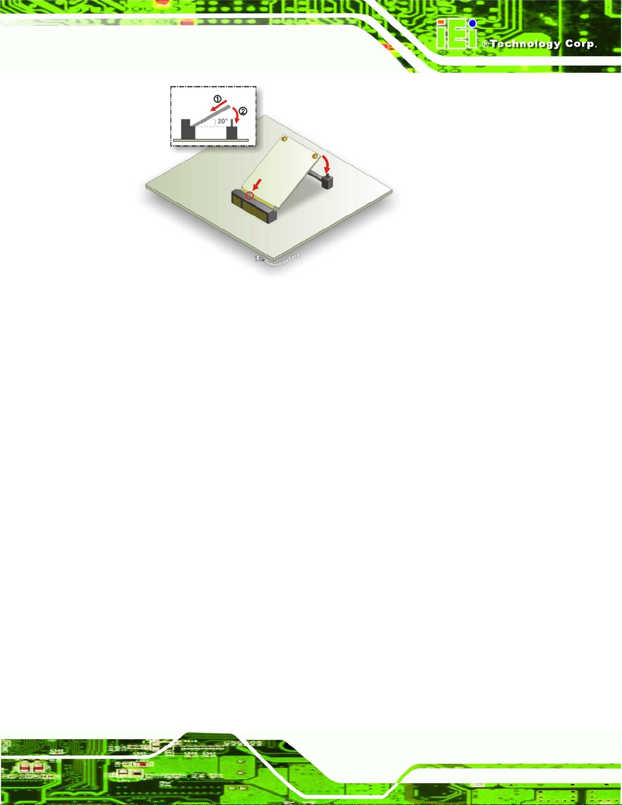
Step 4: Insert into the slot at an angle. Line up the notch on the card with the notch on
the connector. Slide the mSATA card into the slot at an angle of about 20º.
Page 41
AFL2-W07A-N26
Page 25
Figure 4-3: PCIe Mini Card Installation
Step 5: Push down until the card clips into place. Push the other end of the card down
until it clips into place on the plastic connector.
Step 6: Replace the mSATA cover and secur e it usin g one (1) retention screw.
4.5 RFID Re ad er (Optional)
The AFL2-W07A-N26 series (selected models only) suppor ts RFID reader functi on. The
RFID reader is locat ed at the bottom of the screen. An optional Mifare 13.56 MHz or EM
125 KHz RFID reader can be integrated in the system. All the data on the RFID tag can be
easily retrieved or upda ted through the reader to secure the data tra nsmission process
and increase efficienc y for certain ident it y group.
To install the RFID reader, follow the steps below.
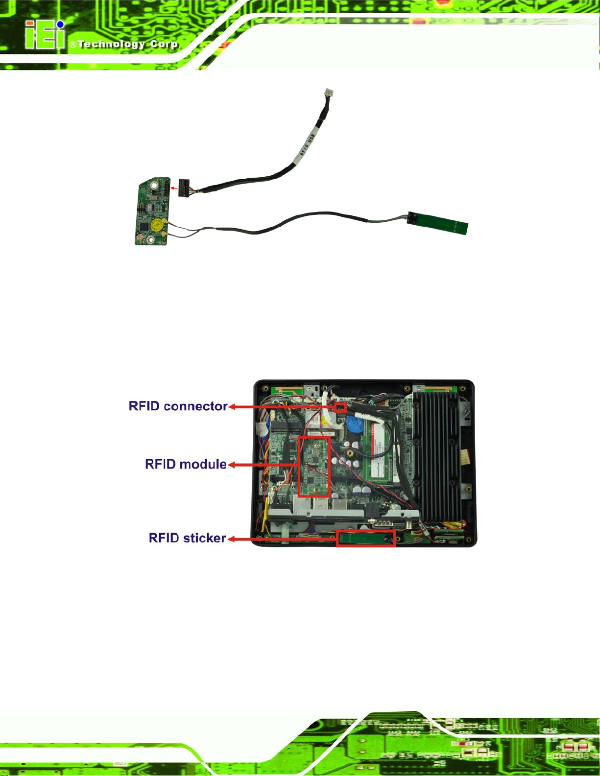
Step 1: Connect the RFID USB cable to the USB connector on the RFID reader module.
(Figure 4-4)
Page 42
AFL2-W07A-N26
Page 26
Figure 4-4: Connect the RFID USB cable
Step 7: Connect the RFID connector of the RFID USB cable to the RFID connector on
the motherboard (RFID1).
Step 8: Attach the sticker of the RFID module to the bottom of the panel.
Figure 4-5: Install the RFID module
Step 9: Secure the RFID module to the motherboard using two retention screws on
either side.
Step 10: Use the RFID reader to read a RFID card.
Page 43
AFL2-W07A-N26
Page 27
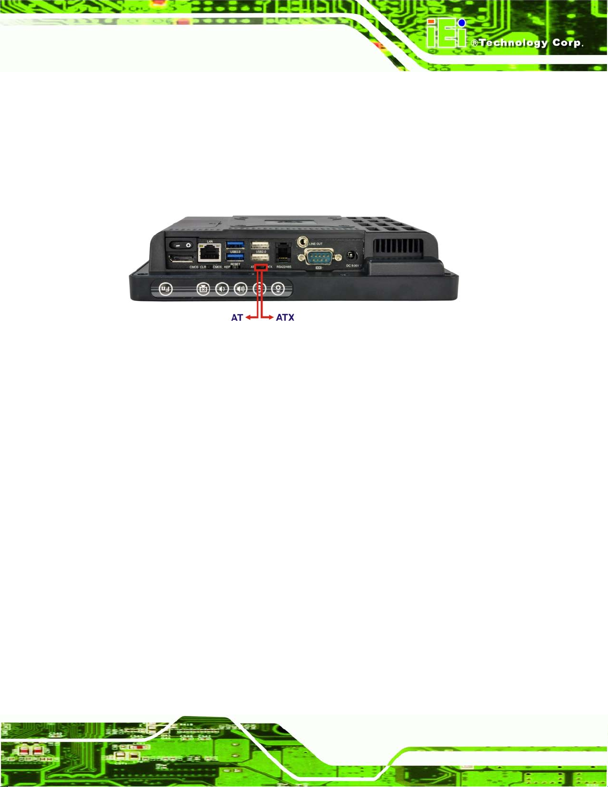
4.6 AT/ATX Mode Se lection
AT or ATX power mode can be used on the AFL2-W07A-N26. The selection is made
through an AT/ATX switch located on the bottom panel (Figure 4-6). To select AT mode or
ATX mode, follow the steps below.
Step 1: Locate the AT/ATX switch on the bottom panel (Figure 4-6).
Figure 4-6: AT/ATX Switch Location
Step 11: Adjust the A T/A TX switch. S tep 0:
4.6.1 AT Power Mode
With the AT mode selec ted, the po wer is control led by a central power un it rather than a
power switch. The AFL2-W07A-N26 panel PC turns on automatic ally when the power is
connected. The AT mode benefits a production lin e to control multi ple panel PCs from a
central management center and other applications including:
ATM
Self-service kiosk
Plant environment monitoring system
Factory automation platform
Manufacturing shop flow
4.6.2 ATX Power Mode
With the ATX mode selected, the AFL2-W07A-N26 panel PC goes in a standby mode
when it is turned of f. The panel PC can be easi ly turned on v ia network or a power switch
in standby mode. Remote po wer control is perfect for advertising appl ications since the
Page 44

AFL2-W07A-N26
Page 28
broadcasting time for each panel PC can be set individually and controlled remotely. Other
possible application includes
Security surveillance
Point-of-Sale (POS)
Advertising terminal
4.7 Clear CMOS
If the AFL2-W07A-N26 fails to boot due to improper BIOS settings, the clear CMOS switch
clears the CMOS data and resets the system BIOS information. To do this, adjust the
clear CMOS switch to clear CMOS mode for a few seconds then reinstall the clear CMOS
switch back to keep CMOS mode.
Step 2: Locate the clear CMOS switch on the bottom panel (Figure 4-7).
Figure 4-7: Clear CMOS Switch Location
Step 1: Adjust the clear CMOS switch. Ste p 0:
4.8 Reset the System
The reset button en ables user to reboot the s ystem when the system is turned on. To
reboot the system, follow the steps below.
Step 3: Locate the reset button on the bottom panel (Figure 4-8).
Page 45

AFL2-W07A-N26
Page 29
Figure 4-8: Reset Button Location
Step 1: Press the reset button. Step 0:
4.9 Powering On the System
To power on the system, follow the steps below:
Step 1: Locate the Function and Brightness Up function keys. See Section 1.2.1.1.
Step 2: Hold down the Function and Brightness Up buttons for three seconds to power
on the system. Step 0:
4.10 Po w ering Off the Syste m
To power off the system, follow the steps below:
Step 1: Locate the Function and Brightness Up function keys. See Section 1.2.1.1.
Step 2: Hold down the Function and Brightness Up buttons for six seconds to power off
the system. Ste p 0:
4.11 Mounting the Sys tem
WARNING!
Page 46

AFL2-W07A-N26
Page 30
When mounting the flat bezel panel PC onto an arm, onto the wall or onto a
panel, it is better to have more than o ne p er s on to he l p with th e i ns tal lat ion
to make sure the pane l PC does not fall down and get damaged.
The four methods of mounting the AFL2-W07A-N26 are listed below.
Wall mounting
Panel mounting
Stand mounting
The four mounting methods are described below.
4.11.1 Wall Mounting
To mount the flat bezel panel PC onto the wall, please follow the steps below.
Step 1: Select the location on the wall for the wall-mounting bracket.
Step 2: Carefully mark the locations of the four screw holes in the bracket on the wall.
Step 3: Drill four pilot holes at the marked locations on the wall for the bracket retention
screws.
Step 4: Align the wall-mounting bracket screw holes with the pilot holes.
Step 5: Secure the mounting-bracket to the wall by inserting the retention screws into
the four pilot holes and tightening them (Figure 4-9).
Page 47

AFL2-W07A-N26
Page 31
Figure 4-9: Wall-mounting Bracket
Step 6: Insert the four monitor mounting screws provided in the wall mount kit into the
four screw holes on the real panel of the flat bezel panel PC and tighten until the
screw shank is secured against the rear panel (Figure 4-10).
WARNING:
Please use the M4 scre ws prov ide d in t he wall mount kit for the rear panel.
If the screw is missing, the thread depth of the replacement s crew should
be not more than 4 mm.
Page 48
AFL2-W07A-N26
Page 32
Step 7: Align the mounting screws on the monitor rear panel with the mounting holes on
the bracket.
Step 8: Carefully insert the screws through the holes and gently pull the monitor
downwards until the monitor rests securely in the slotted holes (Figure 4-10).
Ensure that all four of the mounting screws fit snuggly into their respective
slotted holes.
NOTE:
In the diagram below the bracket is already installed on the wall.
Figure 4-10: Chassis Support Screws
Step 9: Secure the panel PC by fastening the retention screw of the wall-mounting
bracket. (Figure 4-11). Ste p 0:
Page 49

AFL2-W07A-N26
Page 33
Figure 4-11: Secure the Panel PC
4.11.2 Panel Mounting
To mount the AFL2-W07A-N26 f lat bezel pane l PC into a panel, please follow the s teps
below.
Step 4: Select the position on the panel to mount the flat bezel panel PC.
Step 1: Cut out a section corresponding to the size shown below. The size must be
smaller than the outer edge.
Figure 4-12: Cutout Dimensions
Page 50

AFL2-W07A-N26
Page 34
Step 2: Slide the flat bezel panel PC through the hole until the frame is flush against the
panel.
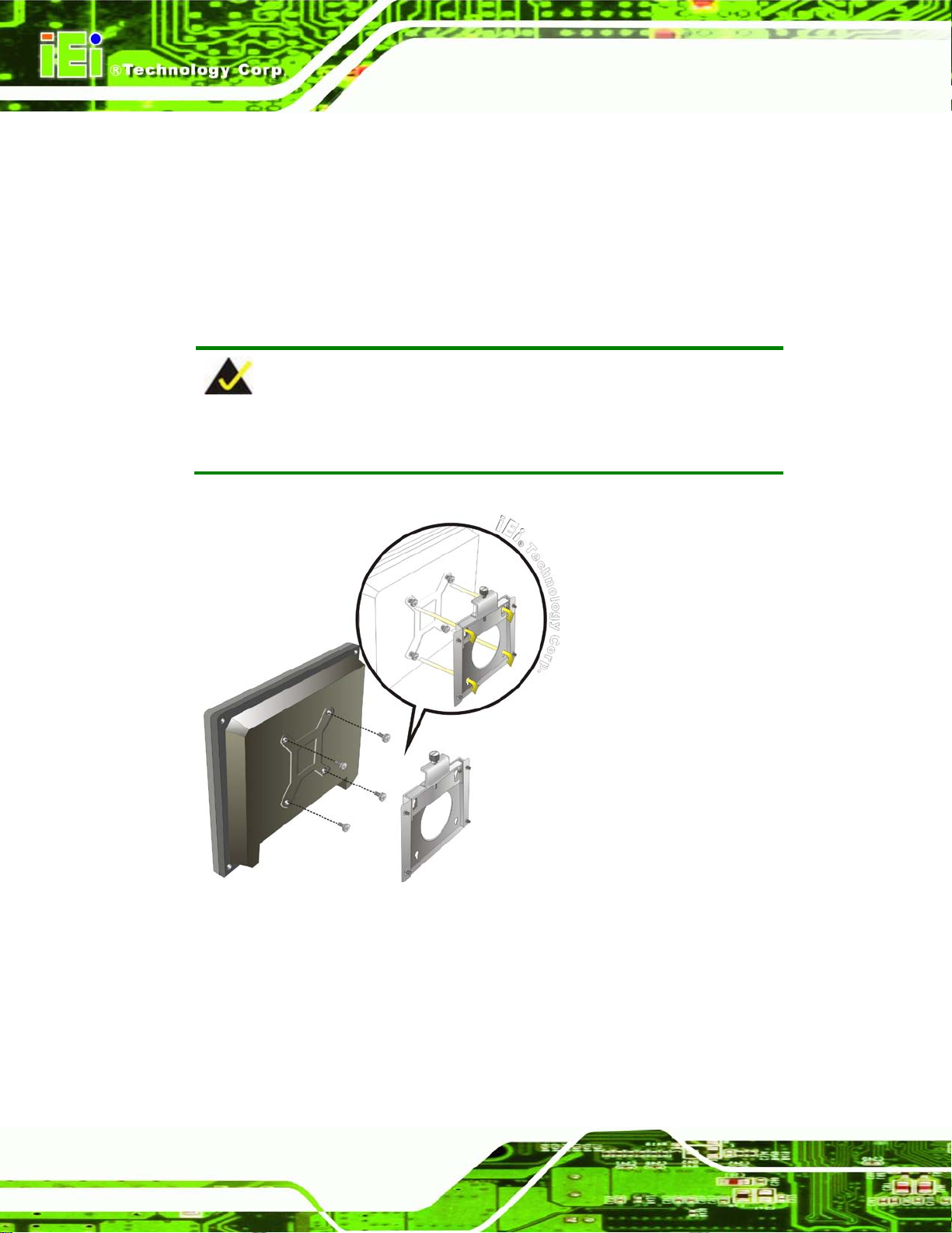
Step 3: Align the panel mounting bracket screw holes with the VESA mounting holes on
the rear of the panel PC.
Step 4: Secure the two panel mounting brackets to the rear of the panel PC by inserting
the four retention screws into the VESA mounting holes (Figure 4-13
Step 5: Insert the panel mounting clamps into the holes of the panel mounting brackets
(Figure 4-13
AFL2-W07A-N26.
Step 6: Tighten the screws that pass through the panel mounting clamps until the plastic
caps at the front of all the screws are firmly secured to the panel.
Step 7: Install the covers into the panel mounting bracket. Each mounting bracket
includes two side covers and one top cover (Figure 4-13
). There are a total of 4 panel mounting clamps for
).
).
Figure 4-13: Tighten the Panel Mounting Clamp Screws
Page 51

AFL2-W07A-N26
Page 35
4.11.3 Stand Mounting
To mount the AFL2-W07A-N26 using the stand mounting kit, please follow the steps
below.
Step 1: Locate the screw holes on the rear of the AFL2-W07A-N26. This is where the
bracket will be attached. (Figure 4-14)
Figure 4-14: Mounting screw location
Step 2: Align the bracket with the screw holes.
Step 3: To secure the bracket to the AFL2-W07A-N26, insert the retention screws into
the screw holes and tighten them. Ste p 0:
4.12 External Peripheral Device Connection
The following external peripheral devices can be connected to the external peripheral
interface connectors.
Audio devices
Display devices
RJ-45 Ethernet cable connector
Serial port devices
Page 52

AFL2-W07A-N26
Page 36
USB devices
To install these devices, connect the corresponding cable connector from the actual
device to the corresponding AFL2-W07A-N26 external peripheral interface connector
making sure the pins are properly aligned.
4.12.1 Audio Connection
The audio jack on the external audio connector enables the AFL2-W07A-N26 to be
connected to a stereo sound setup. To install the audio devices, follow the steps below.
Step 1: Identify the audio plugs. The plugs on your home theater system or speakers
may not match the colors on the rear panel. If audio plugs are plugged into the
wrong jacks, sound quality will be very bad.
Step 2: Plug the audio plug into the audio jack. Plug the audio plug into the audio
jack. If the plug on your speakers is different, an adapter will need to be used to
plug them into the audio jack. The audio jack on the AFL2-W07A-N26 is a
line-out port which connects to a headphone or a speaker.
Figure 4-15: Audio Connector
Step 3: Check audio clarity. Check that the sound is coming through the right speakers
by adjusting the balance front to rear and left to right.
Page 53

AFL2-W07A-N26
Page 37
4.12.2 Dis play De vice Connection
The DisplayPort connector transmits a digital signal to compatible DisplayPort display
devices such as a TV or computer screen. To connect the DisplayPort cable to the
AFL2-W07A-N26, follow the steps below.
Step 8: Locate the DisplayPort connector. The location is shown in Chapter 1.
Step 9: Align the connector. Align the DisplayPort connec t or w ith the DisplayPort port.
Make sure the orientation of the connector is correct.
Figure 4-16: DisplayPort Connection
Step 10: Insert the DisplayPort connector. Gently insert the DisplayPort connector. The
connector should engage with a gentle push. If the connector does not insert
easily, check again that the connector is aligned correctly , and that the connector
is being inserted with the right way up.
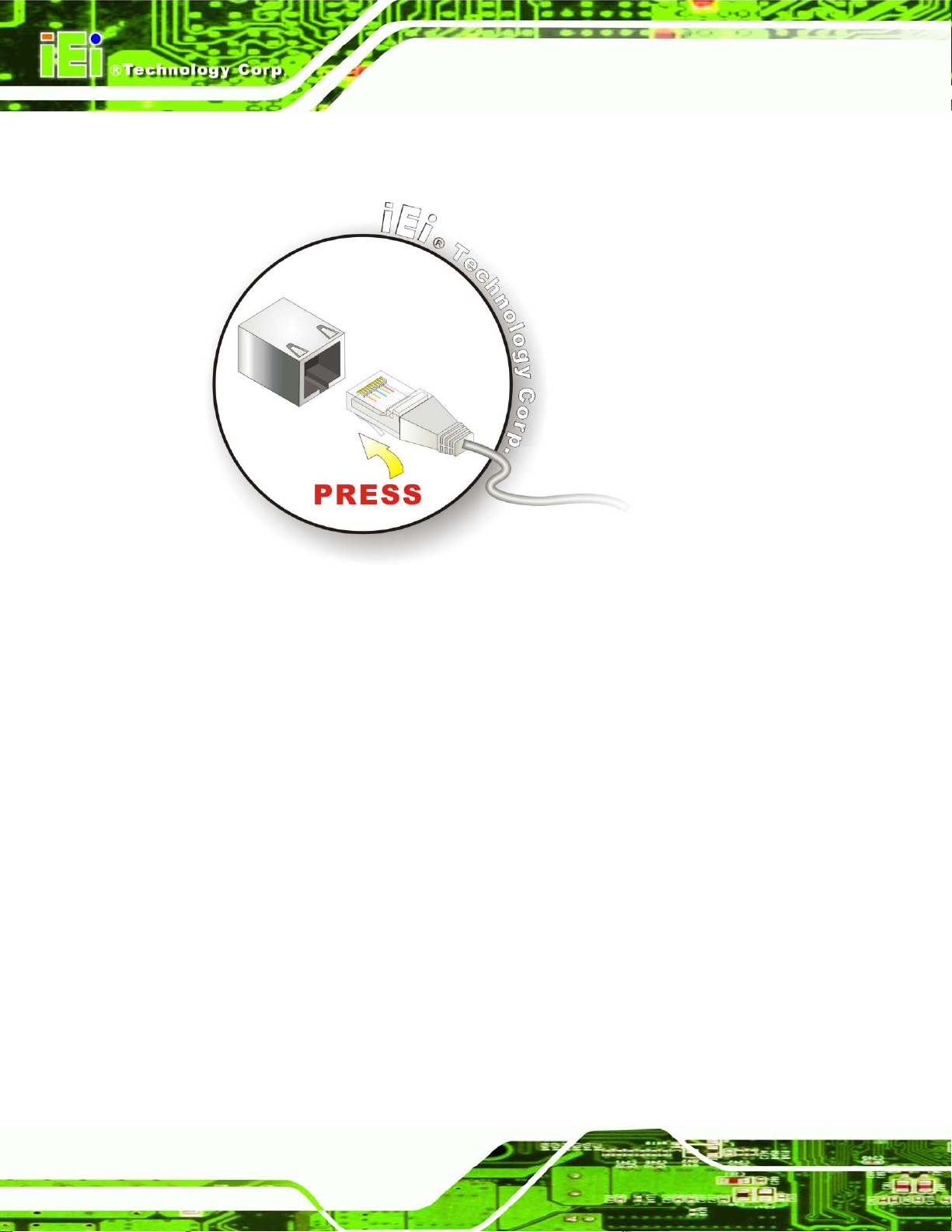
4.12.3 LAN Connection
There is one external RJ-45 LAN connector. T he RJ-45 connect or enables conn ection to
an external network. T o connect a LAN cab le with an RJ -45 connector, ple ase follow the
instructions below.
Step 1: Locate the RJ-45 connector. The location of the LAN connector is shown in
Chapter 1.
Page 54
AFL2-W07A-N26
Page 38
Step 11: Align the connector . Align the RJ-45 connector on the LAN cable with the
RJ-45 connector on the AFL2-W07A-N26. See Figure 4-17.
Figure 4-17: LAN Connection
Step 12: Insert the LAN cable RJ-45 connector. Once aligned, gently insert the LAN
cable RJ-45 connector into the external interface.
4.12.4 Serial Device Connection
There is one external RS-232 DB-9 connector and one R S-422/485 RJ-11 connector for
serial device connection. Follow the steps below to connect a serial device to the
AFL2-W07A-N26.
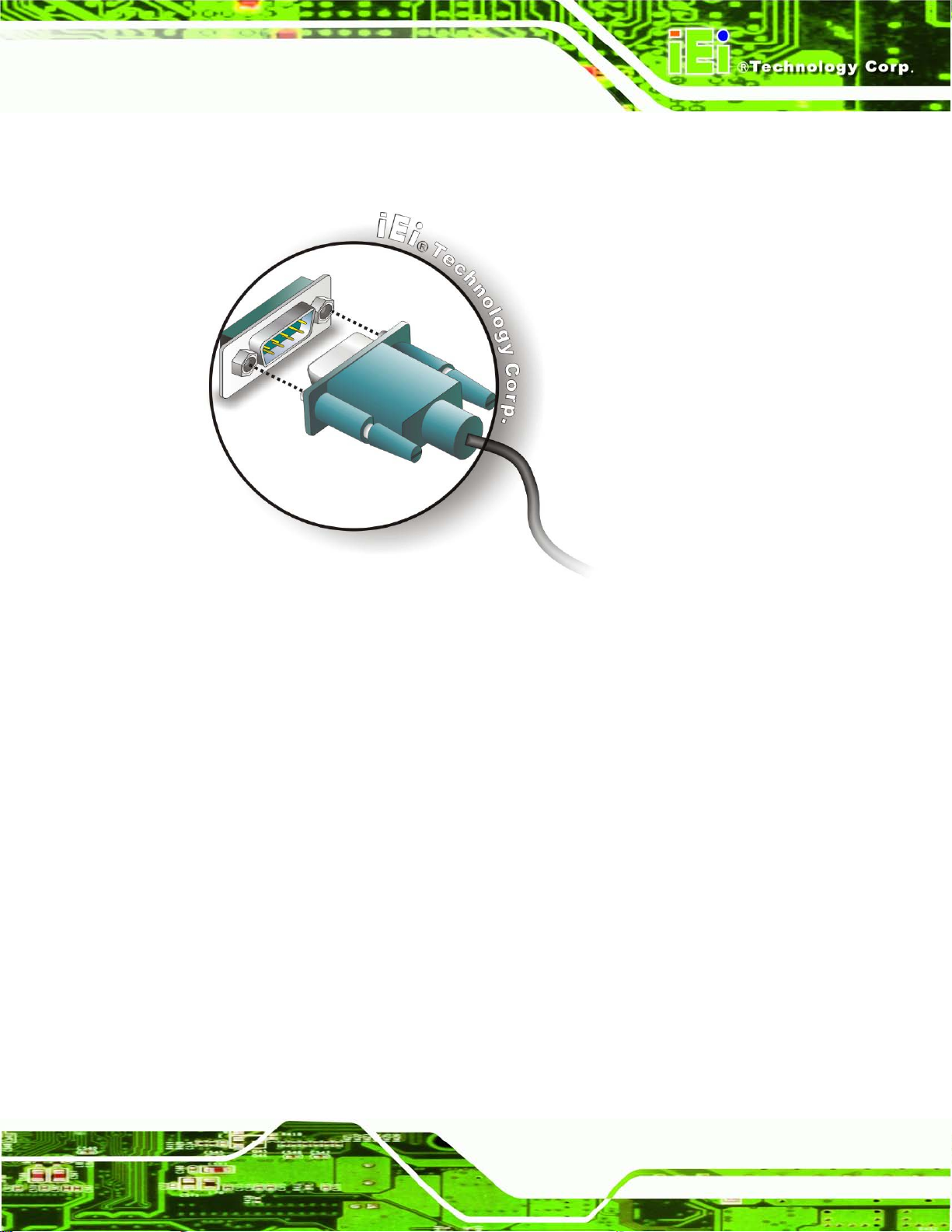
4.12.4.1 DB-9 S erial Port Connection
Follow the steps below to connect a serial device to the DB-9 connector of the
AFL2-W07A-N26 panel PC.
Step 13: Locate the DB-9 connector. The location of the DB-9 connector is shown in
Chapter 1.
Page 55
AFL2-W07A-N26
Page 39
Step 14: Insert the serial connect o r . Insert the DB-9 connector of a serial device into
the DB-9 connector on the bottom panel. See Figure 4-18.
Figure 4-18: DB-9 Serial Port Connector
Step 15: Secure the connector. Secure the serial device connector to the external
interface by tightening the two retention screws on either side of the connector.
4.12.4.2 RJ-11 Serial Port Connection
Follow the steps below to c onnec t a serial device to the RJ-11 serial port connector of the
AFL2-W07A-N26 panel PC.
Step 1: Locate the RJ-11 serial port. The location of the RJ-11 serial port is shown in
Chapter 1.
Step 2: Connect the RJ-11 to DB-9 COM port cable to the panel PC. Insert the RJ-11
connector end of cable into the RJ-11 serial port. See Figure 4-19.
Step 3: Connect the serial device. Connect a serial device to the DB-9 connector end
Step 0:
of the cable. See Figure 4-19.
Page 56

AFL2-W07A-N26
Page 40
Figure 4-19: RJ-11 Serial Port Connector
Step 4: Secure the connector. Secure the serial device connector to the external
interface by tightening the two retention screws on either side of the connector .
The DB-9 connector pinouts are listed below.
PIN NO. RS-422 RS-485
1 RX+ 2 RX- 3 TX+ D+
4 TX- D5 - 6 - 7 - 8 - 9 - -
4.12.5 USB De vice Connection
Step 0:
NOTE:
User must install the USB 3.0 driver before connecting a USB device to
the system or else the system may not recognize the connected
device.
Page 57

AFL2-W07A-N26
Page 41
4.12.5 USB De vice Connection
NOTE:
User must install the USB 3.0 driver before connecting a USB device to
the system or else the system may not recognize the connected
device.
There are two USB 2.0 c on nec tors and two USB 3.0 connector s on the AFL2-W07A-N26.
To connect a USB device, please follow the instructions below.
Step 1: Locate the USB connectors. The locations of the USB connectors are shown
in Chapter 1.
Step 2: Align the connectors. Align the USB device connector with one of the
connectors on the bottom panel. See Figure 4-21.
Figure 4-21: USB Device Connection
Page 58

AFL2-W07A-N26
Page 42
Step 3: Insert the device connector. Once align ed, ge ntly insert the USB device
connector into the onboard connector. Step 0:
Page 59
AFL2-W07A-N26
Page 43
Chapter
5
5 System Motherboard
Page 60

AFL2-W07A-N26
Page 44
5.1 Overview
This chapter details all the jumpers and connectors of the system motherboard.
5.1.1 Layout
The figures below sho w all the connectors and jumpers of the system motherboar d. The
Pin 1 locations of the on-board connectors are also indicated in the diagram below.
Figure 5-1: System Motherboard (front)
Page 61
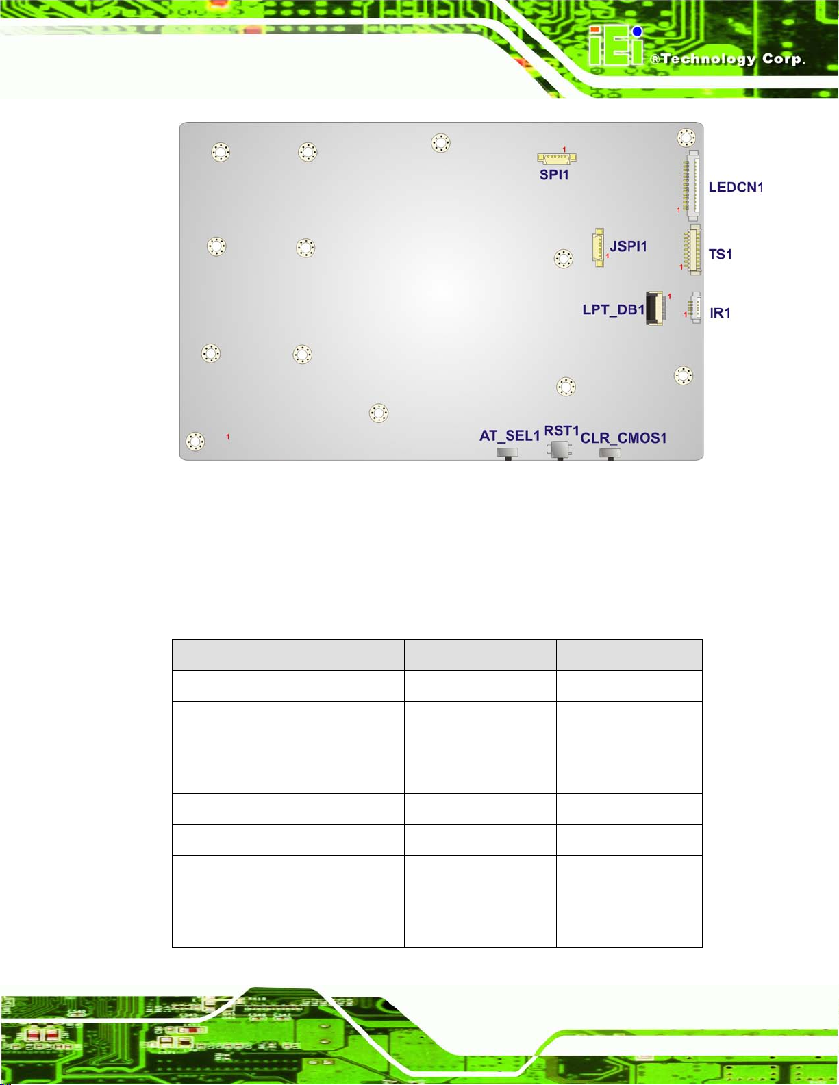
AFL2-W07A-N26
Page 45
Figure 5-2: System Motherboard (rear)
5.2 Internal Peripheral Connectors
The table belo w shows a l ist of the intern al perip hera l interfac e connec tors on the system
motherboard. Pinouts of these connectors can be found in the following sections.
Connector Type Label
Audio connector 10-pin header AUDIO1
Auto-dimming connector 5-pin wafer IR1
Battery connector 2-pin wafer BAT1
BIOS programming connector 6-pin wafer SPI1
Bluetooth connector 4-pin wafer BLUETOOTH1
DDR3 SO-DIMM slot DDR3 SO-DIMM slot DIMM1
Debug port connector 9-pin wafer LPC_DEBUG1
EC firmware connector 6-pin wafer JSPI1
Hot key connector 9-pin wafer HOT_KEY1
Page 62
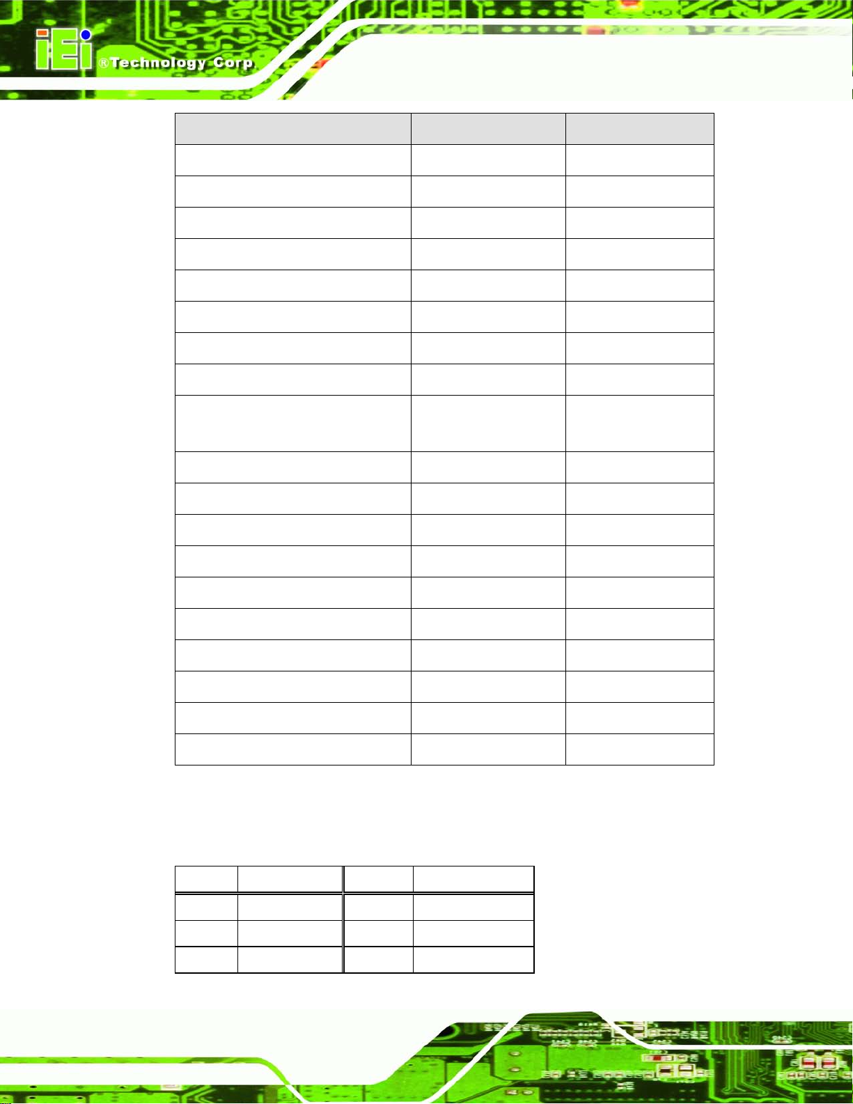
AFL2-W07A-N26
Page 46
Connector Type Label
K type connector 2-pin wafer K_TYPE1, K_TYPE2
LCD inverter connector 5-pin waf er INVERTER1
LCD LVDS connector 20-pin wafer JR1
LED connector 14-pin wafer LEDCN1
LPT connector 20-pin wafer LPT_DB1
Micro SD connector 5-pin wafer MICRO_SD1
Mini USB connector 4-pin waf er MINI_USB1
Microphone connector 4-pin wafer WEBCAM_DMIC1
PCIe mini card slot PCIe mini card slot MINI_PCIE1,
MINI_PCIE2
Power button connector 2-pin wafer PW_BT1
RFID USB connector 4-pin wafer RFID1
Speaker connector 4-pin wafer AMP_SPKR1
Touch panel connector 9-pin waf er TS1
Touch panel connector 4-pin waf er CAP_TS1
VGA connector 10-pin header VGA1
Webcam connector 4-pin wafer CAMERA1
AT/ATX mode select switch AT_SEL1
Clear CMOS switch CLR_COMS1
Reset button button RST1
Table 5-1: Peripheral Interface Connectors
5.2.1 Au dio Connector (AUDIO1)
PIN NO. DESCRIPTION PIN NO. DESCRIPTION
1 LINE_OUTR 2 LMIC1-L
3 AMP_INR 4 LMIC1-R
5 LINE_OUTL 6 FRONT_JD
Page 63
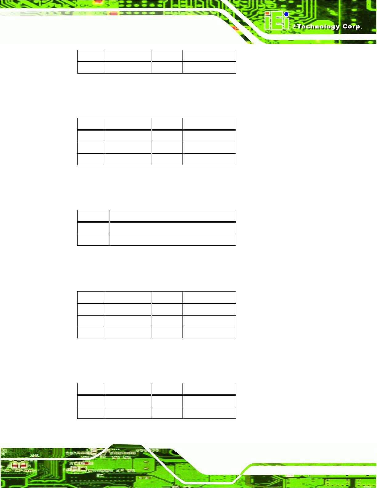
AFL2-W07A-N26
Page 47
7 FRONT_JD 8 MIC1_JD
9 GND_AUDIO 10 GND_AUDIO
Table 5-2: Audio Connector Pinouts (AUDIO1)
5.2.2 Au to-dimming Connector (IR1)
PIN NO. DESCRIPTION PIN NO. DESCRIPTION
1 VCC 2 IRRX
3 SMB_CLK_AD 4 SMB_DAT_AD
5 GND
Table 5-3: Auto-dimming Connector Pinouts (IR1)
5.2.3 Battery Connector (BAT1)
PIN NO. DESCRIPTION
1
2 GND
Table 5-4: Battery Connector Pinouts (BAT1)
VCC
5.2.4 BIOS Programming Connector (SPI1)
PIN NO. DESCRIPTION PIN NO. DESCRIPTION
1 SPI_VCC 2 SPI_2N_CS#
3 SPI_2N_MISO 4 SPI_2N_CLK
5 SPI_2N_MOSI 6 GND
Table 5-5: BIOS Programming Connector Pinouts (SPI1)
5.2.5 Bluetooth Connector (BLUETOOTH1)
PIN NO. DESCRIPTION PIN NO. DESCRIPTION
1 VCC 2 DATA7_N
3 DATA7_P 4 GND
Table 5-6: Bluetooth Connector Pinouts (BLUETOOTH1)
Page 64

AFL2-W07A-N26
Page 48
5.2.6 Debug Port Connector (LPC_DEBUG1)
PIN NO. DESCRIPTION PIN NO. DESCRIPTION
1 PLT_RST# 2 LPC_DEBUG_CLK
3 GND 4 LPC_AD3
5 LPC_AD2 6 LPC_AD1
7 LPC_AD0 8 LPC_FRAME#
9 VCC3
Table 5-7: Debug Port Connector Pinouts (LPC_DEBUG1)
5.2.7 EC Firmware Connector (JSPI1)
PIN NO. DESCRIPTION PIN NO. DESCRIPTION
1 SPI_VCC 2 FSCE#_S
3 FMISO_S 4 FSCK_S
5 FMOSI_S 6 GND
Table 5-8: EC Firmware Connector Pinouts (JSPI1)
5.2.8 Hot Key Connector (HOT_KEY1)
PIN NO. DESCRIPTION PIN NO. DESCRIPTION
1 EC_KSI1 2 EC_KSO5
3 EC_KSO4 4 EC_KSO3
5 EC_KSO2 6 EC_KSO1
7 EC_KSO0 8 GND
9 GND
Table 5-9: Hot Key Connector Pinouts (HOT_KEY1)
5.2.9 K Type Connector (K_TYPE1, K_TYPE2)
PIN NO. DESCRIPTION PIN NO. DESCRIPTION
1
D1+/D2+
2 D1-/D2-
Table 5-10: K Type Connector Pinouts (K_TYPE1, K_TYPE2)
Page 65

AFL2-W07A-N26
Page 49
5.2.10 LCD Inverter Connector (INVERTER1)
PIN NO. DESCRIPTION PIN NO. DESCRIPTION
1 BRIGHTNESS 2 DATA7_N
3 BKL_POWER 4 GND
5 ENABKL
Table 5-11: LCD Inverter Connector Pinouts (INVERTER1)
5.2.11 LCD LVDS c onnector (JR1)
PIN NO. DESCRIPTION PIN NO. DESCRIPTION
1 GND 2 GND
3 LVDSA_DATA0_R 4 LVDSA_DATA#0_R
5 LVDSA_DATA1_R 6 LVDSA_DATA#1_R
7 LVDSA_DATA2_R 8 LVDSA_DATA#2_R
9 LVDSA_CLK_R 10 LVDSA_CLK#_R
11 LVDSA_DATA3_R 12 LVDSA_DATA#3_R
13 GND 14 GND
15 NC 16 NC
17 VCC3 18 VCC_LCD
19 VCC_LCD 20 VCC_LCD
Table 5-12: LCD LVDS connector Pinouts (JR1)
5.2.12 LED Connector (LEDCN1)
PIN NO. DESCRIPTION PIN NO. DESCRIPTION
1 CPU_LEDR# 2 CPU_LEDB#
3 AT_LED# 4 ATX_LED#
5 PWR_LED# 6 PWR_YLED#
7 AD_LED# 8 WIFI_LED#
9 RF_LED# 10 BT_LED#
11 VCC3A_EC 12 VCC3
13 GND 14 GND
Page 66
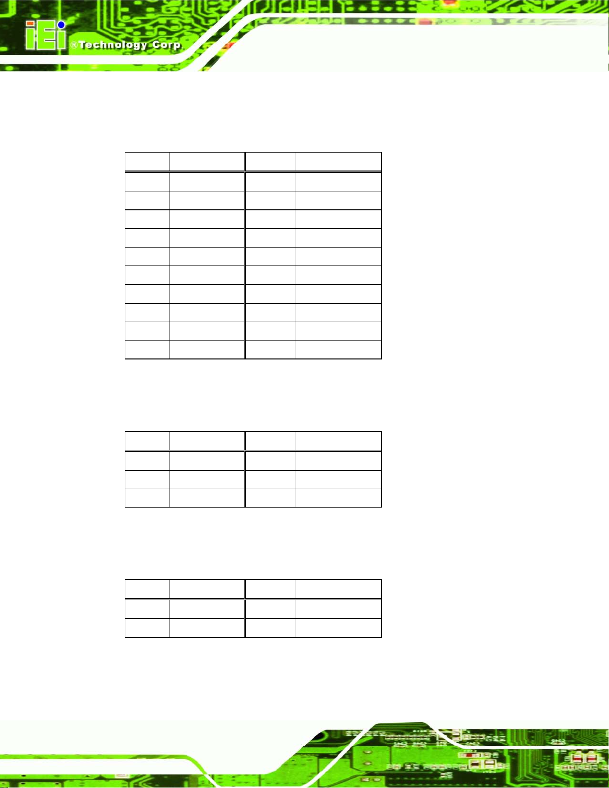
AFL2-W07A-N26
Page 50
Table 5-13: LED Connector Pinouts (LEDCN1)
5.2.13 LPT C onnector (LPT_DB1)
PIN NO. DESCRIPTION PIN NO. DESCRIPTION
1 EC_KSI0 2 EC_KSO0
3 EC_KSO1 4 EC_KSO2
5 EC_KSO3 6 EC_KSO4
7 EC_KSO5 8 EC_KSO6
9 EC_KSO7 10 EC_KSO8
11 EC_KSO9 12 EC_KSO10
13 EC_KSO12 14 EC_KSI1
15 EC_KSO11 16 EC_KSI2
17 EC_KSI3 18 GND
19 GND 20 GND
Table 5-14: LPT Connector Pinouts ( LPT_DB1)
5.2.14 Micro SD Connector (MICRO_SD1)
PIN NO. DESCRIPTION PIN NO. DESCRIPTION
1 VCC_MSD 2 DATA3_N
3 DATA3_P 4 GND
5 VCC3
Table 5-15: Micro SD Connector Pinouts (MICRO_SD1)
5.2.15 Mini USB Connector (MINI_US B1)
PIN NO. DESCRIPTION PIN NO. DESCRIPTION
1 VCC_NIMIUSB 2 DATA2_N
3 DATA2_P 4 GND
Table 5-16: Mini USB Connector Pinouts (MINI_USB1)
Page 67
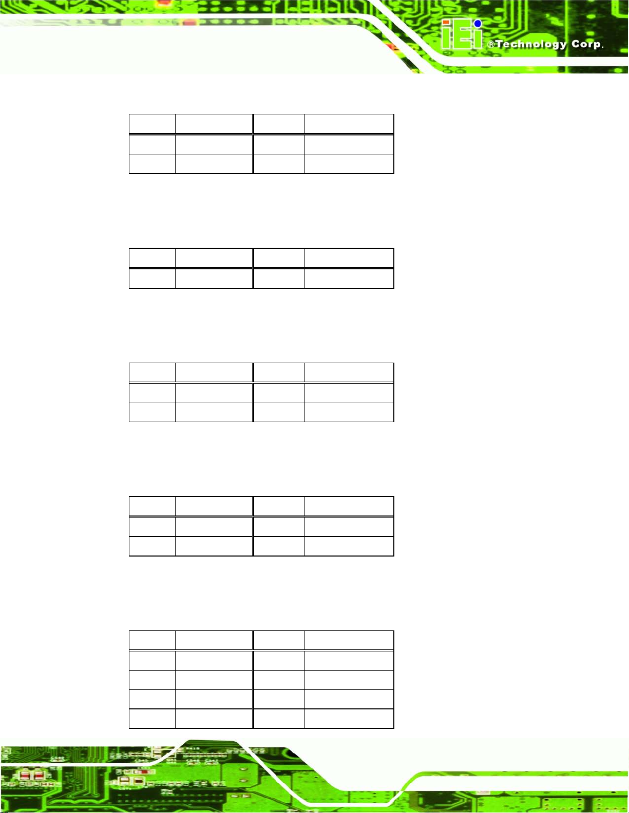
AFL2-W07A-N26
Page 51
5.2.16 Microphone Connector (WEBCAM_DMIC1)
PIN NO. DESCRIPTION PIN NO. DESCRIPTION
1 DMIC_CLK_R 2 DMIC_DATA_R
3 VCC 4 GND
Table 5-17: Microphone Connector Pinouts (WEBCAM_DMIC1)
5.2.17 Power Button Connector (PW_BT1)
PIN NO. DESCRIPTION PIN NO. DESCRIPTION
1 PWRBTN_SW# 2 GND
Table 5-18: Power Button Connector Pinouts (PW_BT1)
5.2.18 RF ID USB Connector (RFID1)
PIN NO. DESCRIPTION PIN NO. DESCRIPTION
1 VCC 2 DATA5_N
3 DATA5_P 4 GND
Table 5-19: RFID USB Connector Pinouts (RFID1)
5.2.19 Speaker Connector (AMP _SPKR1)
PIN NO. DESCRIPTION PIN NO. DESCRIPTION
1 SPK_OUT_P_L 2 SPK_OUT_N_L
3 SPK_OUT_N_R 4 SPK_OUT_P_R
Table 5-20: Speaker Connector Pinouts (AMP_SPKR1)
5.2.20 Touch Panel Connector (TS1)
PIN NO. DESCRIPTION PIN NO. DESCRIPTION
1 X+ 2 X3 Y+ 4 SENSE
5 X+ 6 X7 Y+ 8 Y-
Page 68

AFL2-W07A-N26
Page 52
9 GND
Table 5-21: Touch Panel Connector Pinouts (TS1)
5.2.21 Touch Panel Connector (CAP_TS1)
PIN NO. DESCRIPTION PIN NO. DESCRIPTION
1 VCC 2 -DATA4
3 +DATA4 4 GND
Table 5-22: Touch Panel Connector Pinouts (CAP_TS1)
5.2.22 VGA Connector (VGA1)
PIN NO. DESCRIPTION PIN NO. DESCRIPTION
1 L_RED 2 DDC_DATA
3 L_GREEN 4 DDC_CLK
5 L_BLUE 6 D_GND
7 HSYNC 8 GND
9 VSYNC 10 GND
Table 5-23: VGA Connector Pinouts (VGA1)
5.2.23 Webcam Connector (CAMERA1)
PIN NO. DESCRIPTION PIN NO. DESCRIPTION
1 VCC 2 DATA6_N
3 DATA6_P 4 GND
Table 5-24: Webcam Connector Pinouts (CAMERA1)
Page 69

AFL2-W07A-N26
Page 53
5.3 External Interface Panel Connectors
The figures below show all the external interface panel connectors on the system
motherboard.
Figure 5-3: External Interface Panel Connectors
The table below shows a list of the external interface panel c onnectors on the system
motherboard. Pinouts of these connectors can be found in the following sections.
Connector Type Label
Display port connector Display port DISPLAY_PORT1
Ethernet connector RJ-45 LAN1
Power connector Power jack DC_IN1
RS-232 serial port connector DB-9 COM1
RS-232 serial port connector RJ11 COM2
USB 2.0 connectors USB 2.0 port USB1
USB 3.0 connectors USB 3.0 port USB3_1
Table 5-25: Rear Panel Connectors
Page 70

AFL2-W07A-N26
Page 54
5.3.1 Dis p lay Por t C onnector (DISPLAY_PORT1)
PIN NO. DESCRIPTION PIN NO. DESCRIPTION
1 C_DDI0_DP_DATA0 2 GND
3 C_DDI0_DP_DATA0# 4 C_DDI0_DP_DATA1
5 GND 6 C_DDI0_DP_DATA1#
7 C_DDI0_DP_DATA2 8 GND
9 C_DDI0_DP_DATA2# 10 C_DDI0_DP_DATA3
11 GND 12 C_DDI0_DP_DATA3#
13 GND 14 GND
15 C_DDI0_DP_AUXP 16 GND
17 C_DDI0_DP_AUXN 18 C_DDI0_DP_HPD
19 GND 20 VCC
21 GND 22 GND
23 GND 24 GND
Table 5-26: Display Port Connector Pinouts (DISPLAY_PORT1)
5.3.2 Ethernet Connector (LAN1)
PIN NO. DESCRIPTION PIN NO. DESCRIPTION
R1
R3
R5
R7
R9
11
L1
L3
LAN2_MDI0+
LAN2_MDI1+
NC
LAN2_MDI2+
LAN2_MDI3+
LAN2_GND
LAN2_LINK100
LAN2_ACT-1
R2
R4
R6
R8
R10
11
L2
L4
Table 5-27: Ethernet Connector Pinouts (LAN1)
LAN2_MDI0LAN2_MDI1NV
LAN2_MDI2LAN2_MDI3LAN2_GND
LAN2_LINK1000
VCC PU
Page 71

AFL2-W07A-N26
Page 55
5.3.3 Power Connector (DC_IN1)
PIN NO. DESCRIPTION PIN NO. DESCRIPTION
VCC
1
3 GND
Table 5-28: Power Connector Pinouts (DC_IN1)
5.3.4 RS-232 Serial Po rts (COM1)
PIN NO. DESCRIPTION PIN NO. DESCRIPTION
1 NDCD1 2 NRX1
3 NTX1 4 NDTR1
5 GND 6 NDSR1
2 GND
7 NRTS1 8 NCTS1
9 NRI1
Table 5-29: RS-232 Serial Po rts Pinouts (COM1)
5.3.5 RS-422/485 Serial Port (C OM2)
PIN NO. DESCRIPTION PIN NO. DESCRIPTION
1 RXD485+ 2 RXD485#
3 TXD485+ 4 TXD485#
5 GND
Table 5-30: RS-422/485 Se rial Port Pinouts (COM2)
5.3.6 USB 2.0 Connec tors (USB1)
PIN NO. DESCRIPTION PIN NO. DESCRIPTION
1 VCC 2 DATA0_N
3 DATA0_P 4 GND
5 VCC 6 DATA1_N
7 DATA1_P 8 GND
Table 5-31: USB 2.0 Connectors Pinouts (USB1)
Page 72

AFL2-W07A-N26
Page 56
5.3.7 USB 3.0 Connectors (USB3_1)
PIN NO. DESCRIPTION PIN NO. DESCRIPTION
1 VCC 2 USB2P0_DM2_L
3 USB2P0_DP2_L 4 GND
5 USB3P0_RXDN2 6 USB3P0_RXDP2
7 GND 8 USB3P0_TXDN2_C
9 USB3P0_TXDP2_C 10 VCC
11 USB2P0_DM1_L 12 USB2P0_DP1_L
13 GND 14 USB3P0_RXDN1
15 USB3P0_RXDP1 16 GND
17 USB3P0_TXDN1_C 18 USB3P0_TXDP1_C
Table 5-32: USB 3.0 Connector Pinouts (USB3_1)
Page 73

AFL2-W07A-N26
Page 57
Chapter
6
6 System Maintenanc e
Page 74
AFL2-W07A-N26
Page 58
may result in permanent damage to the
6.1 S ystem Maintenance Introduction
If the components of the AFL2-W07A-N26 fai l they must be replaced. Com ponents that
can be replaced include:
SO-DIMM module
WLAN module
Please contact the system reseller or vendor to purchase the replacem ent parts. Back
cover removal instructions for the AFL2-W07A-N26 are described below.
6.2 Anti-static Precautions
WARNING:
Failure to take ESD precautions during the maintenance of the
AFL2-W07A-N26
AFL2-W07A-N26 and severe injury to the user.
Electrostatic discharge (ESD) can cause serious damage to electronic components,
including the AFL2-W07A-N26. Dry climates are especially susceptible to ESD. It is
therefore critical that when ever the AFL2-W07A-N26 i s accessed internall y, or any other
electrical component is handled, the fol lowing anti-static pr ecautions are strictl y adhered
to.
Wear an anti-static wristband: - Wearing a simple anti-static wristband can
help to prevent ESD from damaging the board.
Self-grounding: - Before handling the board touch any grounded conducting
material. During the time the board is handled, frequently touch any
conducting materials that are connected to the ground.
Use an anti-static pad: - When configuring the AFL2-W07A-N26, place it on
an antic-static pad. This reduces the possibility of ESD damaging the
AFL2-W07A-N26.
Only handle the edges of the PCB: - When handling the PCB, hold the PCB
by the edges.
Page 75
AFL2-W07A-N26
Page 59
ll crack the plastic frame.
6.3 Turn off the Power
WARNING:
Failing to turn off the s ystem before opening it can cause permanent
damage to the system and serious or fatal injury to the user.
Before any maintenance procedures are carried out on the system, make sure the system
is turned off.
To power off the system, follow the steps below:
Step 1: Locate the Function and Brightness Up function keys. See Section 1.2.1.1.
Step 2: Hold down the Function and Brightness Up buttons for six seconds to power off
the system. Ste p 0:
6.4 Opening the System
6.4.1 Removing the Back Cover
WARNING:
Over-tightening back cover screws wi
Maximum torque for cover screws is 5 kg-cm (0.36 lb-ft/0.49 Nm).
T o access the AFL2-W07A-N26 internally the back cover must be removed. To remove the
back cover, please follow the steps below.
Step 1: Follow all anti-static procedures. See Section 6.2.
Step 2: Turn off the power. See Section 6.3.
Step 3: Remove a total of ten (10) retention screws from the back cover (Figure 6-1).
Page 76

AFL2-W07A-N26
Page 60
Figure 6-1: Back Cover Retention Screws
Step 4: Carefully separate the back cover from the chassis and lift the cover clear of the
device
6.4.2 Removing the Internal Aluminum Cover
To remove the internal aluminum cover, follow the steps below.
Step 1: Remove the five (5) retention screws securing the internal aluminum cover to
the chassis (Figure 5-2).
Page 77
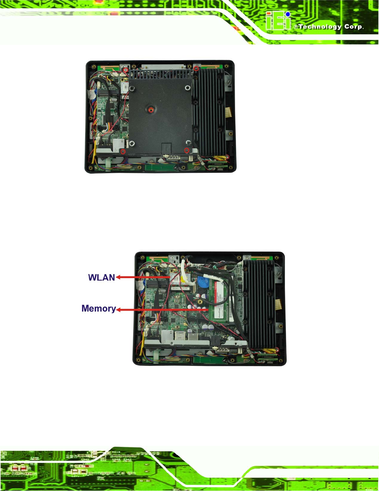
AFL2-W07A-N26
Page 61
Figure 6-2: Internal Cover Retention Screws
Step 2: Lift the aluminum cover off the AFL2-W07A-N26.
Step 3: The internal parts will all be viewable.
Figure 6-3: Internal Components
Page 78

AFL2-W07A-N26
Page 62
6.5 Repla cing Components
6.5.1 Me mory Module Replacement
The flat bezel panel PC is preinstalled with two 2.0 GB DDR3 memory module. If the
memory module fails, follow the instructions below to replace the memory module.
Step 1: Follow all anti-static procedures. See Section 6.2.
Step 4: Turn off the power. See Section 6.3.
Step 2: Remove the back cover. See Section 6.4.1 above.
Step 3: Remove the internal aluminum back cover. See Section 6.4.2 above.
Step 4: Locate the DDR3 SO-DIMM on the motherboard.
Step 5: Remove the DDR3 memory module by pulling both the spring retainer clips
outward from the socket.
Step 6: Grasp the DDR3 memory module by the edges and carefully pull it out of the
socket.
Step 7: Install the new DDR3 memory m odule b y pushing it into the socket at an angle
(Figure 6-4).
Step 8: Gently pull the spring retainer clips of the SO-DIMM socket out and push the
rear of the DDR memory module down (Figure 6-4).
Step 9: Release the spring retainer clips on the SO-DIMM socket. They clip into place
and secure the DDR memory module in the socket.
Page 79
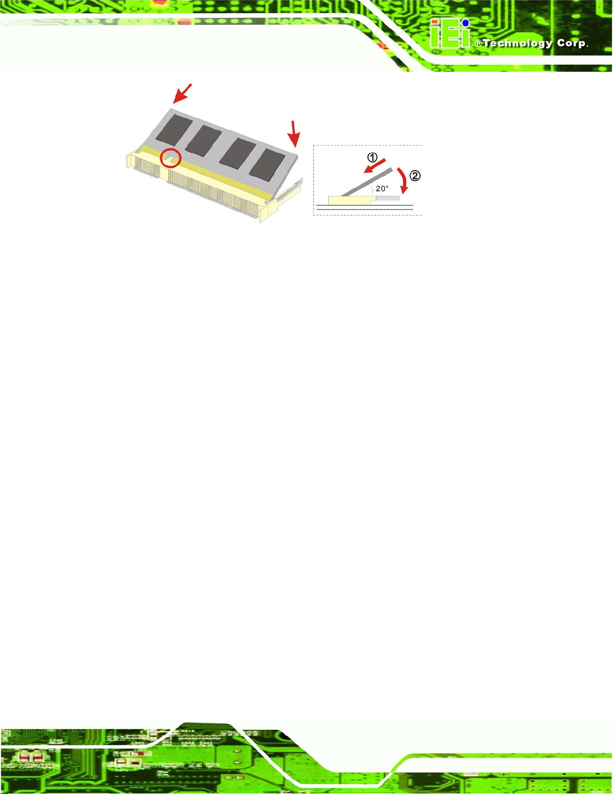
AFL2-W07A-N26
Page 63
Figure 6-4: DDR SO-DIMM Module Installation
Step 10: Replace the internal aluminum cover and secure it to the chassis using five (5)
retention screws.
Step 11: Replace the back cover and secure it using ten (10) previously removed
retention screws. Ste p 0:
6.5.2 WLAN Card Replacement
The AFL2-W07A-N26 has one WLAN card slot. To replace the W LAN card, follow the
instructions below.
Step 1: Follow all anti-static procedures. See Section 6.2.
Step 2: Turn off the power. Se e Section 6.3.
Step 3: Remove the back cover. See Section 6.4.1 above.
Step 4: Remove the internal back cover. See Section 6.4.2 above.
Step 5: Locate the WLAN card.
Step 6: Disconnect the main and auxiliar y antenn as on the WLAN m odul e and push the
two spring clips in to release the WLAN card (Figure 6-5).
Page 80

AFL2-W07A-N26
Page 64
Figure 6-5: Releasing the WLAN Card
Step 7: Grasp the WLAN card by the edges and carefully pull it out of the socket (Figure
6-6).
Figure 6-6: Removing the WLAN card
Step 8: Install a new WLAN card by inserting the card into the slot at an angle
Page 81

AFL2-W07A-N26
Page 65
Step 9: Push the WLAN card down until the spring retainer clips lock into place.
Step 10: Connect the main (1) and auxiliary (2) antennas. The main antenna is indicated
with a strip of black electrical tape. See Figure 6-7.
NOTE:
To ensure the WLAN module functions correctly, please make sure the
WLAN antennas are attached in the proper configuration.
Figure 6-7: Attaching the Antennas
Step 11: Replace the internal cover and secure it to the chassis using the previously
removed retention screws.
Step 12: Replace the back cover and secure it using the previously removed retention
screws.
Page 82

AFL2-W07A-N26
Page 66
6.6 Reinstalling the Covers
WARNING:
Failing to reinsta ll the covers may resu lt in permanent dam age to the
system. Please make sure all coverings are properly installed.
When maintenance procedures are complete, please make sure all the covers are
replaced, including the following:
Aluminum internal cover
Plastic back cover
Page 83

AFL2-W07A-N26
Page 67
Chapter
7
7 BIOS S etup
Page 84

AFL2-W07A-N26
Page 68
7.1 Introduction
A licensed copy of the BIOS is preprogrammed into the ROM BIOS. The BIOS setup
program allows users to modify the basic s ystem configuratio n. This chapter describes
how to access the BIOS setup program and the configuration options that may be
changed.
7.1.1 Starting Setup
The UEFI BIOS is activated when t he computer is turned o n. The setup program can be
activated in one of two ways.
1. Press the DEL or F2 key as soon as the system is turned on or
2. Press the DEL or F2 key when the “Press DEL or F2 to enter
SETUP” message appears on the screen. 0.
If the message disappears bef or e the DEL or F2 key is pres sed, r es tart the c omputer and
try again.
7.1.2 Using Setup
Use the arrow keys to highlight items, press ENTER to select, use the PageUp and
PageDown keys to c hange entries, press F1 f or help and press E
keys are shown in the following table.
Key Function
Up arrow Move to the item above
Down arrow Move to the item below
Left arrow Move to the item on the left hand side
Right arrow Move to the item on the right hand side
+ Increase the numeric value or make changes
- Decrease the numeric value or make changes
SC to quit. Navigation
F1 key General help, only for S t atus Page Setup Menu and Option
Page Setup Menu
Page 85

AFL2-W07A-N26
Page 69
F2 key Load previous values.
F3 key Load optimized defaults
F4 key Save changes and Exit BIOS
Esc key Main Menu – Quit and do not save changes into CMOS
Table 7-1: BIOS Navigation Keys
7.1.3 Getting Help
When F1 is pressed a sm all help windo w describing t he appropriate keys to use and the
Status Page Setup Menu and Option Page Setup Menu -Exit current page and return to Main Menu
possible selections for the highlighted item appears. To exit the Help Window press E
the F1 key again.
7.1.4 Unable to Reboot after Configuration Changes
If the computer ca nnot boot after changes to th e system conf iguration are m ade, CMOS
defaults.
7.1.5 BIOS Menu Bar
The menu bar on top of the BIOS screen has the following main items:
Main – Changes the basic system configuration.
Advanced – Changes the advanced system settings.
Chipset – Changes the chipset settings.
Boot – Changes the system boot configuration.
Security – Sets User and Supervisor Passwords.
Save & Exit – Selects exit options and loads default settings
SC or
The following secti ons completely describe the configuration options found in the menu
items at the top of the BIOS screen and listed above.
Page 86

AFL2-W07A-N26
Page 70
Aptio Setup Utility – Copyright (C) 2011 American Megatrends, Inc.
Main
Advanced
Chipset
Boot
Security
Save & Exit
ESC: Exit
Version 2.14.1219. Copyright (C) 2011 American Megatrends, Inc.
7.2 Ma in
The Main BIOS menu (BIOS Menu 1) appears when the BIOS Setup program is entered.
The Main menu gives an overview of the basic system information.
BIOS Information
BIOS Vendor American Megatrends
Core Version 4.6.5.3 0.16
Compliency UEFI 2.3; PI 1.2
Project Version SE19AR13.ROM
Build Date and Time 09/24/2012 11:30:41
iWDD Vendor ICP
iWDD Version SE19ER13.bin
System Date [Fri 10/19/2012]
System Time [14:21:27]
Access Level Administrator
BIOS Menu 1: Main
BIOS Information
The BIOS Information lists a brief summary of the BIOS. The fields in BIOS Information
cannot be changed. The items shown in the system overview include:
Set the Date. Use Tab to
switch between Data
elements.
----------------------
: Select Screen
↑ ↓: Select Item
Enter Select
+/-: Change Opt.
F1: General Help
F2: Previous Values
F3: Optimized Defaults
F4: Save & Exit
BIOS Vendor: Installed BIOS vendor
Core Version: Current BIOS version
Compliency: Current compliant version
Project Version: the board version
Build Date and Time: Date the current BIOS version was made
iWDD Vendor
The iWDD Vendor displays the installed iWDD vendor. The fields in iWDD
Vendor cannot be changed.
Page 87

AFL2-W07A-N26
Page 71
iWDD Ve rs io n
The iWDD Version displays the current iWDD version. The fields in iWDD
Version cannot be changed.
The System Overview field also has two user configurable fields:
System Date [xx/xx/xx]
Use the System Date option to set the s ystem date. Manuall y enter the da y, month and
year.
System Time [xx:xx:xx]
Use the System Time option to set the s ystem time. Manuall y enter the hours, minutes
and seconds.
7.3 Advanced
Use the Advanced menu (BIOS Menu 2) to configure the CPU and peripheral devices
through the following sub-menus:
WARNING:
Setting the wrong values in the sections below m ay cause the s ystem
to malfunction. Mak e sure that the settings m ade are compatible with
the hardware.
Page 88

AFL2-W07A-N26
Page 72
Aptio Setup Utility – Copyright (C) 2011 American Megatrends, Inc.
Main
Advanced
Chipset
Boot
Security
Save & Exit
ESC: Exit
Version 2.14.1219. Copyright (C) 2011 American Megatrends, Inc.
Aptio Setup Utility – Copyright (C) 2011 American Megatrends, Inc.
Advanced
ESC: Exit
Version 2.14.1219. Copyright (C) 2011 American Megatrends, Inc.
> ACPI Settings
> RTC Wake Settings
> CPU Configuration
> SATA Configuration
> USB Configuration
> F81866 Super IO Configuration
> H/M Monitor
> Serial Port Console Redirection
> iEi Feature
BIOS Menu 2: Advanced
7.3.1 ACPI S etting s
The ACPI Settings menu (BIOS Menu 3) configures the Advanced Configuration and
Power Interface (ACPI) options.
System ACPI Parameters.
----------------------
: Select Screen
↑ ↓: Select Item
Enter Select
+/-: Change Opt.
F1: General Help
F2: Previous Values
F3: Optimized Defaults
F4: Save & Exit
ACPI Settings
ACPI Sleep State [S1 (CPU Stop Clock)]
BIOS Menu 3: ACPI Configuration
Select the highest ACPI
sleep state the system
will enter, when the
SUSPEND button is
pressed.
----------------------
: Select Screen
↑ ↓: Select Item
Enter Select
+/-: Change Opt.
F1: General Help
F2: Previous Values
F3: Optimized Defaults
F4: Save & Exit
Page 89
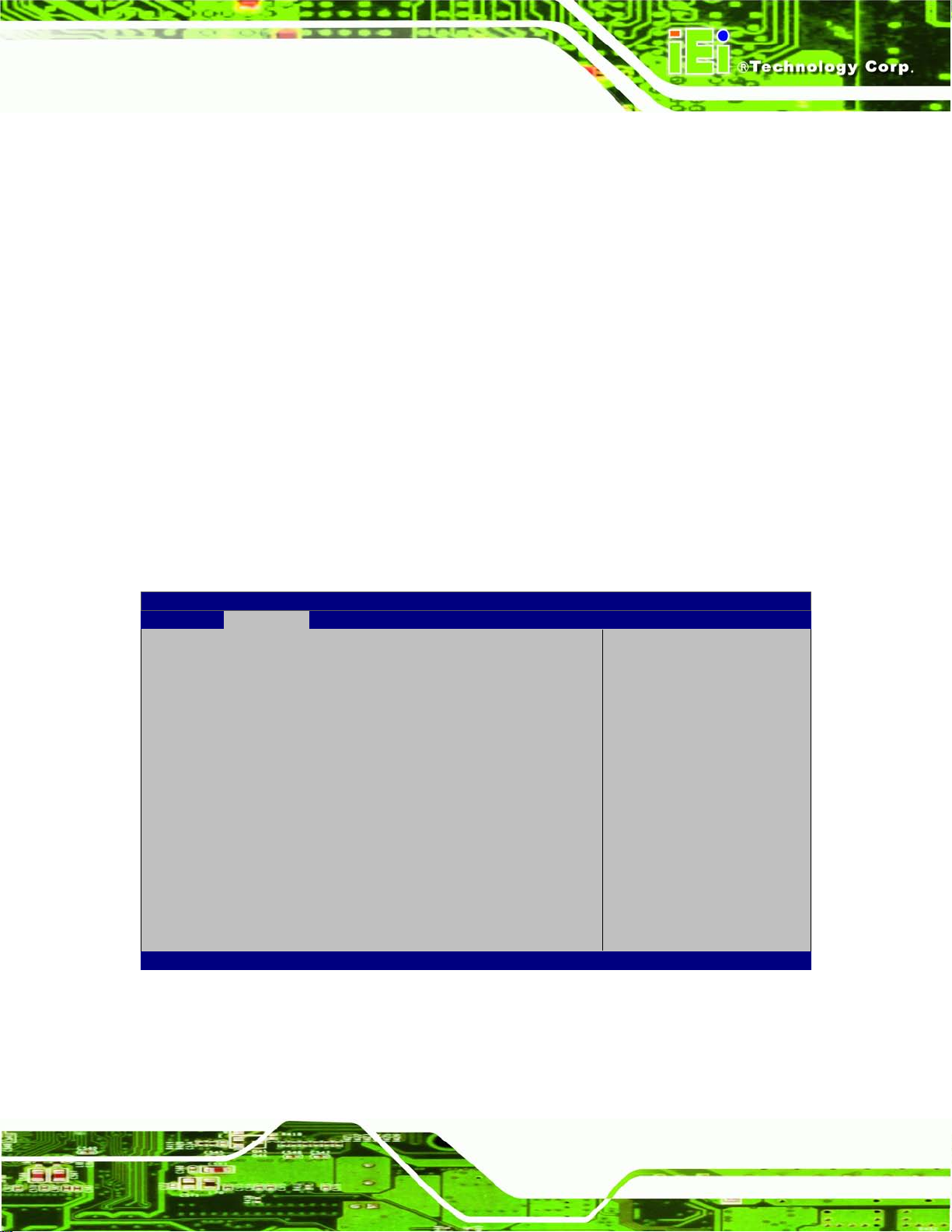
AFL2-W07A-N26
Page 73
CPU Stop
3 (Suspend to
off. Power to the RAM is maintained. The
Aptio Setup Utility – Copyright (C) 2011 American Megatrends, Inc.
Advanced
ESC Exit
Version 2.14.1219. Copyright (C) 2011 American Megatrends, Inc.
ACPI Sleep State [S1 (CPU Stop Clock)]
Use the ACPI Sleep State option to specif y the sleep stat e the system enters when it is
not being used.
S1 (
Clock)
S
RAM)
DEFAULT
The system enters S1 (POS) sleep state. The
system appears off. The CPU is stopped; RAM is
refreshed; the system is running in a low power
mode.
The caches are flushed and the C PU is pow ered
computer returns slower to a working state, but
more power is saved.
7.3.2 RTC Wake Settings
The RTC Wake Settings menu (BIOS Menu 4) configures RTC wake event.
Wake system with Fixed Time [Disabled]
Enable or disable System
wake on alarm event. When
enabled, System will
wake on the
date::hr::min::sec
specified
----------------------
: Select Screen
↑ ↓: Select Item
Enter Select
F1 General Help
F2 Previous Values
F3 Optimized Defaults
F4 Save
BIOS Menu 4: RTC Wake Settings
Wake system with Fixed Time [Disabled]
Page 90

AFL2-W07A-N26
Page 74
every day at the specified time. Besides, the
Use the Wake system w ith Fixed Time option to enable or dis able the s ystem wake on
alarm event.
Disabled D
Enabled
EFAULT
The real time clock (RTC) cannot generate a wak e
event
If selected, the Wake up every da y option appears
allowing you to enable to disable the system to wake
following options appear with values that can be
selected:
Wake up date
Wake up hour
Wake up minute
Wake up second
After setting the alarm, the computer turns itself on
from a suspend state when the alarm goes off.
Page 91
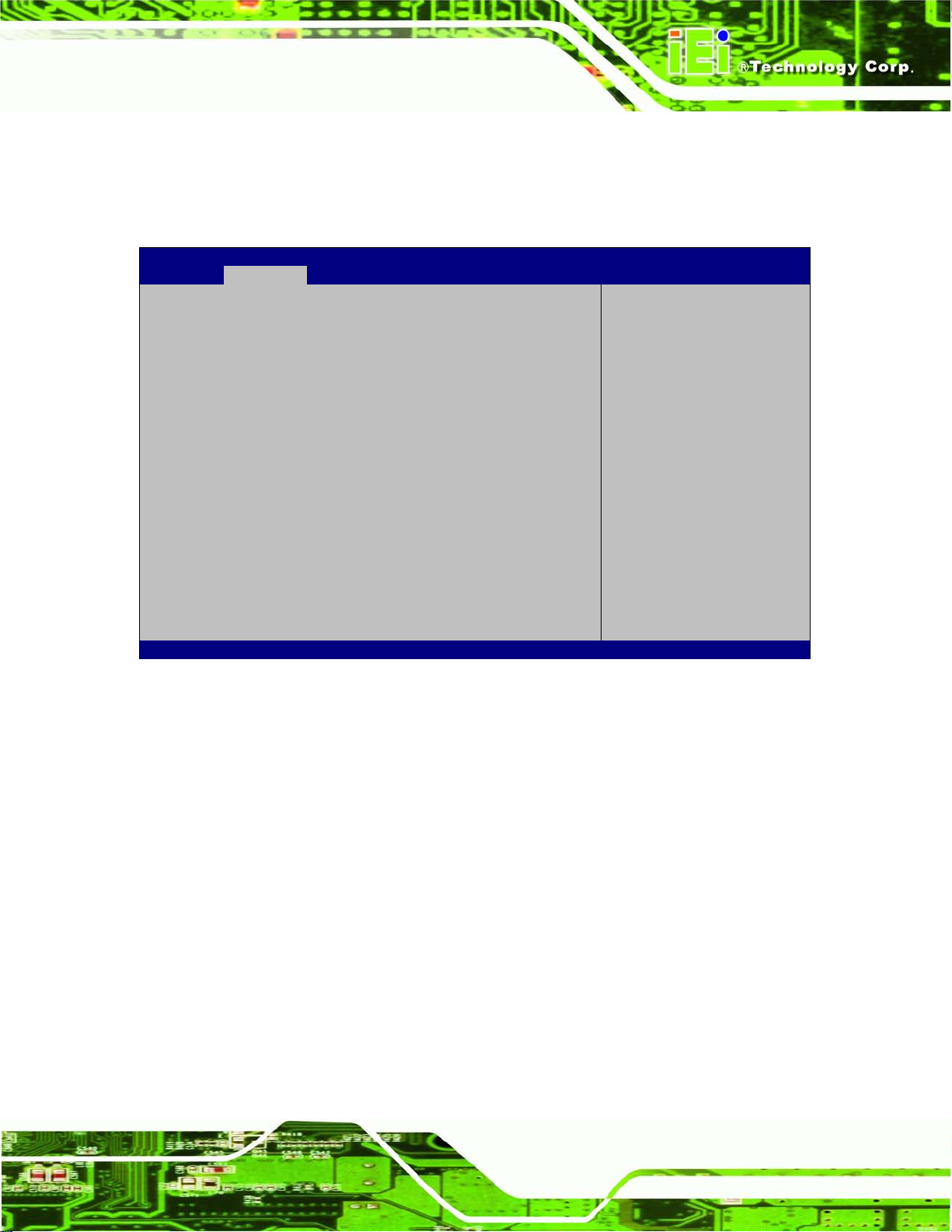
AFL2-W07A-N26
Page 75
Aptio Setup Utility – Copyright (C) 2011 American Megatrends, Inc.
Advanced
ESC Exit
Version 2.14.1219. Copyright (C) 2011 American Megatrends, Inc.
7.3.3 CPU Configuration
Use the CPU Configuration menu ( BIOS Menu 5) to view detailed CPU specifications
and configure the CPU.
CPU Configuration
Processor Type Intel(R) Atom(TM) CPU
N2600 @ 1.60GHz
EMT64 Supported
Processor Speed 1600 MHz
System Bus Speed 400 MHz
Ratio Status 16
Actual Ratio 16
Processor Stepping 30661
Processor Revision 268
L1 Cache RAM 2x56 k
L2 Cache RAM 2x512 k
Processor Core Dual
Hyper-threading Supported
Hyper-threading [Enabled]
BIOS Menu 5: CPU Configuration
The CPU Configuration menu (BIOS Menu 5) lists the following CPU details:
Enabled for Windows XP
and Linux (OS optimized
for Hyper-Threading
Technology)and Disabled
for other OS (OS not
optimized for
Hyper-Threading
Technology).
----------------------
: Select Screen
↑ ↓: Select Item
Enter Select
F1 General Help
F2 Previous Values
F3 Optimized
Defaults
F4 Save
Processor Type: Lists the brand name of the CPU being used
EMT64: Indicates if the EMT64 is supported by the CPU.
Processor Speed: Lists the CPU processing speed
System Bus Speed: Lists the system bus speed
Ratio Status: Lists the ratio status
Actual Ratio: Lists the actual ratio
Processor Stepping: Lists the CPU processing stepping
Microcode Revision: Lists the microcode revision
Cache L1 RAM: Lists the CPU L1 cache size
Cache L2 RAM: Lists the CPU L2 cache size
Processor Core: Lists the number of the processor core
Hyper-threading: Indicates if the Hyper-threading is supported by the CPU.
Page 92

AFL2-W07A-N26
Page 76
Aptio Setup Utility – Copyright (C) 2011 American Megatrends, Inc.
Advanced
Version 2.14.1219. Copyright (C) 2011 American Megatrends, Inc.
Hyper-Threading [Enabled]
Use the Hyper-Threading option to enable or disable the CPU hyper threading function.
Disabled
Enabled DEFAULT
Disables the use of hyper threading
technology
Enables the use of hyper threading
technology
7.3.4 S ATA Configuration
Use the SATA Configuration menu (BIOS Menu 6) to change and/or set the
configuration of the SATA devices installed in the system.
SATA Port0 Not Present
SATA Port1 Not Present
Configure SATA as [IDE]
Select a configuration
for SATA Controller.
---------------------
: Select Screen
↑ ↓: Select Item
Enter Select
+/-: Change Opt.
F1 General Help
F2 Previous Values
F3 Optimized Defaults
F4 Save & Exit
ESC Exit
BIOS Menu 6: IDE Configuration
Configure S ATA as [IDE]
Use the Configure SATA as option to configure SATA devices as AHCI devices.
IDE DEFAULT
AHCI
Configures SATA devices as normal IDE device.
Configures SATA devices as AHCI device.
Page 93

AFL2-W07A-N26
Page 77
Aptio Setup Utility – Copyright (C) 2011 American Megatrends, Inc.
Advanced
ESC: Exit
Version 2.14.1219. Copyright (C) 2011 American Megatrends, Inc.
7.3.5 USB Configuration
Use the USB Configuration menu (BIOS Menu 7) to read USB configurati on inf or mation
and configure the USB settings.
USB Configuration
USB Devices:
1 Drive, 1 Keyboard
Legacy USB Support [Enabled]
BIOS Menu 7: USB Configuration
USB Devices
Enables Legacy USB
support. AUTO option
disables legacy support
if no USB devices are
connected. DISABLE
option will keep USB
devices available only
for EFI application.
---------------------
: Select Screen
↑ ↓: Select Item
Enter Select
+/-: Change Opt.
F1: General Help
F2: Previous Values
F3: Optimized Defaults
F4: Save & Exit
The USB Devices Enabled field lists the USB devices that are enabled on the system
Legacy USB Support [Enabled]
Use the Legacy USB Support BIO S option to enable USB mouse and USB k eyboard
support. Normally if this option is not enabled, any attached USB mouse or USB keyboard
does not become available until a USB compatible operating system is fully booted with all
USB drivers loaded. When this option is enabled, any attached USB mouse or USB
keyboard can control the system even when there is no USB driver loaded onto the
system.
Enabled DEFAULT
Legacy USB support enabled
Page 94
AFL2-W07A-N26
Page 78
Aptio Setup Utility – Copyright (C) 2011 American Megatrends, Inc.
Advanced
ESC: Exit
Version 2.14.1219. Copyright (C) 2011 American Megatrends, Inc.
Disabled
Auto
Legacy USB support disabled
Legacy USB support disa bled if no USB de vices are
connected
7.3.6 F81866 Su pe r IO Configuration
Use the F81866 Super IO Configuration menu (BIOS Menu 8) to set or change the
configurations for the serial ports.
F81866 Super IO Configuration
F81866 Super IO Chip F81866
> Serial Port 1 Configuration
> Serial Port 2 Configuration
Set Parameters of Serial
Port 1 (COMA)
---------------------
: Select Screen
↑ ↓: Select Item
Enter Select
+/-: Change Opt.
F1: General Help
F2: Previous Values
F3: Optimized Defaults
F4: Save & Exit
BIOS Menu 8: Super IO Configuration
Page 95
AFL2-W07A-N26
Page 79
Aptio Setup Utility – Copyright (C) 2011 American Megatrends, Inc.
Advanced
ESC: Exit
Version 2.14.1219. Copyright (C) 2011 American Megatrends, Inc.
7.3.6.1 Serial Port n Configuration
Use the Serial Port n Configuration menu (BIOS Menu 9) to configure the serial port n.
Serial Port 0 Configuration
Serial Port [Enabled]
Device Settings IO=3F8h; IRQ=4
Change Settings [Auto]
BIOS Menu 9: Serial Port n Configuration Menu
7.3.6.1.1 Serial Port 1 Configuration
Serial Port [Enabled]
Use the Serial Port option to enable or disable the serial port.
Enable or Disable Serial
Port (COM)
---------------------
: Select Screen
↑ ↓: Select Item
Enter Select
+/-: Change Opt.
F1: General Help
F2: Previous Values
F3: Optimized Defaults
F4: Save & Exit
Disabled
Enabled DEFAULT
Change Settings [Auto]
Use the Change Settings option to c hange the serial port IO port address and interrupt
address.
Auto DEFAULT
IO=3F8h; IRQ=4
Disable the serial port
Enable the serial port
The serial port IO port address and interrupt
address are automatically detected.
Serial Port I/O port address is 3F8h and the
interrupt address is IRQ4
Page 96

AFL2-W07A-N26
Page 80
IO=2F8h; IRQ=3
7.3.6.1.2 Serial Port 2 Configuration
Serial Port [Enabled]
Use the Serial Port option to enable or disable the serial port.
Disabled
Enabled DEFAULT
Change Settings [Auto]
Use the Change Settings option to c hange the serial port IO port address and interrupt
address.
Auto DEFAULT
Serial Port I/O port address is 2F8h and the
interrupt address is IRQ3
Disable the serial port
Enable the serial port
The serial port IO port address and interrupt
address are automatically detected.
IO=2F8h; IRQ=3
IO=3F8h; IRQ=4
Device Mode [RS422/485]
The Device Mode shows Serial Port 2 provides RS-422/485 communications.
Serial Port I/O port address is 2F8h and the
interrupt address is IRQ3
Serial Port I/O port address is 3F8h and the
interrupt address is IRQ4
Page 97

AFL2-W07A-N26
Page 81
Aptio Setup Utility – Copyright (C) 2011 American Megatrends, Inc.
Advanced
ESC: Exit
Version 2.14.1219. Copyright (C) 2011 American Megatrends, Inc.
7.3.7 H/W Monitor
The H/W Monitor menu (BIOS Menu 10) shows the hardware health status.
CPU temperature :+56 C
System temperature :+55 C
Environment temperature :+25 C
BIOS Menu 10: Hardware Health Configuration
PC Health Status
The following system param eters and va lues ar e show n. The s ystem par am eters that are
---------------------
: Select Screen
↑ ↓: Select Item
Enter Select
+/-: Change Opt.
F1: General Help
F2: Previous Values
F3: Optimized Defaults
F4: Save & Exit
monitored are:
System Te mperatures:
o CPU Temperature
o System Temperature
o Environment Temperature
7.3.8 Se rial Port Console Redirection
The Serial Port Console Redirection menu (BIOS Menu 11) allows the console
redirection options to be configured. Console redirection allows users to maintain a
system remotely by re-directing keyboard input and text output through the serial port.
Page 98

AFL2-W07A-N26
Page 82
Aptio Setup Utility – Copyright (C) 2011 American Megatrends, Inc.
Advanced
ESC: Exit
Version 2.14.1219. Copyright (C) 2011 American Megatrends, Inc.
COM1
Console Redirection [Disabled]
> Console Redirection Settings
BIOS Menu 11: Serial Po r t Console Redirection
Console Redirection [Disabled]
Use Console Redirection option to enable or disable the console redirection function.
Disabled DEFAULT
Disabled the console redirection function
Console Redirection
Enable or Disable.
---------------------
: Select Screen
↑ ↓: Select Item
Enter Select
+/-: Change Opt.
F1: General Help
F2: Previous Values
F3: Optimized Defaults
F4: Save & Exit
Enabled
Terminal Typ e [ANSI]
Use the Terminal Type option to specify the remote terminal type.
VT100
VT100+
VT-UTF8
ANSI DEFAULT
Bits per second [115200]
Use the Bits per second option to specif y the s erial port tr ansm iss ion speed. The speed
must match the other side. Long or noisy lines may require lower speeds.
Enabled the console redirection function
The target terminal type is VT100
The target terminal type is VT100+
The target terminal type is VT-UTF8
The target terminal type is ANSI
Page 99

AFL2-W07A-N26
Page 83
9600
19200
38400
57600
115200 DEFAULT
Data B its [8]
Use the Data Bits option to specify the number of data bits.
7
8 DEFAULT
Parity [None]
Use the Parity option to specify the parity bit that can be sent with the data bits for
Sets the serial port transmission speed at 9600.
Sets the serial port transmission speed at 19200.
Sets the serial port transmission speed at 38400.
Sets the serial port transmission speed at 57600.
Sets the serial port transmission speed at 115200.
Sets the data bits at 7.
Sets the data bits at 8.
detecting the transmission errors.
None DEFAULT
Even
Odd
Mark
Space
Stop Bits [1]
Use the Stop Bits o ption to specif y the num ber of stop bits us ed to indicate t he end of a
serial data packet. Communication with slow devices may require more than 1 stop bit.
No parity bit is sent with the data bits.
The parity bit is 0 if the nu mber of ones in the data
bits is even.
The parity bit is 0 if the nu mber of ones in the data
bits is odd.
The parity bit is always 1. This option does not
provide error detection.
The parity bit is always 0. This option does not
provide error detection.
Page 100
AFL2-W07A-N26
Page 84
Aptio Setup Utility – Copyright (C) 2011 American Megatrends, Inc.
Advanced
ESC: Exit
Version 2.14.1219. Copyright (C) 2011 American Megatrends, Inc.
1 DEFAULT
2
Sets the number of stop bits at 1.
Sets the number of stop bits at 2.
7.4 iEi Fea ture
Use the iEi Feature menu (BIOS Menu 12) to configure the auto recovery function.
iEi Feature
Auto Recovery Function [Disabled]
Micro SD Card [Enabled]
Auto Recovery Function
Reboot and recover
system automatically
within 10 min, when OS
crashes. Please install
Auto Recovery API
service before enabling
this function
---------------------
: Select Screen
↑ ↓: Select Item
Enter Select
+/-: Change Opt.
F1: General Help
F2: Previous Values
F3: Optimized Defaults
F4: Save & Exit
BIOS Menu 12: iEi Feature
Auto Recovery Function [Disabled]
Use the Auto Recovery Function option to enable or disable auto recovery on the
system.
Disabled DEFAULT
Enabled
Auto Recovery Function support disabled
Auto Recovery Function support enabled
 Loading...