

Page 1
Page I
IEI Technology Corp.
User Manual
AFL2-10A-N28 Panel PC
MODEL:
AFL2-10A-N28 Series
Flat Bezel Panel PC with Intel® Atom™ N2800 Dual-Core CPU
Touchscreen, Wi-Fi, Bluetooth, USB, GbE LAN, RS-232/422/485,
2-Megapixel Camera, HD Audio and RoHS
User Manual
Rev. 1.00 - 26 February, 2013
Page 2
Date Version Changes
AFL2-10A-N28 Panel PC
Revision
26 February, 2013 1.00
Initial release
Page II
Page 3

Page III
Copyright
COPYRIGHT NOTICE
The information in this document is subject to change without prior notice in order to
improve reliability, design and function and does not represent a commitment on the part
of the manufacturer.
In no event will the manufacturer be liable for direct, indirect, special, incidental, or
consequential damages arising out of the use or inability to use the product or
documentation, even if advised of the possibility of such damages.
This document contains proprietary information protected by copyright. All rights are
reserved. No part of this manual may be reproduced by any mechanical, electronic, or
other means in any form without prior written permission of the manufacturer.
TRADEMARKS
All registered trademarks and product names mentioned herein are used for identification
purposes only and may be trademarks and/or registered trademarks of their respective
owners.
AFL2-10A-N28 Panel PC
Page 4

AFL2-10A-N28 Panel PC
Table of Contents
1 INTRODUCTION.......................................................................................................... 1
1.1 OVERVIEW.................................................................................................................. 2
1.1.1 Features ............................................................................................................. 3
1.2 EXTERNAL OVERVIEW................................................................................................ 3
1.2.1 Front Panel........................................................................................................ 3
1.2.1.1 LED Indicators............................................................................................ 4
1.2.1.2 Function Keys............................................................................................. 6
1.2.2 Rear Panel ......................................................................................................... 7
1.2.3 Bottom Panel...................................................................................................... 7
1.2.4 Left Side Panel................................................................................................... 8
1.3 INTERNAL OVERVIEW................................................................................................. 9
1.4 SYSTEM SPECIFICATIONS............................................................................................ 9
1.5 DIMENSIONS..............................................................................................................11
2 UNPACKING............................................................................................................... 12
2.1 UNPACKING.............................................................................................................. 13
2.1.1 Packing List ..................................................................................................... 13
3 INSTALLATION ......................................................................................................... 17
3.1 ANTI-STATIC PRECAUTIONS...................................................................................... 18
3.2 INSTALLATION PRECAUTIONS ................................................................................... 18
3.3 INST ALLATION AND CONFIGURATION STEPS............................................................. 19
3.4 HDD INSTALLATION................................................................................................. 19
3.5 RFID READER INSTALLATION (OPTIONAL) .............................................................. 22
3.6 AT/ATX MODE SELECTION...................................................................................... 24
3.6.1 AT Power Mode................................................................................................ 24
3.6.2 ATX Power Mode............................................................................................. 24
3.7 CLEAR CMOS.......................................................................................................... 25
3.8 RESET THE SYSTEM.................................................................................................. 25
3.9 POWERING ON THE SYSTEM..................................................................................... 26
3.10 POWERING OFF THE SYSTEM.................................................................................. 26
Page IV
Page 5

Page V
3.11 MOUNTING THE SYSTEM ........................................................................................ 26
3.1 1.1 Wall Mounting................................................................................................ 27
3.11.2 Panel Mounting.............................................................................................. 30
3.11.3 Cabinet and Rack Installation........................................................................ 31
3.1 1.4 Arm Mounting ................................................................................................ 34
3.11.5 Stand Mounting.............................................................................................. 36
3.1 1.6 V-Stand Mounting........................................................................................... 36
3.12 EXTERNAL PERIPHERAL DEVICE CONNECTION ...................................................... 38
3.12.1 Audio Connection........................................................................................... 39
3.12.2 DisplayPort Connection................................................................................. 39
3.12.3 LAN Connection............................................................................................. 40
3.12.4 Serial Device Connection .............................................................................. 41
3.12.4.1 DB-9 Serial Port Connection.................................................................. 41
3.12.4.2 RJ-45 Serial Port Connection.................................................................. 42
3.12.5 USB Device Connection................................................................................. 44
4 BIOS SETUP................................................................................................................ 45
4.1 INTRODUCTION......................................................................................................... 46
4.1.1 Starting Setup................................................................................................... 46
4.1.2 Using Setup...................................................................................................... 46
4.1.3 Getting Help..................................................................................................... 47
4.1.4 Unable to Reboot after Configuration Changes.............................................. 47
4.1.5 BIOS Menu Bar................................................................................................ 47
4.2 MAIN........................................................................................................................ 48
4.3 ADVANCED............................................................................................................... 49
4.3.1 ACPI Settings................................................................................................... 50
4.3.2 RTC Wake Settings ........................................................................................... 51
4.3.3 CPU Configuration.......................................................................................... 52
4.3.4 SATA Configuration ......................................................................................... 54
4.3.5 USB Configuration........................................................................................... 55
4.3.6 F81866 Super IO Configuration...................................................................... 56
4.3.6.1 Serial Port n Configuration....................................................................... 57
4.3.6.1.1 Serial Port 1 Configuration................................................................ 57
4.3.6.1.2 Serial Port 2 Configuration................................................................ 58
4.3.6.1.3 Serial Port 3 Configuration................................................................ 58
AFL2-10A-N28 Panel PC
Page 6

4.3.7 H/W Monitor.................................................................................................... 60
4.3.8 Serial Port Console Redirection...................................................................... 60
4.4 IEI FEATURE ............................................................................................................. 62
4.5 CHIPSET ................................................................................................................... 63
4.5.1 Host Bridge Configuration .............................................................................. 64
4.5.1.1 Internal IGD Configuration....................................................................... 64
4.5.2 South Bridge Configuration............................................................................. 65
4.6 BOOT........................................................................................................................ 67
4.7 SECURITY................................................................................................................. 69
4.8 SAVE & EXIT ............................................................................................................ 70
5 SOFTWARE DRIVERS.............................................................................................. 72
5.1 AVAILABLE SOFTWARE DRIVERS.............................................................................. 73
5.2 ST ARTING THE DRIVER PROGRAM ............................................................................ 73
5.3 CHIPSET DRIVER INSTALLATION............................................................................... 74
AFL2-10A-N28 Panel PC
5.4 GRAPHICS DRIVER INSTALLATION............................................................................ 77
5.5 TOUCH SCREEN DRIVER........................................................................................... 80
5.5.1 Calibrating the Touch Screen........................................................................... 83
5.6 AUDIO DRIVER INSTA LLATION ................................................................................. 86
5.7 LAN DRIVER INSTALLATION.................................................................................... 88
5.8 USB 3.0 DRIVER INSTALLATION .............................................................................. 90
5.9 WI-FI DRIVER INSTALLATION................................................................................... 93
5.10 BLUETOOTH DRIVER.............................................................................................. 96
5.11 CAMERA DRIVER INSTALLATION .......................................................................... 100
6 SYSTEM MAINTENANCE ..................................................................................... 103
6.1 SYSTEM MAINTENANCE INTRODUCTION ................................................................ 104
6.2 ANTI-STATIC PRECAUTIONS.................................................................................... 104
6.3 TURN OFF THE POWER............................................................................................ 105
6.4 OPENING THE SYSTEM............................................................................................ 105
6.4.1 Removing the Back Cover.............................................................................. 105
6.4.2 Removing the Internal Cover......................................................................... 106
6.5 REPLACING COMPONENTS...................................................................................... 108
6.5.1 Memory Module Replacement ....................................................................... 108
6.5.2 WLAN Card Replacement.............................................................................. 109
Page VI
Page 7

Page VII
6.6 REINST ALLING THE COVERS....................................................................................112
7 INTERFACE CONNECTORS..................................................................................113
7.1 PERIPHERAL INTERFACE CONNECTORS....................................................................114
7.2 INTERNAL PERIPHERAL CONNECTORS .....................................................................115
7.2.1 Audio Connector (AUDIO1)...........................................................................117
7.2.2 Battery Connector (CN2)................................................................................117
7.2.3 Bluetooth USB Connector (BLUETOOTH1)..................................................117
7.2.4 CRT Connector (VGA1)..................................................................................118
7.2.5 Debug Connector (LPC_DEBUG1) ...............................................................118
7.2.6 EC Debug Connector (CN1)...........................................................................118
7.2.7 HDD Connector (JSATA1)..............................................................................119
7.2.8 Hot Key LED Connector (HOTKEYLEDCN1)...............................................119
7.2.9 Hot Key Connector (HOTKEYCN1).............................................................. 120
7.2.10 LED Indicator Connector (LEDCN1).......................................................... 120
7.2.11 LVDS Connector (LCD1)............................................................................. 120
7.2.12 LVDS Backlight Connector (INVERTER1).................................................. 121
7.2.13 microSD Connector (MICRO_SD1)............................................................ 121
7.2.14 Mini USB Connector (MINI_USB1)............................................................ 121
7.2.15 Power Button Connector (PW_BT1) ........................................................... 122
7.2.16 RFID USB Connector (RFID1) ................................................................... 122
7.2.17 RFID COM Connector (RFID_COM1)....................................................... 122
7.2.18 SATA LED Connector (JP5)......................................................................... 122
7.2.19 Speaker Connector (SPKR1)........................................................................ 123
7.2.20 SPI Flash Connector (SPI1) ........................................................................ 123
7.2.21 EC SPI Flash Connector (JSPI2) ................................................................ 123
7.2.22 Touch Panel Connector (TS1)...................................................................... 124
7.2.23 Touch Panel Connector (TOUCH1)............................................................. 124
7.2.24 Type K Thermocouple Connector (K_TYPE1, K_TYPE2)........................... 124
7.2.25 Webcam Connector (CAMERA1)................................................................. 125
7.2.26 Webcam Microphone Connector (WEBCAM_DMIC1) ............................... 125
7.3 EXTERNAL INTERFACE PANEL CONNECTORS .......................................................... 125
7.3.1 Ethernet Connector (JP6).............................................................................. 126
7.3.2 Power Connector (DC_IN1)....................................................................... 126
7.3.3 RS-232 DB-9 Serial Ports (COM1) ............................................................... 126
AFL2-10A-N28 Panel PC
Page 8

7.3.4 RS-422/485 RJ-45 Serial Port (COM2)......................................................... 127
7.3.5 RS-232 RJ-45 Serial Ports (COM3) .............................................................. 127
7.3.6 USB 2.0 Connectors (USB1).......................................................................... 128
7.3.7 USB 3.0 Connectors (USB3_1)...................................................................... 128
7.3.8 DisplayPort Connector (DISPLAY_PORT1) ................................................. 128
A SAFETY PRECAUTIONS....................................................................................... 130
A.1 SAFETY PRECAUTIONS .......................................................................................... 131
A.1.1 General Safety Precautions........................................................................... 131
A.1.2 CPU Temperature Warning ........................................................................... 132
A.1.3 Anti-static Precautions.................................................................................. 132
A.1.4 Product Disposal........................................................................................... 133
A.2 MAINTENANCE AND CLEANING PRECAUTIONS...................................................... 133
A.2.1 Maintenance and Cleaning............................................................................ 133
A.2.2 Cleaning Tools............................................................................................... 134
AFL2-10A-N28 Panel PC
B BIOS MENU OPTIONS........................................................................................... 135
C ONE KEY RECOVERY........................................................................................... 138
C.1 ONE KEY RECOVERY INTRODUCTION .................................................................... 139
C.1.1 System Requirement ...................................................................................... 140
C.1.2 Supported Operating System......................................................................... 141
C.2 SETUP PROCEDURE FOR WINDOWS........................................................................ 142
C.2.1 Hardware and BIOS Setup ............................................................................ 143
C.2.2 Create Partitions........................................................................................... 143
C.2.3 Install Operating System, Drivers and Applications..................................... 147
C.2.4 Building the Recovery Partition.................................................................... 148
C.2.5 Create Factory Default Image ...................................................................... 150
C.3 AUTO RECOVERY SETUP PROCEDURE.................................................................... 155
C.4 SETUP PROCEDURE FOR LINUX.............................................................................. 160
C.5 RECOVERY TOOL FUNCTIONS ................................................................................ 163
C.5.1 Factory Restore............................................................................................. 165
C.5.2 Backup System............................................................................................... 166
C.5.3 Restore Your Last Backup.............................................................................. 167
C.5.4 Manual .......................................................................................................... 168
C.6 RESTORE SYSTEMS FROM A LINUX SERVER THROUGH LAN.................................. 169
Page VIII
Page 9

Page IX
C.6.1 Configure DHCP Server Settings.................................................................. 170
C.6.2 Configure TFTP Settings............................................................................... 171
C.6.3 Configure One Key Recovery Server Settings............................................... 172
C.6.4 Start the DHCP, TFTP and HTTP................................................................. 173
C.6.5 Create Shared Directory................................................................................ 173
C.6.6 Setup a Client System for Auto Recovery...................................................... 174
C.7 OTHER INFORMATIO N ............................................................................................ 177
C.7.1 Using AHCI Mode or ALi M5283 / VIA VT6421A Controller ...................... 177
C.7.2 System Memory Requirement........................................................................ 179
D WATCHDOG TIMER .............................................................................................. 180
E HAZARDOUS MATERIALS DISCLOSURE ....................................................... 183
E.1 HAZARDOUS MATERIAL DISCLOSURE TABLE FOR IPB PRODUCTS CERTIFIED AS
ROHS COMPLIANT UNDER 2002/95/EC WITHOUT MERCURY ..................................... 184
AFL2-10A-N28 Panel PC
Page 10

AFL2-10A-N28 Panel PC
List of Figures
Figure 1-1: AFL2-10A-N28 Flat Bezel Panel PC...........................................................................2
Figure 1-2: Front View....................................................................................................................3
Figure 1-3: LED Indicators.............................................................................................................4
Figure 1-4: Function Keys .............................................................................................................6
Figure 1-5: Rear View.....................................................................................................................7
Figure 1-6: Bottom Panel...............................................................................................................8
Figure 1-7: Left Side Panel ............................................................................................................8
Figure 1-8: AFL2-10A-N28 Dimensions (mm) ............................................................................11
Figure 3-1: HDD Cover Retention Screws..................................................................................20
Figure 3-2: HDD Bracket Removal..............................................................................................20
Figure 3-3: Inserting the HDD......................................................................................................21
Figure 3-4: Securing the HDD......................................................................................................21
Figure 3-5: Back Cover Retention Screws.................................................................................22
Figure 3-6: Internal Cover Retention Screws.............................................................................22
Figure 3-7: RFID Reader Module Installation.............................................................................23
Figure 3-8: RFID Reader Connection..........................................................................................23
Figure 3-9: AT/ATX Switch Location...........................................................................................24
Figure 3-10: Clear CMOS Switch Location.................................................................................25
Figure 3-11: Reset Button Location............................................................................................25
Figure 3-12: Wall-mounting Bracket...........................................................................................27
Figure 3-13: Chassis Support Screws........................................................................................29
Figure 3-14: Secure the Panel PC...............................................................................................29
Figure 3-15: Cutout Dimensions.................................................................................................30
Figure 3-16: Tighten the Panel Mounting Clamp Screws.........................................................31
Figure 3-17: The Rack/Cabinet Bracket......................................................................................32
Figure 3-18: Secure the Rack/Cabinet Bracket..........................................................................33
Figure 3-19: Install into a Rack/Cabinet .....................................................................................33
Figure 3-20: Arm Mounting Retention Screw Holes..................................................................35
Figure 3-21: Arm Mounting..........................................................................................................35
Figure 3-22: Stand Mounting (Stand-A/Bxx)..............................................................................36
Figure 3-23: Drill Pilot Holes for V-Stand...................................................................................37
Page X
Page 11

Page XI
Figure 3-24: Secure System to V-Stand .....................................................................................37
Figure 3-25: Secure V-Stand to Mounting Area.........................................................................38
Figure 3-26: Audio Connector.....................................................................................................39
Figure 3-27: DisplayPort Connection.........................................................................................40
Figure 3-28: LAN Connection......................................................................................................41
Figure 3-29: DB-9 Serial Port Connector....................................................................................42
Figure 3-30: RJ-45 Serial Port Connector..................................................................................43
Figure 3-31: DB-9 Connector Pinout Locations ........................................................................43
Figure 3-32: USB Device Connection.........................................................................................44
Figure 5-1: Drivers........................................................................................................................74
Figure 5-2: Chipset Driver Screen...............................................................................................75
Figure 5-3: Chipset Driver Welcome Screen..............................................................................75
Figure 5-4: Chipset Driver License Agreement.........................................................................76
Figure 5-5: Chipset Driver Read Me File ....................................................................................76
Figure 5-6: Chipset Driver Setup Operations ............................................................................77
Figure 5-7: Graphics Driver Welcome Screen...........................................................................78
Figure 5-8: Graphics Driver License Agreement.......................................................................78
Figure 5-9: Graphics Driver Read Me File..................................................................................79
Figure 5-10: Graphics Driver Setup Operations........................................................................79
Figure 5-11: Graphics Driver Installation Finish Screen ..........................................................80
Figure 5-12: Touch Screen Driver Welcome Screen.................................................................81
Figure 5-13: Touch Screen Driver License Agreement.............................................................81
Figure 5-14: Touch Screen Driver Choose Install Location.....................................................82
Figure 5-15: Touch Screen Driver Installation Screen..............................................................82
Figure 5-16: Touch Screen Driver Update Complete................................................................83
Figure 5-17: PenMount Monitor Icon..........................................................................................83
Figure 5-18: PenMount Monitor Popup Menu............................................................................84
Figure 5-19: Configuration Screen..............................................................................................84
Figure 5-20: Calibration Initiation Screen..................................................................................85
Figure 5-21: Calibration Screen ..................................................................................................85
Figure 5-22: Audio Driver – Extracting Files..............................................................................86
Figure 5-23: Audio Driver Welcome Screen...............................................................................87
Figure 5-24: Audio Driver Installation.........................................................................................87
Figure 5-25: Audio Driver Installation Complete.......................................................................87
Figure 5-26: LAN Driver Welcome Screen .................................................................................88
AFL2-10A-N28 Panel PC
Page 12

Figure 5-27: LAN Driver Ready to Install Screen.......................................................................89
Figure 5-28: LAN Driver Setup Status Screen...........................................................................89
Figure 5-29: LAN Driver Installation Complete..........................................................................90
Figure 5-30: USB 3.0 Driver Welcome Screen...........................................................................91
Figure 5-31: USB 3.0 Driver License Agreement.......................................................................91
Figure 5-32: USB 3.0 Driver Installation.....................................................................................92
Figure 5-33: USB 3.0 Driver Update Complete ..........................................................................92
Figure 5-34: License Agreement.................................................................................................93
Figure 5-35: Setup Type...............................................................................................................94
Figure 5-36: Configuration Tool..................................................................................................94
Figure 5-37: Ready to Install the Program.................................................................................95
Figure 5-38: Setup Status ............................................................................................................95
Figure 5-39: Installation Complete..............................................................................................96
Figure 5-40: Welcome Screen .....................................................................................................97
AFL2-10A-N28 Panel PC
Figure 5-41: License Agreement.................................................................................................97
Figure 5-42: Bluetooth Driver Destination Folder.....................................................................98
Figure 5-43: Ready to Install the Program.................................................................................98
Figure 5-44: Installing BlueSoleil................................................................................................99
Figure 5-45: Bluetooth Driver Complete Installation Screen ...................................................99
Figure 5-46: Reboot the Computer .......................................................................................... 100
Figure 5-47: AMCap Driver Welcome Screen ......................................................................... 101
Figure 5-48: AMCap Driver Choose Install Location.............................................................. 101
Figure 5-49: AMCap Driver Installation Complete.................................................................. 102
Figure 6-1: Back Cover Retention Screws.............................................................................. 106
Figure 6-2: Internal Cover Retention Screws.......................................................................... 107
Figure 6-3: Internal Components............................................................................................. 107
Figure 6-4: DDR SO-DIMM Module Installation....................................................................... 109
Figure 6-5: Releasing the WLAN Card..................................................................................... 110
Figure 6-6: Removing the WLAN card..................................................................................... 110
Figure 6-7: Attaching the Antennas......................................................................................... 111
Figure 7-1: Main Board Layout Diagram (Front Side)............................................................ 114
Figure 7-2: Main Board Layout Diagram (Solder Side).......................................................... 115
Figure C-1: IEI One Key Recovery Tool Menu........................................................................ 139
Figure C-2: Launching the Recovery Tool.............................................................................. 144
Figure C-3: Recovery Tool Setup Menu .................................................................................. 144
Page XII
Page 13

Page XIII
Figure C-4: Command Prompt ................................................................................................. 145
Figure C-5: Partition Creation Commands.............................................................................. 146
Figure C-6: Launching the Recovery Tool.............................................................................. 148
Figure C-7: Manual Recovery Environment for Windows..................................................... 148
Figure C-8: Building the Recovery Partition........................................................................... 149
Figure C-9: Press Any Key to Continue.................................................................................. 149
Figure C-10: Press F3 to Boot into Recovery Mode............................................................... 150
Figure C-11: Recovery Tool Menu ........................................................................................... 150
Figure C-12: About Symantec Ghost Window........................................................................ 151
Figure C-13: Symantec Ghost Path ......................................................................................... 151
Figure C-14: Select a Local Source Drive ............................................................................... 152
Figure C-15: Select a Source Partition from Basic Drive ...................................................... 152
Figure C-16: File Name to Copy Image to ............................................................................... 153
Figure C-17: Compress Image.................................................................................................. 153
Figure C-18: Image Creation Confirmation............................................................................. 154
Figure C-19: Image Creation Complete................................................................................... 154
Figure C-20: Image Creation Complete................................................................................... 154
Figure C-21: Press Any Key to Continue................................................................................ 155
Figure C-22: Auto Recovery Utility.......................................................................................... 156
Figure C-23: Disable Automatically Restart............................................................................ 156
Figure C-24: Launching the Recovery Tool............................................................................ 157
Figure C-25: Auto Recovery Environment for Windows ....................................................... 157
Figure C-26: Building the Auto Recovery Partition................................................................ 158
Figure C-27: Factory Default Image Confirmation ................................................................. 158
Figure C-28: Image Creation Complete................................................................................... 159
Figure C-29: Press any key to continue.................................................................................. 159
Figure C-30: Partitions for Linux.............................................................................................. 161
Figure C-31: Manual Recovery Environment for Linux ......................................................... 162
Figure C-32: Access menu.lst in Linux (Text Mode).............................................................. 162
Figure C-33: Recovery Tool Menu ........................................................................................... 163
Figure C-34: Recovery Tool Main Menu.................................................................................. 164
Figure C-35: Restore Factory Default...................................................................................... 165
Figure C-36: Recovery Complete Window.............................................................................. 165
Figure C-37: Backup System.................................................................................................... 166
Figure C-38: System Backup Complete Window ................................................................... 166
AFL2-10A-N28 Panel PC
Page 14

Figure C-39: Restore Backup................................................................................................... 167
Figure C-40: Restore System Backup Complete Window..................................................... 167
Figure C-41: Symantec Ghost Window ................................................................................... 168
Figure C-42: Disable Automatically Restart............................................................................ 175
AFL2-10A-N28 Panel PC
Page XIV
Page 15

Page XV
List of Tables
Table 1-1: LED Indicators ..............................................................................................................5
Table 1-2: Function Key Descriptions..........................................................................................6
Table 1-3: System Specifications................................................................................................10
Table 3-1: DB-9 Connector Pinout..............................................................................................43
Table 6-1: BIOS Navigation Keys................................................................................................47
Table 7-1: Peripheral Interface Connectors............................................................................ 116
Table 7-2: Audio Connector (AUDIO1) Pinouts...................................................................... 117
Table 7-3: Battery Connector (CN2) Pinouts .......................................................................... 117
Table 7-4: Bluetooth USB Connector (BLUETOOTH1) Pinouts............................................ 117
Table 7-5: CRT Connector (VGA1) Pinouts............................................................................. 118
Table 7-6: Debug Connector (LPC_DEBUG1) Pinouts........................................................... 118
Table 7-7: EC Debug Connector (CN1) Pinouts...................................................................... 119
Table 7-8: HDD Connector (JSTAT1) Pinouts......................................................................... 119
Table 7-9: Hotkey LED Connector (HOTKEYLEDCN1) Pinouts............................................ 119
Table 7-10: Hotkey Connector (HOTKEYCN1) Pinouts.......................................................... 120
Table 7-11: LED Indicator Connector (LEDCN1) Pinouts...................................................... 120
Table 7-12: LVDS Connector (LCD1) Pinouts......................................................................... 121
Table 7-13: LVDS Backlight Connector (INVERTER1) Pinouts............................................. 121
Table 7-14: microSD Connector (MICRO_SD1) Pinouts........................................................ 121
Table 7-15: Mini USB Connector (MINI_USB1) Pinouts......................................................... 121
Table 7-16: Power Button Connector (PW_BT1) Pinouts...................................................... 122
Table 7-17: RFID USB Connector (RFID1) Pinouts................................................................. 122
Table 7-18: RFID COM Connector (RFID_COM1) Pinouts ..................................................... 122
Table 7-19: SATA LED Connector (JP5) Pinouts.................................................................... 122
Table 7-20: Speaker Connector (SPKR1) Pinouts.................................................................. 123
Table 7-21: SPI Flash Connector (SPI1) Pinouts.................................................................... 123
Table 7-22: EC SPI Flash Connector (JSPI2) Pinouts............................................................ 123
Table 7-23: Touch Panel Connector (TS1) Pinouts................................................................ 124
Table 7-24: Touch Panel Connector (TOUCH1) Pinouts........................................................ 124
Table 7-25: Type K Thermocouple Connector Pinouts.......................................................... 124
Table 7-26: Webcam Connector (CAMERA1) Pinouts ........................................................... 125
AFL2-10A-N28 Panel PC
Page 16

Table 7-27: Webcam Microphone Connector (WEBCAM_DMIC1) Pinouts.......................... 125
Table 7-28: Rear Panel Connectors......................................................................................... 125
Table 7-29: Ethernet Connector (JP6) Pinouts....................................................................... 126
Table 7-30: Power Connector (DC_IN1) Pinouts .................................................................... 126
Table 7-31: RS-232 DB-9 Serial Ports (COM1) Pinouts.......................................................... 126
Table 7-32: RS-422/485 Serial Port (COM2) Pinouts .............................................................. 127
Table 7-33: DB-9 Connector Pinout......................................................................................... 127
Table 7-34: RS-232 RJ-45 Serial Ports (COM3) Pinouts......................................................... 127
Table 7-35: USB 2.0 Connectors (USB1) Pinouts................................................................... 128
Table 7-36: USB 3.0 Connectors (USB3_1) Pinouts............................................................... 128
Table 7-37: DisplayPort Connector (DISPLAY_PORT1) Pinouts.......................................... 129
AFL2-10A-N28 Panel PC
Page XVI
Page 17

AFL2-10A-N28
List of BIOS Menus
BIOS Menu 1: Main.......................................................................................................................48
BIOS Menu 2: Advanced..............................................................................................................50
BIOS Menu 3: ACPI Configuration..............................................................................................50
BIOS Menu 4: RTC Wake Settings..............................................................................................51
BIOS Menu 5: CPU Configuration...............................................................................................53
BIOS Menu 6: SATA Configuration.............................................................................................54
BIOS Menu 7: USB Configuration...............................................................................................55
BIOS Menu 8: Super IO Configuration........................................................................................56
BIOS Menu 9: Serial Port n Configuration Menu.......................................................................57
BIOS Menu 10: Hardware Health Configuration........................................................................60
BIOS Menu 11: Serial Port Console Redirection.......................................................................61
BIOS Menu 12: iEi Feature...........................................................................................................62
BIOS Menu 13: Chipset................................................................................................................63
BIOS Menu 14: Northbridge Chipset Configuration..................................................................64
BIOS Menu 15: Internal IGD Configuration................................................................................64
BIOS Menu 16: South Bridge Configuration..............................................................................66
BIOS Menu 17: Boot.....................................................................................................................67
BIOS Menu 18: Security...............................................................................................................69
BIOS Menu 19: Exit.......................................................................................................................70
BIOS Menu 20: IEI Feature........................................................................................................ 160
Page XVII
Page 18
AFL2-10A-N28 Panel PC
Chapter
1
1 Introduction
Page 1
Page 19
AFL2-10A-N28 Panel PC
1.1 Overview
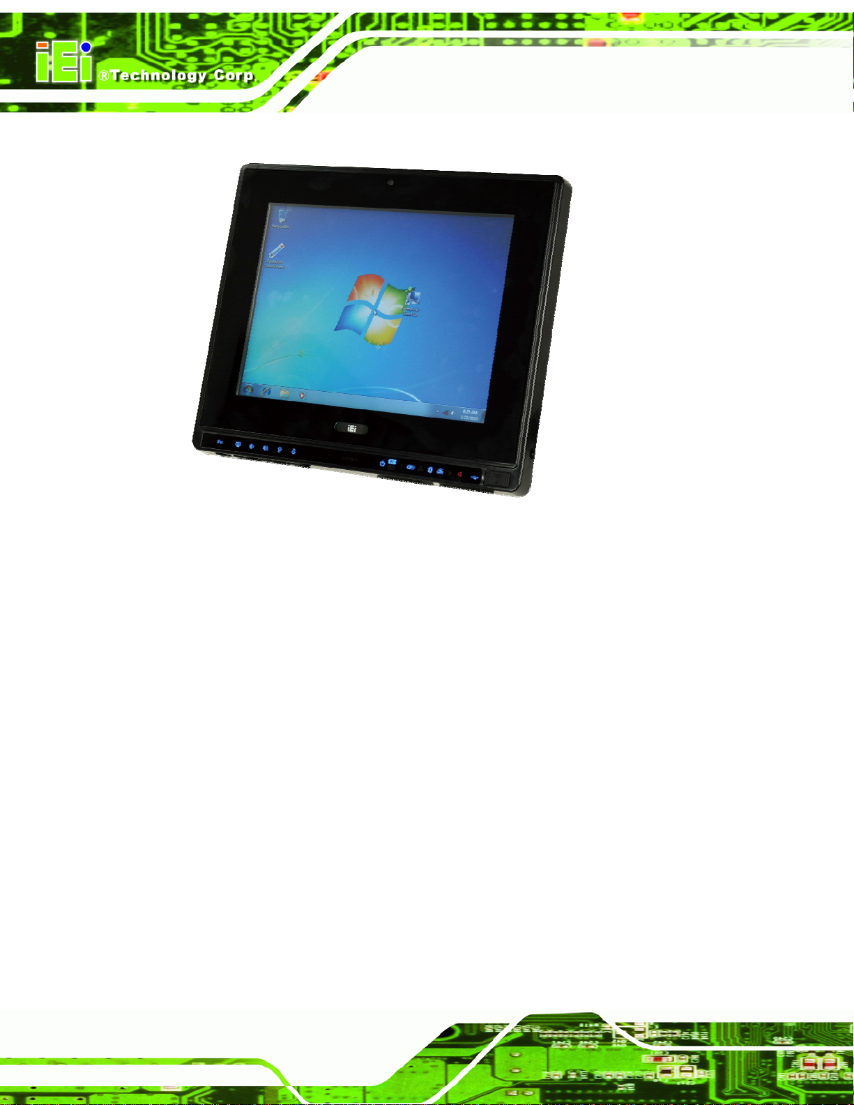
Figure 1-1: AFL2-10A-N28 Flat Bezel Panel PC
The AFL2-10A-N28 is an Intel® Atom™ N2800 dual-core processor powered flat bezel
panel PC with a rich variety of functions and peripherals. The AFL2-10A-N28 is designed
for easy and simplified integration into kiosk and point-of-sales (POS) applications.
An Intel® NM10 chipset ensures optimal memory, graphics, and peripheral I/O support.
The system comes with two 2.0 GB of DDR3 SO-DIMMs ensuring smooth data
throughputs with reduced bottlenecks and fast system access.
Three serial ports, two external USB 2.0 ports and two external USB 3.0 ports ensure
simplified connectivity to a variety of external peripheral devices. Wi-Fi capabilities and
one RJ-45 Ethernet connector provide the system with smooth connection to an external
LAN. An optional MSR card reader can equip the system for scanning credit cards,
identification cards, loyalty cards, gift cards, and more.
Page 2
Page 20
AFL2-10A-N28 Panel PC
1.1.1 Features
The AFL2-10A-N28 features are listed below:
Flat-bezel LCD with LED backlight
1.86 GHz Intel® Atom™ N2800 dual-cor e processor
One 204-pin DDR3 SO-DIMM slot (system max. 4 GB) preinstalled with 2 GB
memory
5-wire resistive type touchscreen
Wi-Fi 802.11b/g/n 2T2R high speed wireless
Built-in 2-megapixel camera with AF, AE and AWB capabilities
Built-in two 1.5 W speakers and digital microphone
Optional RFID reader
IP 64 compliant front panel
1.2 External Overview
1.2.1 Front Panel
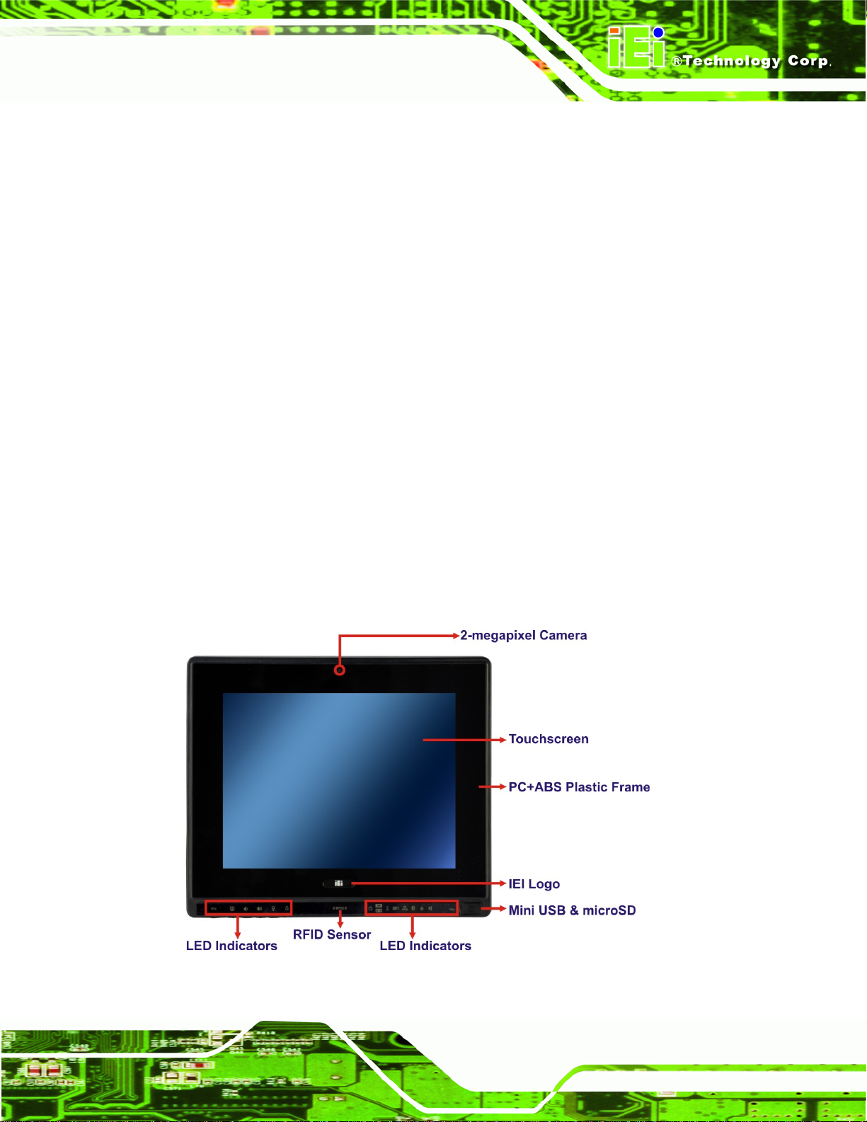
The front side of the AFL2-10A-N28 is a flat bezel panel TFT LCD screen surrou nded by a
PC/ABS plastic frame.
Figure 1-2: Front View
Page 3
Page 21
AFL2-10A-N28 Panel PC
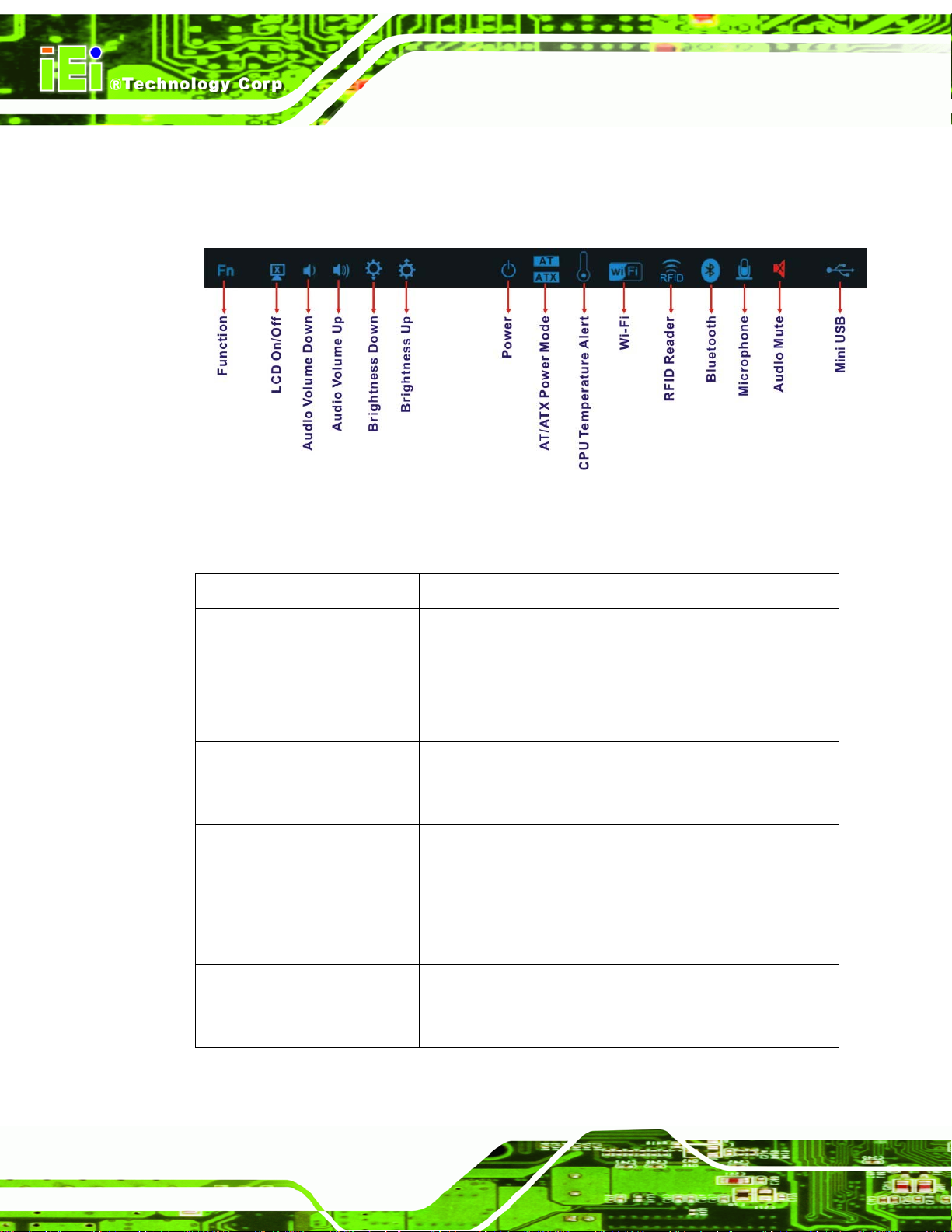
1.2.1.1 LED Indicators
There are several LED indicators located along the bottom of the LCD screen (Figure
1-3).
Figure 1-3: LED Indicators
The descriptions of each LED indicator are listed below.
LED Indicator Description
Power
AT/ATX Mode
CPU Temperature Alert
Wi-Fi
RFID
Off: power cord not attached or power supply failure
Blinking amber: the system is connected to a power
source and is ready to be turned on.
Solid blue: the system is turned on.
Power on/off by the hot keys. See
AT: the system is in AT power mode
ATX: the system is in ATX power mode
Controlled by the AT/ATX power mode switch.
Blue: CPU temperature is normal.
Red: CPU temperature is too high.
On: the Wi-Fi module is enabled
Off: the Wi-Fi module is disabled.
Controlled by the BIOS. See Section
On: the optional RFID reader is enabled
Off: the optional RFID reader is disabled.
Controlled by the hot keys. See
Table 1-3
4.5.2
Table 1-3
Page 4
Page 22
AFL2-10A-N28 Panel PC
Bluetooth
Microphone
Audio Mute
Mini USB
Function
LCD On/Off
Audio Volume Down
Audio Volume Up
On: the Bluetooth module is enabled.
Off: the Bluetooth module is disabled.
Controlled by the BIOS. See Section
On: the digital microphone is enabled
Off: the digital microphone is disabled.
Controlled by the BIOS. See Section
On (solid red): the audio is turned off
Off: the audio is turned on
Controlled by the hot keys. See
On: the Mini USB 2.0 module is enabled
Off: the Mini USB 2.0 module is disabled.
Controlled by the hot keys. See
Shows the status of the function keys below the LED
indicators. Blinks when the corresponding button is
pushed.
4.5.2
4.5.2
Table 1-3
Table 1-3
Brightness Down
Brightness Up
Table 1-1: LED Indicators
WARNING:
If the CPU temperature alert LED shows in red, the user must lower the
environments temperature or close some running applications to cool
down the CPU.
Page 5
Page 23

AFL2-10A-N28 Panel PC
1.2.1.2 Function Keys
The function keys are located under the bottom right hand corner of the LCD screen
(
Figure 1-4).
Figure 1-4: Function Keys
The function keys are described in
Key Combination Function Key Description
Fn
Fn + LCD On/Off
Fn + Audio Volume Down
Fn + Audio Volume Up
Fn + Brightness Down
Fn + Brightness Up
Table 1-2: Function Key Descriptions
Table 1-3:
Function key.
Enable/Disable RFID
Mute audio
Enable/Disable camera
Enable/Disable Mini USB or microSD
Power On/Off
Note: To power on the system, hold down the Fn +
Brightness Up buttons for six seconds. To power down the
system, hold down the Fn + Brightness Up buttons for
eight seconds.
Page 6
Page 24
AFL2-10A-N28 Panel PC
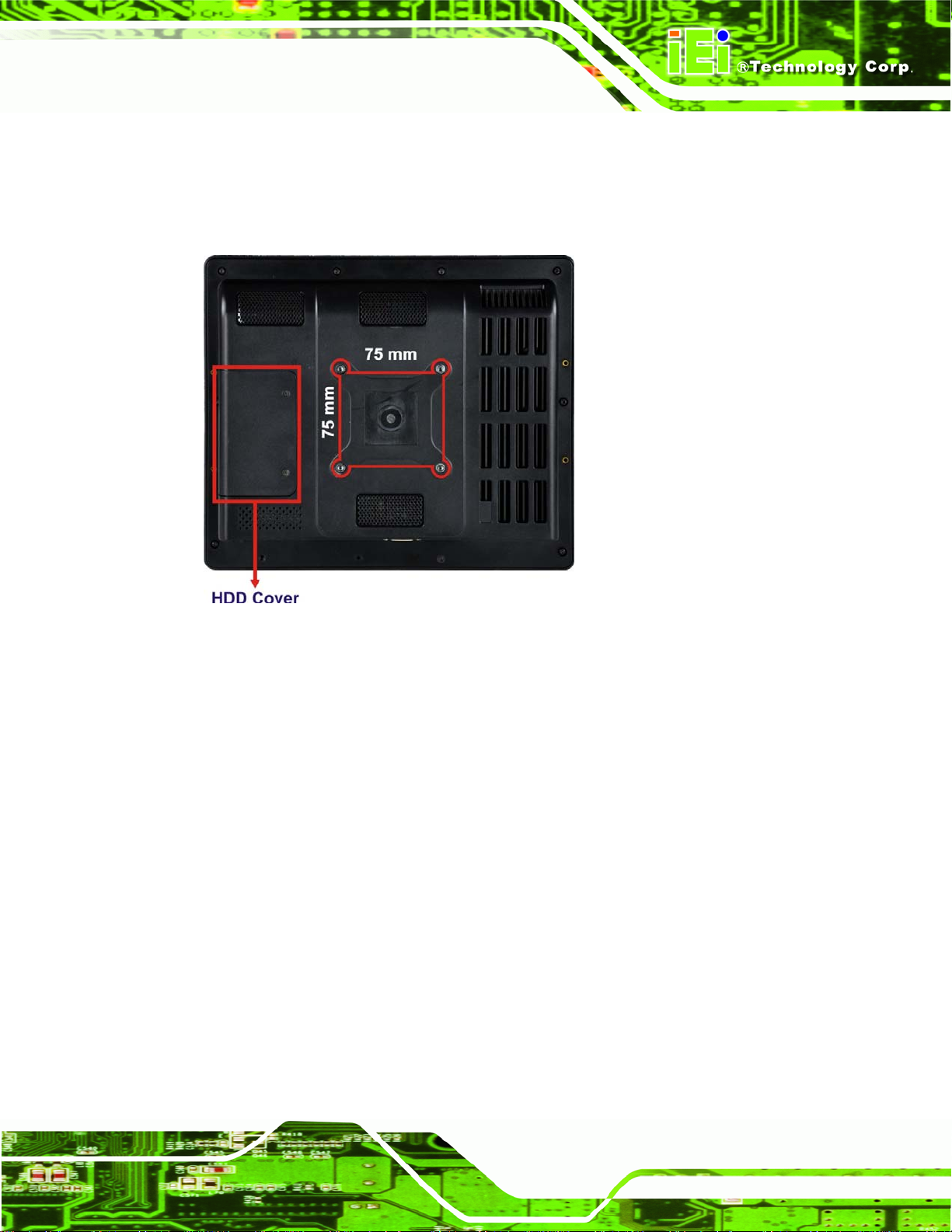
1.2.2 Rear Panel
The rear panel provides access to retention screw holes that support VESA mounting. The
HDD bay is protected by the HDD cover. Refer to
Figure 1-5: Rear View
Figure 1-5.
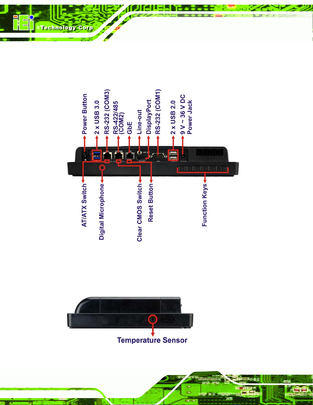
1.2.3 Bottom Panel
The bottom panel of the AFL2-10A-N28 has the following connectors and switches
(
Figure 1-6):
1 x 9 V ~ 36 V DC input power jack
1 x Audio line-out jack
1 x AT/ATX switch
1 x Clear CMOS switch
1 x DisplayPort connector
6 x Function keys
1 x GbE RJ-45 connector
1 x Digital microphone
1 x Power button
1 x Reset button
1 x RS-232 DB-9 connector (COM1)
Page 7
Page 25
AFL2-10A-N28 Panel PC
1 x RS-232 RJ-45 connector (COM3)
1 x RS-422/485 RJ-45 connector
2 x USB 2.0 connectors
2 x USB 3.0 connectors
Figure 1-6: Bottom Panel
1.2.4 Left Side Panel
The left side panel of the AFL2-10A-N28 has a temperature sensor (Figure 1-7).
Page 8
Figure 1-7: Left Side Panel
Page 26
AFL2-10A-N28 Panel PC
1.3 Internal Overview
The AFL2-10A-N28 has the following components installed internally:
1 x Motherboard
1 x 2.0 GB 1066 MHz DDR3 SO-DIMM
1 x 802.11b/g/n wireless LAN module
1.4 System Specifications
The technical specifications for the AFL2-10A-N28 systems are listed in Table 1-4.
Specification AFL2-10A-N28
LCD Size 10.4"
Max. Resolution 800 (W) x 600 (H)
Brightness (cd/m2) 400
Contrast Ratio 700:1
LCD Color 262K/16.2M
Pixel Pitch (H x V) (mm) 0.264 (H) x 0.264 (V)
Viewing Angle (H-V) 160° / 140°
Backlight LED backlight (MTBF: 30,000 hrs)
Touchscreen 5-Wire resistive type touch screen
CPU 1.86 GHz Intel® Atom™ N2800 dual-core processor
Chipset Intel® NM10
Ethernet Realtek RTL8111E PCIe GbE controller support ASF2.0
Memory Preinstalled one 204-pin 1066 MHz 2 GB DDR3 SO-DIMM (max. 4 G)
HDD 2.5" SATA 3Gb /s HDD bay
Audio Realtek ALC892 HD Audio codec (Line-out)
Speaker AMP 1.5 W + 1.5 W (built-in stereo speakers)
Camera 2-megapixel camera with low light function
Microphone Digital microphone located on the bottom of the front frame
Wireless 1 x Wireless LAN 802.11 b/g/n module (PCIe Mini card)
Bluetooth Optional internal USB interface, Bluetooth V2.0+EDR
RFID Reader EM 125 KHz or MIFARE 13.56 MHz card reader (optional)
MSR Card Reader MSR card reader (optional)
Page 9
Page 27
AFL2-10A-N28 Panel PC
OSD Function LCD on/off, brightness up/down, volume up/down, Hot Key
Construction Material PC+ABS plastic front frame
Mounting VESA 75 mm x 75 mm (Panel, Wall, Rack, Stand or Arm)
Front Panel Color Black
Weight (N/G) 2.98 kg / 4.5 kg
Dimensions (W x H x D) 282.5 mm x 242.7 mm x 51.0 mm
Operating Temperature -20ºC ~ 45ºC
Storage Temperature -20ºC ~ 60ºC
Humidity 10% ~ 95% (no-condensing)
IP level IP 64 compliant front panel
Power Supply 65 W power adapter
Input: 100 V AC ~ 240 V AC @ 50 / 60 Hz
Output: 19 V DC
Power Requirement 9 V ~ 36 V DC
Power Consumption 19 V @ 1.6 A (Intel® Atom™ N2800 CPU with 2 GB DDR3 memory)
Safety/EMC CE, FCC
I/O Ports and Switches 1 x RS-232 (DB-9 connector)
1 x RS-232 (RJ-45 connector)
1 x RS-422/485 (RJ-45 connector)
1 x GbE LAN (RJ-45 connector)
2 x USB 2.0 connectors
2 x USB 3.0 connectors
1 x Mini USB 2.0 connector (on front panel)
1 x microSD card slot (on front panel)
1 x Audio line-out jack
1 x DisplayPort connector
1 x Power switch
1 x AT/ATX switch
1 x Reset button
1 x Clear CMOS button
1 x 9 V ~ 36 V DC input jack
Table 1-3: System Specifications
Page 10
Page 28
AFL2-10A-N28 Panel PC
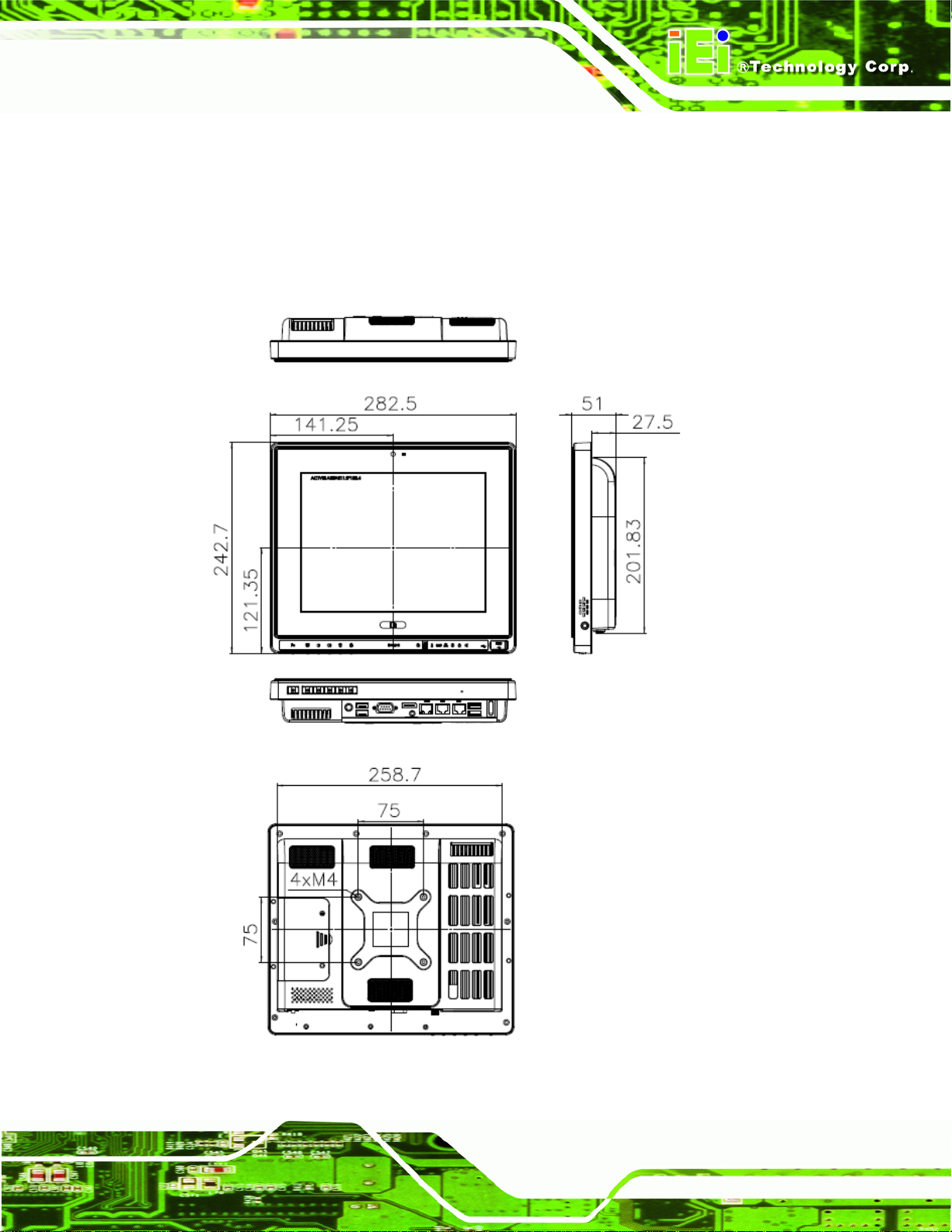
1.5 Dimensions
The AFL2-10A-N28 dimensions are shown below.
Width: 282.5 mm
Height: 242.7 mm
Depth: 51.0 mm
Figure 1-8: AFL2-10A-N28 Dimensions (mm)
Page 11
Page 29
AFL2-10A-N28 Panel PC
Chapter
2
2 Unpacking
Page 12
Page 30
AFL2-10A-N28 Panel PC
2.1 Unpacking
To unpack the flat bezel panel PC, follow the steps below:
WARNING!
The front side LCD screen has a protective plastic cover stuck to the
screen. Only remove the plastic cover after the flat bezel panel PC has
been properly installed. This ensures the screen is protected during the
installation process.
Step 1: Use box cutters, a knife or a sharp pair of scissors that seals the top side of the
external (second) box.
Step 2: Open the external (second) box.
Step 3: Use box cutters, a knife or a sharp pair of scissors that seals the top side of the
internal (first) box.
Step 4: Lift the monitor out of the boxes.
Step 5: Remove both polystyrene ends, one from each side.
Step 6: Pull the plastic cover off the flat bezel panel PC.
Step 7: Make sure all the components listed in the pa cking list are present. Step 0:
2.1.1 Packing List
The AFL2-10A-N28 flat bezel panel PC is shipped with the following components:
Page 13
Page 31

AFL2-10A-N28 Panel PC
Quantity Item Image
Standard
1 AFL2-10A-N28 panel PC
1 Power adapter
(P/N: 63040-010060-030-RS)
1 Power cord
(P/N: 32702-000401-100-RS)
1 Power transfer cord
(P/N: 32702-000300-100-RS)
1 RJ-45 to DB-9 COM Port Cable
(P/N: 32005-000200-200-RS)
1 Pen for resistive touchscreen
(P/N: 43125-0002C0-00-RS)
4 M3*4 flat head screw pack for HDD installation
(P/N: 44013-030041-RS)
4 M4*6 pan head screw pack for VESA mount
(P/N: 44403-040061-RS)
1 Utility CD
Page 14
1 One Key Recovery CD
(P/N: 7B000-000724-RS)
Page 32

AFL2-10A-N28 Panel PC
Optional
Wall mounting kit
(P/N: AFL WK-12)
Panel mounting kit
(P/N: AFL2PK-10A)
Rack mounting kit
(P/N: AFL2RK-10A)
Stand
(P/N: STAND-C12/ STAND-B19)
Stand
(P/N: VSTAND-A10)
Hybrid card reader
(P/N: AFL2P-12AMSI-U-R10)
Magnetic stripe reader
(P/N: AFL2P-12AMSR-U-R10)
Bluetooth module kit
(P/N: AFL2-BT-KIT01-R11)
OS: Win CE 6.0 (CD-ROM)
(P/N: AFL2-W10A-CV-CE 060-R10)
Page 15
Page 33

AFL2-10A-N28 Panel PC
OS: Win XPE (CD-ROM)
(P/N: AFL2-W10A-CV-XP E-R10)
OS: Linux (CD-ROM)
(P/N: AFL2-W10A-CV-L NX-R10)
OS: Win 7 Embedded (DVD-ROM)
(P/N: AFL2-W10A-CV-WES7P-R1 0 or
AFL2-W10A-CV-WES7E-R10)
If any of these items are missing or damaged, contact the distributor or sales
representative immediately.
Page 16
Page 34

AFL2-10A-N28 Panel PC
3 Installation
Chapter
3
Page 17
Page 35

AFL2-10A-N28 Panel PC
3.1 Anti-static Precautions
WARNING:
Failure to take ESD precautions during the maintenance of the
AFL2-10A-N28 may result in permanent damage to the AFL2-10A-N28
and severe injury to the user.
Electrostatic discharge (ESD) can cause serious damage to electronic components,
including the AFL2-10A-N28. Dry climates are especially susceptible to ESD. It is
therefore critical that whenever the AFL2-10A-N28 is accessed internally, or any other
electrical component is handled, the following anti-static precautions are strictly adhered
to.
Wear an anti-static wristband: - Wearing a simple anti-static wristband can
help to prevent ESD from damaging the board.
Self-grounding: - Before handling the board touch any grounded conducting
material. During the time the board is handled, frequently touch any
conducting materials that are connected to the ground.
Use an anti-static pad: - When configuring the AFL2 -10A-N28, place it on an
antic-static pad. This reduces the possibility of ESD damaging the
AFL2-10A-N28.
Only handle the edges of the PCB: - When handling the PCB, hold the PCB
by the edges.
3.2 Installation Precautions
When installing the flat bezel panel PC, please follow the precautions listed below:
Power turned off: When installing the flat bezel panel PC, make sure the
power is off. Failing to turn off the power may cause severe injury to the body
and/or damage to the system.
Page 18
Certified Engineers: Only certified engineers should install and modify
onboard functionalities.
Page 36

AFL2-10A-N28 Panel PC
Anti-static Discharge : If a user open the rear p anel of the flat bezel panel PC,
to configure the jumpers or plug in added peripheral devices, ground
themselves first and wear an anti-static wristband.
3.3 Installation and Configuration Steps
The following installation steps must be followed.
Step 1: Unpack the flat bezel panel PC.
Step 2: Install the HDD.
Step 3: Install the RFID reader. (optional)
Step 4: Configure the system.
Step 5: Connect peripheral devices to the flat bezel panel PC.
Step 6: Mount the flat bezel panel PC. Step 0:
3.4 HDD Installation
WARNING:
Over-tightening back cover screws will crack the plastic frame.
Maximum torque for cover screws is 5 kg-cm (0.36 lb-ft/0.49 Nm).
To install the HDD into the AFL2-10A-N28, please follow the steps below:
Step 1: Remove two (2) retention screws from the HDD cover (
Figure 3-1).
Page 19
Page 37

AFL2-10A-N28 Panel PC
Figure 3-1: HDD Cover Retention Screws
Step 2: Remove the HDD cover from the device.
Step 3: Loosen the captive screw to release the HDD bracket from the chassis. Slide the
HDD bracket out of the device as shown (
Figure 3-2).
Page 20
Figure 3-2: HDD Bracket Removal
Step 4: Insert an HDD into the bracket as shown in
Figure 3-3.
Page 38

AFL2-10A-N28 Panel PC
Figure 3-3: Inserting the HDD
Step 5: Secure the HDD to the bracket using four (4) M3*4 retention screws (two screws
on each side) (
Figure 3-4: Securing the HDD
Step 6: Slide the HDD module back into the device.
Figure 3-4).
Step 7: Tighten the captive screw.
Step 8: Replace the HDD cover and secure it using two (2) retention screws. Step 0:
Page 21
Page 39

AFL2-10A-N28 Panel PC
3.5 RFID Reader Installation (Optional)
An optional RFID reader can be installed in the AFL2-10A-N28. To install the RFID reader,
follow the instructions below.
Step 1: Remove a total of eleven (11) retention screws from the back cover (
Figure 3-5).
Figure 3-5: Back Cover Retention Screws
Step 2: Remove the five (5) retention screws securing the internal cover to the chassis
Figure 3-6).
(
Page 22
Figure 3-6: Internal Cover Retention Screws
Page 40

AFL2-10A-N28 Panel PC
Step 3: Using two retention screws to install the RFID reader module in the location
shown in
Figure 3-7.
Figure 3-7: RFID Reader Module Installation
Step 4: Connect the RFID module to the RFID connector on the main board (
3-8). The RFID connector pinouts are listed in Section
7.2.17.
Figure
Step 5: Place the RFID antenna on the location shown in
antenna to the RFID antenna connector on the RFID module.
Figure 3-8: RFID Reader Connection
Figure 3-8. Connect the RFID
Page 23
Page 41

AFL2-10A-N28 Panel PC
Step 6: Replace the internal cover and back cover using previously removed retention
screws. Step 0:
3.6 AT/ATX Mode Selection
AT or ATX power mode can be used on the AFL2-10A-N28. The selection is made
through an AT/ATX switch located on the bottom panel. To select AT mode or ATX mode,
follow the steps below.
Step 1: Locate the AT/ATX switch on the bottom panel (
Figure 3-9).
Figure 3-9: AT/ATX Switch Location
Step 2: Adjust the AT/ATX switch. Step 0:
3.6.1 AT Power Mode
With the AT mode selected, the power is controlled by a central power unit rather than a
power switch. The AFL2-10A-N28 panel PC turns on automatically when the power is
connected. The AT mode benefits a production line to control multiple panel PCs from a
central management center and other applications including:
ATM
Self-service kiosk
Plant environment monitoring system
Factory automation platform
Manufacturing shop flow
3.6.2 ATX Power Mode
With the ATX mode selected, the AFL2-10A-N28 panel PC goes in a standby mode when
it is turned off. The panel PC can be easily turned on via network or a power switch in
standby mode. Remote power control is perfect for advertising applications since the
Page 24
Page 42

AFL2-10A-N28 Panel PC
broadcasting time for each panel PC can be set individually and cont rolled remotely . Other
possible application includes
Security surveillance
Point-of-Sale (POS)
Advertising terminal
3.7 Clear CMOS
If the AFL2-10A-N28 fails to boot due to improper BIOS settings, the clear CMOS switch
clears the CMOS data and resets the system BIOS information. To do this, adjust the
clear CMOS switch to clear CMOS mode for a few seconds then adjust the clear CMOS
switch back to keep CMOS mode.
Step 1: Locate the clear CMOS switch on the bottom panel (
Figure 3-10: Clear CMOS Switch Location
Step 2: Adjust the clear CMOS switch. Step 0:
3.8 Reset the System
The reset button enables user to reboot the system when the system is turned on. To
reboot the system, follow the steps below.
Step 1: Locate the reset button on the bottom panel (
Figure 3-10).
Figure 3-11).
Figure 3-11: Reset Button Location
Page 25
Page 43
AFL2-10A-N28 Panel PC
Step 2: Press the reset button. Step 0:
3.9 Powering On the System
To power on the system, follow the steps below:
Step 1: Locate the Function and Brightness Up function keys. See Section
Step 2: Hold down the Function and Brightness Up buttons for six seconds to power on
the system. Step 0:
3.10 Powering Off the System
To power off the system, follow the steps below:
Step 1: Locate the Function and Brightness Up function keys. See Section
Step 2: Hold down the Function and Brightness Up buttons for six seconds to power off
the system. Step 0:
3.11 Mounting the System
WARNING:
1.2.1.2.
1.2.1.2.
Page 26
When mounting the flat bezel panel PC onto an arm, onto the wall or
onto a panel, it is better to have more than one person to help with the
installation to make sure the panel PC does not fall down and get
damaged.
The five methods of mounting the AFL2-10A-N28 are listed below.
Wall mounting
Panel mounting
Rack mounting
Arm mounting
Stand mounting
Page 44

AFL2-10A-N28 Panel PC
V-Stand mounting
The five mounting methods are described below.
3.11.1 Wall Mounting
To mount the flat bezel panel PC onto the wall, please follow the steps below.
Step 1: Select the location on the wall for the wall-mounting bracket.
Step 2: Carefully mark the locations of the four screw holes in the bracket on the wall.
Step 3: Drill four pilot holes at the marked locations on the wall for the bracket retention
screws.
Step 4: Align the wall-mounting bracket screw holes with the pilot holes.
Step 5: Secure the mounting-bracket to the wall by inserting the retention screws into
the four pilot holes and tightening them (
Figure 3-12).
Figure 3-12: Wall-mounting Bracket
Page 27
Page 45

AFL2-10A-N28 Panel PC
Step 6: Insert the four monitor mounting screws provided in the wall mount kit into the
four screw holes on the real panel of the flat bezel panel PC and tighten until the
screw shank is secured against the rear panel (
Figure 3-13).
WARNING:
Please use the M4 screws provided in the wall mount kit for the rear panel.
If the screw is missing, the thread depth of the replacement screw should
be not more than 4 mm.
Step 7: Align the mounting screws on the monitor rear panel with the mounting holes on
the bracket.
Step 8: Carefully insert the screws through the holes and gently pull the monitor
downwards until the monitor rests securely in the slotted holes (
Ensure that all four of the mounting screws fit snugly into their respective slotted
holes.
Figure 3-13).
NOTE:
In the diagram below the bracket is already installed on the wall.
Page 28
Page 46

AFL2-10A-N28 Panel PC
Figure 3-13: Chassis Support Screws
Step 9: Secure the panel PC by fastening the retention screw of the wall-mounting
bracket. (
Figure 3-14).
Figure 3-14: Secure the Panel PC
Page 29
Page 47

AFL2-10A-N28 Panel PC
3.11.2 Panel Mounting
To mount the AFL2-10A-N28 flat bezel panel PC into a panel, please follow the steps
below.
Step 1: Select the position on the panel to mount the flat bezel panel PC.
Step 2: Cut out a section corresponding to the size shown below. The size must be
smaller then the outer edge.
Figure 3-15: Cutout Dimensions
Step 3: Slide the flat bezel panel PC through the hole until the frame is flush against the
panel.
Step 4: Align the panel mounting bracket screw holes with the VESA mounting holes on
the rear of the panel PC.
Step 5: Secure the two panel mounting brackets to the rear of the panel PC by insertin g
the four retention screws into the VESA mounting holes (
Step 6: Insert the panel mounting clamps into the holes of the panel mounting brackets
Figure 3-16 o). There are a total of 4 panel mounting clamps for
(
AFL2-10A-N28.
Figure 3-16 n).
Page 30
Page 48

AFL2-10A-N28 Panel PC
Step 7: Tighten the screws that pass through the p anel mou nting clamp s u ntil the plastic
caps at the front of all the screws are firmly secured to the panel.
Step 8: Install the covers into the panel mounting bracket. Each mounting bracket
includes two side covers and one top cover (
Figure 3-16 p).
Figure 3-16: Tighten the Panel Mounting Clamp Screws
3.11.3 Cabinet and Rack Installation
The AFL2-10A-N28 flat bezel panel PC can be installed into a cabinet or rack. The
installation procedures are similar to the panel mounting installation. To do this, please
follow the steps below:
Page 31
Page 49

AFL2-10A-N28 Panel PC
NOTE:
When purchasing the cabinet/rack installation bracket, make sure it is
compatible with both the AFL2-10A-N28 flat bezel panel PC and the
rack/cabinet into which the AFL2-10A-N28 is installed.
Step 1: Slide the rear chassis of the AFL2-10A-N28 flat bezel panel PC through the
rack/cabinet bracket until the frame is flush against the front of the bracket
Figure 3-17).
(
Figure 3-17: The Rack/Cabinet Bracket
Step 2: Align the panel mounting bracket screw holes with the VESA mounting holes on
the rear of the panel PC.
Step 3: Secure the two rack mounting brackets to the rear of the panel PC by inserting
the four retention screws into the VESA mounting holes (
Step 4: Insert the rack mounting clamps into the holes of the rack mounting brackets
Figure 3-18 o). There are a total of 4 rack mounting clamps for
(
AFL2-10A-N28.
Step 5: Tighten the screws that pass through the rack mounting clamps until the plastic
caps at the front of all the screws are firmly secured to the panel.
Figure 3-18 n).
Page 32
Page 50

AFL2-10A-N28 Panel PC
Step 6: Install the covers into the rack mounting bracket. Each mounting bracket
includes two side covers and one top cover (
Figure 3-18 p).
Figure 3-18: Secure the Rack/Cabinet Bracket
Step 7: Slide the flat bezel panel PC with the attached rack/cabinet bracket into a rack or
cabinet (
Figure 3-19).
Figure 3-19: Install into a Rack/Cabinet
Page 33
Page 51

AFL2-10A-N28 Panel PC
Step 8: Once the flat bezel panel PC with the attached rack/cabinet bracket has been
properly inserted into the rack or cabinet, secure the front of the rack/cabinet
bracket to the front of the rack or cabinet (
Figure 3-19).
3.11.4 Arm Mounting
The AFL2-10A-N28 is VESA (Video Electronics Standards Association) compliant and can
be mounted on an arm with a 75 mm interface pad. To mount the AFL2-10A-N28 on an
arm, please follow the steps below.
Step 1: The arm is a separately purchased item. Please correctly mount the arm onto
the surface it uses as a base. To do this, refer to the installation documentation
that came with the mounting arm.
NOTE:
When purchasing the arm please ensure that it is VESA compliant and that
the arm has a 75 mm interface pad. If the mounting arm is not VESA
compliant it cannot be used to support the AFL2-10A-N28 flat bezel panel
PC.
Step 2: Once the mounting arm has been firmly attached to the surface, lift the flat bezel
panel PC onto the interface pad of the mounting arm.
Step 3: Align the retention screw holes on the mounting arm interface with those in the
flat bezel panel PC (
Figure 3-20).
Page 34
Page 52

AFL2-10A-N28 Panel PC
Figure 3-20: Arm Mounting Retention Screw Holes
Step 4: Secure the AFL2-10A-N28 to the interface p ad by inserting fou r retention screws
through the mounting arm interface pad and into the AFL2-10A-N28.Step 0:
Figure 3-21: Arm Mounting
Page 35
Page 53
AFL2-10A-N28 Panel PC
3.11.5 Stand Mounting
To mount the AFL2-10A-N28 using the stand mounting kit, please follow the steps below.
Step 1: Locate the screw holes on the rear of the AFL2-10A-N28. This is where the
bracket will be attached.
Step 2: Align the bracket with the screw holes.
Step 3: To secure the bracket to the AFL2-10A-N28 insert the retention screws into the
screw holes and tighten them.Step 0:
Figure 3-22: Stand Mounting (Stand-A/Bxx)
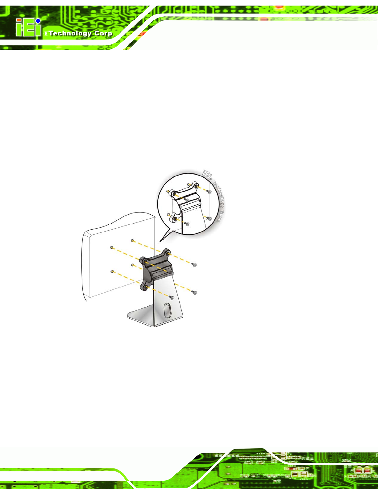
3.11.6 V-Stand Mounting
To mount the AFL2-10A-N28 using the V-Stand mounting kit, please follow the steps
below.
Step 1: Carefully mark the locations of the four V -Stand screw holes on the mounting
area. Drill four pilot holes at the marked locations for the V-Stand retention
screws.
Page 36
Page 54

AFL2-10A-N28 Panel PC
Figure 3-23: Drill Pilot Holes for V-Stand
Step 2: Align the screw holes on the V-Stand with the VESA mount screw holes on the
system rear panel.
Step 3: Insert the four VESA mount screws into the four screw holes on the system rear
panel. Adjust the V-Stand to a proper position.
Step 4: Tighten until the screw shank is se cured against the rear panel.
Figure 3-24: Secure System to V-Stand
Page 37
Page 55

AFL2-10A-N28 Panel PC
Step 5: Align the V-Stand screw holes with the pilot holes on the mounting area. Mount
the V-Stand by inserting the retention screws into the four pilot holes and
tightening them.
Step 6: Adjust the V-Stand to have a best viewing angle to operate the system.Step 0:
Figure 3-25: Secure V-Stand to Mounting Area
3.12 External Peripheral Device Connection
The following external peripheral devices can be connected to the external peripheral
interface connectors.
Audio devices
HDMI devices
RJ-45 Ethernet cable connector
Serial port devices
USB devices
VGA monitor
To install these devices, connect the corresponding cable connector from the actual
Page 38
device to the corresponding AFL2-10A-N28 external peripheral interface connector
making sure the pins are properly aligned.
Page 56

AFL2-10A-N28 Panel PC
3.12.1 Audio Connection
The audio jack on the external audio connector enables the AFL2-10A-N28 to be
connected to a stereo sound setup. To install the audio devices, follow the steps below.
Step 1: Identify the audio plugs. The plugs on your home theater system or speakers
may not match the colors on the rear panel. If audio plugs are plugged into the
wrong jacks, sound quality will be very bad.
Step 2: Plug the audio plug into the audio jack. Plug the audio plug into the audio
jack. If the plug on your speakers is different, an adapter will need to be used to
plug them into the audio jack. The audio jack on the AFL2-10A-N28 is a line-out
port which connects to a headpho ne or a speaker.
Figure 3-26: Audio Connector
Step 3: Check audio clarity. Check that the sound is coming through the right speakers
by adjusting the balance front to rear and left to right.
3.12.2 DisplayPort Connection
The DisplayPort connector transmits a digital signal to compatible DisplayPort display
devices such as a TV or computer screen. To connect the DisplayPort cable to the
AFL2-10A-N28, follow the steps below.
Page 39
Page 57

AFL2-10A-N28 Panel PC
Step 1: Locate the DisplayPort connector. The location is shown in Chapter 3.
Step 2: Align the connector. Align the DisplayPort connector with the DisplayPort port.
Make sure the orientation of the connector is correct.
Figure 3-27: DisplayPort Connection
Step 3: Insert the DisplayPort connector . Gently insert the DisplayPort connector. The
connector should engage with a gentle push. If the connector does not insert
easily , check again that the connector is aligne d correctly, and that the connector
is being inserted with the right way up.
3.12.3 LAN Connection
There is one external RJ-45 LAN connectors The RJ-45 connector enables connection to
an external network. To connect a LAN cable with an RJ-45 connector, please follow the
instructions below.
Step 1: Locate the RJ-45 connector. The location of the LAN connector is shown in
Chapter 1.
Step 2: Align the connectors. Align the RJ-45 connector on the LAN cable with the
RJ-45 connectors on the AFL2-10A-N28. See
Figure 3-28.
Page 40
Page 58
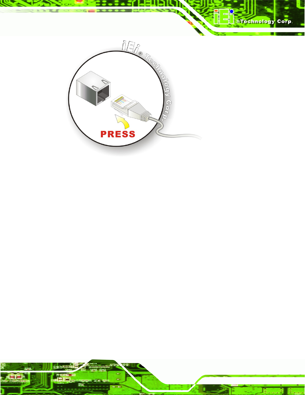
AFL2-10A-N28 Panel PC
Figure 3-28: LAN Connection
Step 3: Insert the LAN cable RJ-45 connector. Once aligned, gently insert the LAN
cable RJ-45 connector into the external interface.
3.12.4 Serial Device Connection
There are two external RS-232 connectors (one by DB-9 and one by RJ-45) and one
RS-422/485 RJ-45 connector for serial device connection. Follow the steps below to
connect a serial device to the AFL2-10A-N28.
3.12.4.1 DB-9 Serial Port Connection
Follow the steps below to connect a serial device to the DB-9 connector of the
AFL2-10A-N28 panel PC.
Step 1: Locate the DB-9 connector. The location of the DB-9 connectors is shown in
Chapter 1.
Step 2: Insert the serial connector. Insert the DB-9 connector of a serial device into
the DB-9 connector on the bottom panel. See
Figure 3-29.
Page 41
Page 59

AFL2-10A-N28 Panel PC
Figure 3-29: DB-9 Serial Port Connector
Step 3: Secure the connector. Secure the serial device connector to the external
interface by tightening the two retention screws on either side of the connector.
3.12.4.2 RJ-45 Serial Port Connection
Follow the steps below to connect a serial device to the RJ-45 serial port connector of the
AFL2-10A-N28 panel PC.
Step 1: Locate the RJ-45 serial port. The location of the RJ-45 serial port is shown in
Chapter 1.
Step 2: Connect the RJ-45 to COM port cable to the panel PC. Insert the RJ-45
connector end of cable into the RJ-45 serial port. See
Step 3: Connect the serial device. Connect a serial device to the DB-9 connector end
Figure 3-30.
Page 42
of the cable. See
Figure 3-30.
Page 60

AFL2-10A-N28 Panel PC
Figure 3-30: RJ-45 Serial Port Connector
Step 4: Secure the connector. Secure the serial device connector to the external
interface by tightening the two retention screws on either side of the connector.
Step 0:
The DB-9 connector pinouts are listed below.
Figure 3-31: DB-9 Connector Pinout Locations
PIN NO. RS-232 RS-422 RS-485
1 DCD RX+ 2 RX RX- 3 TX TX+ DATA+
4 DTR TX- DATA5 GND - 6 DSR - 7 RTS - 8 CTS - 9 RI - -
Table 3-1: DB-9 Connector Pinout
Page 43
Page 61

AFL2-10A-N28 Panel PC
3.12.5 USB Device Connection
NOTE:
User must install the USB 3.0 driver before connecting a USB device to
the system or else the system may not recognize the connected
device.
There are two USB 2.0 connectors and two USB 3.0 connectors on the AFL2-10A-N28. To
connect a USB device, please follow the instructions below.
Step 1: Locate the USB connectors. The locations of the USB connectors are shown
in Chapter 1.
Step 2: Align the connectors. Align the USB device connector with one of the
connectors on the AFL2-1 0A-N28. See
Figure 3-32.
Figure 3-32: USB Device Connection
Page 44
Step 3: Insert the device connector. Once aligned, gently insert the USB device
connector into the onboard connector. Step 0:
Page 62
AFL2-10A-N28 Panel PC
Chapter
4
4 BIOS Setup
Page 45
Page 63
AFL2-10A-N28 Panel PC
4.1 Introduction
A licensed copy of the BIOS is preprogrammed into the ROM BIOS. The BIOS setup
program allows users to modify the basic system configuration. This chapter describes
how to access the BIOS setup program and the configuration options that may be
changed.
4.1.1 Starting Setup
The UEFI BIOS is activated when the computer is turned on. The setup program can be
activated in one of two ways.
1. Press the DEL or F2 key as soon as the system is turned on or
2. Press the DEL or F2 key when the “Press DEL or F2 to enter
SETUP” message appears on the screen. 0.
If the message disappears before the DEL or F2 key is pressed, restart the computer and
try again.
4.1.2 Using Setup
Use the arrow keys to highlight items, press ENTER to select, use the PageUp and
PageDown keys to change entries, press F1 for help and press E
keys are shown in the following table.
Key Function
Up arrow Move to the item above
Down arrow Move to the item below
Left arrow Move to the item on the left hand side
Right arrow Move to the item on the right hand side
+ Increase the numeric value or make changes
- Decrease the numeric value or make changes
SC to quit. Navigation
Page 46
F1 key General help, only for St atus Page Setup Menu and Option
Page Setup Menu
Page 64

AFL2-10A-N28 Panel PC
F2 key Load previous values.
F3 key Load optimized defaults
F4 key Save changes and Exit BIOS
Esc key Main Menu – Quit and do not save changes into CMOS
Status Page Setup Menu and Option Page Setup Menu -Exit current page and return to Main Menu
Table 6-1: BIOS Navigation Keys
4.1.3 Getting Help
When F1 is pressed a small help window describing the appropriate keys to use and the
possible selections for the highlighted item appears. To exit the Help Window press E
the F1 key again.
4.1.4 Unable to Reboot after Configuration Changes
If the computer cannot boot after changes to the system configuration are made, CMOS
defaults.
4.1.5 BIOS Menu Bar
The menu bar on top of the BIOS screen has the following main items:
Main – Changes the basic system configuration.
Advanced – Changes the advanced system settings.
Chipset – Changes the chipset settings.
Boot – Changes the system boot configuration.
Security – Sets User and Supervisor Passwords.
Save & Exit – Selects exit options and loads default settings
SC or
The following sections completely describe the configuration options found in the menu
items at the top of the BIOS screen and listed above.
Page 47
Page 65

AFL2-10A-N28 Panel PC
4.2 Main
The Main BIOS menu (8BIOS Menu 1) appears when the BIOS Setup program is entered.
The Main menu gives an overview of the basic system information.
Aptio Setup Utility – Copyright (C) 2011 American Megatrends, Inc.
Main Advanced Chipset Boot Security Save & Exit
BIOS Information
BIOS Vendor American Megatrends
Core Version 4.6.5.3 0.16
Compliency UEFI 2.3; PI 1.2
Project Version SE25AR12.ROM
Build Date and Time 11/01/2012 14:50:49
iWDD Vendor ICP
iWDD Version SE25ER12.bin
System Date [Fri 01/01/2010]
System Time [13:16:27]
Access Level Administrator
Version 2.14.1219. Copyright (C) 2011 American Megatrends, Inc.
Set the Date. Use Tab to
switch between Data
elements.
----------------------
ÅÆ
↑ ↓: Select Item
Enter Select
+/-: Change Opt.
F1: General Help
F2: Previous Values
F3: Optimized Defaults
F4: Save & Exit
ESC: Exit
: Select Screen
BIOS Menu 1: Main
Î BIOS Information
The BIOS Information lists a brief summary of the BIOS. The fields in BIOS Information
cannot be changed. The items shown in the system overview include:
BIOS Vendor: Installed BIOS vendor
Core Version: Current BIOS version
Compliency: Current compliant version
Project Version: the bo ard version
Build Date and Time: Date the current BIOS version was made
Î iWDD Vendor
The iWDD Vendor displays the installed iWDD vendor. The fields in iWDD
Vendor cannot be changed.
Page 48
Page 66

AFL2-10A-N28 Panel PC
Î iWDD Version
The iWDD Version displays the current iWDD version . The fields in iWDD
Version cannot be changed.
Î System Date [xx/xx/xx]
Use the System Date option to set the system date. Manually enter the day, month and
year.
Î System Time [xx:xx:xx]
Use the System Time option to set the system time. Manually enter the hours, minutes
and seconds.
4.3 Advanced
Use the Advanced menu (8BIOS Menu 2) to configure the CPU and peripheral devices
through the following sub-menus:
WARNING:
Setting the wrong values in the sections below may cause the system
to malfunction. Make sure that the settings made are compatible with
the hardware.
ACPI Settings
RTC Wake Settings
CPU Configuration
SATA Configuration
USB Configuration
F81866 Super IO Configuration
H/W Monitor
Serial Port Console Redirection
iEi Feature
Page 49
Page 67

AFL2-10A-N28 Panel PC
S
Aptio Setup Utility – Copyright (C) 2011 American Megatrends, Inc.
Main Advanced Chipset Boot Security Save & Exit
> ACPI Settings
> RTC Wake Settings
> CPU Configuration
> SATA Configuration
> USB Configuration
> F81866 Super IO Configuration
> H/M Monitor
> Serial Port Console Redirection
> iEi Feature
Version 2.14.1219. Copyright (C) 2011 American Megatrends, Inc.
BIOS Menu 2: Advanced
System ACPI Parameters.
----------------------
ÅÆ
↑ ↓: Select Item
Enter Select
+/-: Change Opt.
F1: General Help
F2: Previous Values
F3: Optimized Defaults
F4: Save & Exit
ESC: Exit
: Select Screen
4.3.1 ACPI Settings
The ACPI Settings menu (8BIOS Menu 3) configures the Advanced Configuration and
Power Interface (ACPI) options.
Aptio Setup Utility – Copyright (C) 2011 American Megatrends, Inc.
Advanced
ACPI Settings
ACPI Sleep State [S1 (CPU Stop Clock)]
Version 2.14.1219. Copyright (C) 2011 American Megatrends, Inc.
elect the highest ACPI
sleep state the system
will enter, when the
SUSPEND button is
pressed.
----------------------
ÅÆ
: Select Screen
↑ ↓: Select Item
Enter Select
+/-: Change Opt.
F1: General Help
F2: Previous Values
F3: Optimized Defaults
F4: Save & Exit
ESC: Exit
BIOS Menu 3: ACPI Configuration
Page 50
Page 68

E
w
AFL2-10A-N28 Panel PC
Î ACPI Sleep State [S1 (CPU Stop Clock)]
Use the ACPI Sleep State option to specify the sleep state the system enters when it is
not being used.
Î
S1 (CPU Stop
Clock)
Î
S3 (Suspend to
RAM)
DEFAULT
The system enters S1 (POS) sleep state. The
system appears off. The CPU is stopped; RAM is
refreshed; the system is running in a low power
mode.
The caches are flushed and the CPU is powered
off. Power to the RAM is maintained. The
computer returns slower to a working state, but
more power is saved.
4.3.2 RTC Wake Settings
The RTC Wake Settings menu (BIOS Menu 4) configures RTC wake event.
Aptio Setup Utility – Copyright (C) 2011 American Megatrends, Inc.
Advanced
Wake system with Fixed Time [Disabled]
Version 2.14.1219. Copyright (C) 2011 American Megatrends, Inc.
nable or disable System
ake on alarm event. When
enabled, System will
wake on the
dat::hr::min::sec
specified
----------------------
ÅÆ
: Select Screen
↑ ↓: Select Item
Enter Select
F1 General Help
F2 Previous Values
F3 Optimized Defaults
F4 Save
ESC Exit
BIOS Menu 4: RTC Wake Settings
Page 51
Page 69

AFL2-10A-N28 Panel PC
Î Wake System with Fixed Time [Disabled]
Use the Wake System with Fixed Time option to specify the time the system should be
roused from a suspended state.
Î
Disabled DEFAULT
Î
Enabled
The real time clock (RTC) cannot generate a wake
event
If selected, the following appears with values that
can be selected:
*Wake up every day
*Wake up date
*Wake up hour
*Wake up minute
*Wake up second
After setting the alarm, the computer turns itself on
from a suspend state when the alarm goes off.
4.3.3 CPU Configuration
Use the CPU Configuration (BIOS Menu 5) to view detailed CPU specifications and
configure the CPU.
Page 52
Page 70

a
T
AFL2-10A-N28 Panel PC
Aptio Setup Utility – Copyright (C) 2011 American Megatrends, Inc.
Advanced
CPU Configuration
Processor Type Intel(R) Atom(TM)
CPU N2800 @ 1.86GHz
EMT64 Supported
Processor Speed 1865 MHz
System Bus Speed 533 MHz
Ratio Status 14
Actual Ratio 14
System Bus Speed 533 MHz
Processor Stepping 30661
Microcode Revision 268
L1 Cache RAM 2x56 k
L2 Cache RAM 2x512 k
Processor Core Dual
Hyper-Threading Supported
Hyper Threading [Enabled]
Version 2.14.1219. Copyright (C) 2011 American Megatrends, Inc.
Enabled for Windows XP
nd Linux (OS optimized
for Hyper-Threading
echnology) and Disabled
for other OS (OS not
optimized for
Hyper-Threading
Technology).
----------------------
ÅÆ
: Select Screen
↑ ↓: Select Item
Enter Select
+/-: Change Opt.
F1: General Help
F2: Previous Values
F3: Optimized Defaults
F4: Save & Exit
ESC: Exit
BIOS Menu 5: CPU Configuration
The CPU Configuration menu (
Processor Type: Lists the brand name of the CPU being used
EMT64: Indicates if EM64T is supported by the CPU.
Processor Speed: Lists the CPU processing speed
System Bus Speed: Lists the system bus speed
Ratio Status: Lists the ratio status
Actual Ratio: Lists the actual ratio
Processor Stepping: Lists the CPU processing stepping
Microcode Revision: Lists the microcode revision
L1 Cache RAM: Lists the amount of storage space o n the L1 Cache
L2 Cache RAM: Lists the amount of storage space o n the L2 Cache
Processor Core: Lists the number of the processor cores
Hyper-Threading: Indicates if Hyper-Threading is supported by the CPU.
BIOS Menu 6) lists the following CPU details:
Î Hyper-Threading [Enabled]
Use the Hyper-Threading option to enable or disable Hyper-Threading Technology on
the system.
Page 53
Page 71

AFL2-10A-N28 Panel PC
Î
Disabled
Î
Enabled DEFAULT
Disables Hyper-Threading Technology
Enables Hyper-Threading Technology
4.3.4 SATA Configuration
Use the SATA Configuration menu (BIOS Menu 6) to change and/or set the
configuration of the SATA devices installed in the system.
Aptio Setup Utility – Copyright (C) 2011 American Megatrends, Inc.
Advanced
SATA Port0 Not Present
SATA Port1 Not Present
Configure SATA as [IDE]
(1) IDE Mode. (2) AHCI
Mode. (3) RAID Mode.
---------------------
ÅÆ
: Select Screen
↑ ↓: Select Item
Enter Select
+/-: Change Opt.
F1 General Help
F2 Previous Values
F3 Optimized Defaults
F4 Save & Exit
ESC Exit
Version 2.14.1219. Copyright (C) 2011 American Megatrends, Inc.
BIOS Menu 6: SATA Configuration
Î Configure SATA as [IDE]
Use the Configure SATA as option to configure SATA devices as normal IDE devices.
Î
IDE DEFAULT
Î
AHCI
The SATA drive connected to the nth SATA drive port is
Configures SATA devices as normal IDE device.
specified as a normal SATA drive.
Page 54
Page 72

d
AFL2-10A-N28 Panel PC
4.3.5 USB Configuration
Use the USB Configuration menu (BIOS Menu 7) to read USB configuration information
and configure the USB settings.
Aptio Setup Utility – Copyright (C) 2011 American Megatrends, Inc.
Advanced
USB Configuration
USB Devices:
1 Keyboard, 1 Hub
Legacy USB Support [Enabled]
Version 2.14.1219. Copyright (C) 2011 American Megatrends, Inc.
Enables Legacy USB
support. AUTO option
isables legacy support
if no USB devices are
connected. DISABLE
option will keep USB
devices available only
for EFI applications.
---------------------
ÅÆ
: Select Screen
↑ ↓: Select Item
Enter Select
+/-: Change Opt.
F1: General Help
F2: Previous Values
F3: Optimized Defaults
F4: Save & Exit
ESC: Exit
BIOS Menu 7: USB Configuration
Î USB Devices
The USB Devices Enabled field lists the USB devices that are enabled on the system
Î Legacy USB Support [Enabled]
Use the Legacy USB Support BIOS option to enable USB mouse and USB keyboard
support. Normally if this option is not enabled, any attached USB mouse or USB keyboard
does not become available until a USB compatible operating system is fully booted with all
USB drivers loaded. When this option is enabled, any attached USB mouse or USB
keyboard can control the system even when there is no USB driver loaded onto the
system.
Î
Enabled DEFAULT
Legacy USB support enabled
Page 55
Page 73
AFL2-10A-N28 Panel PC
S
Î
Disabled
Î
Auto
Legacy USB support disabled
Legacy USB support disabled if no USB devices are
connected
4.3.6 F81866 Super IO Configuration
Use the F81866 Super IO Configuration menu (BIOS Menu 8) to set or change the
configurations for the serial ports.
Aptio Setup Utility – Copyright (C) 2011 American Megatrends, Inc.
Advanced
F81866 Super IO Configuration
F81866 Super IO Chip F81866
> Serial Port 1 Configuration
> Serial Port 2 Configuration
> Serial Port 3 Configuration
Version 2.14.1219. Copyright (C) 2011 American Megatrends, Inc.
et Parameters of Serial
Port 1 (COMA)
---------------------
ÅÆ
: Select Screen
↑ ↓: Select Item
Enter Select
+/-: Change Opt.
F1: General Help
F2: Previous Values
F3: Optimized Defaults
F4: Save & Exit
ESC: Exit
Page 56
BIOS Menu 8: Super IO Configuration
Page 74
E
AFL2-10A-N28 Panel PC
4.3.6.1 Serial Port n Configuration
Use the Serial Port n Configuration menu (BIOS Menu 9) to configure the serial port n.
Aptio Setup Utility – Copyright (C) 2011 American Megatrends, Inc.
Advanced
Serial Port 1 Configuration
Serial Port [Enabled]
Device Settings IO=3F8h; IRQ=4
Change Settings [Auto]
Version 2.14.1219. Copyright (C) 2011 American Megatrends, Inc.
nable or Disable Serial
Port (COM)
---------------------
ÅÆ
: Select Screen
↑ ↓: Select Item
Enter Select
+/-: Change Opt.
F1: General Help
F2: Previous Values
F3: Optimized Defaults
F4: Save & Exit
ESC: Exit
BIOS Menu 9: Serial Port n Configuration Menu
4.3.6.1.1 Serial Port 1 Configuration
Î Serial Port [Enabled]
Use the Serial Port option to enable or disable the serial port.
Î
Disabled
Î
Enabled DEFAULT
Î Change Settings [Auto]
Use the Change Settings option to change the serial port IO port address and interrupt
address.
Î
Auto DEFAULT
Disable the serial port
Enable the serial port
The serial port IO port address and interrupt
address are automatically detected.
Î
IO=3F8h; IRQ=4
Serial Port I/O port address is 3F8h and the
interrupt address is IRQ4
Page 57
Page 75

AFL2-10A-N28 Panel PC
Î
IO=2F8h; IRQ=3
4.3.6.1.2 Serial Port 2 Configuration
Î Serial Port [Enabled]
Use the Serial Port option to enable or disable the serial port.
Î
Disabled
Î
Enabled DEFAULT
Î Change Settings [Auto]
Use the Change Settings option to change the serial port IO port address and interrupt
address.
Î
Auto DEFAULT
Serial Port I/O port address is 2F8h and the
interrupt address is IRQ3
Disable the serial port
Enable the serial port
The serial port IO port address and interrupt
Î
IO=2F8h; IRQ=3
Î
IO=3F8h; IRQ=4
Î Device Mode [RS422/485]
Use the Device Mode option to select the serial port mode.
Î
RS422/485 DEFAULT
4.3.6.1.3 Serial Port 3 Configuration
Î Serial Port [Enabled]
Use the Serial Port option to enable or disable the serial port.
address are automatically detected.
Serial Port I/O port address is 2F8h and the
interrupt address is IRQ3
Serial Port I/O port address is 3F8h and the
interrupt address is IRQ4
Enables serial port RS-422/485 support.
Page 58
Page 76

AFL2-10A-N28 Panel PC
Î
Disabled
Î
Enabled DEFAULT
Î Change Settings [Auto]
Use the Change Settings option to change the serial port IO port address and interrupt
address.
Î
Auto DEFAULT
Î
IO=3E8h; IRQ=10
Î
Î
IO=3E8h;
IRQ=10,11
IO=2E8h;
IRQ=10,11
Disable the serial port
Enable the serial port
The serial port IO port address and interrupt
address are automatically detected.
Serial Port I/O port address is 3E8h and the
interrupt address is IRQ10
Serial Port I/O port address is 3E8h and the
interrupt address is IRQ10, 11
Serial Port I/O port address is 2E8h and the
interrupt address is IRQ10, 11
Î
Î
IO=2F0h;
IRQ=10,11
IO=2E0h;
IRQ=10,11
Serial Port I/O port address is 2F0h and the
interrupt address is IRQ10, 11
Serial Port I/O port address is 2E0h and the
interrupt address is IRQ10, 11
Page 59
Page 77
AFL2-10A-N28 Panel PC
4.3.7 H/W Monitor
The H/W Monitor menu (BIOS Menu 10) shows the operating temperature.
Aptio Setup Utility – Copyright (C) 2011 American Megatrends, Inc.
Advanced
CPU temperature :+37 °C
System temperature :+36 °C
Environment Temperature :+30 °C
Version 2.14.1219. Copyright (C) 2011 American Megatrends, Inc.
---------------------
ÅÆ
: Select Screen
↑ ↓: Select Item
Enter Select
+/-: Change Opt.
F1: General Help
F2: Previous Values
F3: Optimized Defaults
F4: Save & Exit
ESC: Exit
BIOS Menu 10: Hardware Health Configuration
Î Hardware Health Status
The following system parameters and values are shown. The system parameters that are
monitored are:
CPU Temperature
System Temperature
Environment Temperature
4.3.8 Serial Port Console Redirection
The Serial Port Console Redirection menu (BIOS Menu 14) allows the console
redirection options to be configured. Console redirection allows users to maintain a
system remotely by re-directing keyboard input and text output through the serial port.
Page 60
Page 78
AFL2-10A-N28 Panel PC
Aptio Setup Utility – Copyright (C) 2011 American Megatrends, Inc.
Advanced
COM1
Console Redirection [Disabled]
> Console Redirection Settings
COM3
Console Redirection [Disabled]
> Console Redirection Settings
Version 2.14.1219. Copyright (C) 2011 American Megatrends, Inc.
BIOS Menu 11: Serial Port Console Redirection
Î Console Redirection [Disabled]
Console Redirection
Enable or Disable.
---------------------
ÅÆ
: Select Screen
↑ ↓: Select Item
Enter Select
+/-: Change Opt.
F1: General Help
F2: Previous Values
F3: Optimized Defaults
F4: Save & Exit
ESC: Exit
Use Console Redirection option to enable or disable the console redirection fun ction.
Î
Disabled DEFAULT
Î
Enabled
Disabled the console redirection function
Enabled the console redirection function
Page 61
Page 79
AFL2-10A-N28 Panel PC
s
4.4 iEi Feature
Use the iEi Feature menu (BIOS Menu 15) to configure the auto recovery function.
Aptio Setup Utility – Copyright (C) 2011 American Megatrends, Inc.
Advanced
iEi Feature
Auto Recovery Function [Disabled]
Micro SD Card [Enabled]
Version 2.14.1219. Copyright (C) 2011 American Megatrends, Inc.
Auto Recovery Function
Reboot and recover
system automatically
within 10 min, when OS
crashes. Please install
Auto Recovery API
ervice before enabling
this function
---------------------
ÅÆ
: Select Screen
↑ ↓: Select Item
Enter Select
+/-: Change Opt.
F1: General Help
F2: Previous Values
F3: Optimized Defaults
F4: Save & Exit
ESC: Exit
BIOS Menu 12: iEi Feature
Î Auto Recovery Function [Disabled]
Use the Auto Recovery Function option to enable or disable auto recovery on the
system.
Î
Disabled DEFAULT
Î
Enabled
Î Micro SD Card [Enabled]
Use the Micro SD Card option to enable or disable the microSD card slot function on the
front panel. Disable the microSD function first before running the auto recovery function.
Î
Disabled
Î
Enabled DEFAULT
Auto Recovery Function support disabled
Auto Recovery Function support enabled
microSD function disabled
microSD function enabled
Page 62
Page 80

AFL2-10A-N28 Panel PC
4.5 Chipset
Use the Chipset menu (BIOS Menu 16) to access the North Bridge, South Bridge, and
Integrated Graphics configuration menus.
WARNING!
Setting the wrong values for the Chipset BIOS selections in the Chipset
BIOS menu may cause the system to malfunction.
Aptio Setup Utility – Copyright (C) 2011 American Megatrends, Inc.
Main Advanced Chipset Boot Security Save & Exit
> Host Bridge
> South Bridge
Host Bridge Parameters
---------------------
ÅÆ
↑ ↓: Select Item
Enter Select
+ - Change Opt.
F1 General Help
F2 Previous Values
F3 Optimized Defaults
F4 Save & Exit
ESC Exit
: Select Screen
Version 2.14.1219. Copyright (C) 2011 American Megatrends, Inc.
BIOS Menu 13: Chipset
Page 63
Page 81

AFL2-10A-N28 Panel PC
S
w
d
4.5.1 Host Bridge Configuration
Use the Host Bridge menu (BIOS Menu 17) to configure the host bridge chipset.
Aptio Setup Utility – Copyright (C) 2011 American Megatrends, Inc.
Chipset
> Intel IGD Configuration
******* Memory Information *******
Memory Frequency 1067 Mhz (DDR3)
Total Memory 1024 MB
DIMM#1 1024 MB
Version 2.14.1219. Copyright (C) 2011 American Megatrends, Inc.
Config Intel IGD
Settings
---------------------
ÅÆ
: Select Screen
↑ ↓: Select Item
Enter Select
+ - Change Opt.
F1 General Help
F2 Previous Values
F3 Optimized Defaults
F4 Save & Exit
ESC Exit
BIOS Menu 14: Northbridge Chipset Configuration
4.5.1.1 Internal IGD Configuration
Use the Internal IGD Configuration (BIOS Menu 15) menu to set the integrated graphics.
Aptio Setup Utility – Copyright (C) 2011 American Megatrends, Inc.
Chipset
Internal IGD Configuration
IGFX – Boot Type [VBIOS Default]
LCD Panel Type [800x600-18BIT]
Active LFP [Int-LVDS]
Fixed Graphics Memory Size [128MB]
Version 2.14.1219. Copyright (C) 2011 American Megatrends, Inc.
elect the Video Device
hich will be activated
uring POS. This has no
effect if external
graphics present.
---------------------
ÅÆ
: Select Screen
↑ ↓: Select Item
Enter Select
+ - Change Opt.
F1 General Help
F2 Previous Values
F3 Optimized Defaults
F4 Save & Exit
ESC Exit
BIOS Menu 15: Internal IGD Configuration
Page 64
Page 82

AFL2-10A-N28 Panel PC
Î IGFX - Boot Type [VBIOS Default]
Use the IGFX – Boot Type option to select the display device used by the system when it
boots. Configuration option is listed below.
VBIOS Default D
Î LCD Panel Type [800x600-1 8BIT]
Use the LCD Panel Type option to select the type of flat panel connected to the system.
Configuration option is listed below.
800x600-18BIT D
Î Active LFP [Int-LVDS]
Use the Active LFP option to select the Active LFP configuration.
Î
Int-LVDS DEFAULT
Î Fixed Graphics Memory Size [128 MB]
Use the Fixed Graphics Memory Size option to specify the maximum amount of memory
that can be allocated as graphics memory. Configuration options are listed below.
EFAULT
EFAULT
BIOS enables LVDS. Driven by integrated encoder.
128MB Default
256MB
4.5.2 South Bridge Configuration
Use the South Bridge menu (BIOS Menu 18) to configure the Southbridge chipset.
Page 65
Page 83

AFL2-10A-N28 Panel PC
Aptio Setup Utility – Copyright (C) 2011 American Megatrends, Inc.
Chipset
Auto Power Button Status [OFF]
WIFI Function [Enabled]
DMIC Function [Enabled]
Blue Tooth Function [Enabled]
Power Saving Function [Disabled]
Restore AC Power Loss [Last State]
Version 2.14.1219. Copyright (C) 2011 American Megatrends, Inc.
BIOS Menu 16: South Bridge Configuration
Î WIFI Function [Enabled]
WIFI Function
---------------------
ÅÆ
: Select Screen
↑ ↓: Select Item
Enter Select
+ - Change Opt.
F1 General Help
F2 Previous Values
F3 Optimized Defaults
F4 Save & Exit
ESC Exit
Use the WIFI Function option to enable or disable the Wi-Fi function.
Î
Disabled
Î
Enabled DEFAULT
Î DMIC Function [Enabled]
Use the DMIC Function option to enable or disable the digital microphone.
Î
Disabled
Î
Enabled DEFAULT
Î Blue Tooth Function [Enabled]
Use the Blue Tooth Function option to enable or disable the Bluetooth function. This
option shows only when a Bluetooth module is installed in the system.
Î
Disabled
Wi-Fi function disabled
Wi-Fi function enabled
Digital microphone disabled
Digital microphone enabled
Bluetooth disabled
Page 66
Î
Enabled DEFAULT
Bluetooth enabled
Page 84

AFL2-10A-N28 Panel PC
Î Power Saving Function [Disabled]
Use the Power Saving Function BIOS option to enable or disable the power saving
function.
Î
Disabled DEFAULT
Î
Enabled
Î Restore on AC Power Loss [Last State]
Use the Restore on AC Power Loss BIOS option to specify what state the system
returns to if there is a sudden loss of power to the system.
Î
Power Off
Î
Power On
Î
Last State DEFAULT
Power saving function is disabled.
Power saving function is enabled. It will reduce power
consumption when the system is off.
4.6 Boot
Use the Boot menu (BIOS Menu 21) to configure system boot options.
The system remains turned off
The system turns on
The system returns to its previous state. If it was on, it
turns itself on. If it was off, it remains off.
Aptio Setup Utility – Copyright (C) 2011 American Megatrends, Inc.
Main Advanced Chipset Boot Security Save & Exit
Boot Configuration
Bootup NumLock State [On]
Quiet Boot [Enabled]
Launch PXE OpROM [Disabled]
Option ROM Messages [Force BIOS]
UEFI Boot [Disabled]
Boot Option Priorities
Version 2.14.1219. Copyright (C) 2011 American Megatrends, Inc.
BIOS Menu 17: Boot
Select the keyboard
NumLock state
---------------------
ÅÆ
↑ ↓: Select Item
Enter Select
+/-: Change Opt.
F1: General Help
F2: Previous Values
F3: Optimized Defaults
F4: Save & Exit
ESC: Exit
: Select Screen
Page 67
Page 85

AFL2-10A-N28 Panel PC
Î Bootup NumLock State [On]
Use the Bootup NumLock State BIOS option to specify if the number lock setting must
be modified during boot up.
Î
On DEFAULT
Î
Off
Î Quiet Boot [Enabled]
Use the Quiet Boot BIOS option to select the screen display when the system boots.
Allows the Number Lock on the keyboard to be
enabled automatically when the computer system
boots up. This allows the immediate use of the
10-key numeric keypad located on the right side of
the keyboard. To confirm this, the Number Lock LED
light on the keyboard is lit.
Does not enable the keyboard Number Lock
automatically. To use the 10-keys on the keyboard,
press the Number Lock key located on the upper
left-hand corner of the 10-key pad. The Number
Lock LED on the keyboard lights up when the
Number Lock is engaged.
Î
Disabled
Î
Enabled DEFAULT
Î Launch PXE OpROM [Disabled]
Use the Launch PXE OpROM option to enable or disable boot option for legacy network
devices.
Î
Disabled DEFAULT
Î
Enabled
Î Option ROM Messages [Force BIOS]
Use the Option ROM Messages option to set the Option ROM display mode.
Page 68
Normal POST messages displayed
OEM Logo displayed instead of POST messages
Ignore all PXE Option ROMs
Load PXE Option ROMs
Page 86

S
AFL2-10A-N28 Panel PC
Î
Force
BIOS
Î
Keep
Current
Î UEFI Boot [Disabled]
Use the UEFI Boot BIOS option to enable or disable UEFI boot.
Î
Enabled
Î
Disabled DEFAULT
4.7 Security
DEFAULT
Sets display mode to force BIOS.
Sets display mode to current.
Enable UEFI boot if the 1
HDD.
Disable UEFI boot.
st
boot device is a GPT
Use the Security menu (BIOS Menu 22) to set system and user passwords.
Aptio Setup Utility – Copyright (C) 2011 American Megatrends, Inc.
Main Advanced Chipset Boot Security Save & Exit
Password Description
If ONLY the Administrator’s password is set,
then this only limits access to Setup and is
only asked for when entering Setup
If ONLY the User’s password is set, then this
is a power on password and must be entered to
boot or enter Setup. In Setup the User will
have Administrator rights.
The password must be 3 to 20 characters long.
Administrator Password
User Password
Version 2.14.1219. Copyright (C) 2011 American Megatrends, Inc.
BIOS Menu 18: Security
Î Administrator Password
et Setup Administrator
Password
---------------------
ÅÆ
↑ ↓: Select Item
Enter Select
+/-: Change Opt.
F1: General Help
F2: Previous Values
F3: Optimized Defaults
F4: Save & Exit
ESC: Exit
: Select Screen
Use the Administrator Password field to set or change an administrator password.
Page 69
Page 87

AFL2-10A-N28 Panel PC
Î User Password
Use the User Password field to set or change a user password.
4.8 Save & Exit
Use the Save & Exit menu (BIOS Menu 19) to load default BIOS values, optimal failsafe
values and to save configuration changes.
Aptio Setup Utility – Copyright (C) 2011 American Megatrends, Inc.
Main Advanced Chipset Boot Security Save & Exit
Save Changes and Reset
Discard Changes and Reset
Restore Defaults
Save as User Defaults
Restore User Defaults
Version 2.14.1219. Copyright (C) 2011 American Megatrends, Inc.
Reset the system after
saving the changes.
---------------------
ÅÆ
↑ ↓: Select Item
Enter Select
+/-: Change Opt.
F1: General Help
F2: Previous Values
F3: Optimized Defaults
F4: Save & Exit
ESC: Exit
: Select Screen
BIOS Menu 19: Exit
Î Save Changes and Reset
Use the Save Changes and Reset option to save the changes made to the BIOS options
and reset the system.
Î Discard Changes and Reset
Use the Discard Changes and Reset option to exit the system without saving the
changes made to the BIOS configuration setup program.
Î Restore Defaults
Use the Restore Defaults option to load the optimal default values for each of the
parameters on the Setup menus. F3 key can be used for this operation.
Page 70
Page 88

AFL2-10A-N28 Panel PC
Î Save as User Defaults
Use the Save as User Defaults option to save the changes done so far as user defaults.
Î Restore User Defaults
Use the Restore User Defaults option to restore the user defaults to all the setup options.
Page 71
Page 89

AFL2-10A-N28 Panel PC
Chapter
5
5 Software Drivers
Page 72
Page 90

AFL2-10A-N28 Panel PC
5.1 Available Software Drivers
NOTE:
The content of the CD may vary throughout the life cycle of the product
and is subject to change without prior notice. Visit the IEI website or
contact technical support for the latest updates.
The following drivers can be installed on the system:
Chipset
Graphic
Touch
Audio
LAN
USB 3.0
Wi-Fi
Bluetooth
Camera
Installation instructions are given below.
5.2 Starting the Driver Program
To access the driver installation programs, please do the following.
Step 1: Insert the CD-ROM that came with the system into a CD-ROM drive attached to
the system.
Step 2: Click AFL2-10A-N28 Driver.
Step 3: A list of available drivers appears.Step 0:
Page 73
Page 91

AFL2-10A-N28 Panel PC
Figure 5-1: Drivers
5.3 Chipset Driver Installation
To install the chipset driver, please do the following.
Step 1: Access the driver list. (See Section
Step 2: Click “Chipset.”
Step 3: Locate the setup file and double click on it.
Step 4: The setup files are extracted as shown in
5.2)
Figure 5-2.
Page 74
Page 92

AFL2-10A-N28 Panel PC
Figure 5-2: Chipset Driver Screen
Step 5: When the setup files are completely extracted the Welcome Screen in
5-3 appears.
Step 6: Click Next to continue.
Figure 5-3: Chipset Driver Welcome Screen
Figure
Step 7: The license agreement in
Step 8: Read the License Agreement.
Figure 5-4 appears.
Page 75
Page 93
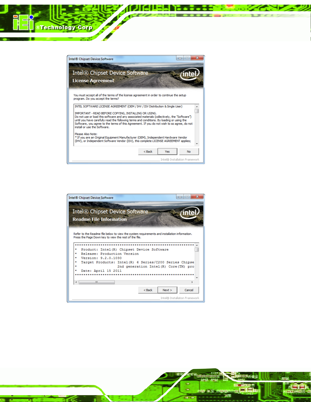
AFL2-10A-N28 Panel PC
Step 9: Click Yes to continue.
Figure 5-4: Chipset Driver License Agreement
Step 10: The Read Me file in
Figure 5-5: Chipset Driver Read Me File
Step 11: Click Next to continue
Figure 5-5 appears.
Page 76
Step 12: Once the setup process is complete, click Finish.
Page 94
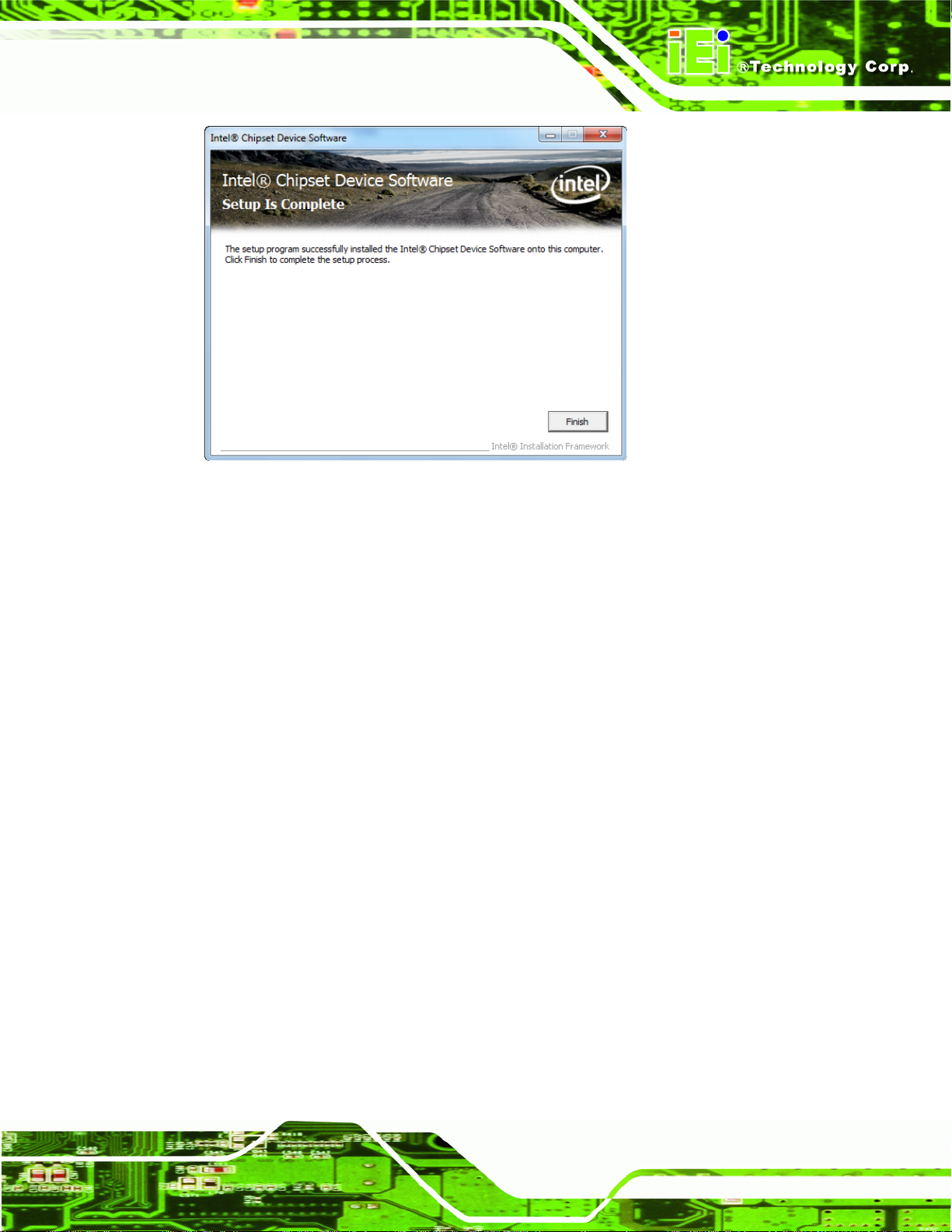
AFL2-10A-N28 Panel PC
Figure 5-6: Chipset Driver Setup Operations
5.4 Graphics Driver Installation
To install the Graphics driver, please do the following.
Step 1: Access the driver list. (See Section
Step 2: Click “Graphic” and select the folder which corresponds to your operating
system.
Step 3: Double click the setup file.
Step 4: The Welcome Screen in
Step 5: Click Next to continue.
Figure 5-7 appears.
5.2)
Page 77
Page 95
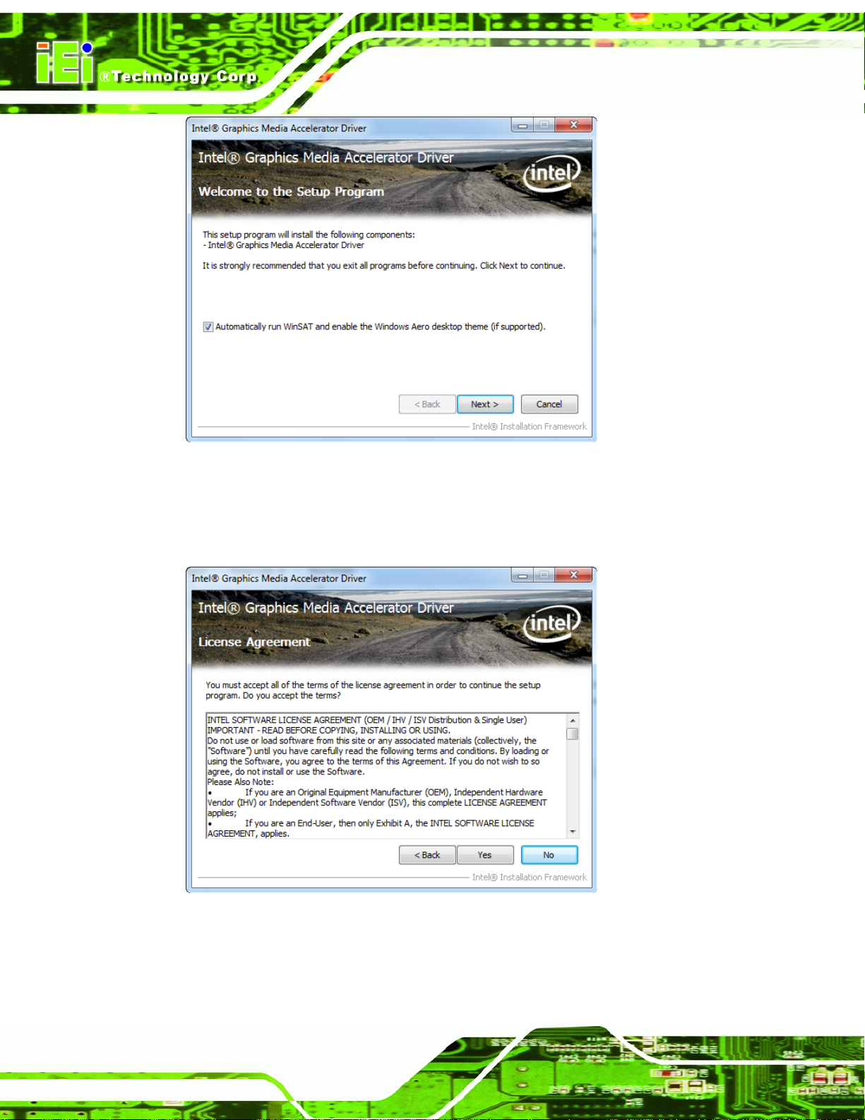
AFL2-10A-N28 Panel PC
Figure 5-7: Graphics Driver Welcome Screen
Step 6: The License Agreement in
Step 7: Click Yes to accept the agreement and continue.
Figure 5-8: Graphics Driver License Agreement
Figure 5-8 appears.
Page 78
Step 8: The Read Me file in
Step 9: Click Next to continue.
Figure 5-9 appears.
Page 96

AFL2-10A-N28 Panel PC
Figure 5-9: Graphics Driver Read Me File
Step 10: Setup Operations are performed as shown in
Step 11: Once the Setup Operations are complete, click Next to continue.
Figure 5-10: Graphics Driver Setup Operations
Figure 5-10.
Step 12: The Finish Screen in
Step 13: Select “Yes, I want to restart this computer now” and click Finish.Step 0:
Figure 5-11 appears.
Page 79
Page 97

AFL2-10A-N28 Panel PC
Figure 5-11: Graphics Driver Installation Finish Screen
5.5 Touch Screen Driver
To install the touch panel software driver, please follow the steps below.
Step 1: Access the driver list. (See Section
Step 2: Click “Touch”.
Step 3: Locate the setup file and double click on it.
Step 4: A Welcome Screen appears (
Step 5: Click N
EXT to continue.
5.2)
Figure 5-12).
Page 80
Page 98

AFL2-10A-N28 Panel PC
Figure 5-12: Touch Screen Driver Welcome Screen
Step 6: The License Agreement shown in
Step 7: Click I
AGREE to accept and continue.
Figure 5-13 appears.
Figure 5-13: Touch Screen Driver License Agreement
Step 8: Browse for an install location or use the one suggested (
Step 9: Click I
NSTALL to continue.
Figure 5-14).
Page 81
Page 99

AFL2-10A-N28 Panel PC
Figure 5-14: Touch Screen Driver Choose Install Location
Step 10: The Install screen a ppears and displays the progress of the installation (
5-15).
Step 11: Click N
EXT to continue.
Figure
Page 82
Figure 5-15: Touch Screen Driver Installation Screen
Step 12: When the installation is complete, click F
INISH to exit setup. (Figure 5-16).
Page 100

AFL2-10A-N28 Panel PC
Figure 5-16: Touch Screen Driver Update Complete
5.5.1 Calibrating the Touch Screen
To calibrate the touch screen cursor with the motion of the touch screen pen (or finger),
please follow the steps below:
Step 1: Make sure the touch screen driver is properly installed .
Step 2: Locate the PenMount Monitor icon in the bottom right corner of the screen.
Figure 5-17: PenMount Monitor Icon
Step 3: Click the icon. A pop up menu appears. See
Figure 5-18.
Page 83
 Loading...