

Page 1
SMART-70X
User Manual
( Laser Engraver )
1
Page 2

Copyright Notice
Users must respect the copyright laws applicable in their country. This manual must not be
photocopied, translated, reproduced or transmitted in whole or in part for any reason and by
the means that might be, albeit electronic or mechanical, without the express, written
authorization of IDP Corp., LTD.
All information contained herein may be subject to modification without prior notice. IDP Corp.,
Ltd. accepts no liability for any possible errors herein, nor for any accidental damage or damage
caused through the dissemination or the use of this manual.
Trademarks
SMART-70X is a trademark and IDP is a registered trademark of IDP Corp., LTD. Windows is
registered trademark of Microsoft Corp. All other trademarks or registered trademarks are marks
of their respective holders. SMART-70 Design is a trademark of IDP Corp., Ltd.
Return Materials Authorization
In order to make a warranty claim you must contact an IDP Reseller. You will be responsible for
packaging the printer for shipment and the costs of shipping and insurance of the printer from
the point of use of the printer to the IDP Reseller. The IDP Reseller will bear the costs of
shipping and insuring the printer from the repair location to the address from which the printer
was shipped.
Before returning any equipment for in-warranty or out-of warranty repair, contact an IDP
Reseller or an IDP Service Center for a Return Materials Authorization (RMA) number.
Repack the equipment in the original packing material and mark the RMA number clearly on
the outside of the box. For more information about RMA or IDP warranty statements, refer to
the Warranty booklet on the quick install guide.
2
Page 3

Table of Contents
1. Basic Information ........................................................................................................................................................ 4
1.1. SMART-70X Overview ................................................................................................................................ 4
1.2. SMART-70X Features .................................................................................................................................. 5
1.3. Caution ............................................................................................................................................................... 8
2. SMART0-70X Installation........................................................................................................................................ 9
2.1. Driver Installation ......................................................................................................................................... 9
2.2. Stand-alone installation .......................................................................................................................... 11
2.3. Installation with the SMART-70P ....................................................................................................... 13
3. Engraving a card ....................................................................................................................................................... 17
3.1. LaserTest .......................................................................................................................................................... 17
3.2. SmartID ............................................................................................................................................................ 18
4. Utilities ............................................................................................................................................................................ 20
4.1. LaserConfig .................................................................................................................................................... 20
4.2. LaserFirmware ............................................................................................................................................... 24
4.3. LaserCam ......................................................................................................................................................... 25
4.4. LaserTest .......................................................................................................................................................... 27
5. Specification ................................................................................................................................................................ 29
3
Page 4
1. Basic Information
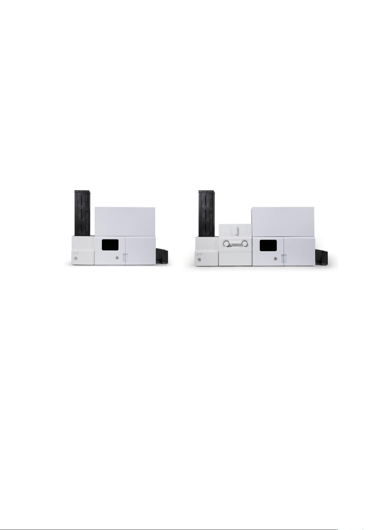
(a) SMART-70IX (b) SMART-70IPX
1.1. SMART-70X Overview
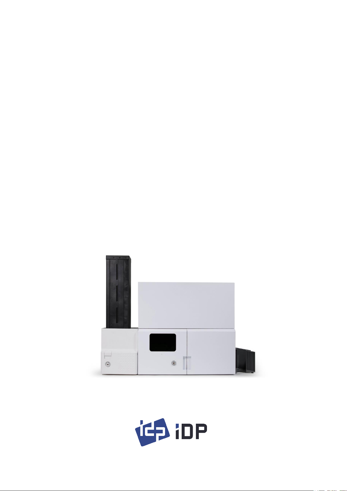
SMART-70X is a device to engrave a card on both sides by laser. SMART-70X is used
independently or with other modules of SMART-70 series.
Picture 1 (a) shows a combination of SMART-70I(Input Hopper) and SMART-70X(Laser
Engraver) for encoding and laser engraving. Picture 1 (b) shows a combination of
SMART-70I(Input Hopper), SMART-70P(Printer) and SMART-70X(Laser Engraver) for
printing, encoding and laser engraving.
Picture 1. Example of combination for SMART-70X
Key features of SMAR-70X are as follows.
Enable a fast and stable engraving with a high quality laser source.
Enable CLI (Changeable Laser Image) engraving.
The Camera inside the module for monitoring and Image Processing is installed by
default.
Enable to encode a magnetic stripe, contact/contactless smart card as options.
The error card drawer to collect encoding failed cards is
installed by default.
The physical key is installed to prevent touching a card.
Enable to use it with SMART-70 Laminator and Output hopper.
4
Page 5
1.2. SMART-70X Features
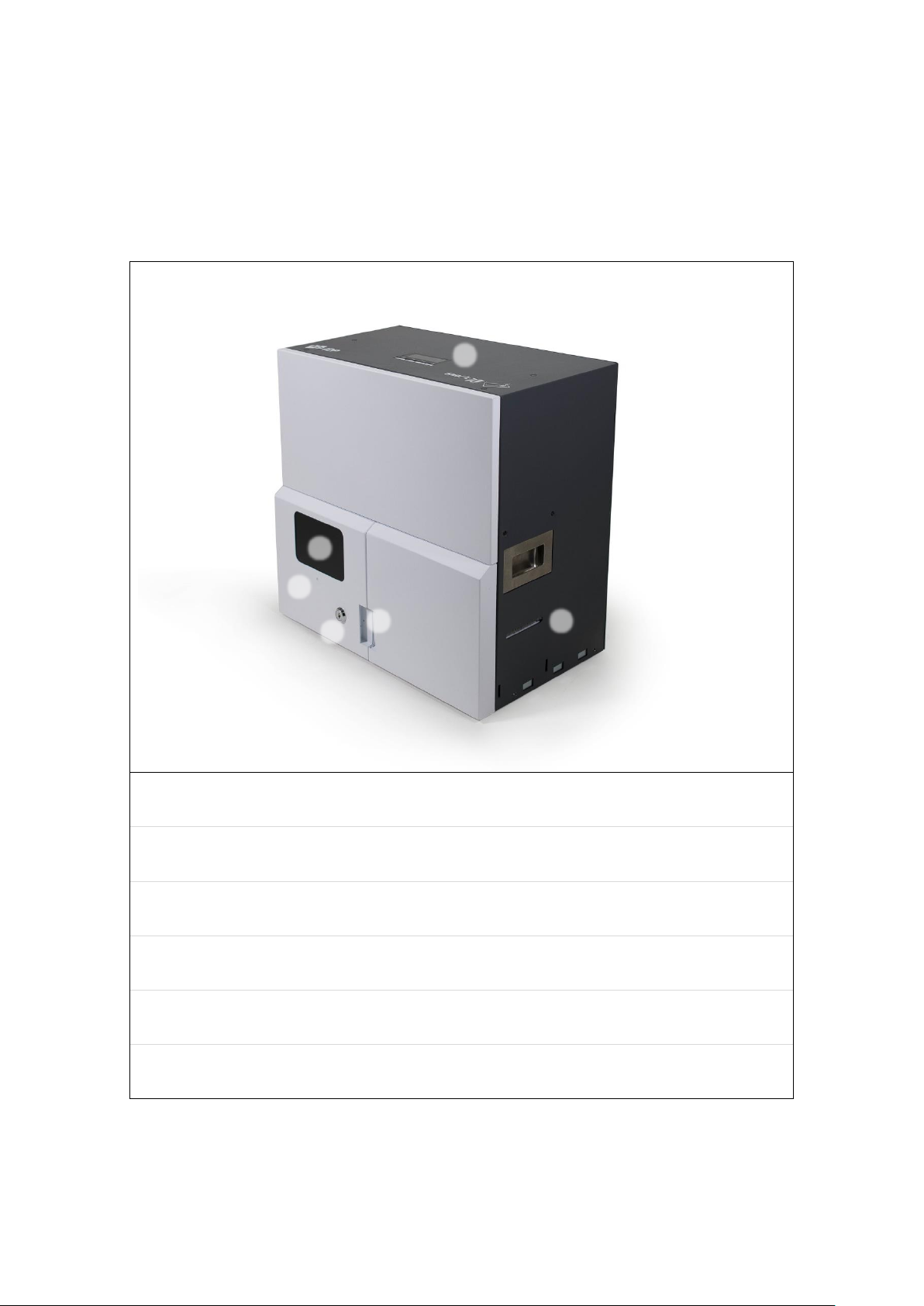
① Control Panel LCD
The status of engraver is displayed. It can be operated by buttons.
② Window for monitoring
It shows operation by eye.
③ Indicator LED
It shows the simple status of module. (Blue: Ready, Green: Operating, Red: Error)
④ Physical lock
To lock engraver
⑤ Door handle
To open a door
⑥ Card Gate
Card gate is to eject cards
⑥
1) External features (Front)
①
③
②
④
⑤
5
Page 6
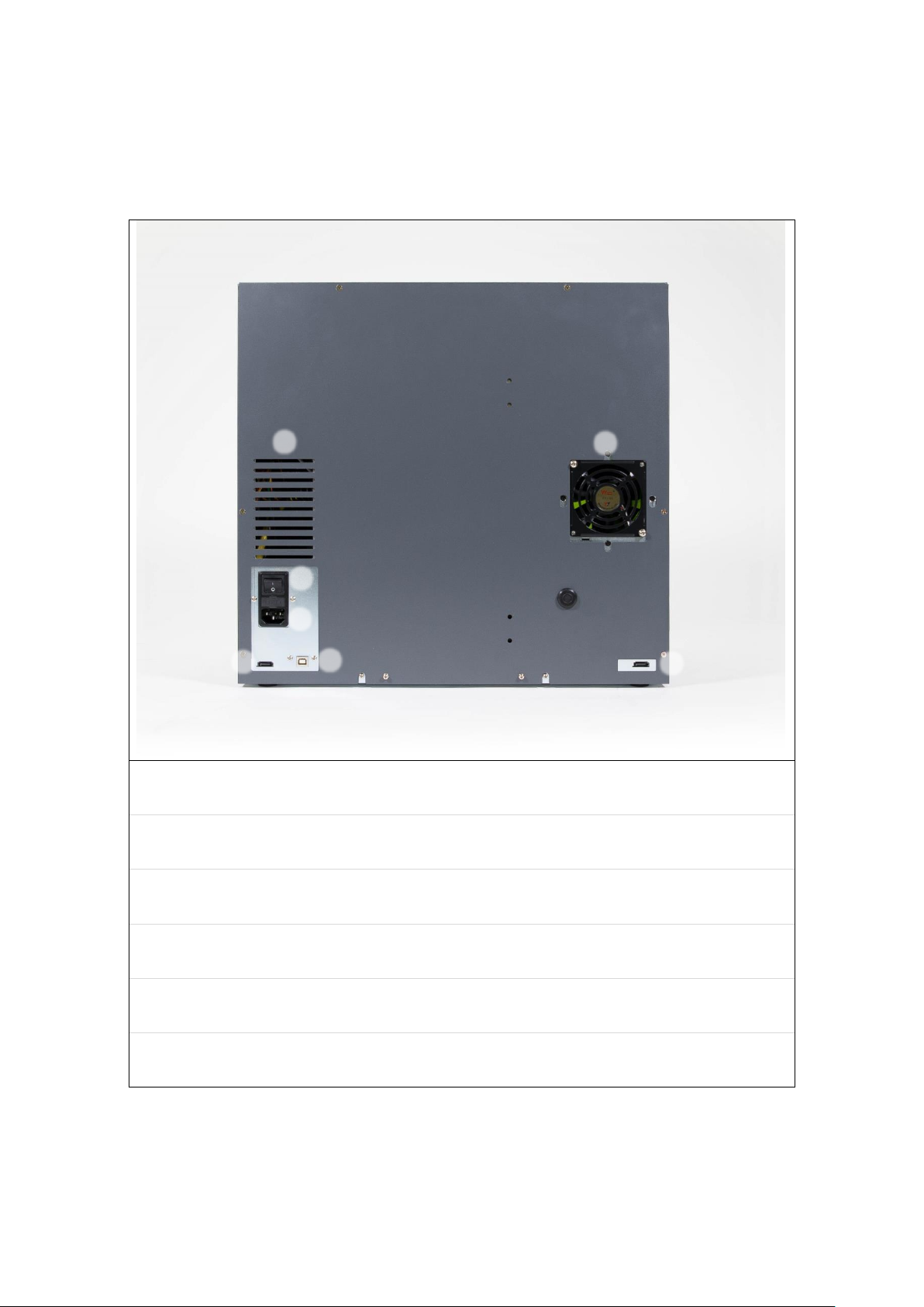
① Air Inlet
The hole which air is inhaled
② Air Outlet
The hole which air is exhaled
③ Power Switch
Turn On/Off
④ Power Plug
110-240V~ 50-60Hz Power plug
⑤,⑦ Communication Port
To communicate between SMART-70 modules
⑥ USB Device port
This port is connected to the PC
⑥
⑦
2) External features (Rear)
①
②
③
④
⑤
6
Page 7
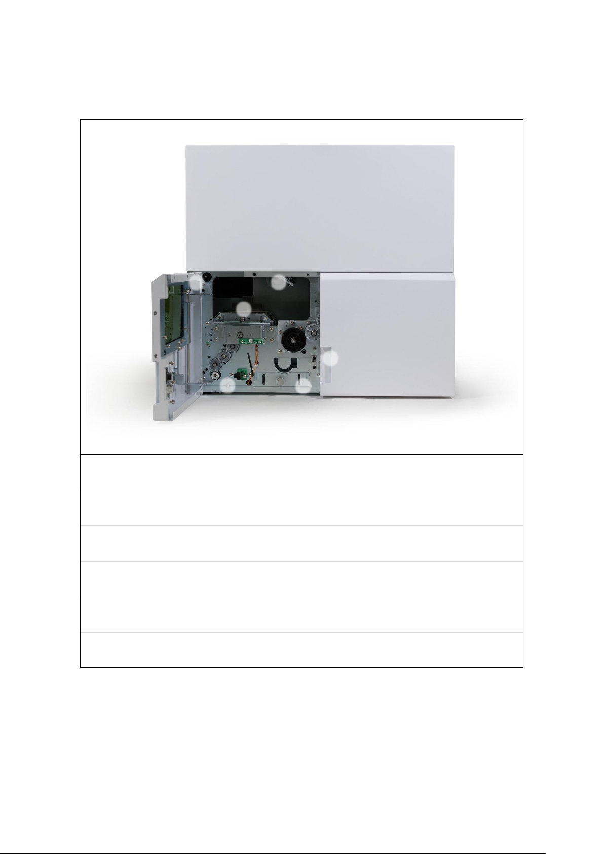
3) Internal features
① Laser safety switch
When a door is opened, it blocks a power of laser for safety.
② Camera
It can check a graving
③ Flipper
It flip a card for engraving on both surfaces
④ Card movement module
It moves a card. The encoder options are installed.
⑤ Door Open Sensor
It can sense opening a door.
⑥ Error card drawer
It keeps error cards.
⑥
①
②
③
④
⑤
7
Page 8
1.3. Caution
Use a power of AC 100~240V, 5~60Hz electric outlet. Otherwise, the
device may have a fault or cause fire.
Do not strike or apply strong vibration to the device. Otherwise, the
device may have a fault or cause fire.
Do not use the device in a dusty place, or in a place with high
temperature. Otherwise, the device may have a fault or cause fire.
Do not expose the device to rain or water. If the device gets wet,
contact an authorized dealer or service center.
Do not push any objects into the air vents or openings of your
equipment. Otherwise, the device may have a fault or cause fire.
Do not connect or disconnect any cable while the device is ON.
Otherwise, the device may have a fault or cause fire.
Do not push a laser safety switch while the door is opened.
Otherwise, the device cause burns or vision problem.
Do not disassemble or modify the device. Otherwise, the device may
have a fault or cause electric shock.
Leave 20.4 cm (8 in) minimum of clearance on all vented sides of the
device to permit the airflow required for proper ventilation.
Restricting airflow can damage the device or cause fire.
Irritating or poisonous gas may be produced depending on a
material of a card. Ventilate the room well or install a ventilator.
If device does not operate normally - in particular, if there are any
unusual sounds or smoke coming from it – turn off it immediately
and contact an authorized dealer or service center.
Before moving, disconnect the power cord and all external
connections
8
Page 9
2. SMART0-70X Installation
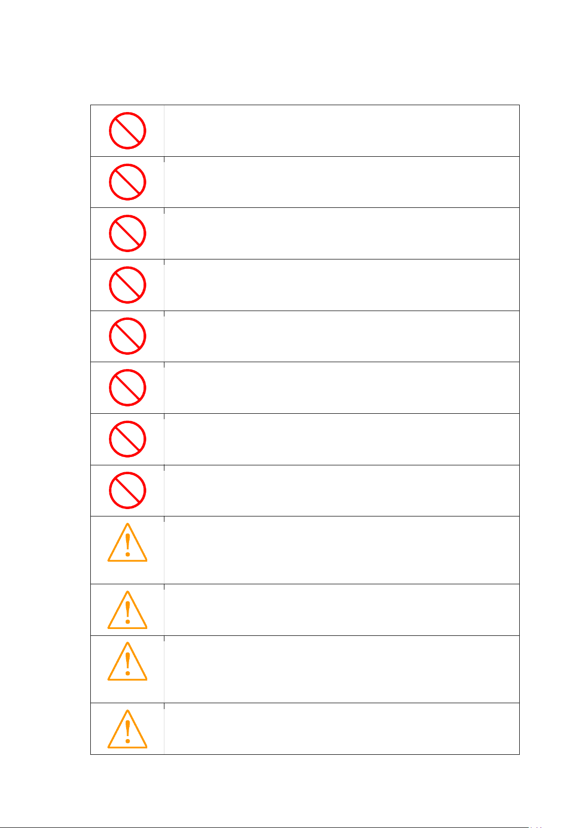
Please run the
‘LaserInstall.exe’ in the
‘SMART-70X\Drivers\’
without connection of
SMART-70X.
STEP 1: Click “Next” button.
STEP 2: Click “Next” button.
2.1. Driver Installation
SMART-70X contains the laser controller, card movement controller and web cam. The
related device driver should be installed in the PC. SMART-70X provides a one-time
installation program for easy driver installation of all components. Please install them as
following the below steps.
1) Run LaserInstall.exe
2) Start Installation of drivers
9
Page 10

3) Confirm a “Windows Security”
Click “Install” button when
“Windows Security”
windows is displayed.
STEP 3: Installation is
completed. Click “Close”
button.
4) Complete drivers
10
Page 11

2.2. Stand-alone installation
After install a binder below
a SMART-70X, connect a
SMART-70I on the binder.
Attach a stacker on the
right side of the SMART70X and arrange modules.
Please connect a SMART-70I input hopper and SMART-70X as a below pictures for laser
engraving only.
5) Connection between SMART-70X and SMART-70I
6) Arrangement of modules
11
Page 12

7) Connection of cables
Connect power cables, red
communication cable and
USB cable as a left picture.
① Connect a 100~240V,
50~60Hz AC power to
SMART-70X, a 24V DC
adapter to SMART-70I.
② Connect the red
communication cables to
each module.
③ Connect each USB cable to
SMART-70X, and connect
the opposite end to the PC.
Turn on the power in order
of the below steps.
① Turn on SMART-70X.
② Turn on SMART-70I.
All modules are installed
normally if the colors of
status LED are blue.
8) Power on
①
①
③
②
①
②
9) Completion of installation
12
Page 13

2.3. Installation with the SMART-70P
After install a binder below
a SMART-70X, connect a
SMART-70P on the binder.
After install a binder below
a SMART-70P, connect a
SMART-70I on the binder.
Please connect a SMART-70I input hopper, SMART-70P printer and SMART-70X as a
below pictures for printing and laser engraving.
1) Connection between SMART-70X and SMART-70P
2) Connection between SMART-70P and SMART-70I
13
Page 14

3) Arrangement of modules
Attach a stacker on the
right side of the SMART70X and arrange modules.
Connect power cables, red
communication cables and
USB cables as a left picture.
① Connect a 100~240V,
50~60Hz AC power to
SMART-70X, a 24V DC
adapter to SMART-70P/I.
② Connect the red
communication cables to
each module.
③ Connect each USB cable to
SMART-70X and SMART70P, and connect the
opposite end to the PC.
③
4) Connection of cables
①
②
③
①
①
②
14
Page 15

5) Power on
Turn on the power in order
of the below steps.
③ Turn on SMART-70X.
④ Turn on SMART-70P.
⑤ Turn on SMART-70I.
Change mode of SMART-70P
to ‘Slave’.
① Click Menu( ) button and
find “System Config.” Menu.
② Click Select ( ) button,
then the ‘Combination’ is
displayed.
③ Click Arrow ( ) button
and find “Operation Mode”.
④ Click Select ( ) button to
change a Mode.
⑤ Click Arrow ( ) button to
change a Mode to “SLAVE”.
⑥ Click Select ( ) button to
apply Mode to “SLAVE”,
and the SMART-70P is
rebooted automatically.
⑦ “Printer Ready” is displayed
on LCD panel if the “SLAVE”
Mode is applied.
6) Change Mode of SMART-70P
①
②
③
15
Page 16

7) Completion of installation
All modules are installed
normally if the colors of
status LED are blue.
16
Page 17

3. Engraving a card
1) The left window is
displayed when running
LaserTest.
2) Check a “Printing &
Engraving” item and click
the ‘Select’ button to
select a
“sample_single.csd”.
3) Click “Run”.
4) The card is inserted
automatically when the
input hopper is
connected. If the
SMART-70X uses a
stand-alone mode, the
user input a card
manually.
3.1. LaserTest
LaserTest is a testing utility for SMART-70X.
Please run LaserTest in the ‘\SMART-70X\Utilities\’ folder.
Please read the “4.4 LaserTest” for reference.
Please use the SmartID for editing a CSD file or creating a new CSD file. Please refer to
the ‘SmartID user manual’.
17
Page 18

3.2. SmartID
The left window is
displayed when running
SmartID.
The ‘Laser’ button is in
the Option tab. Click it to
activate a SMART-70X.
SmartID is a card printing program for SMART series printers. Please run the SmartID
after the installation of SmartID in the Installation CD.
Please refer to the ‘SmartID user manual’ for further information.
SmartID uses the encoders in the printer only.
Please use the LaserTest Utility if the encoder is used in the laser module.
1) Run SmartID
2) Activation of laser function
18
Page 19

3) Design a card
Design a card after
clicking “Front page” of
‘Page’.
You can open a “sample_
single.csd” in the Utilities
folder, too.
Design engraved objects
after clicking “Front page”
of ‘Page 2’.
You can open a “sample_
single.csd” in the Utilities
folder, too.
The preview window is
displayed when clicking
“Print” button. The above
preview is for printing,
and the below preview is
for engraving. To print
and engrave, click “Print”
button in the preview
window.
4) Design engraved objects
5) Engrave a card
19
Page 20

4. Utilities
The left window is displayed
after connecting a SMART70X when running
LaserConfig.
The power of SMART-
70X should be connected
and turned on before
running LaserConfig.
The SmartID or other
laser utility program
should be closed before
running LaserConfig.
The ‘Connection failed to
SMART-70X’ pop-up
window is displayed if
LaserConfig can’t
connect the SMART-70X.
4.1. LaserConfig
SMART-70X is optimized for the best engraving in the factory. However, the user can
configure the power, speed, position and other values for laser engraving.
Please run the LaserConfig in the ‘\SMART-70X\Utilities\’ folder for adjusting a
configuration of SMART-70X.
20
Page 21

1) Information
Serial Number
Show a serial number of SMART-70X.
Setup Version
Show a version of configuration for SMART-70X
DPI
Select the resolution of laser engraving between 600 dpi /
and 1200 dpi.
Power Level
Set the power level of laser.
Range : 1~25
If value is larger, the power level is bigger and engrave
darker.
The below value as ‘Text’, ‘Line’,’Image’ is changed
automatically if the power level is changed.
Text
Set the power and speed when the text or barcode is
engraved.
Range of Power is 0~100, it is percentage of the maximum
value.
Range of Speed is 0~1600, the speed of movement of laser.
Line
Set the power and speed when the line or figure is
engraved.
Range of Power is 0~100, it is percentage of the maximum
value.
Range of Speed is 0~1600, the speed of movement of laser.
Image
Set the power and speed when the portrait or logo is
engraved. Image is expressed by gray level, the minimum
and maximum value of power is set.
Range of Power is 0~100, it is percentage of the maximum
value.
Range of Speed is 0~1600, the speed of movement of laser.
2) Power
21
Page 22

3) Position
Field Size
Set the maximum size for laser engraving.
Range of Field Size is 120~150, the unit is mm.
The size of output is changed if Field Size is changed.
Angle
Set the rotation value for laser engraving.
Range of Angle is 0~360, the unit is degree.
The output is rotated as a value of Angle.
Offset X
Set position to the right and left properly.
Range of Offset X is -10~10, the unit is mm.
The position of output is changed by left or right depending
on this value.
Offset Y
Set position to the up and down properly.
Range of Offset X is -10~10, the unit is mm.
The position of output is changed by up or down depending
on this value.
Negate
Engrave after reflection of image across a defined axis.
Scale
Set the scale of image for each axis.
Range of Scale is 0~100, unit is percentage (%).
Ellipse
Calibrate image result in shape of ellipse.
Range of Ellipse is 0.875~1.125.
The image is deformed depending on a value of Ellipse as
below.
Parallelogram
Calibrate image result in shape of parallelogram.
Range of Parallelogram is 0.875~1.125.
The image is deformed depending on a value of
Parallelogram as below.
4) Galvo
22
Page 23

Trapezoid
Calibrate image result in shape of trapezoid.
Range of Trapezoid is 0.875~1.125.
The image is deformed depending on a value of Trapezoid as
below.
Load Default
Load factory configuration values in the memory of
SMART-70X. To apply it, click a ‘Store’ button.
Reload
Show the configuration values in SMART-70X.
Store
Save current values to SMART-70X.
Close
Exit a LaserConfig utility.
5) Load / Save
23
Page 24

4.2. LaserFirmware
The left window is displayed
when running ‘Laser
Firmware’ utility after
connecting a SMART-70X.
Click a “Select File” button
and select a ‘Smart70XLaser
_VX.XX.XX.bin’.
Click “F/W Upload” button
to update a firmware.
For updating a firmware of SMART-70X, run the LaserFirmware in the ‘\SMART70X\Utilities\’ folder.
The SMART-70X should be installed and power is turned on before running a
LaserFirmware utility. And, SmartID or other Laser utilities should be closed before
running a LaserFirmware.
1) Run LaserFirmware
2) Select a firmware file
3) Upload a firmware
24
Page 25
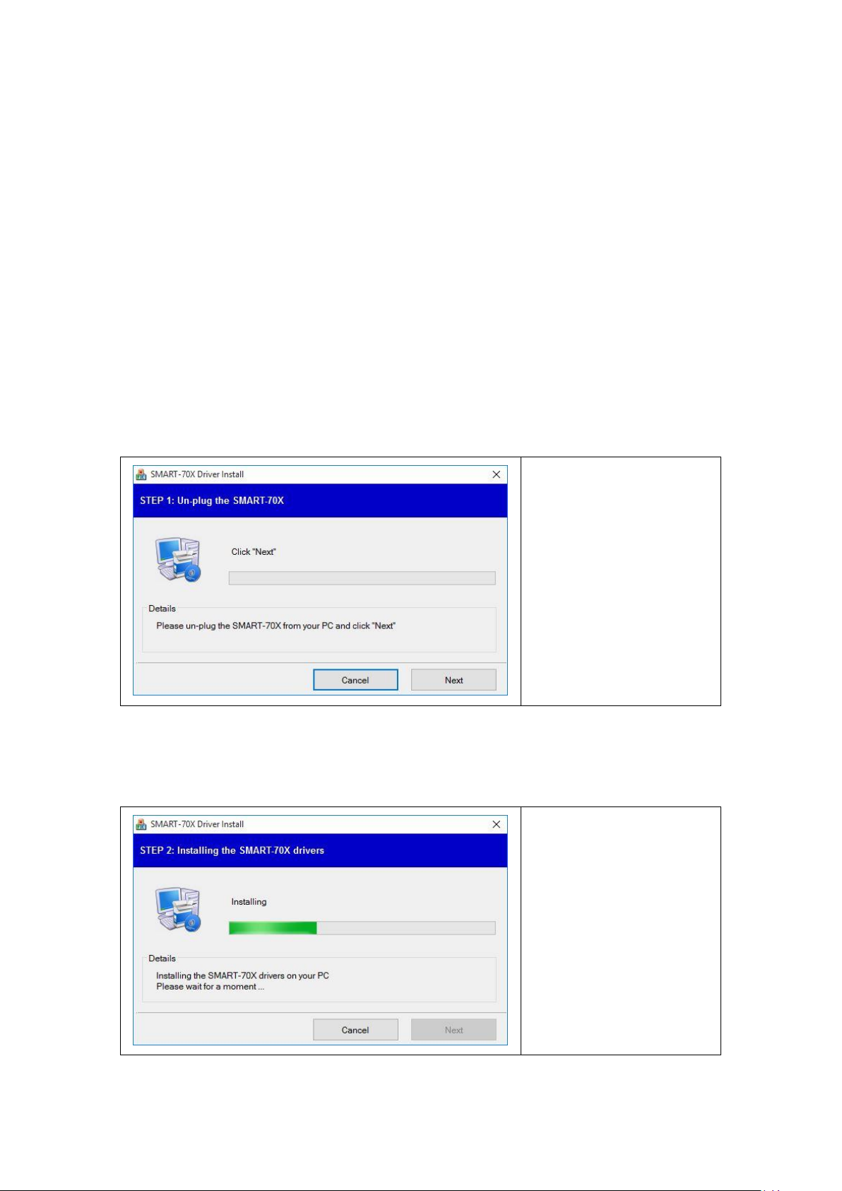
4.3. LaserCam
The left window is displayed
when running ‘Laser
Firmware’ after connecting
SMART-70X.
It works if ‘Microsoft
LifeCam Studio’ is shown in
the first list box.
Click ‘Search’ button after
checking a connection
status of SMART-70X if the
camera is not on the list.
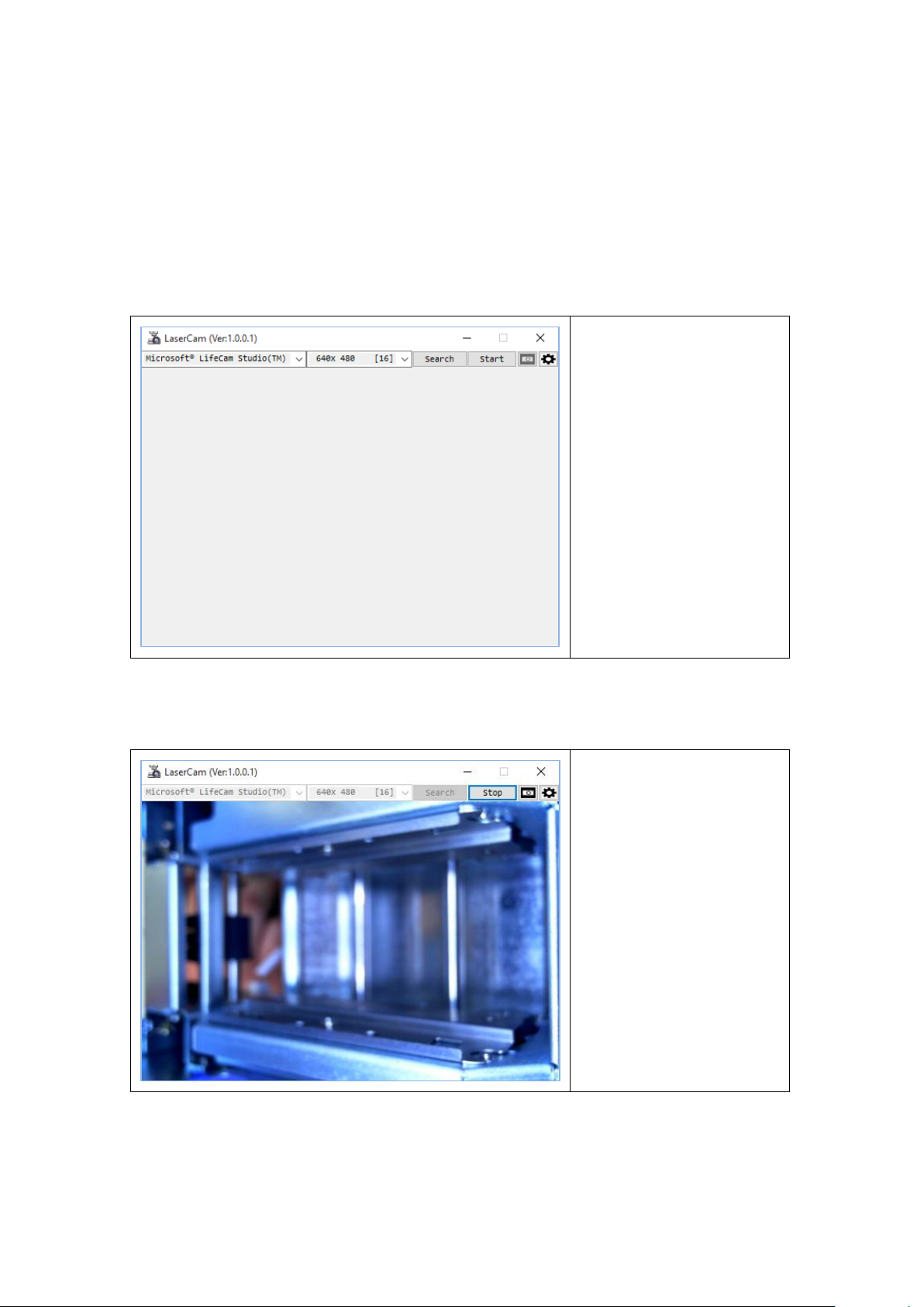
The inside of SMART-70X is
shown when clicking “Start”
button.
The image can be saved by
the resolution 640x480.
The size of image is
changed by dragging an
edge of window with
mouse.
The camera is installed by default in the SMART-70X and the status of engraving on real
time. Run ‘LaserCam’ in the ‘\SMART-70X\Utilities\’ folder.
1) Run LaserCam
2) Start LaserCam
25
Page 26

3) Save an image of LaserCam
To save an image in the
window, click a Camera icon
in the LaserCam.
To adjust a focus and white
balance, click Gear icon in
the LaserCam.
Focus
Set the focus of camera by Focus.
When “Auto Focus” is checked, it sets automatically.
Adjust a slider to show the image of printed card clear when
it set manually.
White Balance
Set the white balance of camera by White Balance.
When “Auto White Balance” is checked, it sets automatically.
Adjust a slider to show the image of printed card a feeling
of color as user wants when it set manually.
4) Configuration of LaserCam
26
Page 27

4.4. LaserTest
The left window is displayed
when running ‘LaserTest’
after connectina SMART70X.
The power of SMART-
70X should be connected
and turned on before
running LaserTest.
The SmartID or other
laser utility program
should be closed before
running LaserTest.
The ‘Connection failed to
SMART-70X’ pop-up
window is displayed if
LaserConfig can’t
connect the SMART-70X.
Connect
/
Disconnect
Connect/Disconnect button can connect/disconnect the
SMART-70X.
SMART-70X is disconnected if the ‘Disconnect’ button is
clicked on ‘Connect’ status.
SMART-70X is connected if the ‘Connect’ button is clicked
on ‘Disconnect’ status.
LaserTest is a sample program for encoding, printing and engraving by SMART-70X. The
basic functions of SMART-70X can be tested by LaserTest. Users can use SmartID or the
customized program by SDK.
Please run ‘LaserTest’ in the ‘\SMART-70X\Utilities\’ folder.
27
Page 28

Issue
Issue makes encoding, printing and engraving
automatically.
Check the operation as you want, enter the data and click
‘Run’ button.
For encoding, the proper encoder options should be
installed in the SMART-70X.
For MS encoding, check a proper coercivity of encoded card,
enter the data to encode.
For Contact/Contactless smart card encoding, enter the
APDU which a card can recognize.
Position of contact/contactless smart card should be
adjusted to the encoding position.
For Printing and Engraving, select a CSD file to design in
SmartID.
When checking ‘Error card handling’, the error card is moved
to ‘Error card drawer’ when encoding is failed.
Motion
Motion makes doing each operation of SMART-70X step
by step.
Input: input a card from left / right.
Move: move a card to the indicated position.
Flip: flip a card or rotate a card by the indicated angle.
Output: Eject a card to left / right.
Status
Status shows a status of sensors in SMART-70X.
Message
Message shows a operation of SMART-70X on real time.
28
Page 29

5. Specification
Model
SMART-70X
Laser Engraving
Laser Type
6W Air-Cooled DPSS Laser, ND:YAG
Resolution
1200dpi
Scanning
Raster & Vector Scanning
Engraving Mode
Single or Dual-sided Laser Engraving
Speed
103 cards/hour (Single-sided Laser engraving only)
CLI (Changeable Laser Image)
Yes
Warranty
20,000 hours
Card
Card Feeding
Automatic, Manual
Card Size
ISO CR80 (54mm x 86mm / 2.12” x 3.38”)
Card Thickness
0.76mm (30mil)
Card Type
Laserable PVC, PC (Polycorbonate) Card
Capacity
Input Hopper
Max. 500 Cards (Optional : SMART-70 Input Hopper)
Output Hopper
Max. 500 Cards (Optional : SMART-70 Output Hopper)
Error Card Bin
Max. 20 Cards
System
Display
LCD & LED
Control Panel
4 Buttons
Vision Camera
Laser Engraving Monitoring
Supported Platforms
Microsoft Windows 7/ 8/ 10
Communication
USB
Power Supply
100-240V~50/60Hz 2.5A
Temp. / Humidity
10~30℃ / 20~80%
Security
Physical Lock
Laser System, Error Card Bin
Options
Magnetic
ISO 7811 (Track I, II, III Read/ Write, HiCo/ LoCo)
Contact
ISO 7816 (ID-1)
Contactless
MIFARE, ISO 14443 (Type A/ B), ISO 15693, DESFIRE, iCLASS
Air Cleaning
Gas & Vapor Protection - Organic Vapor/Acid
Gas/Ammonia/Methylamine/Formaldehyde
Dimensions
Millimeter (WxLxH)
450 x 230 x 425
Inch (WxLxH)
17.7 x 9.1 x 16.7
Weight
Kg / Lbs
Approx. 25kg / 55 lbs
Laser Safety
IEC-60825-1 CLASS 1 Standard
Specifications and availability may change without notice.
29
 Loading...