

Page 1
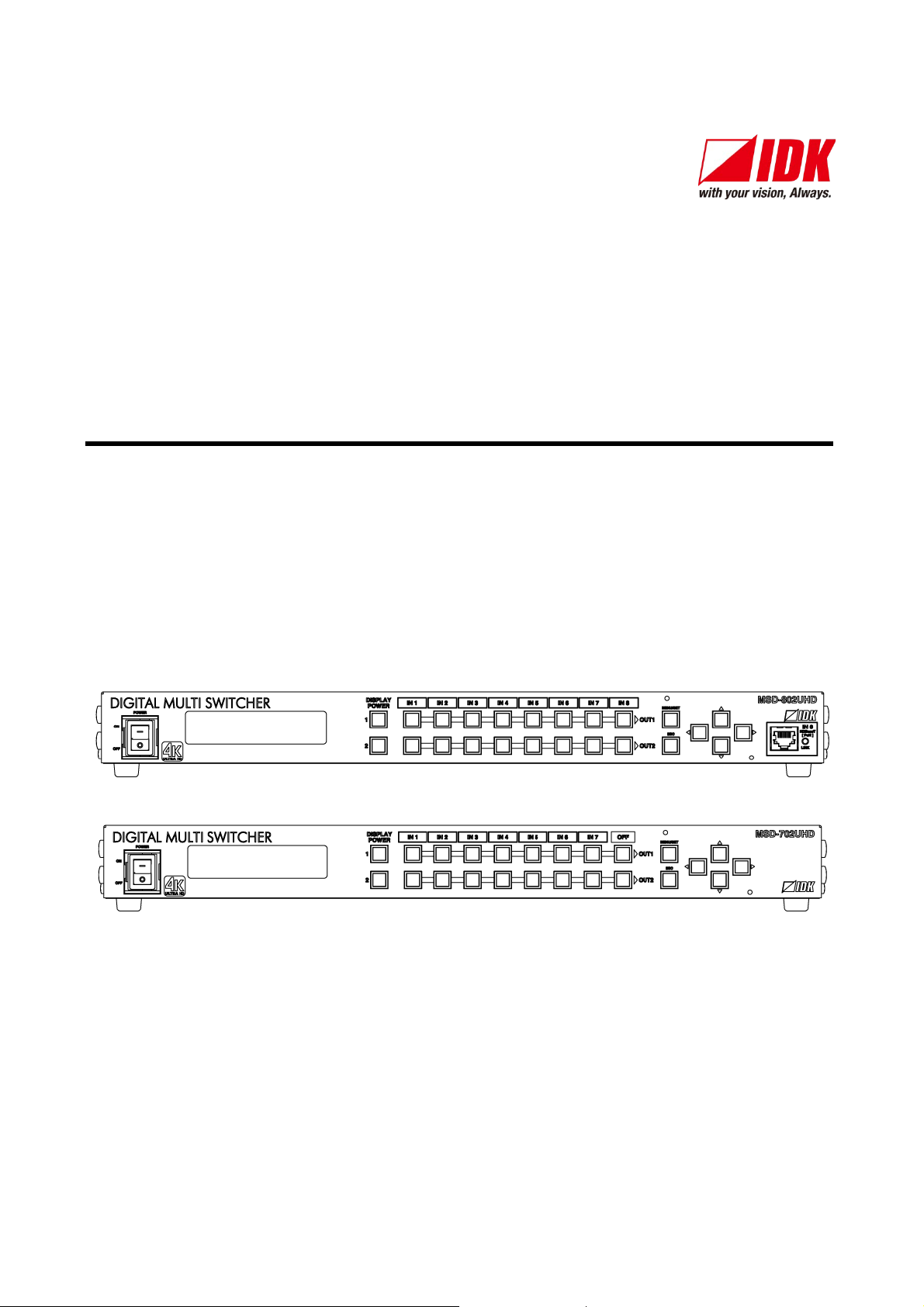
4K@60 and HDCP 2.2 supported Digital Multi Switcher
MSD-701UHD / 702UHD
MSD-801UHD / 802UHD
<User’s Guide>
Ver.1.1.0
Thank you for choosing our product.
To ensure the best performanc e of this product, please read this User’s Guide fully and carefully
before using it and keep t his manual together with the product for r eference as needed.
IDK Corporation
Page 2

MSD-701UHD / 702UHD / 801UHD/ 802UHD User’s Guide
Trademarks
Blu-ray Disc and Blu-ray are trademark s of Bl u-r ay Di sc Association.
ETHERNET is a registered trademark of Fuji Xerox Co., Lt d.
Google Chrome is a registered trademark or trademark of Google Inc.
HDBaseT™ and the HDBaseT Alliance Logo are trademarks of the HDBaseT Alliance.
The terms HDMI and HDMI High-Definition M ultimedia Interface, and the HDMI Logo ar e trademarks or
registered tradem ar k s of HDM I Licensi ng A dm inistrator, Inc. in the United S tates and other countries.
Javascript
companies in t he United States and other countries.
Microsoft, Windows, Internet Explorer are either registered trademarks or tradem ar k s of the Mic r osoft
Corporation in the United States and other countri es.
The terms Mozilla and Firefox, and their logos are registered trademarks or trademark s of Mozilla
Foundation in the United States and other count ri es.
Oracle and Java are trademarks of Oracle Corporation its subsidiar ies, and affili ated com panies in the
United States and other c ountries.
PJLink is a trademark in Japan, the United St ates, and ot her c ountries/regi ons.
The terms Anti-snow and Connection Reset are registered trademarks of IDK Corporation in Japan.
All other company and product names menti oned in this manual are either register ed trademarks or
trademark s of their r espect ive owners. In this manual, the “®” or “™” marks may not be specified.
®
is a tradenark or r egister ed trademark of Oracle Corporation, its subsidiari es, and aff iliated
2
Page 3

MSD-701UHD / 702UHD / 801UHD/ 802UHD User’s Guide
Before reading this manual
All rights reserv ed.
Some of the contents i n this User’s G uide such as appearance diagr ams, menu operations,
communication commands, and so on may differ depending on the v er si on of the pr oduc t.
This User’s Guide is subject to change wit hout notice. You can download the lat est v er si on from IDK’s
website at: http://www.idkav.com
The reference manual consists of the following two volumes:
■ User’s guide (this document):
Provides explanations and procedures for operat ions, installation, c onnec tions among devices, I/O
adjustment and settings.
■ Command guide: Please download the c om mand guide from the website above.
Provides explanations and procedures for ext er nal c ontrol using RS-232C and LAN communications.
FCC STAT EMENT
This equipment has been tested and found to comply with the limits for a Class A digital device, pursuant to
part 15 of the FCC Rules. These limit s are designed to provide reasonable pr otection against harmful
interfer enc e when the equipment is operated in a commercial environment. This equipment generates, uses,
and can radiate radio frequenc y ener gy and, if not install ed and used in accor danc e with the instruction
manual, may cause harmful interference to radio communications. Operation of this equipment in a residential
area is likely to cause harmful interference, i n which case the user will be required to correct the interference
at his own expense.
CE MARKING
This equipment complies with the essential requi r em ents of t he r elev ant European health, safet y and
environmental protection legislation.
WEEE MARKING
Waste Electrical and Elect r onic Equipment (WEEE), Directive 2002/96/EC
(This directive is only valid in the EU.)
This equipment complies with the W EEE Dir ectiv e (2002/96/EC) marking requirement.
The left marking indicates that y ou m ust not discard this electrical/elec tronic equipment in
domestic household waste.
3
Page 4
MSD-701UHD / 702UHD / 801UHD/ 802UHD User’s Guide
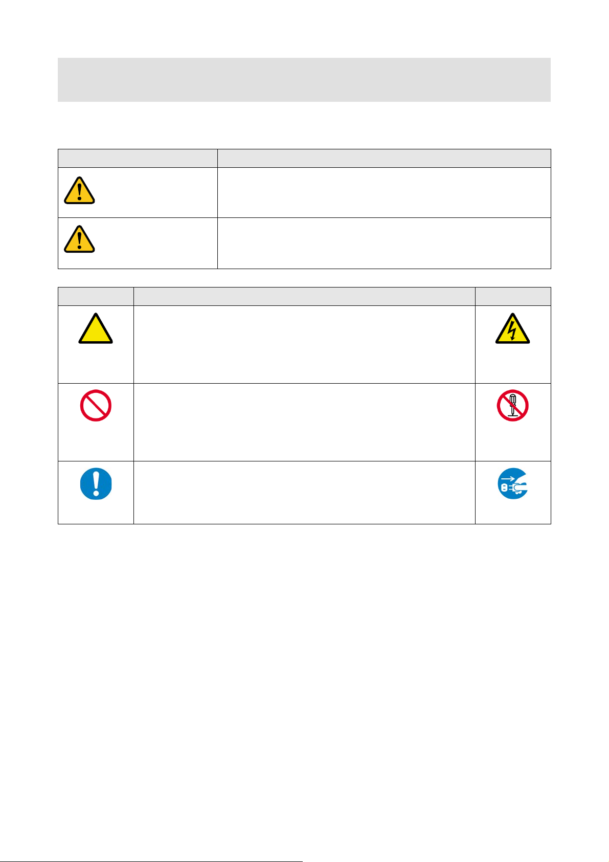
Enforcement Symbol
Description
Indicates the pr esence of a haz ar d that m ay result in death or serious
Indicates the pr esence of a haz ar d that m ay cause mi nor personal
Symbol
Description
Example
disassemble
Caution
Warning
Safety Instructions
Read and understand all safety and operating instruc tions before using this product. Follow all instructions
and cautions as detailed in this document.
Caution
Prohibited
Instruction
personal injur y if the warning is ignored or the product is handled
incorrectly.
This symbol is intended to alert the user. (Warning and caution)
This symbol is intended to pr ohibit the user from specified actions.
This symbol is intended to instr uc t the user.
injury or property damage if the caution is ignored or the product is
handled incorr ec tly.
Electrical
Hazard
Do not
Unplug
4
Page 5
Do not place the product in any unstabl e place.
Install the product in a hori z ontal and stable place. Ot h erwise, it m ay fall/turn over and lead to inj ury.
Do not place the product in any environment with vibration.
Otherw ise, it may mo ve/fall and l ead to injury.
Keep out any foreign objects.
from the vent holes.
For power cable/ plug :
contact your IDK representative.
disassemble
Do not repair, modify or disassemble.
touch
In the event of electrical storms, keep away from the main unit and cabl es such as
For insta lla t i on:
IDK. Improper installation may lead to the risk of fire, electric shock, injury, or property damage.
Set the power plug in a conv enient pla ce to unpl ug easily .
situation or for e as y dis connect i on during ext en d ed periods of n on -use.
Insert the power plug into an appropriate outlet completely.
or fire. Do not use a d am ag ed plug or con n ect to a damaged outlet.
Clean the power plug regul arly.
If the plug is covered in dust, it may i n crease t he risk of firer.
Unplug immediately if the product smokes, makes unusual noi se, o r produces a
the product stops smoking, contact your IDK representative.
Unplug immediately if the product falls and/or if the cabinet is damaged.
maintenance and repair, contact your IDK representative.
Unplug immediately if water or other objects are directed inside.
maintenance and repair, contact your IDK representative.
For connection
Differences in ground p oten tial among prod uc t pop ulati on of int er conn ect ed produc ts and ot her external devic es
Power may be restored after all signal/control cables are connected to each d evice.
Warning
Prohibited
MSD-701UHD / 702UHD / 801UHD/ 802UHD User’s Guide
In order to av oi d fire or electr ic s h ock , d o n ot all ow f or eig n ob j ects, suc h as m et al and pap er , t o enter the pr oduc t
• Do not scratch, heat, or modify, including lengthening them.
• Do not pull, place heavy objects on them, or pinch them.
• Do not bend, twist, or tie them together forcefully.
Misuse of th e pow er c able and plug may cause fire or electric shock. If power cables/plugs become damaged,
Do not
Do not
Instruction
Unplug
Since the product includes circuitry that uses potentially lethal, high voltage levels, disassembly by unauthorized
personnel may lead to the risk of fire or electric shock. For internal inspection or repair, contact your IDK
representative.
power cable and LAN cable.
Contact may cause electric shock
The product is intended to be installed by skilled technicians. For installation, please contact a system integrator or
Unobstr uc t ed ac cess to the plug enables unplugging t h e product in case of any extr aor d in ary failur e, abnormal
If the plug is partially inserted, arching may cause the connection to overheat, increasing the risk of electrical shock
burning odor.
If you continue to use the product under these conditions, it may cause electric shock or fi re. After confirming that
If you continue to use the product under these conditions, it may increase the risk of electrical shock or fire. For
If you continue to use the product under these conditions, it may increase the risk of electrical shock or fire. For
may increase the risk of electric shock t o personn el or cause damage to the devices or cabling infrastructure. When
using cables to connect devices, including connection of long-distance transmission cables, unpl ug th e power
Instruction
cables of all interconnected devices.
5
Page 6
MSD-701UHD / 702UHD / 801UHD/ 802UHD User’s Guide
Instruction
Mount the product in a t he rack m eeting EIA standards, and maint ain spaces above and
Never insert screws without the r ubber feet into the threaded holes on the bot tom of the
Reinstall the ori ginally supplied rubber feet using only the originally supplied screws.
Instruction
Do not place the product at elevations of 2,000 meters (6562 feet) or higher above sea
Do not place the product in any place where i t will be subjected to high
product’s performance and reliability and may increase the risk of fire.
Do not place the product in humid, oil smoke filled, or dusty place.
Do not block the vent holes.
may incr ease the risk of fire.
Do not place or stack heavy objects on the pro duc t.
risk of pers on al in jury.
Do not exceed ratings of outlet and wiring devices.
Use only the supplied AC adapter and power cable.
use the supplied AC power connection cable for this product.
No wet hands
Do not plug or unplug with wet hands.
Use and store the product within the specified temperature/humidity range.
risk of fire or electric shock.
Turn off devices while making connections to another device.
If the product won’t be used for an extend ed period of ti me, unplug it.
Unplug the product before cleaning.
For insta lla t i on
Caution
Prohibited
Instruction
temperatures.
If the product is subjected to direct sunlight or high temperatures while under operation, it may affect the
If the product is placed near humidifiers or i n a d us t y ar ea, it m ay increase the risk of fire or e lec t ri c shock.
If ventilation slots are blocked, it may cause the prod uc t t o ov er heat, aff ecting perf or m ance and reli ability an d
Failure to observe this precaution may result in damage to the product and other property and may lead to the
Exceed in g the rating of an out l et m ay inc rease t h e risk of f ir e an d electric sh ock .
Do not use the supplied AC adapter and power cable with other products.
If non-compliant adapter or power cables are used, i t m ay increase the risk of fire or elec t rical shoc k. Always
Failure to observe this precaution may increase the ris k of electrical shock.
If the product is used outside the specified range for temperature and humidity continuously, it may increase the
Failure t o observe this precaut i on m ay inc r ease the ris k of fire or elec tr ic sh oc k.
Failure t o observe this precaut i on m ay inc r ease the ris k of fire.
Unplug
To prevent electric shock.
For rack mount devices:
below for air circulation. For your safety, attach an L-shaped bracket in addition to the
panel mount brac k et kit t o improve mechanical stability.
For devices with rubber feet:
product. Doing so may lead to damage when the screws contact electrical circuitr y or
Instruction
components insi de the product.
Altitude:
level. Failur e to do so may shorten the life of the internal parts and result in malfunctions.
6
Page 7

MSD-701UHD / 702UHD / 801UHD/ 802UHD User’s Guide
Table of Contents
1 About this Guide ..................................................................................................................................11
2 Included Items .....................................................................................................................................12
3 Product outline ....................................................................................................................................13
4 Features ..............................................................................................................................................14
5 Panels .................................................................................................................................................15
5.1 Front panel .....................................................................................................................................15
5.2 Rear panel......................................................................................................................................16
6 System configurat ion example .............................................................................................................18
7 Precautions .........................................................................................................................................19
7.1 Installation ......................................................................................................................................19
7.2 Cabling ...........................................................................................................................................20
7.2.1 Cables ....................................................................................................................................21
7.2.2 DVI-I input connector ...............................................................................................................21
7.2.3 Twisted pair cable for extension ..............................................................................................23
7.2.4 Connecting audi o c ables .........................................................................................................24
7.2.5 Connecting RS-232C cable .....................................................................................................24
7.2.6 Contact closure .......................................................................................................................25
7.2.7 Command control ....................................................................................................................25
8 Basic operati on....................................................................................................................................26
8.1 Power up init period ........................................................................................................................26
8.2 Switching input channel ..................................................................................................................26
8.2.1 Selecting input channels..........................................................................................................26
8.2.2 Turning off input si gnal ............................................................................................................27
8.3 Menu operation ..............................................................................................................................28
8.4 Menu operation ..............................................................................................................................29
8.5 Locking and unl oc ki ng k ey s ............................................................................................................29
8.6 Initialization ....................................................................................................................................30
8.7 Web menu operation ......................................................................................................................41
8.7.1 Control from WEB browser ......................................................................................................41
8.7.2 How to use WEB menu ...........................................................................................................42
9 Menu ...................................................................................................................................................43
9.1 Menu list .........................................................................................................................................43
9.2 Input Signal Autom atic Detection ....................................................................................................45
9.3 Channel switching mode .................................................................................................................46
9.4 Setting posit ion, size, and masking .................................................................................................47
9.4.1 Output resolution .....................................................................................................................47
9.4.2 Aspect ratio for si nk device ......................................................................................................49
9.4.3 Aspect ratio .............................................................................................................................49
9.4.4 Aspect ratio control .................................................................................................................50
9.4.5 Overscan ................................................................................................................................50
9.4.6 Display position .......................................................................................................................50
9.4.7 Display size .............................................................................................................................51
9.4.8 Masking ..................................................................................................................................52
9.4.9 Automatic sizi ng ......................................................................................................................52
9.4.10 Background color ....................................................................................................................53
9.4.11 Test pattern .............................................................................................................................53
9.5 Quality settings ...............................................................................................................................54
7
Page 8

MSD-701UHD / 702UHD / 801UHD/ 802UHD User’s Guide
Sharpness ...............................................................................................................................54
9.5.1
9.5.2 Brightness ...............................................................................................................................54
9.5.3 Contrast ..................................................................................................................................54
9.5.4 HUE ........................................................................................................................................55
9.5.5 Saturation ...............................................................................................................................55
9.5.6 Black level ...............................................................................................................................55
9.5.7 Gamma ...................................................................................................................................55
9.5.8 Default color ............................................................................................................................56
9.6 Input settings ..................................................................................................................................57
9.6.1 No-signal input monitoring .......................................................................................................57
9.6.2 Input HDCP setting .................................................................................................................58
9.6.3 Analog input signal parameters ...............................................................................................59
9.6.4 Automatic detection of video input interruption .........................................................................60
9.6.5 Selecting signal of DVI input connector....................................................................................60
9.6.6 HDBaseT input long reach mode .............................................................................................60
9.6.7 Fixing settings for eac h input signal .........................................................................................61
9.7 Setting i nput timing .........................................................................................................................62
9.7.1 Automatic measurement..........................................................................................................63
9.7.2 The total number of horiz ontal dots..........................................................................................65
9.7.3 Start positi on ...........................................................................................................................65
9.7.4 Active area ..............................................................................................................................66
9.7.5 Automatic measurement of start position .................................................................................67
9.7.6 Automatic setti ng of input timing ..............................................................................................67
9.7.7 Loading device data ................................................................................................................68
9.7.8 Registering device data ...........................................................................................................68
9.7.9 Tracking ..................................................................................................................................68
9.8 Output settings ...............................................................................................................................69
9.8.1 Output mode ...........................................................................................................................69
9.8.2 Synchronous signal output with no input video.........................................................................69
9.8.3 Output video wit h no input video ..............................................................................................70
9.8.4 Window transacti on effect .......................................................................................................70
9.8.5 Window transacti on speed ......................................................................................................70
9.8.6 Wipe color ...............................................................................................................................70
9.8.7 Video output connector............................................................................................................71
9.8.8 HDCP .....................................................................................................................................71
9.8.9 The number of HDCP retries ...................................................................................................72
9.8.10 Deep Color ..............................................................................................................................72
9.8.11 CEC connection ......................................................................................................................73
9.8.12 HDCP re-authentication...........................................................................................................73
9.8.13 Priority of input channel automatic switchi ng ............................................................................74
9.8.14 Masking time after automatic switching of input channel ..........................................................76
9.8.15 Channel switching mode of automatic switching ......................................................................76
9.8.16 HDBaseT output long r eac h m ode ...........................................................................................76
9.9 Audio setting ..................................................................................................................................77
9.9.1 Output level .............................................................................................................................78
9.9.2 Output mu te ............................................................................................................................78
9.9.3 Input selection .........................................................................................................................78
9.9.4 Input level ...............................................................................................................................78
9.9.5 Lip sync ..................................................................................................................................79
9.9.6 Sampling frequency.................................................................................................................79
8
Page 9

MSD-701UHD / 702UHD / 801UHD/ 802UHD User’s Guide
Audio output connector............................................................................................................80
9.9.7
9.9.8 Digital audio output connector .................................................................................................80
9.9.9 Multi channel audio output .......................................................................................................80
9.9.10 Multi channel audio output priority ...........................................................................................81
9.9.11 Test tone .................................................................................................................................82
9.10 EDID (Ext ended Display Identification Data) ...................................................................................83
9.10.1 EDID .......................................................................................................................................83
9.10.2 Resolution for PCs ..................................................................................................................84
9.10.3 Input resolution for AV devices ................................................................................................86
9.10.4 Deep Color ..............................................................................................................................87
9.10.5 Audio format............................................................................................................................87
9.10.6 Speaker confi gur ation .............................................................................................................88
9.10.7 Copying EDID .........................................................................................................................89
9.11 RS-232C ........................................................................................................................................90
9.11.1 RS-232C communication setting .............................................................................................90
9.11.2 RS-232C operation mode ........................................................................................................91
9.11.3 RS-232C HDBaseT connecti on ...............................................................................................91
9.12 LAN ................................................................................................................................................92
9.12.1 IP address/Subnet m ask/ Gateway address .............................................................................94
9.12.2 LAN operation mode ...............................................................................................................94
9.12.3 TCP port number.....................................................................................................................95
9.12.4 MAC address ..........................................................................................................................95
9.13 Setti ng c ontrol command ................................................................................................................96
9.13.1 Registering/editing control command .......................................................................................98
9.13.2 Registering / Editi ng r eply command .....................................................................................103
9.13.3 Command link .......................................................................................................................106
9.13.4 Command executi on .............................................................................................................107
9.13.5 Invalid durati on at control command executi on ......................................................................107
9.13.6 Initializing registered commands and link ...............................................................................107
9.13.7 Command execution key: Illuminating condition .....................................................................108
9.13.8 Blinking at command exec ution key .......................................................................................108
9.14 Preset memory .............................................................................................................................109
9.14.1 Recalling cross point .............................................................................................................109
9.14.2 Saving cross point .................................................................................................................109
9.14.3 Editing cross point .................................................................................................................110
9.14.4 Recalling all sett ings..............................................................................................................110
9.14.5 Saving all settings .................................................................................................................111
9.14.6 Copying output setting ...........................................................................................................112
9.14.7 Startup setting .......................................................................................................................113
9.15 Bitmap setting...............................................................................................................................114
9.15.1 Sending bitmap file ................................................................................................................114
9.15.2 Outputting bitmap image .......................................................................................................116
9.15.3 Background color ..................................................................................................................116
9.15.4 Aspect ratio ...........................................................................................................................116
9.15.5 Display position .....................................................................................................................117
9.15.6 Assigning input c hannel.........................................................................................................117
9.15.7 Startup bitm ap output ............................................................................................................117
9.15.8 Dividing memory area ...........................................................................................................118
9.15.9 Input image capture...............................................................................................................120
9.16 Startup setting ..............................................................................................................................122
9
Page 10

MSD-701UHD / 702UHD / 801UHD/ 802UHD User’s Guide
DISPLAY PO WER keys ........................................................................................................122
9.16.1
9.16.2 Key function lock ...................................................................................................................123
9.17 Other settings ...............................................................................................................................124
9.17.1 Grouping key function lock ....................................................................................................124
9.17.2 Buzzer ..................................................................................................................................125
9.17.3 Power saving ........................................................................................................................125
9.17.4 DISPLAY POWER key press ing time ....................................................................................125
9.17.5 HDBaseT input power supply ................................................................................................125
9.17.6 Top page...............................................................................................................................126
9.17.7 Input signal status .................................................................................................................127
9.17.8 Sink device stat us .................................................................................................................129
9.17.9 Viewing sink device E DID ......................................................................................................131
9.17.10 Viewing version information ...................................................................................................132
10 Product specificati on .........................................................................................................................133
11 Troubleshooting.................................................................................................................................141
10
Page 11
MSD-701UHD / 702UHD / 801UHD/ 802UHD User’s Guide
Number of I/Os
1 About this Guide
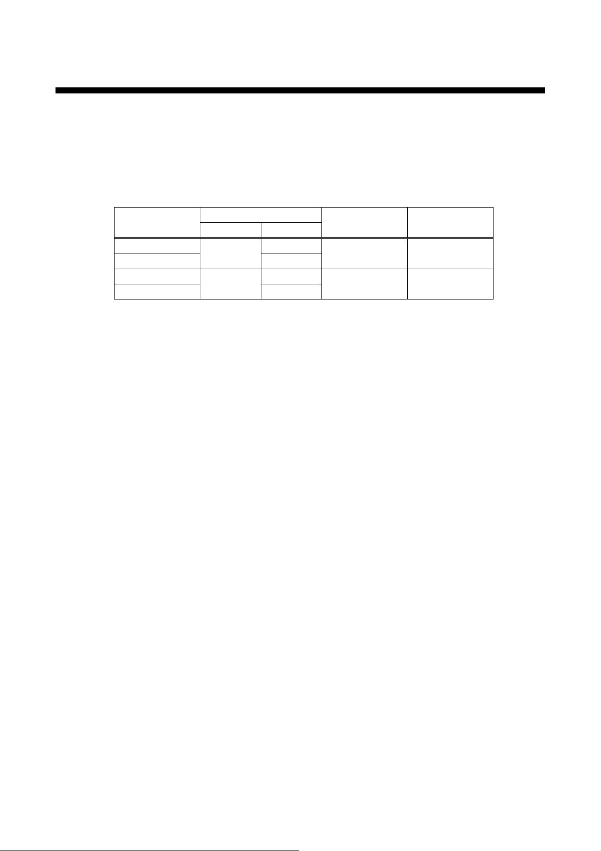
This user’s guide expl ains how to use the MSD-701UHD / 702UHD / 801UHD / 802UHD digital multi switcher
(hereaft er ref er r ed to as “MSD” ), whic h hav e a scan conv er ter. The MSD series is divided into four models as
shown in the table below.
Since descriptions in this document are for MSD-802UHD, there may be slight differences between the model
and other models.
[Table 1.1] Main differences among MSD-701UHD / 702UHD / 801UHD / 802UHD
Model
MSD-701UHD 7 1 No Yes
MSD-702UHD 2
MSD-801UHD 8 1 Yes No
MSD-802UHD 2
Input Output
Front panel
HDBaseT input
【See: 8.2.2 Turning off input signal】
Front panel OFF
Keys
11
Page 12
MSD-701UHD / 702UHD / 801UHD/ 802UHD User’s Guide
2 Included It e ms
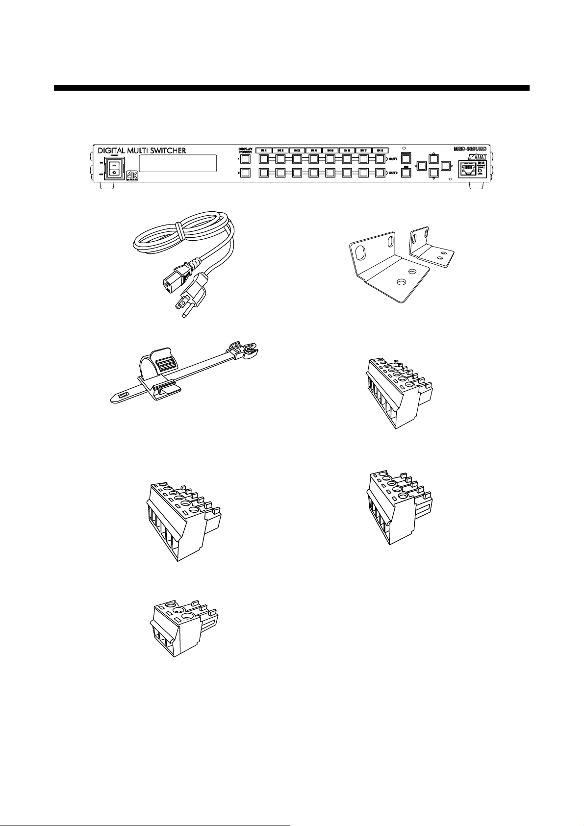
Ensure all items below are included in the package.
If any items are missing or dam aged, please contact IDK.
One (1) main unit (MSD-802UHD)
One (1) power cord (5.91 ft. (1.8 m))
Two (2) rack mounting brac k ets
Cable clamps
Six (6) for MSD-801UHD / MSD-701UHD
Seven (7) for MSD-802UHD / MSD-702UHD
One (1) 6-pin terminal blocks
One (1) 3-pin terminal blocks
[Fig. 2.1] Inc luded ite m s list
One (1) 7-pin terminal blocks
5-pin terminal blocks
Four (4) for MSD-801UHD / MSD-701UHD
Five (5) for MSD-802UHD / MSD-702UHD
12
Page 13
MSD-701UHD / 702UHD / 801UHD/ 802UHD User’s Guide
Video
matrix
switch
Scan
converter
Audio
matrix
switch
Digital video/audio
HDMI DVI
Inputs
2
Analog audio
L/R balanced/unbalanced
EDID emu lator
A/D conversion
IN1 to IN2
Analog audio
L/R balanced/unbalanced
MSD-802UHD
Digital video/audio
HDMI DVI
Up to 98 ft . (30 m)
*1
Up to 98 ft . (30 m)
*1
D/A conversion
IN1 to IN3
Lipsync
2
Outputs
Digital video/audio
HDMI DVI
Analog video
Composite
Y/C
RGB
YPbPr
EDID emu lator
IN6 to IN7
Digital
A/D conversion
Analog
Up to 98 ft . (30 m)
*1
Inputs
2
2
Outputs
3
Inputs
Digital video /audio/
communication for extension
HDBaseT
Outputs
2
Up to 328 ft. (100 m)
*2
Digital video/audio
HDMI DVI
Inputs
3
EDID emu lator
IN3 to IN5
Up to 98 ft . (30 m)
*1
Digital video /audio/
communication for extension
HDBaseT
Input
1
IN8
Up to 328 ft. (100 m)
*2
2
chs
2
chs
Receiver
EDID emu lator
Transmitter
PoH
RS-232C
LAN
1
Port
1
Port
CPU
Switch
HUB
*1
Maximum extension distance
Up to 98 ft. (30 m) : 1080p@60
Up to 39 ft. (12 m) : 4K@60 (when 18 Gbps high-speed cable is used) (IN1, IN2, OUT1 and OUT2 only)
*2
Maximum extension distance
Up to 328 ft. (100 m) : Input/4K@60 (4:2:0), Output/4K@30
Up to 492 ft. (150 m) :1080p (24 bit) in Long reach mode with IDK’s HDBaseT products support ing 328 ft. (100 m)
3 Product outline
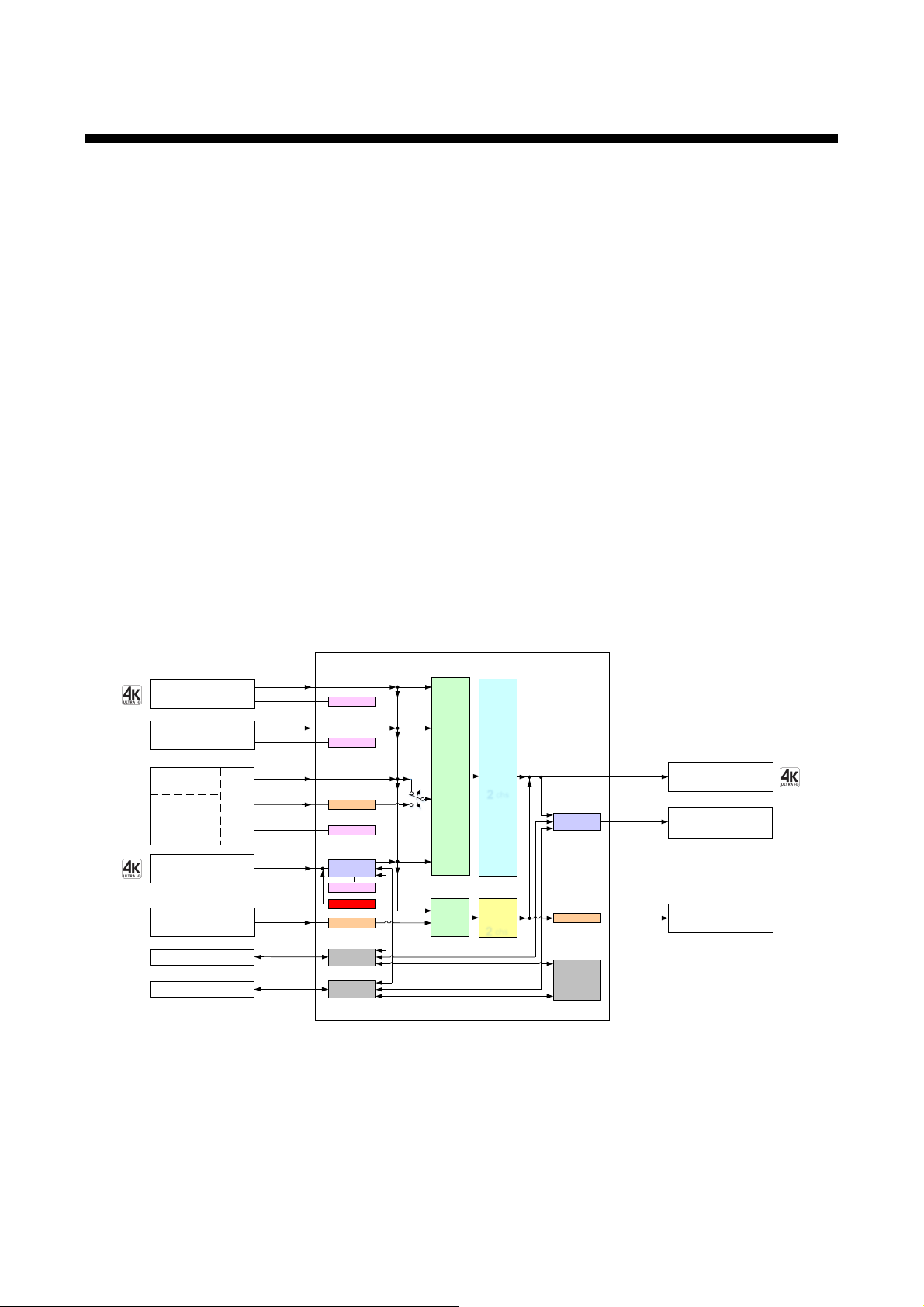
The MSD-701UHD / 702UHD / 801UHD / 802UHD are high-performance digital multi switchers with a built -in
scan converter.
The following input signal formats are supported: HDM I, DVI, composite video, S video, analog RGB, and
analog YPbPr signals. All input video signals are converted to HDMI signals and output at user definable
resolution f ormats up to 4K@60.
MSD-801UHD and MSD-802UHD include front panel HDBaseT i nput i n or der to prov ide power to the
transmitter that support PoH (Power over HDBaseT) .
For audio input and output, digital audio and analog audio formats are supported, and they are cross-routable.
Audio levels of each input and output can be set individually. The lip sync feature provides the user with a
means to control time alignment between the video and audio.
The MSD is controlled remotely via RS-232C or LAN. Additi onally, external devices connected to the MSD
can be controlled through RS-232C, LAN, CEC, or contact closure by registering external control commands.
The waiting function can delay the issuance of register ed commands to external devices. As an example, a
power down command can be delay ed until after sufficient lamp cooling tim e for a projector has elapsed.
Control commands for external devic es can be executed from front panel keys or in response to commands
via RS-232C or LAN. Commands can also be executed when input channel selec tion keys are operated or
the MSD is powered ON.
[Fig. 3.1] MSD-802UHD diagram
13
Page 14

MSD-701UHD / 702UHD / 801UHD/ 802UHD User’s Guide
■
■
■
■
■
4 Features
Video
・Up to 4K@60 (4:4:4)
・HDCP 1.4 / 2.2
・Up to 492 ft. (150 m) over Cat6 cable (Long reach mode)
・Motion adaptiv e I/P conv er si on
・Scan conversion (independent for each output )
・Aspect ratio contr ol
・Seamless switching
*2
・A/D conversion
・Anti-snow (automatic recovery from HDCP err or )
Audio
・A/D, D/A conversion
・Volume adjustment
・Lip sync
Control Input
・ RS-232C
・ LAN
・ Command control
Control output
・ Control command output (e.g. controlling projector)
・ PJLink
・ Power control of sink device over CEC
・ Contact closure
Others
・Power over HDBaseT (PoH) power feeding (HDBaseT input)
・EDID emulation
・All functions and configuration settings accessible through browser
・Automatic input detec tion and switching
・Audio breakaway enables independent audio and video switc hing
・Cross point memory
・Preset memory
・Last memory
・Connection Reset
・Security lock
*1
For Long reach mode, up to 1080p (24 bit) resolutions are supported.
*2
Seamless switching with a blac k fram e.
*3
Only for MSD-801UHD / 802UHD.
Tip:
For Long reach mode, use IDK’s HDBaseT products support ing 328 ft. (100 m).
*1
*3
14
Page 15
5 Panels
①
⑥
⑧
③ ④
②
⑤ ⑦
#
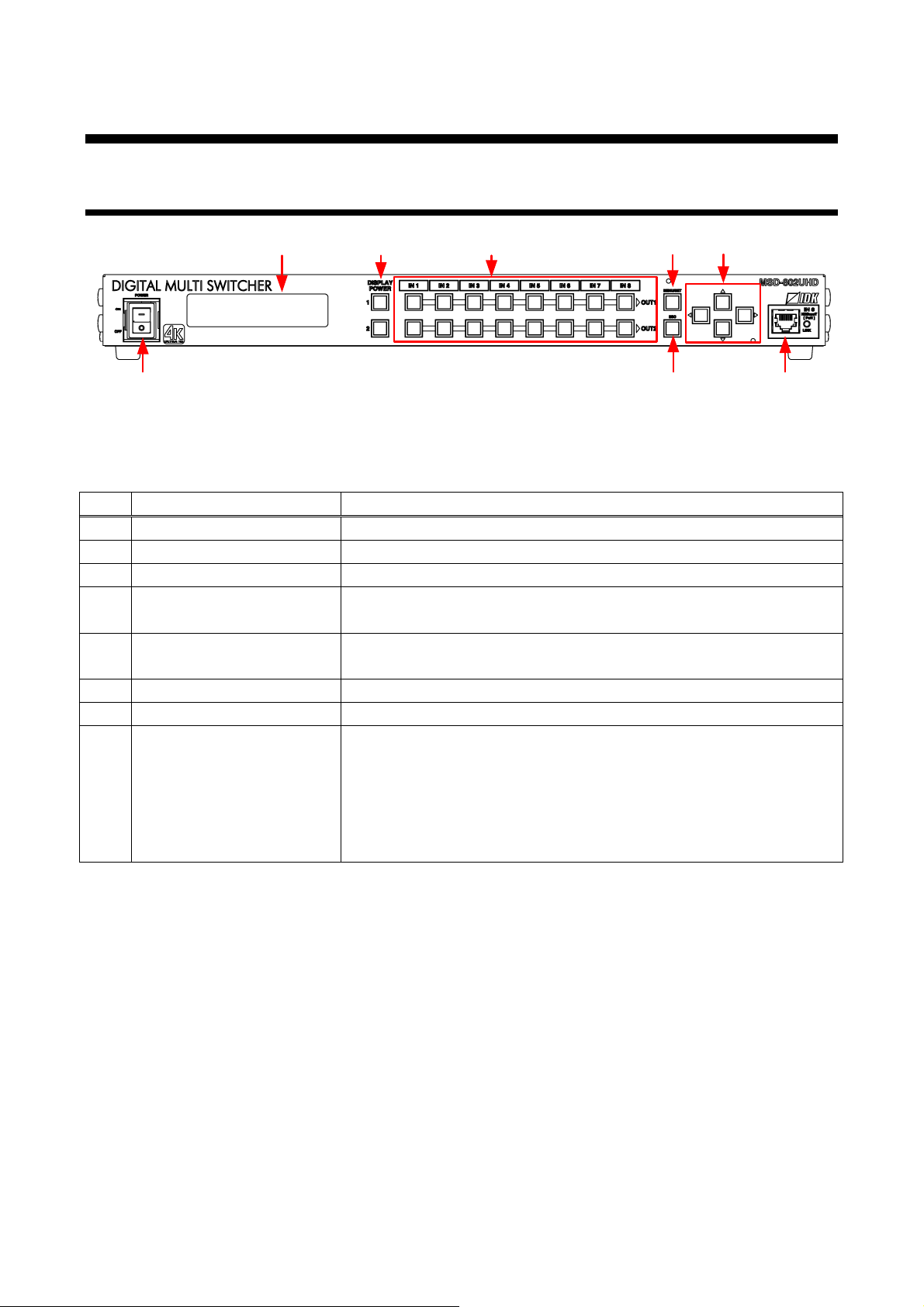
Name
Description
See: 8.2 Switching input channel】
MENU/SET key
Selects menus and edits / controls / stores settings.
See: 8.3 Menu operati on】
Arrow keys (▲, ▼, ◄, ►)
Switches menu, m ov es cursor, and c hanges setting values
HDBaseT input connec tor
Input connector for HDBaseT signal
5.1 Front panel
MSD-701UHD / 702UHD / 801UHD/ 802UHD User’s Guide
[Fig. 5.1] Fr ont panel drawing (MSD-802UHD)
[Table 5.1] Front panel’s name and description
① POWER switch Powers on / off the MSD.
② VFD screen Displays menus and settings.
③ DISPLAY POWER key Turns on / off connect ed sink devices.
④ Input channel sel ec tion key Selects input channels.
【
⑤
⑥ ESC key Ends the current menu setti ng
⑦
⑧
Connects to a transmitt er ov er a twisted pair cable.
Provides power to HDBaseT transmitter that supports PoH.
【See: 6 System configuration ex am ple】
【See: 7.2.3 Twisted pair cable for extension】
【See: 9.6.6 HDBaseT input long reach mode】
【
15
Page 16
MSD-701UHD / 702UHD / 801UHD/ 802UHD User’s Guide
⑩
⑪ ⑫
⑬
⑤④
③②①
⑥
⑦
⑨⑧
⑪
⑫ ⑬
⑭
such as Blu-ray players.
See: [Fig. 7.2] Attaching a cable clamp】
See: 7.2.2 DVI-I input connector】
See: 7.2.4 Connecting audio cables】
See: 7.2.7 Command cont r ol】
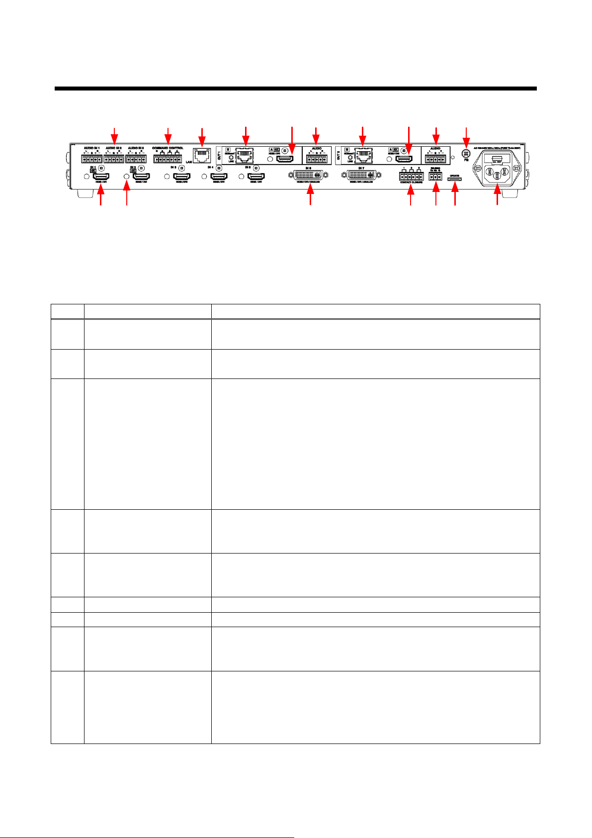
5.2 Rear panel
[Fig. 5.2] Rear panel drawing (MSD-802UHD)
[Table 5.2] Rear panel’s part name and description
# Name Description
HDMI input connector
①
Input connector s for HDMI and DVI si gnals to interface source devices,
HDMI cable fixing hole Retains HDMI cables by inserting cable clamps.
②
DVI input connector Input connectors for DVI-I and DVI-D cabl es.
③
Contact closure For external device control by dry contac t closure
④
RS-232C connector For external control by c ommunication commands
⑤
Maintenance connec tor Factory use only.
⑥
AC power inlet For use with provi ded power cable
⑦
Audio input connector Input connector for analog audio signals
⑧
COMMAND CONTROL
⑨
connector
【
HDMI signal can be interfaced using an HDMI-DVI conversion c able.
Analog video also can be input usi ng a DVI-analog conversion cable.
・HDMI
・Analog RGB (such as PC)
・Analog YPbPr (SDTV / HDTV)
・Cpmposite video (NTSC / PAL)
・S video (NTSC / PAL)
【
Connector type: Terminal block (6-pin).
【See: 7.2.6 Contact closure】
Connector type: Termi nal block (3-pin).
【See: 7.2.5 Connecting RS-232C cable】
Connector type: Termi nal block (5-pin)
【
For external interface that execute commands from a switch box
The connected switch box operates as control comm and ex ec ution keys
(COMMAND A to COMMAND C).
Connector type: Terminal block (7-pin)
【
16
Page 17
MSD-701UHD / 702UHD / 801UHD/ 802UHD User’s Guide
See: 9.8.16 HDBaseT output long reach mode】
such as LC monitors and proj ector s
[Table 5.3] Rear panel’s part name and description (Cont’d)
# Name Description
LAN connector For external control by c ommunication commands or web browsers
⑩
HDBaseT output
⑪
connector
HDMI output connect or
⑫
Audio output connector Analog audio output connectors interface to amplifiers, speakers, and
⑬
Frame ground Use for bonding chassis to local ground. An M4 screw is used.
⑭
Output connector for HDBaseT signal
Connects to a receiv er over a twisted pair cable.
【See: 7.2.3 Twisted pair cable for extension】
【
Output connector for HDMI and DVI signal interfaces with sink dev ic es
mixers.
Connector type: Termi nal block (5-pin)
【See: 7.2.4 Connecting audio cables】
17
Page 18
MSD-701UHD / 702UHD / 801UHD/ 802UHD User’s Guide
Up to 4K@60
(4:4:4)
HDMI / DVI
Up to 98 ft. (30 m)
*1
HDMI / DVI
Up to 98 ft. (30 m)
*1
Composite video / Y/C /
Analog RGB / Analog YPbPr
HDMI / DVI
Up to 98 ft. (30 m)
*1
Blu-ray players
Screen
Contact output
CD player
Analog
Audio
RS-232C
SWC-2000
4K projector
(PJLink)
Power amp.
Speakers
Analog Audio
PC
LAN
Up to 4K@60
(4:4:4)
Up to
4K@30
Front Panel
HDBaseT
Up to 492 ft. (150 m)
※
2
Laptop
HDMI / DVI
*1
Maximu m extension distance
Up to 98 ft. (30 m) : 1080p@60
Up to 39 ft. (12 m) : 4K@60 (when 18 Gbps high-speed cable is used) (IN1, IN2, OUT1 and OUT2 only)
*2
Maximum extension distance
Up to 328 ft. (100 m) : Input/4K@60 4:2:0, Output/4K@30
Up to 492 ft. (150 m) :1080p (24 bit) i n Long reach mode with IDK’s HDBaseT pr oducts suppor t ing 328 ft. (100 m)
Command
Up to 4K@60
(4:2:0)
Control command
execution button
A
B C
HDBaseT
Up to 492 ft. (150 m)
*2
HDMI / DVI
Video camera
Twisted pair cable
receiver
Twisted pair cable
transmitter
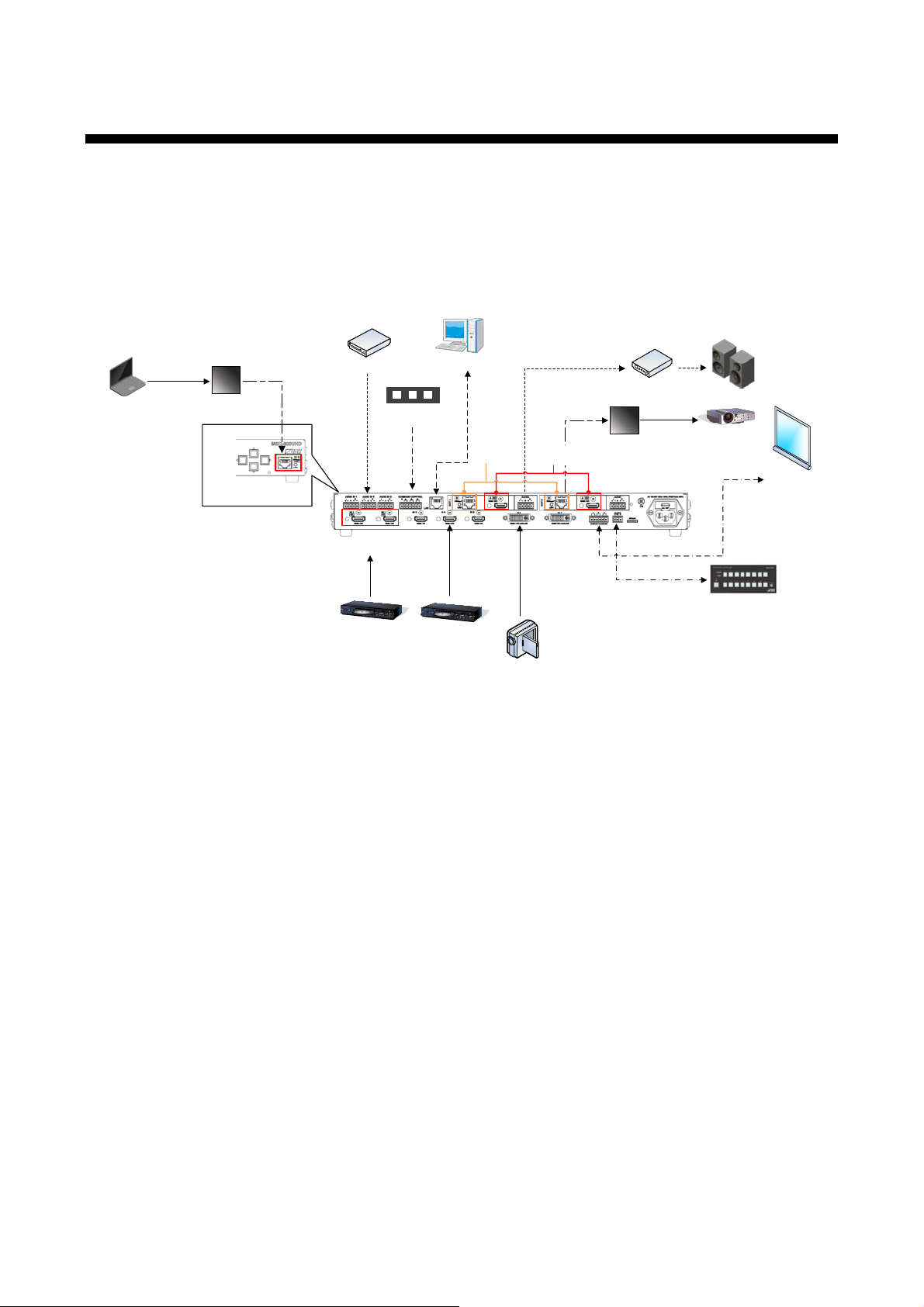
6 System configurati on exampl e
Configuration ex am ple: source and sink devices are connected to the MSD.
Use a transmitter that supports PoH PD (IEEE 802.3af) and AWG 24 twisted pair cable or thicker cable in
order to provi de power fr om the HDB aseT input connector on the front panel t o the twisted pai r c able
transmitter.
For long reach mode, please use the MSD with IDK’s twisted pair cable transmitter or receiver.
[Fig. 6.1] Configuration example (MSD-802UHD)
18
Page 19
MSD-701UHD / 702UHD / 801UHD/ 802UHD User’s Guide
7 Precautions
Before connecting to external devic es, follow the precautions below.
7.1 Installation
When installing the MSD, please observe the following prec autions.
● Do not stack or place one MSD directly on top of another MSD.
● Do not block vent holes. To provide adequate ventilati on, maintain sufficient clearanc es around t he
MSD 1.18 inches (30 mm).
● When the MSD needs to be mounted in an EIA rack, or an enclosed space, pl ease en sure t hat
sufficient v entilation or cooling i s provided and that the ambient temperatur e will not exceed 104°F
(40°C). If inadequately vented, the product ’s serv ice life, operation and reliability may be affected.
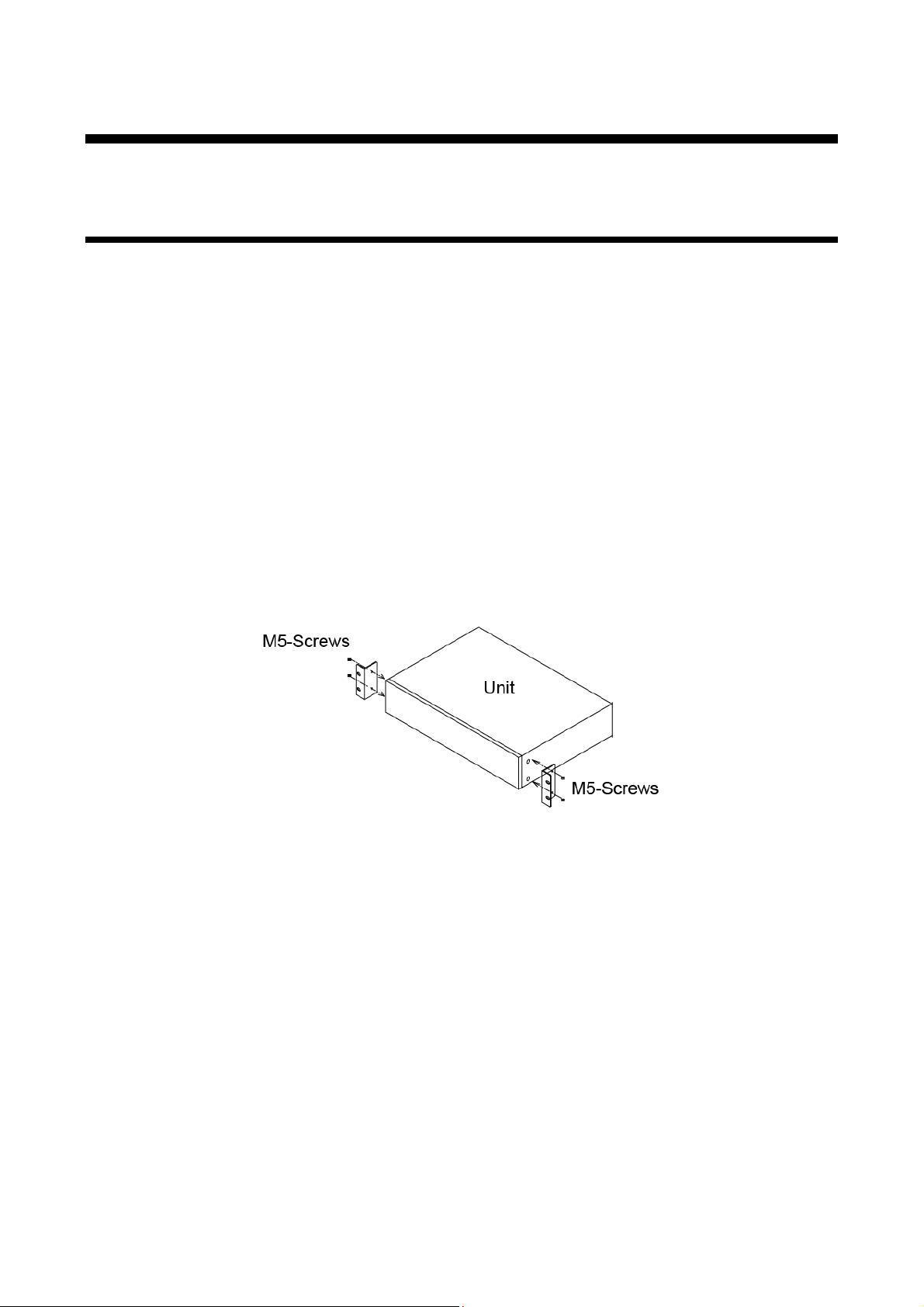
■ Attaching rack mounting bracket s
1. Remove four M5 screws fr om one si de of t he unit. Retain these screws for step 2.
2. Attach one brack et t o the side of t he unit using the screws removed in step 1.
3. Repeat steps 1 and 2 on the other side of the unit.
[Fig. 7.1] Attaching rack mounting brackets
Note:
The standard screw tightening torque is 2.94 N・m (about 30 kgf・cm).
19
Page 20
MSD-701UHD / 702UHD / 801UHD/ 802UHD User’s Guide
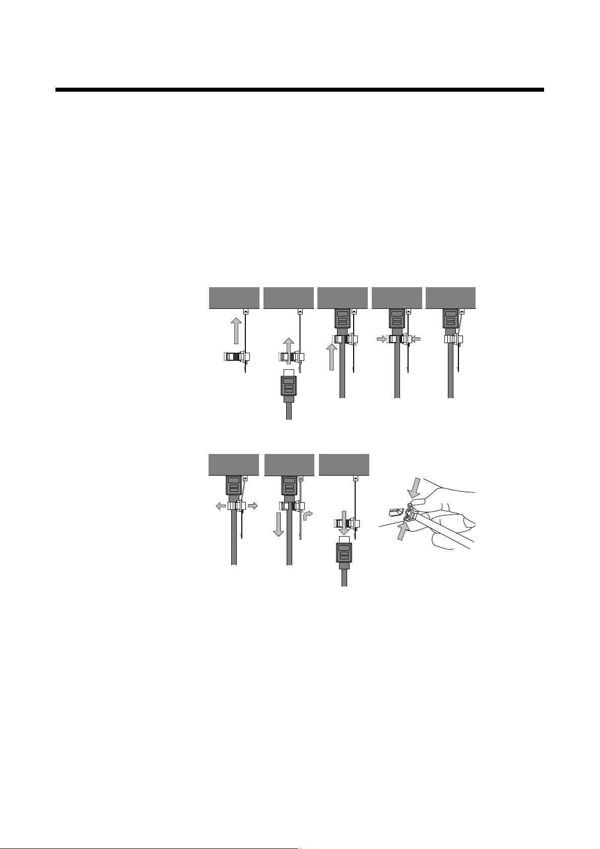
Fixing HDMI cable using cable clamp
Removing HDMI cable and cable clamp
①
②
③
Pull out while pressing
④
② ④ ⑤① ③
7.2 Cabling
When connecting the MSD to external devices, please observe the following precauti ons.
・Read manuals for the exter nal dev ices.
・ Before you connecti ng c ables to the MSD or an exter nal devic e, dissipate static electric ity by touching
grounded metal such as racks before handling signal cables. Failure to observe this precaution may
result in ESD (electrostatic discharge) damage.
・Power all units off before connecting cables.
・Be sure to fully seat all plugs and connections and dress cables to reduce str es s on connectors.
・Secure HDMI cables using cable clamps to prev ent connector s from being accidentl y pulled out of
ports.
20
[Fig. 7.2] Attaching a cable clamp
Page 21

MSD-701UHD / 702UHD / 801UHD/ 802UHD User’s Guide
7.2.1 Cables
IDK has a large selecti on of fl exi ble HDMI cables, DVI cables, high-quality long cables, and c onv er si on
cables.
Use the correct cable depending on the system configuration.
For analog audi o and RS-232C, select or fabricate cables to match the connectors as needed.
7.2.2 DVI-I input connector
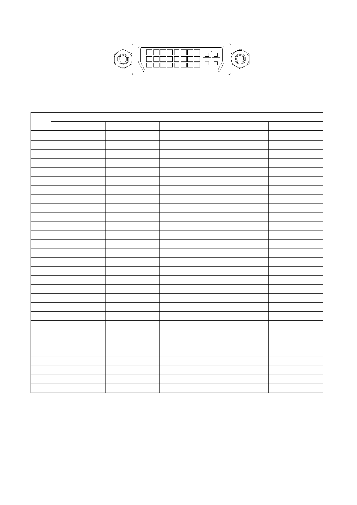
29-pin DVI-I female connect or s are used for DVI inputs.
The DVI-I input connectors can be used for HDMI/DVI digital signal s and for analog signal.
■ DVI signal input
Use DVI-I or DVI-D cable.
Signal only supports single-link.
■ HDMI signal input
Use HDMI-DVI conversion c able.
■ Analog RBG signal input
Use conversion cable whic h has DVI -I (m ale) and high-density D-sub 15 (f em ale) .
■ Other analog signal input
Analog YPbPr / composit e v ideo / Y/C signals can be input.
Use conversion c able for each signal.
Pin assignment s for each signal are shown below.
21
Page 22
MSD-701UHD / 702UHD / 801UHD/ 802UHD User’s Guide
1 2 3 4 5 6 7 8
9 10 11 12 13 14 15 16
17 18 19 20 21 22 23 24
C2C1
C3 C4
C5
Input signal name
HDMI / DVI
Analog RGB
Analog YPbPr
Composite video
Y/C
1
TMDS Data2-
N.C.
N.C.
N.C.
N.C.
2
TMDS Data2+
N.C.
N.C.
N.C.
N.C.
3
GND
N.C.
N.C.
N.C.
N.C.
4
N.C.
N.C.
N.C.
N.C.
N.C.
6
DDC Clock
DDC Clock
N.C.
N.C.
N.C.
14
+5V Power
N.C.
N.C.
N.C.
N.C.
16
Hot Plug Detect
N.C.
N.C.
N.C.
N.C.
17
TMDS Data0-
N.C.
N.C.
N.C.
N.C.
18
TMDS Data0+
N.C.
N.C.
N.C.
N.C.
19
GND
N.C.
N.C.
N.C.
N.C.
20
N.C.
N.C.
N.C.
N.C.
N.C.
21
N.C.
N.C.
N.C.
N.C.
N.C.
22
GND
N.C.
N.C.
N.C.
N.C.
24
TMDS Clock-
N.C.
N.C.
N.C.
N.C.
[Fig. 7.3] 29-pin DVI-I female connector
[Table 7.1] Pin assignment s
Pin #
5 N.C. N.C. N.C. N.C. N.C.
7 DDC Data DDC Data N.C. N.C. N.C.
8 N.C. V-Sync N.C. N.C. N.C.
9 TMDS Data1- N.C. N.C. N.C. N.C.
10 TMDS Data1+ N.C. N.C. N.C. N.C.
11 GND N.C. N.C. N.C. N.C.
12 N.C. N.C. N.C. N.C. N.C.
13 N.C. N.C. N.C. N.C. N.C.
15 GND N.C. N.C. N.C. N.C.
23 TMDS Clock+ N.C. N.C. N.C. N.C.
C1 N.C. Red Pr / Cr N.C. N.C.
C2 N.C. Green / SOG Y VIDEO Y
C3 N.C. Blue Pb / Cb N.C. C
C4 N.C. H-Sync / CS N.C. N.C. N.C.
C5 N.C. GND GND GND GND
N.C. : No Connecti on
SOG : Sync On Green
CS : Composite Sync
22
Page 23
MSD-701UHD / 702UHD / 801UHD/ 802UHD User’s Guide
Noise
influence
Category
Extension
distance
TMDS clock
Remarks
Easily
UTP
Cat5e
164 ft.
(50 m)
225 MHz
For 164 ft. (50 m) or longer,
Cat6
328 ft.
(100 m)
230 ft.
(70 m)
> 225 MHz
For 4K format 230 ft. (70 m) or
Less
STP
Cat5e*
328 ft.
Long reach mode
(1080p 24 bit or less)
Cat5e STP, Cat6 STP,
7.2.3 Twisted pair cable for extension
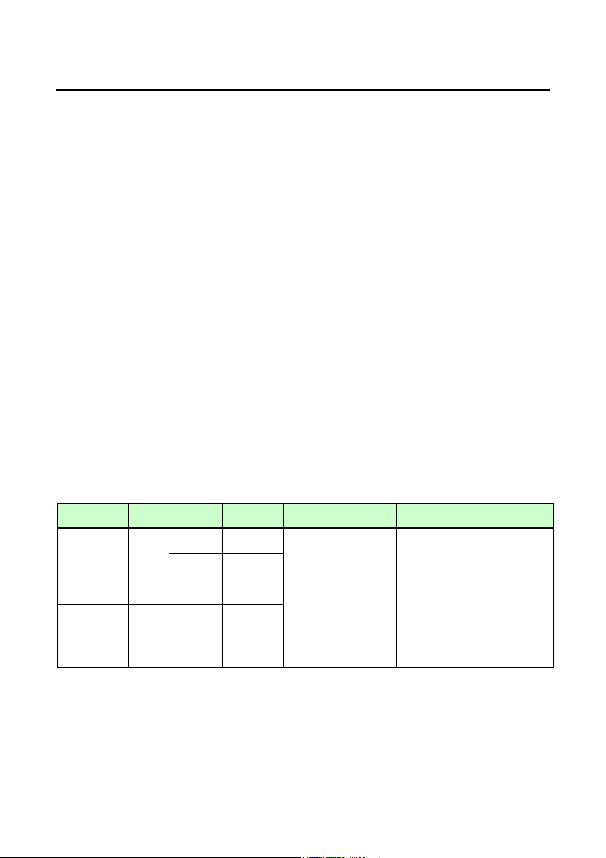
To ensure the best perf ormance of twisted pair cables, select a c or r ect twisted pair cable and connect it
correctly.
● Cat5e UTP/STP and Cat6 UTP/ STP can be used, but we recommend CAT.5E HDC cable* for optimal
performance.
● If using an STP cable, connect the FG connect or to a ground source. O therwise, t he shiel ding feat ure
does not work correctly . W hen usi ng a UTP c able, we still recommend using the ground connec t or.
● The shielded STP cables are less affected by interference or external noise than UTP cables.
● Connectors for long-haul extension are the sam e as that of eight-core modular connector used for
Ethernet, but t he transmission system is not the same so that it cannot be c onnec ted to Ethernet.
● The maximum extension distance of a twisted pair cables is the shorter distance of the maximum
extension distances of transmitter/r ec eiv er /sink device connected to the MSD.
● Pin assignment s: T568A or T568B str aight
● Do not pull the cable hard. The allowable tension of the twisted pair cable is 110 N.
● Do not bend the connection c able at a sharp angle. Keep the bend radius four times of the cable diameter
or larger.
● Do not tie the cable tightly ; leave a space allowing the cable t o move slightly.
● If you use multiple twisted pair cables, we recommended keeping a distance between the cables or not
to place the cables closel y in par allel.
● Keep the twisted pair cabl e as straight as you can. If you coil the cable, it i s easily affected by noise.
● Do not place the cable in an electrically noisy environment, since high-speed signals are transmitted.
Particularl y when you use a high-out put radio around the MSD, video or audio may be interrupted.
● If the total extension distance f rom the transmitter t o receiver is 328 ft. (100 m) or l ess, up to two cable
joints can be used. Products supporting Cat6A (10GBase-T) are recommended. However, the extension
distance of high-resolution transmission, such as 4K, may be short ened about 10%.
● Use AWG 24 or ticker cable for PoH.
● The table below shows supported extension distanc e for each twisted pair cable category. Note that the
distance may shorten depending on the actual environment.
[Table 7.2] Twisted pair cabl e and exten sion di st ance
affected
affected
*The CAT.5E HDC cable is a double-shi elded twisted pair c able that optimizes video signal t r ansmission.
It is certified to 500 MHz bandwidth at distance up to 330 feet (100 m) and verified to meet requirements
specified by HDB aseT Alli anc e. The double-shielded structur e protects video signal from outside
interference.
Note:
If there is a problem in the transmission path, video or audio may be interrupted. Check the precautions above.
If the problem still c annot be solved, shortening the twisted pair cable may remedy the pr oblem.
Cat6
(100 m)
492 ft.
(150 m)
≦
(4K format)
≦ 148 MHz
Cat5e STP, Cat6 UTP / STP,
CAT.5E HDC* are
recommended.
longer, Cat5e STP, Cat6 STP,
CAT.5E HDC* are
recommended.
CAT.5E HDC cable
23
Page 24
MSD-701UHD / 702UHD / 801UHD/ 802UHD User’s Guide
-
Unbalanced signal (input)
+
+
G
L
R
Lch
GND
Rch
Unbalanced signal (input/output)
-
+
+
G
L
R
Lch
GND
Rch
GND
GND
+
+
-
G
L
R
Lch +
Lch GND
Rch +
Rch -
Up t o 0.28" (7mm)
Balanced signal (input/output)
Up t o 0.28" (7mm)
Up t o 0.28" (7mm)
Tx
Rx
GND
RS-232C Tx
RS-232C Rx
GND
Up to 0.28" (7mm)
7.2.4 Connecting audio cables
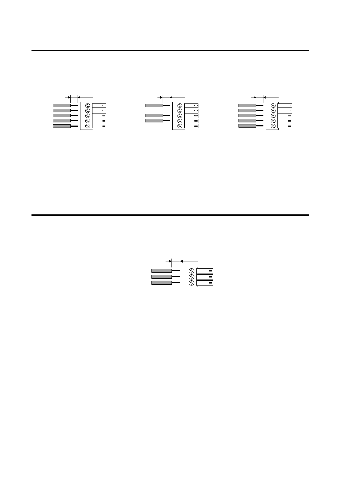
Connect audio cables to the 5-pin terminal block. The MSD supports both balanced and unbalanced analog
signals.
AWG28 to AWG16 conduc tor gauge is recommended. The recommended wire strip length is 0.28 in. (7 mm).
[Fig. 7.4] Connecting audio cable to 5-pin terminal block connector
7.2.5 Connecting RS-232C cable
A 3-pin terminal block is used for the RS-232C connector.
Fix RS-232C cable to the attached3-pin terminal block, and then connect it to the MSD.
AWG28 to AWG16 conduc tor gauge is recommended. The recommended wire strip length is 0.28 in. (7 mm).
[Fig. 7.5] Connecting RS-232C cable to 3-pin terminal block connector
24
Page 25
MSD-701UHD / 702UHD / 801UHD/ 802UHD User’s Guide
1
2
Up to 0.28" (7mm)
3
COMMAND A-BUTTON
Up to 0.28" (7mm)
GND
COMMAND A-LAMP
COMMAND B-BUTTON
COMMAND B-LAMP
COMMAND C-BUTTON
COMMAND C-LAMP
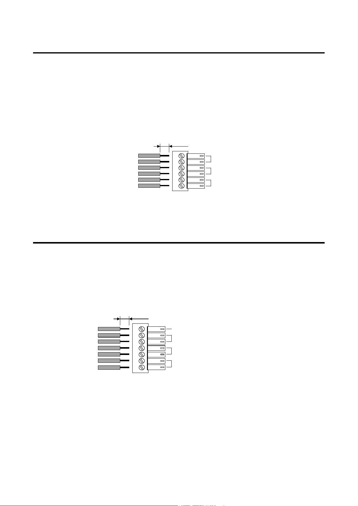
7.2.6 Contact closure
The MSD has a total of three (3) independently controlled cont ac t closure channels for ext er nal c ontrol.
Each connector supports three (3) channels. The maximum peak load for each contact is 24 VDC @ 500 mA.
Connect a cable to the 6-pin terminal block, and then insert int o the appropr iate connector on the MSD’s rear
panel.
AWG28 to AWG16 conduc tor gauge is recommended. The recommended wire strip length is 0.28 in. (7 mm).
[Fig. 7.6] Connecting cable to 6-pin terminal block connector
7.2.7 Command control
Up to three command buttons (comm ands A to C) can be executed by connecting the provided 7-pin terminal
block to the command cont r ol c onnec tor.
Connect these butt ons for control commands A to C and LAMPs to the termi nal block. When 0V (GND) is
input to the BUTTON terminal, the command will be executed. The LAMP termi nal is controlled with DC
5V/100mA. For LE Ds, a current-limiting resistor has to be connect ed.
AWG28 to AWG16 conductor gauge is recommended. The recomm ended wir e stri p length is 0.28 in. (7 mm).
[Fig. 7.7] Connecting cable to 7-pin terminal block connector
25
Page 26
MSD-701UHD / 702UHD / 801UHD/ 802UHD User’s Guide
Switching mode
Description
V&A
Video&Audio simult aneousl y
VIDEO
Video
AUDIO
Audio
Output ting inpu t signals of I N1 to OUT1
Output ting inpu t signals of I N3 to OUT2
MSD-802UHD
[ V&A ]
Top
8 Basic operation
8.1 Power up init per i o d
After poweri ng on the MSD, there is some seconds initialization delay before the WEB browser is fully
operational and before the first communication command can be received and executed.
[Table 8.1] Required time
Operation Required time
Receiving comm unic ation command 11 seconds
Receiving WEB browser operati on 11 seconds
Receiving oper ation of front panel 12 or longer seconds
Note:
If “9.15.7 Startup bitma p output” is set to “ON”, the required time for the front panel operation may be longer.
8.2 Switching input channel
8.2.1 Selecting input channels
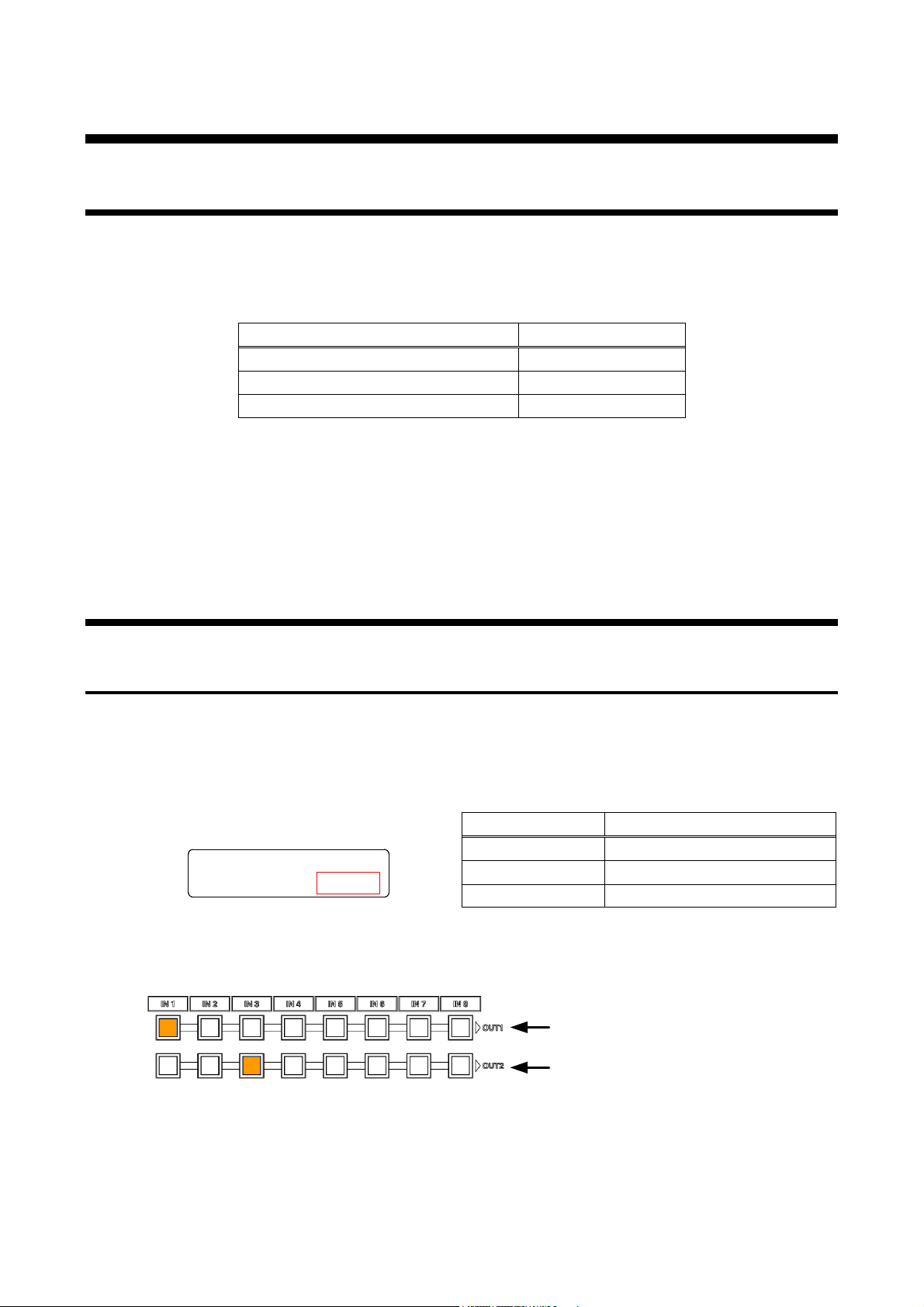
Video and audio si gnals can be switched simultaneously or independently.
Select the desired m ode and pr ess the i nput channel selection key, and t hen sel ec t t he output channel.
[Table 8.2] Switching mode
[Fig. 8.1] Switching mode
26
[Fig. 8.2] I/O cross point indication
Page 27
MSD-701UHD / 702UHD / 801UHD/ 802UHD User’s Guide
No t outputting s ignals to O UT 1
Output t ing input sig nals of I N3 to OUT2
No t outputting s ignals to O UT 1
Output t ing input sig nals of I N3 to OUT2
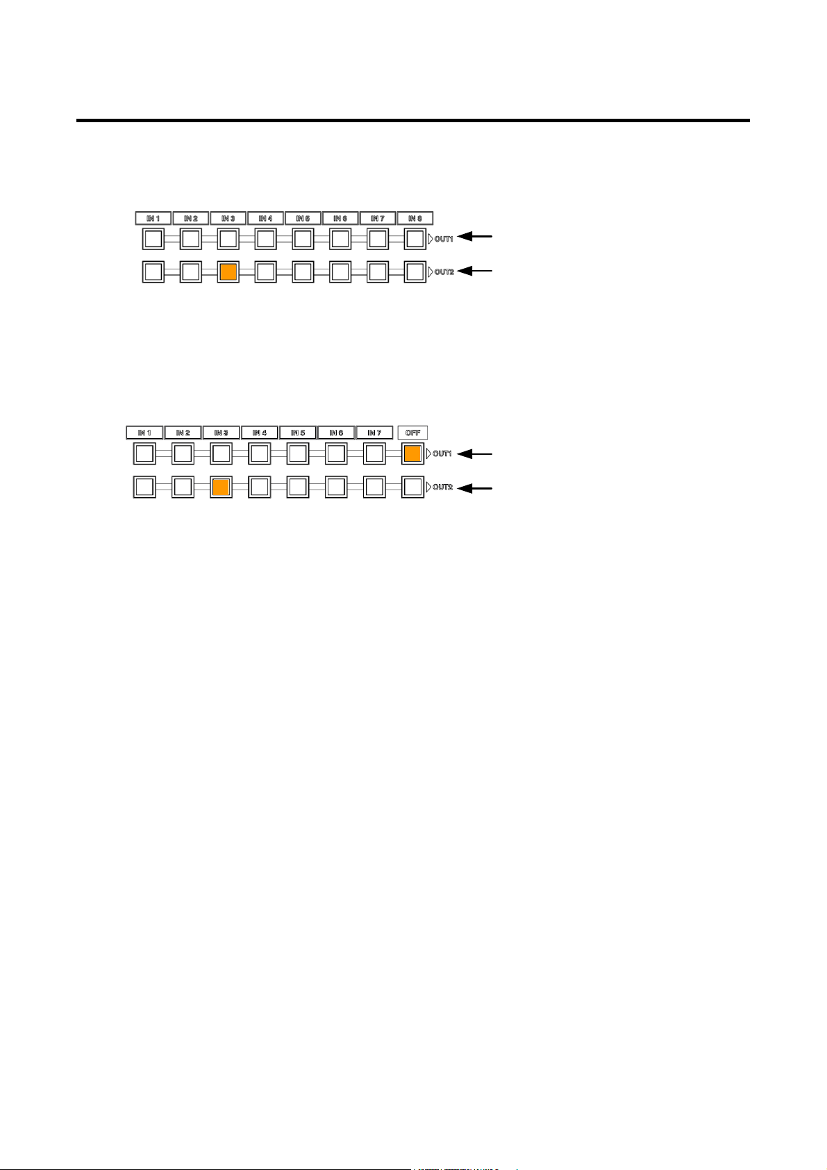
8.2.2 Turning off input signal
■ MSD-802UHD / MSD-801UHD
You can disable the input signal by pressing the input key that is currently selected. You can enable or disable
the input signal by toggle operation.
[Fig. 8.3] Input selection: OFF (MSD-802UHD)
■ MSD-702UHD / MSD-701UHD
To stop outputting si gnals, press the “OFF” button of OUT1 or OUT 2.
[Fig. 8.4] Input selection: OFF (MSD-702UHD)
27
Page 28
MSD-701UHD / 702UHD / 801UHD/ 802UHD User’s Guide
Top screen
Main menu
Setting
Sub menu
“MENU/SET” key
“ESC” key
Operation
MSD-802UHD
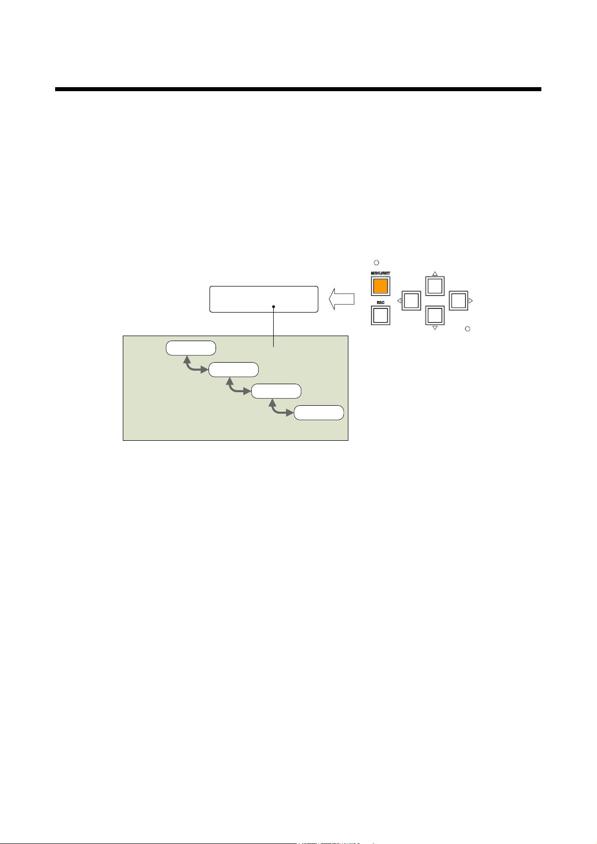
8.3 Menu opera ti on
You can use the VFD screen and front panel keys to view and control settings.
Press the “MENU/SET ” key to apply settings and to change the menu level.
Press the “ESC” key to go back to the pr ev ious screen.
Use the “▲” and “▼” keys to select channels and use the “▲” and “▼” keys to select the menu item.
In the setting screen, use “▲”, “▼”, “▲” and “▼” keys to move the cursor and select t he setting The applied
values are saved automatically after the session .
【See: 9.1 Menu list】
[Fig. 8.5] Menu level
Tip:
The “MENU/SET” key LED is illuminated only for settable menu.
For some setting screens, t he set v alue is applied from the “MENU/SET” key. When the “MENU/SET” key
flashes, press the key to apply the setting value. After the setting has been applied, the key will illuminate
without flashing.
We offer an optional cover for menu operation keys to prevent accidental key presses. P lease contact us as
needed.
Note:
To avoid losing settings, do not interr upt power to the MSD while “NOW SAVING” is displayed; otherwise, the
setting information may be lost.
28
Page 29
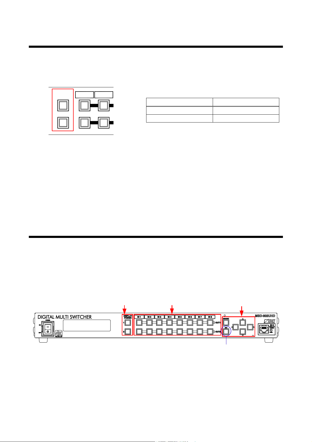
MSD-701UHD / 702UHD / 801UHD/ 802UHD User’s Guide
DISPLAY POWER keys
Input cha nnel select i on keys
Menu/operation keys
Press and hol d the “UNLOCK” ke y for
2 seconds or longer to set/ca n cel ke y lock
Sink device power status
LED
IN 2IN 1
DISPLAY
POW ER
1
2
8.4 Menu opera ti on
You can register control commands to power the sink devi c e on/off. By pressing the appropriate key, control
commands are sent to the sink dev ic e.
【See: 9.13.3 Command link】
[Table 8.3] Sink device power suppl y key
Power ON Lights (orange)
Power OFF Turned off
[Fig. 8.6] Sink device power control key
Note:
If power a ON/OFF control command is sent to a sink device and reply command of normal termination is sent
from the sink device, the “DISPLAY POWER” key turns orange (when powered ON) or the key light turns off
(when powered OFF).
If the reply command from the si nk dev ic e is not c hec ked, the actual power status of the sink dev ic e and the
LED may not match.
8.5 Locking and unlocking keys
Press and hold the “UNLOCK” key for 2 seconds or longer t o set/cancel keylock function for keys below. You
will hear a beep and then one of the following messages i s di spl ay ed for 1 second.
【See: 9.17.1 Grouping key function lock】
・OPERATION LOCK ! (Locked)
・OP LOCK RELEASE ! (Unlocked)
[Fig. 8.7] Keys to be set/cancel operation lock (MSD-802HUD)
29
Page 30
MSD-701UHD / 702UHD / 801UHD/ 802UHD User’s Guide
OUTPUT TIMING
Default
105 % [NTSC / PAL / SDTV input]
V : 0
INPUT SI ZE
For
Each input channel, each input signal
P.51
Default
H : Horizontal output resol ution
T : 0
B : Vertical i nput siz e
Default
---
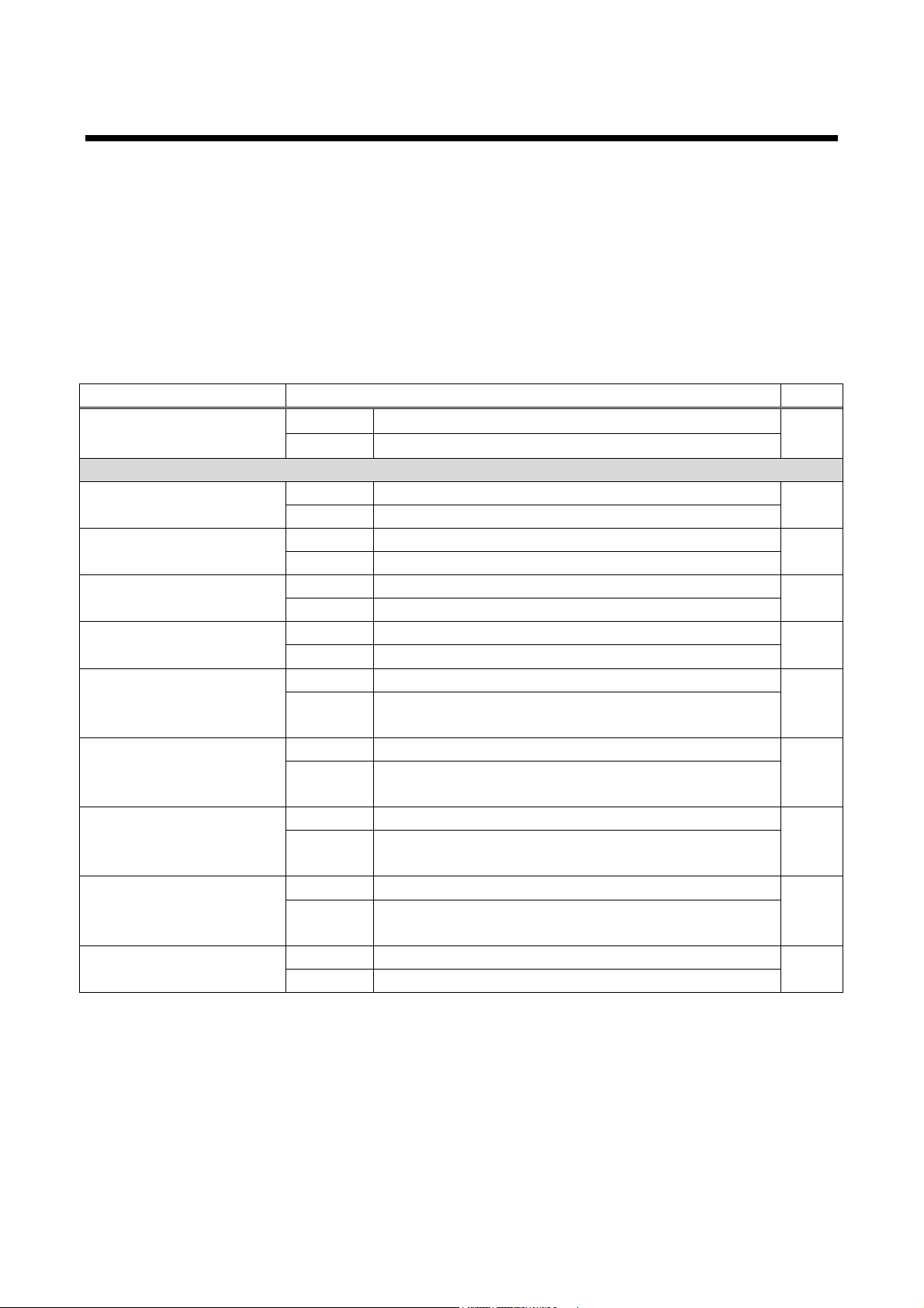
8.6 Initialization
All settings will be reset to factory default values by tur ning on the MSD while pressing the “ESC” key.
Press and hold the “ESC” key until y ou hear a long beep sound.
Table 8.4 below, shows the Factory default values.
When settings are i nitialized from the WEB browser, they can be initialized without changing LAN settings.
Note that after returning to factory default, the previ ous setting v alues cannot be restored. Som e menus can
be set for each input channel and output channel individually; see “[Table 8.14] Setting condition” for
details.
[Table 8.4] Factory default
Menu Factory defaul t See
SWITCHING MODE For --- P.46
Default V&A
RESOLUTION For Each output channel P.47
Default AUTO-A
MONITOR ASPECT For Each output c hannel P.49
Default RESOLUTION
INPUT ASPECT For Each input channel, each input signal P.49
Default AUTO-1
ASPECT PROCESS For Each input channel, each input signal P.50
Default L-BOX / S-PANEL
INPUT OVER SCAN For Each input channel, each input signal P.50
100 % [HDTV / PC input]
INPUT POS ITION For Each input channel, each input signal P.50
Default H : 0
V : Vertical output resolution
INPUT MASKING For Each i nput channel, each input signal P.52
Default L : 0 R : Horizontal input size
INPUT AUTO SIZING For Each i nput channel, each input signal P.52
30
Page 31
MSD-701UHD / 702UHD / 801UHD/ 802UHD User’s Guide
V : 0
OUTPUT SIZE
For
Each output channel
P.51
V : Vertical input size
Default
L : 0
R : Horizontal input size
B : 0
TEST PATTERN
For
Each output channel
P.53
Default
OFF
IMAGE EFFECT
INPUT SHARPNESS
For
Each input channel, each input signal
P.54
Default
0
INPUT BRIGHTNESS
For
Each input channel, each input signal
P.54
Default
100 %
For
Each input channel, each input signal
Default
R : 100 %
B : 100 %
For
Each output channel
Default
100 %
For
Each output channel
Default
R : 100 %
B : 100 %
OUTPUT GAMMA
For
Each output channel
P.55
Default
1.0
OUT DEFAULT COLOR
For
Each output channel
P.56
Default
---
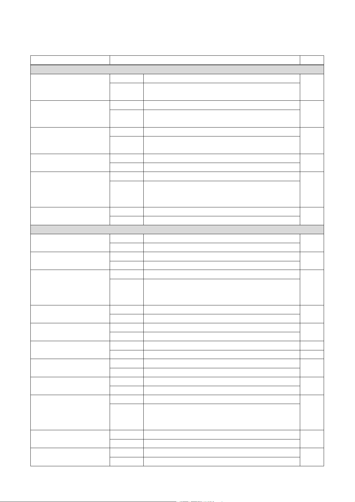
[Table 8.5] Factory default (Cont’d)
Menu Factory defaul t See:
OUTPUT TIMING
OUTPUT POSITION For Each output c hannel P.50
Default H : 0
Default H : Horizontal input size
OUTPUT MASKING For Each output channel P.52
T : 0 B : Vertical input size
OUTPUT AUTO SIZING For Each output channel P.52
Default ---
BACKGROUND COLOR For Each output c hannel P.53
Default R : 0
G : 0
INPUT CONTRAST
P.54
G : 100 %
INPUT HUE For Eac h input channel, each input signal P.55
Default 0 °
INPUT SATU R ATION For Each input channel, each input signal P.55
Default 100 %
INPUT SETUP LEVEL For Each input channel , each input signal P.55
Default 0.0 %
IN DEFAULT COLOR For Each input channel, each input signal P.56
Default --OUTPUT BRIGHTNESS
OUTPUT CONTRAST
P.54
P.54
G : 100 %
31
Page 32
MSD-701UHD / 702UHD / 801UHD/ 802UHD User’s Guide
Default
HDCP 2.2 [IN1, IN2, IN8]
Default
OFF
INPUT TABLE FIXED
For
Each input channel
P.61
analog input only*1
analog input only*1
Default
Depends on input signal
H START
For
Each input channel, each input signal
P.65
Default
Depends on input signal
H DISPLAY
For
Each input channel, each input signal
P.66
Default
Depends on input signal
For
Each input channel, each input signal
Default
Depends on input signal
Default
Depends on input signal
analog input only*1
Default
ON
UNKNOWN TIMING
For
---
P.67
Default
AUTO SETUP ON
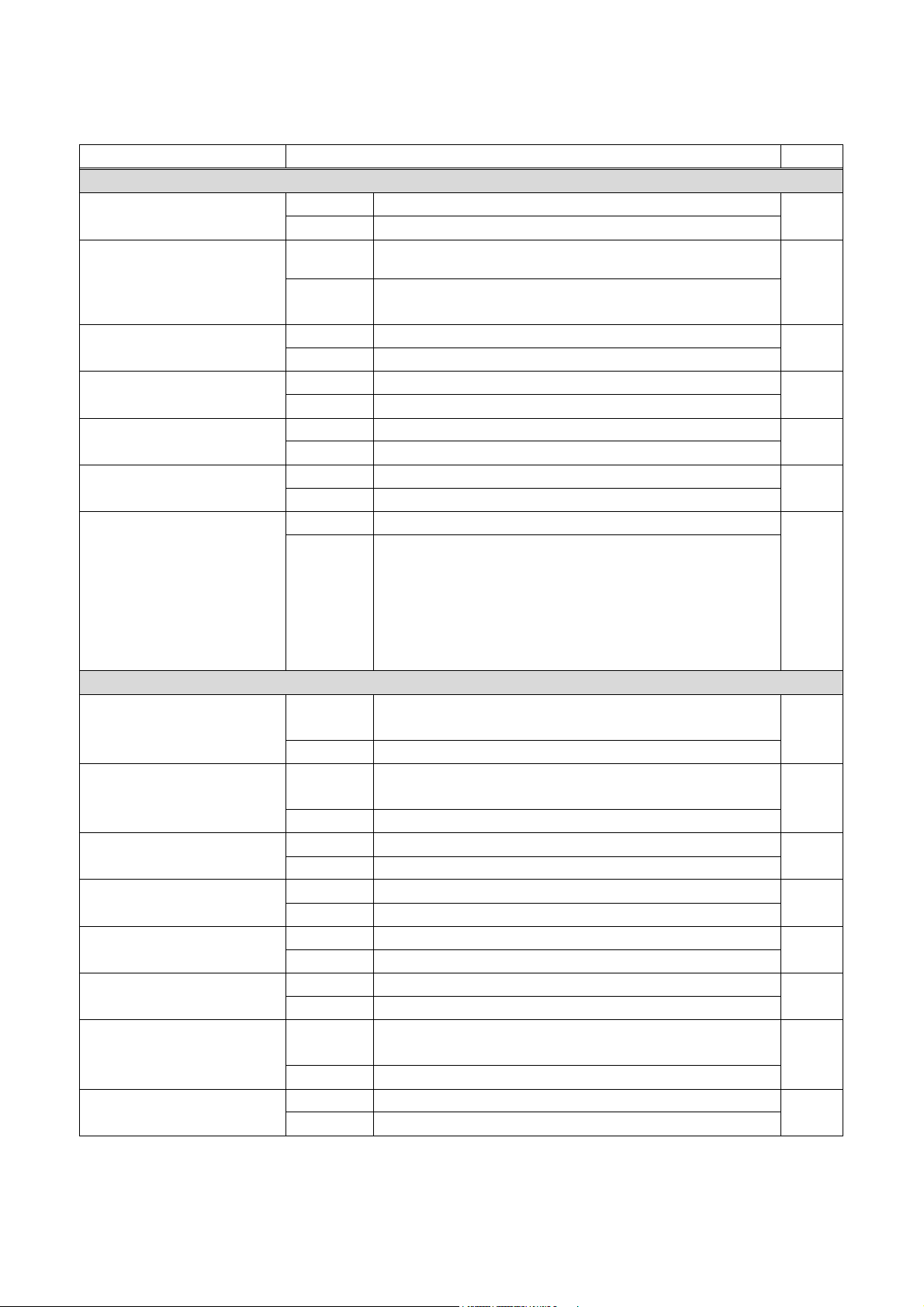
[Table 8.6] Factory default (Cont’d)
Menu Factory defaul t See:
INPUT SET TING
INPUT VIDEO DETECT For Each input channel, digital input only P.57
Default 10000 ms
HDCP INPUT ENABLE For Each input channel, digital input only P.58
HDCP 1.4 [IN3 to IN7]
ANALOG INPUT TYPE For Each i nput channel, each input signal, analog input only P.59
Default AUTO
INPUT OFF CHECK For Each i nput channel P.60
Default ON
INPUT AD TYPE For Each input channel, DVI connector only P.60
Default DIGITAL
LONG REACH MODE For HDBaseT input channel P.60
Default [Setting mode]
SELECTED
[Individual sett ing (“SELECTED” is selected for setting
mode)]
ASPECT : OFF, ANALOG TYPE : ON(FIXED)
AUDIO LEVEL : ON(FIXED)
INPUT TIM ING
AUTO SETUP
For Each input channel, each input signal,
P.63
Default NORMAL MODE
H TOTAL DOTS For Each input channel, each input signal,
V START
P.65
P.65
V DISPLAY For Each input channel, each input signal P.66
AUTO START POS For Each input channel, each input signal,
*1
Can be set and executed only if an analog RGB or YPbPr signal input is activ e.
32
P.67
Page 33
MSD-701UHD / 702UHD / 801UHD/ 802UHD User’s Guide
Default
0
OUTPUT SETTING
OUTPUT MODE
For
Each output channel
P.69
Default
HDMI YCbCr 4:4:4 MODE
SYNC OUTPUT
For
Each output channel
P.69
Default
ON
VIDEO OUTPUT
For
Each output channel
P.70
Default
BLUE
For
Each output channel
Default
FREEZE→FADE OUT-IN
For
Each output channel
For
Each output channel
Default
24-BIT COLOR
For
Each output channel
Default
NOT CONNECTED
HDCP AUTHORIZATION
For
Each output channel
P.73
Default
---
AUTO SWITCHING ON
For
Each output channel
P.74
Default
OFF
For
Each output channel
Default
OFF
Default
0s000ms
[Table 8.7] Factory default (Cont’d)
Menu Factory defaul t See:
INPUT TIM ING
LOAD For Each input channel, each input signal P.68
Default ---
SAVE For each input si gnal, each input signal*1 P.68
Default ---
TRACKING For Each input channel , each input signal*1 P.68
VIDEO SWITCHING
P.70
SWITCHING SPEED For Each output channel P.70
Default 350 ms
WIPE COLOR For Eac h output channel P.70
Default R : 0, G : 0, B : 0
OUTPUT CONNECTOR For Each output c hannel P.71
Default ON
HDCP OUTPUT MODE For Each output channel P.71
Default HDCP 2.2
HDCP ERROR RETRY
P.72
Default ETERNITY
DEEP COLOR OUTPUT
CEC CONNECTION
P.72
P.73
AUTO SWITCHING OFF
AUTO SWITCHING MASK For Each output channel P.76
AUTO SWITCHING MODE For Each out put channel P.76
LONG REACH MODE For Each output channel P.76
P.74
Default V&A
Default OFF
33
Page 34
MSD-701UHD / 702UHD / 801UHD/ 802UHD User’s Guide
Default
DIGITAL
INPUT OFFSET
For
Each input channel, each input signal
P.78
Default
0 dB
OUTPUT LIP SYNC
For
Each output channel
P.79
Default
0 FRAME
INPUT LIP SYNC
For
Each input channel, each input signal
P.79
Default
0 FRAME
For
Each output channel
Default
AUTO-A
For
Each output channel
SPEAKER : ALL
[Table 8.8] Factory default (Cont’d)
Menu Factory defaul t See:
AUDIO
OUTPUT LEVEL For Each output c hannel P.78
Default 0 dB
OUTPUT MUTE For Eac h output channel P.78
Default OFF
AUDIO INPUT SELECT For Each i nput channel, digital input only P.78
SAMPLING FREQUENCY
AUDIO OU TP U T
Default ANALOG&DIGITAL
DIGITAL OUTPUT For Each output channel P.80
Default ON
MULTI AUDIO For E ac h output channel P.80
Default DO WN MIX
OUT AUDI O PRIORITY For Each output channel P.81
Default MULTI
TEST TONE For Each output channel P.82
Default TEST TONE : OFF
P.79
P.80
34
Page 35
MSD-701UHD / 702UHD / 801UHD/ 802UHD User’s Guide
IN8 : 2160p@30 (3840x2160)
Default
AUTO
DEEP COLOR INPUT
For
Each input channel, digital input only*2
P.87
Default
24-BIT COLOR
AUDIO FORMAT
For
Each input channel, digital input only*2
P.87
Default
PCM : 48 kHz
[Table 8.9] Factory default (Cont’d)
Menu Factory defaul t See:
EDID
EDID DATA For Each input channel, digital input only P.83
Default INTERNAL EDID
PC RESOLUTION For Each input channel P.84
Default IN1 to IN2 : 2160p@60 (3840x2160)
IN4 to IN7 : 1080p(1920x1080)
AV RESOLUTION For Each i nput channel, digital input only*2 P.86
Dolby Digital : OFF
AAC : OFF
Dolby Digital+ : OFF
DTS : OFF
DTS-HD : OFF
Dolby TrueHD : OFF
SPEAKER For Each input channel, digital input only*2 P.88
Default MODE : AUTO
NUMBER : 2
FL / FR : ON
LFE : OFF
FC : OFF
RL / RR : OFF
RC : OFF
FLC / FRC : OFF
RLC / RRC : OFF
FLW / FRW : OFF
FLH / RLH : OFF
TC : OFF
FCH : OFF
FCH : OFF
MONITOR EDID COPY For No.1 to No.8 P.89
Default ---
*2
Can be set only if “INTERNAL EDID” is selected for the EDID mode.
35
Page 36
MSD-701UHD / 702UHD / 801UHD/ 802UHD User’s Guide
For
EACH RS-232C CHANNEL
Default
192.168.1.200
Default
Operation mode : RECEIVER
PASS WORD : 20 in ASCII (Space)
PORT NUMBER
For
Each connecti on
P.95
Default
Connection1 to Connection3 : 1100
Connection7 to Connection8 : 80
For
---
Default
---
[Table 8.10] Factory default (Cont’d)
Menu Factory defaul t See:
COM PORT
PARAMETERS For EA CH RS -232C CHA NNE L P.90
Default Baud rate : 9600
Data bit length : 8
Parity check : NONE
Stop bit : 1
FUNCTION
Default RECEIVER (Receiver mode)
OUT B SCI CONNECT For --- P.91
Default OFF
LAN
IP ADDRESS For --- P.94
Default 192.168.1.199
SUBNET MASK For --- P.94
Default 255.255.255.0
GATEWAY ADDRESS For --- P.94
P.91
FUNCTION For Each connection P.94
IP address : 192.168.1.198
PJLink : OFF
PORT : 1100
Connection4 to Connection6 : 23
MAC ADDRESS
P.95
36
Page 37
MSD-701UHD / 702UHD / 801UHD/ 802UHD User’s Guide
[Table 9.21] Setting items of control command
[Table 9.26] Setting it ems of return command
Default
OFF
COMMAND EXECUTION
For
---
P.107
Default
---
INVALID TIME
Set value
0s000ms to 999s999ms
P.107
For
---
Default
0s000ms
INITIALIZE
For
---
P.107
Default
---
For
Each control comm and ex ec ution key
Default
REGISTERED
power key
Default
EXECUTION
PRESET MEMORY
LOAD CROSS POINT
For
---
P.109
Default
---
SAVE CROSS POINT
For
---
P.109
Default
---
For
Each cross point memory
[Table 8.11] Factory default (Cont’d)
Menu Factory defaul t See:
PRESET COMMAND
COMMAND EDIT For E ac h c ontrol command P.98
Default “
”
RECV COMMAND EDIT For Eac h r eply command P.103
Default “
”
COMMAND LINK For Eac h c ontrol command executi on condi tion P.106
COMMAND TALLY
FLASH TIM E For Each control comm and ex ec ution key, each sink device
EDIT CROSS POINT
P.108
P.108
P.110
Default Video input channel : ---
Audio input channel : --Memory name : 20 (space)
LOAD ALL SETTING For --- P.110
Default --SAVE ALL SETTING For --- P.111
Default --COPY OUTPUT MEMORY For --- P.112
Default --STARTUP For --- P.113
Default LAST CHA NNE L
37
Page 38
MSD-701UHD / 702UHD / 801UHD/ 802UHD User’s Guide
B : 255
ASPECT
For
Each output channel, eac h bitmap
P.116
Default
AUTO
For
Each output channel, eac h bitmap
Default
CENTER
Default
OFF
For
Each output channel
SIZE : 127
VIDEO CAPTURE
For
---
P.120
COM PORT
[Table 8.12] Factory default (Cont’d)
Menu Factory defaul t See:
BITMAP
BITMAP OUTPUT For E ac h output channel P.116
Default OFF
BACKGROUND COLOR For Each output c hannel, each bitmap P.116
Default R : 255
G : 255
POSITION
P.117
CHANNEL ASSIGN For Each output c hannel P.117
POWER ON BITMAP
P.117
Default OFF
DIVIDE MEMORY*3 For --- P.118
Default MODE : RESIZE
NUMBER : 1
DISPLAY : BLOCK
Default ---
DISPLAY POWER For Each out put channel P.122
Default AUTO
OPERATION LOCK For --- P.123
Default AUTO
*3
The registered bitmaps are not initialized by the init ialization.
38
Page 39
MSD-701UHD / 702UHD / 801UHD/ 802UHD User’s Guide
DISPLAY POW
Default
LOCK
For
---
Default
ON
POWER SAVE
For
---
P.125
Default
ON
DISP POW BU TT ON ON
For
---
P.125
Default
0 ms
For
---
Default
OFF
Default
NORMAL
[Table 8.13] Factory default (Cont’d)
Menu Factory defaul t See:
OTHERS
OP LOCK MODE For CHANNEL
CHANNEL MODE
MENU
COMMAND
P.124
BUZZER
HDC POWER OUTPUT
TOP DISPLAY For --- P.126
INPUT STA TU S For --- P.127
Default --MONITOR STATUS For --- P.129
Default --EDID STATUS For --- P.131
Default --VERSION For --- P.132
Default ---
P.125
P.125
39
Page 40
MSD-701UHD / 702UHD / 801UHD/ 802UHD User’s Guide
OUTB*4)
Setting is common to OUTA and OUTB
(Each OUTA / OUTB)
Can be set for each output channel s
Each input signal
Can be set for each input signal
Each input channel
Can be set for each input channel only if input
analog input only
channel is analog si gnal
Each input channel
Can be set for each input channel of DVI input
Each connecti on
Can be set for LAN connection
Each bitmap
Can be set for each bitmap
[Table 8.14] Setting condition
Setting range Description
Each output channel (Common to OUTA /
Can be set for each output channel
Can be set for OUTA and OUTB separately
(only OUTA) Can be set for OUTA
(only OUTB) Can be set for OUTB
Each input channel Can be set for each input channel
digital input only
Each input channel
DVI connector only
channel is digital signal
Can be set for each input channel only if input
connector
EACH RS-232C CHANNEL Can be set for RC-232C channel
*4
OUTA: HDMI output connect or , OUTB: HDBaseT out put connector
40
Page 41
MSD-701UHD / 702UHD / 801UHD/ 802UHD User’s Guide
80 (Normal)
http://192.168.1.199
8.7 Web menu operation
The MSD connected through a LA N can be cont r olled from a WEB browser, such as Microsoft Internet
Explorer. JavaS c ri pt is used for the WEB browser screen. To do thi s, make sure to enable JavaScript of the
WEB browser by referring to the HELP of each WEB browser.
Tip:
Compatibili ty has been tested and verified using t he following sy stem configurati on:
OS: Windows 7 Professional
WEB browser: Microsoft I nternet Explorer 11
Google Chrome 56
Mozilla Firefox 51
8.7.1 Control from WEB browser
To control the MSD from a WEB browser, enter t he IP address that is programmed into the MSD in the
address bar of the WEB browser to display the WEB menu. Not e that the default IP address for all MSD:
192.168.1.199
【See: 9.12.1 IP address/Subnet mask/Gateway address】
【See: 9.12.3 TCP port number】
[Table 8.15] Address input example
Control port number of web browser IP address (URL)
Other than 80 (5000 to 5999) http://192.168.1.199:5000 (ex: 5000)
41
Page 42
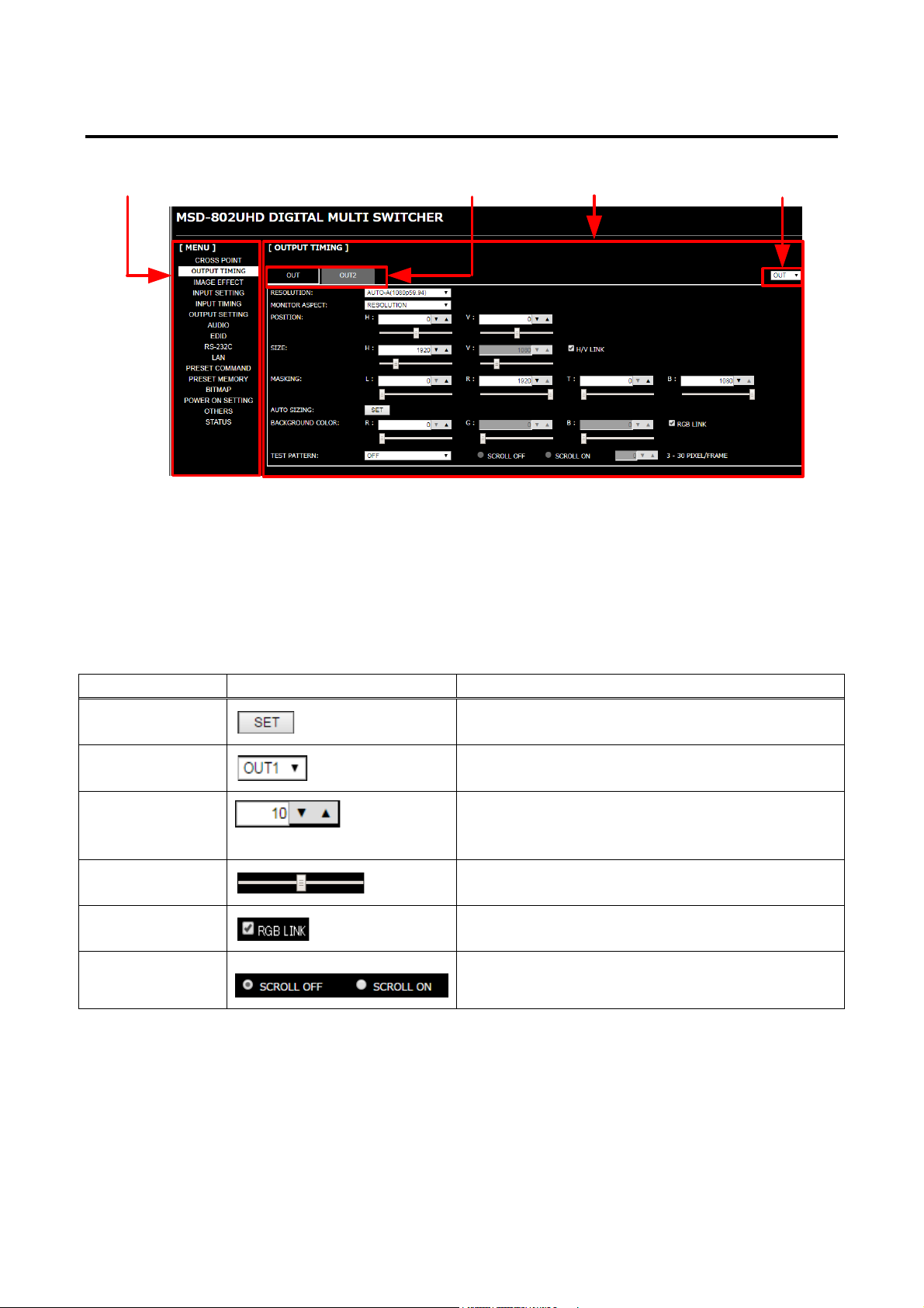
MSD-701UHD / 702UHD / 801UHD/ 802UHD User’s Guide
Menu
Tab Submenu
IN/OUT
Pull-down list
Selects the desir ed v alue.
Slider bar
You can move the slider to set t he desired value.
Radio button
Selects the desir ed v alue.
8.7.2 How to use WEB menu
[Fig. 8.6] WEB menu
① Select the target item from the menu.
Settings will be displ ay ed in the sub menu.
② If there is a setting item that can be set for each channel , channel tab will be displayed.
③ Configure each setting from the submenu by following the table below.
[Table 8.16] Buttons for setting
Button name Button Description
Execution butt on
Spin button
Check box
Tip:
You can change the channel nam e displ ay ed in the tab from “NAME EDIT” in the “CROSS POINT”.
Executes the target operation.
Selects the desir ed v alue.
You can type the desired value directly in the text
area.
Enables and disables by clicking or unclicking the box.
42
Page 43
Top
├─
│ ├─
│ ├
9 Menu
9.1 Menu list
Menu trees for the MSD
Main menu
Sub menu
MSD-801UHD
MSD-802UHD
MSD-701UHD
MSD-702UHD
│/*9.3 Channel switching mode*/
├─SWITCHING MODE
│/*9.4 Setting posi tion, size, and masking*/
├─OUTPUT TIMING
│ ├─RESOLUTION
│ ├─MONITOR ASPECT
│ ├─INPUT ASPECT
│ ├─ASPECT PROCESS
│ ├─INPUT OVER SCAN
│ ├─INPUT POSITION
│ ├─INPUT SIZ E
│ ├─INPUT MASKING
│ ├─INPUT AUTO S IZING
│ ├─OUTPUT POSITION
│ ├─OUTPUT SIZE
│ ├─OUTPUT MASKING
│ ├─OUTPUT AUTO SIZING
│ ├─BACKGROUND COLOR
│ └─TEST PATTERN
│
│/*9.5 Quality setting*/
├─IMAGE EFFECT
│ ├─INPUT SHARPNESS
│ ├─INPUT BRIGHTNESS
│ ├─INPUT CONTRAST
│ ├─INPUT HUE
│ ├─INPUT SATURATION
│ ├─INPUT SETUP LEVEL
│ ├─IN DEFAULT COLOR
│ ├─OUTPUT BRIGHTNESS
│ ├─OUTPUT CONTRAST
│ ├─OUTPUT GAMMA
│ └─OUT DEFAULT COLOR
│
[Fig. 9.1] Menu list (1/2)
MSD-701UHD / 702UHD / 801UHD/ 802UHD User’s Guide
│/*9.6 Input settings*/
├─INPUT SETTING
│ ├─INPUT VIDEO DETECT
│ ├─HDCP INPUT ENABLE
│ ├─ANALOG INPUT TYPE
│ ├─INPUT OFF CHECK
│ ├─INPUT AD TYPE
│ ├─LONG REACH MODE
│ └─INPUT TABLE FIXED
│
│/*9.7 Setting input t iming*/
├─INPUT TIMING
│ ├─AUTO SETUP
│ ├─H TOTAL DOTS
│ ├─H START
│ ├─H DISPLAY
│ ├─V START
│ ├─V DISPLAY
│ ├─AUTO START POS
│ ├─UNKNOWN TIMING
│ ├─LOAD
│ ├─SAVE
│ └─TRACKING
│
│/*9.8 Output settings*/
├─OUTPUT SETTING
│ ├─OUTPUT MO DE
│ ├─SYNC OUTPUT
│ ├─VIDE O OU TP UT
│ ├─VIDEO SWITCHING
│ ├─SWITCHING SPEED
│ ├─WIPE COLOR
│ ├─OUTPUT CONNECTOR
│ ├─HDCP OUTPUT MODE
│ ├─HDCP ERROR RETRY
│ ├─DEEP COLOR OUTPUT
│ ├─CEC CONNECTION
│ ├─HDCP AUTHORIZATION
│ ├─AUT O SWITCHIN G ON
│ ├─AUT O SWITCHIN G OFF
│ ├─AUTO SWITCHING MASK
│ ├─AUTO SWITCHING MODE
│ └─LONG REACH MODE
43
Page 44
MSD-701UHD / 702UHD / 801UHD/ 802UHD User’s Guide
│/*9.9 Audio setting*/
├─AUDIO
│ ├─OUTPUT LEVEL
│ ├─OUTPUT MUTE
│ ├─AUDIO INPUT SELECT
│ ├─INPUT OFFS ET
│ ├─OUTPUT LIP SYNC
│ ├─INPUT LIP SYNC
│ ├─SAMPLING FREQUENCY
│ ├─AUDIO OUTPUT
│ ├─DIGITAL OUTPUT
│ ├─MULTI AUDIO
│ ├─OUT AUD IO PRIOR IT Y
│ └─TEST TONE
│
│/*9.10 EDID (Extended Display
Identification Data)*/
├─EDID
│ ├─EDID DATA
│ ├─PC RESOLUTION
│ ├─AV RESOLUTION
│ ├─DEEP COLOR INPUT
│ ├─AUDIO FORMAT
│ ├─SPEAKER
│ └─MONITOR EDID COPY
│
│/*9.11 RS-232C*/
├─COM PORT
│ ├─PARAMETERS
│ ├─FUNCTION
│ └─OUT B SCI CONNECT
│
│/*9.11.3 LAN*/
├─LAN
│ ├─IP ADDRESS
│ ├─SUBNET MASK
│ ├─GATE WAY ADDRESS
│ ├─FUNCTION
│ ├─PORT NUMBER
│ └─MAC ADDRESS
│
│/*9.13 Setting control command*/
├─PRESET COMMAND
│ ├─COMMAND EDIT
│ ├─RECV COMMAND EDIT
│ ├─COMMAND LINK
│ ├─COMMAND EXECUTION
│ ├─INVALID TIME
│ ├─INITIALIZE
│ ├─COMMAND TALLY
│ └─FLASH TIME
│/*9.14 Preset memory*/
├─PRESET MEMORY
│ ├─LOAD CROSS POINT
│ ├─SAVE CROSS POINT
│ ├─EDIT CROSS POINT
│ ├─LOAD ALL SETTING
*1
│ ├─SAVE ALL SETTING
│ ├─COPY OUTPUT MEMORY
│ └─STARTUP
│
│/*9.15 Bitmap setting*/
├─BITMAP
│ ├─BITMAP OUTPUT
│ ├─BACKGROUND COLOR
│ ├─ASPECT
│ ├─POSITION
│ ├─CHANNEL ASSIGN
│ ├─POWER ON BITMAP
│ ├─DIVIDE MEMORY
│ └─VIDEO CAPTURE
│
│/*9.16 Startup setting*/
├─POWER ON SETTING
│ ├─DISPLAY POWER
│ └─OPERATION LOCK
│
│/*9.17 Other settings*/
└─OTHERS
├─OP LOCK MODE
├─BUZZER
├─POWER SAVE
├─DIS P PO W BUTTON ON
├─HDC P OW ER OUTPUT
├─TOP DISPLAY
├─INPUT STATUS
├─MONITOR STATUS
├─EDID STATUS
└─VERSION
*2
[Fig. 9.2] Menu list (2/2)
*1
Displayed if preset m emor y is saved.
*2
Models having two or more outputs support this menu.
44
Page 45
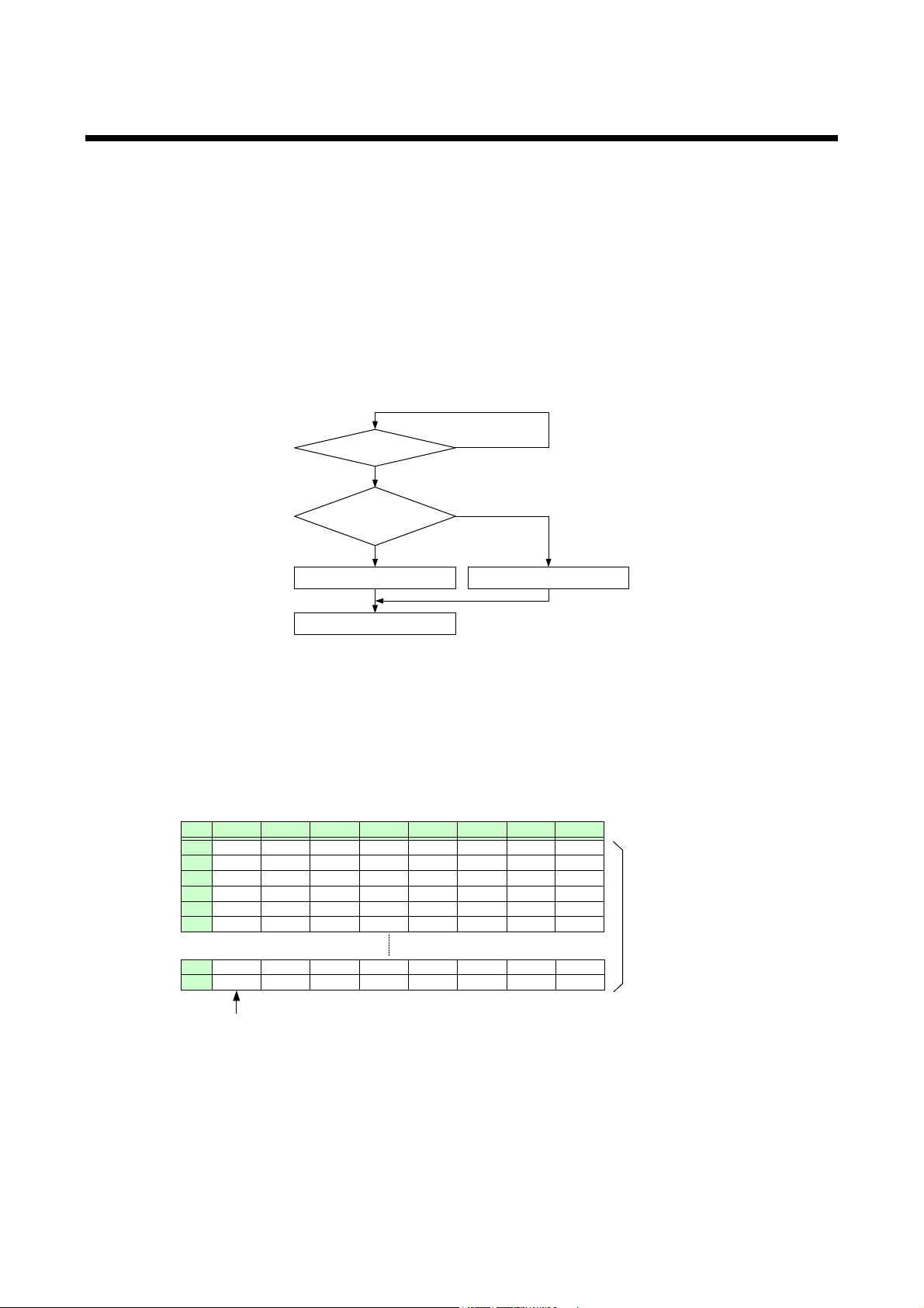
MSD-701UHD / 702UHD / 801UHD/ 802UHD User’s Guide
Was input signal
changed?
NO
YES
Was the signal
input before?
YES
NO
Loads prio r settings Initial izes input timing
Output video with new s et tings
1
2
3
4
IN1
1080i
720p
480i
XGA
5
6
50
49
SXGA
UXGA
VGA
1080p
IN2
1080i
480i
IN3
UXGA
WX GA
SXGA+
IN4
UXGA
VGA
IN5
WX GA
SVGA
IN6
NTSC
XGA
IN7
NTSC
WX GA
If inp ut da ta stor age ex ceed s 50 memory l ocati ons, the new memory entries will replace the earliest entries.
IN8
1080p
WX GA
Th e M S D retai ns
data for up to 50
device s f or eac h
inp ut conn ector.
9.2 Input Signal Automatic Detection
The MSD continuously m onitors its input signals. If a particular signal has previously been c onnec ted to the
MSD’s input, the output signal will be presented in the same f ormat as it was during the most recent session.
If an input signal does not match any signal previously presented to the MSD, only the input timing settings
are automatically negotiated. Other setti ngs are not aff ec ted. The output image size and format settings can
be adjusted if requi r ed.
【See: 9.4 Setting position, size, and masking】
【See: 9.5 Quality setting】
【See: 9.6.7 Fixing settings for each input signal】
【See: 9.7 Setting input timing】
[Fig. 9.3] How signals are recognized
The MSD retains data for up to 50 input devices for each input connector. The data is used to determine if a
signal has been presented to that connector previously by a particular device. The input signal have been
input before or not. If input data storage exc eeds 50 memor y l oc ations, the oldest data that have not been
input recentl y will be deleted, instead.
[Fig. 9.4] Memory table per channel
45
Page 46
MSD-701UHD / 702UHD / 801UHD/ 802UHD User’s Guide
Setting
Item
Setting position, size, and
Aspect ratio, Aspect ratio control, Overscan,
Black level
Automatic measurement of start position, Tracking
Audio setti ng
Input level, Lip sync
The following attributes are saved for each input signal.
[Table 9.1] Attributes saved for each inpu t signal
masking
Quality setting Sharpness, Brightness, Contrast, HUE, Saturation,
Input setti ngs Anal og input signal parameters
Setting input timing The total number of horizontal dots, Start posit ion, Active area,
Display position, Display size, Masking
9.3 Channel switching mode
Menu Top→SWITCHING MODE
Setting value V&A [Default], VIDEO, AUDIO
You can switch the channel switc hing mode.
46
Page 47

MSD-701UHD / 702UHD / 801UHD/ 802UHD User’s Guide
AUTO-B
1080i@50
(1920x1080)
WXGA+@60
(1440x900)
2160p@50(4096)
(4096x2160)
(1280x720)
WXGA@60
(1366x768)
2160p@25(4096)
(4096x2160)
576p@50
(720x576)
SXGA@60
(1280x1024)
2160p@50
(3840x2160)
(720x480)
WXGA@60
(1280x768)
2160p@25
(3840x2160)
WQHD@60
(2560x1440)
SVGA@60
(800x600)
1080p@60
(1920x1080)
WUXGA@60
(1920x1200)
1080p@50
(1920x1080)
WSXGA+@60
(1680x1050)
9.4 Setting position, size, and masking
Position, size, and masking attributes can be set f or both the input ports and output port s of the MSD.
Normally, it is preferable to set them for the input ports. If edges are cut off due to enlar ged display area by
the sink device side or if it is desired to modify the displayed area for all i nputs at once, set the desired
attributes for the output ports.
9.4.1 Output resolution
Menu Top→OUTPUT TIMING →RESOLUTION
Setting for Each output channel (Common to OUTA / OUTB)
Setting values
・AUTO-A [Default] ・[email protected] (1920x1080) ・WXGA++@60 (1600x900)
・
・2160p@60(4096) (4096x2160) ・720p@60 (1280x720) ・SXGA+@60 (1400x1050)
・
・2160p@30(4096) (4096x2160) ・720p@50 (1280x720) ・WXGA@60 (1360x768)
・
・2160p@24(4096) (4096x2160) ・576i@50 (720x576) ・Quad-VGA@60 (1280x960)
・2160p@60 (3840x2160) ・[email protected] (720x480) ・WXGA@60 (1280x800)
・
・2160p@30 (3840x2160) ・WQXGA@60 (2560x1600) ・XGA@60 (1024x768)
・
・2160p@24 (3840x2160) ・QWXGA@60 (2048x1152) ・VGA@60 (640x480)
・
・[email protected] (1920x1080) ・VESAHD@60 (1920x1080)
・
・1080i@60 (1920x1080) ・UXGA@60 (1600x1200)
Normally, the optimal resolution will be select ed automatically if you set this menu t o “AUTO”.
Numbers following “@” represent the vertical synchronous frequency.
480i / 480p / 576i / 576p / 720p / 1080i / 1080p / 2160p are timing formats relating to the CEA-861E standard.
Others are timing formats meeting either the VESA DMT standard or the VESA CVT standard. VESAHD@60,
WUXGA@60, QWXGA@60, WQHD@60, and WQXGA@60 are output formats that incorporate Reduced
Blanking.
The maximum format of OUTB (HDB aseT output connector) is 2160p@30. If 2160p@50 or 2160p@60 is
selected, video signals cannot be output from OUTB.
If ”AUTO-A” or “AUTO-B” is selected, the maximum output resolution format is set to 2160p@30 automatically.
If you want to output video at 2160p@50 or 2160p@60 from OUTA (HDMI output connector), change the
setting to 2160p@50 or 2160p@60. In this case, video cannot be output from OUTB (HDBaseT output
connector).
・
・
・
・
・
・
・
・
・
・
・
・
47
Page 48
MSD-701UHD / 702UHD / 801UHD/ 802UHD User’s Guide
■
[OUT1 RESOLUTION]
AUTO(1080p59.94)
[OUT1 RESOLUTION]
AUTO(1080p59.94)*
Outputting at optimal resolution
EDID cannot be loaded or optimal
resolution cannot be output
”AUTO-A” and “AUTO-B”:
“AUTO-A” (OUTA, HDMI output connec tor), “AUTO-B” (OUTB, HDBaseT output connector):
Automatically selects the optimal output resolution format depending on the EDID of the connect ed si nk
device. The optimal format is then provided to the connected sink device via the MSD’s output connector. The
actual output r esol ution is displayed in parentheses. In case EDID cannot be obtained from the sink dev ic e,
the resoluti on format that was last used is selected. This condition is indicat ed by an asterisk “*” to the right
side of the format data.
If the EDID of the connect ed si nk device is higher than 2160p@30, an asteri sk “*” is indicated to the right side
of the format data.
48
Page 49
MSD-701UHD / 702UHD / 801UHD/ 802UHD User’s Guide
9.4.2 Aspect ratio for sink device
Menu Top→OUTPUT TIMING→MONITOR ASPECT
Setting for Each output channel (Common to OUTA / OUTB)
Setting value
・RESOLUTION [Default] ・16:10 ・5:3 ・4:3
・256:135 ・16:9 ・5:4
You can set the aspect ratio of t he c onnec ted sink device.
If you select “RESOLUTION,” the aspect ratio of the output r esol ution will be applied. If aspect r atios of the
target sink devic e and the output resolution ar e diff er ent from each other, you can select an aspect r atio for
the sink device of: “4:3,” “5:4,” “5:3,” “16:9, ” “16:10,” and “256:135” (4096x2160).
【See: 9.4.1 Output resolution】
9.4.3 Aspect ratio
Menu Top→OUTPUT TIMING→INPUT ASPECT
Setting for Each input channel, each input signal
Setting value
・AUTO-1 [Default] ・4:3 ・14:9 S IDE PANEL
・AUTO-2 ・16:9 LETTER BOX ・FULL
・16:9 ・14:9 LETTER BOX ・THROUGH
・14:9 ・4:3 SIDE PANEL
You can set the aspect ratio f or each video input.
If you select “AUTO-1” or “AUTO-2,” the aspect ratio is restored automatically to the original ratio according to
the settings of si nk dev ic e aspect r atio and the MSD’s aspect ratio control.
“AUTO-1” and “AUTO-2” work differently only when letter box signals are pr esented t o the input. “AUTO-1”
processes them as 16:9 or 14:9 video signals, while “AUTO-2” sets them as 4:3.
Normally, no problem occurs if you set the aspect ratio to “AUTO-1”, but some DVD players and other devices
display subtitles or setup menus in t he un-displayed area. I n such case, set the aspect to “AUTO-2” to display
the entir e area of the video signals.
【See: 9.4.2 Aspect ratio for sink device】
【See: 9.4.4 Aspect ratio control】
Setting options of “16:9”, “14:9”, “4:3”, ”16:9 / 14:9 LETTER BOX”, and ”4:3 / 14:9 SIDE PANEL” are
accessible only when TV signals are input. When PC signals are input, the aspect ratio will be r estor ed
automatic ally ac c or ding to t he aspect ratio of the input signal regardless of the
settings:“AUTO-1”, ”AUTO-2”, ”16:9”, ”14:9”, ”4:3”, “16:9/14:9 LETTER BOX”, and ”4:3/14:9 SIDE PANEL”.
“FULL”: video signals are displayed always in full screen mode regardless of input video signal and settings of
“9.4.2 Aspect rati o for sink device” and “9.4.4 Aspect ratio control”.
“THROUGH”: video signals are displayed always in pixel 1:1 regardless of settings of “9.4.2 Aspect ratio for
sink device” and ”9.4.4 Aspect ratio control”.
49
Page 50
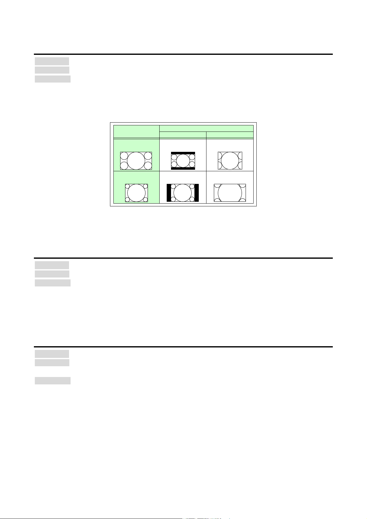
MSD-701UHD / 702UHD / 801UHD/ 802UHD User’s Guide
Input signal
16:9 input video is output to
a 4:3 sink device.
L-BOX/S-PANEL
Letter box
S-CUT/TB-CUT
Side panel
Output signal
4:3 input video is output to a
16:9 sink device.
Side cut
Top/bottom cut
9.4.4 Aspect ratio control
Menu Top→OUTPUT TIMING→ASPECT PROCESS
Setting for Each input channel, each input signal
Setting value L-BOX/S-PANEL : letter box/side panel [Default]
S-CUT/TB-CUT : Side cut/t op bott om c ut
Below is a visual description of restoring aspect ratio:
9.4.5 Overscan
Menu Top→OUTPUT TIMING→INPUT OVER SCAN
Setting for Each input channel, each input signal
Setting value 100% to 115%
You can create an enlarged display of input video.
9.4.6 Display position
Menu Top→OUTPUT TIMING→INPUT POSITION (input side) / OUTPUT POSITION (output side)
Setting for Input side : Each input channel, each input signal
Setting value
Input side:
Output side:
You can set the position where input video is displayed.
Note:
If the resolutions of each output are not the same, the resoluti on of OUT1 will be the standard.
50
[Fig. 9.5] Restoring aspect ratio
[Default] NTSC / PAL / SDTV: 105 %, H DTV / PC: 100 %
Output side : Each output c hannel
Horizontal position (-Horizontal input size to +Horizontal out put resol ution [Default] 0)
Vertical position (-Vertical input size to +Vertical output resolution [Default] 0)
Horizontal position (-Hori z ontal output size to +Horizontal output resol ution [Default] 0)
Vertical position (-Vertical output size to +Vertical output resoluti on [Default] 0)
Page 51

MSD-701UHD / 702UHD / 801UHD/ 802UHD User’s Guide
9.4.7 Display size
Menu Top→OUTPUT TIMING→INPUT SIZE (input side) / OUTPUT SI ZE (output side)
Setting for Input side : Each input channel, each input signal
Output side : Each output c hannel (Common to OUTA / OUTB)
Setting value
Input side: Horizontal size (Horizontal output resolution ÷ 4 to Horizontal output resolution x 4
[Default] Horizontal output resolution)
Vertical size (Vertic al output resolution ÷ 4 to Vertical output resolution x 4
[Default] Vertical output resolution)
Output side: Horizontal size (Horizontal output resolution ÷ 4 to Horizontal output resolution x 4
[Default] Horizontal output resolution)
Vertical size (Vertical output resolution ÷ 4 to Vertical output resolution x 4
[Default] Vertical output resolution)
You can set the display size of input video.
The vi deo size is scaled based on the upper left quadrant of the input video.
If you set “LINK” to ”ON”, only settings of ”H”(Horizontal) can be set and “V” is set automatically while retaining
the current aspect r atio.
【See: 9.4.6 Display position】
Notes:
・If the resolutions for each output are not the sam e, t he output r esol ution of OUT1 will be the standard.
・Numbers following “/” show the output resolut ion.
51
Page 52
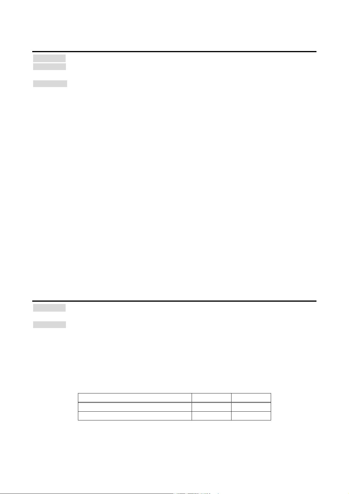
MSD-701UHD / 702UHD / 801UHD/ 802UHD User’s Guide
Items to be initialized
Input side
Output side
Aspect ratio, ovescan
Initialized ‐
Display position, display size, masking
Initialized
Initialized
9.4.8 Masking
Menu Top→OUTPUT TIMING→INPUT MASKING (Input side) / OUTPUT MASKING (Output side)
Setting for Input side : Each input channel, each input signal
Output side : Each output channel (Common to OUTA / OUTB)
Setting value
Input side: Left side masking (Horizontal input position to Right side masking
[Default] 0)
Right side masking (Left side masking to Horizontal input position + Horizontal input size
[Default] Horizontal input size)
Top side masking (Vertical input position to Bottom side masking
[Default] 0)
Bottom side masking (Top side m asking to Vertical input positi on + Vertical input size
[Default] Vertical input size)
Output side: Left side masking (Horizontal output position (0 or mor e) to Right side masking
[Default] 0)
Right side masking (Left side masking to Horizontal output position + Horizontal output size
(Horizontal output resolution or less)
[Default] Horiz ontal output resolution)
Top side masking (Vertical output posi tion (0 or more) to Bottom side masking
[Default] 0)
Bottom side masking (Top side masking to Vertical output position + Vertical output size
(Vertical output resolution or less)
[Default] Vertical out put resolution)
You can set the masking of video inputs to hide unnecessary portions of t he displ ay ed area (top/bottom and
right/left).
9.4.9 Automatic sizing
Menu Top→OUTPUT TIMING→INPUT AUTO SIZING (Input side) /
OUTPUT AUTO SIZING (Output side)
Setting for Input side : Each input c hannel, each input signal
Output side : Each output c hannel (Common to OUTA / OUTB)
This function adjusts output signal optimally, and as a result, the following settings will be initialized
automatically.
A long buzzer tone will sound when the init ialization is completed by pressing the MENU/SET key.
[Table 9.2] Items to be initialized
52
Page 53
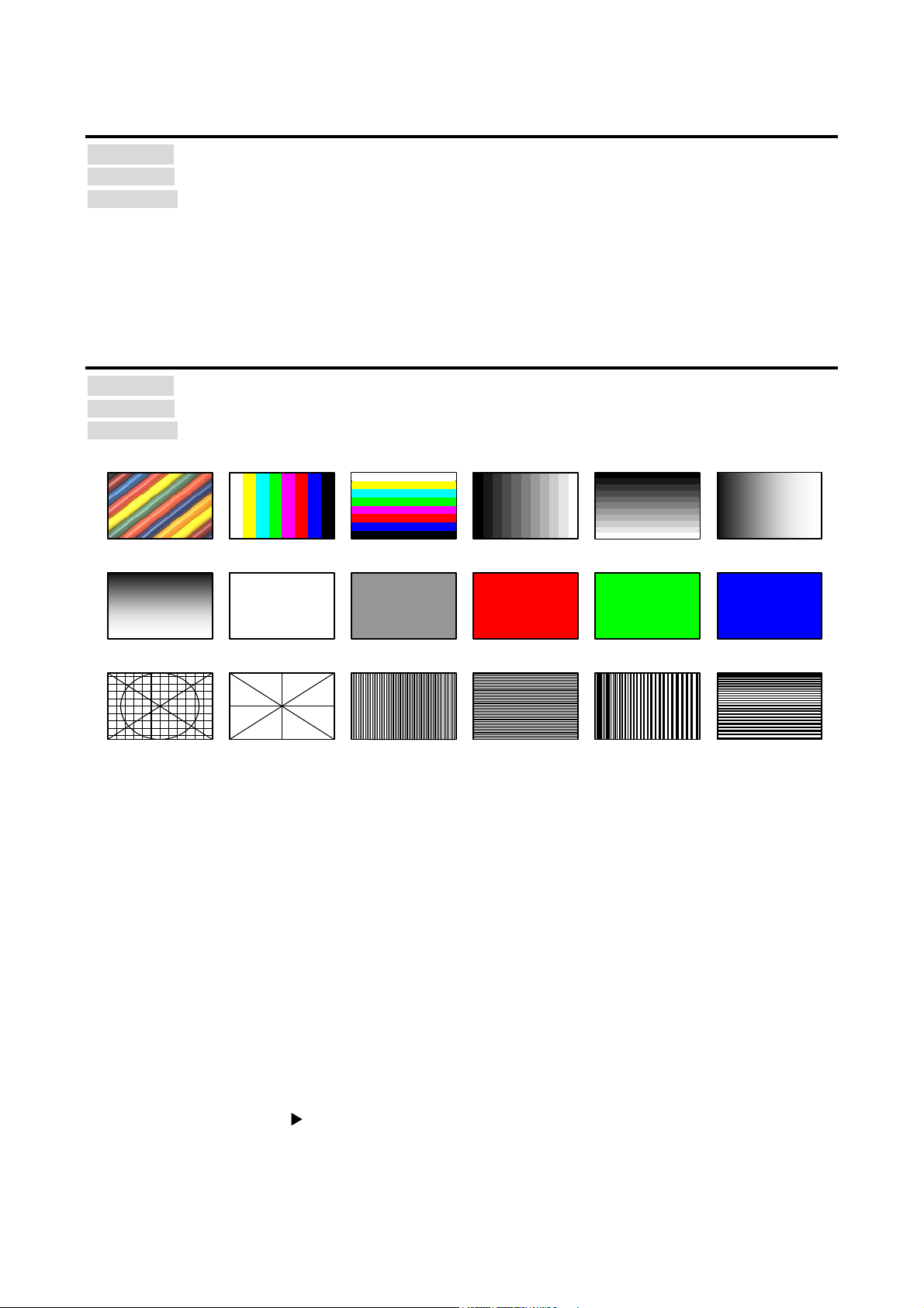
MSD-701UHD / 702UHD / 801UHD/ 802UHD User’s Guide
VERTICAL RAMP
50% WHITE
RASTER
V-COLOR BAR
V-GR A Y SCALE
RED RASTER
GREE N RASTER
BLUE RASTER
100% WHITE
RASTER
CROSS HATCH
OUTP UT FRA ME
VERTICAL
STRIPE
HORIZONTAL
STRIPE
VERTICAL
ZEBRA
H-COLOR BAR
H-GR A Y SCALE
HORIZONTAL
RAMP
HORIZONTAL
ZEBRA
OFF [Default]
(Normal video output)
9.4.10 Background color
Menu Top→OUTPUT TIMING→BACKGROUND COLOR
Setting for Each out put channel (Common to OUTA / OUTB)
Setting value R / G / B: 0 to 255 [Default] R / G / B: 0 (black)
You can set the background color of output video.
If you set “LINK” to ”ON”, only the setting for ”R” can be set, and “G” and “B” trac k the setting of “R”.
9.4.11 Test pattern
Menu Top→OUTPUT TIMING→TEST PAT TE RN
Setting for Each output channel (Common to OUTA / OUTB)
Setting value [Fig. 9.7] T est patt er n
You can activate the MS D’s i nternal test pattern generator and direct its signal to each output connector.
While activ e, the test patt er n will override any other signal t hat has been switc hed to that particular output
connector.
All settings of “9.5 Quality setting” will be invalid while a test pat tern is displayed.
“OUTPUT FR A ME”: Select this pattern if par t of im age is not displ ay ed on the sink device.
Settings of “9.4.6 Display position” and “9.4.7 Display size” in the output side will be adjusted in order to
display the test pattern on full screen.
For test patterns other than “OUTPUT FRAME”: video is output on full screen with the resolution set in “9.4.1
Output resolution” and the settings of ”9.4.6 Display position”, “9.4.7 Display size” and “9.4.8 Masking”
will be invalid.
You can use the arrow keys (
SCALE”, ”RAMP”, and ”ZEBRA” by using. The scroll speed can be set by 3 pixels per frame up to 30 pixels
per fram e with ▲ and ▼ keys. You can check the resi dual image (resoluti on of moving pic ture) by
displaying and scrolling the “ZEBRA” pattern.
[Fig. 9.6] Test pattern
▼
, ▲, ▼) to scroll through the available patt er ns “CO LOR BA R”, ”GRAY
53
Page 54
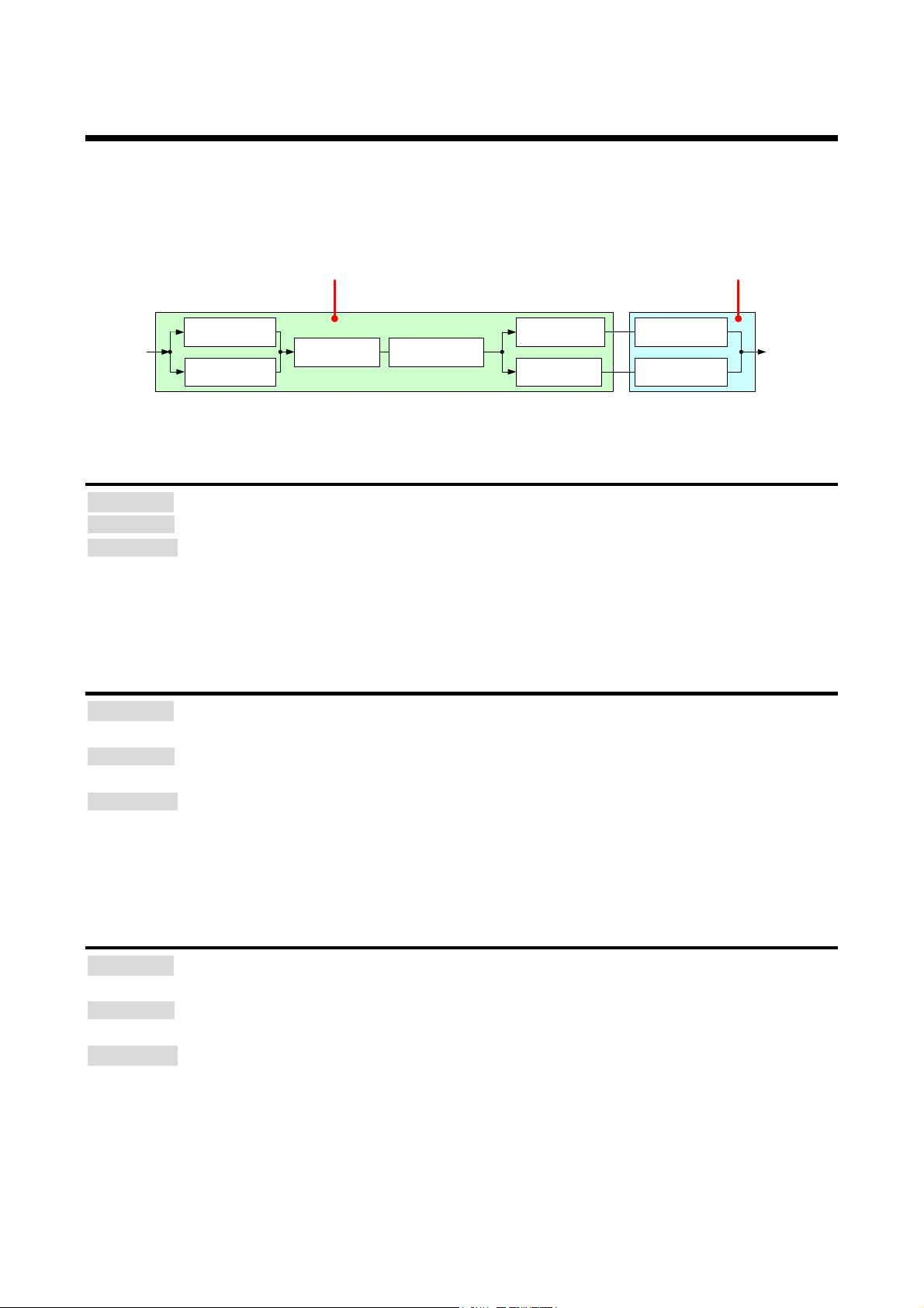
MSD-701UHD / 702UHD / 801UHD/ 802UHD User’s Guide
Output
signals
Input
signals
HUE
SETUP
SATURATION
CONTRAST
Setting for input channels Setting for output channels
SHARPNESS
BRIGHTNESS
BRIGHTNESS
CONTRAST
9.5 Quality settings
Setting items for input channels are for correcting color bias.
Image quality to be output can be set for each input side (input channels) and output side (output channels) as
follows.
[Fig. 9.7] Video correction
9.5.1 Sharpness
Menu Top→IMAGE EFFECT→INPUT SHARPNESS
Setting for Each input channel, each input signal
Setting value -5 to 15 [Default] 0
You can set the desired level of sharpness for each input signal .
9.5.2 Brightness
Menu Top→IMAGE EFFECT→INPUT BRIGHTNESS (Input side) /
OUTPUT BRIGHTNESS (Output side)
Setting for Input side : Each input c hannel, each input signal
Output side : Each output c hannel (Common to OUTA / OUTB)
Setting value 80% to 120% [Default] 100%
You can set the brightness level for each input/output signal.
9.5.3 Contrast
Menu Top→IMAGE EFFECT→INPUT CONTRAST (Input side) /
OUTPUT CONTRAST (Output side)
Setting for Input side : Each input c hannel, each input signal
Output side : Each output c hannel (Common to OUTA / OUTB)
Setting value R / G / B:0% to 200% [Default]: R / G / B: 100%
You can set the contrast of video im age.
If you set “LINK” to ”ON”, only the setting for ”R” can be set, and “G” and “B” trac k the setting of “R”.
54
Page 55
MSD-701UHD / 702UHD / 801UHD/ 802UHD User’s Guide
9.5.4 HUE
Menu Top→IMAGE EFFECT→INPUT HUE
Setting for Each input channel, each input signal
Setting value 0° to 359° [Default] 0°
You can set the color HUE for each input si gnal.
9.5.5 Saturation
Menu Top→IMAGE EFFECT→INPUT SATURATION
Setting for Each input channel, each input signal
Setting value 0% to 200% [Default] 100%
You can set the color saturation for each input signal.
9.5.6 Black level
Menu Top→IMAGE EFFECT→INPUT SETUP LEVEL
Setting for Each input channel, each input signal
Setting value -10.0% to 10.0% (by 0.5%) [Default] 0.0%
You can adjust the black lev el f or each input signal.
9.5.7 Gamma
Menu Top→IMAGE EFFECT→OUTPUT GAMMA
Setting for Each out put channel (Common to OUTA / OUTB)
Setting value 0.1 to 3.0 (by 0.1) [Default] 1.0
You can adjust the gamm a curve of each output signal.
55
Page 56
MSD-701UHD / 702UHD / 801UHD/ 802UHD User’s Guide
Gamma
-
Initialized
9.5.8 Default color
Menu Top→IMAGE EFFECT→IN DEFAULT COLOR (Input side) /
OUT DEFAULT COLOR (Output side)
Setting for Input side : Each input c hannel, each input signal
Output side : Each output c hannel (Common to OUTA / OUTB)
You can initialize settings of the following items.
A long buzzer tone will sound when the initializati on is completed by pressing the MENU/S ET k ey.
[Fig. 9.8] Items to be initialized
Items to be initialized Input side Output side
Brightness, contr ast Initialized Initialized
Sharpness, hue, saturation, black level Initialized ‐
56
Page 57
MSD-701UHD / 702UHD / 801UHD/ 802UHD User’s Guide
Changing EDID
ON
OFF
Requesting source device to
output video signals
Monitoring time
Hot plug
ON
OFF
Video signals from
source device
Changing EDID
Monitoring
time
ON
OFF
Monitoring
time
Monitoring
time
Video output timing of source device
Video signals from
source device
Requesting source device to output video signals
9.6 Input settings
9.6.1 No-signal input monitoring
Menu Top→INPUT SETTING→IN PU T V ID EO DETECT
Setting for Each input channel ( only digital input signal)
Setting value OFF, 2000ms to 15000ms (100 ms steps) [Default] 10000ms
If you change the EDID settings of the MSD or power the MSD off/on, the source device may not output a
video signal. Use this menu to set the monitoring time which is from when a source dev ic e stops outputting
signal to when the MSD requests the source dev ice to output video signal.
[Fig. 9.9] Monitoring absence of input [Fig. 9.10] Repeating reset
Note:
If you ar e usi ng the monitor power-saving or dual monitor features on your PC, se t this feature to “OFF”. This
will avoid unpredic table operation.
When using this feature, ensure that the “monitoring time” is set for a value greater than the amount of time
needed for the source to prov ide an output signal.
57
Page 58
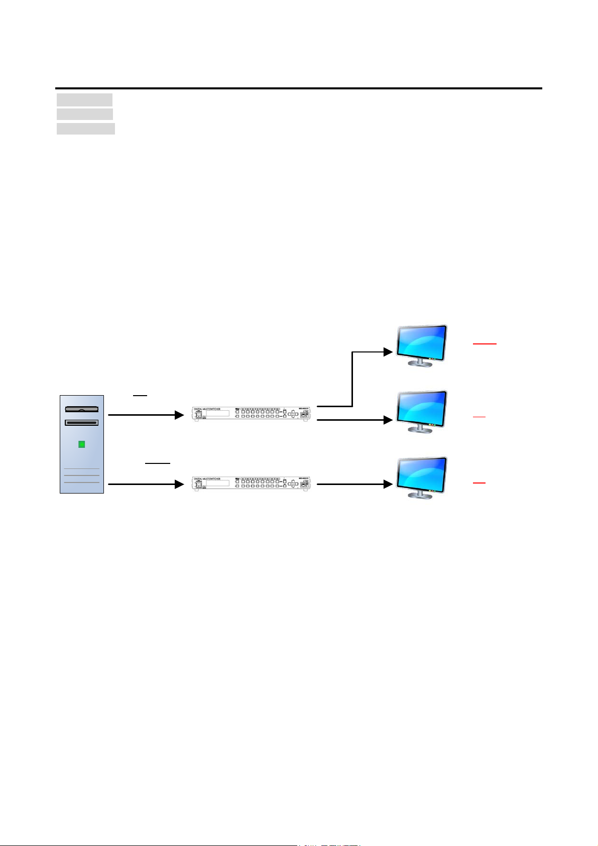
MSD-701UHD / 702UHD / 801UHD/ 802UHD User’s Guide
Video with copyright
protection
Video without
copyright protection
HDCP
supported PC
Video cannot be
displayed
HDCP-non-supported sink device
Video can be displayed
HDCP supported sink device
Video can be displayed
HDCP supported/non-supported sink device
MSD-802UHD
Input HDCP setting “HDCP2.2”
Input HDCP setting “DISABLE”
9.6.2 Input HDCP setting
Menu Top→INPUT SETTING→HDCP INPUT ENABLE
Setting for Each input channel ( only digital input signal)
Setting value
・HDCP 2.2 : Supports HDCP 2.2 and HDCP 1.4 [Default]: [IN1, IN2, IN8]
・HDCP 1.4 : Supports HDCP 1.4 [Default]: [IN3 to IN7]
・DISABLE : Not support HDCP
Some source devices negotiates with the connected device to determine if it supports HDCP encryption. After
this negotiation, the source device controls whether or not a signal m ay be sent to the devic e. This process
takes place with som e source device, even if the content being presented is not copyright protected. The
MSD is HDCP compli ant, if it is connected to a display device that does not support HDCP, video may not be
displayed. Under these circumstances and if the content is not protected, t he pr oblem c an be solved by
setting this menu to “DISABLE.”
【See: 9.6.5 Selecting signal of DVI input connector】
[Fig. 9.11] HDCP-supported a nd HDCP-non-suppo rted di spl ay devices
Notes:
・HDCP2.2 (stream type 0) contents can be displayed on sink devices supporting HDCP1.4.
・HDCP2.2 (stream type 1) contents can be displayed on sink devices supporting HDCP2.2 but cannot be
displayed on sink devic es suppor ting HDCP1.4.
58
Page 59

MSD-701UHD / 702UHD / 801UHD/ 802UHD User’s Guide
9.6.3 Analog input signal parameters
Menu Top→INPUT SETTING→ANALOG INPUT TYPE
Setting for Each input channel, each input signal (only analog input)
Setting value
・AUTO : Autom atic [Def ault] ・VIDEO AUTO : Video automatic
・RGB : Analog RGB ・VIDEO : Composite video
・YPbPr : Analog YPbPr ・Y/C : S video
You can set the signal type that is bei ng pr esented to the DVI-I input connector .
If you select “AUTO”, the type of input signals are detected automati c ally. In cases where the detecti on fails
and video is not output c or r ectly , set t he input type manually. With “AUTO”, the automatic detection of
S-Video may fail. If both com posi te video and S-Video are input at the same time, select “VIDEO AUTO”; if
only S-Video is input, sel ec t “Y /C”.
This menu is available only if an analog signals are present on input por ts 6 or 7.
【See: 9.6.5 Selecting signal of DVI input connector】
Note:
For video from a monochrome camera or VHS tape with in poor condition or the like, automatic detection may
fail. Under these circ um stanc es, select “VIDEO AUTO”, “VIDEO” or “Y/C”.
59
Page 60
MSD-701UHD / 702UHD / 801UHD/ 802UHD User’s Guide
・
・
・
9.6.4 Automatic detection of video input interruption
Menu Top→INPUT SETTING→INPUT OFF CHECK
Setting for Each input channel
Setting value ON [Default], OFF
The MSD can stop outputti ng v ideo im m ediately after input video signals are disconnected for a moment.
Use this feature to minimize switching artifacts produced by an external device connected to the MSD’s input
connector. The effect of thi s function is similar to switching the MSD’s input.
9.8.4 Window transaction effect
9.8.5 Window transaction speed
9.8.6 Wipe color
Notes:
・If you select “ON” and are using a video input (VHS tapes or the like) with a poor quality signal, it’s possible
that the output will flash on and off. This is due to sync signal distortion that can be interpreted as periods of
time without signal pr esence. In this case, set this menu to “OFF”.
・Even if you set this feature to “ON”, distorted video cannot be corrected completely when input video signals
are lost. Especially if you set “9.8.4 Window transaction effect” to an option other than “CUT”, noises or
black bars may be output at the time of fading out or wiping out.
9.6.5 Selecting signal of DVI input connector
Menu Top→INPUT SETTING→INPUT AD TYPE
Setting for Each input channel (only DVI i nput connector)
Setting value DIGITAL [Default], ANALOG
You can select either digital or analog formats.
9.6.6 HDBaseT input long reach mode
Menu Top→INPUT SETTING→LONG REACH MODE
Setting for HDBaseT input channel
Setting value
・OFF : Long reach mode disabled. Up to 328 ft. (100 m) [Def ault]
・ON : Long reach mode enabled. Up to 492 ft. (150 m)
You can enable / disable long r eac h m ode for HDBaseT input.
In long reach mode, up to 1080p (24 bit)/ dot cl oc k 148 MHz is supported when using with IDK’s HDbaseT
product. Set the MSD’s EDID t o 1080p or l ess or set the connec ted device’s output to a supported signal
format.
【See: 9.10 EDID (Extended Display Identification Data)】
60
Page 61
MSD-701UHD / 702UHD / 801UHD/ 802UHD User’s Guide
(IN1 to IN8*)
(IN6 and IN7*)
ASPECT
Can be set
Can be set
ANALOG TYPE
Cannot be set
Can be set
AUDIO LEVEL
Can be set
Cannot be set
9.6.7 Fixing settings for each input signal
Menu Top→INPUT SETTING→IN PU T TA BL E FIXED
Setting for Each input channel
Setting value
Setting mode:
・SELECTED : Sets for each item [Default]
・ALL FIXED : Does not load settings saved for each input signal but fixes the current settings
Individual setting (if “SELECTED” is selected for the setting mode):
・ASPECT : OFF [Default], ON(FIXED) 【See: 9.4.3 Aspect ratio】
・ANALOG TYPE : O FF, ON(FIXED) [Default] 【See: 9.6.3 Analog input signal par am eters】
・AUDIO LEVEL : OFF, ON(FIXED) [Default] 【See: 9.9.4 Input level】
The MSD continuously monitors the input signals. If a particular input signal that has been presented to the
MSD before is input again, the MSD will output the signal at the same size and quality as its previ ous use.
【See: 9.2 Input Signal Automatic Detection】
You can select the setting saved for each signal or the current sett ing.
“ALL FIXED”: Does not load all settings saved for each input signal but outputs the video with the cur r ent
setting.
“SELECTED”: Aspect ratio, analog input signal type and audio input level can be set indiv idually. For setting
items other than settings in [Table 9.1], setti ngs saved for eac h input signal are used.
“OFF”: Settings saved for each input signal are used to form at t he video output.
“ON (FIXED)”: Current settings are used to format the video output.
[Table 9.3] Individual settings for each digital or analog signal
Individual setting
*IN6 and IN7: Digital and analog input signals can be accommodated.
For signal election, see “9.6.5 Selecting signal of DVI input connector”.
Digital signal
Analog signal
61
Page 62
MSD-701UHD / 702UHD / 801UHD/ 802UHD User’s Guide
Analog input
Digital input
The total number of horiz ontal dots
Partly 1, Partly 2
Partly 2
Start positi on
Can be set
Can be set
Active area
Can be set
Can be set
Automatic measurement of start
Can be set
Cannot be set
Tracking
Partly 1
Cannot be set
9.7 Setting input timing
You can set the timing param eters for analog signal inputs.
The MSD loads the optimal t able from its embedded library of tables and adjusts the input timing
automatic ally , you typically will not need to change settings i n this menu. However, if signal s which are not
registered in the MSD tables are input or if part of the video image is cut off while relying on the standard table
registered in the MS D, you m ay optimi z e the input timing parameters manually.
For digital inputs, you typic ally do not need to manually set timing paramet er s, but if part of the video image is
cut off, you may make fine adjustments as required.
[Table 9.4] Settable items
Function
Automatic measurement Partly 1 Cannot be set
position
Automatic setti ng of input timing Can be set Cannot be set
Loading devic e data Partly 3 Can be set
Registering device data Partly 1 Cannot be set
Partly 1: can be set onl y if analog RGB / analog YPbPr signals are input.
Partly 2: only di spl ay ed if analog video signals are input or for digital input.
Partly 3: can be set only if the device data of input signals are registered in the MSD.
62
Page 63
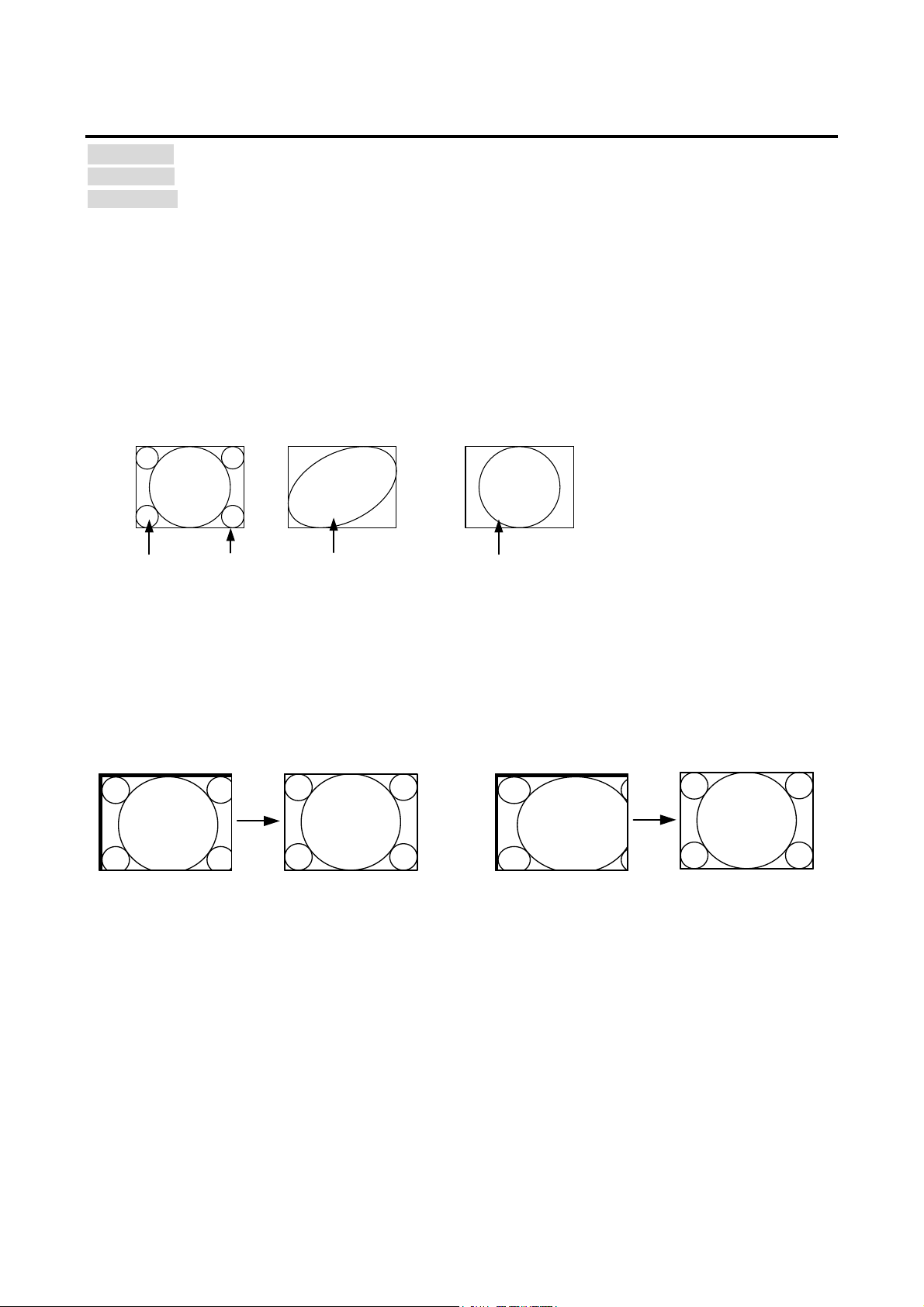
MSD-701UHD / 702UHD / 801UHD/ 802UHD User’s Guide
Input video
Valid display
area
Input video
Input video
●Cannot be measured:
- R i ght an d l ef t side s of input video do not touc h t h e c i rcumsc ri be d
rectangle.
- Bri ght ness of inp ut vi deo is 24% or less.
●Can be measure d:
- Input video c onta ct s the circu m scr i bed rectan gl e .
- Bri ght ness of inp ut vi deo is 25% or m ore.
If the input video is not recognized correctly
like above, it can adjust by executing
“NORMAL MODE” automatic input
measurement.
If the setting of active area is not correct
and it cannot adjust only by starting
position, the active area is also adjusted by
executing automatic input measurement.
9.7.1 Automatic measurement
Menu Top→INPUT TIMING →AU T O SETU P
Setting for Each input channel, each input signal (only analog input signal)
Setting value
・NORMAL MODE [Default] ・4:3 ・5:3 ・16:10
・NEXT ASPECT ・5:4 ・16:9
Analog RGB/analog YPbPr input video is measured to set ”9.7.2 The total num be r of horizonta l
dots”, ”9.7.3 Start positi on”, ”9.7.4 Active area” , and “9.7.9 Tracking“ automatically.
[Fig. 9.12] Conditions of automatic measurement
By selecting “NORMAL MODE”, the MSD performs automatic measurement of the start posi tion and active
area. If edges of video ar e not displayed correctly, use thi s mode t o set the start position and active area
automatically.
[Fig. 9.13] Automatic measurement by “NORMAL MODE”
63
Page 64
MSD-701UHD / 702UHD / 801UHD/ 802UHD User’s Guide
[IN7 AUTO SETUP]
1024x 768 60.00Hz
2 sec.
5 sec.
2 sec.
5 sec.
Automatic measurement starts
(NEXT ASPEC T)
Automatic measurement starts
(NOR MA L MODE )
Pressing and holding the key
If the total number of hori z ontal dots is not correct, the aspect rati o is not m atched even though automatic
measurement i s set to “NORMAL MODE” . I n this case, select “NEXT ASPECT” (Auto measurement taking
into account aspect r atio) for the measurement f unction. If the aspect ratio of the input si gnal is known, you
can directly specify the aspect ratio to correctly perform automatic m easurement.
If the input si gnals are not registered in the MSD, it is recommended to use this function.
If there is no input signal on the input channel it shows “NOT AVAILABLE NOW” on the front VFD screen.
Press the “MENU/SET” key to perform automatic measurement.
Note:
In case the aspect ratio does not match or video is displayed on the position far from the correct position, set
the input timing in, “9.7.2 The total number of horizontal dots”, “9.7.3 Start position”, and “9.7.4 Active
area”.
■ Op erat io n f rom front keys
You can execute the automatic measurement in “NORMAL MODE” by pressing an IN6 or IN7 key (analog
input only) for 2 seconds or longer. If you want to execute the automatic measurement in “NEXT ASPECT”,
press the same key for 5 seconds or longer.
【See: 9.6.5 Selecting si gnal of DVI input connector】
64
[Fig. 9.14] Automatic measurement using front key
Page 65
MSD-701UHD / 702UHD / 801UHD/ 802UHD User’s Guide
(The total number of hori z ontal dots-Horizontal active area or less)
Vertical start posi tion
10LINE to 2048LINE
9.7.2 The total number of horizontal dots
Menu Top→INPUT TIMING →H TOTAL DOTS
Setting for Each input channel, each input si gnal (only analog input signal)
Setting value 400DOT to 4125DOT [ Default] varies depending on the input signal
You can set the total number of hori z ontal dots of analog RGB/analog YPbPr i nput video.
The settable values vary depending on the input signal. If interlace signal are input, the sampling clock
(Horizontal synchronized frequency x the total number of horizontal dots) must be within 13 MHz to 81 MHz.
If non-interlace si gnal are input, the sampling cl oc k must be withi n 13 M Hz to 162 MHz.
If other signals are input, the total number onl y can be display ed but not set.
If there is no input signal on the input channel it shows “NOT AVAILABLE NOW” on the front VFD screen.
9.7.3 Start position
Menu Top→INPUT TIMING →H START (Horizontal) / V START (Vertical)
Setting for Each input channel, each input si gnal
Setting value [Table 9.5] Settings of start position
[Table 9.5] Settings of start position
Function Setting value
Horizontal start position 64DOT to 2900DOT
(The total number of v ertic al lines-Vertical active area or less)
[Default] vari es dependi ng on the input signal.
You can set the horizontal/vertical starti ng posi tion.
Setting val ue must be as foll ows. If the set value exceeds the value, the start ing position will be set the limit
value within the settable range automatically.
Horizontal : The total number of horizont al dots > Horizontal active area > Horiz ontal starting position
Vertical : The total number of ver tical lines > Vertical active ar ea > V ertic al star ting position
If 4K video signals are i nput, only the display start position will be displ ay ed; the value cannot be set.
If there is no input signal on the input channel it shows “NOT AVAILABLE NOW” on the front VFD screen.
65
Page 66
MSD-701UHD / 702UHD / 801UHD/ 802UHD User’s Guide
9.7.4 Active area
Menu Top→INPUT TIMING→H DISPLAY (Horizontal) / V DISPLAY (Vertical)
Setting for Each input channel, each input si gnal
Setting value [Table 9.6] Settings of active area
[Table 9.6] Settings of active area
Function Setting value
Horizontal active area 64DOT to 2900DOT (The total number of horizont al dots-64 or less)
Vertical activ e ar ea 10LINE to 2048LINE (The t otal number of ver tical lines-10 or less)
[Default] v ari es dependi ng on the input signal.
You can set the horizontal/vertical active area of input video.
The horizontal setting value must be [The total number of horizontal dots > Hori z ontal active area]. If the set
value exceeds the limit value by changing the total number of horizontal dots, the horizontal active area will be
set to the limit value within the set range automatically.
If 4K video signals are i nput, only the active area will be displayed; the value cannot be set.
If there is no input signal on the input channel it shows “NOT AVAILABLE NOW” on the front VFD screen.
66
Page 67
MSD-701UHD / 702UHD / 801UHD/ 802UHD User’s Guide
9.7.5 Automatic measurement of start position
Menu Top→INPUT TIMING→A U T O S TART POS
Setting for Each input channel, each input si gnal (only analog input signal)
Setting value ALL OF F : not measuring all inputs from the input automatically
OFF : not measuring the current input signal automatically
ON : measuring the current input signal automatically [Default]
The MSD monitors conti nuousl y the upper left of analog input video si gnal and it automatically matc hes the
upper left of the input v ideo and the upper left of the screen.
Notes:
・For motion images, some content may not be di spl ayed on the full screen, and the display position may be
moved every time the setti ng of t he automatic measurement is appli ed. I n such a case, set this menu to
“OFF”. As “OFF” and “ON” are saved for each input signal, it can be set according to t he input signal. If you
do not want to perform this function for all resolution, select “ALL OFF”.
・Only the start position is set by automatic measurement of this menu. If “9.7.2 The total num be r of
horizo nta l dots” and “9.7.4 Active area” do not match, the lower right m ay be cut off or black out may be
output. In this case, adj ust the whole screen by following “9.7.1 Automatic measurement”. A s the set
value must not exceed the v alue set in “9.7.3 Start position”, some input videos are displayed with
blackout at the left or top si de.
・This menu is valid only if “[Fig. 9.13] Conditions of automatic measurement” is satisfactory.
・Even if you set this menu to “ON”, the manual setting will be applied and the automatic measurement is not
executed if you set any of t he following menus: “9.7.2 The total number of horizontal dots”, “9.7.3 Start
position”, and “9.7.4 Active area”. If you set “9.7.9 Tracking”, the manual setting is applied, and tracing is
not set automatically when the automatic measurem ent is executed. When you execute “9.7.1 Automatic
measurement”, setti ngs of this menu will be valid again.
9.7.6 Automatic setting of input timing
Menu Top→INPUT TIMING→UNKNOWN TIMING
Setting for None
Setting value A UTO SET UP ON [Default], AUTO SETUP OFF
The MSD loads the optimal t able from the built- in tables and sets the input timing automatically. However, if
unregistered signal s are input, the input timing must be set. By setting this menu to “AUTO SETUP ON”,
“9.7.1 Automatic measurement” is executed and the input timing is set automatically if signal that cannot be
detected by the MSD are input f or the fi r st time.
Note:
If automatic measurement finds inconsistency of aspect ratio, please perform “9.7.1 Automatic
measurement” manually or set the input timing in “9.7.2 The total number of horizontal dots”, “9.7.3 Start
position” and/or “9.7.4 Active area”.
67
Page 68
MSD-701UHD / 702UHD / 801UHD/ 802UHD User’s Guide
You want to set the input timing again.
Digital
The value that is automatically detected by the MSD will be set.
9.7.7 Loading device data
Menu Top→INPUT TIMING →LOAD
Setting for Each input channel, each input si gnal
Device data whose input timing is registered can be loaded according to the input signal.
The setting of this menu is not updat ed until the MENU/SET key is pressed. Make sure to press the
MENU/SET key to update the setti ng.
If there is no input signal on the input channel it shows “NOT AVAILABLE NOW” on the front VFD screen.
[Table 9.7] Items to be loaded
Input signal Item
Analog Registered device data will be loaded.
Use this menu in the following cases:
• Sever al dev ic e data with the same frequency of synchronou s signal and different input
timings is regi ster ed.
•
Use this menu to restore the input timing to the original value.
9.7.8 Registering device data
Menu Top→INPUT TIMING →SAVE
Setting for Each input channel, eac h input signal (only analog input signal)
Setting value No. 1 to No.99
You can save up to 99 analog RBG/analog Y P bP r input timing settings.
The device data can be named up to 14 characters using ASCII code 20 to 7D. The device table nam e is
optional. If a dev ic e table name is not registered and press MENU/SET key without device table name, the
input resoluti on is registered as the device table name automatically. If a device table name is already
registered and press MENU/ S E T key without device table name, the input timing is saved to the device table
name without changi ng the device table name.
From the next time, when the same signal is input to other channel, video will be displayed with the register ed
timing.
The setting of this menu is not updat ed until the MENU/SET key is pressed. Make sure to press the
MENU/SET key to update the setti ng.
If there is no input signal on the input channel it shows “NOT AVAILABLE NOW” on the front VFD screen.
9.7.9 Tracking
Menu Top→INPUT TIMING→TRACKING
Setting for Each input channel, each input si gnal (only analog input signal)
Setting value 0 to 63 [Default]: 0
You can adjust the tracki ng of analog RGB/analog YPbPr input video.
If there is no input signal on the input channel it shows “NOT AVAILABLE NOW” on the front VFD screen.
68
Page 69
MSD-701UHD / 702UHD / 801UHD/ 802UHD User’s Guide
9.8 Output settings
9.8.1 Output mode
Menu Top→OUTPUT SETTING→OUTPUT MODE
Setting for Each out put channel (Each OUTA / OUTB)
Setting value
・HDMI YCbCr 4:4:4 MODE [Default] ・HDMI RGB MODE
・HDMI YCbCr 4:2:2 MODE ・DVI MODE
・HDMI YCbCr 4:2:0 MODE *only OUTA
You can select an out put signal mode and color space of the output video. The MS D output s selected mode,
however, if the connect ed si nk dev ic e has optimal output mode and color space, the MSD outputs optimal
output mode signal for the connec ted sink device.
“HDMI YCbCr 4:2:0 MODE”: YCbCr 4:2:0 has priority if the resolution is 4K@60 / 59.94 / 50 while YCbCr
4:4:4 has priorit y for other resolutions.
Higher priority HDMI YCbCr 4:4:4 MODE
HDMI YCbCr 4:2:2 MODE
HDMI YCbCr 4:2:0 MODE
HDMI RGB MODE
Lower priority DVI MODE
Notes:
・If “DVI MODE” is selected and the output resolution is 2160p@30 or lower, the MSD outputs DVI signals.
For other resolutions, it out puts signals at the appropriate mode of the connected sink devic e.
・Only TV resolutions (480i, 576i, 720p, 1080i, 1080p, and 2160p) can be output in ”HDMI YCbCr 4:4:4 MODE”
or “HDMI YCbCr 4:2:2 MODE”. PC resolutions are output in “HDMI RGB MODE” or “DVI MODE”.
・Since OUTB (HDBaseT output connector) does not support Y CbCr 4:2:0, ”HDMI YCbCr 4:2:0 MODE”
cannot be selected.
9.8.2 Synchronous signal output with no input video
Menu Top→OUTPUT SETTING→SYNC OUTPUT
Setting for Each output channel (Common to OUTA / OUTB)
Setting value ON [Default], OFF
You can set whether synchronou s signal s are out put when no video signals are input from the selected input,
or when “OFF” is selected for the input. If you set this menu to “ON”, you can prevent the sink device from
being switched to the standby m ode.
69
Page 70
MSD-701UHD / 702UHD / 801UHD/ 802UHD User’s Guide
9.8.3 Output video with no input video
Menu Top→OUTPUT SETTING→VID EO OUT P U T
Setting for Each out put channel (Common to OUTA / OUTB)
Setting value
・BLUE [Default] ・BACKGROUND COLOR ・BLACK
You can set the color of the video to be output when no video signal is input from the selec ted input. The
setting will be v alid when “9.8.2 Synchronous s i gnal outp ut with no input video” is set to “ON”
9.8.4 Window transaction effect
Menu Top→OUTPUT SETTING→VIDEO SWITCHING
Setting for Each out put channel (Common to OUTA / OUTB)
Setting value
・FREEZE→FADE OUT-IN [Default]
・FADE OUT-IN
・CUT
You can select a window transit ion effect for when the video inputs i s switched.
The setting will be valid also when “9.6.4 Automatic detection of video input interruption" is set to “ON”
・BOTTOM→TOP WIPE
・TOP→BOTTOM WIPE
・RIGHT→LEFT WIPE
・LEFT→RIGHT WIPE
9.8.5 Window transaction speed
Menu Top→OUTPUT SETTING→SWITCHING SPEED
Setting for Each out put channel (Common to OUTA / OUTB)
Setting value 100ms to 2000ms (per 10ms) [Default]: 350 ms
You can set the window transition speed for FADE OUT/IN or WIPE OUT/IN when the input channel is
switched.
The setting will be valid also when “9.6.4 Automatic detection of video input interruption” is set to “ON”.
9.8.6 Wipe color
Menu Top→OUTPUT SETTING→WIPE COLOR
Setting for Each out put channel (Common to OUTA / OUTB)
Setting value R / G / B: 0 to 255 [Default] R / G / B : 0 (black)
You can set the wipe color whil e switc hing video input when the input channel is switched.
If you set “LINK” to “ON”, you can set only Red ( R). S etti ngs of Green ( G) and Bl ue ( B ) will also be changed
according to the setti ngs of the Red (R).
70
Page 71
MSD-701UHD / 702UHD / 801UHD/ 802UHD User’s Guide
9.8.7 Video output connector
Menu Top→OUTPUT SETTING→OUTPUT CONNECTOR
Setting for Each out put channel (OUTA / OU TB )
Setting value ON [Default], OFF
The MSD distributes the sam e v ideo to the HDMI output connector and HDBaseT output connector. You can
set the each connector to output the video or not.
This feature can be used for previewing video. You can check t he one of video in one output while the other
output is set to “OFF”.
9.8.8 HDCP
Menu Top→OUTPUT SETTING→HDCP OUTPUT MODE
Setting for Each out put channel (OUTA / OU TB )
Setting value
HDCP 2.2 : Encrypts HDCP via HDCP 2.2 [Default]
HDCP 1.4 : Encrypts HDCP via HDCP 1.4
HDCP INPUT ONLY : Encry pts HDPC only if input signal has HDCP
DISABLE : Do not encrypt HDCP
You can set the HDCP output for when a sink devi c e support ing HDCP is connected.
Normally set this menu to “HDCP 2.2”. The MSD encrypts optimal HDCP which HDCP 2.2 has priority.
If you select “HDCP 1.4”, the MSD encry pts HDCP via HDCP 1.4 regardless which HDCP version the sink
devices have.
If you select “HDCP INPUT ONLY”, the MSD encrypts HDCP only if t he input signal has HDCP. However, if
input channel i s changed t o others and HDCP authentication status is changed, the MSD starts HDCP
authentication again. This action may take time to output video and audio.
If you select “DISABLE”, the MSD never encrypts HDCP. Only the input si gnal whic h does not have HDCP
can be output.
If the sink device which does not support HDCP is connected, the MSD can output only t he vi deo and audio
which do not have HDCP regardless this menu.
Notes:
・HDCP2.2 (stream type 0) contents can be displayed on sink devices supporting HDCP1.4.
・HDCP2.2 (stream type 1) contents can be displayed on sink devices supporting HDCP2.2 but cannot be
displayed on sink devic es supporting HDCP1.4.
71
Page 72
MSD-701UHD / 702UHD / 801UHD/ 802UHD User’s Guide
9.8.9 The number of HDCP retries
Menu Top→OUTPUT SETTING→HDCP ERROR RETRY
Setting for Each out put channel (OUTA / OU TB )
Setting value ETERNITY: retry until succeeded [Default]
0 to 100: 0 to 100times
You can set the number of HDCP retries.
If a sink device with HDCP is connected and you set “9.8.7 HDCP” to “HDCP 2. 2”, “HDCP 1.4”, or “HDCP
INPUT ONLY”, HDCP is authorized regardless of the status of input signal. Normally, set this menu to
“ETERNITY” to retry the aut hentication automati c ally after t he first authentication fails. However, you can set
the number of retries manually. (If retry is not succeeded even after the MSD retries for the set number of retry
times, video and audio with HDCP are not output.)
The setting of this menu is not updat ed until the MENU/SET key is pressed. Make sure to press the
MENU/SET key to update the setting.
9.8.10 Deep Color
Menu Top→OUTPUT SETTING→DEEP COLOR OUTPUT
Setting for Each out put channel (OUTA / OU TB )
Setting value 24-BIT COLOR [Default], 30-BIT COLOR
You can select the col or depth of HDMI signal.
“30-BIT COLOR”: signals are out put with “30-BIT COLOR” only if a sink devic e support ing Deep Color is
connected. If a sink dev ic e that does not support Deep Color is connected, signal s are out put with “24-BIT
COLOR” automatically. However, since the transmi ssion clock of ”30-BIT COLOR” is faster than that of
“24-BIT COLOR”, noise may occur if a bad-quality cable or long cable is connected. I n those cases, the noi se
may be removed by selecting”24-BIT COLOR”.
When the MSD outputs at WQHD (2560 x 1440) / WQXGA (2560x1600) / 4K ( 3840 x 2160) / 4K (4096 x
2160), the color dept h is “24-BIT COLOR”.
72
Page 73
MSD-701UHD / 702UHD / 801UHD/ 802UHD User’s Guide
9.8.11 CEC connection
Menu Top→OUTPUT SETTING→CEC CONNECTION
Setting for Each out put channel (OUTA / OU TB )
Setting value
・NOT CONNECTED [Default] ・SELECTED CHANNEL
・IN1 to IN8
You can set the CEC connecti on for when CEC-supported device is connected to HDMI input connector,
HDBaseT input connector, HDMI output connector, or HDBaseT output c onnec tor.
The setting of this menu is not updat ed until the MENU/SET key is pressed. Make sure to press the
MENU/SET key to update the setti ng.
Notes:
・Using CEC may cause negative effects. If you do not use CEC, set this menu to “NOT CONNECTED”. If the
status of the sink devices connected to the HDMI output connector changes (such as being turned OFF→
ON) or if the CEC connection changes, the EDID may also need to be changed (the MS D changes it
automatic ally ) in or der to update the address of the connected devic e. W hen the EDID is changed, the
source device stops outputting video temporarily.
・IN6 and IN7: CEC is not supported.
・CEC connection is a one-on-one basis; it cannot connect multiple inputs and outputs. If you set multiple
outputs to connect to the same input, only a smaller output num ber i s connected preferentially and other
outputs are not connected.
9.8.12 HDCP re-authentication
Menu Top→OUTPUT SETTING→HDCP AUTHORIZATION
Setting for Each out put channel (OUTA / OU TB )
If a sink device supporti ng HDCP is connected, HDCP is authorized autom atically. You can re-authorize
HDCP manually using this menu (Connection Reset is performed automaticall y, but it can be perf ormed
manually using this menu). Press the MENU/SET key to perform the re-authentication.
73
Page 74
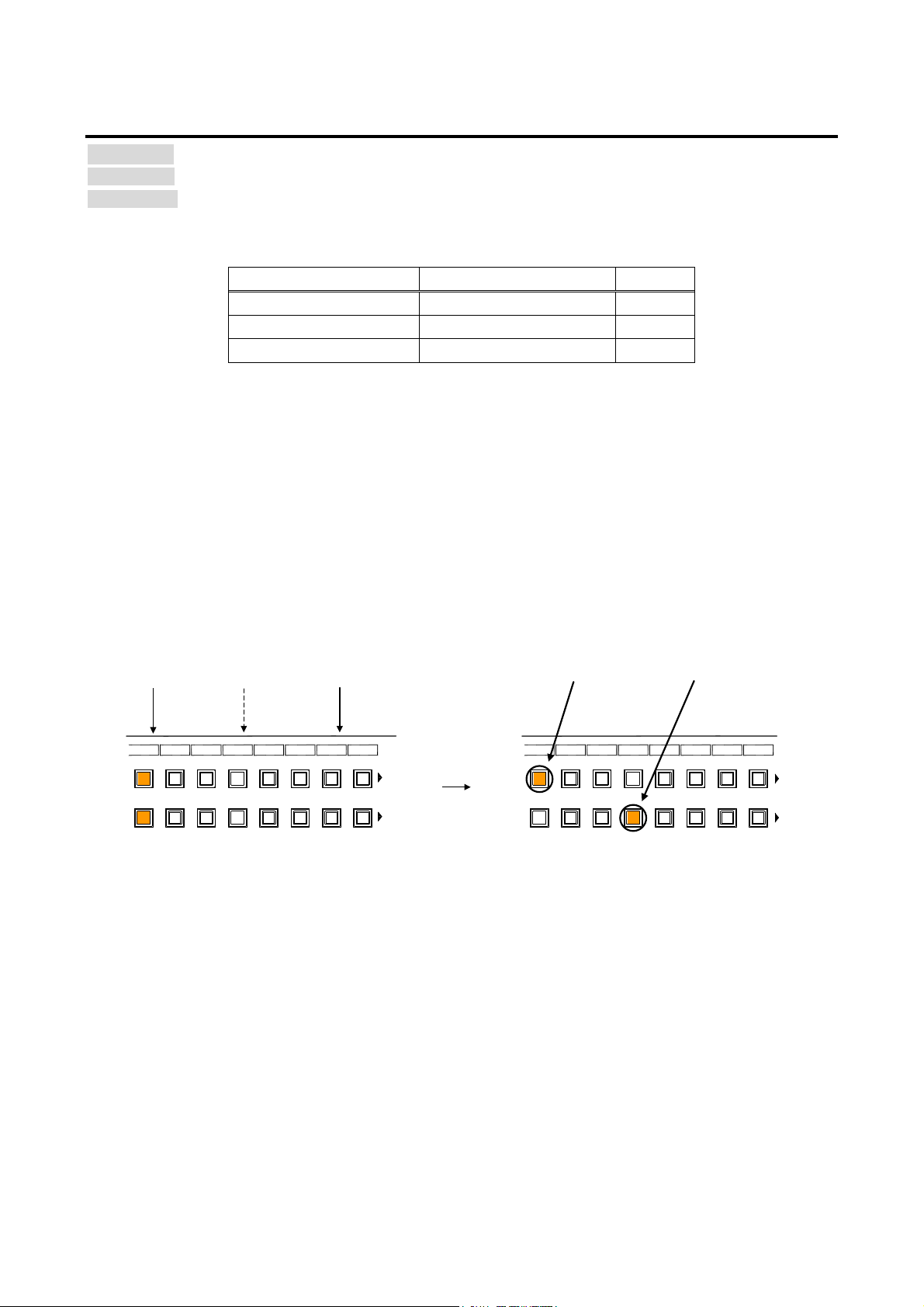
MSD-701UHD / 702UHD / 801UHD/ 802UHD User’s Guide
-*
-*
Input signal “OFF”→” ON”
Input signal “ON”
Input signal “ON”
IN4 has lower pr i ori t y than IN 1.
Input automatic switching will not
be executed .
IN4 has h i gher priority th an IN1.
Input channel automatic switching
will be executed.
PRI * ・ ・・Pri ority for each i nput ch annel
IN 7IN 6IN 5IN 4IN 3IN 2IN 1
OUT 1
OUT 2
IN 8
PRI 7PRI 6PRI 5PRI 4PRI 3PRI 2PRI 1
OFF
PRI 7 PRI 6
PRI 5
PRI 4 PRI 3
PRI 2 PRI 1
OFF
IN 7IN 6IN 5IN 4IN 3IN 2IN 1
OUT 1
OUT 2
IN 8
PRI 7PRI 6PRI 5PRI 4PRI 3PRI 2PRI 1
OFF
PRI 7 PRI 6
PRI 5
PRI 4 PRI 3
PRI 2 PRI 1
OFF
9.8.13 Priority of input channel automatic switching
Menu Top→OUTPUT SETTING→AU T O SWITCH IN G ON / AU TO SWITCH IN G OFF
Setting for Each output channel (Common to OUTA / OUTB)
Setting value [Table 9.8] Setting of priority of input channel autom atic switching
[Table 9.8] Setting of priority of input channel automatic switching
Item Set value Default
Output channel (OUT) 1 to 2
Input channel (IN) 1 to 8
Priority (PRI) 1 (high) to 8(low), OFF OFF
*Setting each i nput channel priority to each out put channel
■ AUTO SWITCH IN G ON
AUTO SWITCHING ON menu switches input si gnal when the input signal changes fr om “OFF ” to “O N”.
The MSD switches input si gnal automatically as follows:
・When the input signal becom e from “OFF” to “ON” and that input channel has higher priorit y than
currently-selected channel or same pri or ity level.
or
・When the input signal becom e from “OFF” to “ON” and the currently- selected channel that have higher
priority than the input signal, but it does not have input signal.
74
[Fig. 9.15] Input chann e l automatic switching “OFF” to “ON”
Page 75
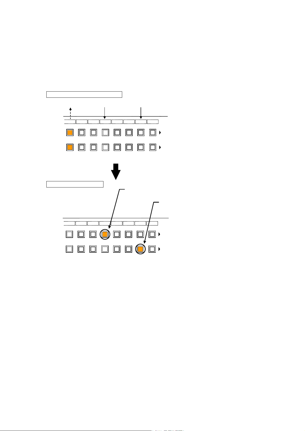
MSD-701UHD / 702UHD / 801UHD/ 802UHD User’s Guide
If the priority is the same as IN1, it will be switched to the
lowest-number channel having input signal.
IN1: “OFF” switched to the channel (IN7) having the second
highest priority.
Input signal “ON”
Input signal “ON” to
“OFF”
Input signal “ON”
PRI *: Automatic switching priority for each input channel
PRI * : Automatic switching priority for each input channel
After automatic channel switchin g
Input channel “ON” to “OFF”
IN 7I N 6IN 5IN 4I N 3IN 2IN 1
OUT 1
OUT 2
IN 8
PRI 1PRI 1PRI 1PR I 1PRI 1PR I 1PRI 1
OFF
PRI 7 PR I 6
PRI 5
PRI 4 PRI 3
PRI 2 PRI 1
OFF
IN 7I N 6IN 5IN 4I N 3IN 2IN 1
OUT 1
OUT 2
IN 8
PRI 1PR I 1PRI 1PRI 1PR I 1PRI 1PRI 1
OFF
PRI 7 PR I 6
PRI 5
PRI 4 PRI 3
PRI 2 PRI 1
OFF
■ AUTO SWITCH IN G OFF
AUTO SWITCHING OFF menu switches input si gnal when the input signal changes fr om “ON” to “OFF”.
The MSD switches input si gnal automatically based on f ollowing c onditions;
・Switches to the input channel hav ing input signal and highest pri ori ty.
・If some channels hav e the same priority, the MSD switches to the lower i nput channel having input signal .
If the priority setting of the input channel is “OFF”, input c hannel automatic switchi ng is not ex ec uted.
You can set channel switching mode for input channel automatic switching from “9.8.15 Channel switching
mode of automatic switching”.
Make sure to press the “MENU/SET” key to apply the settings; other wise, they are not changed.
[Fig. 9.16] Input chann e l automatic switching “ON” to “OFF”
75
Page 76
MSD-701UHD / 702UHD / 801UHD/ 802UHD User’s Guide
9.8.14 Masking time after automatic switching of input channel
Menu Top→OUTPUT SETTING→AUTO SWITCHING MASK
Setting for Each out put channel (Common to OUTA / OUTB)
Setting value 0s000ms to 999s999ms [Default] 0s000ms
You can set the time from when input channel is switched automati c ally until when the next automatic
switching is performed. The automatic switchi ng is not performed during the set time.
【See: 9.8.13 Priority of input channel automati c switching】
9.8.15 Channel switching mode of automatic switching
Menu Top→OUTPUT SETTING→AUTO SWITCHING MODE
Setting for Each out put channel (Common to OUTA / OUTB)
Setting value V&A (Video & Audio) [Default], VIDEO (Video), AUDIO (Audio)
You can set the channel switc hing mode when automatic switching is executed for when the input channel is
switched automati c ally. This setting has pri ority r egar dles s of setting of “8.2 Switching input channel”.
【See: 9.8.13 Priority of input channel automatic switching】
9.8.16 HDBaseT output long reach mode
Menu Top→OUTPUT SETTING→LONG REACH MODE
Setting for Each out put channel (only OUTB)
Setting value
・OFF : Long reach mode OFF Up t o 328 ft. ( 100 m) [Default]
・ON : Long reach mode ON Up to 492 ft. (150 m) .
You can enable / disable HDBaseT output long reach mode.
In long reach mode, up to 1080p (24 bit ) / dot cl oc k 148 MHz is supported when using with IDK’s HDbaseT
product. Select a supported output format.
【See: 9.4.1 Output resolution】
【See: 9.8.10 Deep Color】
76
Page 77
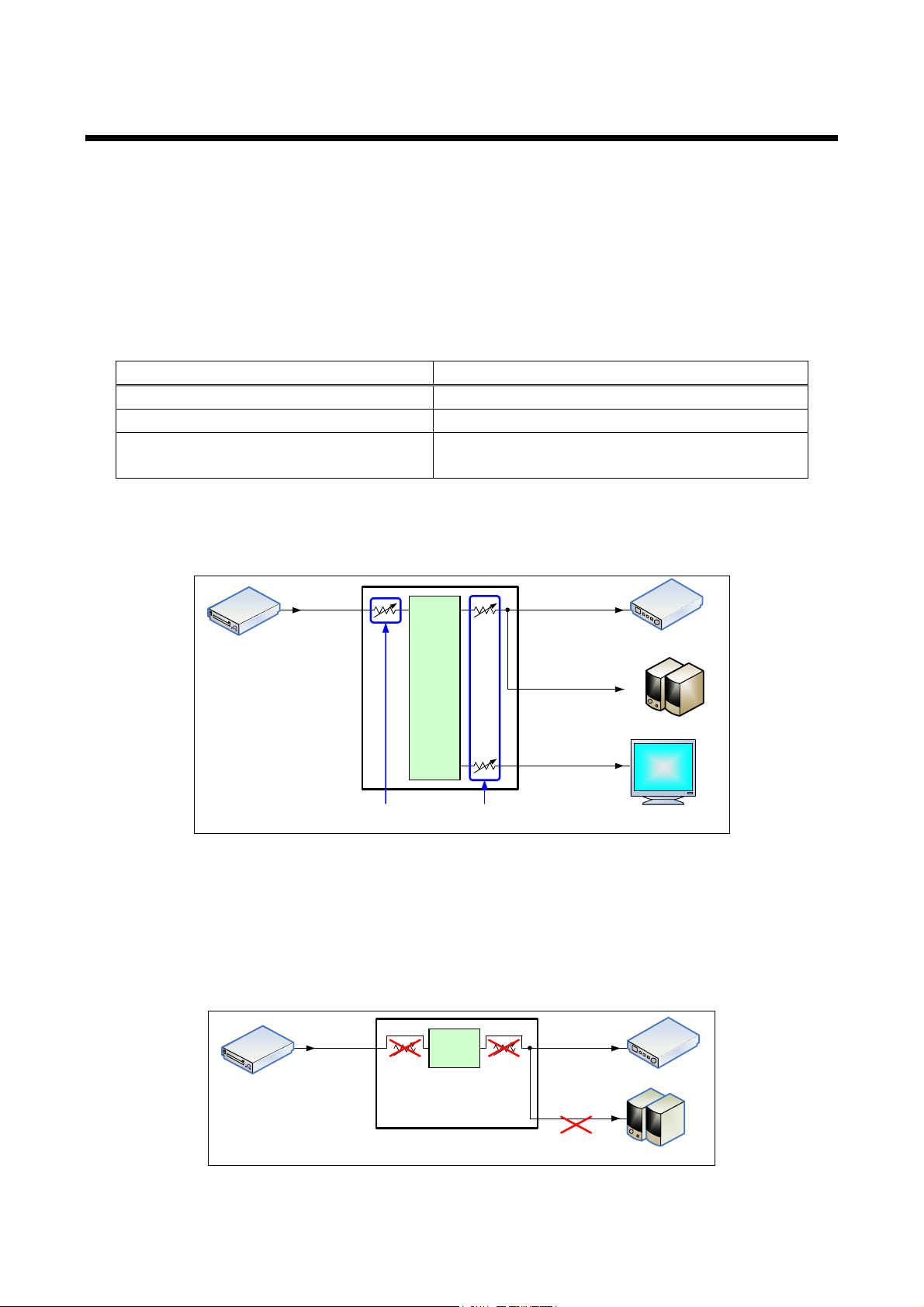
MSD-701UHD / 702UHD / 801UHD/ 802UHD User’s Guide
Audio format
Description
2 channel linear PCM
2ch, 32 kHz to 192 kHz, 16 / 20 / 24 bit
Multi channel linear PCM
8ch, 32 kHz to 192 kHz, 16 / 20 / 24 bit
AC-3, Dolby Digital, DTS, Dolby Digital+,
Bit stream
Analog output
Digital output
5.1ch
5.1ch
Selected 2 ch or down mixed audio
Matrix Switcher
Input level Output level
Digital input
Digital output
Blu-ray disc player
AV Amplifier supporting multi
channels
Amplifier built in speaker
LCD monitor not supporting multi
channels
Any 2 ch or down mixed audio
Switch
Analog audio not output
Adjusting audio volume disabled
Analog output
Digital output
Bitstream signals
Digital input
Blu-ray disc player
AV Amplifier
Amplifier built in speaker
9.9 Audio setti n g
HDMI digital audio support s the following formats. Set audio depending on device connected to the HDMI
output connector .
Only “2 channel linear P CM” can be input by Factory default. If you want t o use “Multi channel linear PCM” or
bit stream signal ( c om pr essed audio), set “Audio format” and “Speaker c onfi guration”.
【See: 9.10.5 Audio format】
【See: 9.10.6 Speaker configuration】
[Table 9.9] Audio format
DTS-HD, Dolby TrueHD, AAC
■ If multi channel linear PCM signal input to digital audio:
If Multi channel linear PCM signal are input to digit al audio, two channels set in “9.9.9 Multi channel audio
output” or down-mixed audio is output to analog audio and sink devices that do not support multi linear PCM.
■ If bit stream signal input to di git a l au dio:
If bit stream signal (compressed audio) such as Dolby Digital is input to HDMI di gital audio, these input audio
signals ar e output to digital audio as they are. They are not output to analog audio, and audio volume cannot
be adjusted.
[Fig. 9.17] Multi chan ne l linear PCM input
[Fig. 9.18] Bit stream s ignal in put
77
Page 78
MSD-701UHD / 702UHD / 801UHD/ 802UHD User’s Guide
9.9.1 Output level
Menu Top→AUDIO→OUTPUT LEVEL
Setting for Each out put channel (Common to OUTA / OUTB)
Setting value -60dB to 10dB [Default] 0dB
You can set the audio output level.
If you change the output lev el while audio output mute is set to “ON”, mute is canceled.
If you set top display of front VFD screen to audio volume adjustment from “9.17.6 Top page”, you can
change and set audio output level from top display.
9.9.2 Output mute
Menu Top→AUDIO→OUTPUT MUTE
Setting for Each out put channel (Common to OUTA / OUTB)
Setting value OFF [Default], ON
You can enable or disable t he audio output mute.
If you set top display of front VFD screen to audio volume adjustment from “9.17.6 Top page”, you can
change and set mute ON/OFF from top display .
9.9.3 Input selection
Menu Top→AUDIO→AUDIO INPUT SELECT
Setting for Each input channel
Setting value DIGITAL [Default], ANALOG1, ANALOG2, ANALOG3
You can select digital or analog audio input to be output.
DIGITAl: Outputs HDMI audio. IN6 and IN7 do not output audio if “9.6.5 Selecting signa l of DVI input
connector” is set to “ANALOG”.
ANALOG1, ANALOG2, and ANALOG3: Output audio that is input to each connector.
9.9.4 Input level
Menu Top→AUDIO→INPUT OFFSET
Setting for Each input channel, each input signal
Setting value -60dB to 0dB [Default] 0dB
You can set the audio input level.
You can correct the gap in audio input levels of each input signal, because audi o input level can be set for
each input connector.
78
Page 79
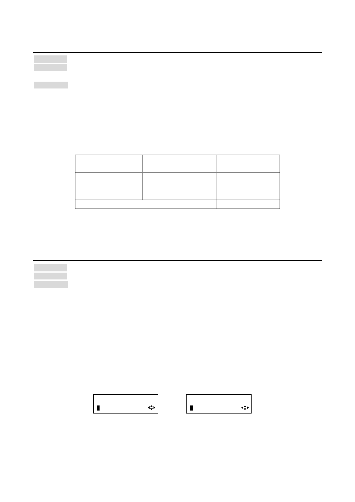
MSD-701UHD / 702UHD / 801UHD/ 802UHD User’s Guide
■
[OUT1 FREQUENCY]
AUTO-A(48kHz)
[OUT1 FREQUENCY]
AUTO-A(48kHz)*
Maximum s am p l i ng f re quency
Sam pl i ng fre quency used l ast tim e
9.9.5 Lip sync
Menu Top→AUDIO→OUTPUT LIP SYNC (Output side) / INPUT LIP SYNC (Input side)
Setting for Output si de : Each output channel (Common to OUTA / OUTB)
Input side : Each input channel, each input signal
Setting value 0FRAME to 8FRAME [Default] 0FRAME
You can adjust the gap bet ween vi deo (motion) and audio (sound).
Up to eight frames can be set f or each input /output channel.
If sampling frequency is 192 kHz and vertical synchronous fr equenc y is 24 Hz / 25 Hz / 30 Hz, the total
maximum value of lip sync input / output channel.
[Table 9.10] Lip sync maximum value
Sampling frequency V er tical synchronous
frequency
Lip sync maximum
value
192 kHz 24 Hz Up to 8 frames*
25 Hz Up to 8 frames*
30 Hz Up to 10 f r am es*
Other conditions Up to 16 frames
*
Up to 8 frames can be set for input / output channel lip sync, but lip sync is
limited to the maximum value.
9.9.6 Sampling frequency
Menu Top→AUDIO→SAMPLING FREQUENCY
Setting for Each out put channel (Common to OUTA / OUTB)
Setting value
・AUTO-A [Default]
・AUTO-B
You can set the sampling fr equenc y of digital audio output.
“AUTO-A” or “AUTO-B”:
Outputting digital audio at the maximum sampling frequency supported by the sink device that is connected to
OUTA (HDMI for AUTO-A) or OUTB (HDBaseT for AUTO-B).
At this time, the sampli ng frequenc y that is actually output i s di spl ay ed in par entheses. In case EDID cannot
be read from the sink dev ic e, t he sampling frequency that was used the last time is selected with “*” on its
right side.
・192kHz
・96kHz
・88.2kHz
・48kHz
・44.1kHz
・32kHz
79
Page 80
MSD-701UHD / 702UHD / 801UHD/ 802UHD User’s Guide
output connector
output connector
output connector
ANALOG&DIGITAL [Default]
Can be output
Partly*
Partly*
ANALOG
Can be output
Cannot be output
Cannot be output
9.9.7 Audio output connector
Menu Top→AUDIO→AUDIO OUTPUT
Setting for Each out put channel (OUTA / OUTB)
Setting value [Table 9.11] Settings of audio out put control
You can control the audio outputs of the audio output connector, HDMI output connect or, and HDB aseT
output connector .
[Table 9.11] Settings of audio output control
Setting value
DIGITAL Cannot be output Partly* Partly*
*If “DVI MODE” is selected for “9.8.1 Output mode”, audio is not output to t he HDMI output connector
regardless of t he setting of this menu.
Analog audio
HDMI
HDBaseT
9.9.8 Digital audio output connector
Menu Top→AUDIO→DIGITA L OUTPUT
Setting for Each out put channel (OUTA / OUTB)
Setting value ON [Default] OFF
You can control the audio outputs of the HDMI output connector and HDBaseT output connector.
The MSD distributes the same audio to the HDMI output connector and HDBaseT output connector. You can
enable /disabl e the audio output for each connector.
9.9.9 Multi channel audio output
Menu Top→AUDIO→MULTI AUDIO
Setting for Each out put channel (Common to OUTA / OUTB)
Setting value
・DOWN MIX [Default]
・CH1/CH2 STEREO
・CH3/CH4 STEREO
You can select audio to be output to a sink device that does not support multi-channel linear PCM or analog
audio for when multi -channel linear PCM audio is input from an HDMI input connector.
You can select audi o from “DOWN MIX” (m ulti-channel audio is down mixed), “STEREO” (stereo audi o), or
“MONO” (monaur al audio).
・CH5/CH6 STEREO
・CH7/CH8 STEREO
・CH1/CH2 MONO
・CH3/CH4 MONO
・CH5/CH6 MONO
・CH7/CH8 MONO
80
Page 81
MSD-701UHD / 702UHD / 801UHD/ 802UHD User’s Guide
Multi channel linear PCM audio
OUTA sink device
OUTB sink device
DOWN MIX
Not supported
Not supported
DOWN MIX
Supported
Not supported
DOWN MIX
Not supported
Supported
DOWN MIX
MULTI [Default]
Not supported
Not supported
DOWN MIX
Supported
Not supported
MULTI
Not supported
Supported
MULTI
9.9.10 Multi channel audio output priority
Menu Top→AUDIO→OUT AUDIO PRIORITY
Setting for Each out put channel (Common to OUTA / OUTB)
Setting value DOWN MIX , MULTI [Default]
If outputting multi channel linear PCM to a sink device, the MSD checks whether the si nk dev ice supports
multi channel linear PCM. If the sink device supports multi channel linear PCM, the MSD outputs audio with
the format. If the sink dev ic e does not support the format, the MSD outputs audio accor ding to the setting of
“9.9.9 Multi channel audio output”.
You can set the priority as shown below for if some sink devices that are connected to OUTA or OUTB
support multi linear PCM while others do not.
[Table 9.12] Audio output
Setting value
If no sink device is connected, it is treated as a sink device that does not support m ulti channel linear PCM.
Output audio
81
Page 82

MSD-701UHD / 702UHD / 801UHD/ 802UHD User’s Guide
9.9.11 Test tone
Menu Top→AUDIO→TEST TONE
Setting for Each out put channel (Common to OUTA / OUTB)
Setting value
Test tone:
OFF [Default], 1kHz, 400Hz
Speaker:
・ALL [Default] ・LOW FREQUENCY EFFECT
・FRONT L/R ・FRONT CENTER
・REAR L/R ・REAR LEFT
・REAR L/R CENTER ・REAR RIGHT
・FRONT LEFT ・REAR LEFT CENTER
・FRONT RIGHT ・REAR RIGHT CENTER
Since test tone can be out put only to specific speakers, you can c hec k the posi tion of the speakers.
For “LOW FREQUENCY EFFECT”, only test t one of 30 Hz is output.
【See: 9.10.6 Speaker configuration】
82
Page 83
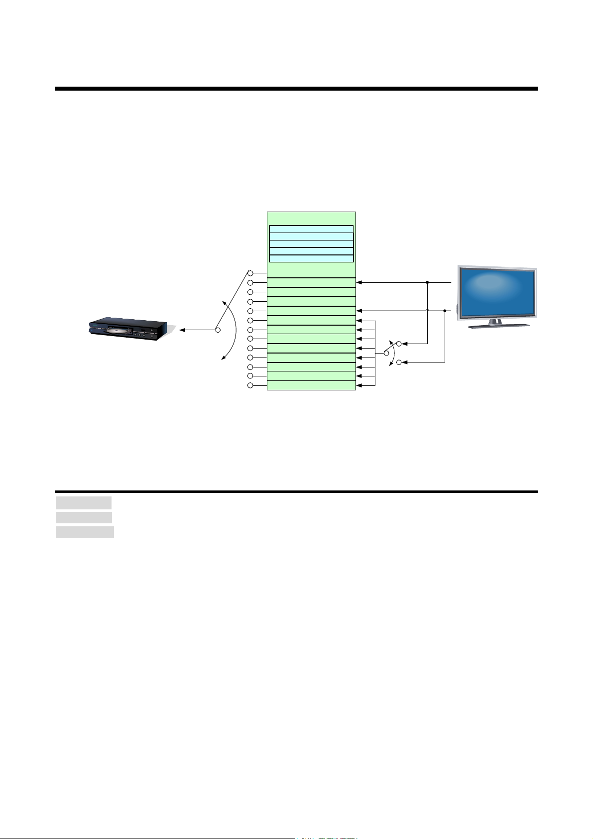
MSD-701UHD / 702UHD / 801UHD/ 802UHD User’s Guide
■
LCD
Ex tern a l EDID OUT 2B
Blu-ray player
Step.1
Step.2
IN 1
-
IN 8
Copied EDI D 1
Copied EDI D 2
Copied EDI D 3
Copied EDI D 4
Copied EDI D 5
Copied EDI D 6
Copied EDI D 7
Copied EDI D 8
Step.3
Changing audio for m at
Changing Deep Color input
Changing speaker configuration
Changing PC resolution
Changing AV resolution
Built-in EDID
-
OUT 1A
OUT 2B
Ex tern a l EDID OUT 2A
Ex tern a l EDID OUT 1B
Ex tern a l EDID OUT 1A
9.10 EDID (E xtende d Display Identific ation Data)
You can set or customiz e EDID to be sent t o the source device. Change the setti ng as needed.
Setting EDID
Step 1 If you use copied EDID, copy the t ar get EDID from the sink device.
Step 2 Set the EDID that will be sent to the source devic e.
Step 3 If you use built -in EDID, custom ize the data as usage.
[Fig. 9.19] Setting EDID (MSD-802UHD)
9.10.1 EDID
Menu Top→EDID→EDID DATA
Setting for Each input channel ( only digital input)
Setting value
・INTERNAL EDID [Default]
・OUT1A MONITOR
・OUT1B MONITOR
You can set the EDID to be sent to the source devic e from built-in EDID (“INTERNAL EDID”), connected sink
device’s EDID (“MONITOR”) and copied EDID (“COPY DATA”).
EDID copied from a sink devic e will be displayed if any.
The setting of this menu is not updat ed until the MENU/SET key is pressed. Make sure to press the
MENU/SET key to update the setti ng.
・OUT2A MONITOR
・OUT2B MONITOR
・COPY DATA1 to COPY D ATA8
【See: 9.10.7 Copying EDID 】
83
Page 84

MSD-701UHD / 702UHD / 801UHD/ 802UHD User’s Guide
9.10.2 Resolution for PCs
Menu Top→EDID→PC RESOLUTION
Setting for Each input channel
Setting value
・SVGA (800x600)
・XGA (1024x768)
・720p (1280x720)
・WXGA (1280x768)
・WXGA (1280x800)
・Quad-VGA (1280x960)
・SXGA (1280x1024)
・WXGA (1360x768)
・WXGA (1366x768)
・SXGA+ (1400x1050)
・WXGA+ (1440x900)
・WXGA++ (1600x900)
・UXGA (1600x1200)
・WSXGA+ (1680x1050)
・1080i (1920x1080)
・1080p (1920x1080)
[Default] IN1, IN2 : 2160p@60 (3840x2160)
IN3 to IN7 : 1080p (1920x1080)
IN8 : 2160p@30 (3840x2160)
*1
IN1, IN2, IN8
*2
IN1, IN2
You can set the resolution r equested to be output from source devices.
This setting will also be appl ied for controlli ng output r esolution when AV devices (such as Blu-ray players)
are connected vi a HDMI. For digital input, this setting will be valid only if “INTERNAL EDID” is selected for
“9.10.1 EDID”.
The setting of this menu is not updat ed until the MENU/SET key is pressed. Make sure to press the
MENU/SET key to update the setti ng.
Timing of 720p, 1080i, 1080p, and 2160p is the same as that of HD signal meeting the CEA-861D standar d.
For other resolutions, timings meet the VESA DMT or VESA CVT standards.
Set the maximum available resolution for EDI D, but the lower resolutions are also supported. Select the
resolution supported by the connected PC.
You can select 2160p (4096x2160) resolution from “9.10.3 Input resolution for AV devices”.
If a source device that does not support 4K is connected to the input connector with 4K EDID settings, the
source device may out put DVI signal meaning audio is not output. In or der to out put HDMI signal from the
source device, change the settings of this menu and “9.10.3 Input resolution for AV devices
other than 4K.
・WUXGA (1920x1200)
・QWXGA (2048x1152)
・WQHD (2560x1440)
・WQXGA (2560x1600)
*1
*1
・2160p@30 (3840x2160)
・2160p@60 (3840x2160)
” to a value
*1
*2
84
Page 85
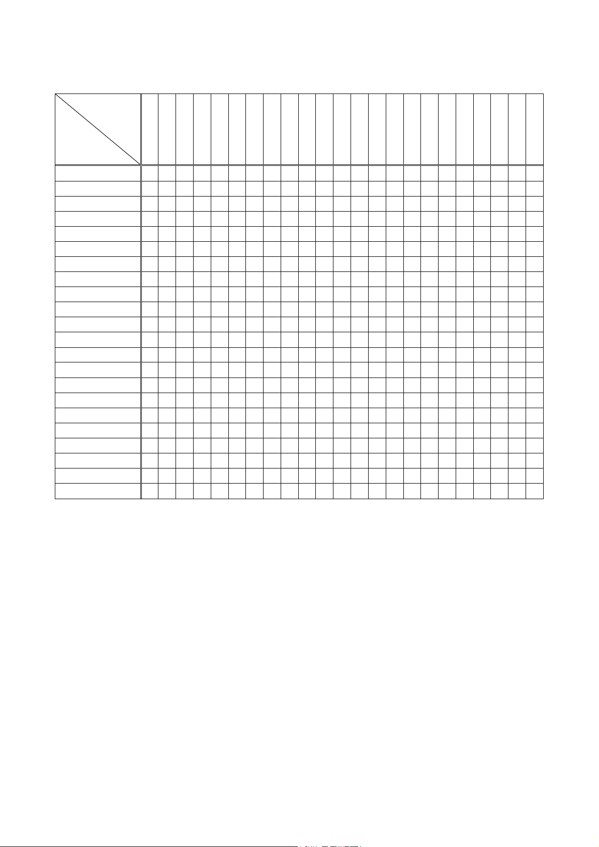
settings
Input
resolution
Supported
resolution
MSD-701UHD / 702UHD / 801UHD/ 802UHD User’s Guide
[Table 9.13] Supported resolution
640×480
800×600
1024×768
1280×720
1280×768
1280×800
1280×960
1280×1024
1360×768
1366×768
1400×1050
1440×900
1600×900
1600×1200
1680×1050
1920×1080i
1920×1080p
1920×1200
2048×1152
2560 x 1440
2560 x 1600
2160p (30p)
2160p (60p)
800x600
1024x768
1280x720[D4]
1280x768
1280x800
1280x960
1280x1024
1360x768
1366x768
1400x1050
1440x900
1600x900
1600x1200
1680x1050
1920x1080i[D3]
1920x1080p[D5]
1920x1200
2048x1152
2560x1440
2560x1600
2160p (30p)
2160p (60p)
Y Y N N N N N N N N N N N N N N N N N N N N N
Y Y Y N N N N N N N N N N N N N N N N N N N N
Y Y Y Y N N N N N N N N N N N N N N N N N N N
Y Y Y Y Y N N N N N N N N N N N N N N N N N N
Y Y Y Y Y Y N N N N N N N N N N N N N N N N N
Y Y Y Y Y Y Y N N N N N N N N N N N N N N N N
Y Y Y Y Y Y Y Y N N N N N N N N N N N N N N N
Y Y Y Y Y Y Y Y Y N N N N N N N N N N N N N N
Y Y Y Y Y Y Y Y N Y N N N N N N N N N N N N N
Y Y Y Y N Y Y Y N Y Y N N N N N N N N N N N N
Y Y Y Y N Y Y Y N Y Y Y N N N N N N N N N N N
Y Y Y Y N Y Y Y N Y Y Y Y N N N N N N N N N N
Y Y Y Y N Y Y Y N Y Y Y Y Y N N N N N N N N N
Y Y Y Y N Y Y Y N Y Y Y Y Y Y N N N N N N N N
Y Y Y Y N N N N N N N N N N N Y N N N N N N N
Y Y Y Y N N Y Y N Y Y Y Y Y Y N Y N N N N N N
Y Y Y N N Y Y Y N N Y Y Y Y Y N Y Y N N N N N
Y Y Y N N N Y Y N N Y Y Y Y Y N Y Y Y N N N N
Y Y Y N N N Y Y N N Y Y Y Y Y N Y N Y Y N N N
Y Y Y N N N N Y N N Y Y Y Y Y N Y N Y Y Y N N
Y Y Y N N N N Y N N Y Y Y Y Y N Y N Y N Y Y N
Y Y Y N N N N Y N N Y Y Y Y Y N Y N Y N N Y Y
Y: Supported , N: Not supported
85
Page 86
MSD-701UHD / 702UHD / 801UHD/ 802UHD User’s Guide
1920×1080p
9.10.3 Input resolution for AV devices
Menu Top→EDID→AV RESOLUTION
Setting for Each input channel (only digital input)
Setting value
・AUTO [Default]
・UNUSED
・480p
・720p
*1
N1, IN2, IN8
*2
IN1, IN2
・1080i
・1080p
・2160p@30
*1
・2160p@60 4:2:0
*1
・2160p@60 4:4:4
・4096x2160@30
・4096x2160@60 4:2:0
・4096x2160@60 4:4:4
You can set the resolution r equested to be output from AV devices (such as Blu-ray players).
This setting will be v alid if “INTERNAL EDID” is selected for “9.10.1 EDID“.
Normally, set this menu to “AUTO” to set resolution for AV devices according to “9.10.2 Resolution for PCs”
automatically.
“UNUSED” disables the E DID for AV devices. If you select “AUTO” and the r esol ution output from the PC is
different f r om the resolut ion set in Properties, the problem m ay be solv ed by selecting “UNUSED”.
If there is a potenti al to connec t both PCs and AV devices with different resol utions (for example, PC with
WXGA (1366x768), Blu-ray disc player with 1080p), set the PC resolution in “9.10.2 Resolution for PCs” and
select the AV resolution in this menu. However, some PCs and AV devices may select the higher resolution of
the resoluti ons set i n “9.10.2 Resolution for PCs” or this menu.
If a source device that does not support 4K is connected to the input connector with 4K EDID settings, the
source device may out put DVI signal meaning audio is not output. In or der to out put HDMI signal from the
source device, change the settings of this menu and “9.10.2 Resolution for PCs” t o a value other than 4K.
The setting of this menu is not updat ed until the MENU/SET key is pressed. Make sure to press the
MENU/SET key to update the setti ng.
[Table 9.14] Input resolutions when “AUTO” is selected
*2
*1
*1
*2
PC
Resolution
640×480
800×600
1024×768
1280×720
1280×768
1280×800
1280×960
1280×1024
1360×768
1366×768
1400×1050
1440×900
1600×900
1600×1200
1680×1050
1920×1080i
1920×1200
2048×1152
2560 x 1440
2560 x 1600
2160@30
2160@60 4:4:4
AV
Resolution
480p
720p
1080i
1080p
2160p@60 4:2:0
2160p@60 4:4:4
Note:
If you select “UNUSE D”, the sett ings of “9.10.4 Deep Color”, “9.10.5 Audio format”, “9.10.6 Speaker
configuration” will be disabled and audio is not output because the source device outputs signal through DVI
mode.
86
Page 87
MSD-701UHD / 702UHD / 801UHD/ 802UHD User’s Guide
DTS
Can be set (OFF)
ON: 32 / 44.1 / 48 / 96 (48)
Can be set (OFF)
9.10.4 Deep Color
Menu Top→EDID→DEEP COLOR INPUT
Setting for Each input channel (only digital input)
Setting value 24-BIT COLOR [Default], 30-BIT COLOR
You can set the color depth to be out put f r om the source dev ice.
This menu is valid only if you select “INTERNAL EDID” for “9.10.1 EDID“ and you select a resolution other
than “UNUSED” for “9.10.3 Input resolu tion for AV devices“.
If you select “30-BIT COLOR”, compared to “24-BIT COLOR”, “30-BIT COLOR” is transmi tted using a higher
clock frequency, which may cause noise if a cable with a bad quality or a long cable is connected. In such a
case, the noise may be removed by setting the color to “24-BIT COLOR”.
The setting of this menu is not updat ed until the MENU/SET key is pressed. Make sure to press the
MENU/SET key to update the setti ng.
9.10.5 Audio format
Menu Top→EDID→AUDIO FORMAT
Setting for Each input channel ( only digital input)
Setting value [Table 9.15] Audio format
[Table 9.15] Audio format
Audio format
PCM
Dolby Digital
AAC Can be set (OFF ) ON: 32 / 44.1 / 48 / 88.2 / 96 (48)
Dolby Digital+
DTS-HD Can be set (OFF) ON: 44.1 / 48 / 88.2 / 96 / 176.4 / 192 (192)
Dolby TrueHD
Default values are shown in par entheses.
You can set the audio format and maximum sampling frequency to be output from a source devi c e.
This menu will be valid only if you selec t “INTERNAL EDID” for “9.10.1 EDID” and you select a resolution
other than “UNUSED” for “9.10.3 Input resolution for AV devices”.
The setting of this menu is not updat ed until the MENU/SET key is pressed. Make sure to press the
MENU/SET key to update the setti ng.
ON / OFF
Cannot be set
Can be set (OFF)
Can be set (OFF)
32 / 44.1 / 48 / 88.2 / 96 / 176.4 / 192 (48)
ON: 32 / 44.1 / 48 (48)
ON: 32 / 44.1 / 48 (48)
ON: 44.1 / 48 / 88.2 / 96 / 176.4 / 192 (96)
Maximum sampling fr equenc y ( k Hz)
87
Page 88
MSD-701UHD / 702UHD / 801UHD/ 802UHD User’s Guide
REAR
FLH
FLW
FL
FLC
FC
FCH
FRC
FRH
FR
FRW
LFE
TC
RL
RLC
RC
RRC
RR
FRONT
FLH
FLW
FL
FLC
FC
FCH
FRC
FRH
FR
FRW
LFE
TC
RL
RLC
RC
RRC
RR
Front Left High
Front Left Wide
Front Left
Front Left Center
Front Center
Front Center High
Front Right Center
Front Right High
Front Right
Front Right Wide
Low Frequency Effect
Top Center
Rear Left
Rear Left Center
Rear Center
Rear Right Center
Rear Right
9.10.6 Speaker configuration
Menu Top→EDID→SPEAKER
Setting for Each input channel ( only digital input)
Setting value Setting mode : AUTO [Default], MANUAL
Each speaker : ON, OFF
The number of speakers: 1 to 8
[Table 9.16] Default speaker configuration
The number of
speakers
1 OFF OFF ON OFF OFF OFF OFF OFF OFF OFF OFF
2 [Default] ON OFF OFF OFF OFF OFF OFF OFF OFF OFF OFF
3 ON ON OFF OFF OFF OFF OFF OFF OFF OFF OFF
4 ON ON ON OFF OFF OFF OFF OFF OFF OFF OFF
5 ON ON OFF ON OFF OFF OFF OFF OFF OFF OFF
6 ON ON ON ON OFF OFF OFF OFF OFF OFF OFF
7 ON ON ON ON ON OFF OFF OFF OFF OFF OFF
8 ON ON ON ON OFF OFF ON OFF OFF OFF OFF
FL/
FR
LFE FC
RL/
RR
RC
FLC/
FRC
RLC/
RRC
FLW/
FRW
FLH/
FRH
TC FCH
88
[Fig. 9.20] Speaker configuration
Page 89
MSD-701UHD / 702UHD / 801UHD/ 802UHD User’s Guide
■
You can set the speaker configuration of multi channel audio.
This menu is valid only if you select “INTERNAL EDID” for “9.10.1 EDID“, you selec t a resol ution other than
“UNUSED” for “9.10.3 Input resolution for AV devices”.
If you select “AUTO” f or the setting mode and set the number of speakers, the speaker configuration will be
set t o the default setting that is shown in “[Table 9.16] Default speaker configuration”.
To change the default configuration, set the mode to “MANUAL” and set each speaker to ON/OFF individually.
If the number of speakers exceeds the available value, the “DATA INVALID” message is displayed and the
settings will not be applied.
The setting of this menu is not updat ed until the MENU/SET key is pressed. Make sure to press the
MENU/SET key to update the setti ng.
9.10.7 Copying EDID
Menu Top→EDID→MONITOR EDID COPY
Setting for COPY EDID No.1 to No.8
Setting value OUT1A, OUT1B, OUT2A, OUT2B
EDID of the sink device is loaded and registered to the MSD.
Up to eight EDID can be registered.
Copying EDID (Ex: MSD-802UHD)
Step.1: Select output channel (OUT1A to OUT2B) which is connected to si nk device
Step.2: Select the number of COPY EDID (No.1 to No.8)
Step.3: Set the name of the E DID using ASCII code 20 to 7D (up to 10 character s)
Step.4: Press the “MENU/SET” key to register an EDID
89
Page 90
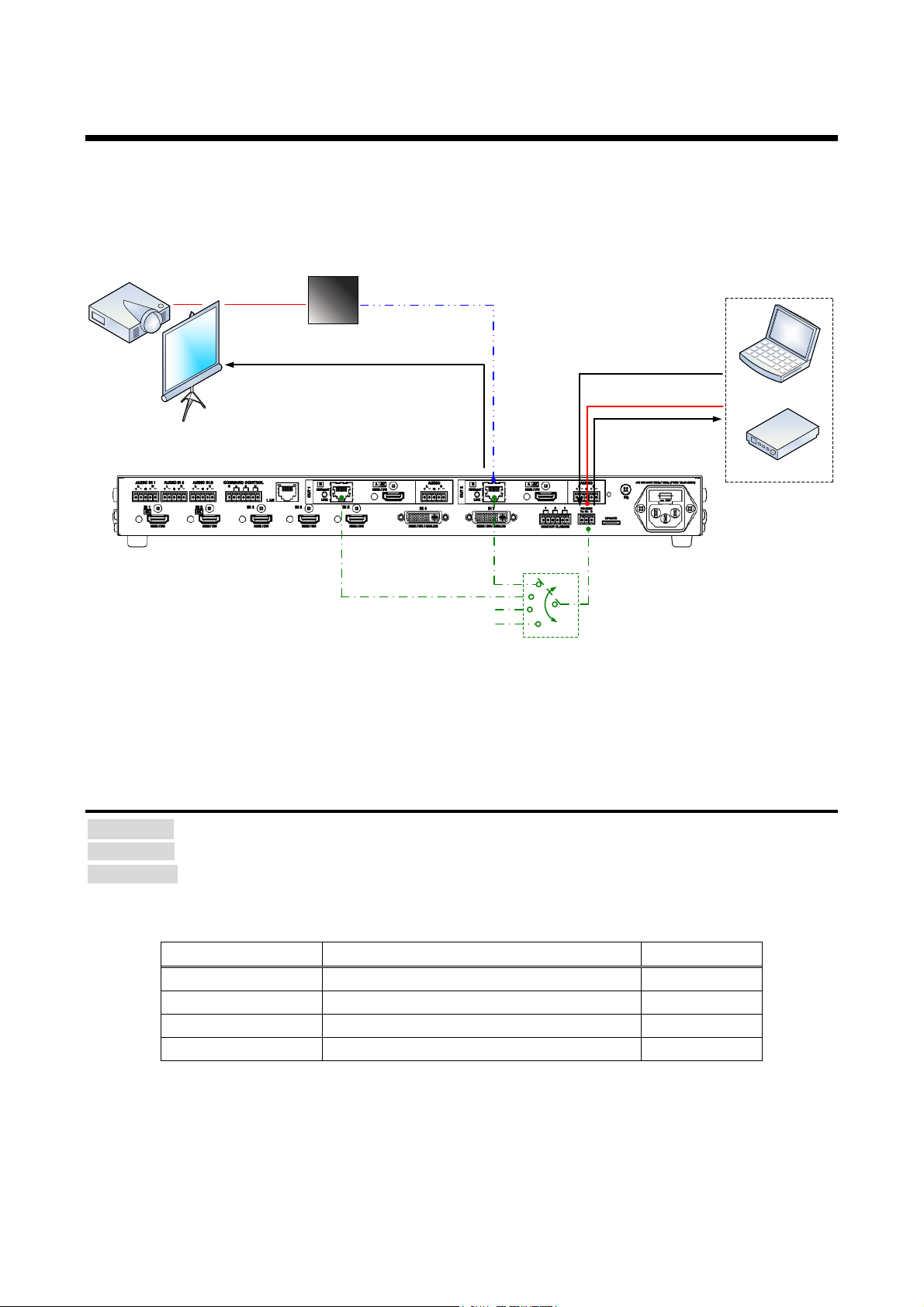
MSD-701UHD / 702UHD / 801UHD/ 802UHD User’s Guide
Laptop
Projector
RS-232C cable
Twisted pair cable
RS-232C cable
Communication command control to MSD
Outputting control commands to
external devices
Outputt ing control comm ands to ext er nal devices
Power amp.
IN8
RS-232C transmission setting between control
devices (OUT B SCI CO NNE CT )
Not connected (RS-232C connector operates nor m ally)
Twisted pair cable
receiver
Data bit length [bit]
8, 7
8
Stop bit [bit]
1, 2
1
9.11 RS-232C
The RS-232C connector of the MSD can output communication command contr ol from PCs and can output
control command to external devices from the MSD. The operation mode will be switched according to “9.11.2
RS-232C operation mode”.
【See: 9.13 Setting control c ommand】
[Fig. 9.21] RS-232C communication
9.11.1 RS-232C communication setting
Menu Top→COM PORT→PARAMETERS
Setting for RS-232C connector, OUT1B connector, OUT2B connector, IN8 connector
Setting value [Table 9.17] RS-232C settin g i t ems
Setting item Setting value Default
Baud rate [bps] 4800, 9600, 19200, 38400 9600
Parity check NONE, EVEN, ODD NONE
You can set RS-232C communicati on.
The setting of this menu is not updat ed until the MENU/SET key is pressed. Make sure to press the
MENU/SET key to update the setting.
[Table 9.17] RS-232C setting items
90
Page 91
MSD-701UHD / 702UHD / 801UHD/ 802UHD User’s Guide
mode”.
OUT1B
Communication between MSD’s RS-232C connector and an RS-232C connector of
PC to MSD or control command out put from MSD t o external dev ic es.
9.11.2 RS-232C operation mode
Menu Top→COM PORT→FUNCTION
Setting for RS-232C connector, OUT1B connector, OUT2B connector, IN8 connector
Setting value RECEIVER,TRANSMITTER
[Default]
RS-232C connector, IN8 connector: RECEIVER
OUT1B connector, OUT2B connector: TRAMSMITTER
You can set the operation mode to “RECEIVER” mode in which the MSD is contr olled externally or
“TRANSMITTER” mode in which the MSD contr ols peripheral devices.
The setting of this menu is not updat ed until the MENU/SET key is pressed. Make sure to press the
MENU/SET key to update the setti ng.
9.11.3 RS-232C HDBaseT connection
Menu Top→COM PORT→OUT B SCI CONNECT
Setting value [Table 9.18] RS-232C operat ion
You can set the communication between MSD’s RS-232C connect or and an RS -232C c onnec tor of twisted
pair cable transmit ter or receiver that is connected t o HDBaseT I/O connector.
[Table 9.18] RS-232C operation
Setting value Operation
OFF [Default] MSD’s RS-232C connector operates in the mode that is set in “9.11.2 RS-232C operation
OUT2B
IN8
twisted pair cable transmitter or receiver that is connected to HDBaseT I/O connector .
The MSD’s RS-232C connector cannot be used for communication command control from
【See: 9.11 RS-232C】
91
Page 92
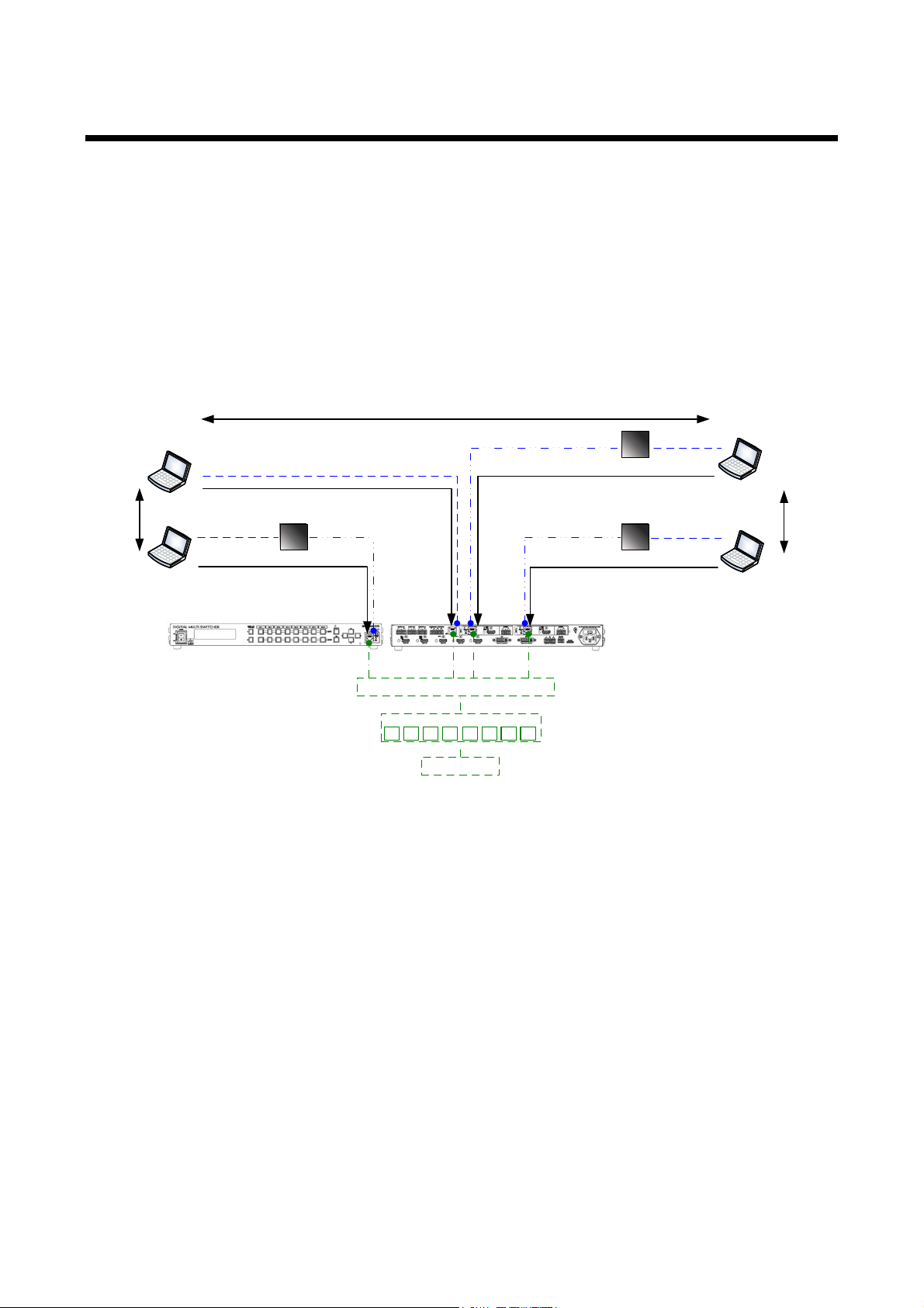
MSD-701UHD / 702UHD / 801UHD/ 802UHD User’s Guide
Twisted pair cable
transmitter
LAN cable
Communication command control to MSD
Switching hub
Bidirectional communication
Control unit
Twisted pair cable
Laptop
Laptop
Communication command control to MSD
MSD-802UHD (Front)
Communication command control to MSD
LAN cable
Laptop
Bidirectional
communication
1 2 3 4 5 6 7 8
Communication command control to MSD
Laptop
Bidirectional
communication
MSD-802UHD (Rear)
Twisted pair cable
LAN cable
Twisted pair cable
LAN cable
Twisted pair cable
receiver
Twisted pair cable
receiver
Connections
9.12 LAN
■ LAN communication
The internal switc hing hub enables connections between the M S D’s LAN connector and LAN connectors of
twisted pair cable transmitter and receiver that ar e connect ed to HDBaseT I/O connectors. Bidirectional
communicati on is al so available.
Communication command control from PC to the MSD and control command output from the MSD to external
devices can be executed from all LAN ports. Operation mode will be switched acc or ding to the setting of
“9.12.2 LAN operation mode”. The MSD has eight connections that can be set indivi dually .
【See: 9.13 Setting control c ommand】
[Fig. 9.22] LAN operation
The MSD does not support automatic acquisition of IP address using DHCP (Dy nam ic Host Configuration
Protocol). If you use the MSD in a network with DHCP, keep a fixed IP address. If c ontrolling peripheral
devices connected over LAN from the MSD, keep several fix ed IP addresses.
92
Page 93
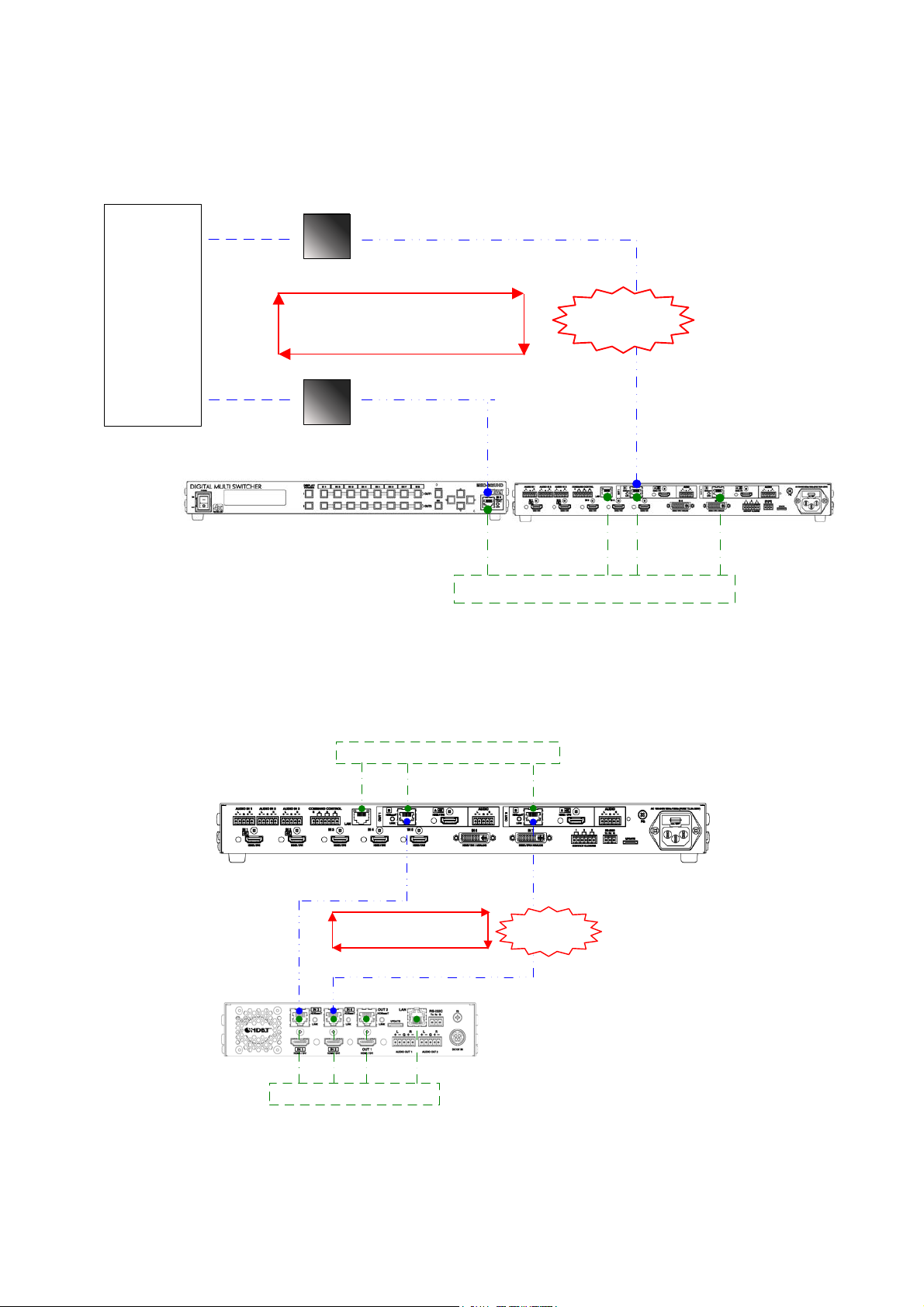
MSD-701UHD / 702UHD / 801UHD/ 802UHD User’s Guide
Twisted pair cable
Switching hub
Switching hub
LAN cable
LAN cable Twisted pair cable
Other manufacturer’s device
MSD-802UHD (Rear)
Loop
MSD-802UHD (Front)
Twisted pair cable
receiver
Twisted pair cable
transmitter
MSD-802UHD
Switching hub
MSD-402
Loop problem
Twisted pair cable
Twisted pair cable
Switching hub
■ LAN loop problem
The MSD includes 3-port switching hub function. The network m ay be down due to loop problem.
[Fig. 9.23] Loop problem with other manufacture’s device
[Fig. 9.24] Loop problem with IDK’s device
93
Page 94
MSD-701UHD / 702UHD / 801UHD/ 802UHD User’s Guide
Operation mode
Receiver mode
Transmitter
Operation mode
RECEIVER [Default]
TRANSMITTER
Destination IP addr ess
0.0.0.0 to 255.255.255.255
OFF: Not use [Default]
number*1
9.12.1 IP address/Subnet mask/Gateway address
Menu IP address: Top→LAN→IP ADDRES S
Subnet mask: Top→LAN→SUBNET MASK
Gateway address: Top→LAN→GATEWAY ADDRESS
Setting value [Default] IP address: 192.168.1.199
Subnet mask: 255.255.255.0
Gateway address: 192.168.1.200
You can set IP address, subnet mask, and gateway address.
The setting of this menu is not updat ed until the MENU/SET key is pressed. Make sure to press the
MENU/SET key to update the setti ng.
9.12.2 LAN operation mode
Menu Top→LAN→FUNCTION
Setting for Each connection
Setting value [Table 9.19] Setting items of LAN operation mode
[Table 9.19] Setting items of LAN operatio n mode
Setting
-
[Default] 192.168.1.198
PJLink protocol connec tion - ON: Use
Destination c onnec tion
- 1 to 65535 [Default] 1100
PJLink protocol password*2 - 20, 30 to 39, 41 to 5A, 61 to 7A in ASCII c ode
(in hex) [Default] 20 ( space)
*1
If selecting “ON” for PJLink pr otocol, the target port number is fixed at “4352”.
*2
Up to 32 characters. If you do not want the password authentication, you do not need to set the item.
You can set the LAN operation m ode c onsi sting of “RECEIVER” mode that contr ols the M S D exter nally and
“TRANSMITTER” mode that controls peripheral dev ic es fr om the MSD.
If you select “TRANSMITT E R” mode, y ou need to set the i nformation of connecting dev ic e.
The setting of this menu is not updat ed until the MENU/SET key is pressed. Make sure to press the
MENU/SET key to update the setti ng.
94
Page 95
MSD-701UHD / 702UHD / 801UHD/ 802UHD User’s Guide
9.12.3 TCP port number
Menu Top→LAN→PORT NUMBER
Setting for Each connection
Setting value [Table 9.20] Settings of TCP port number
[Table 9.20] Settings of TC P port num be r
For Setting value
Communication c ommand control 23, 1100, 6000 to 6999
WEB br owser control 80, 5000 to 5999
[Default] Connections 1 to 3 = 1100; Connections 4 to 6 = 23;
Connections 7, 8 = 80
You can set the TCP port number to contr ol the MSD externally.
This setting will v alid if “RECEIVER” is selected for “9.12.2 L AN op erat ion mod e”.
Each connecti on will be div ided into connections for comm unication command control and WEB browser
depending on the set port num ber s.
The setting of this menu is not updat ed until the MENU/SET key is pressed. Make sure to press the
MENU/SET key to update the setti ng.
9.12.4 M AC address
Menu Top→LAN→MAC ADDRESS
You can display the MAC address.
95
Page 96
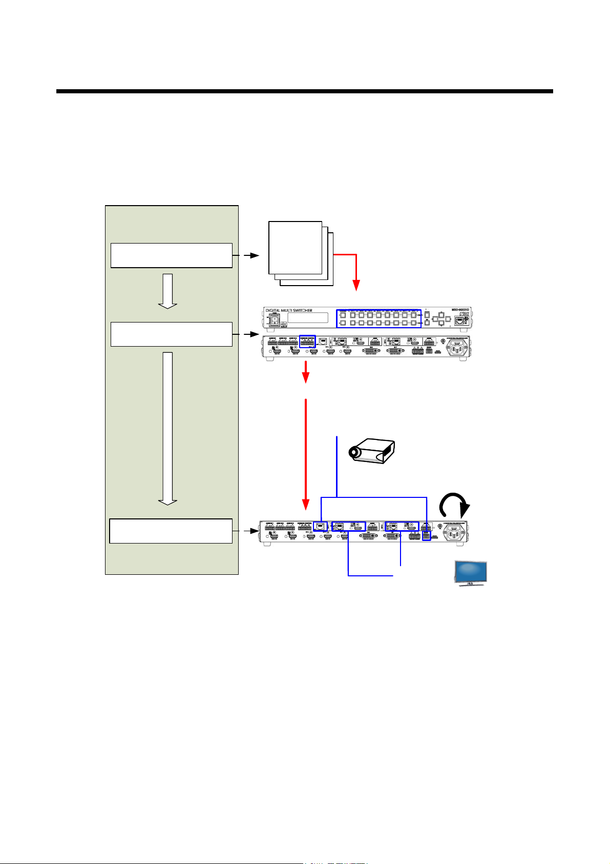
MSD-701UHD / 702UHD / 801UHD/ 802UHD User’s Guide
Regi stering control /reply
command
Executing control command
(from menu/key)
<Procedure>
As sociatin g control comm and
Step (1)
Step (2)
Step (3)
As sociatin g control comm and with switc h or ke y
Regi stering control /reply command
制御・返信
コマンド
制御・返信
コマンド
Control/reply
command
Executing control command
Int ernal loopback
communication
command
Sw itching ch annel
LAN / RS-232C
communication
command
Pro j ecto r pow er
ON / OFF
HD M I cable
HDMI CE C
control
LC m onitor
Power ON / OFF
9.13 Setting control command
You can control ext er nal dev ic es (f or ex am ple, t ur ning ON/OFF pr ojec tors) via RS-232C, LAN, contact
closure, or CEC. You can regi ster up to 32 commands in the MSD. Registered cont r ol commands wil l be
associated with control command executi on keys (COMMAND A to COMMAND I) or ex ec ution conditions
such as switching video or audio.
When execution condit ions are met, those commands will be performed in the order. The loop back f unction
allows you to control the MSD itself.
[Fig. 9.25] Executing cont rol command
96
Page 97
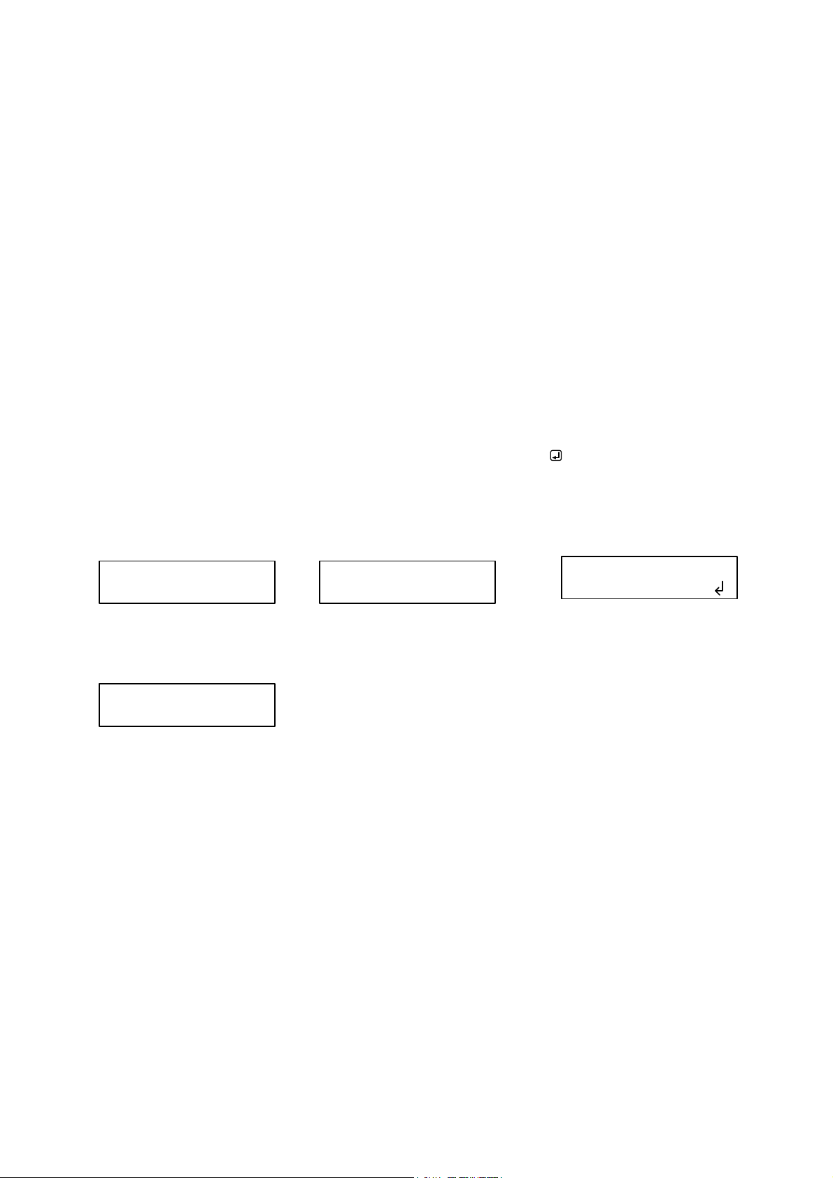
MSD-701UHD / 702UHD / 801UHD/ 802UHD User’s Guide
(1) Only control command
(2) Control command (upper)
Reply command (lower)
(3) Received data is displayed.
SEND:SCREEN UP SEND:SCREEN UP
RECV:SCREEN OK
SEND:PROJECTOR LAMP
RECV:%1LAMP=1000 1
SEND:SCREEN UP
RETRY OVER ERROR
(4) Reply command cannot be
received and a retry error occurs.
■ Con trol command via RS-232C / LAN communication
Control commands can be sent from MSD’s RS-232C connector, LAN connector, or HDB aseT output
connector.
Before executing c ontrol command, set the operati on m ode of t he connect or to “TRANSMITTER”.
【See: 9.11.2 RS-232C operation mode】
【See: 9.12.2 LAN operation mode】
■ Screen display during control command execution
When a control command is executed, the user setting for the text of “MEMO” is displayed (1), and if the reply
command is received, the “MEMO” text regi ster ed for the reply command is also displayed (2) for one second
(when the control command that is used for checking the reply command is executed).
The received data is displ ay ed ( 3) for two seconds (when the control command that is used f or di spl ayi ng the
received data is executed).
Examples:
(1) “SCREEN UP” is registered in MEMO and the control command is executed.
(2) A reply command, “SCREEN OK”, is displayed.
(3) “PROJECTOR LAMP” is registered in t he MEMO and “%1LAMP=1000 1
(4) Reply command could not be r ec eiv ed and r etry over occ ur s.
” is received.
If you configure several control commands, or if you display data received from sever al com ports, the display
time may be shortened by one to two seconds while control commands are being succes sively executed. If
the received data does not fi t in the full screen, the displayed dat a is scrol led.
[Fig. 9.26] Screen display
97
Page 98
MSD-701UHD / 702UHD / 801UHD/ 802UHD User’s Guide
9.13.1 Registering/editing control command
Menu Top→PRESET COMMAND→COMMAND EDIT
Setting for Each command
Setting value [Table 9.21] Setting items of control c ommand
You can create and edit up to 32 control c ommands.
The setting of this menu is not updat ed until the MENU/SET key is pressed. Make sure to press the
MENU/SET key to update the setti ng.
[Table 9.21] Settin g it e m s of c ont rol command
Item
PORT yes yes yes Select “COM”, “CC” or “ CE C”. COM: Communication
COM SIZE yes no no Set th e numb er of bytes to be s ent start ing
DELAY yes yes yes Set the wai t ing t i me of the co ntrol
Communication
port
COMMAND
INPUT MODE
Send command
data
COM CC CEC
Setting
with the f ir st byte.
comman d. Use this i tem for d evices such
as projectors that requires time to cool
down after powering off.
yes no no Set the following communication ports to
“OFF” (not sending communication
commands) or “ON” (sending
communication commands). Those ports
can be set separately, and communication
comman ds can be sent to multiple
communication ports at the same time.
・RS:RS-232C
・OUT1B RS: RS-232C of OUT1B
・OUT2B RS: RS-232C of OUT2B
・LOOP BACK: Internal loop back
・LAN1 to LAN8: LAN con nection 1 to 8
yes no no Set the input mode of send command data.
Select “ASCII” if “DATA” of “COMMA ND ”
consists of only 0A, 0D, and 20 to 7D of
ASCII codes. Select “HEX” if “DATA” of
“COMMAND” includes other codes.
yes no no Set the command f rom the first byte
according to the number of bytes set in
“COM SIZE” (up to 30 bytes).
Description Range
command [Default]
CC: Contact closure
CEC: HDMI CEC control
0BYTE to 30BYTE
[Default] 0BYTE
0ms to 999 s99 9ms
[Default] 0ms
OFF [Default]
ON
*5
*6
ASCII [Default]
HEX
0A, 0D, 20 to 7D in ASCII,
00 to FF in hex
[Default] 20 (space)
98
Page 99
MSD-701UHD / 702UHD / 801UHD/ 802UHD User’s Guide
Setting
COM
CC
CEC
*1
*3 *4
*3 *4
*3 *4
*3 *4
Set w heth er the next command is executed
or not if no response is replied from the sink
device that is controlled with CEC.
Register a note up to 14 characters.
[Table 9.22] Setting items of control command (Cont’d)
Item
Description Range
RECV DISPLAY yes no no Set whether received data is displayed or
not.
DELIMITER
yes no no Set the delimiter to be sent at the end of the
received data.
“NONE”: delimiter is not checked and all
received data within the set timeout will be
valid.
Value other than “NONE”: delimiter is
checked and data received befo re delim i ter
will be valid.
RCV CHECK*2 yes no no Set whether reply command that may be
returned is checked or not.
TIME OUT
yes no no Set the timeout time for reply command to a
sent comman d.
RETRY
yes no no Set the n umber of retries to r esend the
same command again if no valid response
is replied.
INTERVAL
yes no no Set the retry interval to resend the
command.
ERROR
yes no no Set whether t he next command is to be
executed or not if no valid response is
replied, even after completing retry for the
set numb er of r etri es.
Contact closure
control
no yes no Set the contact closure control.
If you select “toggle operation”, it can invert
the condition of contact (open/close).
Pulse width no yes no Set the tim e of returni ng its ori ginal
condition when you control the contact
closure.
HDMI CEC
*7
control
no no yes Set the CEC control for the sink devices
connected to OU T1A / OUT2A / OU T 1 B /
OUT2B.
Process for CEC
no no yes
error
OFF [Default]
ASCII
HEX
NONE [Default]
00 to FF (Hex)
CHECK
NOT CHECK [Default]
0ms to 99s999ms
[Default] 0ms
0 to 99 (times )
[Default] 0
0ms to 99s999ms
[Default] 0ms
STOP [Default]
EXEC: continue
-: not control [Default]
OFF: contact open
ON: contact close
TGL: toggle
NONE: eternity [Default]
100ms to 9990ms (by
10ms)
-: not control [Default]
POWER OFF
POWER ON
STOP [Default]
EXEC: continue
MEMO yes yes yes
The regi stered n ote is display ed when the
control command is executed.
20 to 7D in ASCII codes
except for 2C (,)
[Default] 20 (space)
99
Page 100

MSD-701UHD / 702UHD / 801UHD/ 802UHD User’s Guide
*1 If you set “RECV DISPLAY” to “OFF”, you cannot set this item.
*2 If you set “RECV DISPLAY” to “ASCII” or “HEX”, you cannot set this item .
*3 If you set only “LOOP BACK” of communication ports to “ON”, you do not need to set this item .
*4 If you set all “RCV CHECK” to “NOT CHECK”, you do not need to set t his item .
*5 If y ou set “RS: RS-232C” to “ON”, set “9.11.2 RS-232C operation mod e” to “TRANSMITTER”.
*6 If you set any LAN connections for “LA N1” to “LA N8” to “ON”, set “9.12.2 LAN operation mode” to
“TRANSMITTER”.
*7 CEC: only power ON/OFF of the sink device can be controlled.
■ Setting loop back function
The MSD sends a communication c ommand back to t he MSD it self usi ng the loop back function. It replies
“OK” if processed normally while r eplying “NG” if parameter or command is incorrect. To check the reply
command, set repl y command 31 and 32 to “CHECK”.
■ Setting PJLink
The MSD supports PJLink, whic h is a standard protocol to control pr ojec tors.
To use PJLink, select the LAN connector for “COM port” so that you can select P J Link command when
entering the send comm and data.
【See: 9.12.2 LAN operation mode】
100
 Loading...