

Page 1
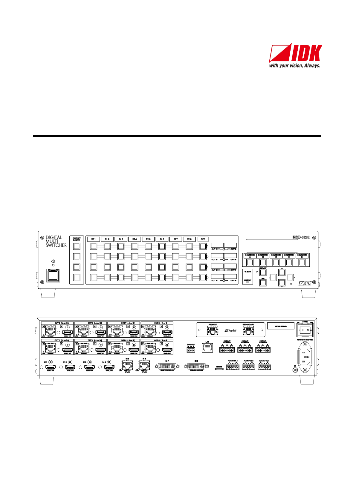
4K@30 supported Digital Multi Switcher
MSD-62 series
MSD-6203 / MSD-6204 / MSD-6206 / MSD-6208
<Command Reference Guide>
Ver.1.0.1
Thank you for choosing this IDK product.
To ensure the best performanc e of this product, please read this User’s Guide fully and carefully
before using it and keep t his manual beside this product.
IDK Corporation
Page 2

MSD-62 series Command Guide
Trademarks
The terms HDMI and HDMI High-Defi nition Multimedia Interface, and the HDMI Logo are trademarks or
registered tradem ar k s of HDM I Licensi ng A dm inistrator, Inc. in the Unit ed S tates and other countries.
PJLink is a trademar k in Japan, the Unit ed S tates, and other countries/regions.
All other company and product names mentioned in this manual ar e either r egistered trademark s or
trademark s of their r espect ive owners. In this manual, the “®” or “™” marks may not be specified.
2
Page 3

MSD-62 series Command Guide
Before reading this manual
● All rights reserv ed.
● Some of the contents i n this command guide such as product appearance i n diagr ams, menu operations,
communicati on c ommands, and so on m ay differ from one NJR-CTB model to another.
● This command guide i s subject to change without notice. Y ou c an download the latest version fr om IDK ’s
website at: http://www.idkav.com
The reference manual for the NJR-T01UHD/NJR-R01UHD consists of the two following v olum es:
■ User’s guide: Pl ease download from the website above.
■ Command guide (this document): Please download f r om the website above.
3
Page 4

MSD-62 series Command Guide
Table of Contents
1 About this Guide ................................................................................................................................... 5
2 Communication c onfiguration and Specifi c ations .................................................................................. 6
2.1 RS-232C communication ................................................................................................................. 6
2.1.1 RS-232C connector specification .............................................................................................. 6
2.1.2 RS-232C communication specificati on...................................................................................... 6
2.1.3 Setting up RS-232C comm unic ation ......................................................................................... 7
2.2 LAN communication ........................................................................................................................ 8
2.2.1 LAN connector specification ..................................................................................................... 8
2.2.2 LAN communication specification ............................................................................................. 8
2.2.3 Setting up LAN communi c ation................................................................................................. 9
2.2.4 The number of TCP-IP connections .........................................................................................11
3 Command ...........................................................................................................................................12
3.1 Command outline ...........................................................................................................................12
3.2 Command list .................................................................................................................................13
3.3 Detailed descriptions ......................................................................................................................18
3.3.1 Error status .............................................................................................................................18
3.3.2 Power status ...........................................................................................................................19
3.3.3 Input channels .........................................................................................................................19
3.3.4 Position, size, and masking .....................................................................................................21
3.3.5 Video processing.....................................................................................................................33
3.3.6 Image quality...........................................................................................................................35
3.3.7 Input setti ngs...........................................................................................................................40
3.3.8 Input timing .............................................................................................................................45
3.3.9 Output settings ........................................................................................................................52
3.3.10 Audio ......................................................................................................................................62
3.3.11 EDID .......................................................................................................................................70
3.3.12 RS-232C communication .........................................................................................................77
3.3.13 LAN communication ................................................................................................................81
3.3.14 Control commands ..................................................................................................................85
3.3.15 Preset memory ......................................................................................................................100
3.3.16 Bitmap ..................................................................................................................................106
3.3.17 Other settings ........................................................................................................................113
4
Page 5

MSD-62 series Command Guide
1 About this Guide
This guide cont ains the pr oc edur e for controlling the MSD-62 series using commands via RS-232C
communicati on or LAN communication.
■ You can perform the following oper ations using communication commands.
・Switching channels.
・Setting I/O, audio, and E DID.
・Setting sending of exter nal control command.
・Setting preset memory.
・Setting and displaying bitmaps
and others
5
Page 6
MSD-62 series Command Guide
Tx
Rx
GND
RS-232C T x
RS-232C Rx
GND
U p to 0.28" (7 mm)
Standard
RS-232C
Data bit length [bit]
7 / 8
Parity check
NONE, EVEN, ODD
Stop bit [bit]
1 / 2
X parameter
Invalid
Flow control
None
Delimiter
CR LF (Carriage retur n and line feed, 0D and 0A in hex)
Communication method
Full duplex
2 Communication configuration and Specifications
2.1 RS-232C commu ni ca tio n
2.1.1 RS-232C connector specification
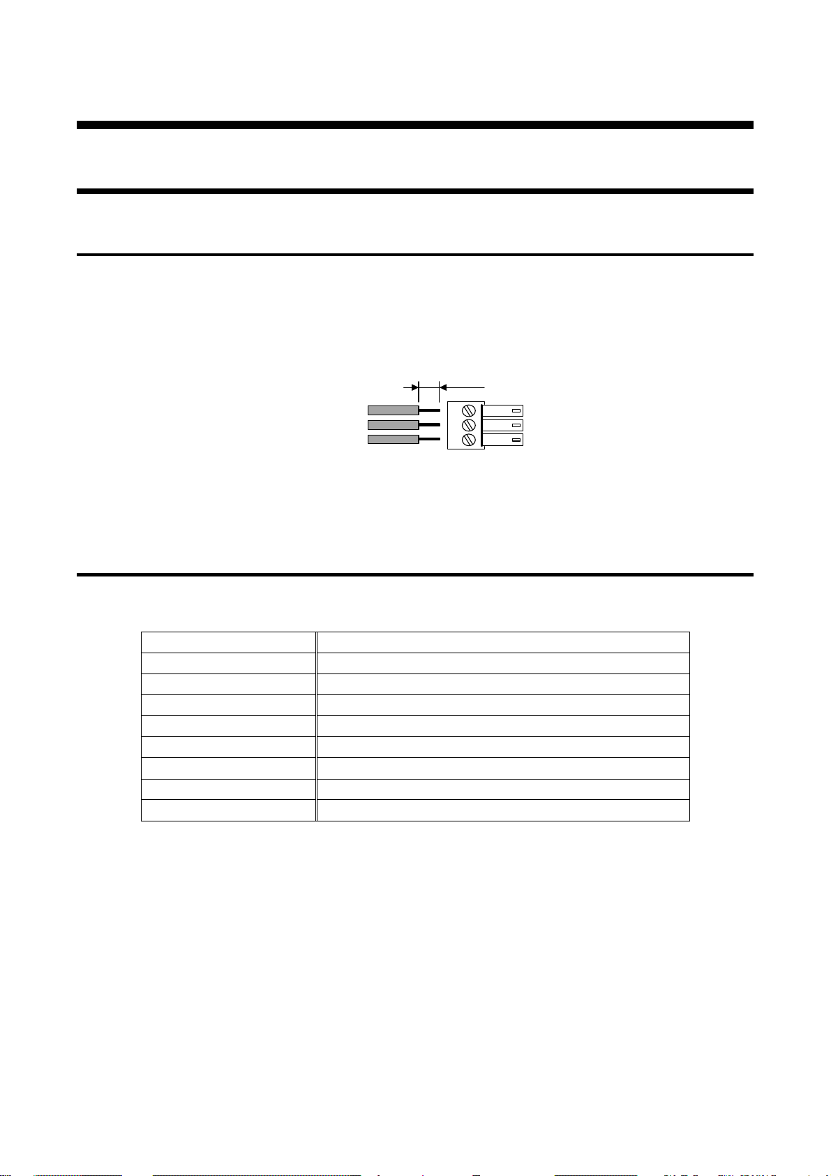
Connect an RS-232C cable to the provided 3-pin terminal block and then insert the 3-pin terminal block into to
the appropriat e por t on t he MSD’s rear panel.
AWG28 to AWG16 conductor gauge is recommended. The recomm ended wir e stri p length is 0.28 in. (7 mm).
If it is connected to a D-sub9 pin, cut RTS, CTS, DTR, and DSR (unused) as needed.
[Fig. 2.1] Connecting RS-232C cable to 3-pin terminal block connector
2.1.2 RS-232C communication specification
[Table 2.1] RS-232C specification
Baud rate [bps] 4800 / 9600 / 19200 / 38400 [bps]
6
Page 7
MSD-62 series Command Guide
Step (2)
Step (1)
RS-232C cable
Step (4)
Communication
command
Step (3)
Laptop
(Controller)
Laptop
Projector
RS-232C cable
RS232C cable
Communication
Command to MSD
Output control
Command to external
device
2.1.3 Setting up RS-232C communication
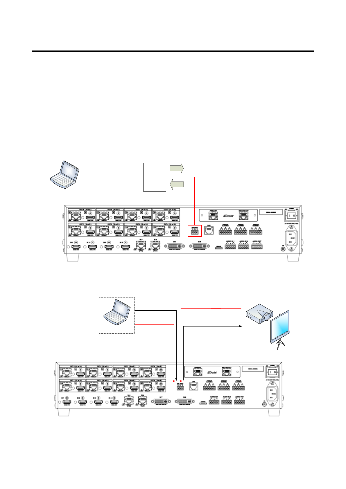
(1) Connect the MSD and the contr ol dev ic e v ia an RS-232C cabl e.
(2) Set the RS-232C communic ation as follows:
・RS-232C communication: Baud r ate, data bit length, parity check, and stop bit
・Operation mode of RS-232C communication: “RECEIVER”
【Reference: User’s Guide】
(3) For the control dev ic e, set t he same values in the same way as RS-232C communicati on (baud rat e, data
bit length, parit y c hec k, and stop bit) in step (2) above.
(4) Send a communication command from the control device to the MSD in order to check the control status of
the MSD.
[Fig. 2.2] Setting RS-232C communication (Example: MSD-6208 with Dante)
■ Operation exampl e of RS-232C commun ication
[Fig. 2.3] RS-232C communication (Example: MSD-6208 with Dante)
7
Page 8
MSD-62 series Command Guide
81
LAN connector
8-pin RJ -45 connector
(Rear panel)
Lights in green while link is established.
Blinks in green while data is being sent/received.
Lig ht s in orange i f t he sen d/rece ive rate is 100 Mbps.
Goes off if it is 10 Mbps.
RX+: Received Data+
N.C : Not connected
TX+: Transmitted Data+
Pin #
1
3
2
4
6
5
7
Signal Name
TX- : Transmitted Data N.C : Not connected
RX- : Received Data-
N.C : Not connected
N.C : Not connected
MDI
TX+ : Transmitted Data+
N.C : Not connected
RX+: Received Data+
RX- : Received Data-
N.C : Not connected
TX- : Transmitted Data-
N.C : Not connected
N.C : Not connected
MDI-X
8
Network layer
ARP, IP, ICMP
Port used for WEB browser control (HTTP): 80, 5000 to 5999
Application layer
HTTP, TEL N ET
2.2 LAN communication
2.2.1 LAN connector specification
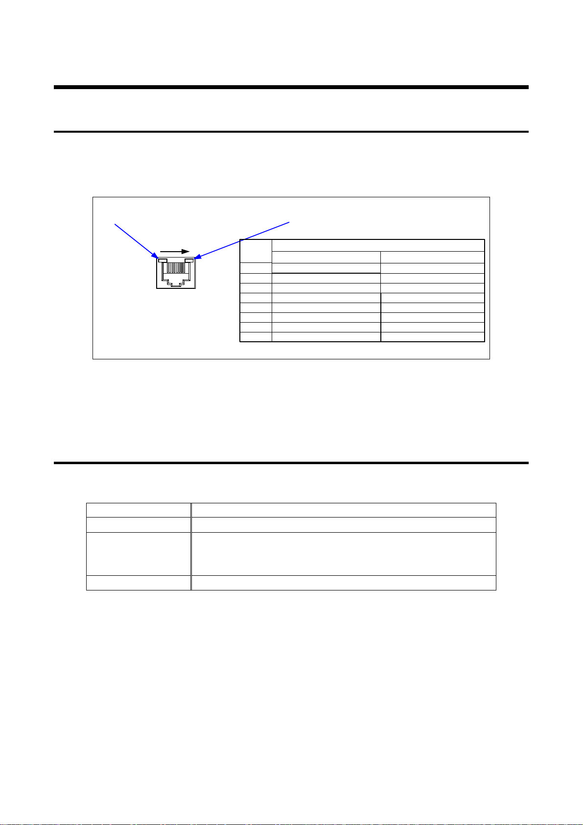
It supports Auto MDI/M DI-X, which distinguishes/swit c hes straight and cross cables automatically.
Pin assignment s of LA N connect or :
[Fig. 2.4] LAN connector
2.2.2 LAN communication specification
[Table 2.2] Specification o f LAN communication
Physical layer 10Base-T (IEEE802.3i) / 100Base-TX (IEEE802.3u)
TCP
Transport layer
Note: Up to 8 connections can be used simultaneously.
Port used for command control: 23, 1100, 6000 t o 6999
8
Page 9
MSD-62 series Command Guide
Step (3)
Laptop
Step (2)
Step (1)
LAN cable
Step (4)
Communication
command
(Controller)
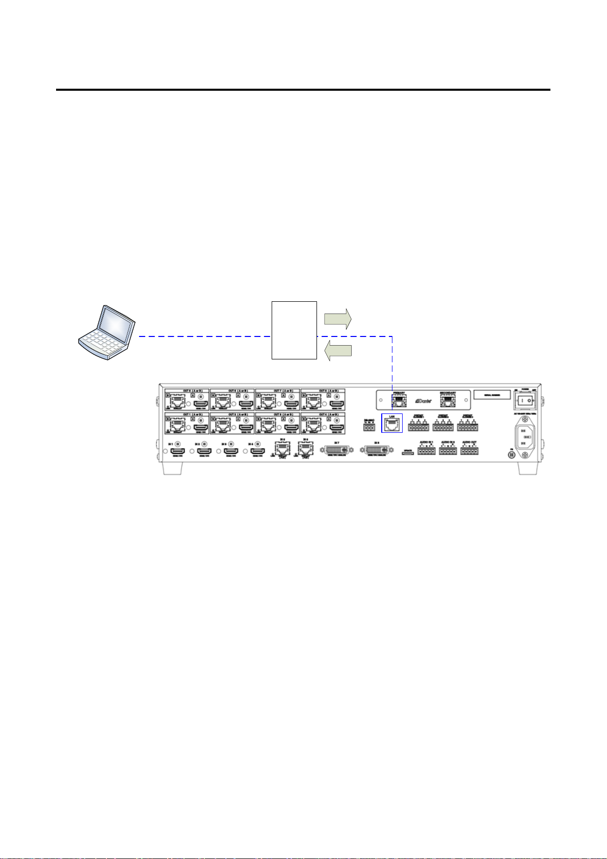
2.2.3 Setting up LAN communication
(1) Connect the MSD and the cont r ol dev ic e vi a a LAN cable.
(2) Set up LAN communication as follows:
・Set IP address and subnet mask
・Operation mode of LAN communi c ation: “RECEIVER”
・TCP pot number: 23, 1100, 6000 t o 6999
【Reference: User’s Guide】
(3) Establish the connecti on from the control device to the IP address and TCP port that are set to the
MSD in step (2) above.
(4) Send a communication command from the control device to the MSD in or der to c hec k the contr ol
status of the MSD.
[Fig. 2.5] Setting LAN communication (E xampl e: MSD-6208 wi th Dante)
9
Page 10
MSD-62 series Command Guide
Laptop
Projector
LAN cable LAN cable
Power amp.
Communication
Command to MSD
Outputs control command
to external device
Outputs control command
to external device
Communication
Command to MSD
Switching hub
LAN cable
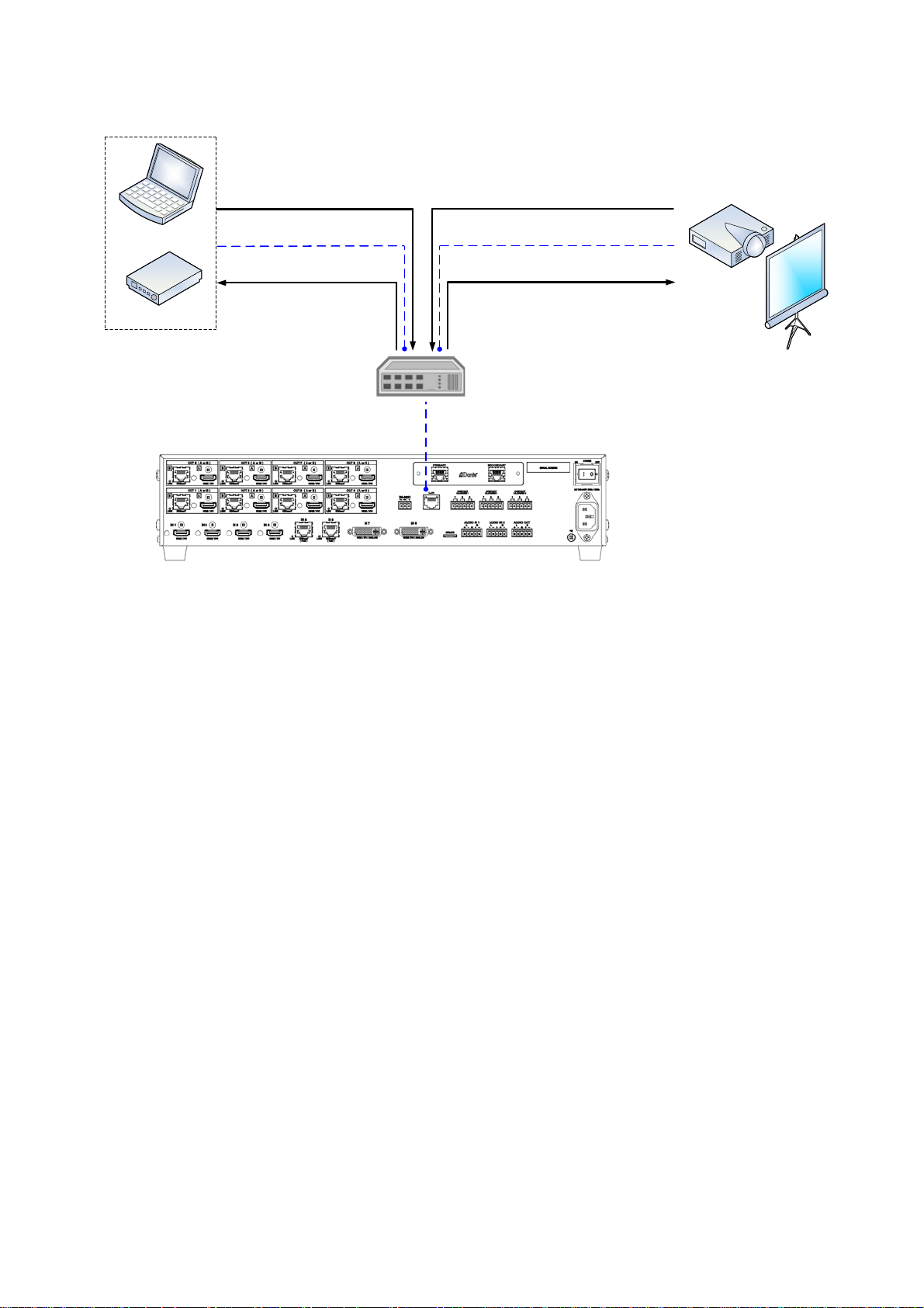
■ Operation example of LAN communication
[Fig. 2.6] Example of LAN communication (Example: MSD-6208 with Dante)
10
Page 11
MSD-62 series Command Guide
Your PC software
Send command (@xxx)
(@xxx)
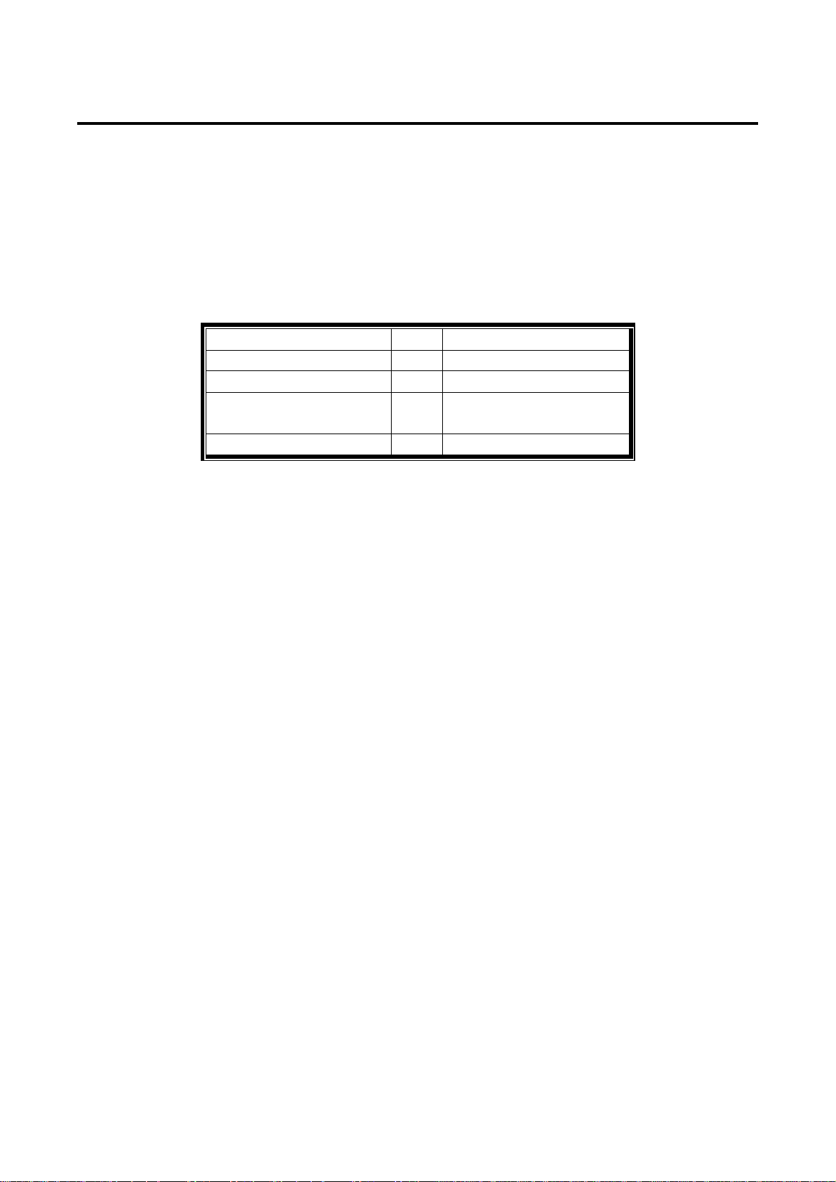
2.2.4 The number of TCP-IP connections
The MSD series can connect up to eight connections (eight ports) simultaneously. If the MSD is contr olled
from nine or more PCs, they may not be connected to the MSD normally, since the number of connec tions
that can be used is limited.
If you use nine connections or more, execute TCP-IP connecti on/close every time the communic ation
command is sent or received from the software of user’s side. By doing so, MSD’s ports are occupied or
released so that nine or m or e connect ions can be connected logically.
[Table 2.3] Increasing connections
MSD
TCP-IP connection → (Occupied by 1 port)
→
← Send back command
TCP-IP close → (Release 1 port)
Note: If any command is not sent from the PC side to the MSD for 30 seconds, the MSD di sconnec t s the
connection t o av oid the limitation problem on the num ber of connec tions. As a result, connection needs to be
established again f r om the PC si de aft er the cur r ent connection of the PC is disconnected.
(Since the number of port s i n the MDS is eight , ports are occupied permanently if the PC is turned off while
connections are valid. To prevent this, the MSD disconnects connec t ions if no communicati on c ommand is
sent from the PC side.)
11
Page 12
MSD-62 series Command Guide
3 Command
3.1 Comma nd o utl i n e
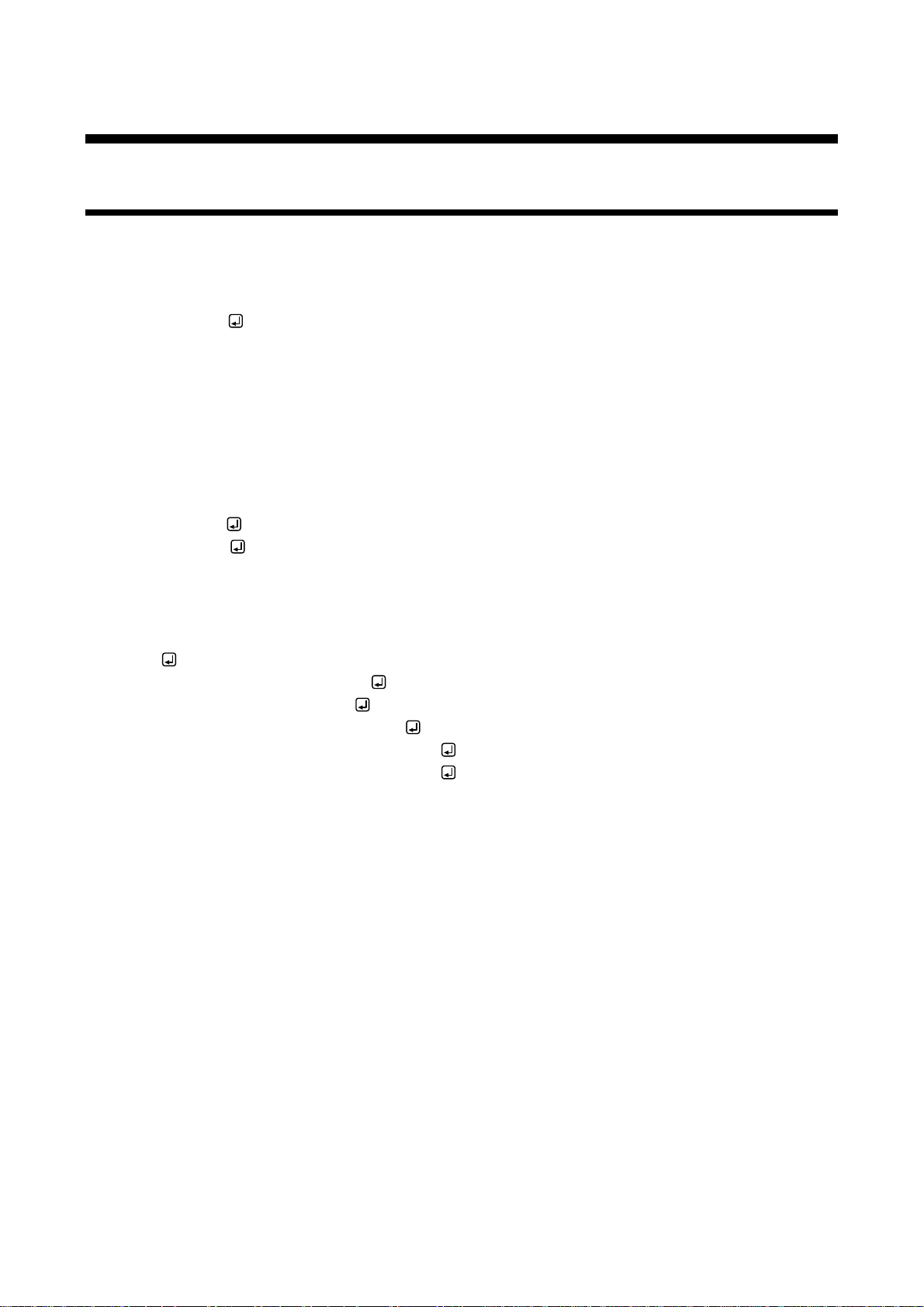
A command consists of “@” (“40” in hexadecimal), 3 one-byte alphabetical character s (upper and lower
cases), and parameters (one-byte numbers
no parameter is required. Processing is execut ed by sendi ng a delim iter at the end of the command.
Example: @SPM,2
“,”( a comma, “2C” in hexadecim al) is indicated between a command and param eter and between two
parameters.
■ If there is an error:
An error command is returned if an undefined command or wrong parameter is included.
Example: @SOT,1
@ERR,1
■ Using as HELP
If only delimiter is sent, c ommand list as the help command is returned.
Example:
--------------- HELP (1/14) ---------------
(CHANNEL SELECT Command)
@GSW / @SSW : Get/Set Input Channel
@GSV / @SSV : Get/Set Video Input Channel
@GSA / @SSA : Get/Set Audio Input Channel
*
). For some commands, several par am eters can be specified or
12
Page 13
MSD-62 series Command Guide
@ERR
Error status
18
Command
Function
Page
@GSV / @SSV
Switching video channel
20
Command
Function
Page
@GOT / @SOT
Output resolution
21
@GTD
Actual output r esol ution
22
@GUM / @SUM
Aspect ratio of sink dev ic e
23
@GAP / @SAP
Aspect ratio
23
@GOV / @SOV
Overscan
24
@GTP / @STP
Test pattern
32
3.2 Comma nd li s t
■ Error status
Command Function Page
■ Power status
Command Function Page
@GPS / @SPS Standby button 19
■ Input channels
@GSW / @SSW Switching video and audio channel simultaneousl y 19
@GSA / @SSA Switching audio channel 20
■ Position, size, and masking
@GAR / @SAR Aspect ratio restoration 24
@GNP / @SNP Input position 25
@GNS / @SNS Input size 26
@GNM / @SNM Input masking 27
@IAS Input automati c sizing 27
@GOP / @SOP Output positi on 28
@GOS / @SOS Output size 29
@GOM / @SOM Output masking 30
@OAS Output autom atic si zi ng 30
@GBC / @SBC Background color 31
13
Page 14
MSD-62 series Command Guide
Command
Function
Page
@GOR / @SOR
Video processing m ode
33
@GOI / @SOI
Flip horizont al
34
Command
Function
Page
@GFL / @SFL
Sharpness
35
@GBR / @SBR
Input brightness
35
@GHU / @SHU
Hue
36
Command
Function
Page
Command
Function
Page
@AIS / @AIT
Automatic measurement
45
@GTK / @STK
Tracking
51
■ Video proc e s s ing
@GPR / @SPR Window display priority 33
@GWV / @SWV Hiding window 34
■ Image quality
@GCO / @SCO Input contrast 36
@GST / @SST Saturation 37
@GSU / @SSU Blac k level 37
@IDC Input default c olor 38
@GOB / @SOB Output bright ness 38
@GOC / @S OC Output contrast 39
@GGM / @SGM Output gamma 39
@ODC Output default color 40
■ Input settings
@GDT / @SDT No-signal-input monitoring 40
@GHE / @SHE HDCP input enabled/disabled 41
@GAI / @SAI Analog input t y pe 41
@GID / @SID Automatic detection of input video interruption 42
@GIN / @SIN Signal selection of DVI input connector 42
@GIA / @SIA HDBaseT input long reach mode 43
@GFX / @SFX Fixing settings for input signal 44
■ Input timing
@GHT / @SHT The total number of horiz ontal dots 46
@GHS / @SHS Horizontal start posi tion 47
@GHD / @SHD Horizontal display period 47
@GVS / @SVS Vertical star t position 48
@GVD / @SVD Vertical display period 48
@GIS / @SIS Automatic measurem ent of start posi tion 49
@GSM / @SSM Aut om atic measurement when unregistered si gnal is input 49
@RTT Loading device data 50
@STT Registering device data 50
14
Page 15
MSD-62 series Command Guide
Command
Function
Page
@GEQ / @SEQ
Output equalizer
52
@GUY / @SUY
Synchronous signal output when no video signal is input
53
@GDC / @SDC
Deep Color
58
@HAU
HDCP re-encryption
59
@GAU / @SAU
Priority of input channel automatic switching (OFF to ON)
59
@GOF / @SOF
Priority of input channel automatic switching (ON to OFF)
60
@GMT / @SMT
Masking time after automatic switching of i nput channel
60
@GAD / @SAD
Channel switching mode for input channel automatic switching
61
@GOA / @SOA
HDBaseT output long r eac h m ode
61
Command
Function
Page
@SOL
Relativ e value of audio output level
62
@GOL
Limit status of audio output level
63
@GAM / @SAM
Audio output mute
63
@GAS / @SAS
Selecting audio input
64
@GSO / @SSO
Aduio input level
65
@SIL
Relative value of audio input level
65
@GIL
Limit status of audio input level
65
@GLO / @SLO
Output lip sync
66
@GLY / @SLY
Input lip sync
66
@GSF / @SSF
Sampling frequency
67
■ Output settings
@GDM / @SDM Output mode 52
@GBO / @SBO Output video when no video signal i s not input 53
@GFF / @SFF Video switching effect 54
@GFT / @SFT Video switching speed 54
@GWC / @SWC Wipe col or 55
@GVO / @SVO HDMI / HDBaseT output 56
@GEN / @SEN HDCP output 57
@GHR / @SHR The number of HDCP ret ri es 57
@GCE / @SCE CEC connec tion 58
■ Audio
@GSL / @SSL Audio output level 62
@GFD Actual sampling frequency 67
@GCS / @SCS Analog audi o output 68
@GMD / @SMD Multi channel audio output 68
@GAT / @SAT T est tone 69
15
Page 16
MSD-62 series Command Guide
Command
Function
Page
@GED / @SED
EDID
70
@GHF / @SHF
Input resolution for AV devices
72
Command
Function
Page
@GCT / @SCT
RS-232C communication
77
Command
Function
Page
@GIP / @SIP
IP address
81
@GSB / @SSB
Subnet mask
82
@GGW / @SGW
Gateway address
82
Command
Function
Page
@EXC
Executing control commands
85
@GDS / @SDS
Power button of sink devic e
85
@GEC / @SEC
Control command (Comm unic ation command)
86
@GEC / @SEC
Control command (contact closure)
90
■ EDID
@GVF / @SVF Input resolution for PC 71
@GDI / @SDI Deep Color input 73
@GAF / @SAF Audio format 74
@GSP / @SSP The number of speakers (cont’d) 76
@RME Copying EDID 76
■ RS-232C communication
@GCF / @SCF RS-232C communication mode 78
@GCI / @SCI RS-232C transmission 79
@GCQ / @SCQ RS-232C HDBaseT sending channel 80
@GCR / @SCR RS-232C HDBaseT receiving channel 80
■ LAN communication
@GLF / @SLF LAN communication mode 83
@GLP / @SLP TCP port number 84
@GMC MAC address 84
■ Control commands
@GEC / @SEC Control c ommand (Displaying received dat a) 88
@GEC / @SEC Control c ommand (CE C) 91
@GRC / @SRC Response command 92
@GCC / @SCC Control c ommand link 93
@GTG / @STG Toggle operation 96
@GUP / @SUP Plane to be executed when powered ON 96
@GIT / @SIT Ineffective time during control command exec ution 97
@DEC Initializing registered command and link 97
@GTL / @STL Lighting condition of execution button 98
@GTF / @STF Blinking time of sink dev ic e power swit c h 99
16
Page 17
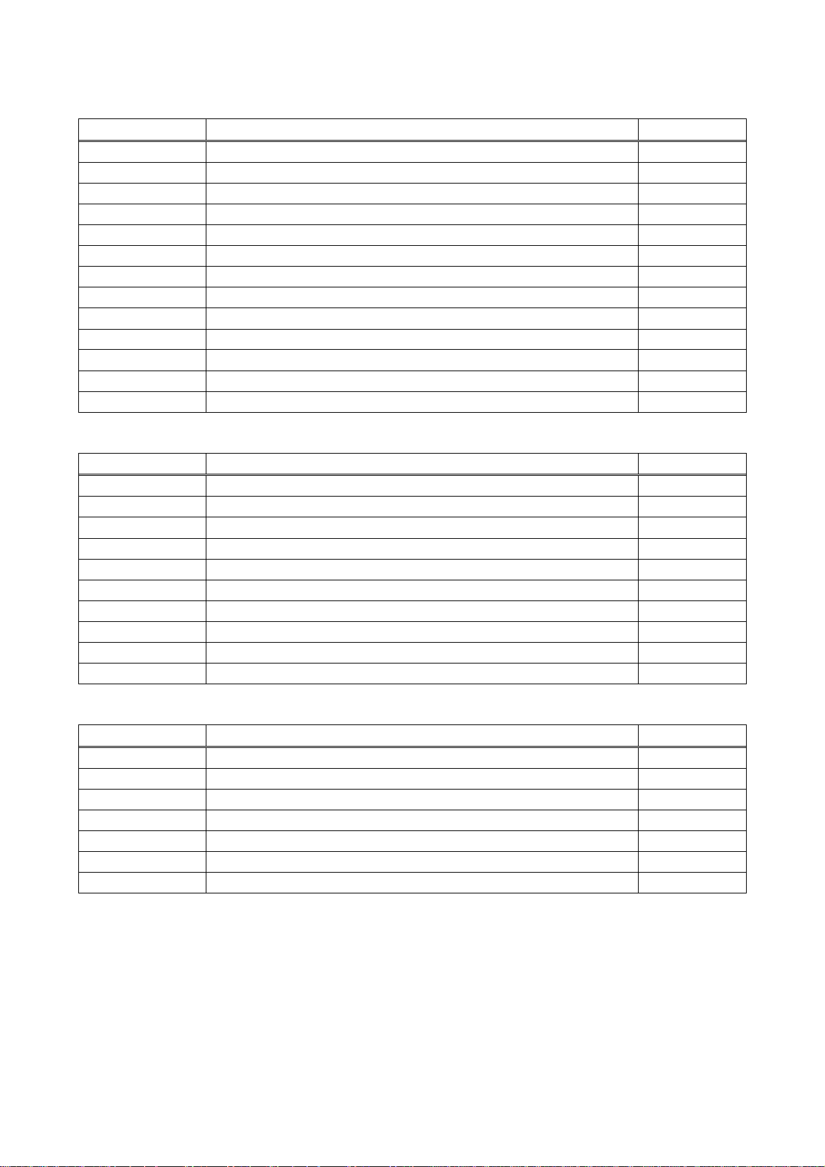
MSD-62 series Command Guide
Command
Function
Page
@RCM
Loading crosspoint memory
100
@GCM / @ECM
Editing crosspoint memory
101
@SPM
Saving all settings
105
@GMU / @SMU
Startup settings
106
@GBA / @SBA
Assigning input c hannel
110
@GBD / @SBD
Dividing memory area
111
@GBV
Memory area status
111
@GFZ / @SFZ
Freeze
112
@CAP
Capturing input image
112
@GLM / @SLM
Setting operation to be locked
113
@GBZ / @SBZ
Buzzer
114
@GHP / @SHP
Power supply of HDBaseT input
114
@GSS
I/O status
115
@GES
Monitor’s EDID
119
@GIV
Version
119
■ Preset memory
@SCM / @SEM Saving channels to crosspoint memory 100
@RCV Loading crosspoint memory (sett ing video channel) 101
@SCV / @SEV Saving c r osspoint m em or y (Sett ing video channel) 102
@GCV / @ECV Editing crosspoint mem or y (Sett ing video channel) 102
@RCA Loading audio channel setting from crosspoint memory 103
@SCA / @SEA Saving c r osspoint m em or y (Sett ing audio channel) 103
@GCA / @ECA Editing crosspoint mem or y (Sett ing audio channel) 104
@RPM Loading all settings 104
@SCP Copy ing output setting 105
■ Bitmap
Command Function Page
@GBM / @SBM Outputting bitmap im age 106
@GBB / @SBB Background color 107
@GBT / @SBT Aspect r atio 108
@GZP / @SZP Display position 109
@GPB / @SPB Start up bitmap 110
■ Other settings
Command Function Page
@GLS / @SLS Operation lock 113
17
Page 18
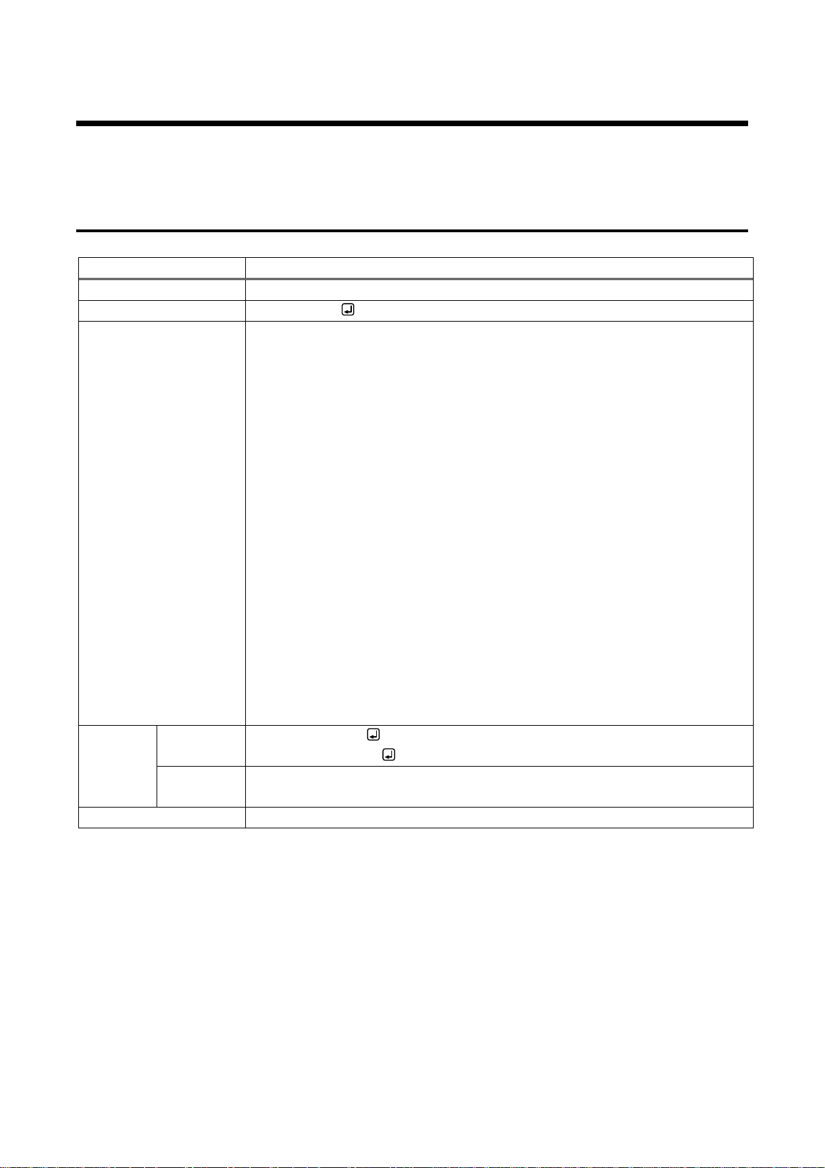
MSD-62 series Command Guide
@ERR
Error status
Response
@ERR, error
example
Response
Response @ERR,2
Description
@IOS is sent.
3.3 Detailed descr i ptions
Command formats for MSD-6280 are shown in this section. For other m odels, use each appr opr iate
command formats according to the number of outputs.
3.3.1 Error status
Description Response in case the comm and is not ex ec uted.
Parameter error: Error status
1 = Erroneous parameter format or value
2 = Undef ined command or wrong form at
3 = Curr ently cannot be used.
4 = Not used.
5 = T he c ommand could not be executed, because the c ontrol c ommand
was not registered.
6 = The command could not be processed since another command was
being executed.
7 = Automatic measurem ent of i nput timing failed.
8 = Loading EDID from the sink device failed.
9 = Not used.
10 = The control command was stopped according to the stop conditi on.
11 = T he c ontrol command was stopped since the number of retries
exceeded the set value of “RE TRY”.
12 = The c ontrol command of PJLink was stopped since t he password di d
not match.
13 = The image could not be captured since the image size to be captured
exceeded the reserved memory size.
14 = Capturing input image failed.
Getting
Command
Command @IOS
Remarks -
18
Command format error.
Page 19
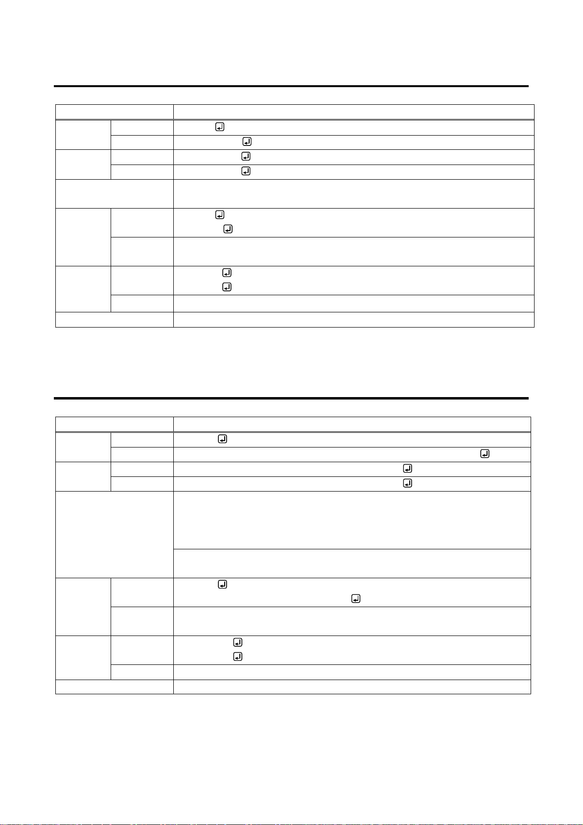
3.3.2 Power status
@GPS / @SPS
Standby button
Getting
Command
@GPS
Response
@GPS, onoff
Command
@SPS, onoff
Response
@SPS, onoff
0 = OFF (Standby), 1 = ON (Power on)
It is powered on.
Setting
Command
@SPS,1
Remarks
@GSW / @SSW
Switching video and audio channel simultaneously
Response
@GSW, video_1, audio_1, video_2, audio_2,
, video_8, audio_8
Setting
Command
@SSW, input_1, output_1 (, input_2, output_2
)
Response
@SSW, input_1, output_1 (, input_2, output_2
)
Parameter
video_1-8 : Video input channel
0 = All outputs, 1 = OUT1 to 8 = OUT8
example
Response
@GSW, 2,2,2,2,2,2,2,2,0,0,0,0,0,0,0,0
example
Response
@SSW,1,1
Description
Setting IN1 video and audio to be output to OUT1.
Remarks
Setting
Parameter onoff: Standby but ton
MSD-62 series Command Guide
Getting
example
Description Get ting the standby button status.
example
Command
Response
Response
Description Setting the standby butt on to ON (powered on).
@GPS
@GPS,1
@SPS,1
-
3.3.3 Input channels
Getting Command @GSW
・・・
・・・
・・・
audio_1-8 : Audio input channel
input_1-8 : Video and audio input channel
0 = OFF [Default], 1 = IN1 to 8 = IN8
output_1-8: Video and audi o output channel
Getting
Description Getting the video and audio input channels that are assigned to output channels.
Setting
Command
Command
@GSW
OUT1 to OUT4: IN2, OUT4 to OUT8: OFF
@SSW,1,1
-
19
Page 20
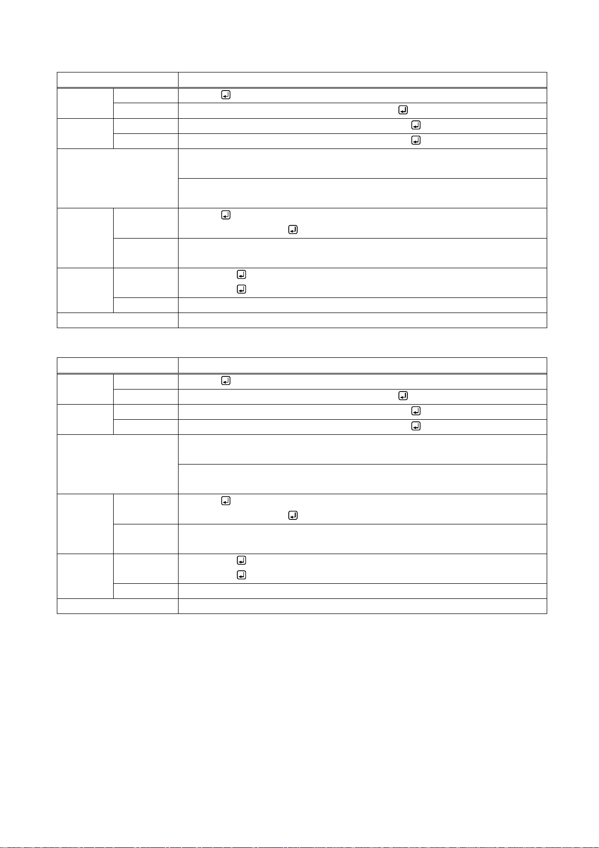
MSD-62 series Command Guide
@GSV / @SSV
Switching video channel
Response
@GSV, input_1, i nput_2, input_3,
, input_8
Response
@SSV, input_1, output_1 (, input_2, output_2
)
Parameter
input_1-8: Video input c hannel
0 = All outputs, 1 = OUT1 to 8 = OUT8
Getting
Command
@GSV
OUT1 to OUT4: IN1, OUT5 to OUT8: IN2
example
Response
@SSV,1,1
Description
Setting IN1 video to be out put t o OUT 1.
Remarks
@GSA / @SSA
Switching audio channel
Response
@GSA, input_1, i nput_2, input_3,
, input_8
Response
@SSA, input_1, output_1 (, input_2, output_2
)
Parameter
input_1-8: Audio input c hannel
0 = All outputs, 1 = OUT1 to 8 = OUT8
Getting
Command
@GSA
OUT1 to OUT4: IN1, OUT5 to OUT8: IN2
example
Response
@SSA,1,1
Remarks
Getting Command @GSV
・・・
Setting Command @SSV, input_1, output_1 (, input_2, output_2・・・)
・・・
0 = OFF [Default], 1 = IN1 to 8 = IN8
output_1-8: Video output channel
example
Response
@GSV,1,1,1,1,2,2,2,2
Description Getting the video I/O channel statuses.
Setting
Command
@SSV,1,1
-
Getting Command @GSA
・・・
Setting Command @SSA, input_1, output_1 (, input_2, output_2・・・)
・・・
0 = OFF [Default], 1 = IN1 to 8 = IN8
output_1-8: Audi o output c hannel
example
Response
@GSA,1,1,1,1,2,2,2,2
Description Getting the audi o I/O c hannel status.
Setting
Command
@SSA,1,1
Description Setting IN1 audio to be output to OUT1.
-
20
Page 21
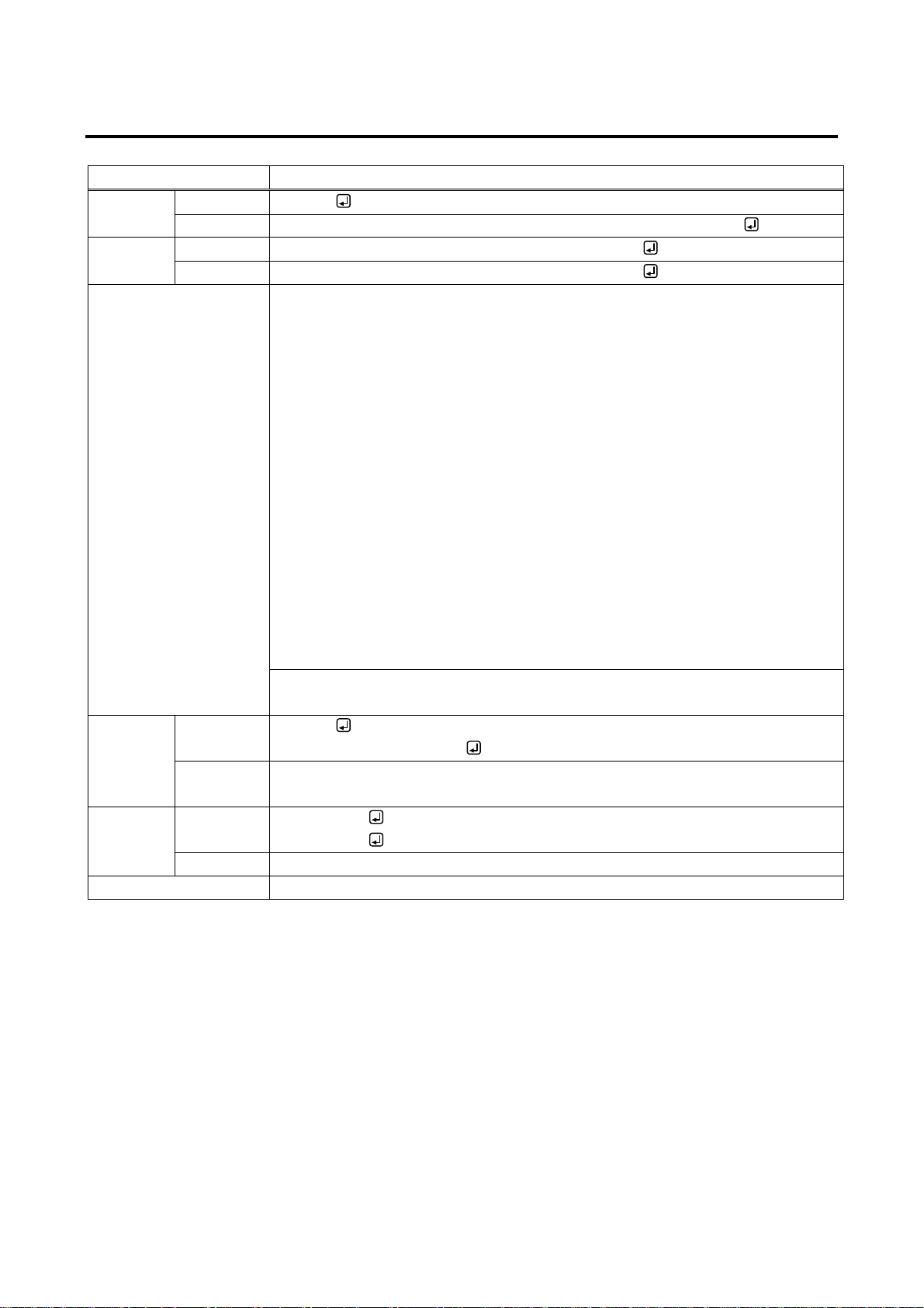
3.3.4 Position, size, and masking
@GOT / @SOT
Output resolution
Getting
Command
@GOT
Response
@GOT, resolution_1, resolution_2, r esol ution_3,
, resolution_8
Command
@SOT, ch_1, resolution_1 (, ch_2, resoluti on_2
)
Response
@SOT, ch_1, resolution_1 (, ch_2, resoluti on_2
)
47 = 2160p@30 (4096x2160)
example
Response
@GOT,7,7,7,7,31,31,31,31
OUT1 to OUT4: SXGA, OUT5 to OUT8: 1080p 59.94 Hz
Setting
Command
@SOT,1,31
Setting
Parameter resolution_1-8: Setting val ue of out put resolution
0 = AUTO [Default], 3 = XGA@60 (1024x768),
4 = WXGA@60 (1280x768), 5 = WXGA@60 (1280x800),
6 = Quad-VGA@60 (1280x960), 7 = SXGA@60 (1280x1024),
8 = WXGA@60 (1360x768), 9 = WXGA@60 (1366x768),
10 = SXGA+@60 (1400x1050), 11 = WXGA+@60 (1440x900),
12 = WXGA++@60 (1600x900), 13 = UXGA@60 (1600x1200),
14 = WSXGA+@60 (1680x1050), 15 = VESAHD@60 (1920x1080),
16 = WUXGA@60 (1920x1200), 17 = QWXGA@60 (2048x1152),
24 = 720p@50 (1280x720), 25 = [email protected] (1280x 720) ,
26 = 720p@60 (1280x720), 27 = 1080i@50 (1920x1080),
28 = [email protected] (1920x 1080) , 29 = 1080i@60 (1920x1080),
30 = 1080p@50 (1920x1080), 31 = [email protected](1920x 1080),
32 = 1080p@60 (1920x1080), 40 = 2160p@24 (3840x2160),
41 = 2160p@25 (3840x2160), 42 = 2160p@30 (3840x2160),
45 = 2160p@24 (4096x2160), 46 = 2160p@25 (4096x2160),
MSD-62 series Command Guide
・・・
・・・
・・・
ch_1-8: Output channel
0 = All outputs, 1 = OUT1 to 8 = OUT8
Getting
Description Getting the set output r esol ution.
example
Description S etting output resol ution of OUT1 to 1080p 59.94 Hz.
Remarks -
Command
Response
@GOT
@SOT,1,31
21
Page 22
MSD-62 series Command Guide
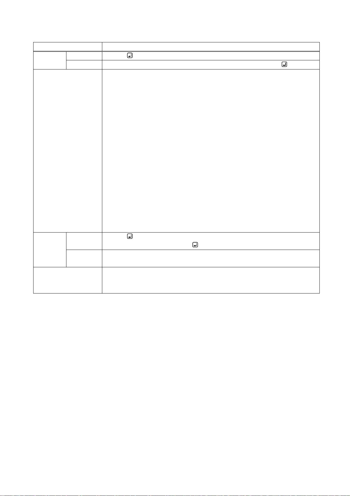
@GTD
Actual output resolution
Response
@GTD, resolution_1, resolution_2, resolution_3,
, resolution_8
example
Response
@GTD,31,31,31,31,26,26,26,26
OUT1 to OUT4: 1080p 59.94 Hz, OUT5 to OUT8: 720p 60 Hz
Remarks
If “@GOT / @SOT Output resolution” is set to “AUTO”, the actual output
other than “AUTO”, the set out put resolution is returned.
Getting Command @GTD
Parameter resolution_1-8: Actual output r esol ution
1 = VGA@60 (640x480), 2 = SVGA@60 (800x600),
3 = XGA@60 (1024x768), 4 = WXGA@60 (1280x768),
5 = WXGA@60 (1280x800), 6 = Quad-VGA@60 (1280x960),
7 = SXGA@60 (1280x1024), 8 = WXGA@60 (1360x768),
9 = WXGA@60 (1366x768), 10 = SXGA+@60 (1400x1050),
11 = WXGA+@60 (1440x900), 12 = WXGA++@60 (1600x900),
13 = UXGA@60 (1600x1200), 14 = WSXGA+@60 (1680x1050),
15 = VESAHD@60 (1920x1080) , 16 = WUXGA@60 (1920x1200),
17 = QWXGA@60 (2048x1152),
21 = [email protected] (720x 480),
23 = 576p@50 (720x576), 24 = 720p@50 (1280x720),
25 = [email protected] (1280x 720) , 26 = 720p@60 (1280x720),
27 = 1080i@50 (1920x1080), 28 = 1080i@ 59.94 (1920x1080),
29 = 1080i@60 (1920x1080), 30 = 1080p@ 50 ( 1920x 1080) ,
31 = [email protected] (1920x1080), 32 = 1080p@60 (1920x1080),
40 = 2160p@24 (3840x2160), 41 = 2160p@25 (3840x2160),
42 = 2160p@30 (3840x2160), 45 = 2160p@24 (4096x2160),
46 = 2160p@25 (4096x2160), 47 = 2160p@30 (4096x2160)
Getting
Command
@GTD
・・・
Description Getting the actual output resolution.
resolution is retur ned. If “@GOT / @SOT Output resolution” is set to the value
22
Page 23
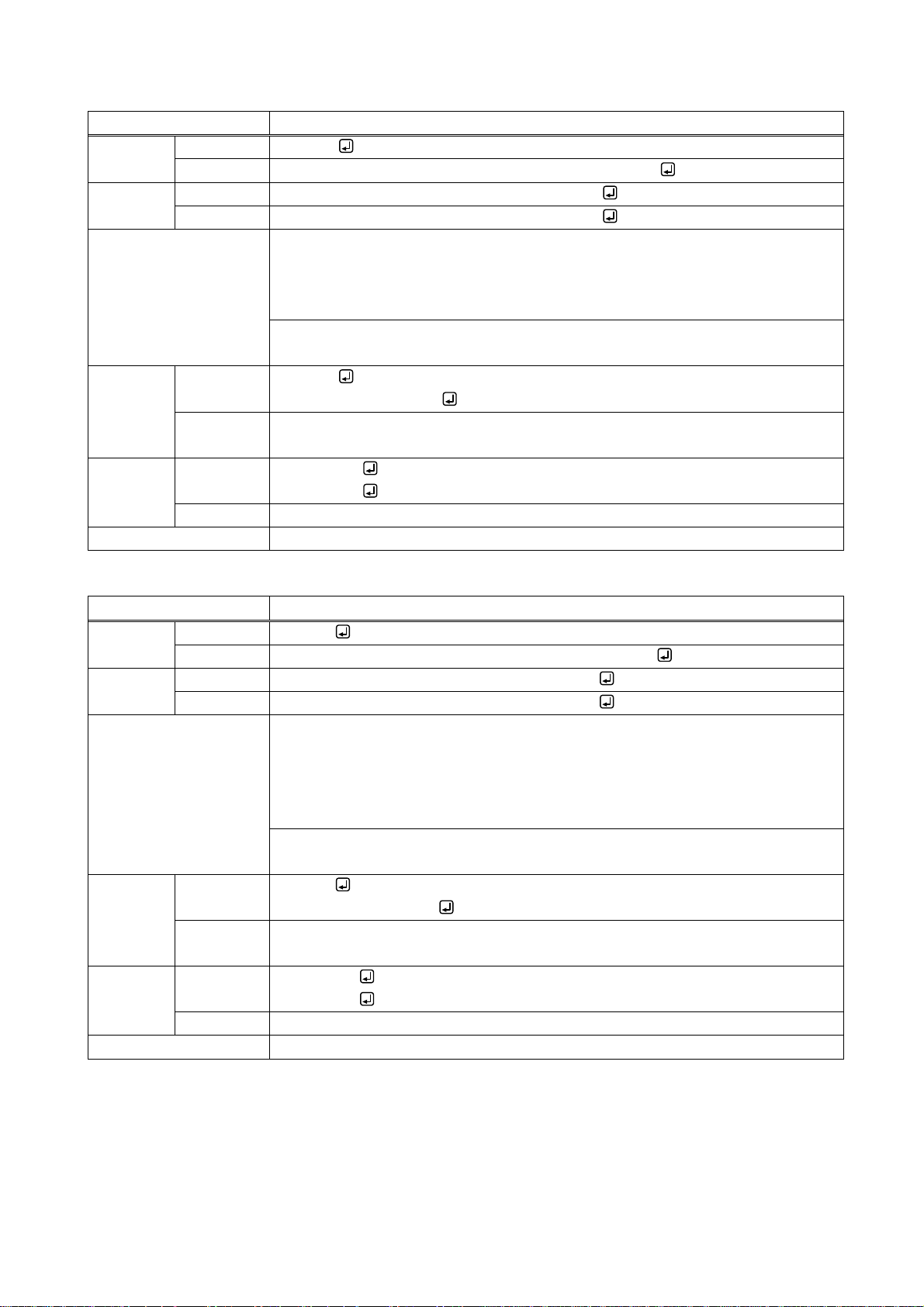
@GUM / @SUM
Aspect ratio of sink device
Response
@GUM, aspect_1, aspect_2, aspect_3,
, aspect_8
Response
@SUM, ch_1, aspect_1 (, ch_2, aspect_2
)
Parameter
aspect_1-6: Aspect ratio of sink device
0 = All outputs, 1 = OUT1 to 8 = OUT8
Description
Getting the set aspect rat io of the sink device.
example
Response
@SUM,1,4
Description
Setting OUT1 to 16:9.
Remarks
@GAP / @SAP
Aspect ratio
Response
@GAP, aspect_1, aspect_2, aspect _3,
, aspect_8
Setting
Command
@SAP, ch_1, aspect_1 (, c h_2, aspect_2
)
Response
@SAP, ch_1, aspect_1 (, c h_2, aspect_2
)
Parameter
aspect_1-10: Aspect ratio of input signal
8 = 14:9 SIDE PANEL, 9 = FULL, 10 = THROUGH
ch_1-8: Input channel
0 = All inputs, 1 = IN1 to 8 = IN8
Getting
Command
@GAP
IN3: 4:3, Other inputs: AUTO-1
Setting
Command
@SAP,7,2
Getting Command @GUM
・・・
Setting Command @SUM, ch_1, aspect_1 (, ch_2, aspect_2・・・)
・・・
0 = RESOLUTION [Default], 1 = 4:3, 2 = 5:4,
3 = 5:3, 4 = 16:9, 5 = 16:10,
6 = 256:135
ch_1-8: Output channel
MSD-62 series Command Guide
Getting
example
Command
Response
@GUM
@GUM,4,4,4,4,5,5,5,5
OUT1 to OUT4: 16:9, OUT5 to OUT8: 16:10
Setting
Command
@SUM,1,4
-
Getting Command @GAP
0 = AUTO-1 [Default], 1 = AUTO-2,
2 = 4:3, 3 = 16:9, 4 = 14:9,
5 = 16:9 LETTER BOX, 6 = 14:9 LETTER BOX, 7 = 4:3 SIDE PANEL,
・・・
・・・
・・・
example
Response
@GAP,0,0,2,0,0,0,0,0
Description Getting the set aspect ratio.
example
Response
@SAP,7,2
Description Setti ng IN7 to 4:3.
Remarks -
23
Page 24
MSD-62 series Command Guide
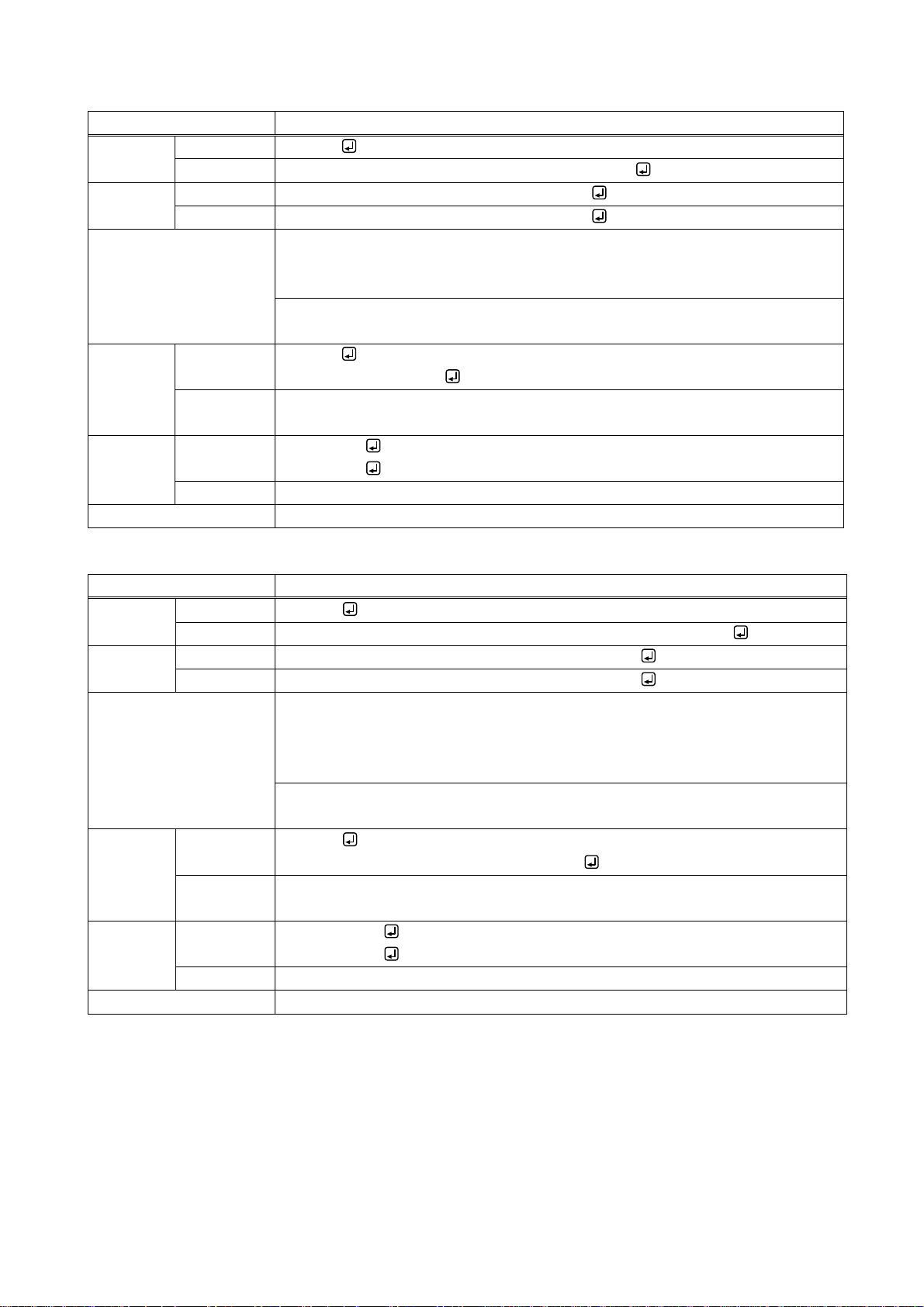
@G AR / @ SAR
Aspect ratio restorat io n
Response
@GAR, mode_1, mode_2, mode_3,
, mode_8
Response
@SAR, ch_1, mode_1 (, ch_2, mode_2
)
Parameter
mode_1-8: Aspect ratio restoration
1 = Side cut/Top bottom cut
ch_1-8: Input channel
example
Response
@GAR,0,0,1,0,0,0,0,0
IN3: Side cut/T op bott om cut , Other inputs: Letter box/Side panel
Setting
Command
@SAR,5,1
@GOV / @SOV
Overscan
Command
@GOV
Response
@SOV, ch_1, overscan_1 (, c h_2, overscan_2
)
HDTV / PC: 100
ch_1-8: Input channel
IN3: 105 %, Other inputs: 100 %
Setting
Command
@SOV,7,105
Getting Command @GAR
・・・
Setting Command @SAR, ch_1, mode_1 (, ch_2, mode_2・・・)
・・・
0 = Letter box/Si de panel [Default],
0 = All inputs, 1 = IN1 to 8 = IN8
Getting
Command
@GAR
Description Getting the set aspect ratio restorati on pr oc essing.
example
Response
@SAR,5,1
Description Setting IN5 to Side c ut/ Top bottom cut.
Remarks -
Getting
Response @GOV, overscan_1, overscan_2, overscan_3, ・・・, overscan_8
Setting Command @SOV , ch_1, overscan_1 (, ch_2, overscan_2・・・)
・・・
Parameter overscan_1-8: Over scan
100 to 115
[Default] NTSC / PAL / SDTV: 105,
0 = All inputs, 1 = IN1 to 8 = IN8
Getting
example
Command
Response
@GOV
@GOV,100,100,105,100,100,100,100,100
Description Get ting the set overscan.
example
Response
@SOV,7,105
Description Setting IN7 to 105%.
Remarks -
24
Page 25
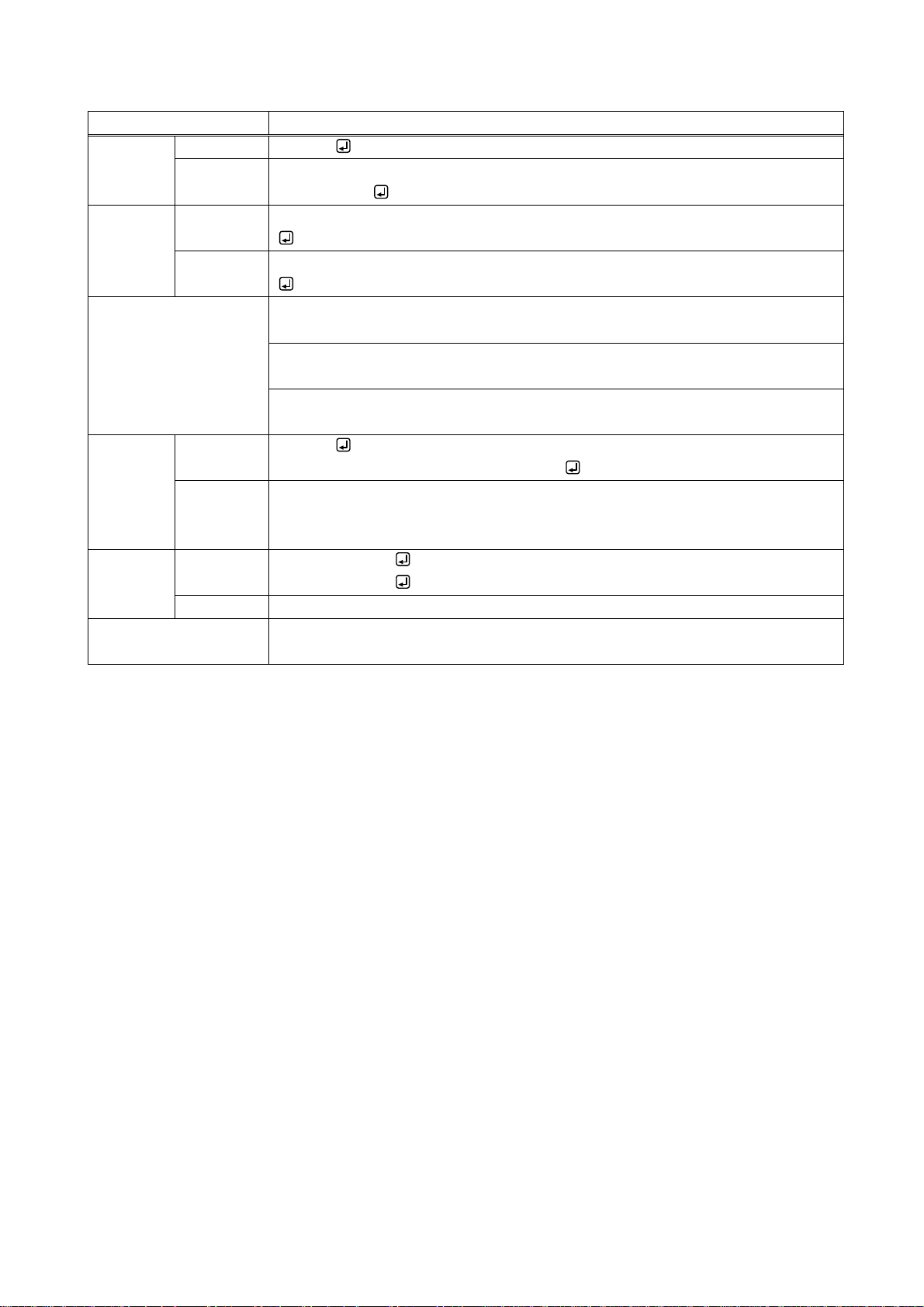
MSD-62 series Command Guide
@GNP / @SNP
Input position
Response
@GNP, h_position_1, v_position_1, h_position_2, v_position_2
, h_position_8,
Response
@SNP, ch_1, h_positi on_1, v_position_1 (, ch_2, h_posi tion_2, v_position_2
)
-Horizontal input si z e to +Horiz ontal output resoluti on [Default] 0
0 = All inputs, 1 = IN1 to 8 = IN8
example
Response
@GNP,-50,20,0,0,0,0,0,0,0,0,0,0,0,0,0,0
Description
Getting the set input position.
Other inputs: horiz ontal and vertical input posi tions are 0.
Setting
Command
@SNP,1,-50,20
standard.
Getting Command @GNP
・・・
v_position_8
Setting Command @S NP , ch_1, h_position_1, v_position_1 (, ch_2, h_position_2, v_position_2・・・)
・・・
Parameter h_position_1-8: Horizontal input position
v_position_1-8: Vertical input position
-Vertical input siz e to +Vertical output resolution [Default] 0
ch_1-8: Input channel
Getting
example
Description Setting IN1 horizontal and vertical input positions are to -50 and +20, respectively.
Remarks If resolutions differ depending on output, the OUT1 output resol ution will be the
Command
Response
@GNP
N1: horizontal input display is -50, vertical input displ ay i s +20.
@SNP,1,-50,20
25
Page 26
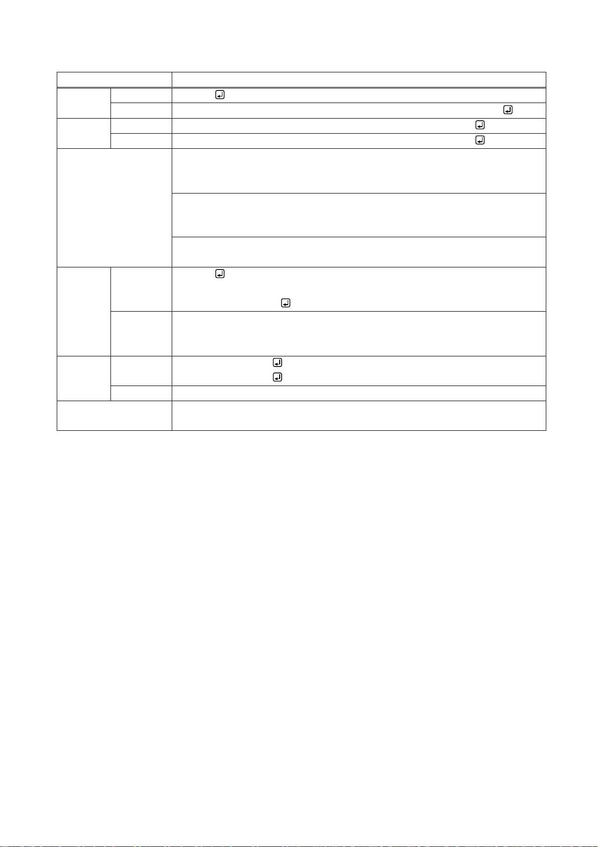
MSD-62 series Command Guide
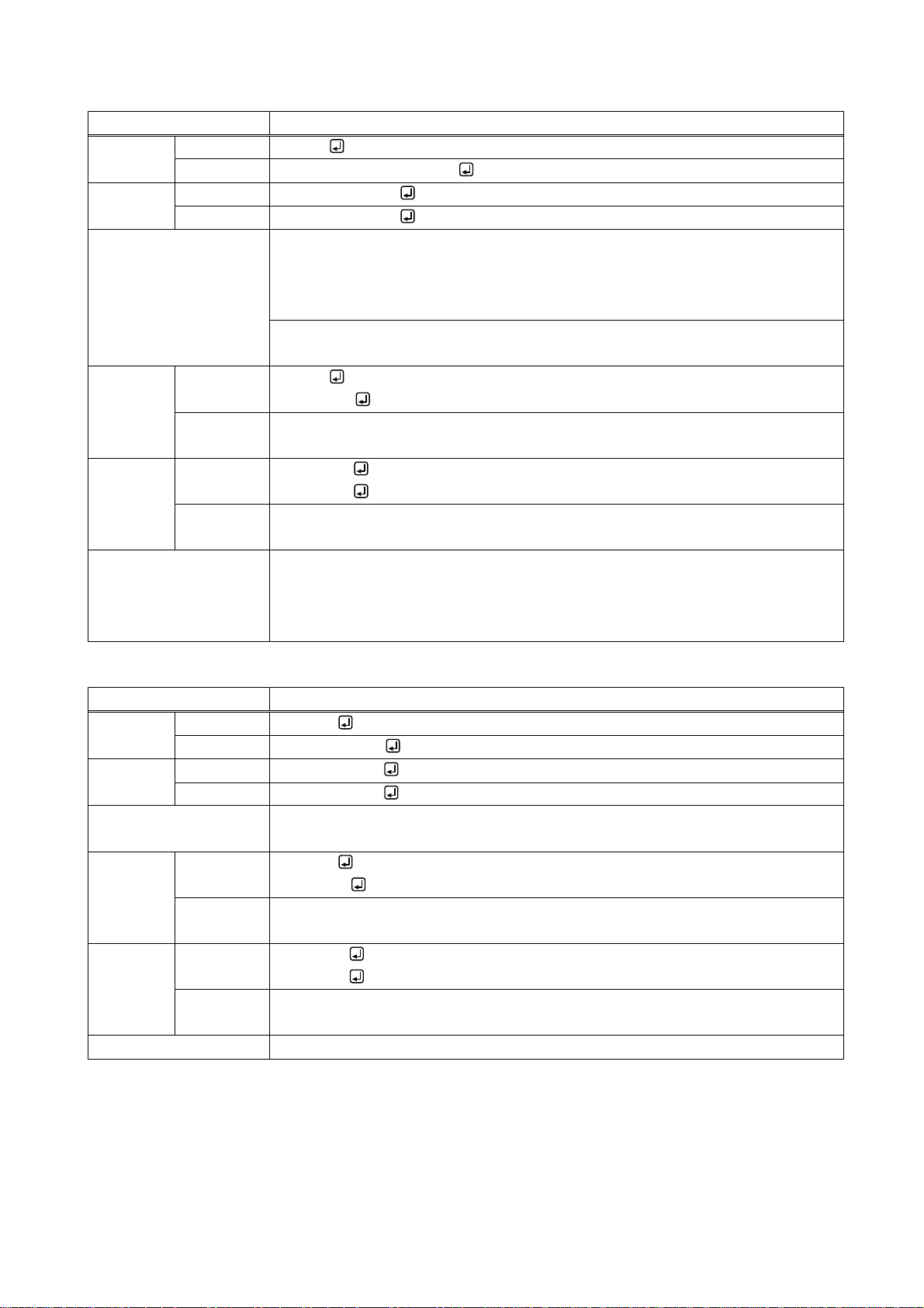
@GNS / @SNS
Input size
Response
@GNS, h_size_1, v _si z e_1, h_siz e_2, v_size_2
, h_size_8, v_size_8
Response
@SNS, ch_1, h_size_1, v_si z e_1 ( , ch_2, h_size_2, v_size_2
)
Parameter
h_size_1-8: Horizontal input size
[Default] Hori z ontal output resolution
v_size_1-8: Vertical input size
[Default] V ertic al output resolution
Getting
Command
@GNS
1920,1080,1920,1080
Description
Getting the set input siz e.
Other inputs: 1920 and 1080, r espect ively.
Setting
Command
@SNS,1,1925,1084
standard.
Getting Command @GNS
・・・
Setting Command @SNS, ch_1, h_size_1, v_size_1 (, ch_2, h_si z e_2, v_size_2・・・)
・・・
Horizontal out put resolution ÷4 to Horizont al output resolution ×4
Vertical output r esol ution ÷4 to Vertical output resol ution ×4
ch_1-8: Input channel
0 = All inputs, 1 = IN1 to 8 = IN8
example
example
Description Setting IN1 horizontal and vertical input size are 1925 and 1084, respect ively.
Remarks If resolutions differ depending on outputs, the resol ution of OUT1 will be the
Response
Response
@GNS,1925,1084,1920,1080,1920,1080,1920,1080,1920,1080,1920,1080,
Horizontal and ver tical display sizes of IN1 are 1925 and 1084, r espect ively.
@SNS,1,1925,1084
26
Page 27
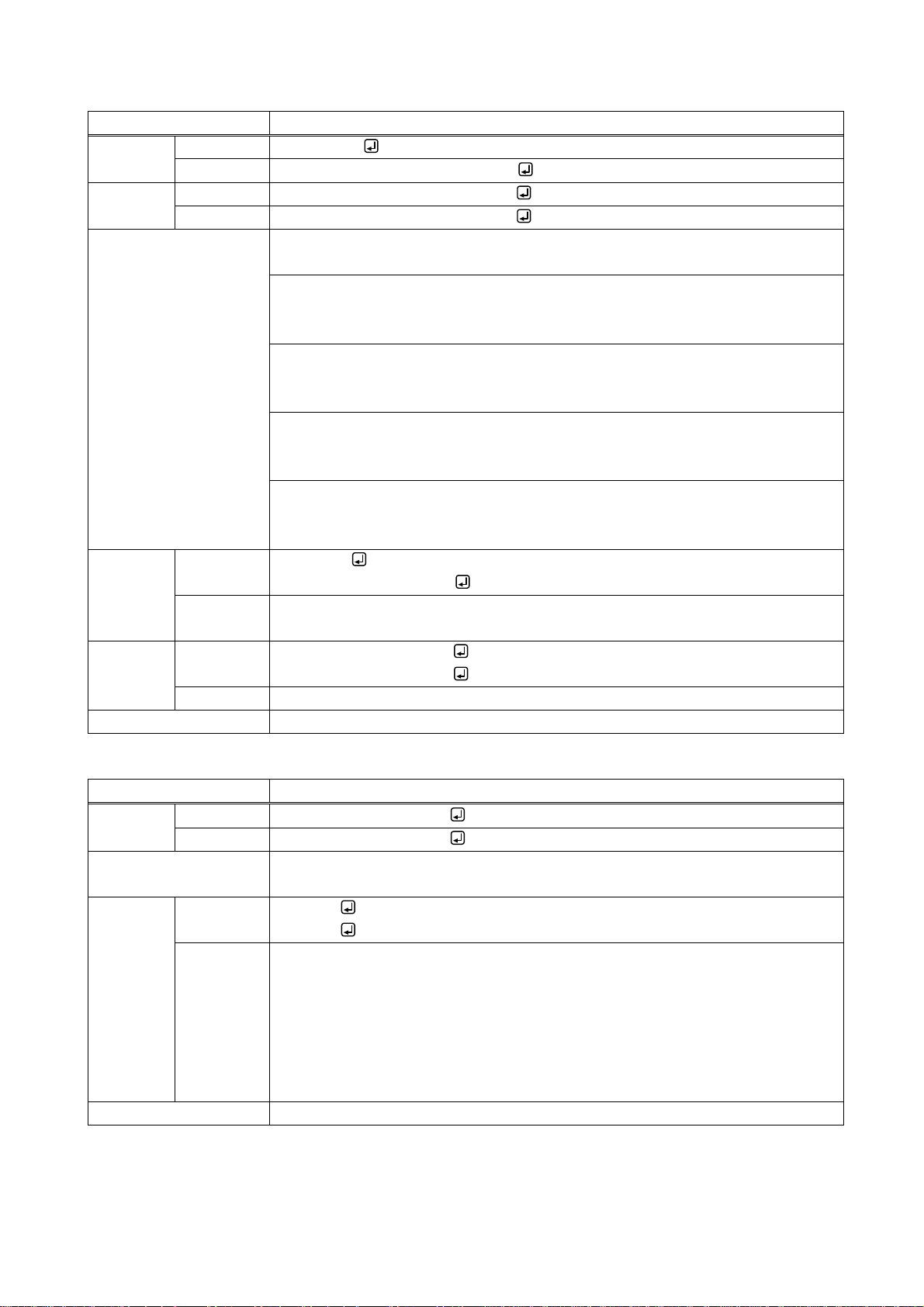
@GNM / @SNM
Input masking
Response
@GNM, ch , left, right, to p , bo ttom
Response
@SNM, ch, left, right , t op, bot tom
Parameter
ch: Input channel
top: Top side masking
[Default] 0
bottom: Bottom side masking
[Default] V ertic al input size
Getting
Command
@GNM,1
Left: 0, right: 1920, top: 0, bottom: 1080
example
Response
@SNM,1,0,1920,0,1080
Description
Setting IN1 input masking to 0 for left, 1920 for right, 0 for top, 1080 for bottom.
Remarks
@IAS
Input automatic sizing
example
Response
@IAS,1
Description
Initializing the following settings in order to display images input from IN1 on the
@GNM / @SNM Input masking
Getting Command @GNM, ch
Setting Command @SNM, ch, left, right, top, bott om
1 = IN1 to 8 = IN8
left: Left side masking
Horizontal input position to right side masking
[Default] 0
right: Right side masking
Left side maski ng to horiz ontal input position + horizontal input size
[Default] Hori z ontal input size
Vertical input position to bottom side masking
MSD-62 series Command Guide
Top side masking to vertical input position +vertical in put size
example
Response
@GNM,1,0,1920,0,1080
Description Getting the set IN1 input masking.
Setting
Command
@SNM,1,0,1920,0,1080
-
Setting Command @IAS, ch_1 (, ch_2・・・)
Response @IAS, ch_1 (, ch_2・・・)
Parameter ch_1-8: Input channel
0 = All inputs, 1 = IN1 to 8 = IN8
Setting
Command
@IAS,1
full screen:
@GAP / @SAP Aspect ratio
@GOV / @ SOV Overscan
@GNP / @SNP Input
@GNS / @SNS Input
position
size
Remarks -
27
Page 28
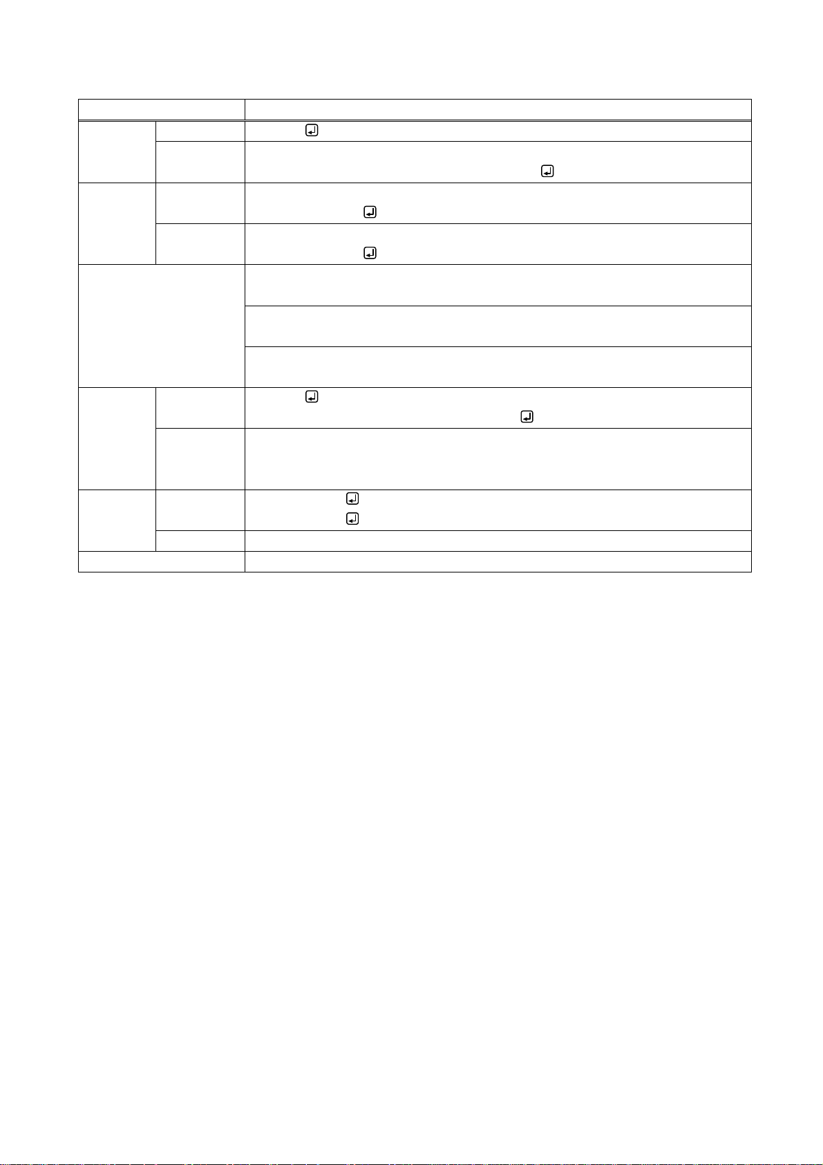
MSD-62 series Command Guide
@GOP / @SOP
Output position
Response
@GOP, h_position_1, v_position_1, h_position_2, v_position_2, h_position_3,
v_position_2
)
Response
@SOP, ch_1, h_position_1, v_position_1 (, c h_2, h_position_2,
-Horizontal output siz e to +Hori z ontal output resolution [Default] 0
0 = All outputs, 1 = OUT1 to 8 = OUT8
example
Response
@GOP,5,20,5,20,5,20,5,20,0,0,0,0,0,0,0,0
Description
Getting the set output posi tion.
OUT5 to OUT8: horizontal and vertical positions: 0
Setting
Command
@SOP,1,5,20
Remarks
Getting Command @GOP
v_position_3, ・・・, h_position_8, v_position_8
Setting Command @SOP, ch_1, h_position_1, v_positi on_1 (, c h_2, h_position_2,
・・・
v_position_2・・・)
Parameter h_position_1-8: Horizontal out put position
v_position_1-8: Ver tical output position
-Vertical output size to +Vertical output resolution [Default] 0
ch_1-8: Output channel
Getting
example
Description Setting OUT1 horizontal and vertical positions to +5 and +20, respectively.
Command
Response
@GOP
OUT1 to OUT4: horizontal position is +5, vertical position is +20.
@SOP,1,5,20
-
28
Page 29
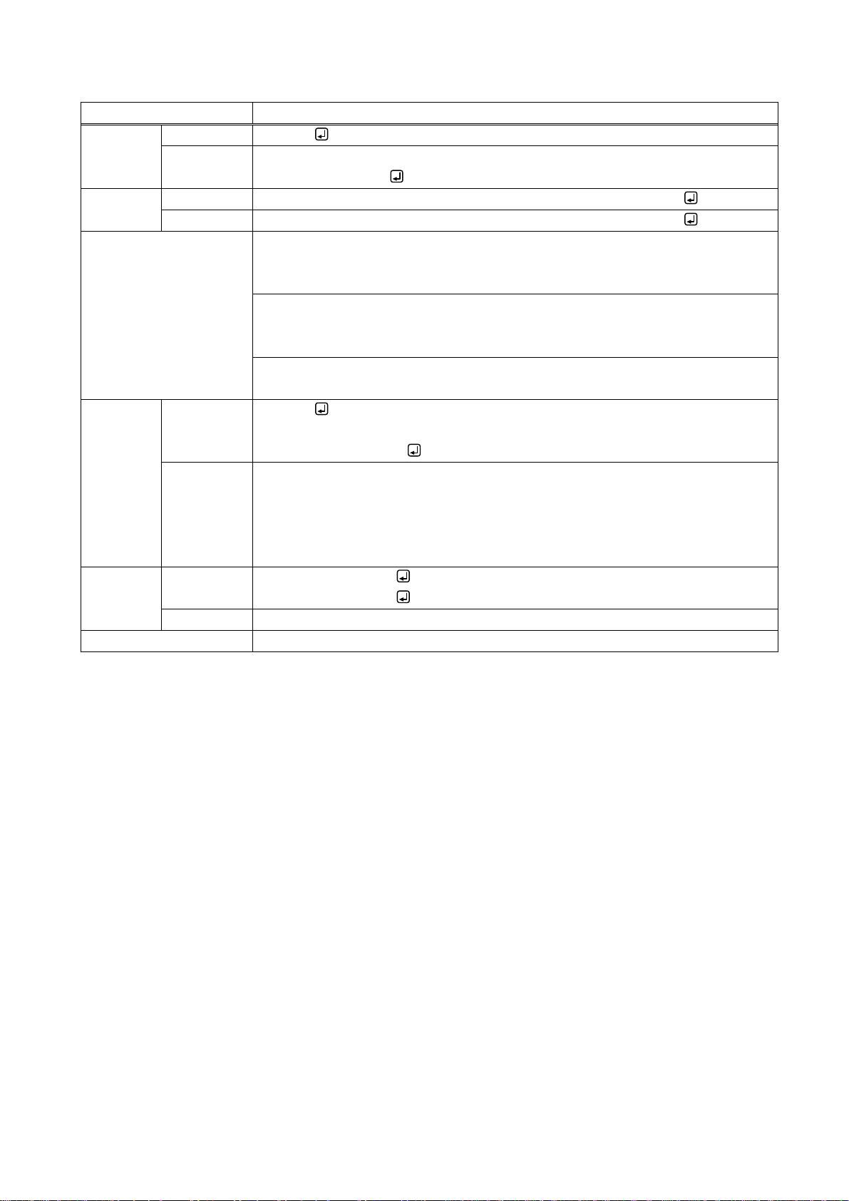
@GOS / @SOS
Output size
Response
@GOS, h_size_1, v_size_1, h_size_2, v_size_2, h_size_3, v_size_3,
,
Command
@SOS, ch_1, h_size_1, v _si z e_1 (, c h_2, h_siz e_2, v_size_2
)
0 = All outputs, 1 = OUT1 to 8 = OUT8
Setting
Command
@SOS,1,1920,1080
Getting Command @GOS
h_size_8, v_size_8
Setting
Response @SOS, ch_1, h_si z e_1, v_size_1 (, ch_2, h_size_2, v _size_2・・・)
Parameter h_size_1-8: Horizont al output size
Horizontal output resolution÷4 to Horizontal output resolution×4
[Default] Horizontal output resolut ion
v_size_1-8: Vertical output size
Vertical output r esol ution÷4 to Vertical output resolution×4
[Default] Vertical output resolution
ch_1-8: Output channel
MSD-62 series Command Guide
・・・
・・・
Getting
example
Description Get ting the set output size.
example
Description Setting OUT1 horizontal and vertical output sizes to 1920 and 1080, respect ively.
Remarks -
Command
Response
Response
@GOS
@GOS,1920,1035,1920,1035,1920,1035,1920,1035,1920,1080,1920,1080,
1920,1080,1920,1080
OUT1 to OUT4: horizontal output size is 1920, vertical output size is 1035,
respectively.
OUT5 to OUT8: horizontal output size is 1920, vertical output size is 1080,
respectively.
@SOS,1,1920,1080
29
Page 30
MSD-62 series Command Guide
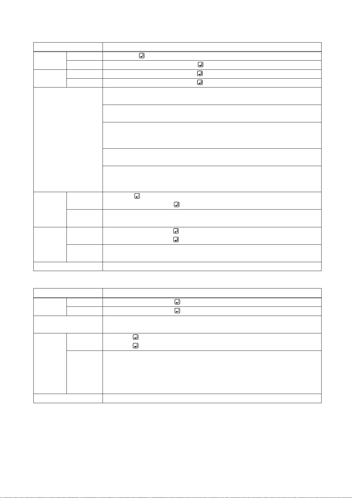
@GOM / @SOM
Output masking
Response
@GOM, ch, left, right, top, bottom
Response
@SOM, ch, left, right, t op, bot tom
Parameter
ch: Output channel
Horizontal out put position (0 or larger) to right side masking [Default] 0
right: Right side m asking
(horizontal output resolution or smaller) [Default] Horizontal output resolution
Vertical output posi tion (0 or larger) to bottom si de masking [Default] 0
bottom: Bottom side masking
(vertical output resolution or smaller ) [Default] Vertical output resol ution
Getting
Command
@GOM,1
Left: 0, right: 1920, top: 0, bottom: 1080
Setting
example
Command
Response
@SOM,1,0,1920,0,1080
@SOM,1,0,1920,0,1080
Description
Setting OUT1 output masking to 0 for left, 1920 for right, 0 for top, and 1080 for
@OAS
Output automatic sizing
Setting
Command
@OAS, ch_1 (, ch_2
)
Response
@OAS, ch_1 (, ch_2
)
Parameter
ch_1-8: Output channel
0 = All outputs, 1 = OUT1 to 8 = OUT8
Setting
Command
@OAS,1
masking
Getting Command @GOM, ch
Setting Command @SOM, ch, l eft , right, top, bottom
1 = OUT1 to 8 = OUT8
left: Left side maski ng
Left side masking to Horizontal output posi tion+horizontal output siz e
top: T op side maski ng
Top side masking to verti c al output position+vertical output si z e
example
Response
@GOM,1,0,1920,0,1080
Description Getting the set OUT1 output masking.
bottom.
Remarks -
・・・
・・・
example
Response
@OAS,1
Description Initializing the following settings in order to display OUT1 output images on the full
screen:
@GOP / @ SOP Output position
@GOS / @ SOS Output
@GOM / @SOM
Output
size
Remarks -
30
Page 31
MSD-62 series Command Guide
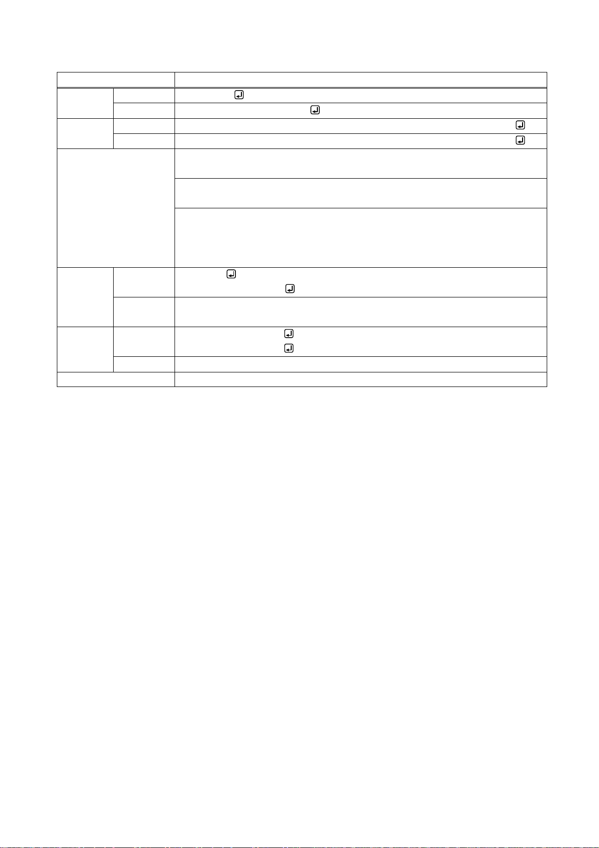
@GBC / @SBC
Background color
Response
@GBC, ch, red, green, blue
Response
@SBC, ch_1, red_1, green_1, blue_1 (, ch_2, red_2, green_2, bl ue_2
)
Parameter
ch: Output channel
0 = All outputs, 1 = OUT1 to 8 = OUT8
red / red_1-8 : Background c olor ( Red)
Getting
Command
@GBC,1
RGB: 128 (Gray)
Setting
Command
@SBC,1,128,128,128
Getting Command @GBC, ch
Setting Command @SBC, ch_1, red_1, green_1, blue_1 (, ch_2, red_2, green_2, bl ue_2・・・)
・・・
1 = OUT1 to 8 = OUT8
ch_1-8: Out put channel
green / green_1-8 : Bac k ground color (Green)
blue / blue_1-8 : Background color (Blue)
0 to 255 [Default] 0 (Black)
example
Description Getting the set OUT1 background color.
example
Description Setti ng OUT1 background color to 128 (Gray ) for all RGB.
Remarks -
Response
Response
@GBC,1,128,128,128
@SBC,1,128,128,128
31
Page 32
MSD-62 series Command Guide
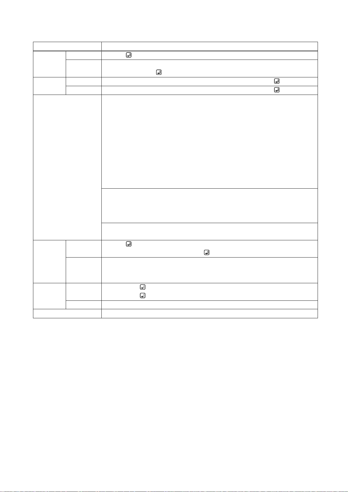
@GTP / @S TP
Test pattern
Response
@GTP, pattern_1, scroll_1, pattern_2, scroll_2, pattern_3, scroll_3,
,
Command
@STP, ch_1, pattern_1, scroll_1 (, ch_2, pattern_2, scroll_2
)
Test pattern number s 1 to 6, 16 and 17 can be scrolled.
scroll_1-8: Scrolling
0 = All outputs, 1 = OUT1 to 8 = OUT8
example
Response
@GTP,3,1,3,1,3,1,3,1,0,0,0,0,0,0,0,0
OUT5 to OUT8: test pattern is not output.
Setting
Command
@STP,1,1,0
Getting Command @GTP
pattern_8, scroll_8
Setting
Response @STP, ch_1, pattern_1, scroll_1 ( , ch_2, pattern_2, scroll _2・・・)
Parameter pattern_1-8: Test pattern
0 = OFF [Default], 1 = VERTICAL COLOR BAR,
2 = HORIZONTAL COLOR BAR, 3 = VERTICAL GRAY SCALE,
4 = HORIZONTAL GRAY SCALE, 5 = VERTICAL RAMP,
6 = HORIZONTAL RAMP, 7 = 100% WHITE RASTER,
8 = 50% WHITE RASTER, 9 = 100% RED RASTER,
10 = 100% GREEN RASTER, 11 = 100% BLUE RASTER,
12 = CROSS HATCH, 13 = OUTPUT FRAME,
14 = VERTICAL STRIPE, 15 = HORIZONTAL STRIPE,
16 = VERTICAL ZEBRA, 17 = HORIZONTAL ZEBRA
・・・
・・・
0 = OFF [Default],
1 = 3 pixels/1 frame to 10 = 30 pixels/1 f r am e
The number of pixels to be scrolled per frame = the set value×3
ch_1-8 : Output channel
Getting
Description Get ting the set test pattern.
example
Description Setting OUT1 to VERTICAL COLOR BAR without scrolli ng.
Remarks An error occurs if this menu is set while video combination mode is enabled.
Command
Response
@GTP
OUT1 to OUT4: VERTICAL GRAY SCALE at 3 pixels/frame scrolling
@STP,1,1,0
32
Page 33
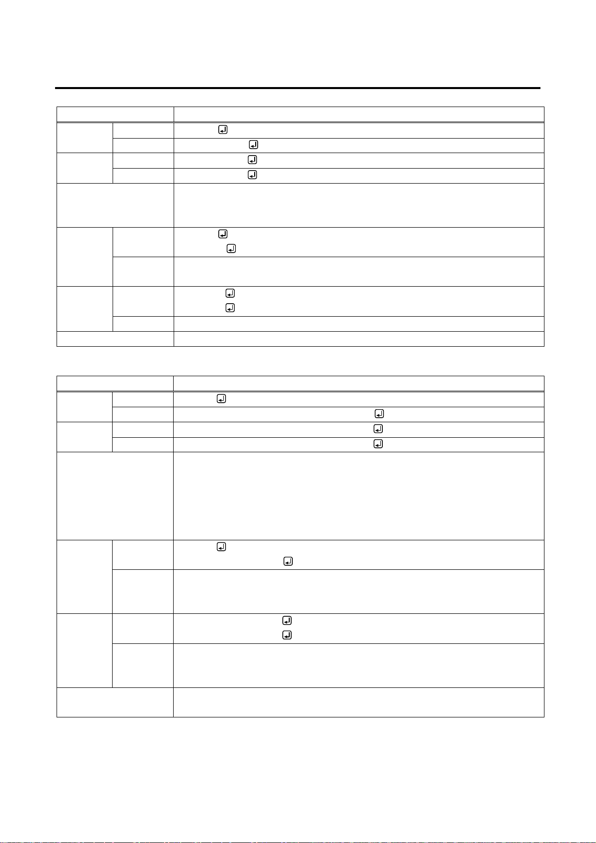
3.3.5 Video processing
@GOR / @SOR
Video proc e s s ing mode
Getting
Command
@GOR
Response
@GOR, mode
Command
@SOR, mode
Response
@SOR, mode
example
Response
@GOR,2
Description
Getting the video processing mode.
example
Response
@SOR,2
Remarks
@GPR / @SPR
Window display priority
Getting
Command
@GPR
Response
@GPR, priority_1, priority_2, …, priority_8
Setting
Command
@SPR, priority_1, priority_2, …, priority_8
Response
@SPR, priority_1, priority_2, …, priority_8
Parameter
priority_1-8: Window priority
WINDOW5>WINDOW6>WINDOW7>WINDOW8
Getting
Command
@GPR
For MSD-6206 and MSD-6208, priorities have to be set for all eight windows.
Setting
Parameter mode: Video processing mode
Getting
Setting
Description Setting this menu to 4K mode.
Command
Command
0 = Normal [Default], 1 = Video com bination
2 = 4K
@GOR
4K mode.
@SOR,2
-
MSD-62 series Command Guide
example
Description Getting the set window priorit y:
Setting
example
Description Setting this menu:
Remarks For MSD-6203 and MSD-6204, prior ities have to be set for all four windows.
Response
Command
Response
1 = priority 1 (high) to 4 = priority 4 (low)
[Default] 1,2,3,4 (WINDOW1 to WINDOW4)
WINDOW1>WINDOW2>WINDOW3>WINDOW4
1,2,3,4 (WINDOW 5 to WINDOW8)
@GPR,2,4,1,3,3,1,2,4
WINDOW1 to WINDOW4: WINDOW3>WINDOW1>WINDOW4>WINDOW2
WINDOW5 to WINDOW8: WINDOW6>WINDOW7>WINDOW5>WINDOW8
@SPR,4,3,2,1,1,2,3,4
@SPR,4,3,2,1,1,2,3,4
WINDOW1 to WINDOW 4: WINDOW4>WINDOW3>WINDOW2>WINDOW1
WINDOW5 to WINDOW 8: WINDOW5>WINDOW6>WINDOW7>WINDOW8
33
Page 34
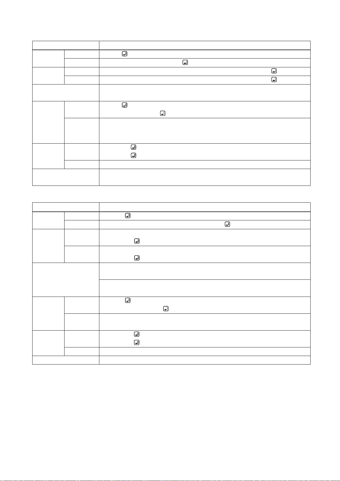
MSD-62 series Command Guide
@GOI / @SOI
Flip horiz o nt a l
Response
@GOI, flip_1, flip_2, …, flip_8
Response
@SOI, window_1, flip_1, (window_2, fli p_2, …, window_8, flip_8)
Parameter
flip_1-8: Flip horiz ontal
example
Response
@GOI,0,1,0,0,0,0,0,0
Description
Getting the Flip horizontal setting.
Other windows: Horizontal flip OFF
example
Response
@SOI,3,1
Description
Setting the WINDOW3 to horizontal flip ON.
@GWV / @SWV
Hiding window
Command
@GWV
Response
@GWV, invisible_1, invisible_2, …, invisible_8
invisible_8)
Response
@SWV, window_1, invisible_1, (window_2, i nv isible_2, …, window_8,
0 = Display [Default], 1 = Hide
window_1-8: Window
example
Response
@GWV,0,0,0,0,0,1,0,0
WINDOW6: Hide; Other windows: Display
Getting Command @GOI
Setting Command @SOI, window_1, flip_1, (window_2, fli p_2, …, window_8, fl ip_8)
0 = OFF [Default], 1 = ON
Getting
Command
@GOI
WINDOW2: Horizontal flip ON
Setting
Command
@SOI,3,1
Remarks An error occurs if thi s menu is set while 4K m ode is enabl ed.
【See: @GOR / @SOR Video processing mode】
Getting
Setting Command @SWV, window_1, invisible_1, (window_2, i nv isible_2, …, window_8,
invisible_8)
Parameter invisible_1-8: Hiding window setti ng
0 = All WINDOW, 1 = WINDOW1 to 8 = WINDOW8
Getting
Command
@GWV
Description Getting the hiding window setting.
Setting
example
Command
Response
@SWV,6,0
@SWV,6,0
Description Setti ng the WINDOW6 t o displ ay .
Remarks -
34
Page 35
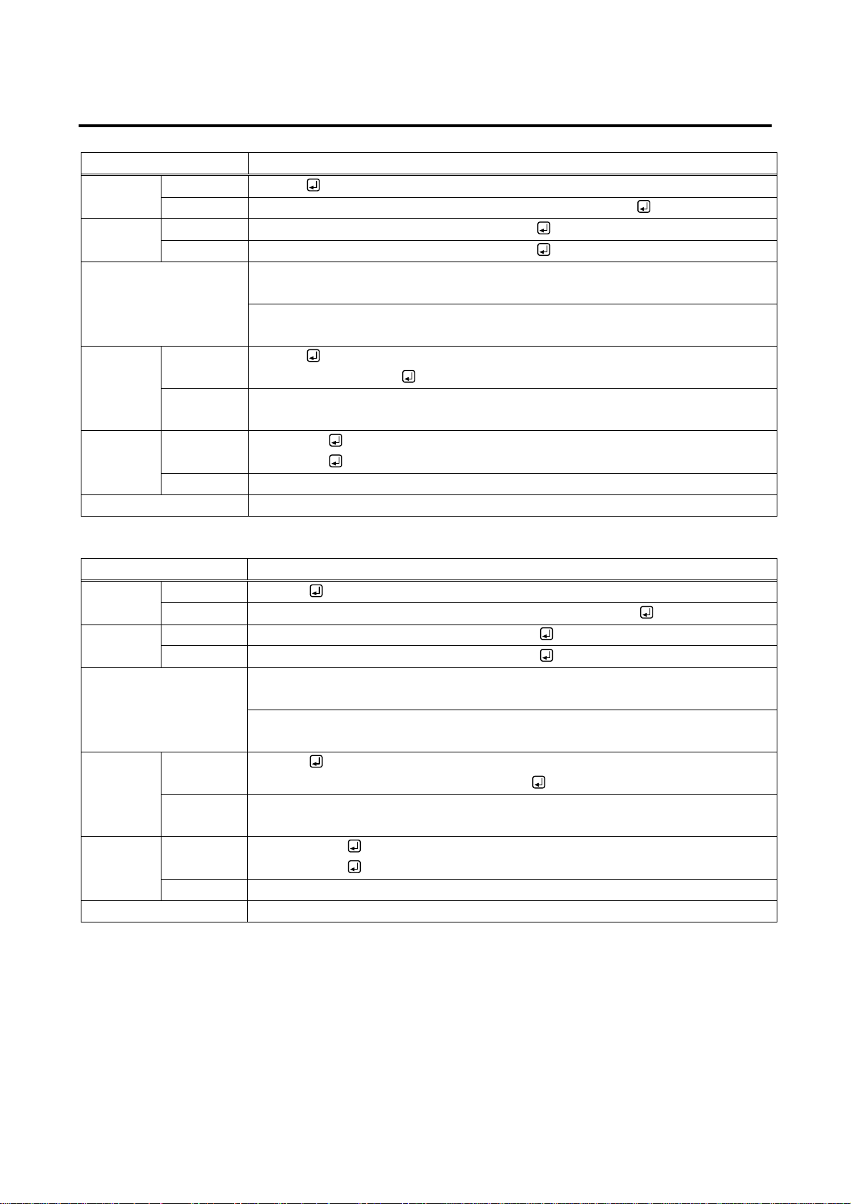
3.3.6 Image quality
@GFL / @SFL
Sharpness
Getting
Command
@GFL
Response
@GFL, sharp_1, sharp_2, sharp_3, shar p_4,
, sharp_8
Command
@SFL, ch_1, sharp_1 (, ch_2, sharp_2
)
Response
@SFL, ch_1, sharp_1 (, ch_2, sharp_2
)
-5 to +15 [Default] 0
example
Response
@GFL,5,0,0,0,0,0,0,0
Description
Getting sharpness setting.
Description
Setting the IN1 sharpness to +5.
@GBR / @SBR
Input brightness
Getting
Command
@GBR
Response
@GBR, bright_1, bright_2, bright_3, bright_4,
, bright_8
Command
@SBR, ch_1, bright _1 (, c h_2, bright_2
)
Response
@SBR, ch_1, bright _1 (, c h_2, bright_2
)
80 to 120 [Default] 100
example
Response
@GBR,110,100,100,100,100,100,100,100
Description
Getting bright ness sett ing.
example
Response
@SBR,3,110
Description
Setting the IN3 bright ness to 110%.
Remarks
Setting
Parameter sharp_1-8: Input sharpness
ch_1-8: Input c hannel
0 = All inputs, 1 = IN1 to 8 = IN8
Getting
Setting
example
Command
Command
Response
@GFL
IN1: +5, other input channels: 0
@SFL,1,5
@SFL,1,5
MSD-62 series Command Guide
・・・
・・・
・・・
Remarks -
Setting
Parameter bright_1-8 : Input brightness
ch_1-8: Input channel
0 = All inputs, 1 = IN1 to 8 = IN8
Getting
Setting
Command
Command
@GBR
IN1: 110 %, other input channels: 100 %
@SBR,3,110
-
・・・
・・・
・・・
35
Page 36
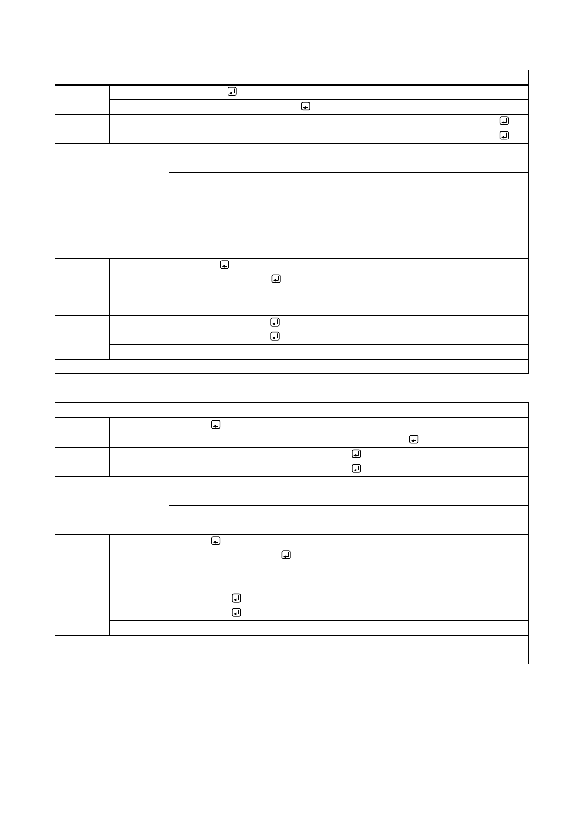
MSD-62 series Command Guide
@GCO / @ SCO
Input contrast
Response
@GCO, ch, red, green, blue
Response
@SCO, ch_1, red_1, green_1, blue_1 (, ch_2, red_2, green_2, bl ue_2
)
Parameter
ch: Input channel
0 = All inputs, 1 = IN1 to 8 = IN8
red / red_1-8 : Input contrast ( Red)
Getting
Command
@GCO,3
Red: 105 %, Green: 100 %, Blue: 95 %
Setting
Command
@SCO,3,105,100,95
@GHU / @SHU
Hue
0 to 359 [Default] 0
example
Response
@GHU,60,0,0,0,0,0,0,0
IN1: 60°, other inputs: 0°
Setting
Command
@SHU,1,60
170 MHz, 0 ° is applied regardless of this setti ng.
Getting Command @GCO, ch
Setting Command @SCO, ch_1, red_1, green_1, blue_1 (, ch_2, red_2, green_2, blue_2・・・)
・・・
1 = IN1 to 8 = IN8
ch_1-8: Input c hannel
green / green_1-8 : Input contrast (Green)
blue / blue_1-8 : Input contrast (Blue)
0 to 200 [Default] 100
example
Response
@GCO,3,105,100,95
Description Getting IN3 contrast setting.
example
Response
@SCO,3,105,100,95
Description Setti ng IN3 contrast to 105% for red, 100% for green, 95% f or blue.
Remarks -
Getting Command @GHU
Response @GHU, hue _1, hue _2, hue _3, hue _4, ・・・, hue _8
Setting Command @SHU, ch_1, hue_1 (, ch_2, hue_2・・・)
Response @SHU, ch_1, hue_1 (, ch_2, hue_2・・・)
Parameter hue_1-8: I nput hue
ch_1-8: Input c hannel
0 = All inputs, 1 = IN1 to 8 = IN8
Getting
Command
@GHU
Description Getting the set HUEs.
example
Response
@SHU,1,60
Description S etting IN1 HUE to 60°.
Remarks Hue can be set up to 359 °. However, if the dot cl oc k of the input si gnal ex c eeds
36
Page 37
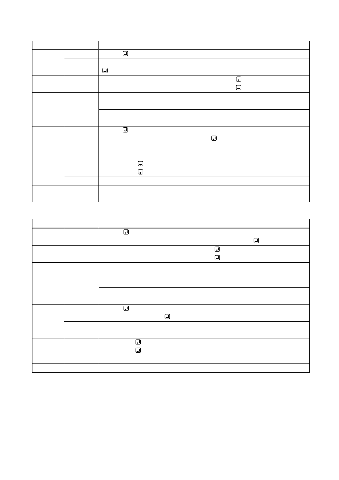
@GST / @SST
Saturation
Response
@GST, saturation_1, saturation_2, saturation_3, saturation_4,
, saturation_8
Command
@SST, ch_1, saturation_1 (, ch_2, saturati on_2
)
0 to 200 [Default] 100
ch_1-8: Input channel
example
Response
@GST,100,100,100,100,105,100,100,100
IN5: 105 %, other inputs: 100 %
Setting
Command
@SST,5,105
170 MHz, 100% is applied regardless of this setting.
@GSU / @SSU
Black level
Response
@GSU, setup_1, setup_2, setup_3, setup_4,
, setup_8
Setting
Command
@SSU, ch_1, setup_1 (, ch_2, setup_2
)
Response
@SSU, ch_1, setup_1 (, ch_2, setup_2
)
Parameter
setup_1-8: Input blac k lev el
[Default] ±0 = ±0.0 %
ch_1-8: Input channel
IN5: +7.5%, other inputs: 0%.
Setting
Command
@SSU,5,15
Getting Command @GST
Setting
Response @SST, ch_1, saturation_1 (, ch_2, saturation_2・・・)
Parameter saturation_1-8: Input saturation
0 = All inputs, 1 = IN1 to 8 = IN8
Getting
Command
@GST
Description Get ting the set saturations.
MSD-62 series Command Guide
・・・
・・・
example
Response
@SST,5,105
Description Setting IN5 saturation to 105%.
Remarks Hue can be set up to 200%. However, if the dot cloc k of the input si gnal ex c eeds
Getting Command @GSU
・・・
・・・
・・・
-20 = -20 × 0.5 (-10.0 %) to +20 = +20 × 0.5 (+10.0 %)
0 = All inputs, 1 = IN1 to 8 = IN8
Getting
example
Command
Response
@GSU
@GSU,0,0,0,0,15,0,0,0
Description Getting the input black level.
example
Response
@SSU,5,15
Description Setting the IN5 black level to +7.5%.
Remarks -
37
Page 38
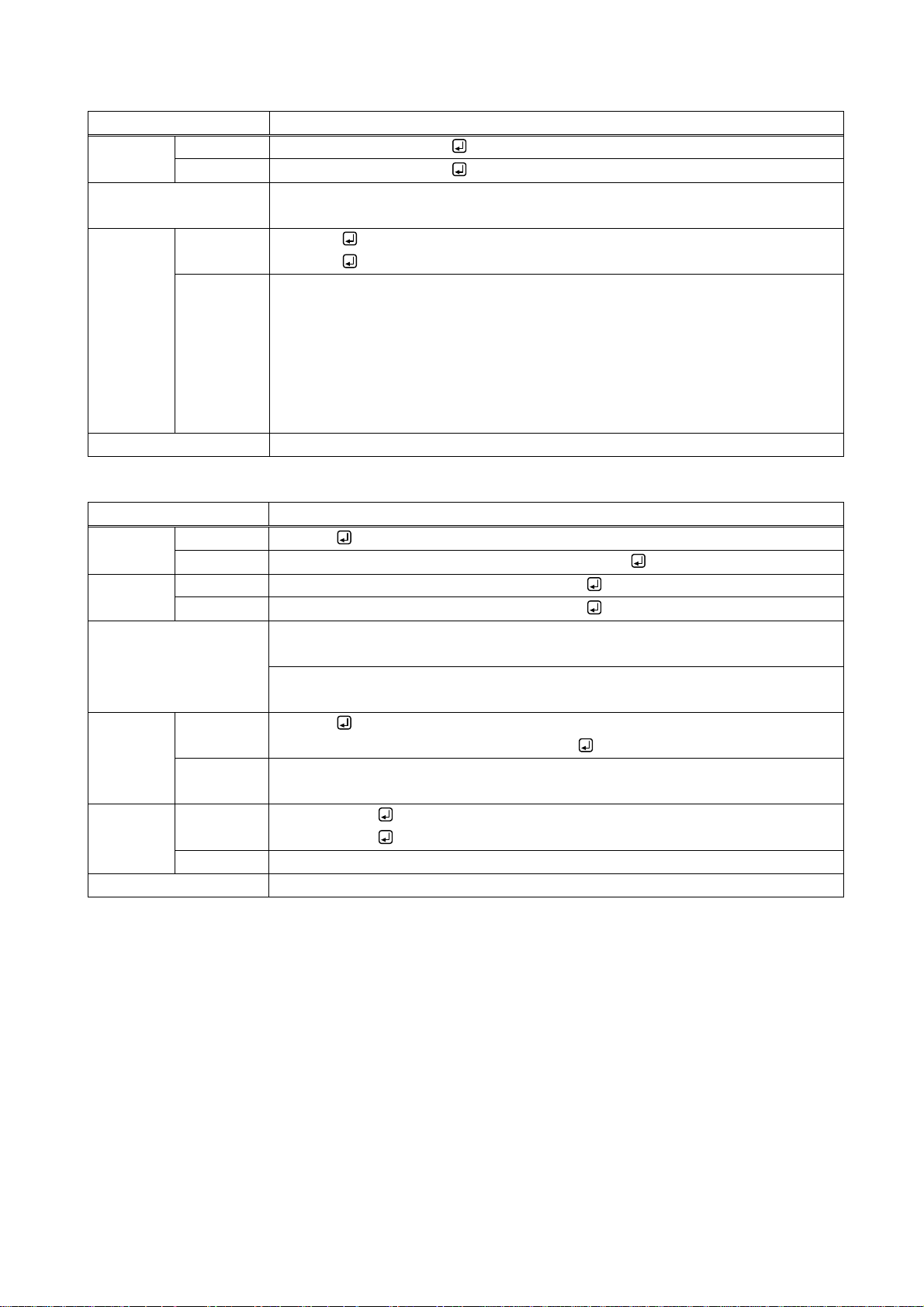
MSD-62 series Command Guide
@IDC
Input default color
Response
@IDC, ch_1 (, ch_2
)
0 = All inputs, 1 = IN1 to 8 = IN8
example
Response
@IDC,1
Description
Initialize the following setti ngs of IN1:
@GSU / @SSU Black level
@GOB / @SOB
Output brightness
Getting
Command
@GOB
Response
@GOB, bright_1, bright_2, bright_3,
, bright_8
Command
@SOB, ch_1, bright_1 (, c h_2, bright_2
)
Response
@SOB, ch_1, bright_1 (, c h_2, bright_2
)
80 to 120 [Default] 100
example
Response
@GOB,110,110,110,110,100,100,100,100
Description
Getting the output bri ghtness.
example
Response
@SOB,1,110
Description
Setting the OUT1 bri ghtness to 110%.
Setting Command @IDC, ch_1 (, ch_2・・・)
・・・
Parameter ch_1-8: Input channel
Setting
Command
@IDC,1
@GFL / @SFL Sharpness
@GBR / @SBR Input
@GCO / @SCO Input
@GHU / @SHU Hue
@GST / @SST Saturation
brightness
contrast
Remarks -
Setting
Parameter bright_1-8: Output brightness
ch_1-8: Output channel
0 = All outputs, 1 = OUT1 to 8 = OUT8
Getting
Command
@GOB
・・・
・・・
・・・
Setting
Command
Remarks -
OUT1 to OUT4: 110 %, OUT5 to OUT8: 100 %
@SOB,1,110
38
Page 39
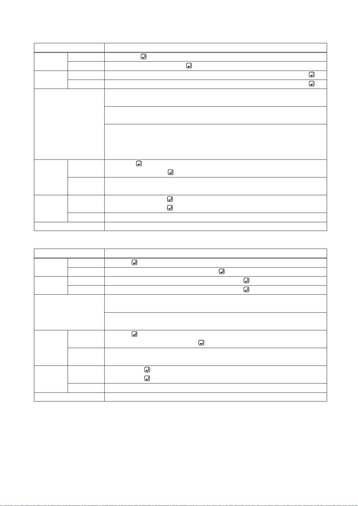
MSD-62 series Command Guide
@GOC / @ SOC
Output contrast
Response
@GOC, ch, red, green, blue
Response
@SOC, ch_1, red_1, green_1, blue_1 (, ch_2, red_2, green_2, blue_2
)
Parameter
ch: Output channel
0 = All outputs, 1 = OUT1 to 8 = OUT8
red / red_1-8 : Output contrast (Red)
Getting
Command
@GOC,1
Red: 105%, green: 100%, blue: 95%
Setting
Command
@SOC,1,105,100,95
@GGM / @SGM
Output gamma
1 = 0.1 to 30 = 3.0 [Default] 10 = 1.0
example
Response
@GGM,22,10,10,10,10,10,10,10
OUT1: 2.2, Others: 1.0
Setting
Command
@SGM,1,22
Getting Command @ GOC, ch
Setting Command @SOC, ch_1, red_1, green_1, blue_1 (, ch_2, red_2, green_2, blue_2・・・)
・・・
1 = OUT1 to 8 = OUT 8
ch_1-8: Out put channel
green / green_1-8 : Output contrast (Green)
blue / blue_1-8 : Output contrast (Blue)
0 to 200 [Default] 100
example
Description Getting the OUT1 contrast setting.
example
Description Setti ng the OUT1 contrast to 105% for red, 100% for green, 95% for blue.
Remarks -
Getting Command @GGM
Setting Command @SGM, ch_1, gamma_1 (, ch_2, gammma_2・・・)
Parameter out_1-8 / gamma_1-8: Output gamma
ch_1-8: Out put channel
Getting
Response
Response
Response @GGM, out_1, out_2, out _3, ・・・, out_8
Response @SGM, ch_1, gamma_1 (, ch_2, gammm a_2・・・)
Command
@GOC,1,105,100,95
@SOC,1,105,100,95
0 = All outputs, 1 = OUT1 to 8 = OUT8
@GGM
Description Getting the set output gamma.
example
Description S etting the OUT1 output gamm a to 2.2.
Remarks -
Response
@SGM,1,22
39
Page 40
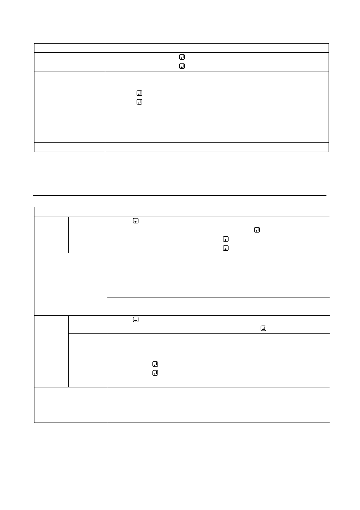
MSD-62 series Command Guide
@ODC
Output default color
Response
@ODC, ch_1 (, ch_2
)
0 = All outputs, 1 = OUT1 to 8 = OUT8
example
Response
@ODC,1
Description
Initializing OUT1 image quality settings.
@GGM / @SGM Output gamma
@GDT / @ SDT
No-signal-input monitoring
(For example, if you set it t o 2955, t he m onitoring time is set to 2900 ms.)
example
Response
@GDT,6000,10000,10000,4000,4000,4000,4000,4000
Description
Getting the set monitoring time of input video signal.
IN4 and IN8: 4000 ms. (4 sec.)
Setting
Command
@SDT,3,6000
Setting Command @ODC, ch_1 (, ch_2・・・)
・・・
Parameter ch_1-8: Output channel
Setting
Remarks -
Command
@ODC,1
@GOB / @SOB Output brightness
@GOC / @SOC Output
contrast
3.3.7 Input settings
Getting Command @GDT
Response @GDT, time_1, time_2, time_3, time_4, ・・・, time_8
Setting Command @S DT, c h_1, time_1 (, ch_2, time_2・・・)
Response @SDT, ch_1, time_1 (, ch_2, time_2・・・)
Parameter time_1-8: No-signal-input monitoring
0 = OFF, 2000 = 2 sec to 15000 = 15 sec [Default] 10000 = 10 sec
Set the value by 100 ms. If you set a value other than 0 for the lower 2 digits,
these values will be r ounded down.
ch_1-8: Input channel
0 = All d igita l input s, 1 = IN1 to 8 = IN8
Getting
example
Description Setting the monitoring time of IN3 to 6000 ms. (6 sec.).
Remarks These commands are only for digital input.
Command
Response
@GDT
IN1: 6000 ms. (6 sec.), IN2 and IN3: 10000 m s. (10 sec.),
@SDT,3,6000
IN7 and IN8 are available only if “1” (Digital signal) is select ed f or “@GIN / @SIN
Signal selection of DV I input conne c tor”. If “0” (Analog signal) is select ed, “-1”
is returned.
40
Page 41
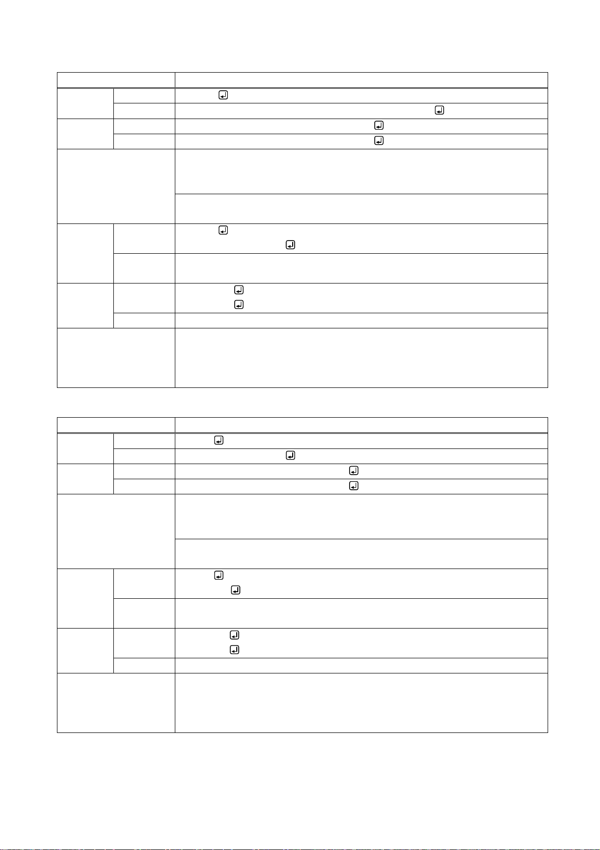
@GHE / @SHE
HDCP input enabled/disabled
Response
@GHE, hdcp_1, hdcp_2, hdcp_3, hdcp_4,
, hdcp_8
Response
@SHE, ch_1, hdcp_1 (, ch_2, hdcp_2
)
Parameter
hdcp_1-8 : HDCP input enabled/disabled
[Default] ENABLE
ch_1-8: Input channel
example
Response
@GHE,1,1,0,1,1,1,1,1
IN3: disables HDCP input , other input channels: enables HDCP input
Setting
Command
@SHE,1,0
is returned.
@GAI / @SAI
Analog in put type
Response
@GAI, type_1, type_2
Setting
Command
@SAI, ch_1, type_1 (, c h_2, t y pe_2)
Response
@SAI, ch_1, type_1 (, c h_2, t y pe_2)
Parameter
type_1-2: Signal type
3 = VIDEO AUTO, 4 = VIDEO, 5 = Y/C
ch_1-2: Input channel
0 = All analog inputs, 7 = IN7, 8 = IN8
Getting
Command
@GAI
IN7: AUTO, IN8: YPbPr
Setting
Command
@SAI,0,2
Getting Command @GHE
Setting Command @SHE, ch_1, hdcp_1 (, ch_2, hdcp_2・・・)
・・・
0 = DISABLE, 1 = ENABLE
0 = All d igita l input s, 1 = IN1 to 8 = IN8
Getting
Command
@GHE
Description Getting HDCP input enabled/di sabl ed.
MSD-62 series Command Guide
・・・
example
Response
@SHE,1,0
Description Setti ng IN1 HDCP input to be disabled.
Remarks These commands are only for digital input.
IN7 and IN8 are available only if “1” (Digital signal) is select ed f or “@GIN / @SIN
Signal selection of DVI input connector
Getting Command @GAI
0 = AUTO [Default], 1 = RGB, 2 = YPbPr,
example
Response
@GAI,0,2
Description Getting signal type of analog input .
”. If “0” (Analog signal ) is selected, “-1”
example
Response
@SAI,0,2
Description Setti ng the signal type of IN7 and IN8 to YPbPr.
Remarks These commands are only for analog input.
IN7 and IN8 are available only if “0” (Analog signal) is selected for “@GIN / @SIN
Signal selection of D VI input connec t or ”. I f “1” (Digital signal) is selected, “-1” is
returned.
41
Page 42
MSD-62 series Command Guide
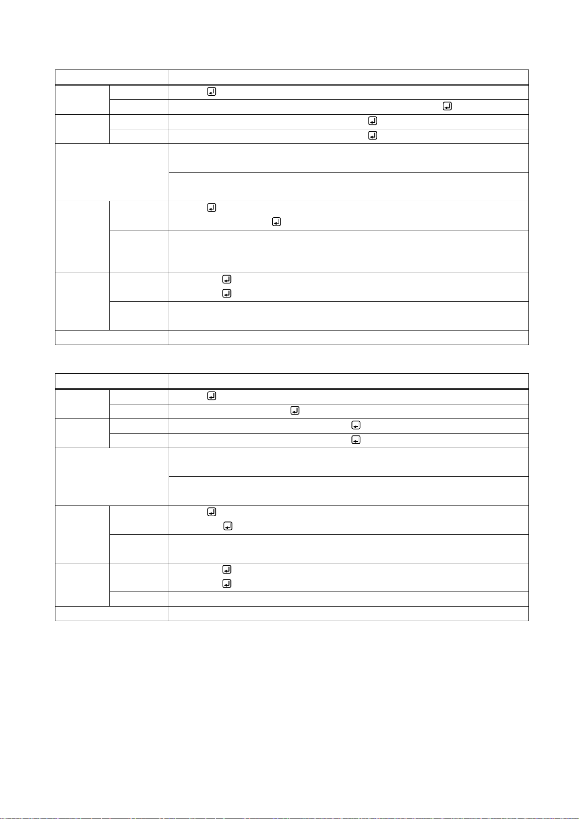
@GID / @SID
Automa t ic dete c tion of input video inte r r uption
Response
@GID, detect_1, detect_2, detect_3, detect_4,
, detect_8
Response
@SID, ch_1, detect _1 (, c h_2, det ec t_2
)
Parameter
detect_1-8: Aut om atic detection
0 = All inputs, 1 = IN1 to 8 = IN8
Getting
Command
@GID
Other inputs: OFF
Setting
Command
@SID,2,0
If input video signal is i nterrupted, not to tur n off the video output instantly.
Remarks
@GIN / @SIN
Signal selection of DVI input connector
Response
@GIN, signal_1, si gnal_2
Setting
Command
@SIN, ch_1, signal_1 ( , ch_2, signal_2)
Response
@SIN, ch_1, signal_1 ( , ch_2, signal_2)
Parameter
signal_1-2: Signal sel ec tion of DVI input connectors (IN7, IN8)
0 =All analog inputs, 7 = IN7, 8 = IN8
IN7 and IN8: Analog input signal
example
Response
@SIN,8,1
Description
Setting IN8 to digital input signal.
Remarks
Getting Command @GID
Setting Command @SID, ch_1, detect _1 (, c h_2, det ec t_2・・・)
・・・
0 = OFF, 1 = ON [Default]
ch_1-8: Input c hannel
・・・
example
Response
@GID,1,1,1,1,1,0,1,1
Description Getting the setting of automati c detec tion of input video interrupt ion.
IN6: If input vi deo si gnal is i nterrupted, the video out put is not turned off instantly .
example
Response
@SID,2,0
Description Setti ng IN2 automatic detecti on to OFF (“0”).
-
Getting Command @GIN
0 = Analog signal, 1 = Digital signal [Default]
ch_1-2: Input c hannel
Getting
example
Command
Response
@GIN
@GIN,0,0
Description Getting the set DVI input signal.
Setting
Command
@SIN,8,1
-
42
Page 43
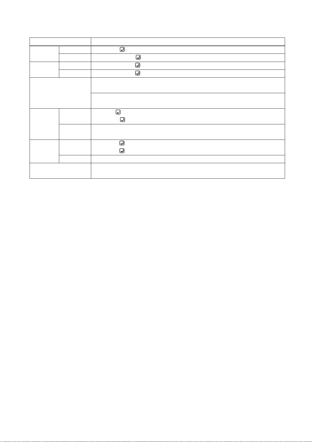
@GIA / @SIA
HDBaseT input long reach mode
Response
@GIA, ch, mode
Response
@SIA, ch, mode
Parameter
ch: Input channel
0 = long reach mode OFF [Default], 1 = long reach mode ON
Getting
Command
@GIA,5
Setting long reach mode of IN5 to OFF.
example
Response
@SIA,6,1
Description
Setting long reach mode of IN6 to ON.
Remarks
If this menu is set to “ON”, resolut ions up to 1080p (24 bit) ar e supported. If it
Getting Command @GIA, ch
Setting Command @SIA, ch, mode
5 = IN5, 6 = IN6 Make sure to set t his menu t o “5” or “6”.
mode: Setting mode
MSD-62 series Command Guide
example
Description Getting long reach mode setting of IN5.
Setting
Response
Command
@GIA,5,0
@SIA,6,1
exceeds 1080p (24 bit), video signal cannot be receiv ed.
43
Page 44
MSD-62 series Command Guide
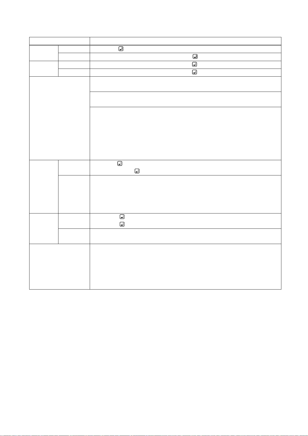
@GFX / @SFX
Fixing se tt i ngs f or in put signa l
Response
@GFX, ch, mode (, aspect, analog, audio)
Response
@SFX, ch, mode (, aspect, analog, audio)
Parameter
ch: Input channel
0 = SELECTED, 1 = ALL FIXED
Available only if t he “mode” is selected to “0” (SELECTED)
example
Response
@GFX, 1,0,1,0,0
Description
Getting setting fixation of each input signal.
Audio input level is disabled.
example
Response
@SFX,2,1
Description
IN2: Fixing settings for each input to the current settings.
Getting Command @GFX ch
Setting Command @SFX, ch, mode (, aspect, analog, audio)
1 = IN1 to 8 = IN8
mode : Setting mode
aspect: Aspect ratio
0 = OFF [Default], 1 = ON(FIXED)
analog: Signal type of analog input (For digital input , select “0”)
0 = OFF, 1 = ON(FIXED) [Default]
audi : Audio input lev el (For analog input, select “0”)
0 = OFF, 1 = ON(FIXED) [Default]
Getting
Command
@GFX, 1
(For analog inputs)
IN1 aspect rati o: cur r ent sett ing, signal type of analog input: setting of each input
signal.
Setting
Remarks When digital input channel is acquired, “0” is returned for t he Parameter of analog
Command
@SFX,2,1
Completed normally .
signal type. (“0” is an i nv alid v alue.)
When analog input c hannel is acquired, “0” is retur ned for the Parameter of audio
input level. (“0” is an invalid value.)
Input channels IN7 and IN8: digital input/analog input selectable.
【See: @GIN / @SIN Signal selec tion of DVI input connector】
44
Page 45
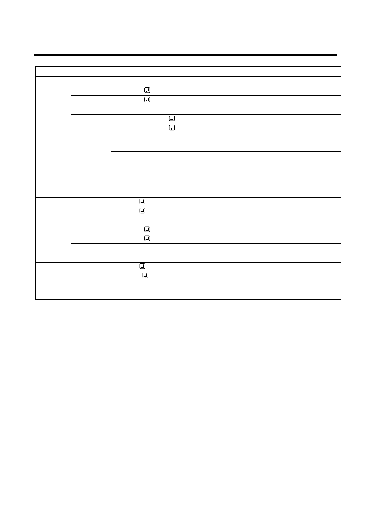
3.3.8 Input timing
@AIS / @AIT
Automatic measurement
Setting
Description
Starting autom atic measurement of the start position and display period.
Command
@AIS, ch
Response
@AIS, ch
Setting
Description
Starting autom atic measurement with a desired aspect r atio.
Response
@AIT, ch (, mode)
7 = IN7, 8 = IN 8
mode: Measurement mode
parameter, “NE XT ASPE CT” m ode will be applied.
example
Response
@AIS,8
Setting
Command
@AIT,8,0
of “4:3”.
Setting
Command
@AIS,8
Remarks
These commands are vali d only if analog RGB/analog YPbPr signal i s input.
Command @ AIT, ch (, mode)
Parameter ch: Input channel
-1 = NEXT ASPECT, 0 = 4:3, 1 = 5:4, 2 = 5:3, 3 = 16:9, 4 = 16:10
If you select “NEXT ASPE CT”, t he next aspect r atio will be selected in order
every time the automatic measurement is executed. If you do not set any mode
MSD-62 series Command Guide
Setting
Description Star ting the automatic measurement of IN8 the start position and display per iod.
example
Description Star ting the automatic measurement of IN8 input timing setting at the aspect ratio
example
Description If the aut om atic measurement fails, an err or i s ret ur ned.
Command
Response
Response
@AIS,8
@AIT,8,0
@ERR,7
45
Page 46
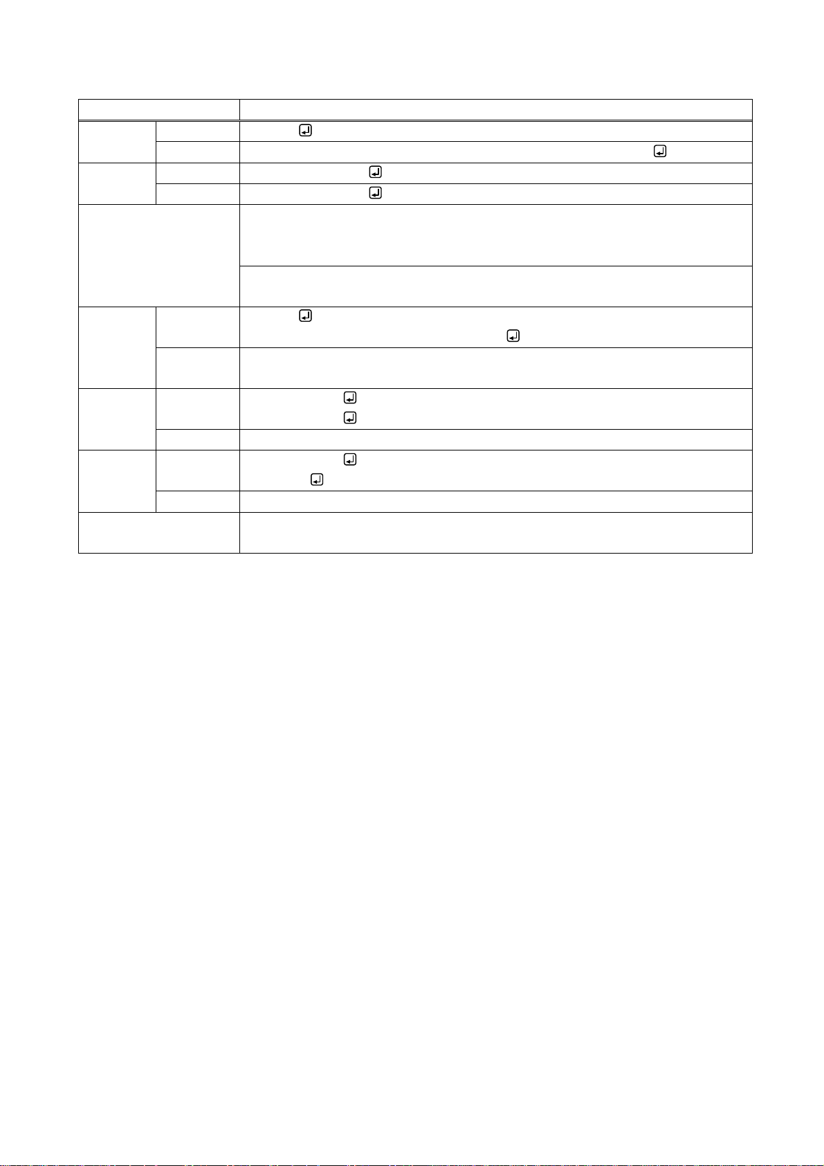
MSD-62 series Command Guide
@GHT / @ SHT
The total number of horizontal dots
Response
@GHT, h_total_1, h_total_2, h_total_3, h_t otal_4,
, h_total_8
Response
@SHT, ch, h_total
Parameter
h_total_1-8 / h_total: The total number of horizontal dots
[Default] depends on i nput signal
ch: Input channel
example
Response
@GHT,2200,2200,0,2640,1344,1792,0,0
“0” is returned to channels without input signal.
Setting
Command
@SHT,8,1344
example
Response
@ERR,3
Description
If analog RGB signal or anal og Y P bPr signal is not input, an error is returned.
Getting Command @GHT
Setting Command @S HT, c h, h_t otal
400 to 4125 (sampli ng bloc k shoul d be 13 M Hz to 162 MHz)
0 =All analog inputs, 7 = IN7, 8 = IN8
Getting
Description Get ting the total number of horizontal dots.
Command
@GHT
・・・
example
Description Setting the total number of IN8 horiz ont al dots to “1344”.
Setting
Remarks Getting command acquires all c hannels’ statuses.
Response
Command
@SHT,8,1344
@SHT,8,1344
Setting commands are valid only if analog RGB/analog YPbPr si gnal is input.
46
Page 47
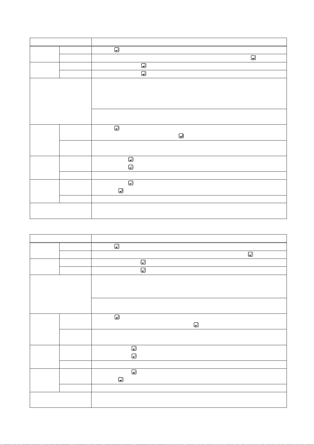
@GHS / @SHS
Horizontal start po sition
Response
@GHS, h_start_1, h_start_2, h_start_3, h_start_4,
, h_start_8
Response
@SHS, ch, h_start
Parameter
h_start_1-8 / h_start : Horizontal start posit ion
0 = All inputs, 1 = IN1 to 8 = IN8
Description
Getting the hori z ontal start position.
example
Response
@SHS,5,296
Description
Setting IN5 horiz ontal start position to 296 dot s.
Setting
Command
@SHS,6,296
@GHD / @SH D
Horizontal display period
Getting
Command
@GHD
Response
@GHD, h_disp_1, h_disp_2, h_disp_3, h_disp_4,
, h_disp_8
Setting
Command
@SHD, ch, h_disp
Response
@SHD, ch, h_disp
0 = All inputs, 1 = IN1 to 8 = IN8
Getting
Command
@GHD
“0” is returned to channels without input signal.
Setting
Command
@SHD,6,1024
If 4K video signal is input, only gett ing commands are vali d.
Getting Command @GHS
Setting Command @SHS, ch, h_start
64 to 2900 (should be [the tot al num ber of horiz ontal dots – horizontal display
period] or less)
[Default] depends on i nput signal
ch: Input channel
MSD-62 series Command Guide
・・・
Getting
example
Command
Response
@GHS
@GHS,192,192,496,0,296,0,378,0
“0” is returned to channels without input signal.
Setting
example
Command
Response
@SHS,5,296
@ERR,3
Description If no signal is input, an error is ret ur ned.
Remarks Setting command is valid only for video signal except for 4K video signal.
If 4K video signal is input, only Get ting commands are available.
・・・
Parameter h_disp_1-8 / h_disp : Horizontal display period
64 to 2900 (should be [the tot al num ber of horiz ontal dots - 64] or less)
[Default] depends on i nput signal
ch: Input channel
example
Response
@GHD,1920,1920,0,1920,1024,1360,0,0
Description Get ting horizontal displ ay period.
Setting
example
Command
Response
@SHD,5,1024
@SHD,5,1024
Description Setting IN5 horizontal displ ay per iod to 1024 dots.
example
Response
@ERR,3
Description If no si gnal is i nput, an error is returned.
Remarks Setting commands: valid only for video si gnal ex c ept for 4K video signal.
47
Page 48
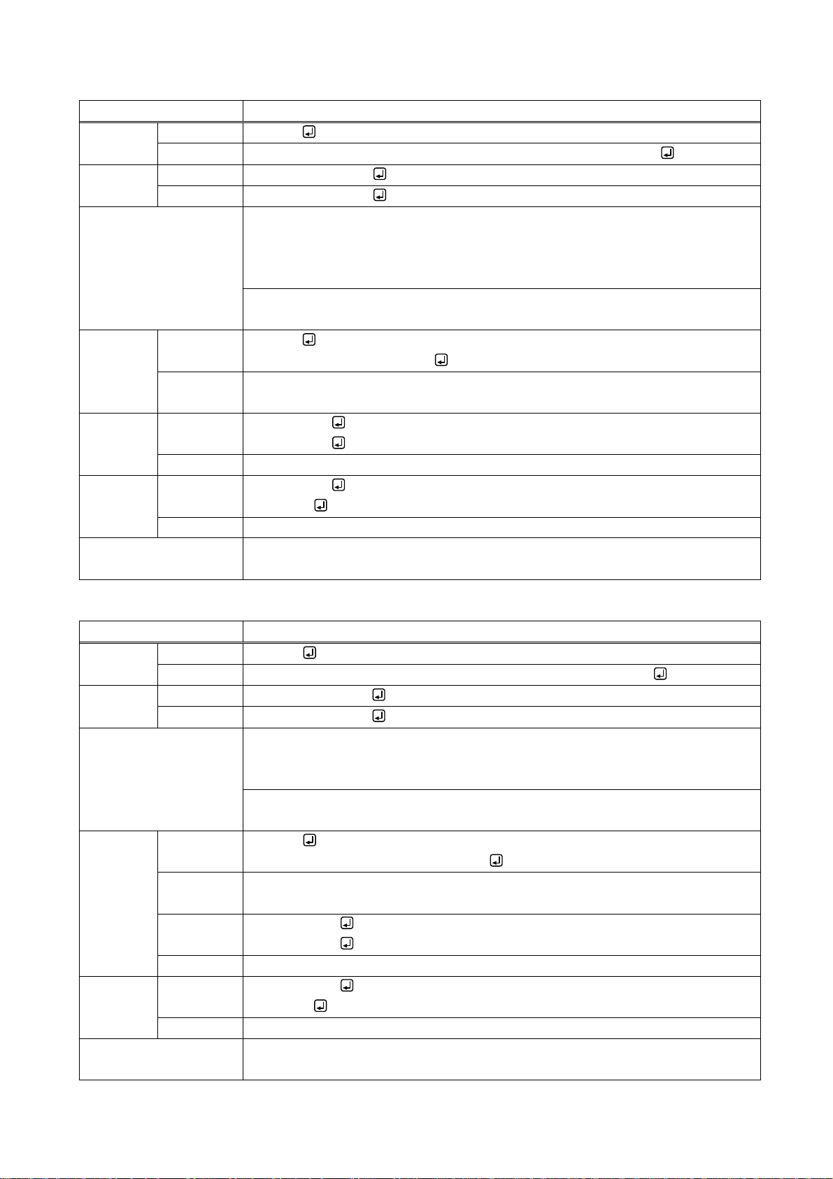
MSD-62 series Command Guide
@GVS / @SVS
Vertical start position
Response
@GVS, v_start_1, v_start_2, v_start_3, v_start_4,
, v_start_8
Response
@SVS, ch, v_start
Parameter
v_start_1-8 / v_start : Vertical start posi tion
0 = All inputs, 1 = IN1 to 8 = IN8
Description
Getting the vertical start position.
example
Response
@SVS,5,35
Description
Setting IN5 vertic al star t position to 35 lines.
Setting
Command
@SVS,6,35
@GVD / @SVD
Vertical display period
Getting
Command
@GVD
Response
@GVD, v_disp_1, v_disp_2, v_disp_3, v_disp_4,
, v_disp_8
Setting
Command
@SVD, ch, v_disp
Response
@SVD, ch, v_disp
0 = All inputs, 1 = IN1 to 8 = IN8
Getting
Command
@GVD
“0” is returned to channels without input signal.
Setting
Command
@SVD,5,768
If 4K video signal is input, only gett ing commands are valid.
Getting Command @GVS
Setting Command @SVS, ch, v_start
10 to 2048 (should be [the tot al num ber of ver tical lines - vertical display
period] or less)
[Default] depends on i nput signal
ch: Input channel
・・・
Getting
example
Command
Response
@GVS
@GVS,40,0,40,40,35,0,24,0
“0” is returned to channels without input signal.
Setting
example
Command
Response
@SVS,5,35
@ERR,3
Description If no signal is input, an error is ret ur ned.
Remarks Setting commands: v alid only for video signal except for 4K video signal.
If 4K video signal is input, only gett ing commands are valid.
・・・
Parameter v_disp_1-8 / v_disp: V er tical display period
10 to 2048 (should be [the tot al num ber of ver tical lines - 10] or less)
[Default] depends on i nput signal
ch: Input channel
example
Response
@GVD,0,1080,1080,900,768,0,900,0
Description Get ting vertical display peri od.
Setting
example
Command
Response
@SVD,5,768
@SVD,5,768
Description Setting IN5 vertical displ ay period to 768 lines.
example
Response
@ERR,3
Description If no si gnal is i nput, an error is returned.
Remarks Setting commands: vali d only for vi deo si gnal ex c ept for 4K video signal.
48
Page 49
@GIS / @SIS
Automatic measurement of start position
Response
@GIS, mode_1, mode_2
Response
@SIS, ch, mode
Parameter
mode_1-2 / mode: Automatic measurement
0 = All analog inputs, 7 = IN7, 8 = IN8
Description
Getting the setting of Automatic measurement of the start posi tion.
example
Response
@SIS,8,1
Description
Setting signal that is currently input from IN8 to “1” (Current input signal is not
returned.
@GSM / @SSM
Automatic measurement when unregistered signal is input
Getting
Command
@GSM
Response
@GSM, mode
Setting
Command
@SSM, mode
Response
@SSM, mode
Automatic measurement is set to “1” (Execute).
Setting
Command
@SSM,1
input.
Remarks
Getting Command @GIS
Setting Command @SIS, ch, mode
0 = All inputs from this input channel are not measured automatically.
1 = Current input signal is not measured automatically.
2 = Current input signal is measured automatically . [Default]
ch: Input channel
MSD-62 series Command Guide
Getting
example
Command
Response
@GIS
@GIS,0,2
IN7: not measured automatically, IN8: measured automatically.
Setting
Command
@SIS,8,1
measured autom atically).
Remarks These commands are only for analog input.
IN7 and IN8 are available only if “0” (Anal og si gnal) is selected for “@GIN / @SIN
Signal selection of D VI input connec t or
”. If “1” (Digital signal) is selected, “-1” is
Parameter mode: Automatic measurement
0 = Not execute, 1 = Execute [Default]
Getting
example
Command
Response
@GSM
@GSM,1
Description Getting the set automatic measurement mode when unregistered signal is input.
example
Response
@SSM,1
Description Setti ng the automatic measurement t o be execut ed when unregi ster ed si gnal is
-
49
Page 50
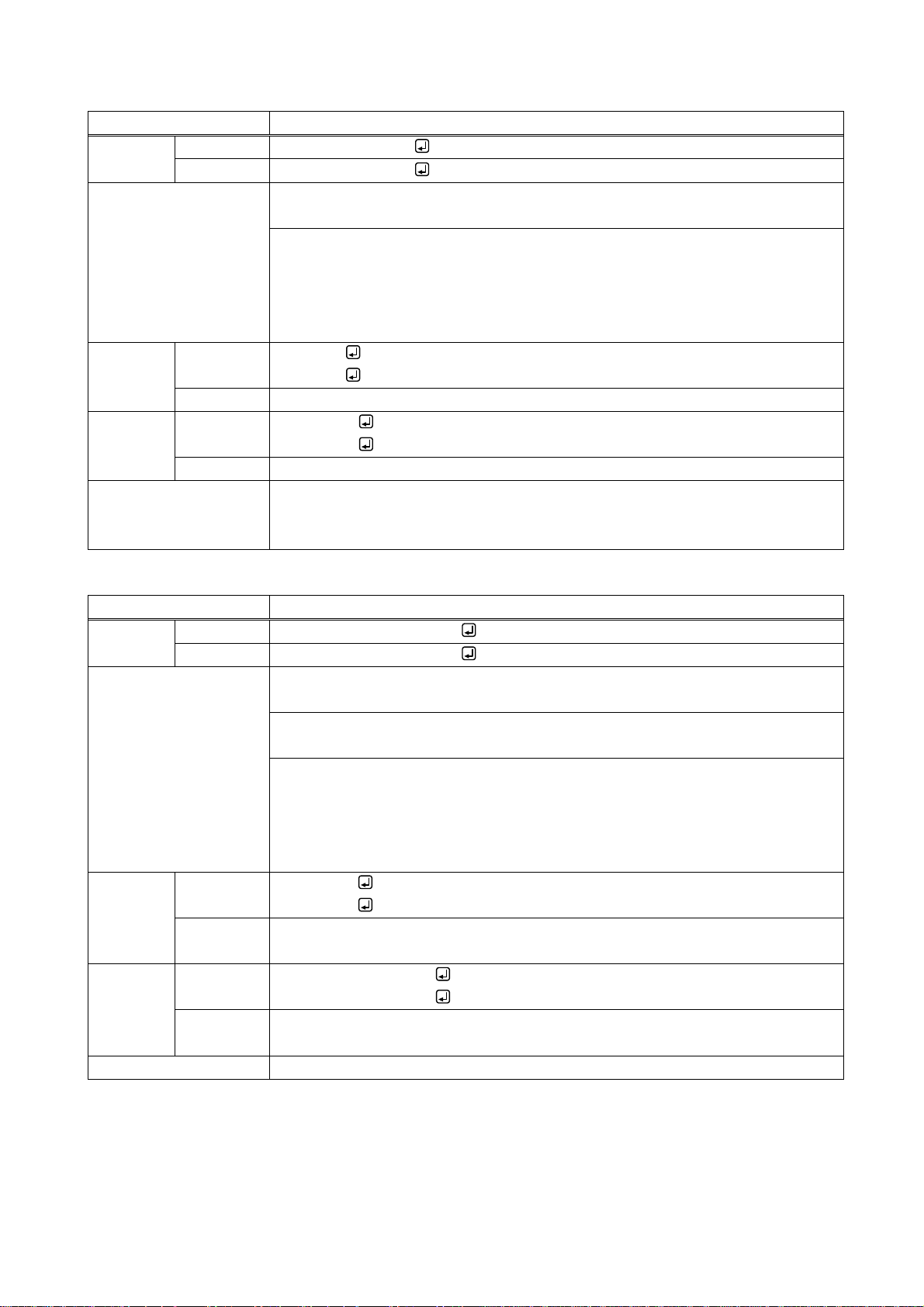
MSD-62 series Command Guide
@RTT
Loading device data
Response
@RTT, ch (, table)
1 = IN1 to 8 = IN8
example
Response
@RTT,1
Description
Setting IN6 input timings to the values saved in the device table 2.
Remarks
This command is valid only if signal is input.
registered.
@STT
Registering device data
Response
@STT, ch, table (, name)
1 to 99
name: D evice table nam e
automatic ally as the dev ic e table name.
example
Response
@STT,1,2
Description
Saving IN1 input timi ng setting in device table 2 without edi ting the device table
example
Response
@STT,1,2,XGA 60Hz
Description
Saving the current IN8 input timing setting in device table 2 with the name of
Remarks
This command is valid only if analog RGB / YPbPr signal is input.
Setting Command @RTT, ch (, table)
Parameter ch: I nput channel
table: Device table
1 to 99 (Registered devic e data),
100 to 100+n (Preset devic e data. ”n” varies depending on i nput signal,
but 0 for most cases.)
Only for analog input, specify the device table.
Setting
Command
@RTT,1
Description Rec onfiguring IN1 input timing setting to the value det ected aut om atically.
Setting
example
Command
Response
@RTT,6,2
@RTT,6,2
For analog input, t his comm and is valid only if the device data of input si gnal is
Setting Command @STT, ch, table (, name)
Parameter ch: I nput channel
1 = IN1, 2 = IN2
table: Device table
Up to 14 characters fr om 20 to 7D of ASCII code.
You can skip “Device table name”. If you skip it, onl y input timing setting is saved.
However, if no device table name is currently sav ed, the resolution is saved
Setting
Command
@STT,1,2
name.
Setting
Command
@STT,1,2,XGA 60Hz
“XGA 60Hz”.
50
Page 51
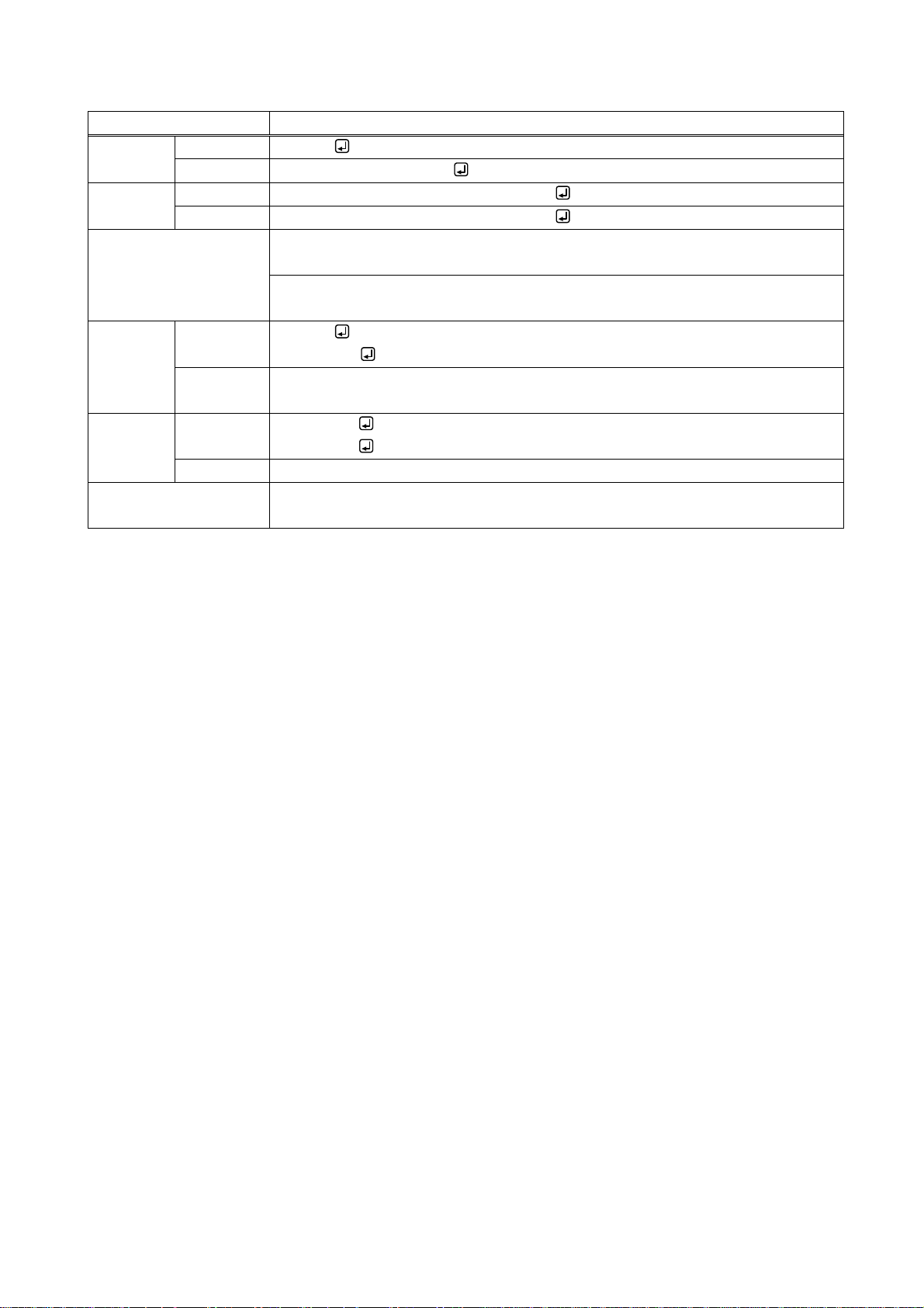
@GTK / @STK
Tracking
Response
@GTK, track_1, track_2
Response
@STK, ch_1, track_1 (, ch_2 , t r ac k _2)
Parameter
track_1-2: Tracking
0 = All analog inputs, 7 = IN7, 8 = IN8
Getting
Command
@GTK
If no analog RGB / YPbPr signal is i nput, “0” i s ret ur ned.
example
Response
@STK,8,4
Description
Setting IN8 tracki ng to “4”.
Remarks
This command is valid only if analog RGB / YPbPr signal is input. If “1” (Digital
Getting Command @GTK
Setting Command @STK, ch_1, track_1 (, ch_2 , t r ac k _2)
0 to 63 [Default] 0
ch_1-2: Input c hannel
MSD-62 series Command Guide
example
Description Getting the set tracking.
Setting
Response
Command
@GTK,4,0
@STK,8,4
signal) is selected, “-1” is returned.
51
Page 52
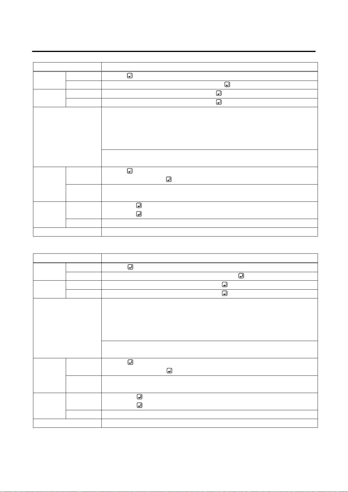
MSD-62 series Command Guide
@GEQ / @SEQ
Output equalizer
Getting
Command
@GEQ
Response
@GEQ, level_1, level_2, level_3, …, level_8
Command
@SEQ, ch_1, level_1 (, ch_2, level_2
)
Response
@SEQ, ch_1, level_1 (, ch_2, level_2
)
0 = All HDMI outputs, 1 = OUT1A to 8 = OUT8A
Getting
Command
@GEQ
OUT2A: OFF, ot her output channels: HIGH
example
Response
@SEQ,1,0
Description
Setting the OUT1A output equalizer to OFF.
Remarks
This command is only for HDMI output connectors.
@GDM / @SDM
Output mode
Setting
Command
@SDM, ch_1, mode_1 (, ch_2, mode_2
)
Parameter
mode_1-8: Output mode
3 = HDMI YCbCr4:4:4 MODE [Default]
ch_1-8: Output channel
Setting
Command
@SDM,1,3
3.3.9 Output settings
Setting
Parameter level_1-8: Output mode
0 = OFF [Default],
1 = LOW,
2 = MIDDLE,
3 = HIGH
ch_1-8: Out put channel
example
Description Getting the set output mode.
Setting
Response
Command
@GEQ,3,0,3,3,3,3,3,3
@SEQ,1,0
・・・
・・・
Getting Command @GDM
Response @GDM, mode_1, mode_2, mode_3, ・・・, mode_8
・・・
Response @SDM, ch_1, mode_1 (, ch_2, mode_2・・・)
0 = DVI MODE,
1 = HDMI RGB MODE,
2 = HDMI YCbCr4:2:2 MODE,
0 = All outputs, 1 = OUT1 to 8 = OUT8
Getting
example
Description Getting the set output mode.
example
Description Setti ng the OUT1 output mode to “HDMI YCbCr4: 4: 4 MODE”
Remarks -
Command
Response
Response
@GDM
@GDM,3,0,3,3,3,3,3,3
OUT2: DVI MODE, other output channels: HDM I YCbCr4:4:4 MODE
@SDM,1,3
52
Page 53
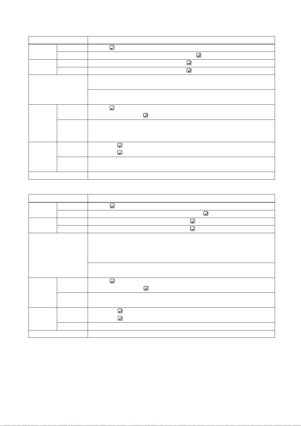
@GUY / @SUY
Synchro nous sig na l ou t p ut when no vide o s ig na l is input
Response
@GUY, sync_1, sync_2, sync_3,
, sync_8
Response
@SUY, ch_1, sync_1 (, ch_2, sync_2
)
Parameter
sync_1-8: Synchronous signal output
0 = All outputs, 1 = OUT1 to 8 = OUT8
Getting
Command
@GUY
Other output channels: synchronous signal is not output.
Setting
Command
@SUY,1,1
input).
Remarks
@GBO / @SBO
Output video when no vid e o s ignal i s not input
Response
@GBO, video_1, video_2, video_3,
, video_8
Setting
Command
@SBO, ch_1, video_1 (, ch_2, v ideo_2
)
Response
@SBO, ch_1, video_1 (, ch_2, v ideo_2
)
Parameter
video_1-8: Output video when no vi deo si gnal is not input
0 = All outputs, 1 = OUT1 to 8 = OUT8
example
Response
@GBO,1,0,0,0,0,0,0,0
example
Response
@SBO,1,1
Description
Setting OUT1 to output blue when no vi deo si gnal is input.
Remarks
Getting Command @GUY
・・・
Setting Command @SUY, ch_1, sync_1 (, ch_2, sync_2・・・)
・・・
0 = Not output, 1 = Output [Default]
ch_1-8: Output channel
MSD-62 series Command Guide
example
Response
@GUY,1,0,0,0,0,0,0,0
Description Getting synchronous signal out put when no video signal is input.
OUT1: synchronous signal is output.
example
Response
@SUY,1,1
Description Setti ng OUT1 to “1” (synchronous signal i s output even if video signal is not
-
Getting Command @GBO
・・・
・・・
・・・
0 = Black,
1 = Blue [Default],
2 = Background color
ch_1-8: Output channel
Getting
Command
@GBO
Description Getting the output video when no video signal is input.
OUT1: blue screen, other output channels: blac k screen
Setting
Command
@SBO,1,1
-
53
Page 54
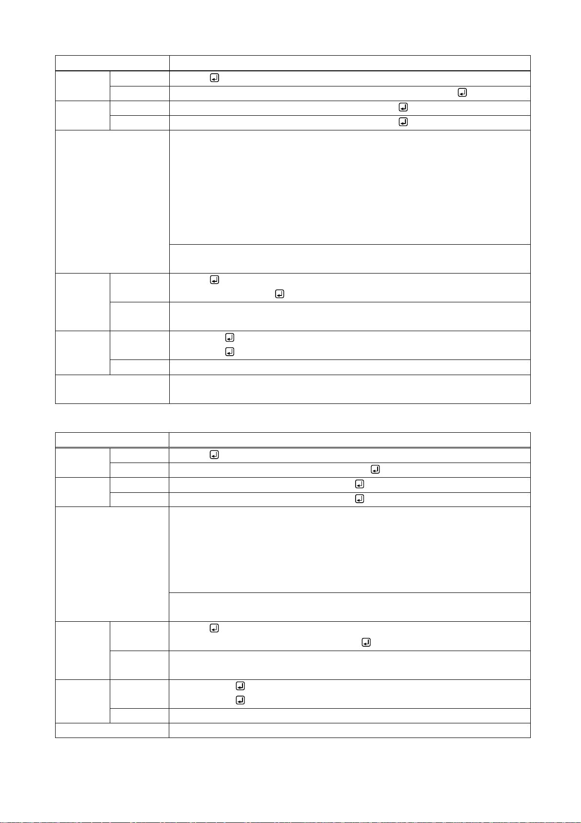
MSD-62 series Command Guide
@GFF / @SFF
Video switching effect
Getting
Command
@GFF
Command
@SFF, ch_1, switching_1 (, ch_2, switching_2
)
6 = BOTTOM→TOP WIPE
0 = All outputs, 1 = OUT1 to 8 = OUT8
OUT1 to OUT4: CUT, OUT5 to OUT8: FADE OU T /IN
Setting
Command
@SFF,1,1
combination mode is enabled.
@GFT / @SFT
Video switching speed
Getting
Command
@GFT
Response
@GFT, time_1, time_2, time_3,
, time_8
Setting
Command
@SFT, ch_1, time_1 (, ch_2, time_2
)
Response
@SFT, ch_1, time_1 (, ch_2, time_2
)
390 ms.)
ch_1-8: Output channel
example
Response
@GFT,400,400,400,400,350,350,350,350
Description
Getting the set switchi ng speed of video input channel.
OUT1 to OUT4: 400 ms, OUT5 to OUT8: 350 ms
Response @GFF, switching_1, switching_2, switching_3, ・・・, switching_8
Setting
Response @SFF , ch_1, switching_1 (, ch_2, switchi ng_2・・・)
Parameter switching_1-8: Video switching eff ec t
0 = CUT,
1 = FADE OUT/IN,
2 = FREEZE + FADE OUT/IN [Default],
3 = LEFT→RIGHT WIPE,
4 = RIGHT→LEFT WIPE,
5 = TOP→BOTTOM WIPE,
ch_1-8: Output channel
・・・
Getting
example
Command
Response
@GFF
@GFF,0,0,0,0,1,1,1,1
Description Getting input channel switching effect.
example
Response
@SFF,1,1
Description Setti ng OUT1 switching effect to FADE OUT/IN.
Remarks An error occurs if this menu is set to one of “3” to “6” (WIPE) while video
・・・
・・・
・・・
Parameter time_1-8: Switching speed
100 = 0.1 sec. to 2000 = 2 sec.
[Default] 350 = 0.35 sec.
Set the value by 10 ms. If you set a value other than 0 for the lower 1 digits, these
values will be rounded down. (For example, if you set it to 395, the speed is set to
0 = All outputs, 1 = OUT1 to 8 = OUT8
Getting
Setting
example
Command
Command
Response
@GFT
@SFT,1,400
@SFT,1,400
Description Setting OUT1 switching tim e to 400 ms.
Remarks -
54
Page 55
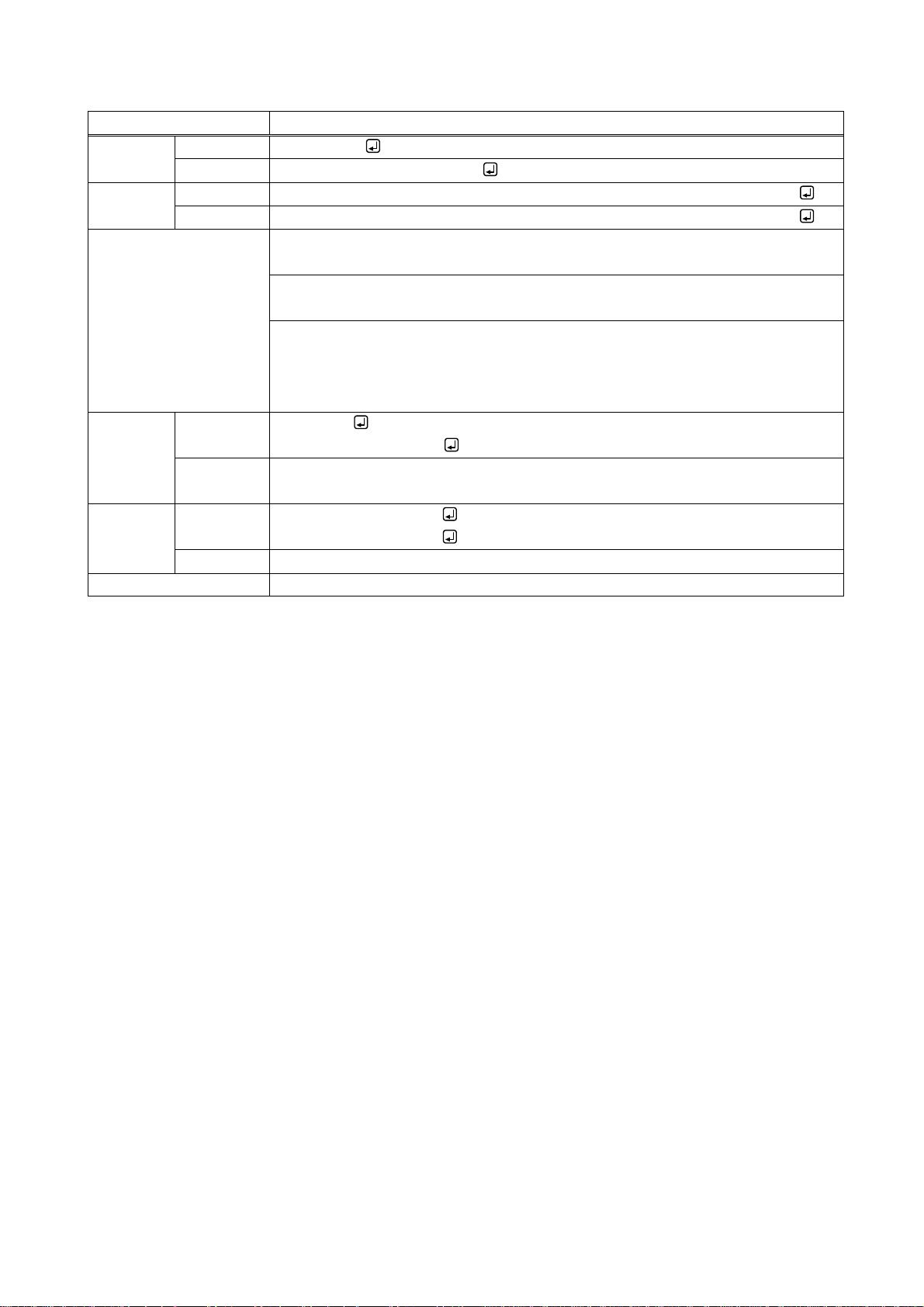
MSD-62 series Command Guide
@GWC / @SWC
Wipe color
Response
@GWC, ch, red, green, blue
Response
@SWC, ch_1, red_1, green_1, blue_1 (, ch_2, red_2, green_2, blue_2
)
Parameter
ch: Output channel
0 = All outputs, 1 = OUT1 to 8 = OUT8
red / red_1-8 : Wipe color (Red)
Getting
Command
@GWC,1
RGB: 255 (white)
Setting
Command
@SWC,1,255,255,255
Getting Command @GWC, ch
Setting Command @SWC, ch_1, red_1, green_1, blue_1 (, ch_2, red_2, green_2, blue_2・・・)
・・・
1 = OUT1 to 8 = OUT8
ch_1-8: Output channel
green / green_1-8 : Wipe color (Green)
blue / blue_1-8 : Wipe color (Blue)
0 to 255 [Default] 0 (black )
example
Description Getting the set wipe color of OUT1.
example
Description Setti ng the wipe colors (RGB) of OUT1 to “255” (white).
Remarks -
Response
Response
@GWC,1,255,255,255
@SWC,1,255,255,255
55
Page 56
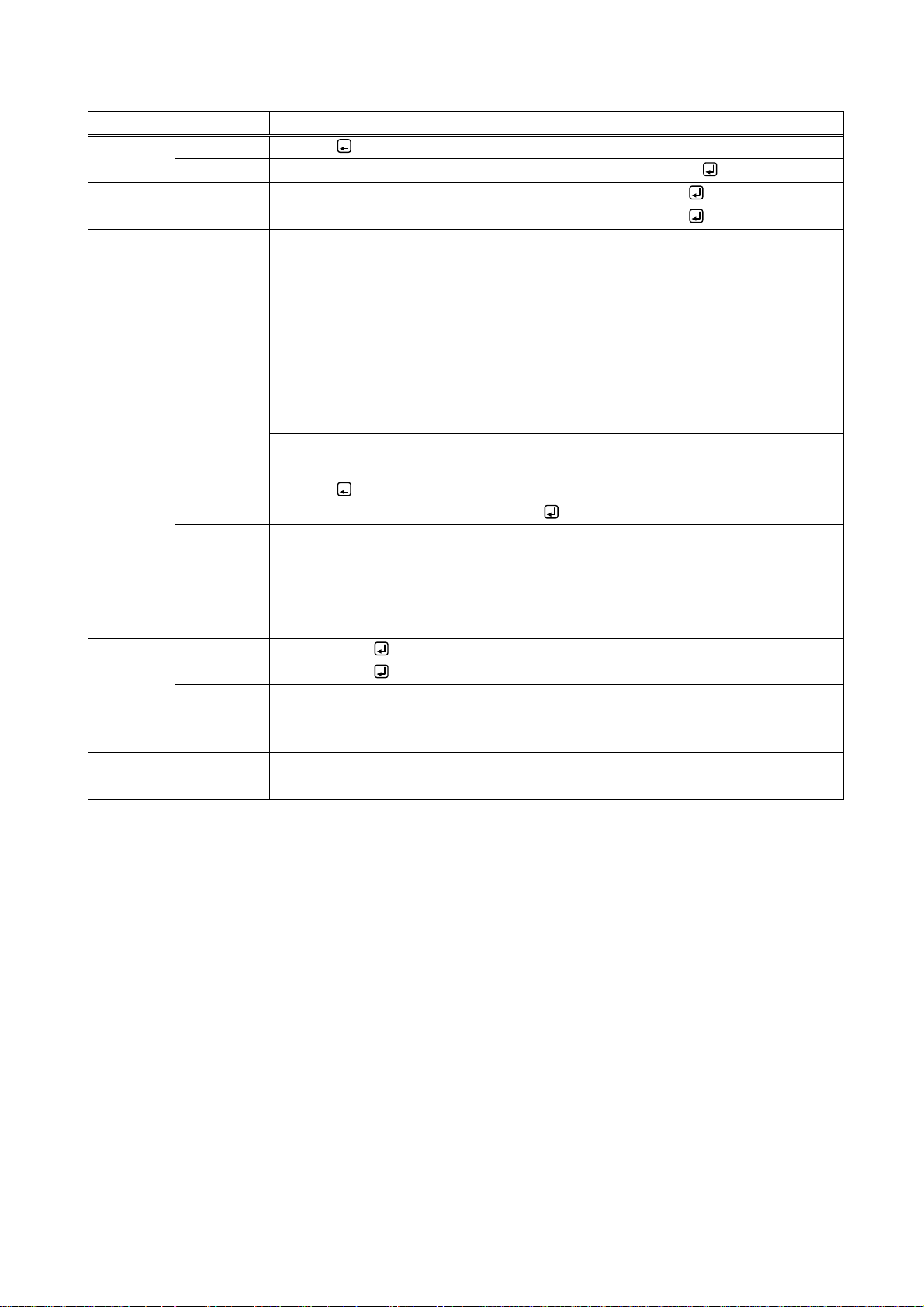
MSD-62 series Command Guide
@GVO / @SVO
HDMI / HDBaseT output
Response
@GVO, out_1A, out_1B, out_2A, out2B, …, out_8A, out_8B
Response
@SVO, ch_1, out_1A, out _1B (, c h_2, out _2A , out_2B
)
Parameter
out_1A-8A: HDMI (OUT A) output video
signal
0 = All outputs, 1 = OUT1 to 8 = OUT8
Getting
Command
@GVO
the HDBaseT output c onnec tors output video.
example
Response
@SVO,1,1,0
and HDBaseT output connect or.
Getting Command @GVO
Setting Command @S VO, ch_1, out_1A, out_1B (, ch_2, out_2A , out_2B・・・)
・・・
out_1B-8B: HDBaseT (OUT B) output video
0 = Not output, 1 = Output
[Default]: HDMI output signal is output from HDMI output c onnec tor,
HDBaseT signal i s not output from HDB aseT output connector
(All output channels)
* The MSD cannot output signals from HDMI connector and HDBaseT
connector simultaneously. Ensure to set onl y one connector to output
ch_1-8: Output channel
example
Description Getting the video output c onnec tors.
Setting
Description Setting video output connector.
Remarks An error occurs if the same parameter is issued to both HDMI output connector
Response
Command
@GVO,1,0,1,0,1,0,1,0,0,1,0,1,0,1,0,1
OUT1 to OUT4: The HDMI output connectors output v ideo while
the HDBaseT output c onnec tors do not output video.
OUT5 to OUT8: The HDMI output connector s do not output v ideo while
@SVO,1,1,0
OUT1: The HDMI output connector outputs video and
the HDBaseT output c onnec tor does not output video.
56
Page 57
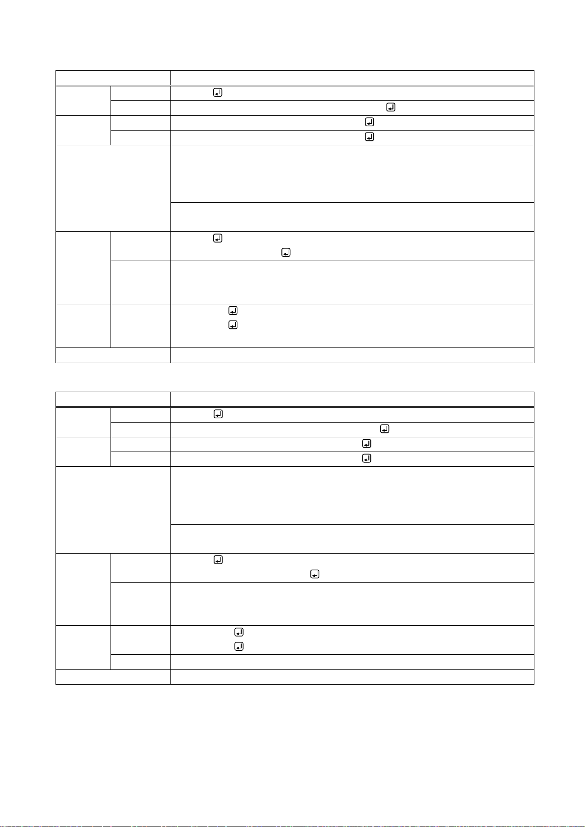
@GEN / @SEN
HDCP output
Response
@GEN, hdcp_1, hdcp_2, hdcp_3,
, hdcp_8
Response
@SEN, ch_1, hdcp_1 (, ch_2, hdcp_2
)
Parameter
hdcp_1-8: HDCP output
0 = All outputs, 1 = OUT1 to 8 = OUT8
Description
Getting the set HDCP output.
Other output channels: HDCP is always encrypted.
Setting
Command
@SEN,1,1
@GHR / @SHR
The number of HDCP retries
Command
@GHR
1 to 100 = Retry for the desired number of retries
ch_1-8: Output channel
0 = All outputs, 1 = OUT1 to 8 = OUT8
Getting
Command
@GHR
example
Response
@SHR,4,10
Description
Setting OUT4 to retry for up t o 10 times.
Getting Command @GEN
・・・
Setting Command @SEN, ch_1, hdcp_1 (, ch_2, hdcp_2・・・)
・・・
0 = HDCP is encrypted only if input signal is with HDCP,
1 = HDCP is always encrypted. [Default],
2 = HDCP is not encrypted.
ch_1-8: Output channel
MSD-62 series Command Guide
Getting
example
Command
Response
@GEN
@GEN, 1,1,1,1,1,1,1,0
OUT8: HDCP is encrypted only if input signal is with HDCP.
example
Response
@SEN,1,1
Description Setti ng OUT1 to “1” (HDCP is always encrypted).
Remarks -
Getting
Response @GHR, retry_1, retry_2, retry_3, ・・・, retry_8
Setting Command @SHR, ch_1, retry_1 (, ch_2, retry_2・・・)
Response @SHR, ch_1, retry_1 (, ch_2, retry_2・・・)
Parameter retry_1-8: The number of retir es
-1 = Retry until succeed [Default],
0 = Not retry,
example
Response
@GHR, -1,-1,-1,-1,-1,-1,-1,10
Description Getting the set number of HDCP retires.
OUT8: Retry for up to 10 times.
Other output channels: continue to retry until succeed.
Setting
Command
@SHR,4,10
Remarks -
57
Page 58
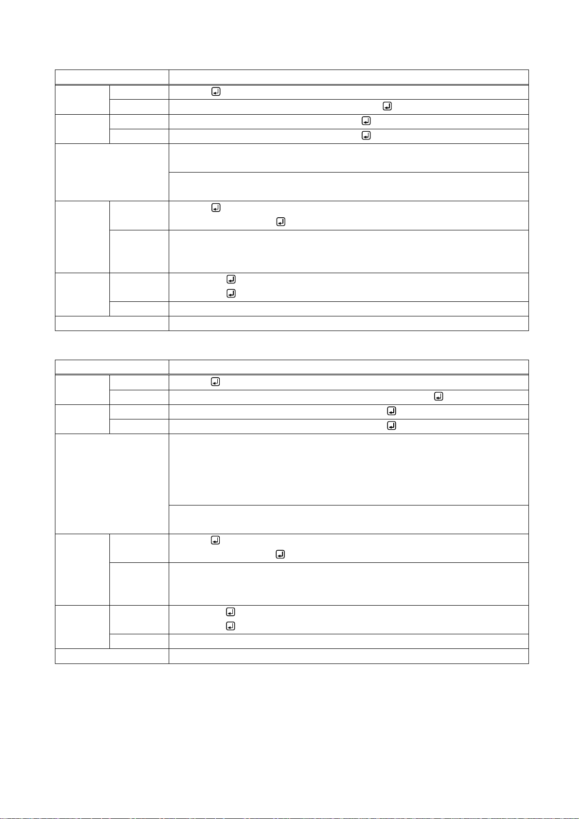
MSD-62 series Command Guide
@GDC / @SDC
Deep Color
Response
@GDC, color_1, color_2, color_3,
, color_8
Response
@SDC, ch_1, color_1 (, ch_2, color_2
)
Parameter
color_1-8: Color depth
0 = All outputs, 1 = OUT1 to 8 = OUT8
Getting
Command
@GDC
Other output channels: 30-BIT COLOR
Setting
Command
@SDC,1,0
@GCE / @SCE
CEC connection
Command
@GCE
Response
@SCE, ch_1, connect_1 (, ch_2, connect_2
)
0 = All outputs, 1 = OUT1 to 8 = OUT8
example
Response
@GCE,4,0,0,0,0,0,0,0
Other output channels: not connected.
Setting
Command
@SCE,1,4
Getting Command @GDC
・・・
Setting Command @SDC, ch_1, color_1 (, ch_2, color_2・・・)
・・・
0 = 24-BIT COLOR [Default], 1 = 30-BIT COLOR
ch_1-8: Output channel
example
Response
@GDC,1,1,0,1,1,1,1,1
Description Getting the set color depth.
OUT3: 24-BIT COLOR,
example
Response
@SDC,1,0
Description Setti ng OUT1 deep color to 24-BIT COLOR.
Remarks -
Getting
Response @GCE, connect_1, connect_2, connect_3, ・・・, connect_8
Setting Command @SCE, ch_1, connect_1 (, ch_2, connect_2・・・)
・・・
Parameter connect_1-8: CEC connection
0 = Not connected [Def ault] , 1 = Selected video input channel,
2 = Input channel1, 3 = Input channel2,
4 = Input channel3, 5 = Input channel4,
6 = Input channel5, 7 = Input channel8
ch_1-8: Output channel
Getting
Command
@GCE
Description Getting the set CEC connection.
OUT1: connecting to input channel3,
example
Response
@SCE,1,4
Description Setti ng OUT1 CEC connection to Input channel 3.
Remarks -
58
Page 59
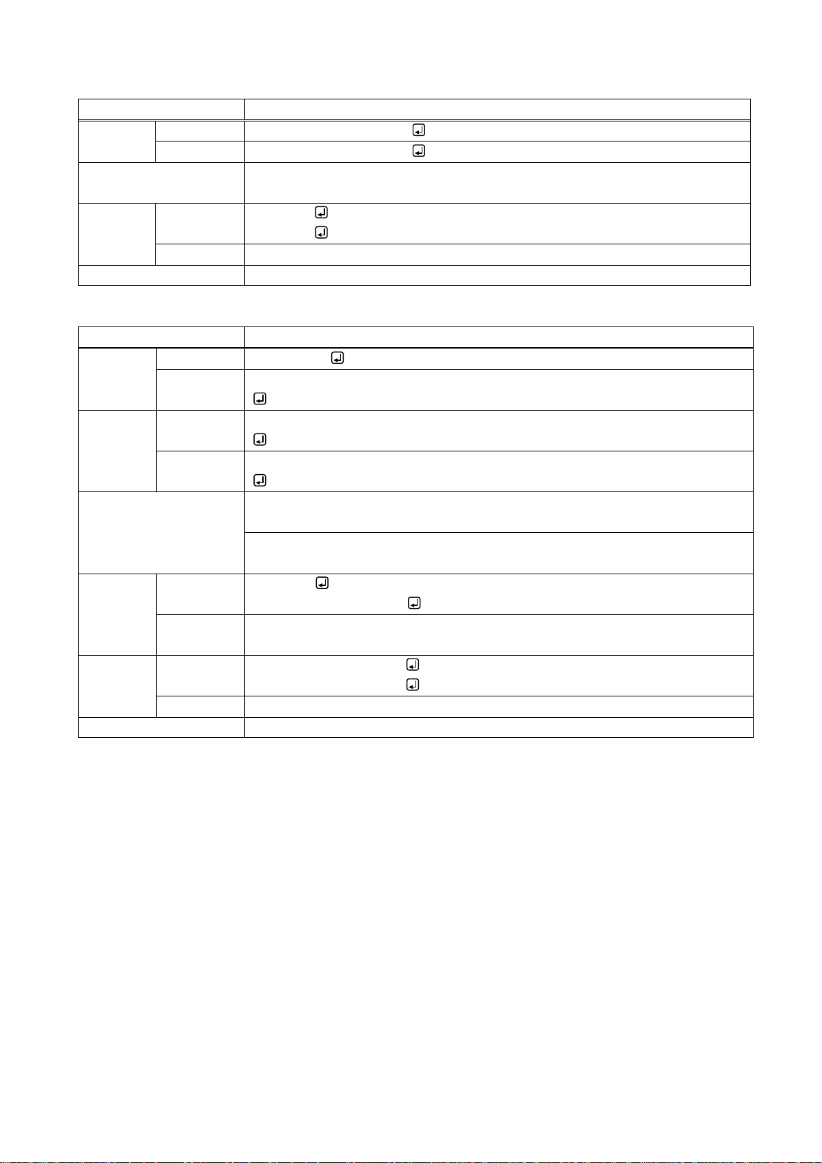
@HAU
HDCP re-encryption
Response
@HAU, ch_1 (, ch_2
)
0 = All outputs, 1 = OUT1 to 8 = OUT8
example
Response
@HAU,1
Description
Setting OUT1 to re-encry pt HDCP.
Remarks
@G AU / @ SAU
Priority of input channel automatic switching ( O FF to ON)
Getting
Command
@GAU, out
Response
@SAU, out_1, in1_priority, in2_priority
, in8_priority (, out_2, in1_priority
)
0 = All outputs, 1 = OUT1 to 8 = OUT8
Getting
Command
@GAU,1
IN1>IN2>
>IN8.
Setting
Command
@SAU,1,8,7,6,5,4,3,2,1
Setting Command @HAU, ch_1 (, ch_2・・・)
・・・
Parameter ch_1-8: Output channel
MSD-62 series Command Guide
Setting
Setting Command @SAU, out_1, in1_priority, in2_priority・・・, in8_priority (, out_2, in1_priority・・・)
Parameter out, out_1-8: Output channel
in1_priority-in8_priority: Priority
example
Description Get ting the set priority of OUT1’s autom atic switching.
Command
Response @GAU, out, in1_priority, in2_priority, in3_priority, in4_priority, ・・・, in8_priority
Response
@HAU,1
-
・・・
0 = OFF, 1 = priorit y (high) to 8 = priority (low)
@GAU,1,1,2,3,4,5,6,7,8
・・・
・・・
example
Description Setting the priority of OUT1’s autom atic switching to IN8>I N7>・・・>IN1.
Remarks -
Response
@SAU,1,8,7,6,5,4,3,2,1
59
Page 60
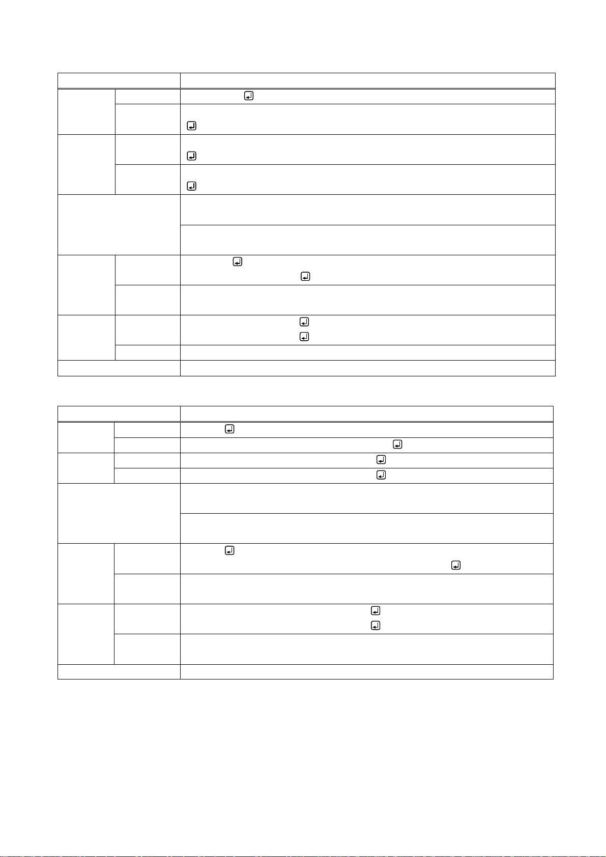
MSD-62 series Command Guide
@GOF / @S OF
Priority of input channel automatic switching (ON to OFF)
Response
@GOF, out, in1_priority, in2_priority, in3_priority, in4_priority,
, in8_priority
Response
@SOF, out_1, in1_priority, in2_priority
, in8_priorit y (, out_2, in1_priority
)
0 = All outputs, 1 = OUT1 to 8 = OUT8
example
Response
@GOF,1,1,2,3,4,5,6,7,8
IN1>IN2>
>IN8
Setting
Command
@SOF,1,8,7,6,5,4,3,2,1
@GMT / @SMT
Masking time after automatic switching of input channel
Command
@GMT
0 = 0 sec. to 999999 = 999.999 sec. [Default] 0 sec.
ch_1-8: Output channel
OUT1 to OUT4: 2000 ms (2 sec.), OUT5 to OUT8: 10000 ms (10 sec.)
Setting
Command
@SMT,1,2000,2,2000,3,10000,4,10000
(10 sec.) for OUT3 and OUT4.
Remarks
Getting Command @GOF, out
・・・
Setting Command @SOF, out_1, in1_priority , in2_priority・・・, in8_pri ori ty (, out_2, in1_priority・・・)
・・・
Parameter out, out_1-8: Output channel
in1_priority-in8_priority: Priority
0 = OFF, 1 = priorit y (high) to 8 = priority (low)
Getting
Command
@GOF,1
Description Get ting the set priority of OUT1’s automatic switching.
・・・
example
Response
@SOF,1,8,7,6,5,4,3,2,1
Description Setting the priority of OUT1’s autom atic switching to IN8>I N7>・・・>IN1.
Remarks -
Getting
Response @GMT, time_1, time_2, time_3, ・・・, time_8
Setting Command @SMT, ch_1, time_1 (, ch_2, time_2・・・)
Response @SMT, ch_1, time_1 (, ch_2, time_2・・・)
Parameter time_1-8 : Masking time
・・・
0 = All outputs, 1 = OUT1 to 8 = OUT8
Getting
example
Command
Response
@GMT
@GMT,2000,2000,2000,2000,10000,10000,10000,10000
Description Getting the set masking time aft er autom atic switching of input channel.
example
Response
@SMT,1,2000,2,2000,3,10000,4,10000
Description Setting the masking time to 2000 ms. (2 sec.) for OUT1 and OUT2, 10000 ms.
-
60
Page 61
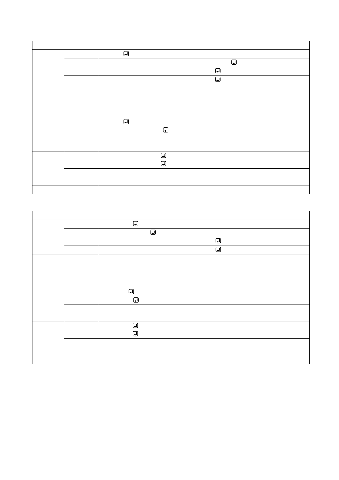
@G AD / @ SAD
Channel switching mode for input channel automatic switching
Response
@GAD, mode_1, mode_2, mode_3,
, mode_8
Response
@SAD, ch_1, mode_1 (, ch_2, mode_2
)
Parameter
mode_1-8 : Channel switchi ng m ode
0 = All outputs, 1 = OUT1 to 8 = OUT8
Getting
Command
@GAD
OUT1 to OUT4: V&A, OUT5 to OUT8: AUDIO
example
Response
@SAD,1,2,2,2,3,0,4,0
@GOA / @ SOA
HDBaseT output long reach mode
Command
@GOA, ch
Response
@SOA, ch_1, mode_1 (, ch_2, mode_2
)
0 = long reach mode OFF [Default], 1 = long reach mode ON
ch_1-8: Output channel
example
Response
@GOA,1,0
Description
Getting long reach m ode setting of OUT1B.
Setting
Command
@SOA,1,1
exceeds 1080p (24 bit), signals cannot be receiv ed.
Getting Command @GAD
・・・
Setting Command @SAD, ch_1, mode_1 (, ch_2, mode_2・・・)
・・・
0 = VIDEO, 1 = AUDIO, 2 = V&A [Default]
ch_1-8: Output channel
MSD-62 series Command Guide
example
Response
@GAD,2,2, 2,2,1,1,1,1
Description Getting the set channel switching mode to:
Setting
Command
@SAD,1,2,2,2,3,0,4,0
Description Setti ng the channel switching mode t o:
OUT1 and OUT2: V&A, OUT3 and OUT4: VIDEO
Remarks -
Getting
Response @GOA, ch, mode
Setting Command @SOA, ch_1, mode_1 (, ch_2, mode_2・・・)
・・・
Parameter mode_1-8: Setting mode
0 = All outputs, 1 = OUT1B to 8 = OUT8B
Getting
Command
@GOA,1
OUT1B: Long reach mode is set to OFF
example
Response
@SOA,1,1
Description Setti ng long reach mode of OUT1B to ON.
Remarks If this menu is set to “ON”, resolut ions up to 1080p (24 bit) are supported. If it
61
Page 62
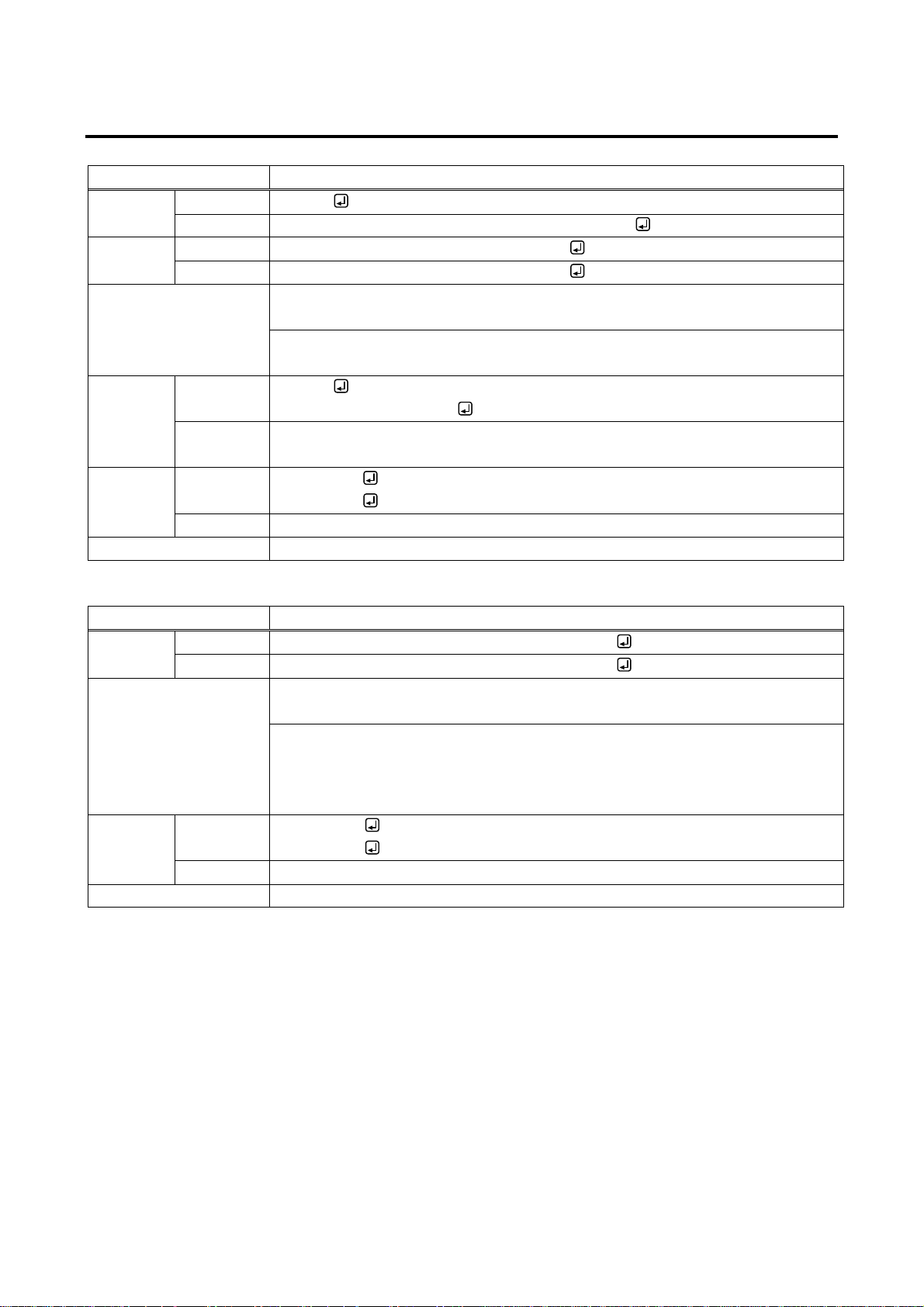
MSD-62 series Command Guide
@GSL / @SSL
Audio out p ut le v e l
Getting
Command
@GSL
Response
@GSL, level_1, level_2, level_3,
, level_8
Command
@SSL, ch_1, level_1 (, ch_2, level_2
)
Response
@SSL, ch_1, level_1 (, ch_2, level_2
)
-60 to 10 [Default] 0
example
Response
@GSL,-4,-4,-4,-4,0,0,0,0
Description
Getting the set audio output level.
Description
Setting OUT1 audi o output lev el to -4 dB.
@SOL
Relative value of audio output level
Setting
Command
@SOL, ch_1, updown_1 (, ch_2, updown_2
)
Response
@SOL, ch_1, updown_1 (, c h_2, updown_2
)
exceeds the limit value (-60 to +10), the limit value will be applied.
example
Response
@SOL,1,-1
Description
Lower 1 dB of audio output lev el of O UT1.
Remarks
If you change the output lev el while muted, it will be unmuted.
3.3.10 Audio
Setting
Parameter level_1-8: Audio output level
ch_1-8: Output channel
0 = All outputs, 1 = OUT1 to 8 = OUT8
Getting
Setting
example
Command
Command
Response
@GSL
OUT1 to OUT4: -4 dB, OUT5 to OUT8: ±0 dB
@SSL,1,-4
@SSL,1,-4
・・・, ・・・
・・・
・・・
Remarks If you change the output lev el while muted, it will be unmuted.
・・・
・・・
Parameter ch_1-8: O utput channel
0 = All outputs, 1 = OUT1 to 8 = OUT8
updown_1-8 : Relat ive value setting
-70 to 70
The specified value is added to the current audio output level. If the total value
Setting
Command
@SOL,1,-1
62
Page 63
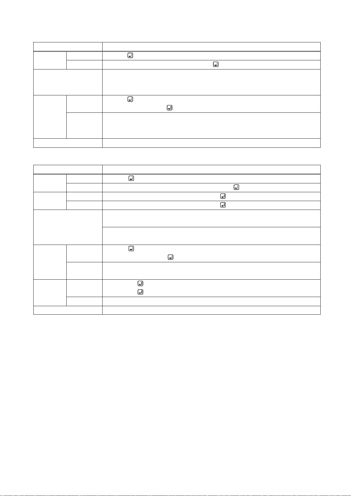
@GOL
Limit status of audi o output leve l
Response
@GOL, out_1, out_2, out _3,
, out_8
1 = maximum settable value (+10 dB)
Getting
Command
@GOL
@GAM / @SAM
Audio out p ut m ute
0 = Mute OFF [Default], 1 = Mute ON
Getting
Command
@GAM
OUT1 to OUT4: M ute ON, OUT5 to OUT8: Mute OFF
Setting
Command
@SAM,1,1
Getting Command @GOL
・・・
Parameter out_1-8: Lim it status of audio output level
-1 = minimum settable value (-60 dB), 0 = not limit status,
MSD-62 series Command Guide
example
Description Getting limit status of audio output level.
Remarks -
Getting Command @GAM
Setting Command @SAM, ch_1, mute_1 (, ch_2, mute_2・・・)
Parameter mute_1-8: Audio output mute
ch_1-8: Output channel
example
Description Getting the set value of audio output mute.
Response
Response @GAM, mute_1, mute_2, mute_3, ・・・, mute_8
Response @SA M, c h_1, mute_1 (, ch_2, mute_2・・・)
Response
@GOL,1,1,1,1,0,0,0,0
OUT1 to OU T4 : maximum settable value
OUT5 to OUT8: not reach the limit value
0 = All outputs, 1 = OUT1 to 8 = OUT8
@GAM,1,1,1,1,0,0,0,0
example
Description Muting OUT1 audio output.
Remarks -
Response
@SAM,1,1
63
Page 64
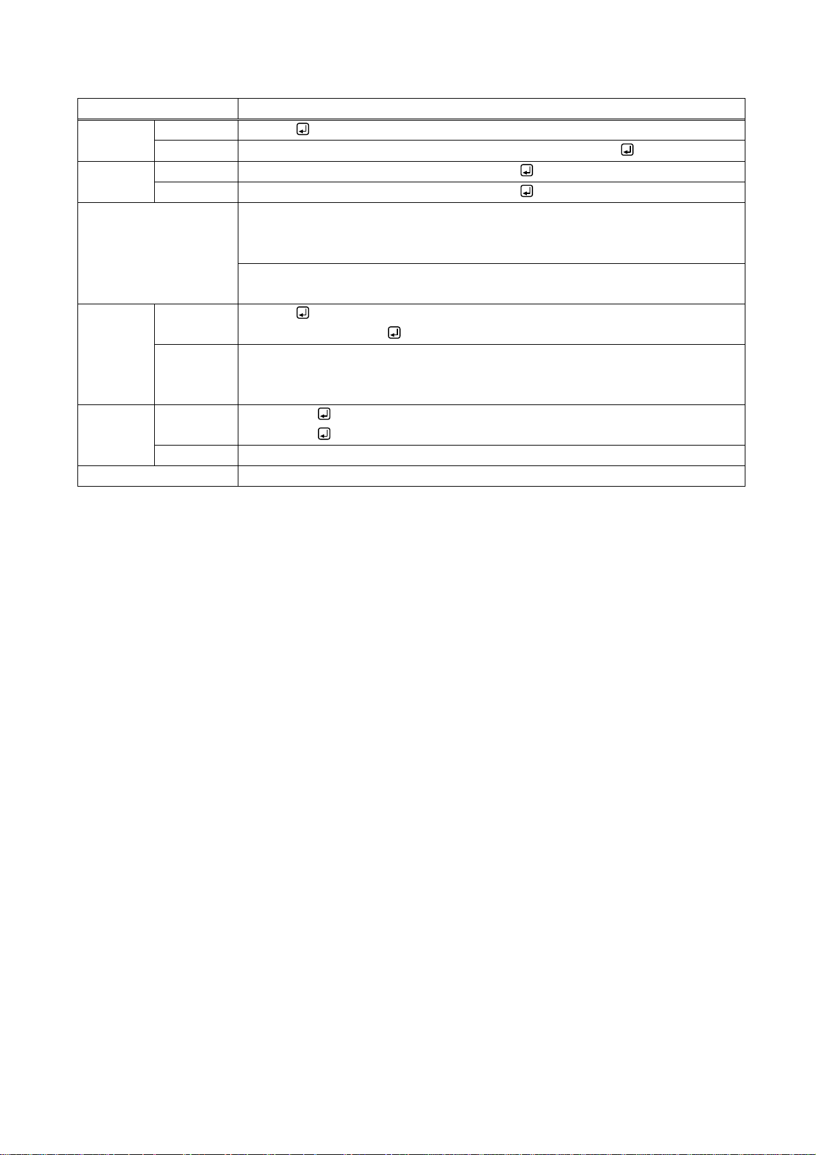
MSD-62 series Command Guide
@GAS / @SAS
Selecting audio input
Response
@GAS, select_1, select_2, select_3, select_4,
, select_8
Response
@SAS, ch_1, select_1 (, c h_2, select_2
)
Parameter
select_1-8: Audio input selec tion
2 = analog audio 2
ch_1-8: Input channel
example
Response
@GAS,1,0,0,0,0,0,0,0
example
Response
@SAS,3,0
Description
Setting IN3 audio input to digital audio.
Remarks
Getting Command @GAS
Setting Command @SAS, ch_1, select_1 (, c h_2, select_2・・・)
・・・
0 = Digital audio [Default], 1 = analog audi o 1,
0 = All d igita l input s, 1 = IN1 to 8 = IN8
Getting
Description Getting the set audio input selecti on.
Setting
Command
Command
@GAS
IN1: analog audio IN1
Other input channels: digital audio
@SAS,3,0
・・・
-
64
Page 65
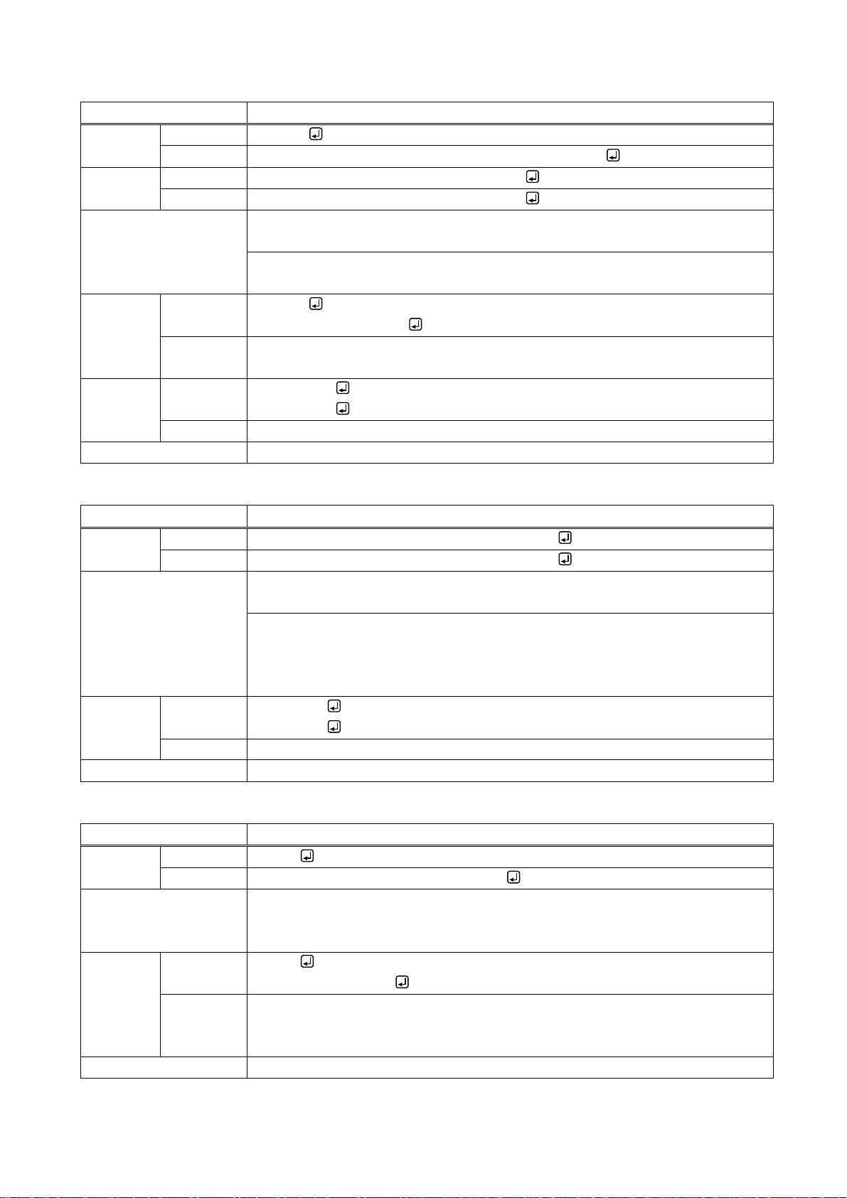
@GSO / @SSO
Aduio input level
Response
@GSO, level_1, level_2, level_3, level_4,
, level_8
Response
@SSO, ch_1, level_1 (, ch_2, level_2
)
Parameter
level_1-8: Audio input level
0 = All inputs, 1 = IN1 to 8 = IN8
Getting
Command
@GSO
IN5: -4 dB, other input channels: ±0 dB
example
Response
@SSO,5,-8
Description
Setting IN5 audio input level to -8 dB .
Remarks
@SIL
Relative value of audio inpu t level
Response
@SIL, ch_1, updown_1 (, ch_2, updown_2
)
exceeds the limit value (-60 to +0), the limit value will be appli ed.
Setting
Command
@SIL,1,-1
@GIL
Limit status of audio input level
example
Response
@GIL,1,0,0,0,0,0,0,0
Getting Command @GSO
Setting Command @SSO, ch_1, level_1 (, ch_2, level_2・・・)
・・・
-60 to 0 [Default] 0
ch_1-8: Input c hannel
MSD-62 series Command Guide
・・・
example
Response
@GSO,0,0,0,0,-4,0,0,0
Description Getting audio input level.
Setting
Command
@SSO,5,-8
-
Setting Command @SIL, ch_1, updown_1 (, ch_2, updown_2・・・)
・・・
Parameter ch_1-8: I nput channel
0 = All inputs, 1 = IN1 to 8 = IN8
updown_1-8: Setting relative value
-60 to 60
The specified value is added to the current audio input level. If the total value
example
Response
@SIL,1,-1
Description Lowering IN1 audio input level (1 dB).
Remarks -
Getting Command @GIL
Response @GIL, in_1, in_2, in_3, in_4, ・・・, in_8
Parameter in_1-8: Limit status
-1 = minimum settable v alue (-60 dB), 0 = not limi t stat us,
1 = maximum settable value (±0 dB)
Getting
Command
@GIL
Description Getting the set limit status of audio input level.
IN1: maximum settable value
Other input channels: not limit value
Remarks -
65
Page 66
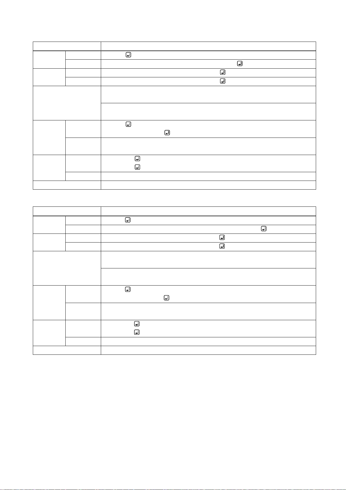
MSD-62 series Command Guide
@GLO / @SLO
Output lip sync
Response
@GLO, frame_1, frame_2, frame_3,
, frame_8
Response
@SLO, ch_1, frame_1 (, c h_2, f r am e_2
)
Parameter
frame_1-8: Output lip sync
0 = All outputs, 1 = OUT1 to 8 = OUT8
Getting
Command
@GLO
OUT1 to OUT4: 0 frame, OUT5 to OUT8: 2 frames
example
Response
@SLO,1,2
Description
Setting the OUT1 lip sync to 2 frames.
Remarks
@GLY / @SLY
Input lip sync
Response
@GLY, frame_1, frame_2, frame_3, frame_4,
, frame_8
Response
@SLY, ch_1, frame_1 (, ch_2, frame_2
)
Parameter
frame_1-8: Input li p sync
0 = All inputs, 1 = IN1 to 8 = IN8
Getting
Command
@GLY
IN4: 2 frames, other input channels: 0 frame
example
Response
@SLY,4,2
Remarks
Getting Command @GLO
・・・
Setting Command @SLO, ch_1, frame_1 (, c h_2, f r am e_2・・・)
・・・
0 to 8 [Default] 0
ch_1-8: Output channel
example
Response
@GLO,0,0,0,0,2,2,2,2
Description Getting the set lip sync of the output side.
Setting
Command
@SLO,1,2
-
Getting Command @GLY
Setting Command @SLY, ch_1, frame_1 (, ch_2, frame_2・・・)
・・・
0 to 8 [Default] 0
ch_1-8: Input c hannel
example
Response
@GLY,0,0,0,2,0,0,0,0
Description Getting the set lip sync of input side.
・・・
Setting
Command
@SLY,4,2
Description Setti ng the IN4 lip sync to 2 frames.
-
66
Page 67
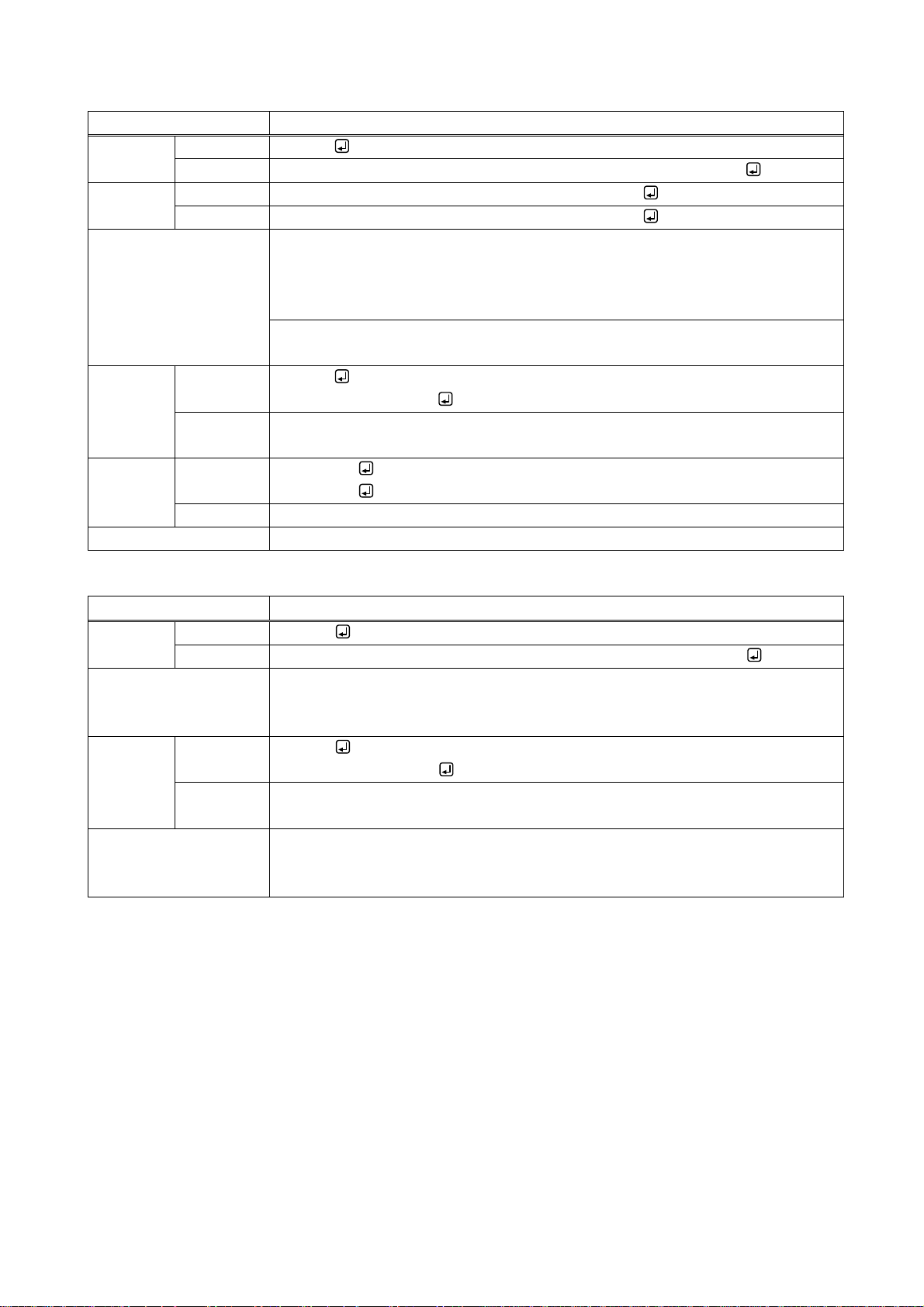
MSD-62 series Command Guide
@GSF / @SSF
Sampling frequen cy
Response
@GSF, frequency_1, frequency_2, frequency_3,
, frequency_8
Response
@SSF, ch_1, frequency_1 (, ch_2, frequency_2
)
Parameter
frequency_1-8: Sampling frequency
0 = All outputs, 1 = OUT1 to 8 = OUT8
Description
Getting sampling frequency settings.
example
Response
@SSF,1,3
Description
Setting OUT1 sampling frequency to 48 kHz.
Remarks
@GFD
Actual sampling frequency
Response
@GFD, frequency_1, frequency_2, frequency_3,
, frequency_8
Parameter
frequency_1-8: Sampling frequency
4 = 88.2 kHz, 5 = 96 kHz, 6 = 192 kHz
Getting
Command
@GFD
OUT1 to OUT4: 96 kHz, OUT5 to OUT8: 48 kHz
Remarks
“@GSF / @SSF Sampling frequency” is set to “AUTO”, the sampli ng frequenc y
Getting Command @GSF
・・・
Setting Command @SSF, ch_1, frequency_1 (, ch_2, frequency_2・・・)
・・・
0 = AUTO [Default], 1 = 32 kHz, 2 = 44.1 kHz,
3 = 48 kHz, 4 = 88.2 kHz, 5 = 96 kHz,
6 =192 kHz
ch_1-8: Output channel
Getting
example
Command
Response
@GSF
@GSF,0,0,0,0,2,2,2,2
OUT1 to OUT4: AUTO, OUT5 to OUT8: 32 kHz
Setting
Command
@SSF,1,3
-
Getting Command @GFD
1 = 32 kHz, 2 = 44.1 kHz, 3 = 48 kHz,
example
Response
@GFD,5,5,5,5,3,3,3,3
Description Getting the actual sampling frequency.
・・・
that is output actually is returned. If it is set to value ot her than “ A UTO ”, the set
sampling frequency is returned.
67
Page 68
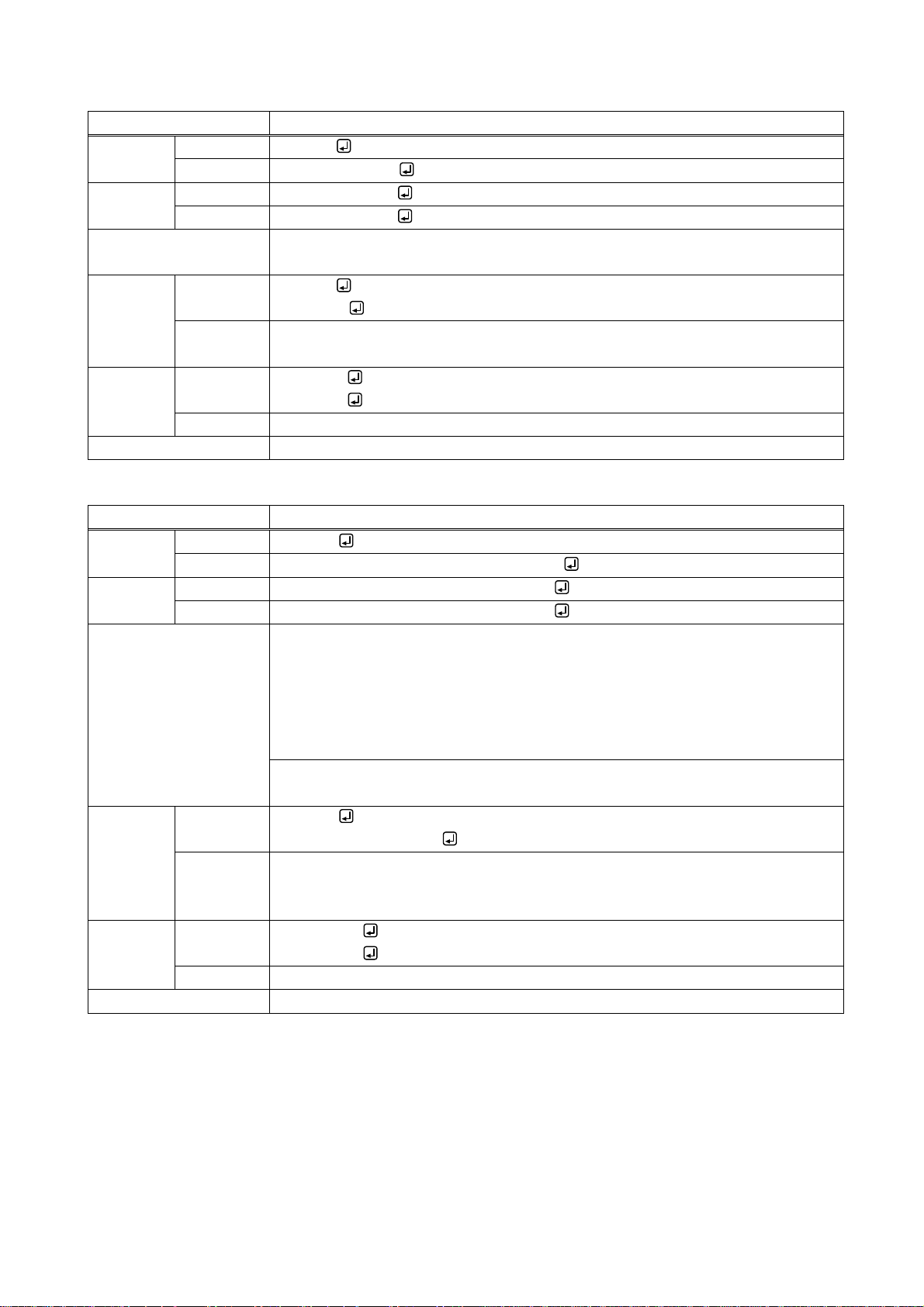
MSD-62 series Command Guide
@GCS / @SCS
Analog audio output
Response
@GCS, channel
Response
@SCS, channel
Parameter
channel: Output channel
example
Response
@GCS,2
Description
Getting the analog audio output setting.
example
Response
@SCS,1
Remarks
@GMD / @SMD
Multi channel audio output
Getting
Command
@GMD
Response
@GMD, out_1, out_2, out_3,
, out_8
Setting
Command
@SMD, ch_1, out_1 (, ch_2, out_2
)
Response
@SMD, ch_1, out_1 (, ch_2, out_2
)
Parameter
out_1-8: Multi channel audi o output
8 = DOWN MIX [Default]
ch_1-8: Output channel
example
Response
@GMD,4,4,4,4,8,8,8,8
example
Response
@SMD,1,8
Description
Setting OUT1 to output downmixed audio.
Remarks
Getting Command @GCS
Setting Command @SCS, channel
1 = OUT1 [Default] to 8 = OUT8
Getting
Command
@GCS
Distributing audio from the OUT2.
Setting
Command
@SCS,1
Description Setting the analog audio output t o OUT 1.
-
・・・
・・・
・・・
0 = CH1 / CH2 STEREO, 1 = CH3 / CH4 STEREO,
2 = CH5 / CH6 STEREO, 3 = CH7 / CH8 STEREO,
4 = CH1 / CH2 MONO, 5 = CH3 / CH4 MONO,
6 = CH5 / CH6 MONO, 7 = CH7 / CH8 MONO,
0 = All outputs, 1 = OUT1 to 8 = OUT8
Getting
Command
@GMD
Description Getting the multi channel audio out put’s setting.
OUT1 to OUT4: Outputs monaural audio of CH1 / CH2
OUT5 to OUT8: Outputs downmixed audio.
Setting
Command
@SMD,1,8
-
68
Page 69
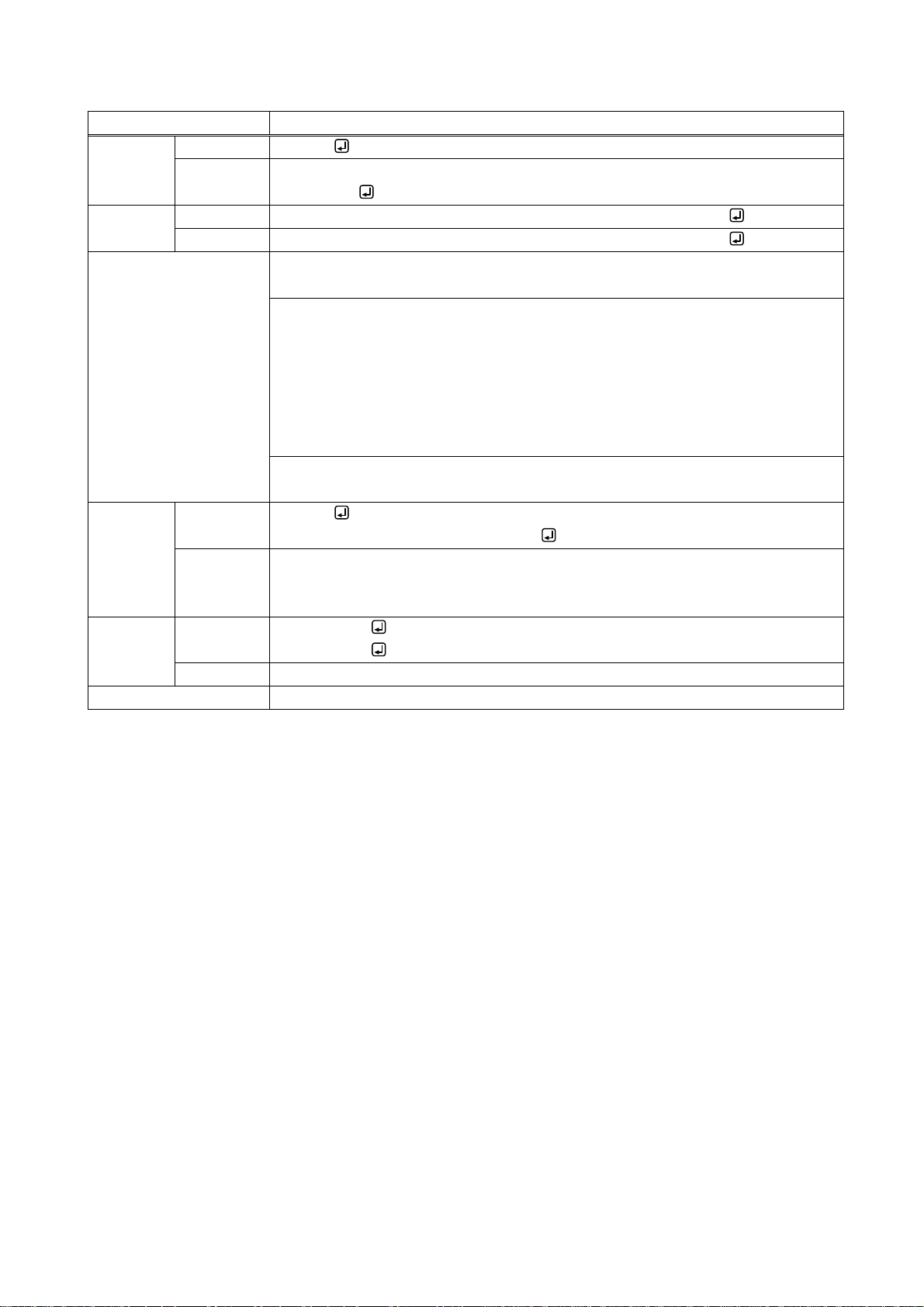
@GAT / @SAT
Test tone
Response
@GAT, tone_1, speaker_1, tone_2, speaker_2, tone_3, speaker_3,
, tone_8,
Command
@SAT, ch_1, tone_1, speaker_1 ( , ch_2, tone_2, speaker_2
)
0 = OFF [Default], 1 = 1 kHz, 2 = 400 Hz
speaker_1-8: Speaker
0 = All outputs, 1 = OUT1 to 8 = OUT8
Getting
Command
@GAT
Setting
Command
@SAT,1,1,0
Getting Command @GAT
speaker_8
Setting
Response @SAT, ch_1, tone_1, speaker_1 (, ch_2, tone_2, speaker_2・・・)
Parameter tone_1-8: Test tone
0 = ALL [Default], 1 = FRONT L/R,
2 = REAR L/R, 3 = REAR L/R CENTER,
4 = FRONT LEFT, 5 = FRONT RIGHT,
6 = LOW FREQUENCY EFFECT, 7 = FRONT CENTER,
8 = REAR LEFT, 9 = REAR RIGHT,
10 = REAR LEFT CENTER, 11 = REAR RIGHT CENTER
ch_1-8: Output channel
MSD-62 series Command Guide
・・・
・・・
example
Description Get ting the set test tone output.
example
Description Setting OUT1 to output test tone (1k Hz) to all speakers.
Remarks -
Response
Response
@GAT,2,1,2,1,2,1,2,1,0,0,0,0,0,0,0,0
OUT1 to OUT4: Outputs test tone (400 Hz) to FRONT L/R.
OUT5 to OUT8: Not output test tone.
@SAT,1,1,0
69
Page 70
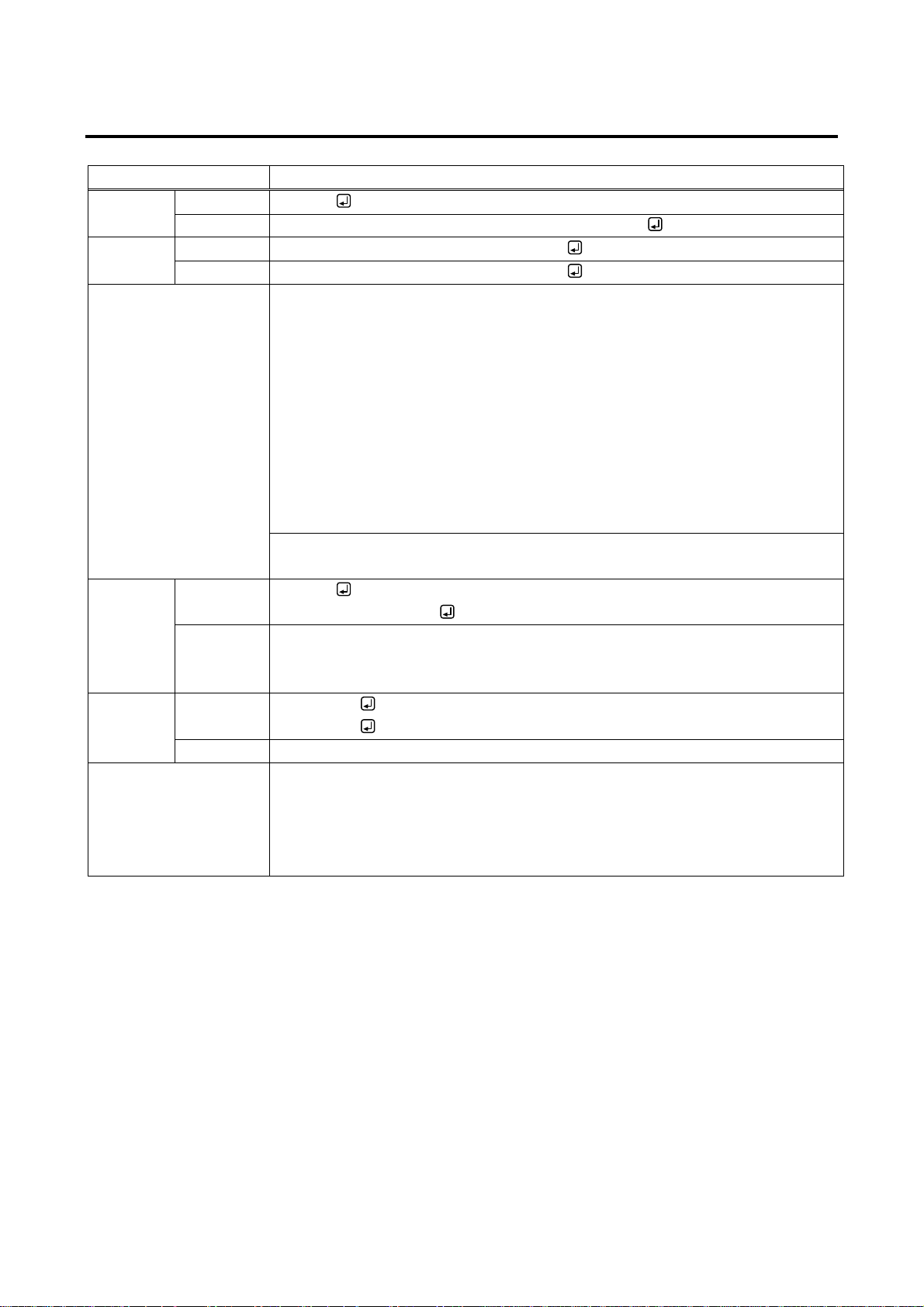
MSD-62 series Command Guide
@GED / @SED
EDID
Getting
Command
@GED
Response
@GED, edid_1, edid_2, edid_3, edid_4,
, edid_8
Command
@SED, ch_1, edid_1 (, ch_2, edid_2
)
Response
@SED, ch_1, edid_1 (, ch_2, edid_2
)
ch_1-8: Input channel
example
Response
@GED,0,0,0,3,0,0,0,0
Description
Getting the set EDID.
other inputs: built-in EDID
Description
Setting IN2: EDID that is read from the sink device connected to OUT 3.
Remarks
These commands are only for digital input.
Signal selection
Copying EDID” in advance.
3.3.11 EDID
Setting
Parameter edid_1-8: EDID
0 = Built-in EDID [Default],
1 = OUT1 MONITOR,
2 = OUT2 MONITOR,
3 = OUT3 MONITOR,
4 = OUT4 MONITOR,
5 = OUT5 MONITOR,
6 = OUT6 MONITOR,
7 = OUT7 MONITOR,
8 = OUT8 MONITOR,
101 to 108 = COPY DATA 1 to COPY DATA 8
・・・
・・・
・・・
0 = All d igita l input s, 1 = IN1 to 8 = IN8
Getting
Setting
example
Command
Command
Response
@GED
IN4: EDID of the sink devic e that is connected to OUT3,
@SED,2,3
@SED,2,3
IN7 and IN8: If “0” (Analog signal) is selected for “@GIN / @SIN
of DVI input connector”, “-1” is acquired and the setting cannot be valid.
In order to use a copied data, read EDI D data f r om the sink device in “@RME
70
Page 71
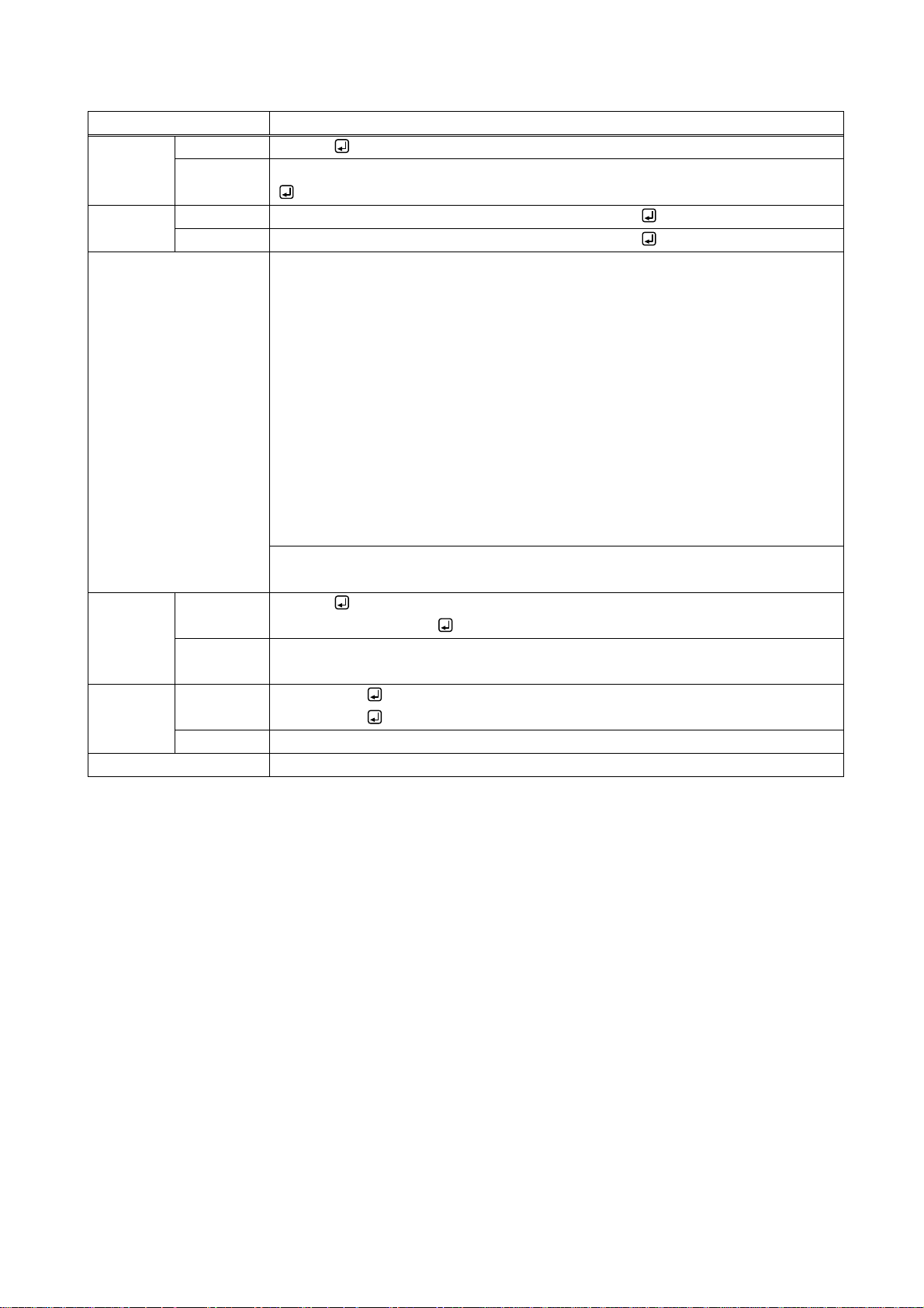
@GVF / @SVF
Input resolution for PC
Response
@GVF, resolution_1, resolution_2, resolution_3, resolution_4,
, resolution_8
Command
@SVF, ch_1, resoluti on_1 ( , ch_2, resolution_2
)
[Default] IN1 to IN8: 1080p(1920x1080)
ch_1-8: Input channel
example
Response
@GVF,6,6,9,6,6,6,6,6
IN3: SXGA+(1400x1050), other input channels: SXGA(1280x1024)
Getting Command @GVF
Setting
Response @SVF, ch_1, resolution_1 ( , ch_2, resolution_2・・・)
Parameter resolution_1-8: Input resolution for PC
0 = SVGA(800x600), 1 = XGA(1024x768),
2 = 720p(1280x720) , 3 = WXGA(1280x768),
4 = WXGA(1280x800), 5 = Quad-VGA(1280x960),
6 = SXGA(1280x1024), 7 = WXGA(1360x768),
8 = WXGA(1366x768), 9 = SXGA+(1400x1050),
10 = WXGA+(1440x900), 11 = WXGA++(1600x900),
12 = UXGA(1600x1200), 13 = WSXGA+(1680x1050),
14 = 1080i(1920x1080) , 15 = 1080p(1920x1080) ,
16 = WUXGA(1920x1200), 17 = QWXGA(2048x1152)
18 = WQHD(2560x1440), 19 = WQXGA(2560x1600),
40 = 2160p@30(3840x2160)
MSD-62 series Command Guide
・・・
・・・
0 = All inputs, 1 = IN1 to 8 = IN8
Getting
Description Getting the set input resolution for PC.
Setting
example
Description S etting EDID of all input channels to UXGA (1600x1200).
Remarks -
Command
Command
Response
@GVF
@SVF,0,12
@SVF,0,12
71
Page 72
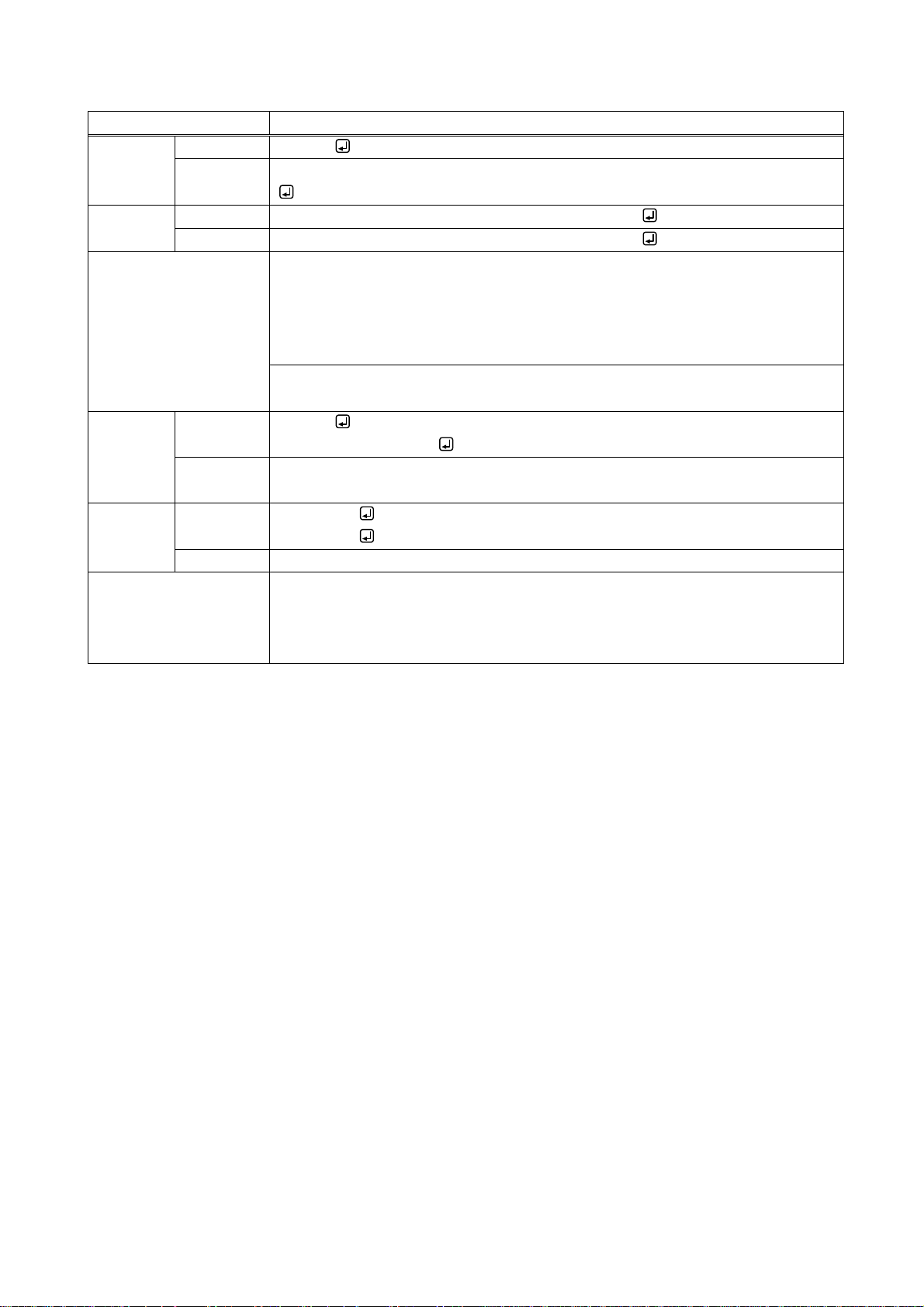
MSD-62 series Command Guide
@GHF / @SHF
Input resolution for AV devices
Response
@GHF, resolution_1, resolution_2, resolution_3, resolution_4,
, resolution_8
Command
@SHF, ch_1, resolution_1 (, ch_2, resolution_2
)
Description
Getting the set input resol ution for AV devices.
example
Response
@SHF,0,4
Description
Setting EDIDs of all input channels to 1080p.
Getting Command @GHF
Setting
Response @SHF, ch_1, resolution_1 (, ch_2, resoluti on_2・・・)
Parameter resolution_1-8: Input resolut ion for AV devices
0 = UNUSED, 1 = 480p,
2 = 720p, 3 = 1080i,
4 = 1080p, 5 = AUTO [Default],
6 = 2160@30, 9 = 4096x2160@30
ch_1-8: Input c hannel
0 = All d igita l input s, 1 = IN1 to 8 = IN8
Getting
example
Setting
Command
Response
Command
@GHF
@GHF,5,5,5,4,5,5,5,5
IN4: 1080p, other inputs: AUTO
@SHF,0,4
・・・
・・・
Remarks These commands are only for digital input.
IN7 and IN8 are available only when “1” (Di gital signal) is selected for “@GIN /
@SIN Signal selection of DVI input connector”. If “0” (Analog signal) is
selected, “-1” is returned.
72
Page 73
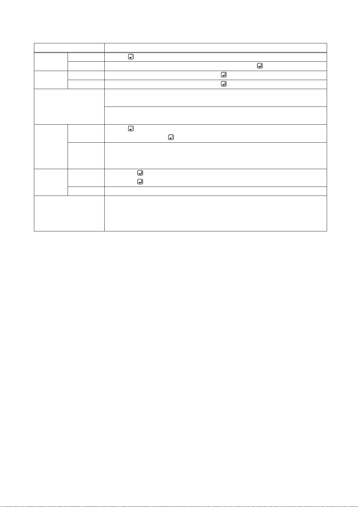
@GDI / @SDI
Deep Color input
Response
@GDI, color_1, color_2, color_3, color_4,
, color_8
Response
@SDI, ch_1, color _1 (, ch_2, c olor _2
)
Parameter
color_1-8: Color depth
0 = All d igita l input s, 1 = IN1 to 8 = IN8
Getting
Command
@GDI
Other input channels: 30-BIT COLOR
Setting
Command
@SDI,4,0
selected, “-1” is returned.
Getting Command @GDI
Setting Command @SDI, ch_1, color _1 (, ch_2, c olor _2・・・)
・・・
0 = 24-BIT COLOR [Default], 1 = 30-BIT COLOR
ch_1-8: Input c hannel
MSD-62 series Command Guide
・・・
example
Description Getting the set color depth.
example
Description Setti ng the set IN4 color depth to 24-BIT COLOR.
Remarks These commands are only for digital input.
Response
Response
@GDI,1,1,1,0,1,1,1,1
IN4: 24-BIT COLOR,
@SDI,4,0
IN7 and IN8 are available only when “1” (Digital si gnal) is selected for “@GIN /
@SIN Signal selection of DVI input connector
”. If “0” (Analog signal) is
73
Page 74
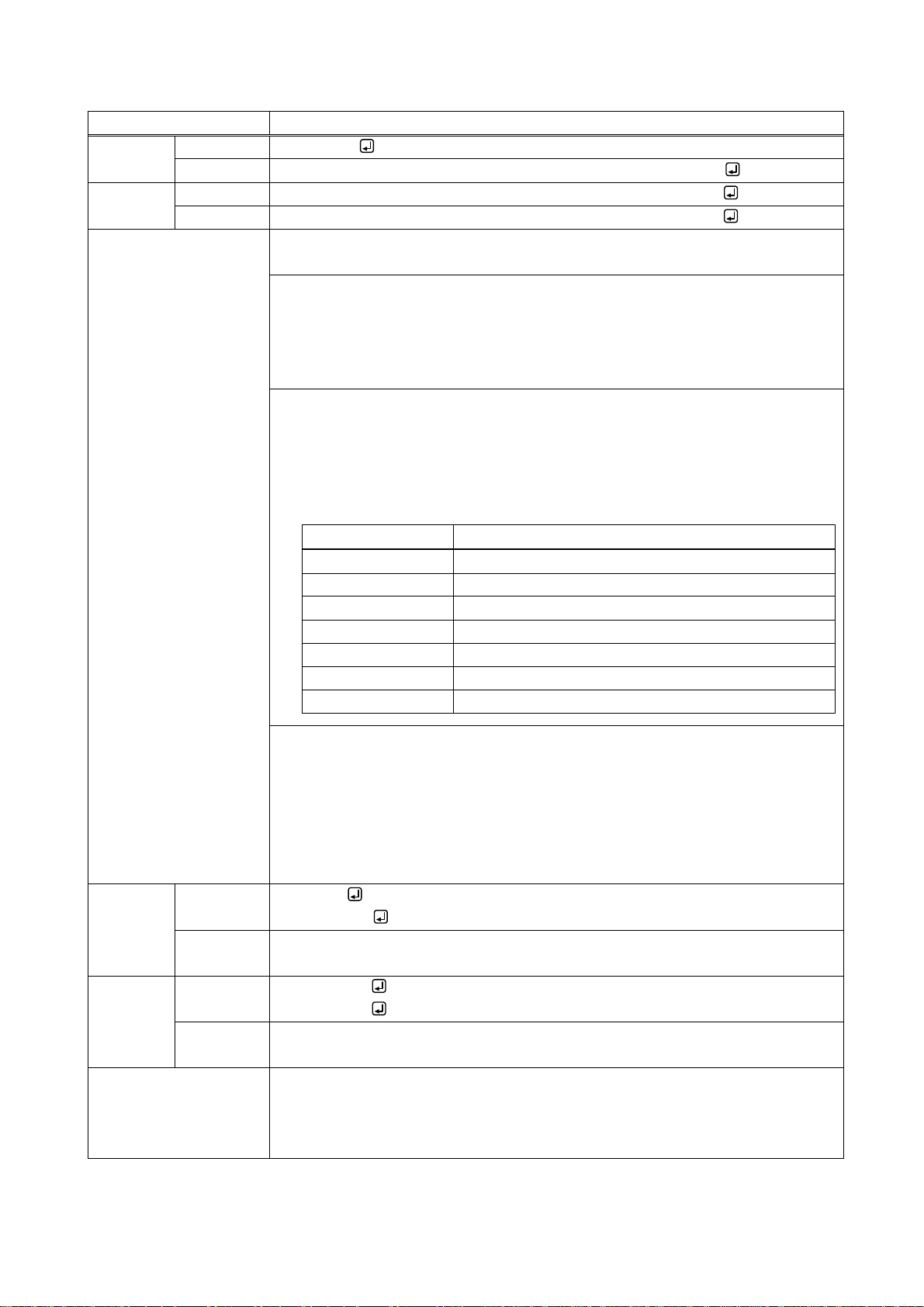
MSD-62 series Command Guide
@GAF / @SAF
Audio form a t
Response
@GAF, ch, format_1, frequency_1 (, format_2, frequency_2
)
Response
@SAF, ch, format_1, frequency_1 (, format_2, frequency_2
)
Parameter
ch: Input channel
DTS
Output disabled / 32 / 44.1 / 48 / 96
Dolby TrueHD
Output disabled / 44.1 / 48 / 88.2 / 96 / 176.4 / 192
sampling frequency.
Getting
Command
@GAF,1
Up to 192 kHz of PCM.
example
Response
@SAF,2,4,3
selected, “-1” is returned.
Getting Command @ GAF, ch
・・・
Setting Command @SAF, ch, format_1, frequency_1 (, format_2, frequency_2・・・)
・・・
0 = All d igita l input s (for setting only), 1 = IN1 to 8 = IN8
format_1-8: Audio format
0 = PCM, 1 = Dol by Digital, 2 = AAC,
3 = Dolby Digital+, 4 = DTS, 5 = DTS-HD,
6 = Dolby TrueHD
[Default] only PCM can be output
frequency_1-8: M aximum sampling frequency
0 = Not output, 1 = 32 kHz, 2 = 44.1 kHz, 3 = 48 kHz,
4 = 88.2 kHz, 5 = 96 kHz, 6 = 176.4 kHz, 7 = 192 kHz
[Default] DTS-HD: 192 kHz, Dolby TrueHD: 96 kHz, other formats:48 kHz
Maximum settabl e sampling frequency depends on the audio f ormat.
Audio format Maximum sampling frequency ( k Hz)
PCM 32 / 44.1 / 48 / 88.2 / 96 / 176.4 / 192
Dolby Digital Output disabled / 32 / 44.1 / 48
AAC Output disabled / 32 / 44.1 / 48 / 88.2 / 96
Dolby Digital+ Out put disabled / 32 / 44.1 / 48
DTS-HD Output disabled / 44. 1 / 4 8 / 88. 2 / 96 / 176.4 / 192
Getting commands: the set audio formats and maximum sampling frequency is
returned.
Setting commands: send the desi r ed audio formats and the maximum s ampling
frequencies. O ther audio formats is set to “0” (Output disabled) for the maximum
sampling frequency. You do not need to specify “0” parameter normally.
PCM is always enabled, you can skip this menu unless you need to change the
example
Response
@GAF,1,0,7
Description Getting the set audio formats for IN1.
Setting
Command
@SAF,2,4,3
Description E nabling IN2 to output PCM and DTS up to 48 kHz (PCM’s sampling frequency is
not changed).
Remarks These commands are only for digital input.
IN7 and IN8 are available only when “1” (Di gital signal) is selected for “@GIN /
@SIN Signal selection of DVI input connector
”. If “0” (Analog signal) is
74
Page 75
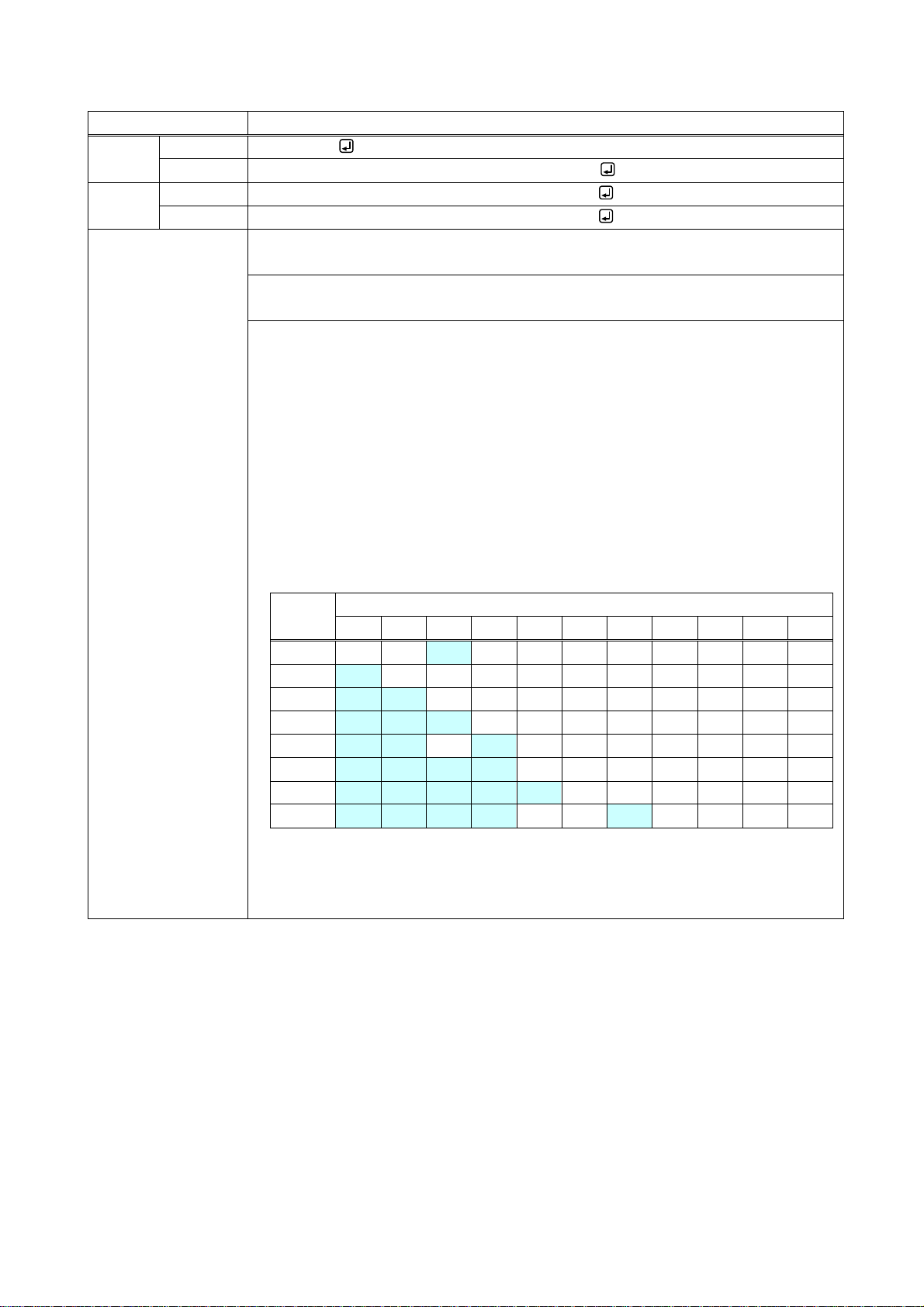
@GSP / @SSP
The number of speakers
Response
@GSP, ch, number, speaker_1 (, speaker_2
)
Response
@SSP, ch, number (, speaker_1, speaker_2
)
Parameter
ch: Input channel
1 to 8 [Default] 2
speaker_1-8: Speaker configuration
0 1 2 3 4 5 6 7 8 9 10
1
Getting Command @GSP, ch
・・・
Setting Command @SSP, ch, number (, speaker_1, speaker_2・・・)
・・・
0 = All d igita l input s (for setting only), 1 = IN1 to 8 = IN8
number: The number of speakers
0 = Front Left / Right [Default], 1 = Low Frequency Effect,
2 = Front Center, 3 = Rear Left / Right,
4 = Rear Center, 5 = Front Left / Right Center,
6 = Rear Left / Right Center, 7 = Front Left / Right Wide,
8 = Front Left / Right Hi gh, 9 = Top Center,
10 = Front Center High
Getting commands: the num ber of speakers and whic h speakers will be used is
returned.
Setting commands: if you do not specify the speaker confi gur ation, the following
configurati on will be applied depending on the set number of speakers.
number
speaker
MSD-62 series Command Guide
OFF OFF ON OFF OFF OFF OFF OFF OFF OFF OFF
ON OFF OFF OFF OFF OFF OFF OFF OFF OFF OFF
2
ON ON OFF OFF OFF OFF OFF OFF OFF OFF OFF
3
ON ON ON OFF OFF OFF OFF OFF OFF OFF OFF
4
ON ON OFF ON OFF OFF OFF OFF OFF OFF OFF
5
ON ON ON ON OFF OFF OFF OFF OFF OFF OFF
6
ON ON ON ON ON OFF OFF OFF OFF OFF OFF
7
ON ON ON ON OFF OFF ON OFF OFF OFF OFF
8
For speaker confi gur ations: the number and total number of speakers (speaker_1-8)
do not match, the number is set automatically based on the setting of speaker_1-8.
In case the number exceeds the settable range, an error is retur ned.
75
Page 76
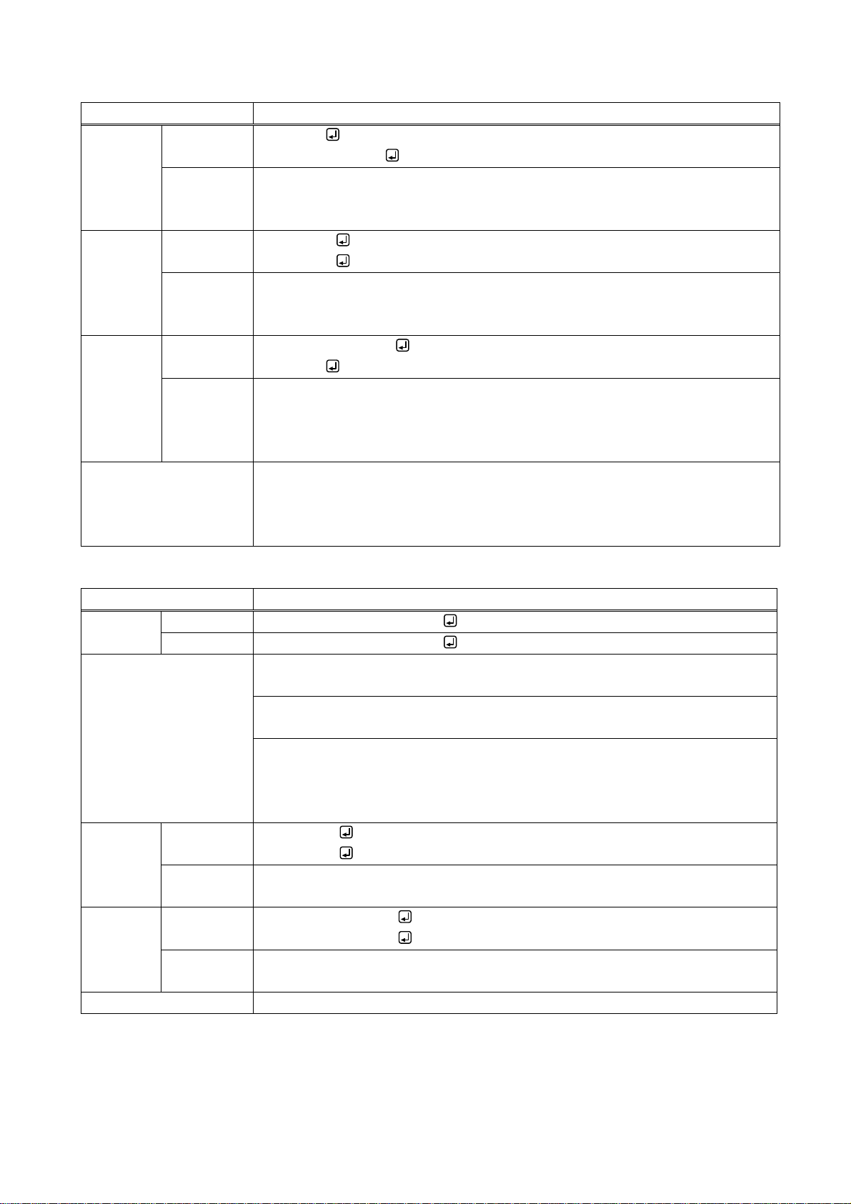
MSD-62 series Command Guide
@GSP / @SSP
The number of speakers (cont’d)
example
Response
@GSP,1,6,0,1,2,3
example
Response
@SSP,2,8
Description
Setting IN2 speaker configuration to Front Left / Right , Low Frequency Ef fect,
Completed normally .
Setting
Command
@SSP,3,8,0,3,5,6,7
Description
Setting IN3 speaker configuration to Front Left / Right , Rear Left / Right , F r ont
selected, “-1” is returned.
@RME
Copying EDID
Setting
Command
@RME, out, number, nam e
Response
@RME, out, number, nam e
Parameter
out: Connector to be loaded
1 to 8
name: COPY DATA name
changing current ly saved name.
Setting
Command
@RME,1,1
DATA 1.
Setting
Command
@RME,3,4,800x600
and saving it in COPY DATA 4.
@GED / @SED EDID
Getting
Command
@GSP,1
Description Get ting the IN1 speaker configur ation.
Six speakers (Front Left / Right, Low Frequency Eff ect, Front Center, Rear Left /
Right) are used.
Setting
Command
@SSP,2,8
Front Center, Rear Left / Right , Rear Left / Right Center (eight speakers).
example
Response
@ERR,1
Left / Right Center, Rear Left / Right Center, Front Left / Right Wi de.
The number of speakers is 10 which exceeds the settable value, and it causes
the error.
Remarks These commands are only for digital input.
IN6 and IN7 are available only when “1” (Digital signal) is selected for “@GIN /
@SIN Signal selection of DVI input connector
”. If “0” (Analog signal) is
1 = OUT1 to 8 = OUT8
number: Destinati on COPY DATA number
Up to 10 characters using 20 t o 7D from ASCII codes.
You can skip this setti ng. I n this case, only EDID settings are saved without
example
Response
@RME,1,1
Description Loading EDID dat a of t he sink devic e c onnec ted to OUT1 and saving it in COPY
example
Response
@RME,3,4,800x600
Description Loading EDID dat a of t he sink devic e c onnec ted to OUT3, naming it “800x600”
Remarks
76
Page 77
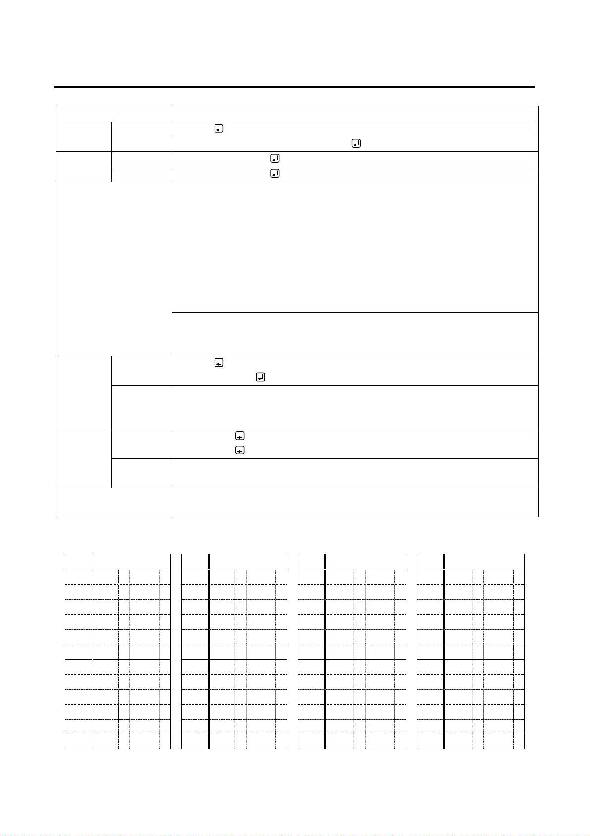
3.3.12 RS-232C communication
@GCT / @SCT
RS-232C communication
Getting
Command
@GCT
Response
@GCT, setting_1, setting_2, setting_3
Command
@SCT, port, setting
Response
@SCT, port, setting
[Table 3.1]
2 = IN5 to IN6 3 = OUT1 to OUT8
Getting
Command
@GCT
example
Response
@SCT,1,24
Description
Setting RS-232C as foll ows: baud rate = 19200 [bps], data bit length = 8 [bit],
parity check = NONE, stop bi t = 1 [bit] .
Remarks
If IP address or RS-232C comm unic ation setting is changed, the comm unic ation
Setting
Parameter setting : Communic ation setting
setting_1 : Communication setting of RS-232C connector
setting_2 : Communication setting of HDBaseT input connector I N5 and IN6
setting_3 : Communication setting of HDBaseT output connector OUT1 to OUT8
・Baud rate (4800, 9600, 19200, 38400 [bps] [Default] 9600)
・Data length (8, 7 [bit] [Default] 8)
・Parity check (NONE, EVEN, O DD [Default] NONE)
・Stop bit (1, 2 [bit] [Default] 1)
For setting val ues, see the
port: RS -232C c hannel
0 = All channels, 1 = RS-232C connector,
MSD-62 series Command Guide
.
example
Response
@GCT,24,24,24
Description Getting communication settings of RS-232Cs.
All baud rates = 19200 [bps], data bit length = 8 [bit], parit y check = NONE,
stop bit =1 [bit]
Setting
Command
@SCT,1,24
may be disabled. Change the environmental setti ngs based on the MSD settings.
[Table 3.1] Parameter of RS-232C communi cat io n setting s
Value Communication Value Communication Value Communication Value Communication
0 4800 8 NONE 1 12 9600 8 NONE 1 24 19200 8 NONE 1 36 38400 8 NONE 1
1 4800 8 NONE 2 13 9600 8 NONE 2 25 19200 8 NONE 2 37 38400 8 NONE 2
2 4800 8 ODD 1 14 9600 8 ODD 1 26 19200 8 ODD 1 38 38400 8 ODD 1
3 4800 8 ODD 2 15 9600 8 ODD 2 27 19200 8 ODD 2 39 38400 8 ODD 2
4 4800 8 EVEN 1 16 9600 8 EVEN 1 28 19200 8 EVEN 1 40 38400 8 EVEN 1
5 4800 8 EVEN 2 17 9600 8 EVEN 2 29 19200 8 EVEN 2 41 38400 8 EVEN 2
6 4800 7 NONE 1 18 9600 7 NONE 1 30 19200 7 NONE 1 42 38400 7 NONE 1
7 4800 7 NONE 2 19 9600 7 NONE 2 31 19200 7 NONE 2 43 38400 7 NONE 2
8 4800 7 ODD 1 20 9600 7 ODD 1 32 19200 7 ODD 1 44 38400 7 ODD 1
9 4800 7 ODD 2 21 9600 7 ODD 2 33 19200 7 ODD 2 45 38400 7 ODD 2
10 4800 7 EVEN 1 22 9600 7 EVEN 1 34 19200 7 EVEN 1 46 38400 7 EVEN 1
11 4800 7 EVEN 2 23 9600 7 EVEN 2 35 19200 7 EVEN 2 47 38400 7 EVEN 2
77
Page 78
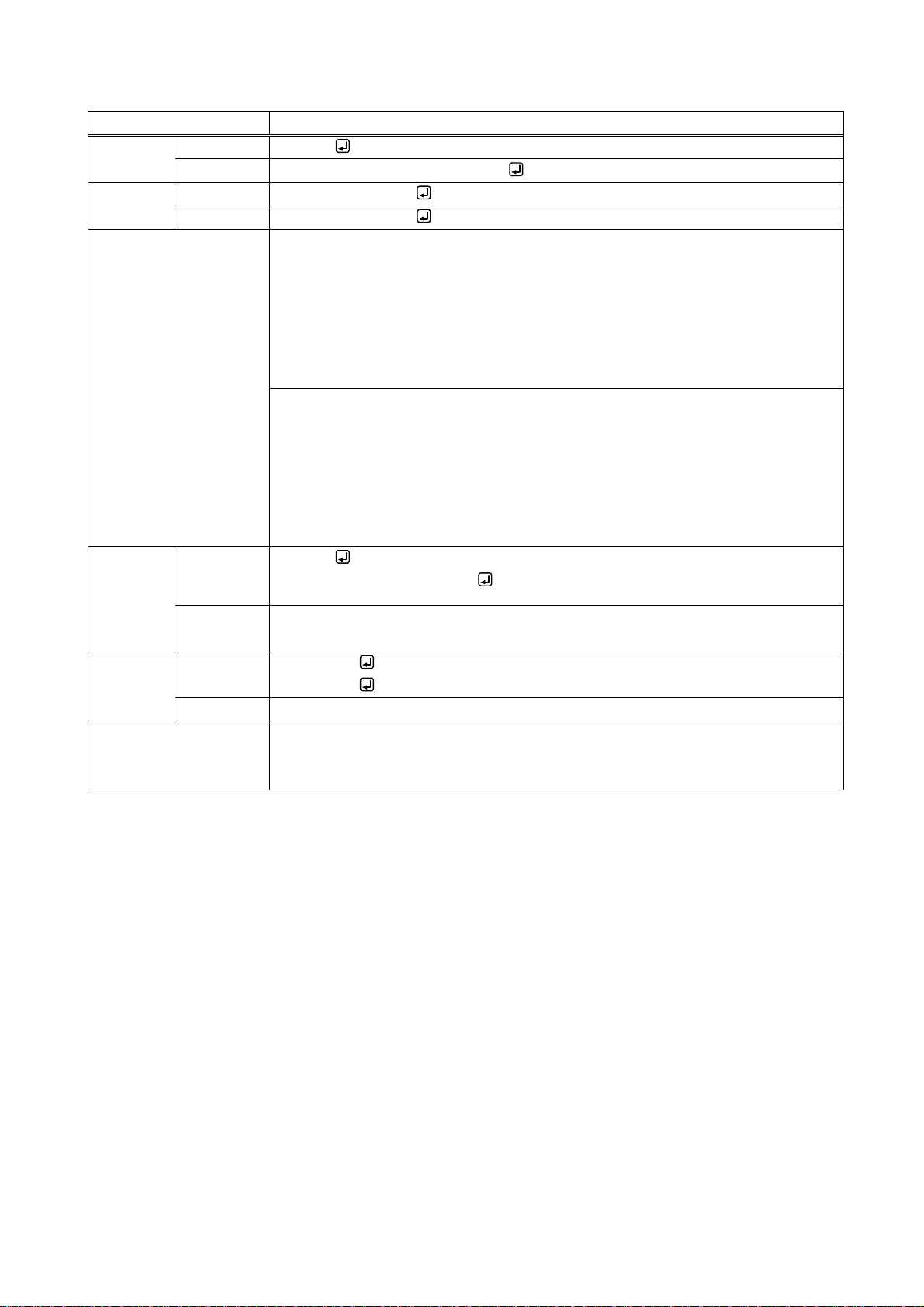
MSD-62 series Command Guide
@GCF / @SCF
RS-232C communication mode
Response
@GCF, mode_1, …, mode_11
Response
@SCF, port, mode
Parameter
mode: Operation mode
0 = RECEIVER mode [Default], 1 = TRANSMITTER mode
Description
Getting the set operation mode
example
Response
@SCF,1,1
Description
Setting RS-232C connector to TRANSMITTER mode.
Remarks
These commands are only for RS-232C.
may be disabled. Change the environmental settings based on the MSD settings.
Getting Command @GCF
Setting Command @SCF, port, mode
mode_1: Operation mode of RS-232C connector
mode_2: Operation mode of HDBaseT input connector IN5
mode_3: Operation mode of HDBaseT input connector IN6
mode_4 to mode_11:Operation mode of HDBaseT output connector OUT1 to
port: RS -232C c hannel
0 = All channels, 1 = RS-232C connector,
2 = IN5, 3 = IN6,
4 = OUT1, 5 = OUT2,
6 = OUT3, 7 = OUT4,
8 = OUT5, 9 = OUT6,
10 = OUT7, 11 = OUT8
Getting
example
Command
Response
@GCF
@GCF,1,1,1,1,1,1,1,1,1,1,1
OUT8
TRANSMITTER mode
Setting
Command
@SCF,1,1
If IP address or RS-232C comm unic ation setting is changed, the comm unic ation
78
Page 79
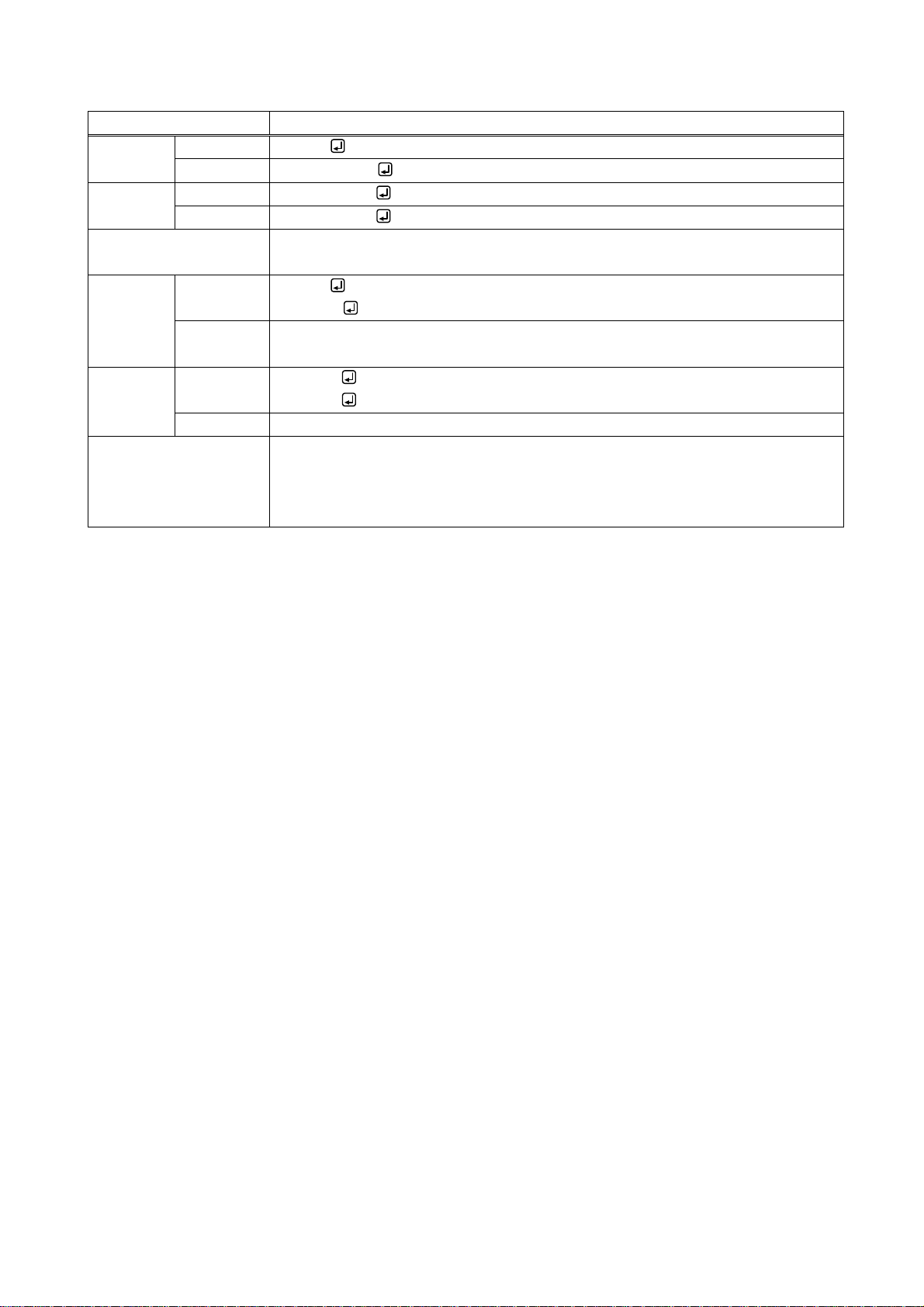
MSD-62 series Command Guide
@GCI / @SCI
RS-232C transmission
Response
@GCI, mode
Response
@SCI, mode
Parameter
mode: RS-232C transmission mode
Response
@GCI,0
Description
Getting the set RS-232C transmission mode.
example
Response
@SCI,1
the RS-232C transmission sett ing to OFF can be accepted.
Getting Command @GCI
Setting Command @SCI, mode
0 = RS-232C transmission mode OFF, 1 = RS-232C transmission mode ON
Getting
example
Setting
Description Setti ng the RS-232C transmission mode to ON.
Remarks Once RS-232C transmission mode is set to ON, the RS-232C connector cannot
Command
Command
@GCI
Setting the RS-232C transmission mode to OFF.
@SCI,1
be used for communication command control from PC to the MSD or for cont r ol
command output from the MS D to external devices. Only the command that sets
79
Page 80
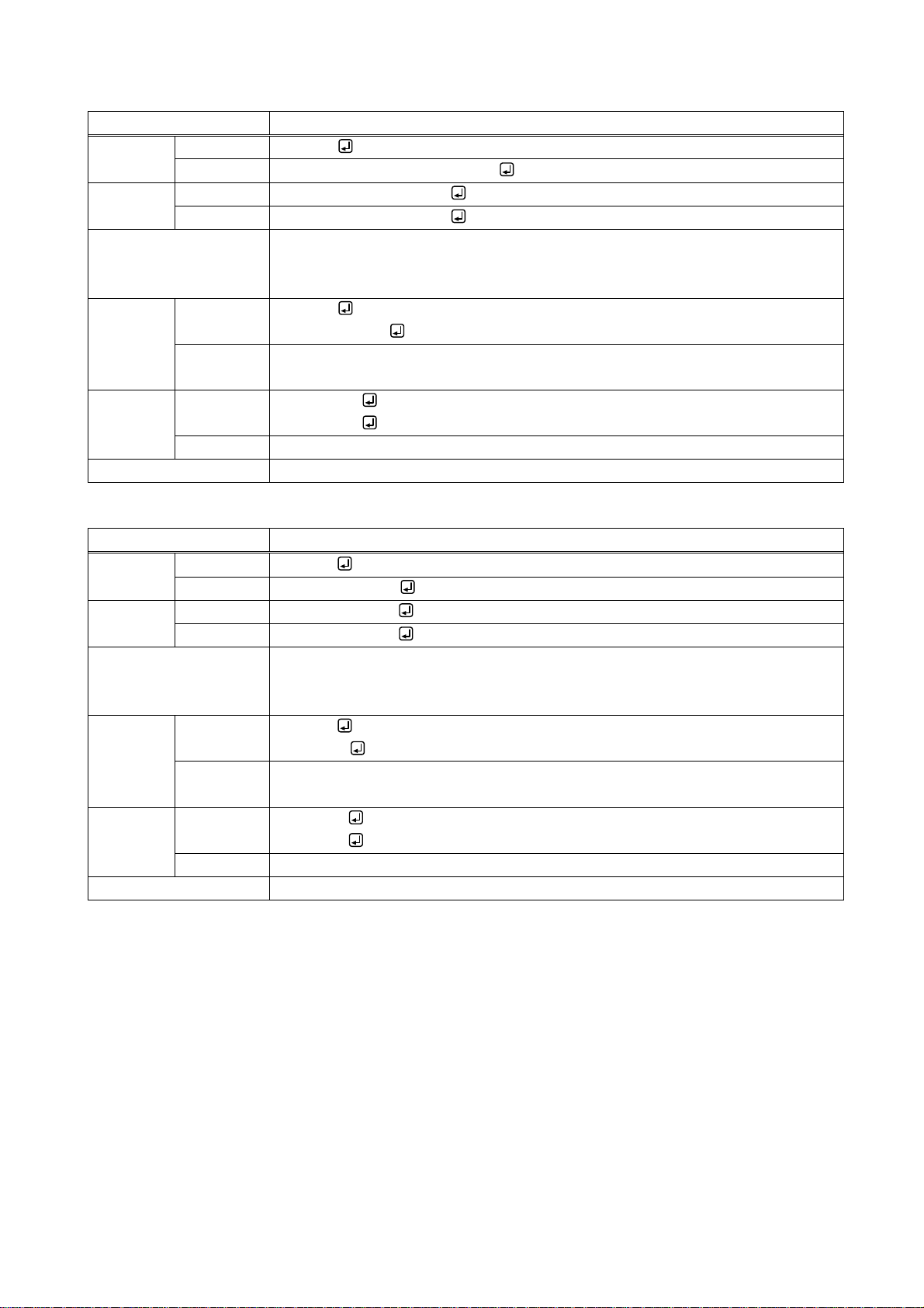
MSD-62 series Command Guide
@GCQ / @SCQ
RS-232C HDBaseT sending channel
Response
@GCQ, ch_1 (,ch_2,…,ch_10)
Response
@SCQ, ch_1 (,ch_2,…)
Parameter
ch_1-10: RS-232C HDBaseT sending channel
105 = IN5B to 106 = IN6B
Getting
Command
@GCQ
Setting the OUT1B to OUT4B to RS-232C HDBaseT sending channel .
example
Response
@SCQ,1,8
Description
Setting the OUT1B and OUT8B to RS-232C HDBaseT sending channel.
Remarks
@GCR / @SCR
RS-232C HDBaseT receiving channel
Command
@SCR, channel
105 = IN5B to 106 = IN6B
Getting
Command
@GCR
Setting the OUT4B to RS-232C HDBaseT receiving channel setting.
Remarks
Only one channel can be set for receiving channel.
Getting Command @GCQ
Setting Command @SCQ, ch_1 (,ch_2,…)
0 = All OUTB channels, 1 = OUT1B to 8 = OUT8B,
example
Description Getting the set RS-232C HDBaseT sending channel.
Setting
Getting Command @GCR
Setting
Parameter channel: RS-232C HDBaseT receiving channel
example
Description Getting the set RS-232C HDBaseT receiving channel setting.
Response
Command
Response @GCR, channel
Response @SCR, channel
Response
@GCQ,1,2,3,4
@SCQ,1,8
-
1 = OUT1B to 8 = OUT8B,
@GCR,4
Setting
example
Description Setting the OUT1B to RS-232C HDBaseT receiving c hannel setting.
80
Command
Response
@SCR,1
@SCR,1
Page 81
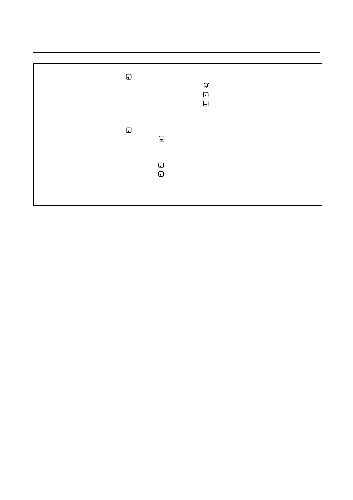
MSD-62 series Command Guide
@GIP / @SIP
IP address
Getting
Command
@GIP
Response
@GIP, unit_1, unit _2, unit_3, unit_4
Command
@SIP, unit_1, unit_2, unit_3, unit_4
Response
@SIP, unit_1, unit_2, unit_3, unit_4
0 to 255 = 8 bit (Decimal notati on) [Default]192.168.1.199
IP address: 192.168.3.2
Setting
Command
@SIP,192,168,3,2
may be disabled. Change the environmental settings based on the MSD settings.
3.3.13 LAN communication
Setting
Parameter unit_1 : Upper bit of the IP addr ess to unit to unit_4 : lower bit of the IP address
Getting
example
Description Getting the IP address of the MSD.
example
Description Setti ng IP address to 192.168.3.2.
Remarks If IP address or RS-232C comm unic ation setting is changed, the comm unic ation
Command
Response
Response
@GIP
@GIP,192,168,3,2
@SIP,192,168,3,2
81
Page 82
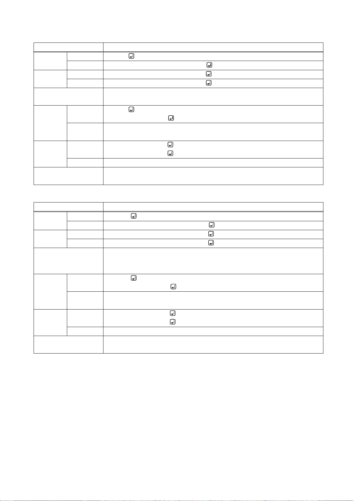
MSD-62 series Command Guide
@GSB / @SSB
Subnet mask
Response
@GSB, unit_1, unit_2, unit_3, unit_4
Response
@SSB, unit_1, unit_2, unit_3, unit_4
Parameter
unit_1 : Upper bit of the subnet mask to unit_4: lower bit of the subnet mask
example
Response
@GSB,255,255,192,0
Description
Getting the set subnet m ask of the MS D.
example
Response
@SSB,255,255,192,0
may be disabled. Change the environmental settings based on the MSD settings.
@GGW / @SGW
Gateway address
Command
@SGW, unit_1, unit _2, unit _3, unit_4
0 to 255 = 8 bit (Decimal notation) [Default]192.168.1.200
Getting
Command
@GGW
Gateway address: 192.168.1.254
Remarks
If IP address or RS-232C comm unic ation setting is changed, the comm unic ation
Getting Command @GSB
Setting Command @SSB, unit_1, unit_2, unit_3, unit_4
0 to 255 = 8 bit (Decimal notati on) [Default] 255.255.255.0
Getting
Setting
Description Setti ng subnet mask to 255.255.192.0 ( = 18 bit).
Remarks If IP address or RS-232C comm unic ation setting is changed, the comm unic ation
Command
Command
@GSB
Subnet mask: 255.255.192.0 ( = 18 bit)
@SSB,255,255,192,0
Getting Command @GGW
Response @GGW, unit_1, unit_2, unit_3, unit_4
Setting
Response @SGW , unit _1, unit_2, unit_3, unit_4
Parameter unit_1: Upper bit of the gateway address to unit_4: l ower bi t of the gat eway
address
example
Description Getting the set gateway address.
Setting
example
Description Setti ng gateway address to 192.168.1.254.
Response
Command
Response
@GGW,192,168,1,254
@SGW,192,168,1,254
@SGW,192,168,1,254
may be disabled. Change the environmental setti ngs based on the MSD settings.
82
Page 83
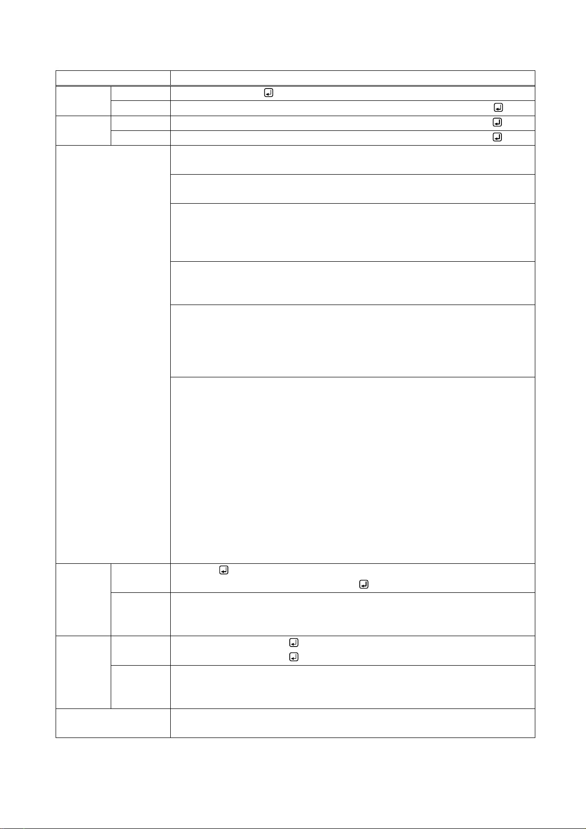
MSD-62 series Command Guide
@GLF / @SLF
LAN communication mode
Response
@GLF, connection, mode (, ip_1, ip_2, ip_3, ip_4, pjlink, tcp, password)
Response
@SLF, connection, mode ( , ip_1, ip_2, ip_3, ip_4, pjlink, tcp, password)
Parameter
connection: Connec tion number
0 = RECEIVER mode [Default], 1 = TRANSMITTER mode
ip_1: Upper bit of the destination IP address to ip_4: lower bit of the destination IP
pjlink: PJLink protocol connection
Available only if t he mode is TRANSMITTER.
tcp: Destination port number
If “pjlink” is set to “1” (PJLink used), “tc p” is “4352” fixed.
authentication for PJLink protocol connection.
example
Response
@SLF,3,1,192,168,1,2,1
may be disabled. Change the environmental settings based on the MSD settings.
Getting Command @GLF, connect ion
Setting Command @S LF, c onnec tion, mode (, ip_1, ip_2, ip_3, ip_4, pjlink, tcp, password)
1 = connection 1 to 8 = connecti on8
mode: Operation mode
address
0 to 255 = 8 bit (Decimal notation) [Default] 192.168.1.198
Available only if t he mode is TRANSMITTER.
0 = PJLink not used [Default], 1 = PJLink used
1 to 65535 [Default] 1100
Available only if t he mode is TRANSMITTER and “pjlink” is set to “0” (PJLink not
used).
password: Password of PJLink protocol
Up to 32 characters of the following ASCII codes: 20, 30 to 39, 41 to 5A, 61 to
7A (alphanumeric characters). [Default] All: 20 (space)
Replied/S et only if t he mode is “1” (TRANSMITTER) and pjlink is “0” (PJLink
not used).
Getting commands: replied only if the password is set.
Setting commands: y ou c an skip this password setting if you disable password
authentication for PJLink protocol connection.
Available only if t he mode is TRANSMITTER and “pjlink” is set to “0” (PJLink not
used).
Getting commands: ret ur ned only if the password is set.
Setting commands: you can skip this password setting if you do not use password
Getting
example
Description Get ting mode settings of connection 3.
Setting
Command
Response
Command
@GLF,3
@GLF,3,1,192,168,1,2,1,PROJECTOR1
Mode = TRANSMITTER mode, destination IP address = 192.168. 1.2,
PJLink = to be used, password = “P ROJE CTO R1”
@SLF,3,1,192,168,1,2,1
Description Setting connection 3 as follows:
Mode = TRANSMITTER mode, destination IP address = 192.168. 1.2,
PJLink = to be used, password = disabling password authentication.
Remarks If IP address or RS-232C communicati on setting is changed, the communication
83
Page 84
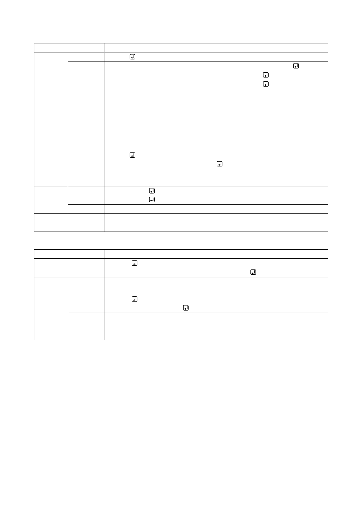
MSD-62 series Command Guide
@GLP / @SLP
TCP port num be r
Response
@GLP, port_1, port_2, port_3, port_4, port_5, port_6, port_7, port_8
Response
@SLP, connection_1, por t_1 (, connection_2, por t_2
)
Parameter
connection_1-8: Connec tion number
example
Response
@GLP,1100,1100,1100,23,23,23,80,80
Connection 1 to 3: 1100, Connec tion 4 to 6: 23, Connection 7 and 8: 80
Setting
Command
@SLP,8,6000
may be disabled. Change the environmental settings based on the MSD settings.
@GMC
MAC address
Response
@GMC, unit_1, unit_2, unit_3, unit_4, unit_5, unit_6
Parameter
unit_1: Upper bit of the MA C address to to uni t_6: lower bit of the MAC address
example
Response
@GMC,00,08,E5,5F,00,00
Remarks
Getting Command @GLP
Setting Command @S LP , connec tion_1, port_1 (, connection_2, port_2・・・)
・・・
0 = All connections, 1 = Connection 1 to 8 = Connection 8
port_1-8: TCP port number
23, 80, 1100, 5000 to 5999, 6000 to 6999
[Default]
Connection 1 to 3 = 1100, Connecti on 4 to 6 = 23,
Connection 7 to 8 = 80
Getting
Description Get ting the set TCP port number.
Command
@GLP
example
Description Setting port number of connecti on 8 to “6000” .
Remarks If IP address or RS-232C communicati on setting is changed, the communication
Getting Command @GMC
Getting
Description Getting the set MAC address.
Response
Command
@SLP,8,6000
00 to FF = 8 bit (in hexadecimal )
@GMC
MAC address: 00-08-E5-5F-00-00
-
84
Page 85
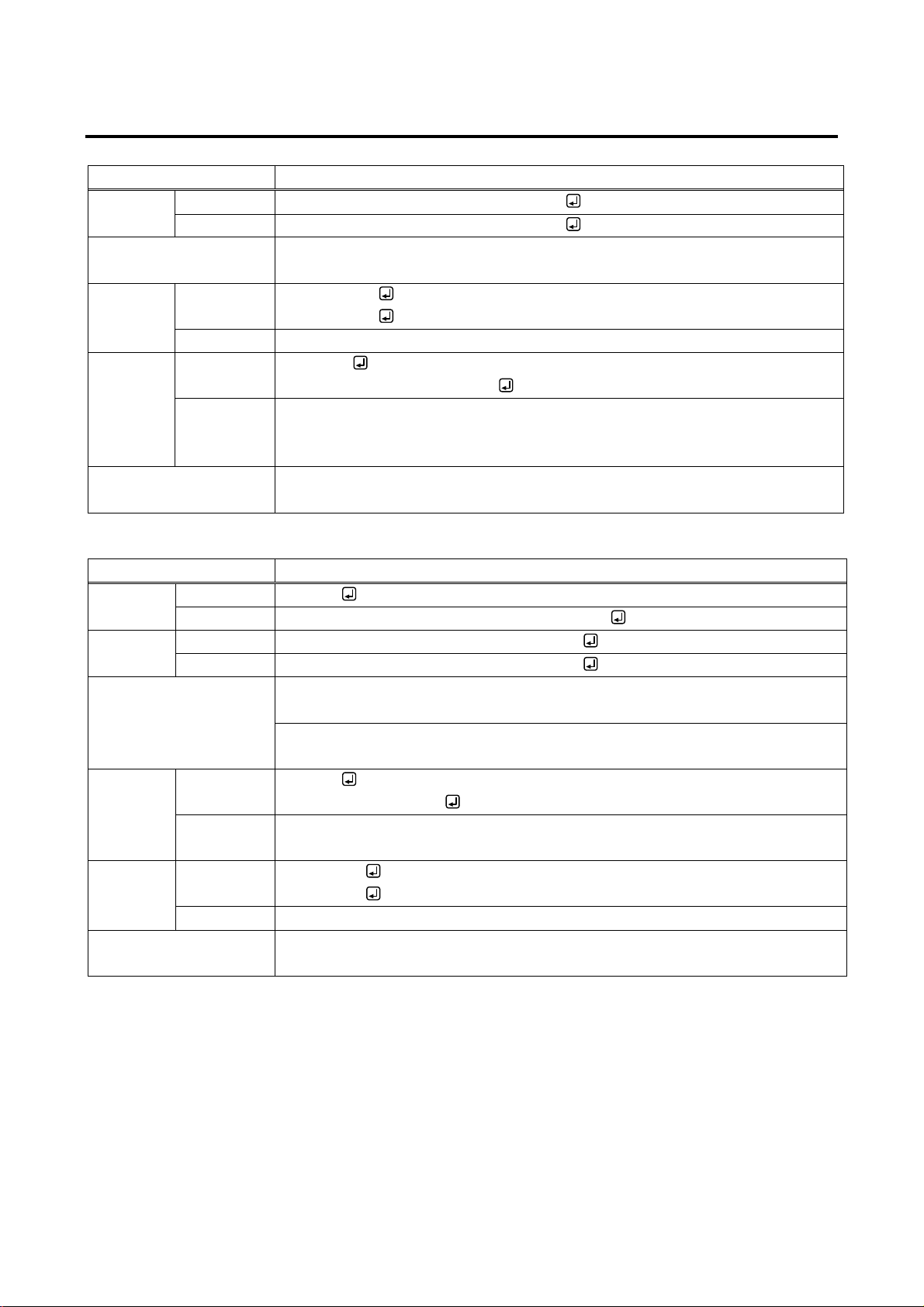
3.3.14 Control commands
@EXC
Executing control commands
Setting
Command
@EXC, command_1 (, comm and_2
)
Response
@EXC, command_1 (, comm and_2
)
example
Response
@EXC,1,2,3
example
Response
@EXC,6,RECV:POWER OFF
Description
Executing COMMAND 6.
returned. In this example, “POWER OFF” is received from the t ar get devic e.
Remarks
Since the result is ret ur ned aft er c ontrol command execution is complete,
@GDS / @SDS
Power but ton of sink device
0 = OFF, 1 = ON
0 = All outputs, 1 = OUT1 to 8 = OUT8
example
Response
@GDS,1,1,1,1,1,1,1,1
OUT1 and OUT8 powered ON
Setting
Command
@SDS,1,1
it sometimes may take a time for response.
・・・
・・・
Parameter command_1-5: Control command
1 = COMMAND 1 to 32 = COMMAND 32
Setting
Description Executing COMMAND 1→2→3 in order.
Setting
Command
Command
@EXC,1,2,3
@EXC,6
If a command to display received data is executed, the received result is
it sometimes may take a time for response.
MSD-62 series Command Guide
Getting Command @GDS
Response @GDS, onoff_1, onoff_2, onoff_3, …, onoff_8
Setting Command @S DS , ch_1, onoff_1 (, ch_2, onoff_2・・・)
Response @SDS, ch_1, onoff _1 ( , ch_2, onoff_2・・・)
Parameter onoff_1-8: Power button of si nk device
ch_1-8: Output channel
Getting
Description Get ting the power button status of sink dev ic e.
example
Description Setting the power button of the sink dev ic e that is connected OUT1 to ON.
Remarks Since the result is ret ur ned aft er c ontrol command execution is complete,
Command
Response
@GDS
@SDS,1,1
85
Page 86
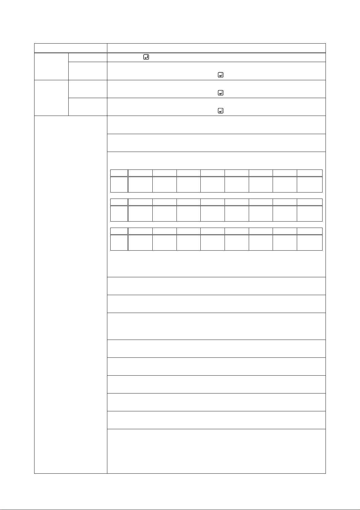
MSD-62 series Command Guide
@GEC / @SEC
Control command (Communi cat io n co mmand )
Response
@GEC, no, delay, port, m em o, lengt h, command, timeout, retry, interval,
retryover, displ ay (, r ecv_1, recv_2
)
Response
@SEC, no, delay, port, mem o, lengt h, command, timeout, retr y , interval,
1 to 32
bit 7 6 5 4 3 2 1 0
1
bit
15
14
13
12
11
10 9 8
bit
23
22
21
20
19
18
17
16
0 to 30
command: Send comm and data
hexadecimal).
0 to 99
0 = 0 sec. to 99999 = 99.999 sec.
retryover: Processing at retry over
0 = communication comm and c ontrol
recv_1-32: Presence or absence of response command check
For set commands, the reply command number to be checked can be specified.
Getting Command @GEC, no
retryover, displ ay (, r ecv_1, recv_2・・・)
Setting Command @S E C, no, delay , port, memo, length, command, timeout, retry, interval,
・・・
retryover, displ ay (, r ecv_1, recv_2・・・)
Parameter no: Control command num ber
delay: Delay time
0 = 0 sec. to 999999 = 999.999 sec.
port: Output port
1 to 16713725
port
port
port OUT8B OUT7B OUT6B OUT5B OUT4B OUT3B OUT2B OUT1B
LAN
6
-
LAN 5 LAN 4 LAN 3 LAN 2 LAN
IN6B IN5B
- -
LOOP
BACK
“1” is for the bit of the output port to send a command (Since bit 1, 11, 12, 15 are
not used, they are al ways “0”). For ex am ple, if you want to send a command
fr om RS-232C CH1, specify “1”. If sending a command from LAN 2, specify “8”.
memo:
Up to 14 characters of 20 to 7D except 2C (,).
length: Data size of send command (the number of bytes)
Specify length × 2 digits with 0 to 9, A to F, a to f: (4 bit per digit in
timeout: Time-out dur ation
0 = 0 sec. to 99999 = 99.999 sec.
retry: The number of retries
-
LAN
8
RS-232C
LAN
7
interval: Retry interval
0 = Stop processing, 1 = Continue pr oc essing
display: Displaying received data
1 to 32
For get commands, reply command numbers are separated from eac h other by
a comma.
86
Page 87
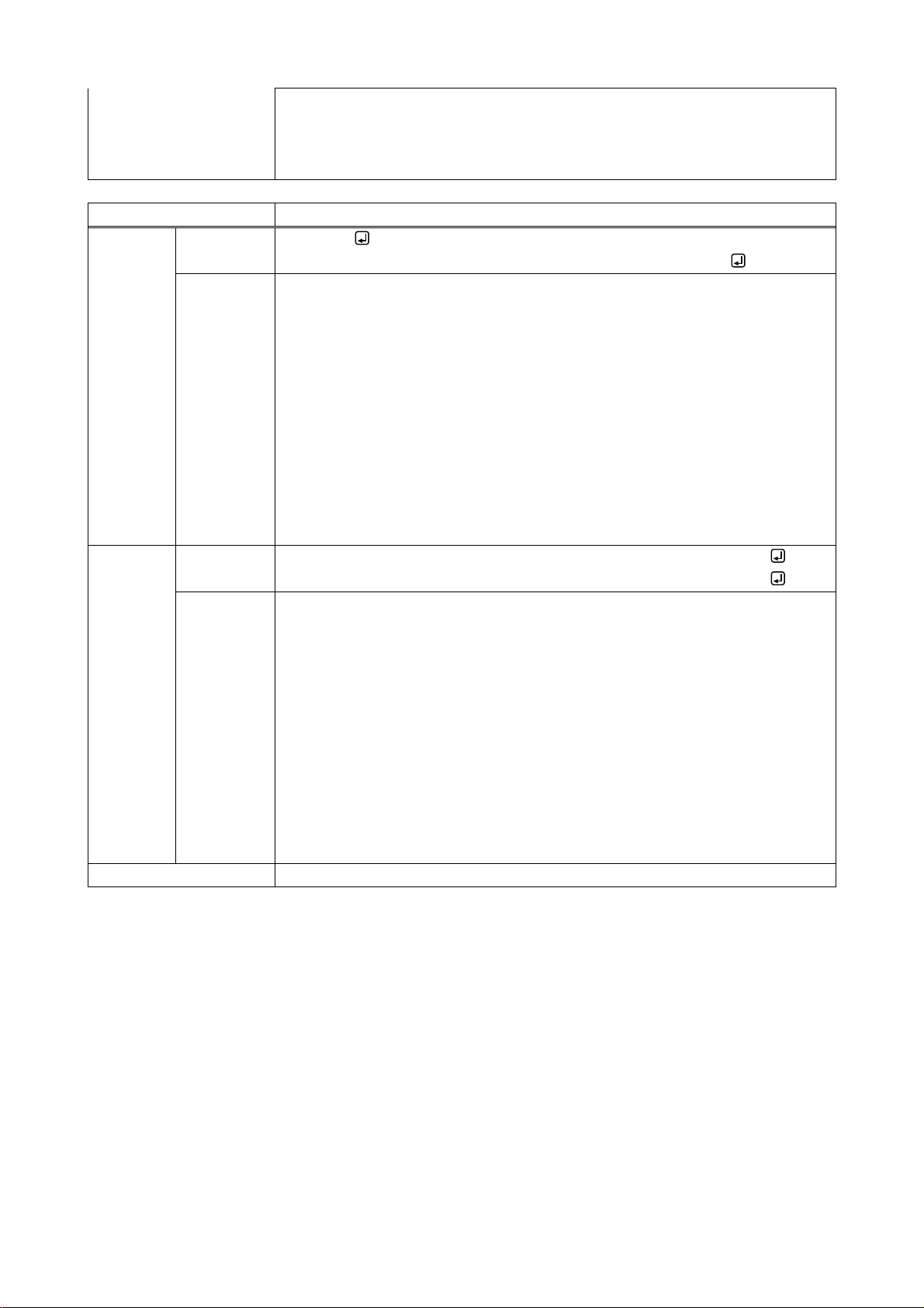
MSD-62 series Command Guide
Up to 32 commnads can be specified by separat ing them by a comma.
@GRC / @SRC Response command
@GEC / @SEC
Control command (Communi cat io n co mmand ) (cont’ d)
example
Response
@SEC,2,0,1024,IN1 SELECT,10,405353572C312C310D0A,0,0,0,1,0
Response command: Not check ed
If you send only parameter s of r eply c ommand number you want to chec k , the
reply commands without sent parameter are automatically set to “not check”.
Register reply commands i n “
”.
Getting
example
Description Get ting settings registered i n c ontrol c ommand 1.
Setting
Description Setting control command 2 as follows:
Remarks -
Command
Response
Command
@GEC,1
@GEC,1,10,1,POWER,7,5057204F4E0D0A,1000,2,500,0,0,1,2
・Delay: 10 ms
・Output port: RS-232C connector
・Memo: POWER
・Data size: 7 bytes
・Command data: PW ON CR LF (ASCII codes)
・Timeout: 1000 ms
・Retry: 2 times
・Retry interval: 500 ms
・Retry over: Stop
・Received data: Not displ ay ed
・Response command: Check 1 and 2
@SEC,2,0,1024,IN1 SELECT,10,405353572C312C310D0A,0,0,0,1,0
・Delay: 0 ms
・Output port: LOOP BACK
・Memo: IN1 SELECT
・Data size: 10 bytes
・Command data: @SSW,1,1 CR LF (ASCII codes)
・Timeout: 0 ms
・Retry: 0 time
・Interval: 0 ms
・Retry over: Execute
・Received data: Not displ ay ed
・
87
Page 88
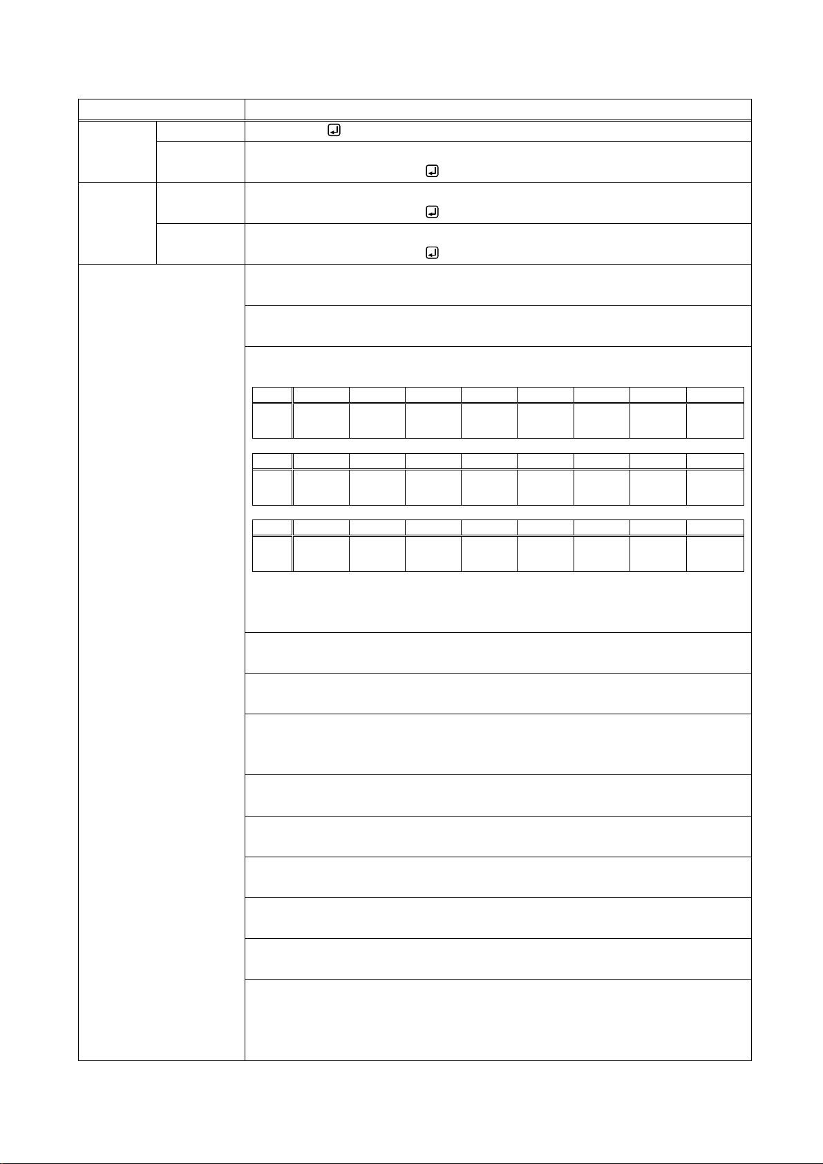
MSD-62 series Command Guide
@GEC / @SEC
Control command (Di spl ayin g recei ved data)
Response
@GEC, no, delay, port, m em o, lengt h, command, timeout, retry, interval,
retryover, displ ay , delimiter
Response
@SEC, no, delay, port, mem o, lengt h, command, timeout, retr y , interval,
1 to 32
bit 7 6 5 4 3 2 1 0
bit
15
14
13
12
11
10 9 8
bit
23
22
21
20
19
18
17
16
0 to 30
command: Command dat a
hexadecimal).
timeout: Time-out dur ation
0 to 99
0 = 0 sec. to 99999 = 99.999 sec.
retryover: Processing at retry over
1 = in ASCII codes, 2 = in hexadecimals
delimiter
100 = Not monitor
Getting Command @GEC, no
retryover, displ ay , delimiter
Setting Command @S E C, no, delay , port, memo, length, command, timeout, retry, interval,
retryover, displ ay , delimiter
Parameter no: Control command num ber
delay: Delay time
0 = 0 sec. to 999999 = 999.999 sec.
port: Output port
1 to 16738301
port
port
port
LAN 6 LAN
5
-
OUT8B OUT7B OUT6B OUT5B OUT4B OUT3B OUT2B OUT1B
IN6B IN5B
LAN
4
LAN
3
LAN
- -
2
“1” is for the output port to send a command (Since bit 1, 11, 12, 15 are not used,
they are always “0”). For ex am ple, if you want to send a command to RS-232C,
specify “1”. If sending a c ommand to LAN 2, specify “8”.
memo:
Up to 14 characters of 20 to 7D except 2C (,) from ASCII codes.
length: Command data si z e (the num ber of bit es)
Specify length × 2 digits wit h 0 to 9, A to F, a to f = 4 bit per digit (in
0 = 0 sec. to 99999 = 99.999 sec.
retry: The number of retires
LAN
1
LOOP
BACK
-
LAN
8
RS-232C
LAN
7
interval: Retry interval
0 = Stop processing, 1 = Continue pr oc essing
display: Displaying received data
2 digits of 0 to 9, A to F, a to f = 4 bit per digit (in hexadecimal) for monitoring
delimiter
88
Page 89
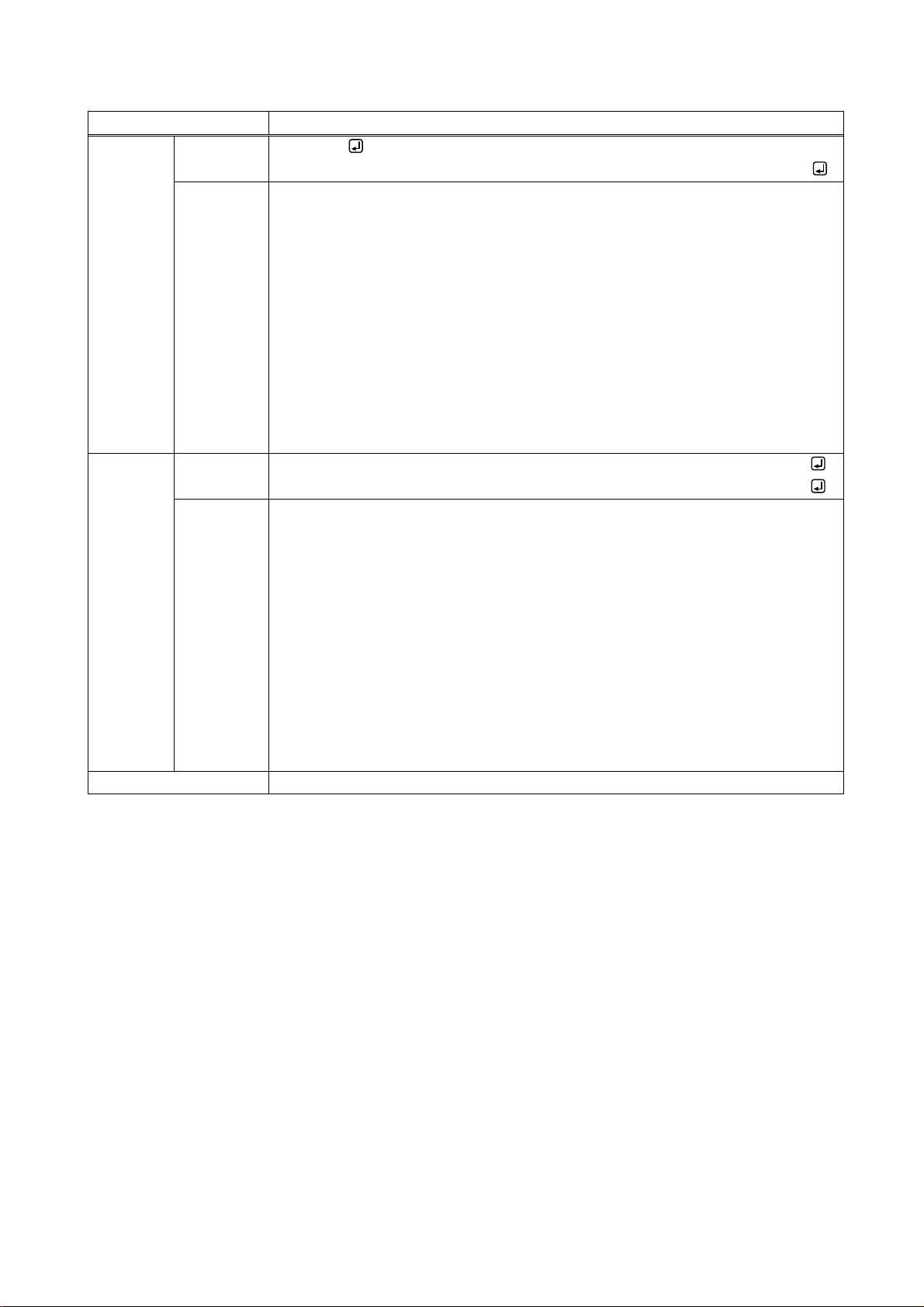
MSD-62 series Command Guide
@GEC / @SEC
Control command (Di spl ayin g recei ved data) (cont’d)
example
Response
@GEC,3,0,8,POWE R STATUS,9,47455420504F570D0A, 2000,2,200,0,1,0D
example
Response
@SEC,3,0,8,POWER STATUS ,9,47455420504F570D0A,2000,2,200,0,1,0D
Description
Setting contr ol c ommand 3 as follows:
Delimiter: 0D in hex (CR =ASCII c odes)
Remarks
Getting
Description Getting settings of control comm and 3.
Setting
Command
Command
@GEC,3
・Delay time: 0 ms
・Output port: LAN2
・Memo: POWER STATUS
・Data size: 9 bytes
・Command data: GET POW CR LF (ASCII codes)
・Timeout: 2000 ms
・Retry: 2 times
・Retry interval: 200 ms
・Retryover: Stop
・Received data: Displayed in ASCII codes
・Delimiter: 0D in hex (CR =ASCII c odes)
@SEC,3,0,8,POWER STATUS ,9,47455420504F570D0A,2000,2,200,0,1,0D
・Delay time: 0 ms
・Output port: LAN2
・Memo: POWER STATUS
・Data size: 9 bytes
・Command data: GET POW CR LF (ASCII codes)
・Timeout: 2000 ms
・Retry: 2 times
・Retry interval: 200 ms
・Retryover: Stop
・Received data: Displayed in ASCII codes
・
-
89
Page 90
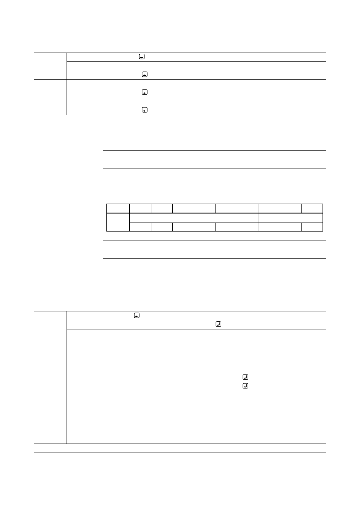
MSD-62 series Command Guide
@GEC / @SEC
Control command (contact closure)
Response
@GEC, no, delay, port, m em o, ccno_1, c c _1, pulse_1 (, ccno_2, cc_2,
pulse_2
)
Response
@SEC, no, delay, port, mem o, cc no_1, cc_1, pulse_1 (, ccno_2, cc_2,
1 to 32
2048= For contact closure control
Up to 14 characters of 20 to 7D except 2C (,) from ASCII codes.
ccno_1-8: Contact closure number
0 = OFF, 1 = ON, 2 = Toggle, 3 = Not control
example
Response
@GEC,7,20,2048,S CRE E N UP,1,1,100
example
Response
@SEC,6,50,2048,PROJECTOR ON,1,0,200,2,1,0
Description
Setting Control c ommand number 6 as follows:
Remarks
Getting Command @GEC, no
pulse_2・・・)
Setting Command @SEC, no, delay, port, mem o, cc no_1, cc_1, pulse_1 (, ccno_2, cc_2,
・・・
pulse_2・・・)
Parameter no: Control command number
delay: Delay time
0 = 0 sec. to 999999 = 999.999 sec.
port: Contact closure control
memo:
ccno 1 2 3 4 5 6 7 8 9
Contact
closure
CONTACT CLOSURE 1 CONTACT CLOSURE 2 CONTACT CLOSURE 3
CH1 CH2 CH3 CH1 CH2 CH3 CH1 CH2 CH3
cc_1-8: Contact closure control
pulse_1-8: pulse width
0 = Hold, 100 = 100 ms to 9990 = 9990 ms (by 10 ms)
Pulse width after the com pletion of contact closure.
Getting commands: onl y c ontact closure numbers to be controlled are replied.
Setting commands: specify only contact closure numbers to be controll ed. F or
contact closure numbers that do not specify parameter, “Not check” is set.
Getting
Command
@GEC,7
Description Getting settings of c ontrol command 7.
・Delay time: 20ms
・Memo: SCREEN UP
・Contact closure1’s CH1: ON f or 100 m s
・Other outputs: not c ontrolled.
Setting
Command
@SEC,6,50,2048,PROJECTOR ON,1,0,200,2,1,0
・Delay time: 50 ms
・Memo: PROJECTOR ON
・CH1 of contact closure1 : ON for 200 ms
・CH2 of contact closure : ON
・Other contact closure : Not c ontrolled
-
90
Page 91
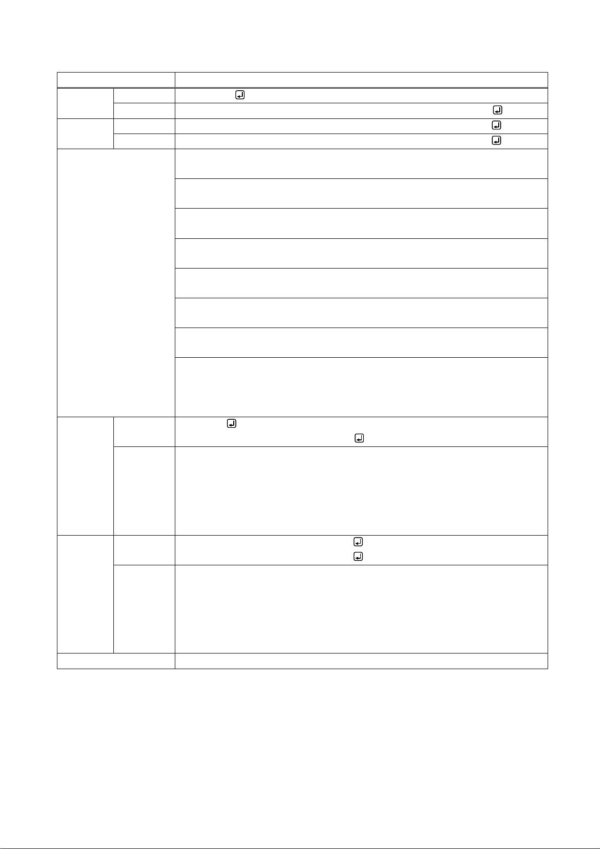
MSD-62 series Command Guide
@GEC / @SEC
Control command (CEC)
Response
@GEC, no, delay, port, m em o, err or, c h_1, cec _1 ( , ch_2, cec _2
)
Response
@SEC, no, delay, port, mem o, err or , ch_1, cec_1 (, ch_2, cec_2
)
Parameter
no: Control command num ber
0 = 0 sec. to 999999 = 999.999 sec.
port: CEC
Up to 14 characters of 20 to 7D except 2C (,) from ASCII codes.
0 = Stop processing, 1 = Continue pr oc essing
0 = Not controlled, 1 = POWER OFF, 2 = POWER ON
Getting commands: the c ontrol output connector and contr ol command are
commands. For outputs that do not specif y par am eter, “Not check” is set.
Getting
Command
@GEC,7
Other outputs: not c ontrolled.
Getting Command @GEC, no
・・・
Setting Command @SEC, no, delay, port, memo, error, ch_1, c ec _1 (, ch_2, c ec _2・・・)
・・・
1 to 32
delay: Delay time
4096 = For CEC control
memo:
error: P r oc essing if no r esponse f r om si nk dev ic e.
ch_1-8: Output channel
1 = OUT1 to 8 = OUT8
cec_1-8: Control command
separated from eac h other by a comma.
Setting commands: specify output connector to be controlled and control
example
Description Getting settings of control command 7.
Setting
example
Description S etting control command 7 as follows:
Remarks -
Response
Command
Response
@GEC,7,0,4096,DISPLAY1 ON,0,1,2
・Delay time: 0 ms
・Memo: DISPLAY1 ON
・Error: Stop
・OUT1 sink device: Turning on.
・
@SEC,7,0,4096,DISPLAY1 ON,0,1,2
@SEC,7,0,4096,DISPLAY1 ON,0,1,2
・Delay time:0 ms
・Memo: DISPLAY1 ON
・Error: Stop
・OUT1 sink device: Power ON.
・Other outputs: not c ontrolled.
91
Page 92
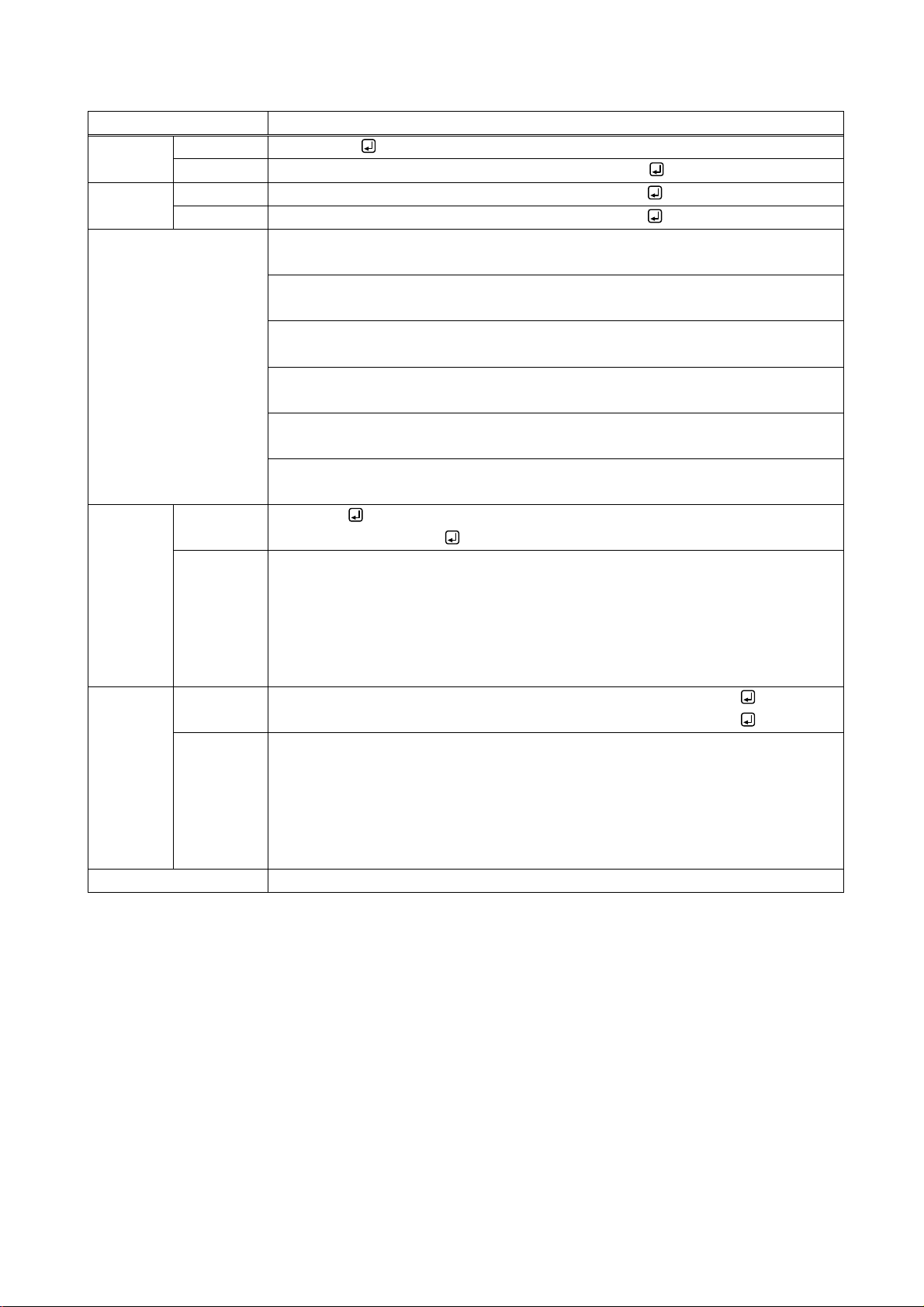
MSD-62 series Command Guide
@GRC / @SRC
Response command
Response
@GRC, no, process, length, command, mask, memo
Response
@SRC, no, process, length, command, mask, memo
Parameter
no: Response command number
0 = Stop, 1 = Continue, 2 = Resending commands
length: Reply c ommand dat a si z e (byt es)
length × 2 digits with 0 t o 9, A to F, a to f = 4 bit per digit (in hexadecimal)
length × 2 digits with 0 t o 9, A to F, a to f = 4 bit per digit (in hexadecimal)
example
Response
@GRC,2,0,1,40,40,NG
Description
Getting settings of r eply command 2:
Memo: NG (no good)
Setting
Command
@SRC,1,1,9,52454356204F4B0D0A,FFFFFFFFFFFFFFFFFF,OK
Getting Command @GRC, no
Setting Command @SRC, no, process, length, command, mask, memo
1 to 32
process
0 to 30
command: Reply command dat a
mask: Mask data
memo:
Up to 14 characters of 20 to 7D except 2C (,) from ASCII codes.
Getting
Command
@GRC,2
・Processing: Stop
・Data size: 1 byte
・Command data: 40 (in hex)
・Mask data: 40 (checking the second bit from the top)
・
example
Description Setting reply command 1 as follows:
Remarks -
Response
@SRC,1,1,9,52454356204F4B0D0A,FFFFFFFFFFFFFFFFFF,OK
・Processing: Conti nue
・Data size: 9 bytes
・Command data: RECV OK CR LF (ASCII)
・Mask data: ALL: FF (checki ng all bits)
・Memo: OK
92
Page 93
@GCC / @SCC
Control command link
Response
@GCC, event, c_1 (, c_2, c_3
)
Response
@SCC, event, c_1 (, c_2, c_3
)
Parameter
event: Control c ommand execution conditi on
[Table 3.2]
@GEC / @SEC Control command (CEC)
example
Response
@GCC,19,5,2,1
Description
Getting cont r ol commands that will be executed when the MSD is powered on.
example
Response
@SCC,19,5,2,1
Remarks
Getting Command @GCC, event
・・・
Setting Command @SCC, event, c_1 (, c_2, c_3・・・)
・・・
MSD-62 series Command Guide
For settable v alues, see the
c_1-10: Send command
0 = Not link [Default], 1 to 32 = Control comm and 1 to 32
Control commands that ar e r egistered in one of the following commands can be
linked.
@GEC / @SEC Control command (Communication command),
@GEC / @SEC Control command (Displaying received data),
@GEC / @SEC Control command (contact closure),
Getting
Setting
Description Ex ec uting in order of control command 5, 2, and 1 when the MSD is powered on.
Command
Command
@GCC,19
Executing in or der of c ontrol c ommand 5, 2, and 1.
@SCC,19,5,2,1
-
.
.
93
Page 94
MSD-62 series Command Guide
7
8
9
10
11
12
13
14
15
16
25
27
28
29
30
31
32
33
34
35
36
[Table 3.2] Parameter of control command execution condition
event
1 COMMAND A-PLANE A 37 VIDEO:OUT1-IN1 73 VIDEO:OUT3-IN1
2 COMMAND A-PLANE B 38 VIDEO:OUT1-IN2 74 VIDEO:OUT3-IN2
3 COMMAND B-PLANE A 39 VIDEO:OUT1-IN3 75 VIDEO:OUT3-IN3
4 COMMAND B-PLANE B 40 VIDEO:OUT1-IN4 76 VIDEO:OUT3-IN4
5 COMMAND C-PLANE A 41 VIDEO:OUT1-IN5 77 VIDEO:OUT3-IN5
6
17
18
19
20
21
22
23
24
26
Execution condition
COMMAND C-PLANE B 42 VIDEO:OUT1-IN6 78 VIDEO:OUT3-IN6
COMMAND D-PLANE A 43 VIDEO:OUT1-IN7 79 VIDEO:OUT3-IN7
COMMAND D-PLANE B 44 VIDEO:OUT1-IN8 80 VIDEO:OUT3-IN8
COMMAND E-PLANE A 45 VIDEO:OUT1-OFF 81 VIDEO:OUT3-OFF
COMMAND E-PLANE B 46 AUDIO:OUT1-IN1 82 AUDIO:OUT3-IN1
COMMAND F-PLANE A 47 AUDIO:OUT1-IN2 83 AUDIO:OUT3-IN2
COMMAND F-PLANE B 48 AUDIO:OUT1-IN3 84 AUDIO:OUT3-IN3
COMMAND G-PLANE A 49 AUDIO:OUT1-IN4 85 AUDIO:OUT3-IN4
COMMAND G-PLANE B 50 AUDIO:OUT1-IN5 86 AUDIO:OUT3-IN5
COMMAND H-PLANE A 51 AUDIO:OUT1-IN6 87 AUDIO:OUT3-IN6
COMMAND H-PLANE B 52 AUDIO:OUT1-IN7 88 AUDIO:OUT3-IN7
COMMAND I-PLANE A 53 AUDIO:OUT1-IN8 89 AUDIO:OUT3-IN8
COMMAND I-PLANE B 54 AUDIO:OUT1-OFF 90 AUDIO:OUT3-OFF
POWER ON 55 VIDEO:OUT2-IN1 91 VIDEO:OUT4-IN1
POWER OFF 56 VIDEO:OUT2-IN2 92 VIDEO:OUT4-IN2
DISPLAY1 POWER ON 57 VIDEO:OUT2-IN3 93 VIDEO:OUT4-IN3
DISPLAY1 POWER OFF 58 VIDEO:OUT2-IN4 94 VIDEO:OUT4-IN4
DISPLAY2 POWER ON 59 VIDEO:OUT2-IN5 95 VIDEO:OUT4-IN5
DISPLAY2 POWER OFF 60 VIDEO:OUT2-IN6 96 VIDEO:OUT4-IN6
DISPLAY3 POWER ON 61 VIDEO:OUT2-IN7 97 VIDEO:OUT4-IN7
DISPLAY3 POWER OFF 62 VIDEO:OUT2-IN8 98 VIDEO:OUT4-IN8
DISPLAY4 POWER ON 63 VIDEO:OUT2-OFF 99 VIDEO:OUT4-OFF
DISPLAY4 POWER OFF 64 AUDIO:OUT2-IN1 100 AUDIO:OUT4-IN1
DISPLAY5 POWER ON 65 AUDIO:OUT2-IN2 101 AUDIO:OUT4-IN2
DISPLAY5 POWER OFF 66 AUDIO:OUT2-IN3 102 AUDIO:OUT4-IN3
DISPLAY6 POWER ON 67 AUDIO:OUT2-IN4 103 AUDIO:OUT4-IN4
DISPLAY6 POWER OFF 68 AUDIO:OUT2-IN5 104 AUDIO:OUT4-IN5
DISPLAY7 POWER ON 69 AUDIO:OUT2-IN6 105 AUDIO:OUT4-IN6
DISPLAY7 POWER OFF 70 AUDIO:OUT2-IN7 106 AUDIO:OUT4-IN7
DISPLAY8 POWER ON 71 AUDIO:OUT2-IN8 107 AUDIO:OUT4-IN8
DISPLAY8 POWER OFF 72 AUDIO:OUT2-OFF 108 AUDIO:OUT4-OFF
event
Execution condition
event Execution condition
94
Page 95
MSD-62 series Command Guide
114
115
116
117
118
120
130
132
133
134
135
136
137
138
140
[Table 3.3] Parameter of control command execution condition (cont’d)
event
109 VIDEO:OUT5-IN1 145 VIDEO:OUT7-IN1
110 VIDEO:OUT5-IN2 146 VIDEO:OUT7-IN2
111 VIDEO:OUT5-IN3 147 VIDEO:OUT7-IN3
112 VIDEO:OUT5-IN4 148 VIDEO:OUT7-IN4
113 VIDEO:OUT5-IN5 149 VIDEO:OUT7-IN5
119
121
122
123
124
125
126
127
128
129
131
139
141
142
143
144
Execution condition
VIDEO:OUT5-IN6 150 VIDEO:OUT7-IN6
VIDEO:OUT5-IN7 151 VIDEO:OUT7-IN7
VIDEO:OUT5-IN8 152 VIDEO:OUT7-IN8
VIDEO:OUT5-OFF 153 VIDEO:OUT7-OFF
AUDIO:OUT5-IN1 154 AUDIO:OUT7-IN1
AUDIO:OUT5-IN2 155 AUDIO:OUT7-IN2
AUDIO:OUT5-IN3 156 AUDIO:OUT7-IN3
AUDIO:OUT5-IN4 157 AUDIO:OUT7-IN4
AUDIO:OUT5-IN5 158 AUDIO:OUT7-IN5
AUDIO:OUT5-IN6 159 AUDIO:OUT7-IN6
AUDIO:OUT5-IN7 160 AUDIO:OUT7-IN7
AUDIO:OUT5-IN8 161 AUDIO:OUT7-IN8
AUDIO:OUT5-OFF 162 AUDIO:OUT7-OFF
VIDEO:OUT6-IN1 163 VIDEO:OUT8-IN1
VIDEO:OUT6-IN2 164 VIDEO:OUT8-IN2
VIDEO:OUT6-IN3 165 VIDEO:OUT8-IN3
VIDEO:OUT6-IN4 166 VIDEO:OUT8-IN4
VIDEO:OUT6-IN5 167 VIDEO:OUT8-IN5
VIDEO:OUT6-IN6 168 VIDEO:OUT8-IN6
VIDEO:OUT6-IN7 169 VIDEO:OUT8-IN7
VIDEO:OUT6-IN8 170 VIDEO:OUT8-IN8
VIDEO:OUT6-OFF 171 VIDEO:OUT8-OFF
AUDIO:OUT6-IN1 172 AUDIO:OUT8-IN1
AUDIO:OUT6-IN2 173 AUDIO:OUT8-IN2
AUDIO:OUT6-IN3 174 AUDIO:OUT8-IN3
AUDIO:OUT6-IN4 175 AUDIO:OUT8-IN4
AUDIO:OUT6-IN5 176 AUDIO:OUT8-IN5
AUDIO:OUT6-IN6 177 AUDIO:OUT8-IN6
AUDIO:OUT6-IN7 178 AUDIO:OUT8-IN7
AUDIO:OUT6-IN8 179 AUDIO:OUT8-IN8
AUDIO:OUT6-OFF 180 AUDIO:OUT8-OFF
event
Execution condition
95
Page 96
MSD-62 series Command Guide
@GTG / @STG
Toggle operation
Response
@GTG, event_1, toggle_1 ( , event_2, toggle_2
)
Response
@STG, event_1, toggle_1 (, event_2, toggl e_2
)
Parameter
event_1-9: Command executi on c ondition
0 = Disabled [Default], 1 = Enabled
Getting
Command
@GTG,1
COMMAND A: Toggle operation enabled.
example
Response
@STG,1,1
Description
Enabling COMMANDA’s toggle operation COMMAND A.
Remarks
@GUP / @SUP
Plane to be ex e c ut ed when po we r e d ON
Response
@GUP, event_1, pl ane_1 (, ev ent_2, plane_2
)
Response
@SUP, event_1, plane_1 (, event_2, plane_2
)
Parameter
event_1-9: Command executi on c ondition
0 = AUTO [Default], 1 = PLANE A, 2 = PLANE B
Getting
Command
@GUP,1
COMMAND A executes PLANE A.
example
Response
@SUP,1,1
Remarks
Getting Command @GT G, ev ent_1 (, event_2・・・)
・・・
Setting Command @STG, event_1, toggle_1 (, event_2, toggl e_2・・・)
・・・
0 = All control commands, 1 = COMMAND A to 9 = COMMAND I
toggle_1-9: Toggle operation
example
Response
@GTG,1,1
Description Getting the toggle operation of COMMA ND A.
Setting
Command
@STG,1,1
-
Getting Command @GUP, event_1 (, event_2・・・)
・・・
Setting Command @SUP, event_1, plane_1 (, event_2, plane_2・・・)
・・・
0 = All control commands, 1 = COMMAND A to 9 = COMMAND I
plane_1-9: Plane to be executed when powered ON
example
Response
@GUP,1,1
Description Getting the plane to be executed for COMMAND A.
Setting
Command
@SUP,1,1
Description Setti ng COMM A ND A to execut e PLANE A.
-
96
Page 97
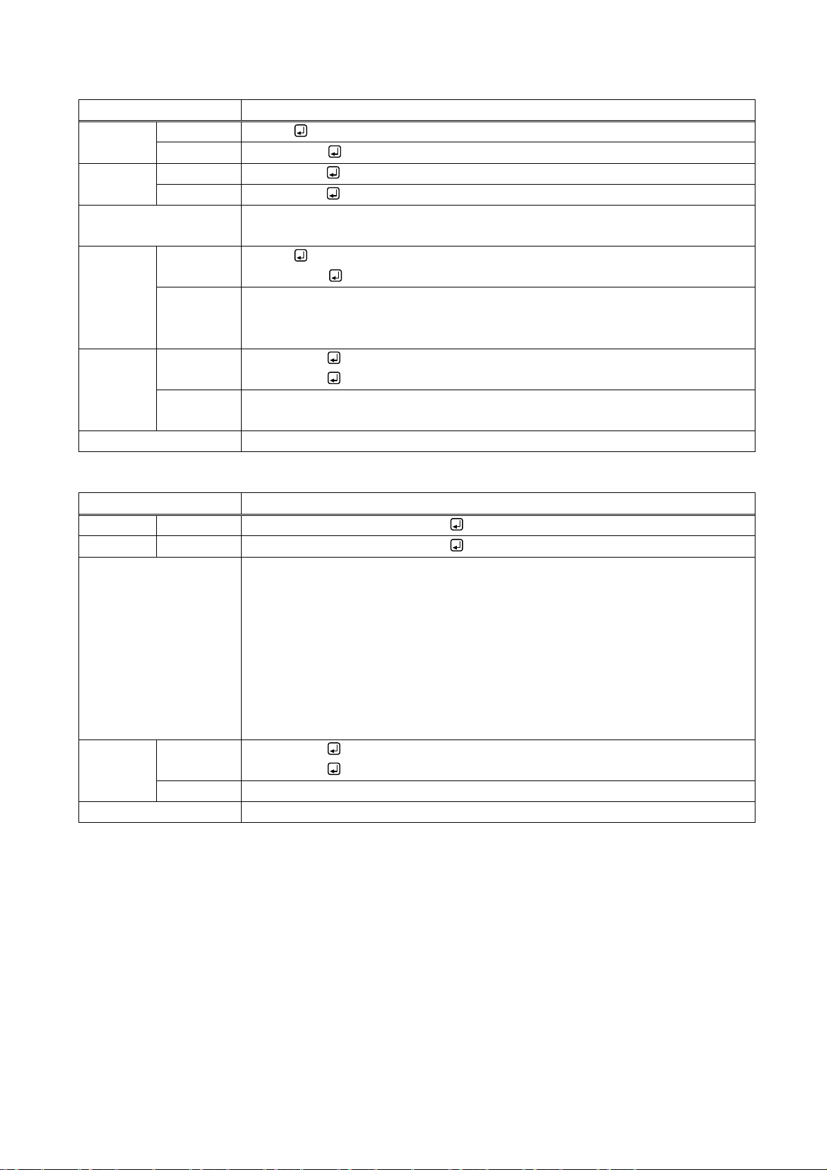
@GIT / @SIT
Ineffecti ve time du ring con t rol comman d execu t io n
Response
@GIT, time
Response
@SIT, ti me
Parameter
time: Invalid time
example
Response
@GIT,2000
Description
Getting ineffective time of control command ex ec ution.
after contr ol command star ts.
example
Response
@SIT,2000
Description
Setting ineff ec tive time during control c ommand exec ution t o 2000 m s. ( 2
@DEC
Initializing registered command and link
Setting
Command
@DEC, no_1 (, no_2, no_3
)
Response
@DEC, no_1 (, no_2, no_3
)
example
Response
@DEC,201
Getting Command @GIT
Setting Command @SIT, ti me
0 = 0 sec. to 999999 = 999.999 sec. [Default] 0 sec.
Getting
Command
@GIT
Disabling operation during control command execution or 2000 ms. (2 seconds)
MSD-62 series Command Guide
Setting
Command
@SIT,2000
seconds).
Remarks -
・・・
・・・
Parameter no_1-32: Com mands or links you want to initi alize
1 to 32: Control commands 1 to 32
101 to 132: Response comm ands1 to 32 ( “ 1xx”: xx is the response command
number)
【See: @GRC / @SRC Response command】
201 to 380: Control command links1 to 5 (“2xx”: xx is the control command
execution condition)
【See: @GCC / @SCC Control command link】
Setting
Command
@DEC,201
Description Delet ing the link between COMMAND A and PLANE A.
Remarks -
97
Page 98
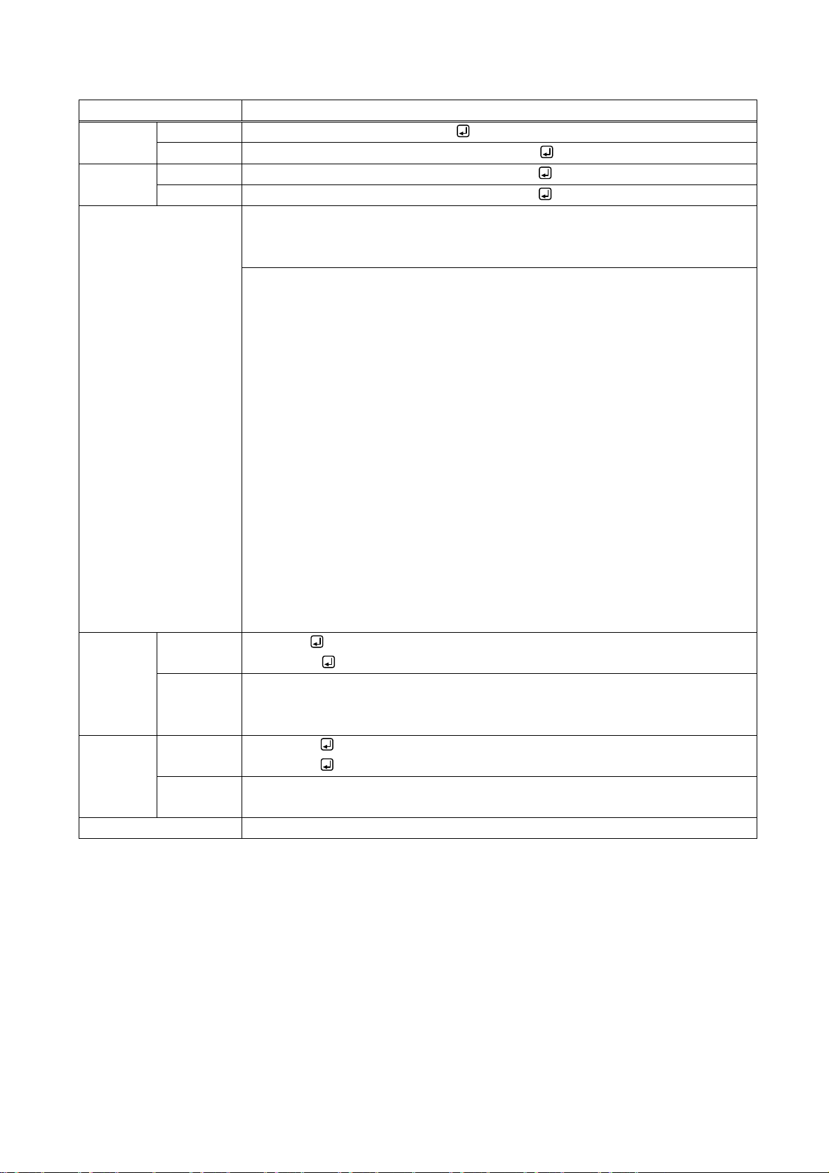
MSD-62 series Command Guide
@GTL / @STL
Lightin g c ondition of exe c ution but ton
Response
@GTL, switch_1, led_1 ( , switch_2, led_2
)
Response
@STL, switch_1, led_1 (, switch_2, led_2
)
Parameter
switch_1-9: Command execution button
1 = COMMAND A to 9 = COMMAND I
led_1-9 : Lighting condition
example
Response
@GTL,5,0
Description
Getting the lighting condition of the COMMAND E.
(If one PLANE is linked)
Setting
example
Command
Response
@STL,5,1
@STL,5,1
Description
Setting the COMMAND E to light while a command is being executed.
Getting Command @GT L, switch_1 ( , switch_2・・・)
・・・
Setting Command @STL, switch_1, led_1 (, switch_2, led_2・・・)
・・・
Getting
Command
0 = All command execution butt ons
If a control command( s) having only one PLANE, PLANE A or PLANE B is
linked to a control command execution button:
0 = Lights when a control command is registered. [Default]
1 = Lights while a control command is being executed.
If a control command( s) having two PLANEs, PLANE A and PLANE B is
linked to a control command execution button:
0 = A control command(s) that is linked to a button is executed by pressing
the desired button when the control command execution button
lights/blinks.
Lights: Control c ommand registered to PLANE A.
Blinks: Control c ommand registered to PLANE B.
1 = The control command that is link ed to a button is executed by pressing
a desired button when the contr ol command execution button
lights/goes out.
Lights: Control c ommand registered to PLANE A
Goes out: Control command registered to PLANE B
@GTL,5
Remarks -
The COMMAND E lights if a control c ommand is regi ster ed.
(If one PLANE is linked)
98
Page 99
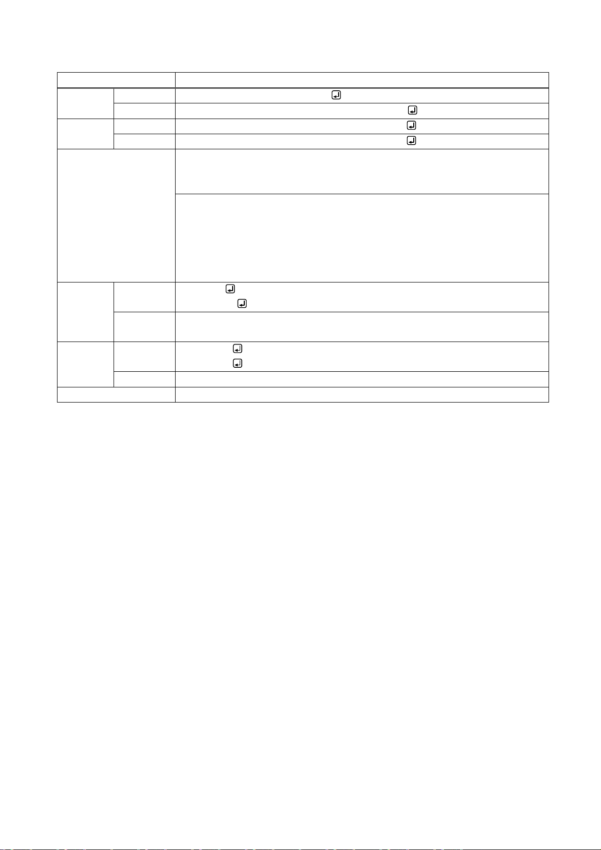
MSD-62 series Command Guide
@GTF / @STF
Blinking time of sink device power switch
Response
@GTF, switch_1, flash_1 (, switch_2, flash_2
)
Response
@STF, switch_1, flash_1 (, switc h_2, flash_2
)
Parameter
switch_1-13: Key group
10 = DISPLAY1 POWER to 17 = DISPLAY8 POWER
flash_1-13: Bli nki ng time
DISPLAY1 POWER to DISPLAY8 POWER = -1
The switch will be bli nk ed while c ontrol command is being executed.
Setting
Command
@STF,1,5
Getting Command @GT F, switc h_1 ( , switch_2・・・)
・・・
Setting Command @STF, switch_1, flash_1 (, switch_2, flash_2・・・)
・・・
0 = All keys, 1 = COMMAND A to 5 = COMMAND E
-1 = Links during control command execution,
0 = Not blink,
1 to 1000 = Blinks for 1 sec. to 1000 sec.
[Default] COMMAND A to COMMAND E = 0,
Getting
example
Description Getting blinki ng time of CO MMAND A.
example
Description Setting COMMAND A to blink 5 seconds aft er c ontrol command executi on star ts.
Remarks -
Command
Response
Response
@GTF,1
@GTF,1,-1
@STF,1,5
99
Page 100
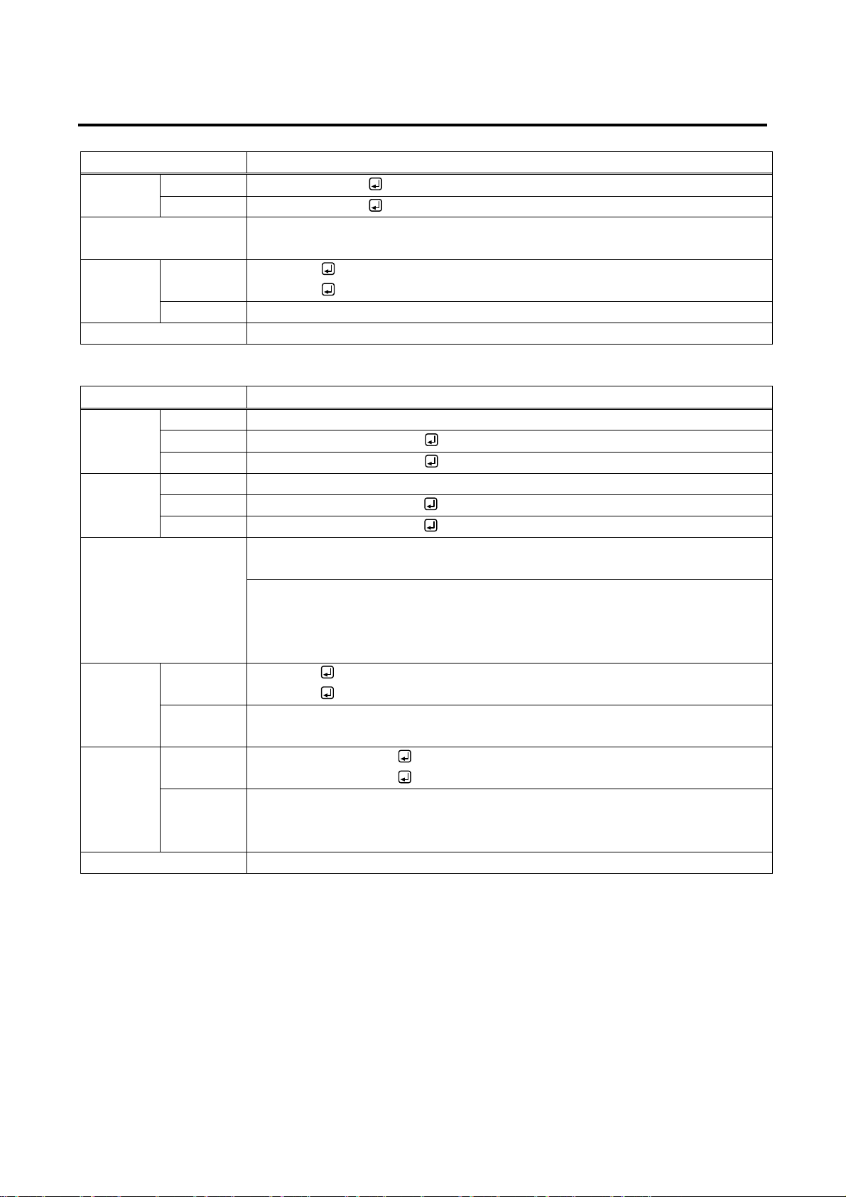
MSD-62 series Command Guide
@RCM
Loading crosspoint memory
Setting
Command
@RCM, memory
Response
@RCM, memory
example
Response
@RCM,1
@SCM / @SEM
Saving channel s to crosspoin t memory
Setting
Description
Overwriting all
Command
@SCM, memory (, name)
Response
@SCM, memory (, name)
Command
@SEM, memory (, name)
1 to 9
name: Mem ory nam e
example
Response
@SCM,2
changing the memor y name.
Setting
Command
@SEM,2,PATTERN2
3.3.15 Preset memory
Parameter memory: Crosspoint memory
1 to 9
Setting
Description Loading video and audio channels of crosspoint m em ory 1.
Remarks -
Command
@RCM,1
Setting Description Overwriting partly
Response @SEM, memory (, name)
Parameter memory: Crosspoint memory
Up to 10 characters using 20 t o 7D from ASCII codes.
If you do not specify memor y name, onl y crosspoint settings are sav ed without
changing the curr ent mem or y name.
Setting
Description Savi ng the current video and audio channels to c r osspoint memory 2 without
example
Description Savi ng the current video and audio channels to c r osspoint memory 2 with the
Remarks -
Command
Response
@SCM,2
@SEM,2,PATTERN2
name of “PATTERN2”. Out put sett ings that are set to Not Controlled are not
saved.
100
 Loading...