

IDK MSD-54 User Manual
POWE R
ON
OFF
DIG ITAL
MSD-5404
M ULT I
SW ITC HE R
OUT1
OUT2
OUT3
OUT4
IN1
IN3 IN4
IN5 IN6
IN7 IN8 IN9
OFF
POWER
DISPLAY
1
2
3
4
IN2
MENU/SET
ESC
COMMAND
E
COMMAND COMMAND COMMAND COMMAND
A B C D
V&A VIDEO AUDIO
SWITCHING M ODE
PRESET LOAD
COMMAND
IDK Corporation
Presentation Switcher
MSD-54 SERIES
MSD-5401 / MSD-5402 / MSD-5403 / MSD-5404
MSD-5401SL / MSD-5402SL
<User’s Guide>
Ver. 1.0.0
●Thank you for choosing our presentation switcher.
●To ensure the best performance of this product, please read this Users Guide and Command Guide fully and
carefully before using your switcher and keep this manual beside the product.

MSD-54 SERIES User’s Guide
Trademarks
HDMI, H DMI lo go, and Hig h-Definition Multimedia Interface are either trademarks of HDMI Licensing LLC
or registered trademarks in the United States and other countries.
PJLink is a trademark in Japan, the United States, and other countries/regions.
Microsoft, Windows, Internet Explorer are either registered trademarks or trademarks of the Microsoft
Corporation in the United States and other countries.
All other company and product names mentioned in this manual are either registered trademarks or
trademarks of their respective owners. In this manual, the “®” or “™” marks may not be specified.
2

Before reading this manual
Waste Electrical an d Electr onic Equipm ent (WEEE), Directive 2 002/96/ EC (This dir ect ive is
● All rights reserved.
● Some of the contents in this users guide such as appearance diagrams, menu operations, communication
commands, and so on may differ depending on the version.
● This User’s guide is subject to change without notice. You can download the latest version from IDK’s
website at: http://www.idk.co.jp/en/index.html
The reference manual for the MSD consists of the following two volumes:
■ User’s Guide (this document):
Contains installation, connection, configuration ,and operating information for the MSD.
■ Command Guide: Please download the command guide from the website above.
Provides explanations and procedures for external control using serial and LAN communications.
FCC STATEMENT
This equipment has been tested and found to comply with the limits for a Class A digital device, pursuant to
part 15 of the FCC Rules. These limits are designed to provide reasonable protection against harmful
interference when the equipment is operated in a commercial environment. This equipment generates, uses,
and can radiate radio frequency energy and, if not installed and used in accordance with the instruction
manual, may cause harmful interference to radio communications. Operation of this equipment in a residential
area is likely to cause harmful interference and the user will be required to correct that interference at their
own expense.
CE MARKING
This equipment complies with the essential requirements of the relevant European health, safet y and
environmental protection legislation.
WEEE MARKING
only valid in the EU.).
This equipment complies with the WEEE Directive (2002/96/EC) marking requirement.
The left marking indica tes that you mus t not discard this electrical/e lectronic equipment in
domestic household waste.
3
MSD-54 SERIES User’s Guide
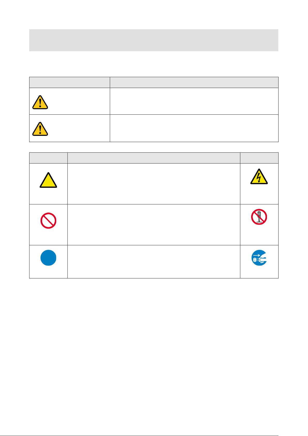
Enforcement Symbol
Description
Symbol
Description
Example
Instruction
Unplug
Caution
Warning
Safety instructions
Read and understand all safety and operating instructions before using this device. Follow all instructions and
cautions as detailed in this document.
Caution
Prohibition
Indicates the presence of a hazard that may result in death or serious
personal injury if the warning is ignored or the equipment is handled
incorrectly.
Indicates the presence of a hazard that may cause minor personal
This symbol is indicated to alert the user. (Warning and caution)
This symbol is intended to prohibit the user from actions.
injury or property damage if the caution is ignored or the equipment is
handled incorrectly.
Electrical
Hazard
Do not
disassemble
This symbol is intended to instruct the user.
4
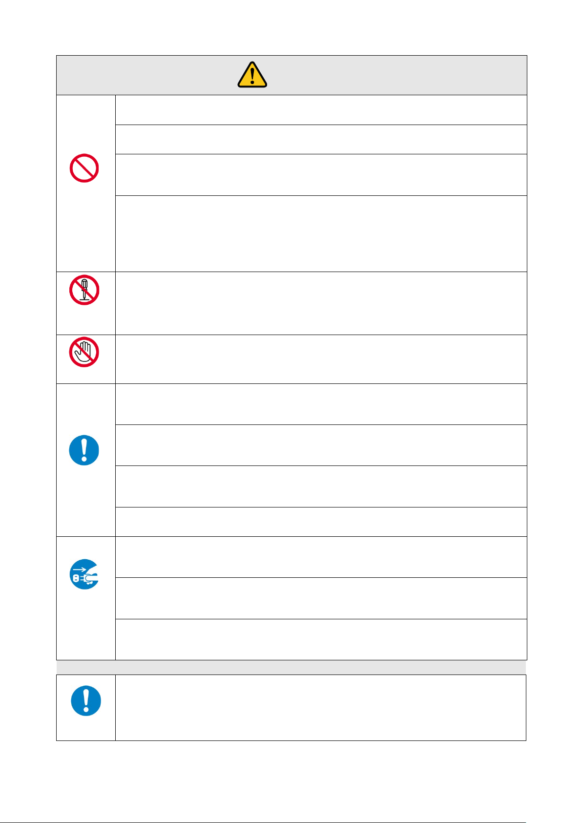
Do not place the product in any unstable place.
Install the product to a horizontal and stable place. Otherwise, it may fall/turn over and lead to injury.
Do not place the product in any environment with vibration.
Otherwise, it may move/fall and lead to injury.
Keep out any foreign objects.
the vent holes.
For power cable/ plug:
damaged, contact IDK.
Do not repair, modify or disassemble.
In the event of lighting or thunder, do not touch the main unit or cables such as power
For installation:
IDK. Otherwise, it may cause fire, electric shock, injury, or property damage.
Set the power plug in a convenient place to unplug easily.
you do not use it for a long period.
Plug the power plug into appropria te outlet completely.
loosened outlet.
Clean the power plug regularly.
If the plug is covered in dust, it may cause fire due to reduced insulating power.
Unplug immediately if the product smokes, makes unusual noise, or smells.
product stops smoking, contact IDK.
Unplug immediately if you drop the product or if the cabinet is damaged.
repair, contact IDK.
Unplug immediately if water or other objects are directed inside.
contact IDK.
For connection
Warning
Prohibition
Do not
disassemble
Do not touch
In order to avoid fire or electric shock, do not allow foreign objects, such as metal and paper, to enter the product from
● Do not scratch, heat, or modify, including extending them.
● Do not pull, put heavy stuff on them, or pinch them.
● Do not bend, twist, or tie them together forcefully.
If they are used in those states continuously, it may cause fire or electric shock. If power cables/plugs become
Since the product includes high-voltage part, those actions may cause fire or electric shock. For internal inspections
or repairs, contact IDK.
cable and LAN cable.
Contact may cause electric shock
Instruction
Unplug
The product is intended to be installed by skilled technicians. For installation, please contact a system integrator or
You can easily unplug in case of any extraordinary failure or abnormal situation, and it also helps for unplugging w hen
If the plug is plugged incompletely, it may overheat which causes electrical shock or fire. Do not use damaged plug or
If you continue to use the product under those situations, it may cause electric shock or fire. After confirming that the
If you continue to use the product under those situations, it may cause electrical shock or fire. For maintenance and
If you continue to use it under those situations, it may cause electrical shock or fire. For maintenance and repair,
Difference in ground potential among the product and peripheral devices may cause electric shock or damage of the
device. When using cables to connect devices, including connection of long-distance transmission, unplug the power
cables of all related devices.
Instruction
After connecting signal/control cables of each device, plug in the power cables of each device.
5
MSD-54 SERIES User’s Guide
For installation
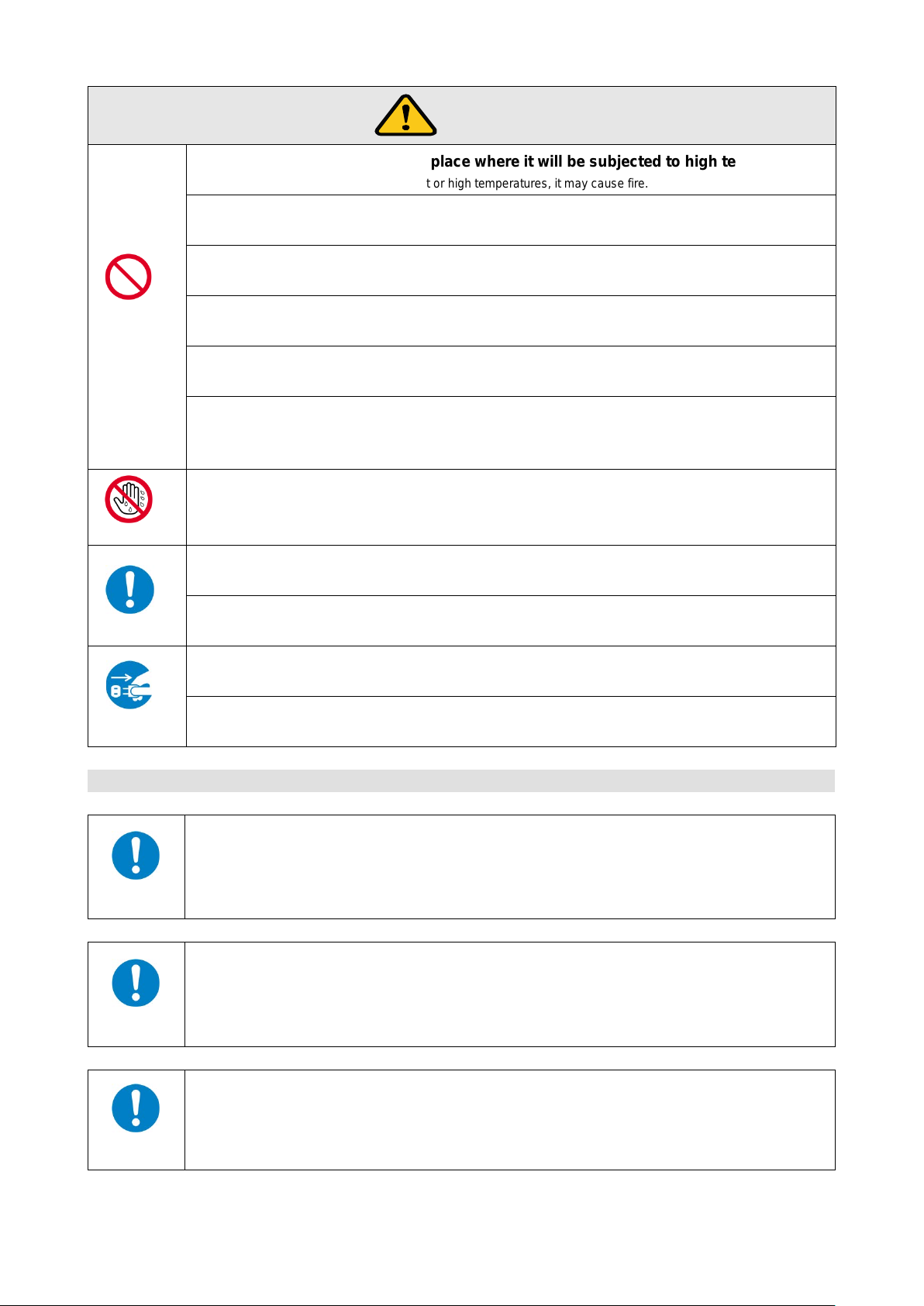
Do not place the product in humid, oil smoke, or dusty pl ace.
Do not put heavy items on the product.
Caution
Prohibition
No wet hands
Instruction
Do not place the product in any place where it will be sub jected to high temperatures.
If the product is subjected to direct sunlight or high temperatures, it may cause fire.
If the product is placed near humidifiers or dusty area, it may cause fire or electric shock.
Do not block the vent holes.
If ventilation slots are blocked, it may cause fire or failure due to internal heat.
It may fall/turn over and lead to injury.
Do not exceed ratings of outlet and wiring devices.
If several plugs are put in an outlet, it may cause fire and electric shock.
Use only the provided AC adapter and power cable.
If non-compliant adapter or power cables is used, it may cause fire or electrical shock. Use the provided AC power
connection cable. If you want to use your product in other countries that use different AC power cables, contact IDK.
Do not plug or unplug with wet hands.
It may cause electrical shock.
Use and store the product within the specified temperature/humidity range.
If the product is used outside the range continuously, it may cause fire or electric shock.
Turn off devices when they are connected to another d evice.
It may cause fire or electric shock.
Unplug
Unplug the power plug if you do not use the product for a long period.
In case of defect, it may cause fire.
Unplug the power plug before cleaning.
It may cause electric shock.
For rack mount devices:
Mount the product to the rack meeting EIA standards, and maintain spaces above and below
for air cooling. For your safety, attach an L-shape bracket in addition to the mount bracket kit
for the front panel in or der to balance the weight.
Instruction
For devices with rubber feet:
Never insert only the screws into the holes after removing the rubber feet. It may lead to
damage when the screws contact electrical circuit or parts inside of the product.
To put the rubber feet back on, use only provided rubber feet and screws.
Instruction
Altitude:
Do not place the product at elevations of 2,000 meters (6562 feet) or higher above sea level.
Failure to do so may shorten the life of the internal parts and result in malfunctions.
Instruction
6

Table of Contents
1 Included Items ............................................................................................................................................ 12
2 Product Outline ........................................................................................................................................... 13
3 Features ...................................................................................................................................................... 14
4 System Diagram ......................................................................................................................................... 15
5 Panels ......................................................................................................................................................... 16
5.1 Front Panel ........................................................................................................................................ 16
5.2 Rear Panel ........................................................................................................................................ 17
6 Installation ................................................................................................................................................... 18
6.1 Cabling Digital Input/Output Devices ................................................................................................ 18
6.2 Analog Video Input Connectors ........................................................................................................ 20
6.3 Serial Port .......................................................................................................................................... 21
6.4 LAN Port ............................................................................................................................................ 22
6.4.1 The number of TCP-IP connections ........................................................................................... 23
7 Basic Operations ........................................................................................................................................ 24
7.1 Selecting Input Channels .................................................................................................................. 24
7.2 VFD screen/Menu Operation Keys ................................................................................................... 25
7.3 Turning ON/OFF Display Devices ..................................................................................................... 26
7.4 Executing Control Commands .......................................................................................................... 27
7.5 Loading Cross Point .......................................................................................................................... 28
7.6 Locking/Unlocking Front Keys ........................................................................................................... 28
7.7 WEB Browser Control ....................................................................................................................... 29
7.8 Remote Control Application .............................................................................................................. 32
7.9 Factory Reset .................................................................................................................................... 32
7.10 Startup Time ...................................................................................................................................... 36
8 Settings ....................................................................................................................................................... 37
8.1 Menu List ........................................................................................................................................... 37
8.2 Input Signal Auto Detection ............................................................................................................... 46
8.3 Setting Position, Size, and Masking .................................................................................................. 47
8.3.1 Output resolutions ....................................................................................................................... 49
8.3.2 Aspect ratio control of output video ............................................................................................ 51
8.3.3 Aspect ratio control of input video............................................................................................... 52
8.3.4 Aspect ratio control ..................................................................................................................... 57
8.3.5 Overscan ..................................................................................................................................... 58
7

MSD-54 SERIES User’s Guide
Input position............................................................................................................................... 59
8.3.6
8.3.7 Input size ..................................................................................................................................... 61
8.3.8 Input masking.............................................................................................................................. 62
8.3.9 Input automatic sizing ................................................................................................................. 63
8.3.10 Output position ............................................................................................................................ 65
8.3.11 Output size .................................................................................................................................. 66
8.3.12 Output masking ........................................................................................................................... 68
8.3.13 Output automatic sizing .............................................................................................................. 70
8.3.14 Background color ........................................................................................................................ 71
8.3.15 Test pattern ................................................................................................................................. 72
8.4 Video Correction................................................................................................................................ 74
8.4.1 Input brightness .......................................................................................................................... 74
8.4.2 Input contrast .............................................................................................................................. 75
8.4.3 Hue ............................................................................................................................................. 76
8.4.4 Saturation .................................................................................................................................... 77
8.4.5 Black level ................................................................................................................................... 78
8.4.6 Input default color ....................................................................................................................... 79
8.4.7 Output brightness ....................................................................................................................... 80
8.4.8 Output contrast ........................................................................................................................... 81
8.4.9 Output default color .................................................................................................................... 82
8.5 Input Settings .................................................................................................................................... 83
8.5.1 No-signal input monitoring .......................................................................................................... 83
8.5.2 HDCP input enabled/dis ab l ed ..................................................................................................... 85
8.5.3 Input equalizer ............................................................................................................................ 87
8.5.4 Signal type of analog input ......................................................................................................... 88
8.5.5 Automatic detection of input video interruption ........................................................................... 89
8.6 Input Timing Settings ........................................................................................................................ 90
8.6.1 The total number of horizontal dots ............................................................................................ 91
8.6.2 Horizontal start position .............................................................................................................. 92
8.6.3 Horizontal display period ............................................................................................................ 93
8.6.4 Vertical start position .................................................................................................................. 94
8.6.5 Vertical display period ................................................................................................................. 95
8.6.6 Analog input automatic measurement ........................................................................................ 96
8.6.7 Automatic measurement of start position ................................................................................... 99
8.6.8 Automatic setting of input timing ............................................................................................... 101
8.6.9 Loading device data .................................................................................................................. 102
8.6.10 Registering device data ............................................................................................................ 104
8.6.11 Tracking .................................................................................................................................... 105
8.7 Output settings ................................................................................................................................ 106
8.7.1 Output equalizer ....................................................................................................................... 106
8.7.2 Output mode ............................................................................................................................. 107
8.7.3 Synchronous signal output with no input video ........................................................................ 108
8.7.4 Output video with no input video ............................................................................................... 109
8.7.5 Window transition effect ............................................................................................................ 110
8.7.6 Window transition speed ........................................................................................................... 112
8.7.7 Wipe color ................................................................................................................................. 114
8.7.8 HDCP output mode ................................................................................................................... 115
8

The number of HDCP retries .................................................................................................... 116
8.7.9
8.7.10 Deep Color ................................................................................................................................ 117
8.7.11 CEC (Consumer Electronics Control) ....................................................................................... 118
8.7.12 HDCP re-authorization .............................................................................................................. 120
8.8 Audio Settings ................................................................................................................................. 121
8.8.1 Output level ............................................................................................................................... 122
8.8.2 Output mute .............................................................................................................................. 123
8.8.3 Input selection ........................................................................................................................... 124
8.8.4 Input level .................................................................................................................................. 125
8.8.5 Output lip sync .......................................................................................................................... 126
8.8.6 Input lip sync ............................................................................................................................. 127
8.8.7 Sampling frequency of analog audio input ............................................................................... 128
8.8.8 Output connector ...................................................................................................................... 129
8.8.9 Multi-channel audio output ........................................................................................................ 130
8.8.10 Test tone ................................................................................................................................... 131
8.9 EDID (Extended Display Identification Data) .................................................................................. 133
8.9.1 EDID setting .............................................................................................................................. 133
8.9.2 PC resolutions........................................................................................................................... 135
8.9.3 HDTV resolutions ...................................................................................................................... 137
8.9.4 Deep Color ................................................................................................................................ 138
8.9.5 Audio format .............................................................................................................................. 139
8.9.6 Speaker configuration ............................................................................................................... 141
8.9.7 EDID Copy ................................................................................................................................ 143
8.10 Serial (COM) Port Settings .............................................................................................................. 144
8.10.1 Communication setting ............................................................................................................. 144
8.10.2 Operation mode ........................................................................................................................ 145
8.11 LAN Set tin gs ................................................................................................................................... 146
8.11.1 IP address ................................................................................................................................. 146
8.11.2 Subnet mask ............................................................................................................................. 147
8.11.3 Gateway address ...................................................................................................................... 148
8.11.4 Operation mode ........................................................................................................................ 149
8.11.5 TCP port number ...................................................................................................................... 152
8.11.6 Displaying MAC address .......................................................................................................... 153
8.12 Control Command Settings ............................................................................................................. 154
8.12.1 Control commands .................................................................................................................... 158
8.12.2 Reply commands ...................................................................................................................... 170
8.12.3 Command link ........................................................................................................................... 175
8.12.4 Command execution ................................................................................................................. 178
8.12.5 Invalid time ................................................................................................................................ 179
8.12.6 Initializing registered commands and associations .................................................................. 180
8.12.7 Command key lighting .............................................................................................................. 182
8.12.8 Flash time (Command keys and DISPLAY POWER keys) ...................................................... 183
8.13 Preset memory ................................................................................................................................ 184
8.13.1 Loading cross point ................................................................................................................... 184
8.13.2 Saving cross point .................................................................................................................... 185
8.13.3 Editing cross point .................................................................................................................... 186
8.13.4 Loading all settings ................................................................................................................... 188
9

MSD-54 SERIES User’s Guide
Saving all settings ..................................................................................................................... 189
8.13.5
8.13.6 Startup setting ........................................................................................................................... 191
8.14 Parallel ............................................................................................................................................ 192
8.14.1 Assigning functions ................................................................................................................... 193
8.14.2 Audio level ................................................................................................................................ 201
8.14.3 The number of clicks (Rotary encoder) .................................................................................... 202
8.14.4 Enable/Disable .......................................................................................................................... 203
8.14.5 Switching mode......................................................................................................................... 204
8.14.6 Toggle ....................................................................................................................................... 205
8.14.7 Chattering reduction ................................................................................................................. 206
8.14.8 Buzzer ....................................................................................................................................... 207
8.14.9 Analog input measurement ....................................................................................................... 207
8.14.10 Function initialization ................................................................................................................ 208
8.15 Tally ................................................................................................................................................. 209
8.15.1 Assigning functions ................................................................................................................... 210
8.15.2 Function initialization ................................................................................................................ 219
8.16 Bitmap ............................................................................................................................................. 220
8.16.1 Bitmap transfer.......................................................................................................................... 220
8.16.2 Bitmap output ............................................................................................................................ 223
8.16.3 Background color ...................................................................................................................... 224
8.16.4 Aspect ratio ............................................................................................................................... 225
8.16.5 Position ..................................................................................................................................... 227
8.16.6 Input bitmap channel assignment ............................................................................................. 228
8.16.7 Enabling/Disabling startup bitmap ............................................................................................ 229
8.16.8 Dividing memory ....................................................................................................................... 230
8.16.9 Input image capture .................................................................................................................. 233
8.17 Startup settings ............................................................................................................................... 236
8.17.1 DISPLAY POWER keys ............................................................................................................ 236
8.17.2 Control command keys ............................................................................................................. 237
8.17.3 Key lock .................................................................................................................................... 238
8.17.4 Tally outputs .............................................................................................................................. 239
8.18 Others .............................................................................................................................................. 240
8.18.1 Key lock mode .......................................................................................................................... 240
8.18.2 Key buzzer ................................................................................................................................ 241
8.18.3 Automatic key lock for control command keys ......................................................................... 242
8.18.4 DISPLAY POWER key pressing time ....................................................................................... 243
8.18.5 Input channel automatic linking ................................................................................................ 244
8.18.6 Top VFD screen ........................................................................................................................ 246
8.18.7 Input signal status ..................................................................................................................... 247
8.18.8 Display device status ................................................................................................................ 249
8.18.9 EDID information ...................................................................................................................... 251
8.18.10 Version information ................................................................................................................... 253
9 ASCII codes .............................................................................................................................................. 254
10 Specification ............................................................................................................................................. 256
11 Trouble shooting ....................................................................................................................................... 259
10

Fuse .......................................................................................................................................................... 268
12
11

1 Included Items
Make sure all items below are included in the package.
If any items are missing or damaged, please contact IDK.
・One (1) presentation switcher (main unit)
・One (1) RS-232C cable (1.8 meters; approximately 5.91 feet)
・One (1) power cord (1.8 meters; approximately 5.91 feet)
・Two (2) rack mounting brackets
・Cable clamps
Six (6) for MSD-5401 and MSD-5401SL
Seven (7) for MSD-5402 and MSD-5402SL
Eight (8) for MSD-5403
Nine (9) for MSD-5404
You can download the latest version of the User’s Guide from IDK’s website at:
http://www.idk.co.jp/en/index.html
MSD-54 SERIES User’s Guide
12
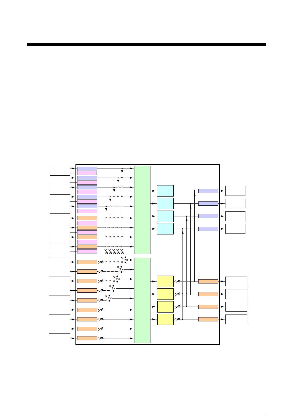
2 Product Outline
Video
Matrix
Switch
HDMI/DVI
Input (5 ch)
Scan
Converter
*1 Digital I/O supports HDMI signals and DVI signals.
*1 *2
*2 Digital-input audio: Can be converted into embedded or analog audio.
Analog
Audio
Output
(4 ch)
*3
Analog video input supports composite, S-Video, analog RGB and analog YPbPr signals.
Audio
Matrix
Switch
Analog
Audio Input
(9 ch)
Scan
Converter
Scan
Converter
Scan
Converter
Lip Sync
HDMI/DVI
Output
(4 ch)
*1
Analog
Video
Input (4 ch)
IN 6
D-sub15 pin
*3
IN 7
D-sub15 pin
IN 8
D-sub15 pin
IN 9
D-sub15 pin
IN 2
HDMI
IN 3
HDMI
IN 4
HDMI
IN 5
HDMI
IN 1
HDMI
EDID Emulator
EDID Emulator
EDID Emulator
EDID Emulator
EDID Emulator
EDID Emulator
A/D Converter
EDID Emulator
A/D Converter
EDID Emulator
A/D Converter
EDID Emulator
A/D Converter
IN 1
RCA pin jack
IN 2
RCA pin jack
IN 3
RCA pin jack
IN 4
RCA pin jack
IN 5
RCA pin jack
IN 6
RCA pin jack
IN 7
RCA pin jack
IN 8
RCA pin jack
IN 9
RCA pin jack
A/D Converter
A/D Converter
A/D Converter
A/D Converter
A/D Converter
A/D Converter
A/D Converter
A/D Converter
A/D Converter
Lip Sync
Lip Sync
Lip Sync
D/A Converter
OUT 4
RCA pin jack
OUT 4
HDMI
OUT 3
HDMI
OUT 2
HDMI
OUT 1
HDMI
D/A Converter
OUT 3
RCA pin jack
D/A Converter
OUT 2
RCA pin jack
D/A Converter
OUT 1
RCA pin jack
Output EQ
Output EQ
Output EQ
Output EQ
Input EQ
Input EQ
Input EQ
Input EQ
Input EQ
The MSD is a Presentation Switcher having a built-in scan converter with 9-input s and 1 to 4-outputs.
For video input, the MSD has five digital and four analog inputs, and the series can input the following signals:
HDMI, DVI, composite video, S-video, analog RGB, analog YPbPr signals. The MSD converts input video
signals up to QWXGA or 1080p and outputs them as HDMI or DVI signals.
For audio input, the series has five digital and nine analog inputs, and the series can output selected audio
signals as digital audio (HDMI signals) and analog audio. You can set audio level of each input and output
separately. The MSD also has the Lip Sync function to correct gaps between video and audio signals.
The MSD series includes RS-232C (2 ports), LAN, and parallel contacts as communication ports for external
control, which enables you to set or edit settings remotely. You can also control peripheral devices connected
to the MSD through RS-232C, LAN, Tally OUT and CEC by registering external control commands. For
external control commands, the wait function is available to switch the contact after cooling-down time passes
for power control of projectors and other devices.
You can execute external control commands using front panel keys, RS-232C, LAN, and parallel connectors,
and you can also execute them when operating the input switching keys and turning on the MSD.
[Figure 2.1] I/O diagram of Video/Audio signals
13

MSD-54 SERIES User’s Guide
3 Features
■For video
・ HDMI and DVI signals: HDCP (High-bandwidth Digital Content Protection system) is supported.
・ All input video signals including sources with HDCP can be switched speedily and free from sudden
screen disturbance.*
・ Various video formats such as NTSC, PAL, VGA to QWXGA and SDTV/HDTV (D1 to D5)
2
・ Anti-snow*
・ Analog video signals can be converted into digital video signals and can be output as HDMI or DVI signals.
・ Scan converter that converts sources up to QWXGA or 1080p and outputs them as HDMI or DVI signals
・ Aspect ratio control
・ Cable compensation circuits for digital input and output
■For audio
・ Analog audio can be output as HDMI signals (embedded output) and can be separated from embedded
audio of HDMI signals (analog output).
・ Multi-channel linear PCM can be down-mixed to 2-channel linear PCM.
■For control
・ Adjust function for display conditions, such as position, size, brightness, contrast, and so on
・ Projectors can be turned off using front panel keys.
・ Meets the PJLink (class1) standard protocol for projector control regulated by JBMIA (Japan Business
Machine and Information System Industries Association).
・ Power control of display devices using CEC.*
■Others
・ Connection Reset*
・ EDID emulation for all inputs
1
For models MSD-5401 to MSD-5404, seamless switching is available, which displays a black frame or
*
black background between two images.
For MSD-5401SL and MSD-5402SL, truly seamless switching is available with transition effect of cut,
dissolve, and wipe.
2
The anti-snow function automatically fixes snow noise that is a specific symptom of HDCP-compliant
*
signals and mainly occurs at start-up. This feature does not work when snow noise has already been
occurred during startup or when it occurs due to bad condition of the transmission line.
3
The display device needs to support CEC to enable this function. Some display devices cannot be
*
controlled by CEC.
4
For digital systems, some problems, such as an HDCP authentication error, can be recovered by physically
*
disconnecting and reconnecting the digital cables. However, the Connection Reset function will fix these
problems automatically without the need to physically remove and insert the cables, by creating the same
condition as if the cable were physically disconnected and reconnected. This function works only for the
MSD’s output.
1
3
4
14
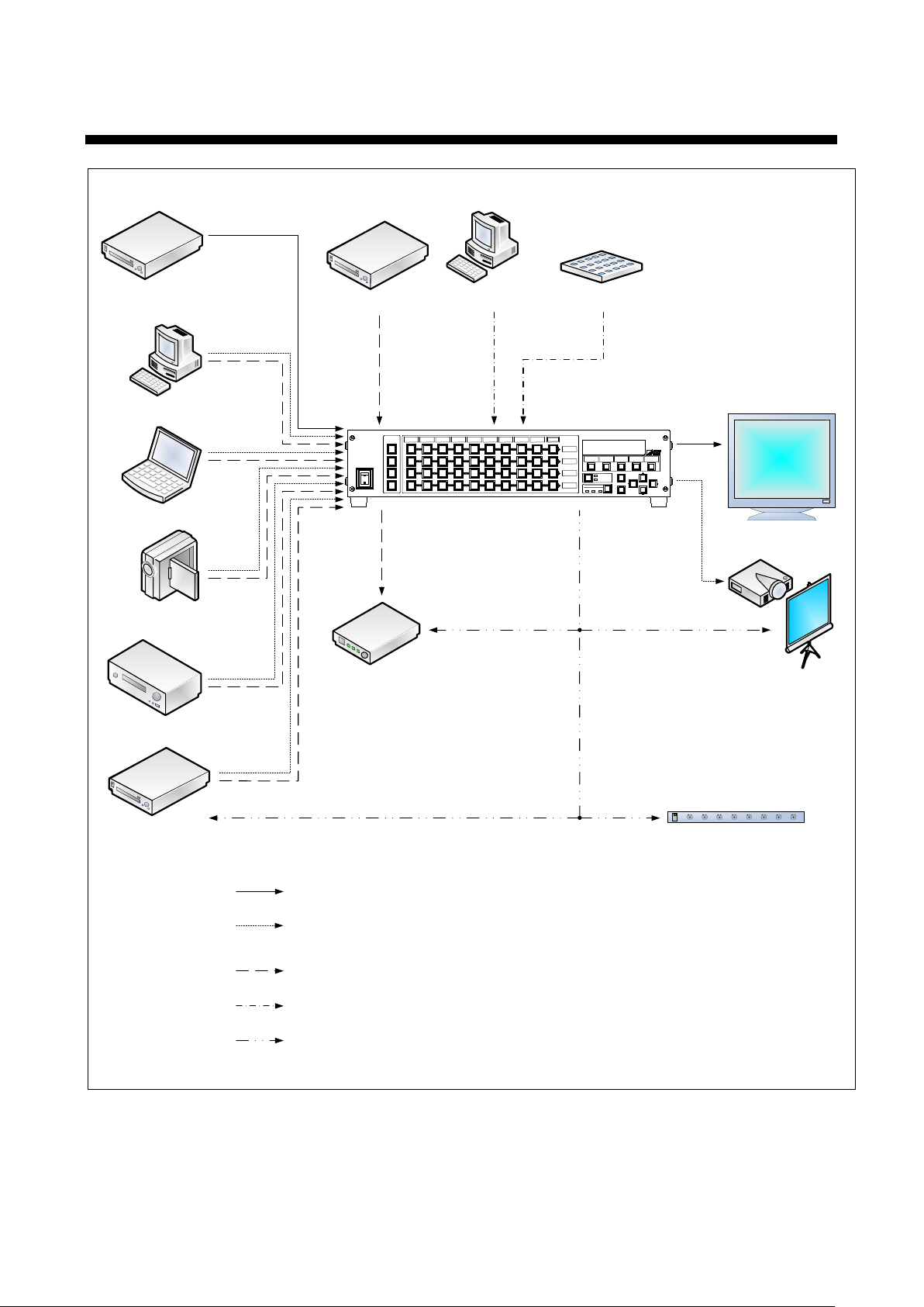
Bru
-ray Player
Desktop Computer
Laptop Computer
Video Camera
DVD Player
Video
/Audio Input
HDMI
DVI
Analog
RGB
Analog
Video
Analog
YPbPr
Video
/Audio
Output
Projector
Monitor
DVI
HDMI
Audio Input
CD Player
External Control
RS
-232
C
LAN
Desktop C
omputer
Control Panel
Parallel
Audio
Outpu
t
Power Amplifier
Controlling peripheral devices
RS
-
232C
LAN
Tally output
CEC
Power Supply Unit
Video/Audio
HDMI
: Embedded audio is available (
Multi-
channel Liner PCM 8ch (7
.1ch
) supported).
Video
Audio
External Control
Controlling peripheral devices
RS-
232C, LAN and Parallel are available.
By registering external control commands, peripheral devices can be controlled via RS-
232C, LAN, Tally
output, or CEC.
PJLink (Class1) is supported.
HDMI,
DVI, Composite (NTSC/
PAL), S-Video
(NTSC/PAL)
, Analog RGB
, Analog YPbPr (SDTV/
HDTV) are
available.
Digital input/output and analog input/
output bidirectional conversion are available.
VHS
S
-Video
POWER
ON
OFF
DIGITAL
MSD
-5404
MULTI
SWITCHER
OUT1
OUT2
OUT3
OUT4
IN1
IN
3
IN
4
IN
5
IN
6
IN
7
IN
8
IN
9
OFF
POWER
DISPLAY
1
2
3
4
IN2
MENU
/SET
ESC
COMMAND
E
COMMAND
COMMAND
COMMAND COMMAND
A
B C D
V&
A
VIDEO AUDIO
SWITCHING MODE
PRESET LOAD
COMMAND
4 System Diagram
[Figure 4.1] Sample configuration
15
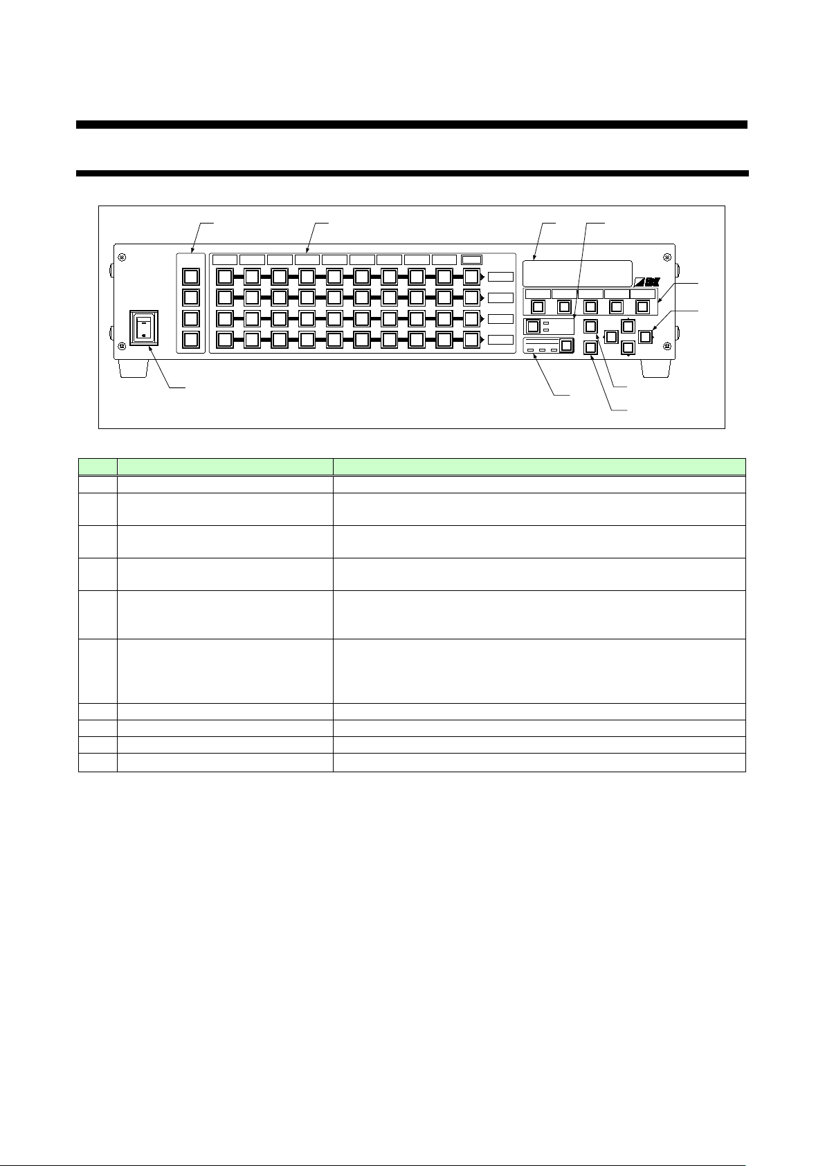
5 Panels
POWER
ON
OFF
DIGITAL
MSD-5404
MULTI
SWITCHER
OUT1
OUT2
OUT3
OUT4
IN1
IN3
IN4 IN
5 IN
6 IN7 IN
8 IN9 OFF
POWER
DISPLAY
1
2
3
4
IN2
MENU/SET
ESC
COMMAND
E
COMMAND COMMAND COMMAND COMMAND
A
B C
D
V&A VIDEO AUDIO
SWITCHING MODE
PRESET LOAD
COMMAND
2 4
1
3
9
8
7
6
5
10
#
Name
Description
1
Power supply switch (POWER)
Turns on/off the MSD.
DISPLAY POWER keys
(DISPLAY POWER 1 to 4)
Turns on/off connected display devices.
Selects switching mode (V&A, VIDEO,AUDIO) if an input is
selected.
Input channel selection keys
(IN1 to IN9, OFF)
Selects video and audio outputs.
Control command execution/
(COMMAND A to E)
Executes registered commands A to E and loads the registered
COMMAND: Executes the registered control command.
or longer. 7 VFD screen
Displays menus and settings.
8
MENU/SET key
Displays menus and edits/controls settings.
9
ESC key
Cancels the current menu setting.
10
Arrow keys (▲, ▼, ◄, ►)
Switches menu, moves cursor, and changes set values.
5.1 Front Panel
MSD-54 SERIES User’s Guide
[Figure 5.1] Front panel
2
3 SWITCHING MODE key
4
5
Cross point loading keys
6 Operation mode selection key
cross point settings.
PRESET LOAD: Loads the registered cross point.
Key lock is enabled/ disabled by pressing this key for 2 seconds
16

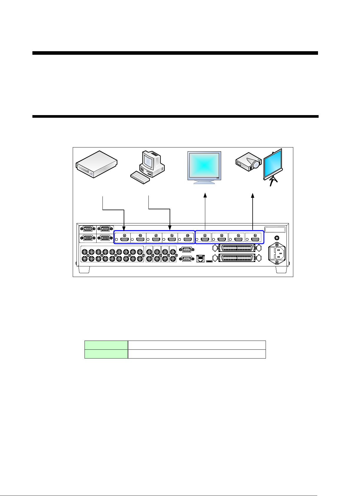
5.2 Rear Panel
HDMI input connectors
DVI signals can be input using an HDMI-DVI
YPbPr (SDTV/HDTV).
HDMI input connector.
connected.
Audio output connectors
Output connectors for stereo audio signals.
web browsers.
8
PARALLEL input port (PARALLEL)
For external control by contacts.
9
Tally output port (TALLY)
For external control by contacts.
Not used.
S/N
FG
HDMI/DVI
OUT 1
OUT 2 OUT 3
OUT 4IN 1
IN 2
IN 3
IN 4 IN 5
ANALOG RGB / YPbPr / VIDEO
ANALOG RGB / YPbPr / VIDEO ANALOG RGB / YPbPr / VIDEO
ANALOG RGB / YPbPr / VIDEO
HDMI/DVIHDMI/DVIHDMI/DVIHDMI/DVIHDMI/DVIHDMI/DVIHDMI/DVIHDMI/DVI
AUDIO AUDIO AUDIO AUDIO
L
R
L
R
L
R
L
R
AUDIO AUDIO AUDIO AUDIO
L
R
L
R
AUDIO AUDIO AUDIO AUDIO AUDIO
L
R
L
R
L
R
L
R
L
R
L
R
L
R
RS-232C CH2
LAN
UPDATE
RS-232C CH1
TALLY
PARALLEL
IN 7 IN 9
IN 8IN 6
IN 1 IN 2 IN 3 IN 4 IN 6 IN 7 IN 8 IN 9 OUT 1 OUT 2 OUT 3 OUT 4IN 5
AC 100-240V 50/60Hz
FUSE
T2.5A 250V
2 1
3
4
5
6
7
8
910
12
11
[Figure 5.1] Rear panel
# Name Description
1
2
(ANALOG RGB/YPbPr/VIDEO IN6 to IN9)
3
4
5
(HDMI/DVI IN1 to IN5) *
Analog video input connectors
Audio input connectors
(AUDIO IN1 to IN9)
HDMI output connectors
(HDMI/DVI OUT1 to OUT4)
(AUDIO OUT1 to OUT4)
6 LAN port (LAN)
7
RS-232C ports
(RS-232C CH1, CH2)
conversion cable.
The following analog video signal formats from
devices can be input: Composite video (NTSC/PAL),
S-video (NTSC/PAL), analog RGB (such as PCs) and
Input connectors for stereo audio signals.
Cannot be used with embedded audio signals of
When a DVI display device is connected, DVI signals
are output autom atically. Built-in cable equalizing
*
circuit enables 5 m/ 16.4 ft. or longer cables to be
For external control by communication commands or
For external control by communication commands
using serial connector.
10 Maintenance port (UPDATE)
11 AC power connector (AC 100 V to 240 V) For the provided power cable.
12 Frame ground (FG) For indoor ground terminal.
*
The HDMI I/O connectors support HDCP (High-bandwidth Di git al Cont ent Pr ot e c tion), whic h is a cop y
protection technique developed by Intel. If DVDs or other contents with copyright protection are played,
both source devices (such as DVD players connected to input connectors) and display devices (connected
to output connectors) are required to be HDCP compliant.
Keep this connector free.
17
MSD-54 SERIES User’s Guide
Bru-
ray Player
Desktop PC
HDMI
Projector
Monitor
HDMI DVI
DVI
S/N
AC90-250V
FG
HDMI/D VI
OUT 1 OUT 2 OUT 3 OUT 4IN 1 IN 2 IN 3 IN 4 IN 5
ANALOG RGB / YPbPr / VIDEO
ANALOG RGB / YPbPr / VIDEO ANALOG RGB / YPbPr / VIDEO
ANALOG RGB / YPbPr / VIDEO
HDMI/D VIHDMI/D VIHDMI/D VIHDMI/D VIHDMI/D VI
HDMI/D VIHDMI/D VIHDMI/D VI
AUDIO AUDIO AU DIO AUDIO
L
R
L
R
L
R
L
R
AUDIO AUDI O AUDIO
AUDIO
L
R
L
R
AUDIO AUDIO AU DIO AUDIO AUD IO
L
R
L
R
L
R
L
R
L
R
L
R
L
R
RS-232C CH2
LAN
UPDATE
RS-232C CH1
TALLY
PARALLEL
IN 7 IN 9
IN 8IN 6
IN 1 IN 2 IN 3 IN 4 IN 6 IN 7 IN 8 IN 9 OUT 1
OUT 2 OUT 3 OUT 4IN 5
Digital input
Up to 10 to 30 meters; approximately 98.43 feet *
Digital output
Up to 10 to 50 meters; approximately 164.04 feet *
6 Installation
Since the MSD has various types of I/O connectors, make sure that shapes of the cables and connectors
match when connecting cables. If you try to connect them forcibly to an unmatched cable and connector, they
might be damaged. If turning on the MSD in that situation, the MSD and display devices may be damaged. Be
sure to plug cables completely and install them without any stress on the cables.
6.1 Cabling Digital I nput/Output Devices
For digital I/O, the HDMI output connectors are employed. The connectors can be connected not only to
HDMI devices but also to DVI devices using HDMI-DVI conversion cables.
For digital I/O, the MSD has the cable equalizing circuit to correct distorted signals when a long cable is
connected. The amount of equalization for the input side is set automatically, but do set the amount for the
output side using the following menu settings: “8.7.1 Output equalizer”.
* Extension distance depends on the connected I/O devices. The range mentioned above is the maximum
extension range acquired when IDK’s AWG24 cable is used and signals of 1080p 60 Hz, 24 bit/pixel
(8bit/component) is input or output. For some I/O combinations, and if you use cables of other manufacturer,
video may be disturbed or may not be output even if signals are within the range mentioned above.
[Figure 6.1] Cabling for digital devices
[Table 6.1] Max. extension range of cable
18

For input and output of HDMI, use HDMI Type A (male) cables.
HDMI cable does not have lock mechanism, but the provided cable clamp prevents the cable from falling off.
[Figure 6.2] Cable clamp
19
MSD-54 SERIES User’s Guide
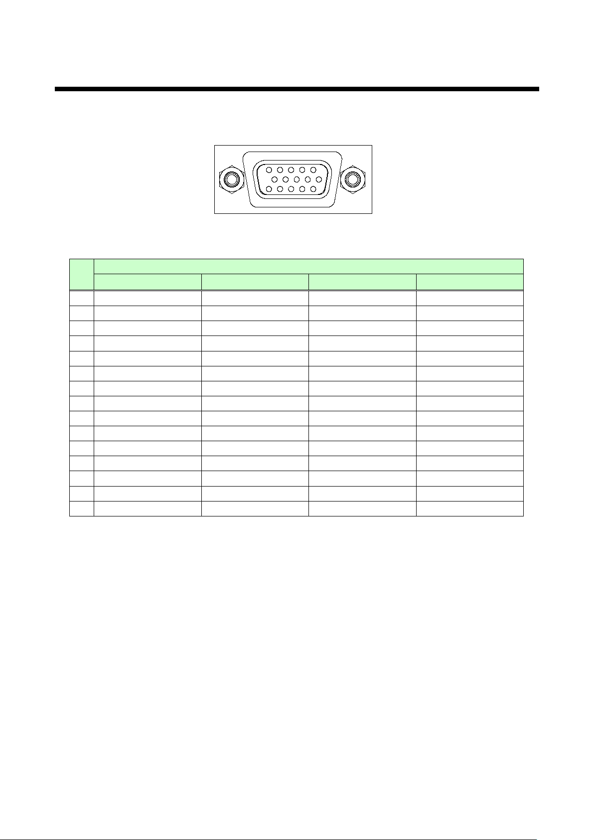
1152345
678910
11121314
Signal
Analog RGB
Analog YPbPr
Composite video
S-video
1
Red
Pr/Cr
N.C.
N.C.
2
Green/G on Sync
Y
VIDEO
Y 3 Blue
Pb/Cb
N.C.
C 4 N.C.
N.C.
N.C.
N.C.
5
GND
N.C.
N.C.
N.C.
6.2 Analog Video Input Connectors
For analog video input, the D-Sub 15 pin connector enables not only analog RGB signals (such as PC) to be
input, but also supports analog YPbPr (SDTV/HDTV), composite video (NTSC/PAL), and S-video
(NTSC/PAL) signal inputs using a conversion cable.
[Figure 6.3] D-Sub15 pin connector
[Table 6.2] Pin assignments
Pin
6 GND GND N.C. N.C.
7 GND GND GND GND
8 GND GND N.C. GND
9 N.C. N.C. N.C. N.C.
10 GND N.C. N.C. N.C.
11 N.C. N.C. N.C. N.C.
12 DDC data N.C. N.C. N.C.
13 HD/CS N.C. N.C. N.C.
14 VD N.C. N.C. N.C.
15 DDC clock N.C. N.C. N.C.
N.C.: No Connection
The type of input video signals is recognized automatically, but if video is not output correctly, select
the signal type manually using the menu shown in section “8.5.4 Signal type of analog input”.
20
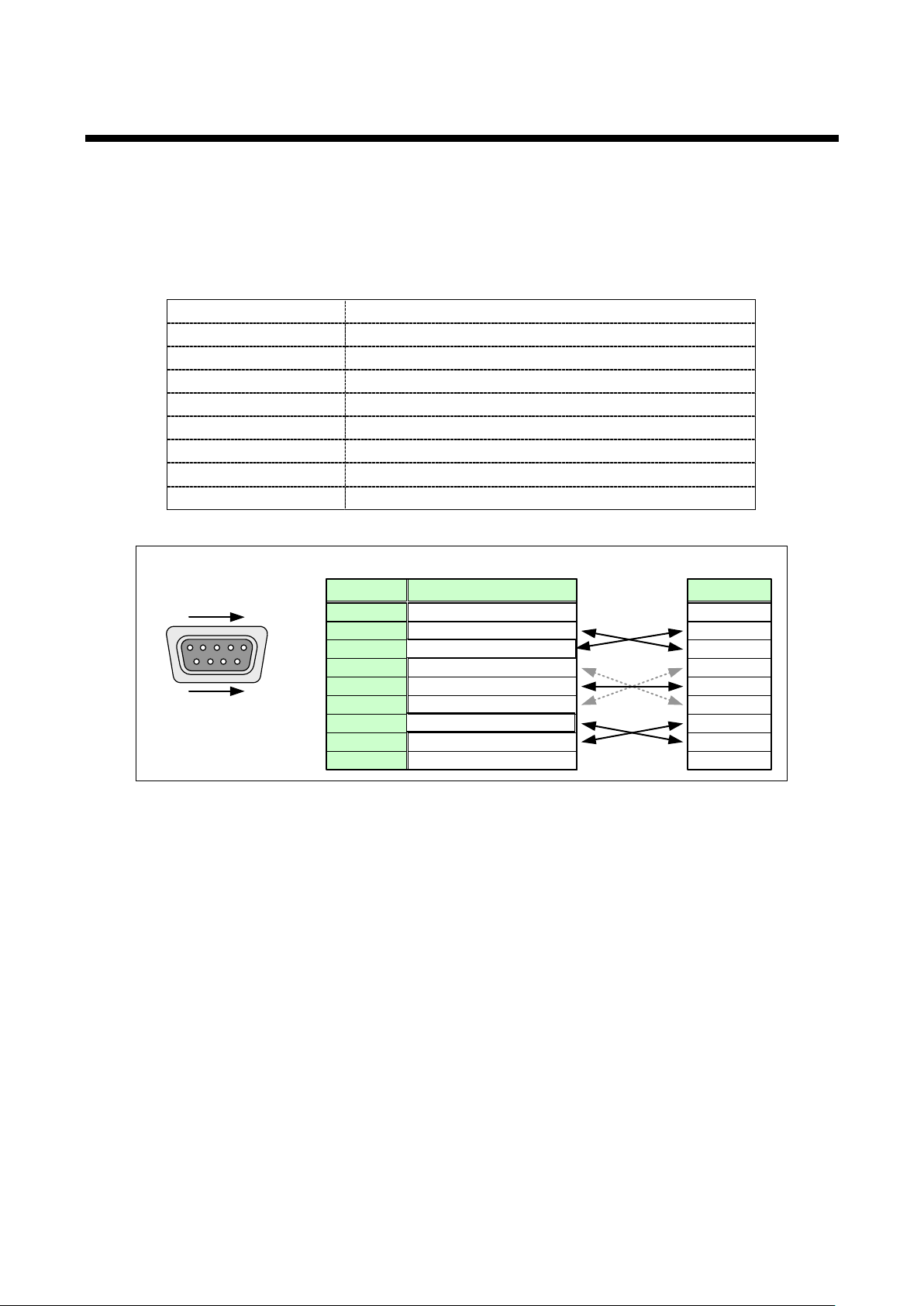
6.3 Serial Port
X parameter
Invalid
Flow control
None
Delimiter
CR LF (Carriage return and line feed, 0D and 0A in hex)
Communication pattern
Full duplex
D-sub
9 pin
(
male)
1
5
RS-232C
connector
6
9
RD: Received Data
TD: Transmitted Data
NC: No connection
NC: No connection
NC: No connection
NC: No connection
GND: Ground
RTS: Request to Send
CTS: Clear to Send
Pin#
1
3
2
4
6
5
7
9
8
Signal
RD
TD
NC
NC
NC
NC
GND
RTS
CTS
Signal
MSD-5404
Cross
cable
Control unit
(MSD-5404 rear panel)
External control via RS-232C is available. The MSD controls peripheral devices externally by serial
communication with RS-232C connector. Connect control devices such as PCs and the MSD with a serial
communication cable, and then control the MSD and acquire status using commands. For character notations
of commands and configuring communication of serial terminal, see sections “9 ASCII codes” and “8.10
Serial (COM) Port Settings”, respectively.
[Table 6.3] Spec of serial communication
Compliance standard RS-232C
Baud rate 4800, 9600, 19200, 38400 [bps]
Data bits 8, 7 [bit]
Parity check None, even, odd
Stop bit 1, 2 [bit]
[Figure 6.4] RS-232C connectors and cables
21
MSD-54 SERIES User’s Guide
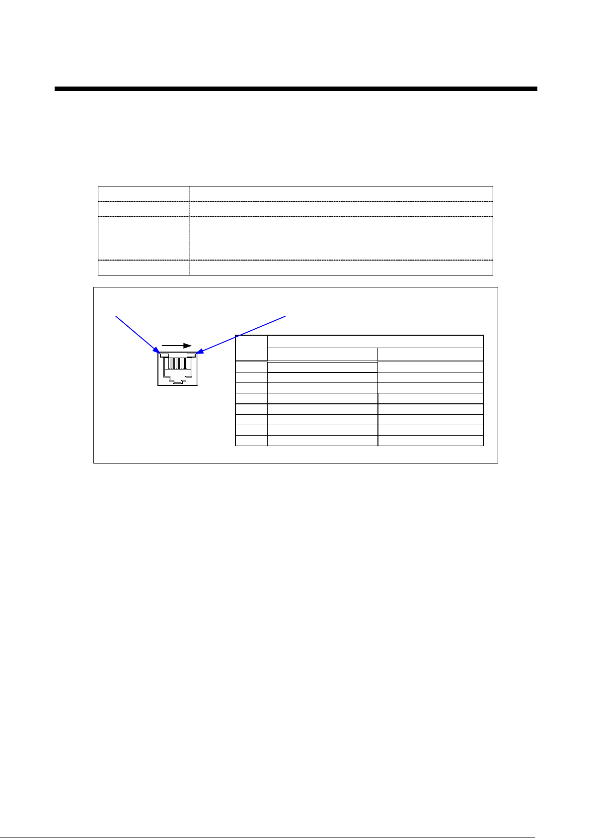
RX+:
Received Data+
NC
: Not connected
TX
+: Transmitted Data+
Pin
#
1
3
2
4
6
5
7
Signal name
TX-
:
Transmitted Data
-
NC:
Not connected
RX-:
Received Data-
NC: Not connected
NC:
Not connected
81
LAN connector
8 pin RJ-
45 connector
(MSD rear panel)
Turns green when a connection between the
MSD and hub or switch is established
.
The orange LED blinks when data is transmitted
or receivd
.
The MSD supports Auto MDI/MDI
-X,
which distinguishes and switches straight/cross cables automatically
.
MDI
TX+:
Transmitted Data+
NC: Not connected
RX
+:
Received Data
+
RX-: Received Data NC:
Not connected
TX
-:
Transmitted Data-
NC: Not connected
NC:
Not connected
MDI
-
X
8
6.4 LAN Port
External control via LAN is available. Use a serial communication cable to connect control devices such as
PCs and the MSD, and then control the MSD and get its status using commands. For character notation of
commands, refer to the “9 ASCII codes”. For control using commands, use ports 6000 to 6999, 1100, and 23.
Connection will be disconnected if no communication for 30 seconds or longer after connection. For setting of
LAN, see section “8.11 LAN Settings”.
[Table 6.4] Spec of LAN communication
Physical la yer 10BASE-T (IEEE802.3i)/100Base-TX (IEEE802.3u)
Network layer ARP, IP, ICMP
TCP
Transport layer
Application layer HTTP, TELNET
Port used for command control: 23, 1100, 6000 to 6999
Port used for WEB browser control (HTTP): 80, 5000 to 5999
[Figure 6.5] LAN connector
22

6.4.1 The number of TCP-IP connections
Your PC software MSD-5404
TCP-IP
connection
→
(1 port is occupied → 7 ports free)
Sending command
(@xxx)
←
Sending reply command (@xxx)
Closing TCP-IP
→
(1 port is released → 8 ports are free)
The MSD can connect up to eight connections (eight ports) simultaneously. If the MSD is controlled from nine
or more PCs, they may not be connected to the MSD.
For nine or more connections, use your software to establish and close TCP-IP connections for each sending
and receiving communication commands. By doing so, connections are occupied and released in the MSD
side so that logically eight or more connections (eight or more ports) can be connected.
→
[Figure 6.6] Increasing connections
Note:
If any command is not sent from the PC side to the MSD for 30 seconds, the MSD disconnects the connection
to avoid the limitation problem on the number of connections. As a result, the connection needs to be
established again from the PC side after the current connection of the PC is disconnected. (Since the number
of ports in the MDS-54 series is eight, if the PC is turned off while it is connected, ports are occupied
permanently. To prevent this, the connection is disconnected if no communication command is sent from the
PC side.)
23

7 Basic Operations
■ Procedure
The LEDs of the selected video/audio inputs illuminate.
AUDIOVIDEOV&A
SWITCHING MODE
7.1 Selecting Input Channels
To select channels for outputting video or audio:
Select the desired mode by the SWITCHING MODE key.
1
Every time you press the key, the mode changes sequentially as follows:
V&A (video & audio simultaneously; set by default)
VIDEO (only video)
AUDIO (only audio)
The LED of the selected mode illuminates.
MSD-54 SERIES User’s Guide
[Figure 7.1] SWITCHING MODE selection key
Press the desired input channel selection key (IN1 to IN9, OFF) to set a channel to output video or
2
audio.
Command control: Switch in g v ideo and audio channel simultaneousl y: @SSW/@GSW
Switching video channel: @SSV/@GSV
Switching audio channel: @SSA/@GSA
24
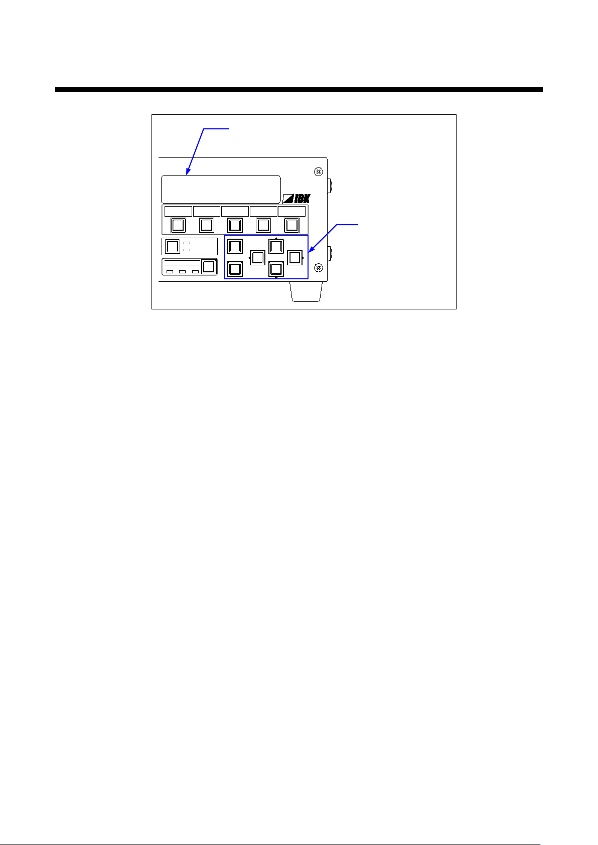
7.2 VFD screen/Menu Operation Keys
MSD-5404
MENU/SET
ESC
COMMANDECOMMAND COMMAND COMMAND COMMAND
A B C D
V&A VIDEO AUDIO
SWITCHING MODE
PRESET LOAD
COMMAND
LCD screen
Menu operation
keys
Use the following keys to set menu options:
[Figure 7.2] Menu operation
MENU/SET key: Displays menus and sets values
“ESC” key: Escapes from menu
▲/▼ Keys: Switches menus and sets values
◄►keys: Moves the cursor and selects the item to be set
VFD screen: Displays menus and settings
See “8.1 Menu List” if necessary.
If no operation is applied for 30 seconds, the brightness of VFD screen is automatically set to 25% level. To
keep the brightness at 100% level at all times, change the Command AUTO LOOK in section “8.18.3
Automatic key lock for control command keys”.
If you need a front panel cover (optional item) to prevent erroneous operations, please contact IDK.
25
MSD-54 SERIES User’s Guide
POWER
ON
OFF
DIGITAL
MULTI
SWITCHER
POWER
DISPLAY
1
2
3
4
Power switches for
display devices
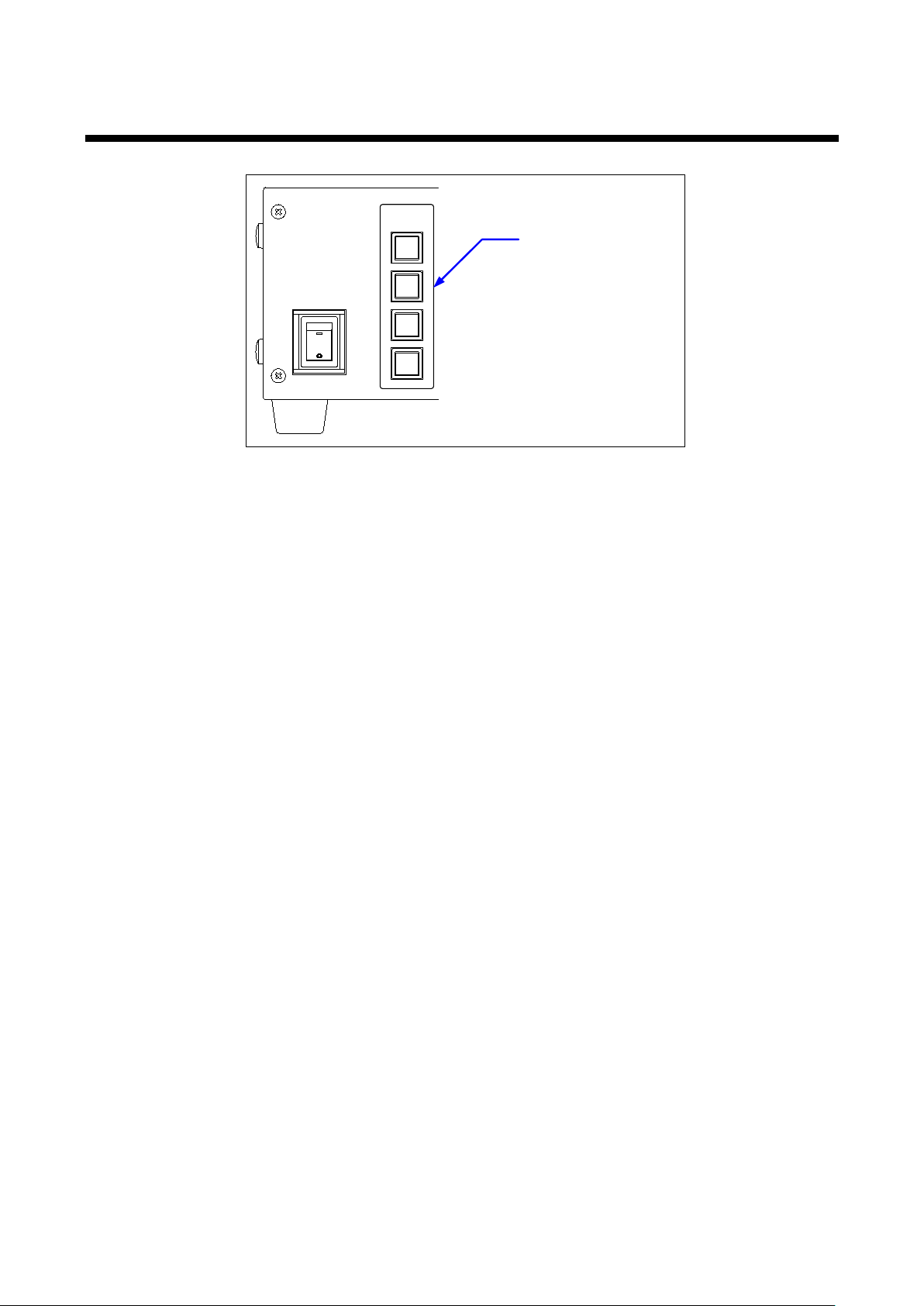
7.3 Turning ON/OFF Display Devices
Use the “DISPLAY POWER” keys to turn on/off the connected display devices:
[Figure 7.3] DISPLAY POWER keys for display devices
Since no values are registered at the factory, in order to use the front panel DISPLAY POWER keys, the
settings for those keys must be first registered into system memory (“8.12.3 Command link”). If you press the
keys accidentally, the display device may be turned off. This can be avoided by pressing and holding the
DISPLAY POWER keys for the registered number of seconds set in “8.18.4 DISPLAY POWER key pressing
time”.
When a command for turning on or off is sent to the display device and the reply command for normal
transmission is received from the display device, the LED of the key turns orange (Power ON) or is turned off
(power OFF). However, if the reply command is not checked, the actual power status of the display device
and LED of DISPLAY POWER key sometimes do not match.
Command control: Setting for display device power switch @SDS /@GDS
26
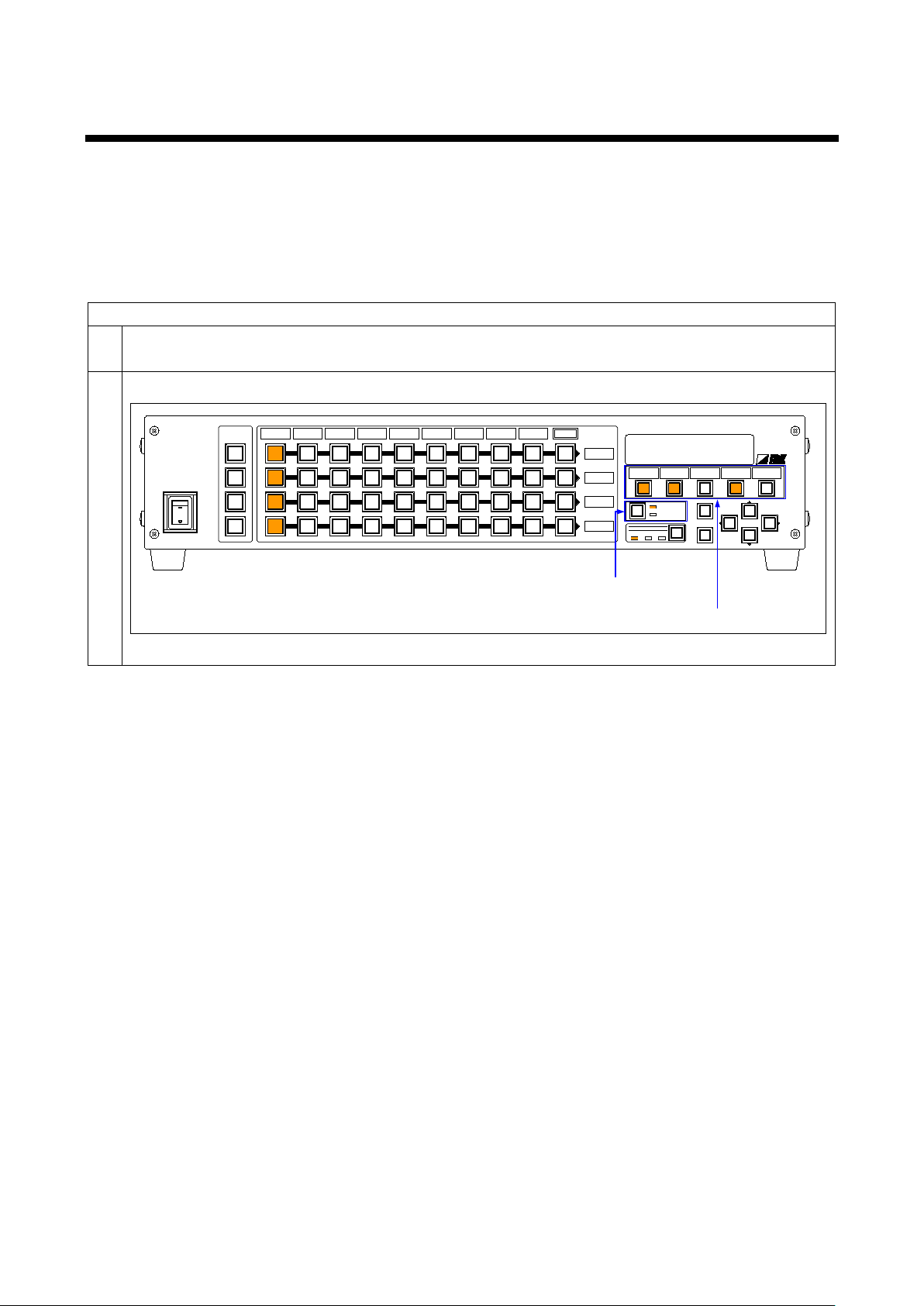
7.4 Executing Control Commands
■ Procedure
Execute the registered command by the control command keys.
POWER
ON
OFF
DIGITAL
MSD-5404
MULTI
SWITCHER
OUT1
OUT2
OUT3
OUT4
IN1
IN3
IN4
IN5
IN6 IN7 IN8
IN9
OFF
POWER
DISPLAY
1
2
3
4
IN2
MENU/SET
ESC
COMMANDECOMMAND COMMAND COMMAND COMMAND
A B C D
V&A VIDEO AUDIO
SWITCHING MODE
PRESET LOAD
COMMAND
Control command keys
Operation mode key
[Figure 7.4] Keys for command execution
You can register up to nine control commands in MSD (COMMANDs A to I), but you can execute only five
commands (COMMANDs A to E) with control front panel command execution keys. To execute COMMANDs
F to I, perform “8.12.4 Command execution” or use RS-232C, LAN, or parallel input.
For COMMANDs A to I, nothing is registered by the factory default, so those keys will not work until their
commands are registered in “8.12.3 Command link”.
Command control: Controlling command execution: @EXC
To execute commands associated with Control Command execution keys (COMMANDs A to E):
Select ”COMMAND” by the operation mode key.
1
2
27
MSD-54 SERIES User’s Guide
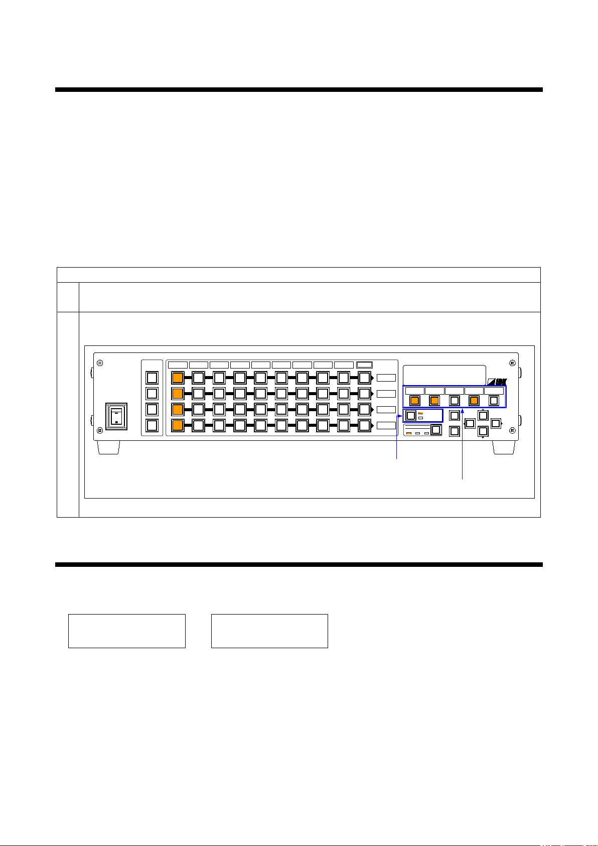
■ Procedure
Press the cross point command keys to load the cross point settings.
POWER
ON
OFF
DIGITAL
MSD-5404
MULTI
SWITCHER
OUT1
OUT2
OUT3
OUT4
IN1
IN3 IN4
IN5 IN6
IN7 IN8 IN9 OFF
POWER
DISPLAY
1
2
3
4
IN2
MENU/SET
ESC
COMMANDECOMMAND COMMAND COMMAND COMMAND
A B C D
V&A VIDEO AUDIO
SWITCHING MODE
PRESET LOAD
COMMAND
Cross point load key
Operation mode
selection keys
[Figure 7.5] Loading cross points
KEY LOCK ! KEY LOCK RELEASE !
7.5 Loading Cross Point
You can register up to nine cross points in the MSD, but the MSD c an onl y load cross points 1 to 5 b y cross
point load ke ys. To load c ross points 6 to 9, use m enu settings in the “Load c ross point” section (“8.13.1
Loading cross point”) or use RS-232C, LAN, or parallel inputs.
Since nothing is registered by factory default, cross point is not valid until they are registered. To load them,
register cross points in advance.
Command control:
▪ Loading V&A input selection setting from cross point memory: @RCM
▪ Loading video input selection setting from cross point memory: @RCV
▪ Loading audio input selection setting from cross point memory: @RCA
To load cross point settings:
Select ”PRESET LOAD” using the Operation Mode selection key.
1
2
Commands A to E correspond to cross points 1 to 5.
7.6 Locking/Unlocking Front Keys
To lock the front panel keys, press and hold the Operation Mode selection key for 2 seconds or longer until
hearing the buzzer sound. To release the key lock, do the same operation again. When the setting is changed,
the status will be displayed for 1 second.
Locked Unlocked
Command control: Setting and releasing key lock: @SLS/@GLS
28
7.7 WEB Browser Control
1
2
4
6
7
3
8
9
10
11
5
1
2
3
4
5 6
7
8
9
10
11
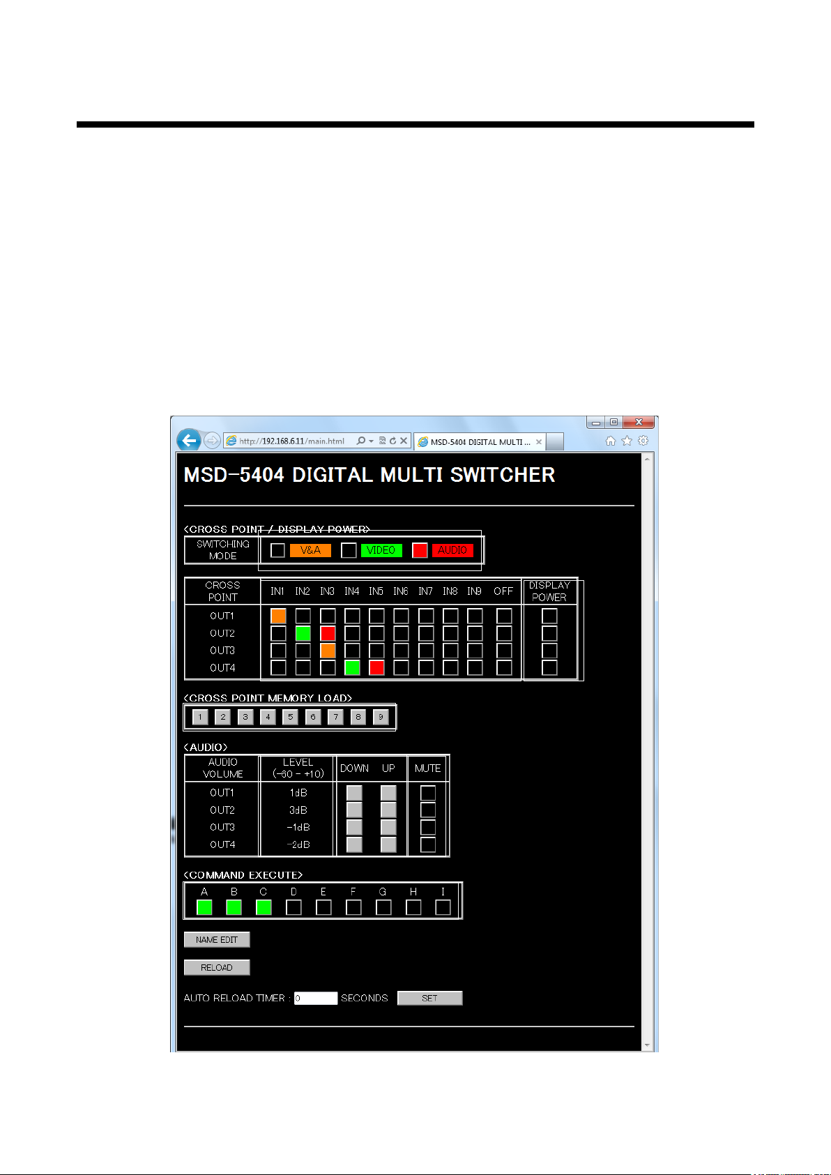
The MSD-54 connected through LAN can be controlled from a WEB browser such as Microsoft Internet
Explorer.
To open the operation window, open a WEB browser in the PC through the same LAN network and enter the
MSD’s IP address into the address bar. For LAN settings, see “8.11 LAN Settings”.
Note:
We tested the MSD using Microsoft Internet Explorer 6.0, 7.0 and 8.0 for Windows. The MSD may possibly
operate incorrectly on other versions and/or browsers.
If the port number of the browser control port is set to 80 (normal setting):
Use the following format: http://192.168.1.199
If the port number of the browser control port is set to a number other than 80 (5000 to 5999):
(Example: No. 5000)
Use the following format: http://192.168.1.199:5000
[Figure 7.6] WEB browser control window
29

8.12.3 Command link
MUTE
Red: MUTE ON; Black: MUTE OFF
Executes control commands assigned to COMMAND A to I. No command
EXECUTE”. Click this button, to open the window of [Figure 7.7].
Number
Item Description
Sets and displays channel switching mode. Does not affect switching
1
SWITCHING
MODE
mode of the front panel and parallel input.
V&A (switching video & audio simultaneously), VIDEO (switching only
video), AUDIO (switching only audio)
2
Input channel
selection (IN1 to
Selects video and audio output.
Orange: Video & Audio; Green: Only Video; Red: Only audio
IN9, OFF )
Turns on/off connected display devices. No command is registered by
3 DISPLAY POWER
factory default. To operate display’s power, register the command to this
switch in “
4 Cross point Loads registered cross point.
5 Audio output level Displays the current audio output level.
6
7
Audio output level:
UP, DOWN
Audio output level:
Turns up/down the volume 1 [dB] per click.
Turns on and off the mute function.
MSD-54 SERIES User’s Guide
”.
8
COMMAND
EXECUTE
9 NAME EDIT
10 RELOAD
11
AUTO RELOAD
TIMER
is registered by factory as default. To execute control commands, register
them to COMMAND A to I in advance by following instructions in section
8.12.3 Command link”.
“
Buttons in which control command is registered are displayed in green.
However, as each command (A to I) has two planes (PLANE A and B), two
commands are executed alternately if two different commands are
registered to plane A and B. If PLANE B is executed, the button is
displayed in green (PLANE A will be executed at the next click); if PLANE
A is executed, the button displayed in orange (PLANE B will be executed at
the next click).
Edits names of “CROSS POINT”, “AUDIO VOLUME,” and ”COMMAND
Acquires the latest information of the MSD from the MSD. (It can also be
updated automatically by setting “AUTO RELOAD TIMER”, 11, below.)
Sets time interval to receive the latest information periodically and to
refresh WEB browser window. You can set the interval from 10 to 65535
seconds by 1 second. If you do not use this function, set the interval to 0
second (factory default).
30
 Loading...