

Page 1
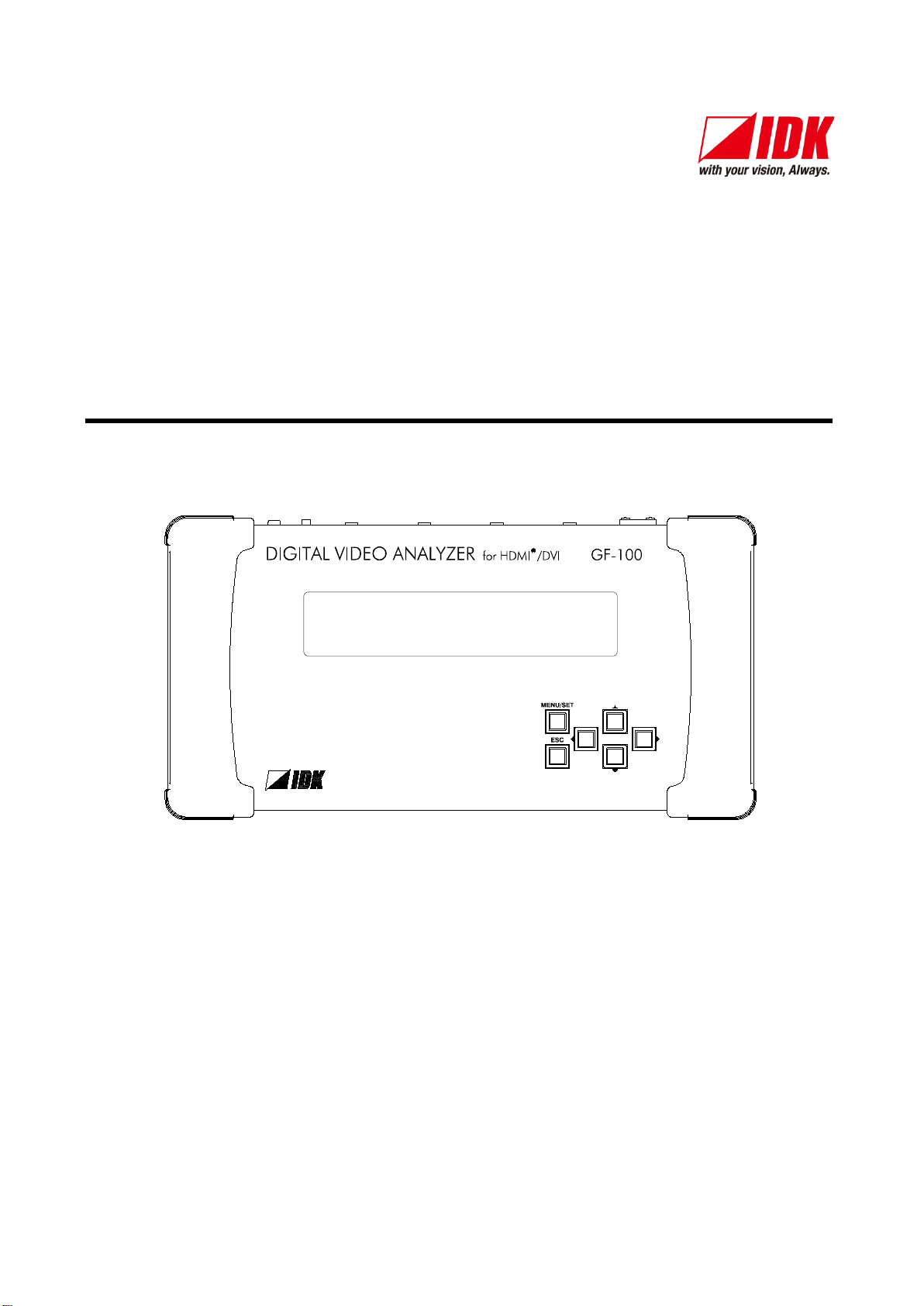
Digital Video Analyzer
GF-100
User’s Guide Ver.1.0.0
● Thank you for choosing this IDK product.
● To ensure the best performance of this product, please read this User’s Guide fully and carefully before
using it and store this manual near this product.
IDK Corporation
Page 2

GF-100 User’s Guide
Trademarks
The terms HDMI and HDMI High-Definition Multimedia Interface, and the HDMI Logo are trademarks or
registered trademarks of HDMI Licensing, LLC in the United States and other countries.
All other company and product names mentioned in this manual are either registered trademarks or
trademarks of their respective owners. In this manual, the “®” or “™” marks may not be specified.
2
Page 3

GF-100 User’s Guide
Before reading this manual
● All rights reserved.
● Some of the contents in this User’s Guide such as appearance diagrams, menu operations,
communication commands, and so on may differ depending on the version of the extender.
● This User’s Guide is subject to change without notice. You can download the latest version from IDK’s
website at: http://www.idk.co.jp/en/index.html
FCC STATEMENT
This equipment has been tested and found to comply with the limits for a Class A digital device, pursuant to
part 15 of the FCC Rules. These limits are designed to provide reasonable protection against harmful
interference when the equipment is operated in a commercial environment. This equipment generates, uses,
and can radiate radio frequency energy and, if not installed and used in accordance with the instruction
manual, may cause harmful interference to radio communications. Operation of this equipment in a residential
area is likely to cause harmful interference. The user will be required to correct that interference at their own
expense.
CE MARKING
This equipment complies with the essential requirements of the relevant European health, safety and
environmental protection legislation.
WEEE MARKING
Waste Electrical and Electronic Equipment (WEEE), Directive 2002/96/EC
(This directive is only valid in the EU.)
This equipment complies with the WEEE Directive (2002/96/EC) marking requirement.
The left marking indicates that you must not discard this electrical/electronic equipment in
domestic household waste.
3
Page 4
GF-100 User’s Guide
Enforcement Symbol
Description
Symbol
Description
Example
Hazard
disassemble
Caution
Warning
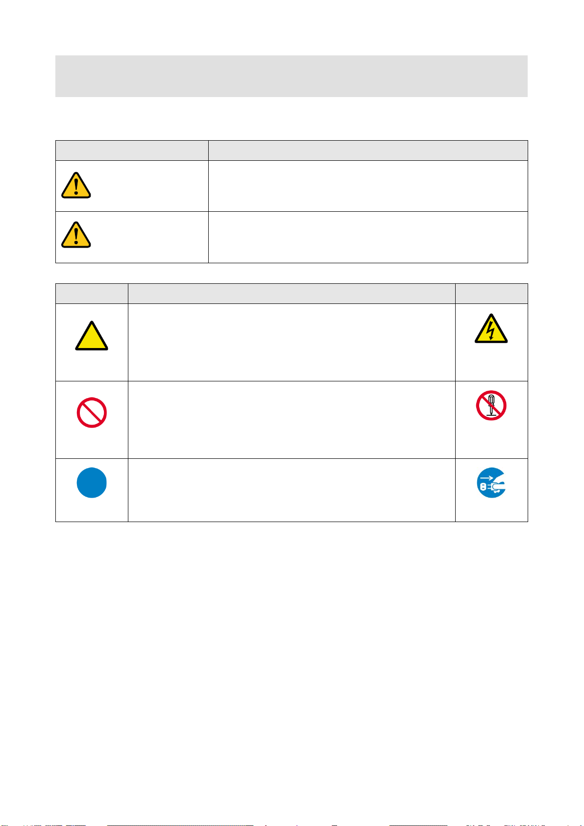
Safety instructions
Read and understand all safety and operating instructions before using this product. Follow all instructions
and
cautions as detailed in this document.
Indicates the presence of a hazard that may result in death or serious
personal injury if the warning is ignored or the equipment is handled
incorrectly.
Caution
Prohibition
Instruction
Indicates the presence of a hazard that may cause minor personal
This symbol is indicated to alert the user. (Warning and caution)
This symbol is intended to prohibit the user from actions.
This symbol is intended to instruct the user.
injury or property damage if the caution is ignored or the equipment is
handled incorrectly.
Electrical
Do not
Unplug
4
Page 5
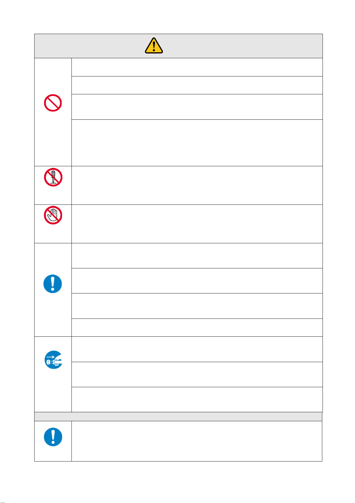
Do not place the product in any unstable place.
Install the product to a horizontal and stable place. Otherwise, it may fall/turn over and lead to injury.
Do not place the product in any environment with vibration.
Otherwise, it may move/fall and lead to injury.
Keep out any foreign objects.
the vent holes.
For power cable/ plug:
damaged, contact IDK.
Do not repair, modify or disassemble.
touch
In the event of lighting or thunder, do not touc h the main u nit and cables such as power
For installation:
IDK. Otherwise, it may cause fire, electric shock, injury, or property damage.
Set the power plug in a convenient place to unplug easily.
you do not use it for a long period.
Plug the power plug into appropria te outlet completely.
loosened outlet.
Clean the power plug regularly.
If the plug is covered in dust, it may cause fire due to reduced insulating power.
Unplug immediately if the product smokes, makes unusual noise, or smells.
product stops smoking, contact IDK.
Unplug immediately if you drop the product or if the cabinet is damaged.
repair, contact IDK.
Unplug immediately if water or other objects are directed inside.
contact IDK.
For connection
Warning
Prohibition
Do not
disassemble
GF-100 User’s Guide
In order to avoid fire or electric shock, do not allow foreign objects, such as metal and paper, to enter the product from
・Do not scratch, heat, or modify, including extending them.
・Do not pull, put heavy stuff on them, or pinch them.
・Do not bend, twist, or tie them together forcefully.
If they are used in those states continuously, it may cause fire or electric shock. If power cables/plugs become
Since the product includes high-voltage parts, those actions may cause fire or electric shock. For internal inspections
or repairs, contact IDK.
Do not
Instruction
Unplug
cable and LAN cable.
Contact may cause electric shock
The product is intended to be installed by skilled technicians. For installation, please contact a system integrator or
You can easily unplug in case of any extraordinary failure or abnormal situation, and it also helps for unplugging w hen
If the plug is plugged incompletely, it may overheat which causes electrical shock or fire. Do not use damaged plug or
If you continue to use the product under those situations, it may cause electric shock or fire. After confirming that the
If you continue to use the product under those situations, it may cause electrical shock or fire. For maintenance and
If you continue to use it under those situations, it may cause electrical shock or fire. For maintenance and repair,
Differences in ground potential among the product and peripheral devices may cause electric shock or damage of
Instruction
the devices. When using cables to connect devices, including connection of long-distance transmission, unplug the
power cables of all related devices.
After connecting signals/control cables of each device, plug in the power cables of each device.
5
Page 6
GF-100 User’s Guide
For installation
Instruction
Never insert only the screws into the holes after removing the rubber feet. It may lead to
Do not place the product in humid, oil smoke, or dusty place.
Do not put heavy items on the product.
Caution
Prohibition
No wet
hands
Instruction
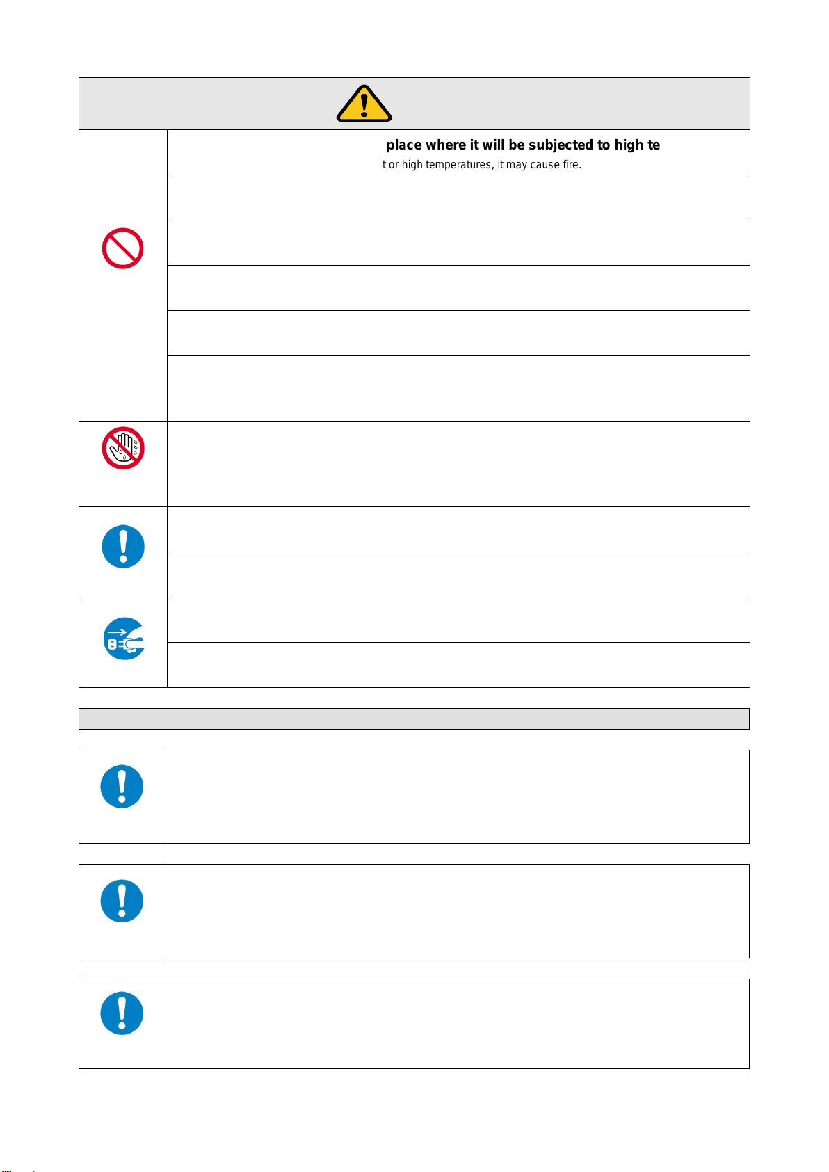
Do not place the product in any place where it will be sub jected to high temperatures.
If the product is subjected to direct sunlight or high temperatures, it may cause fire.
If the product is placed near humidifiers or dusty area, it may cause fire or electric shock.
Do not block the vent holes.
If ventilation slots are blocked, it may cause fire or failure due to internal heat.
It may fall/turn over and lead to injury.
Do not exceed ratings of outlet and wiring devices.
If several plugs are put in an outlet, it may cause fire and electric shock.
Use only the provided AC adapter and power cabl e.
If non-compliant adapter or power cables is used, it may cause fire or electrical shock. Use the provided AC power
connection cable. If you want to use your product in other countries that use different AC power cables, contact IDK.
Do not plug or unplug with wet hands.
It may cause electrical shock.
Use and store the product within the specified temperature/humidity range.
If the product is used outside the range continuously, it may cause fire or electric shock.
Turn off devices when they are connected to another device.
It may cause fire or electric shock.
Unplug
Unplug the power plug if you do not use the product for a long period.
In case of defect, it may cause fire.
Unplug the power plug before cleaning.
It may cause electric shock.
For rack mount devices:
Mount the product to the rack meeting EIA standards, and maintain spaces above and below
for air cooling. For your safety, attach an L-shape bracket in addition to the mount bracket kit
for the front panel to balance the weight.
For devices with rubber feet:
damage when the screws contact electrical circuit or parts inside of the product.
To put the rubber feet back on, use only provided rubber feet and screws.
Instruction
Altitude:
Do not place the product at elevations of 2,000 meters (6562 feet) or higher above sea level.
Failure to do so may shorten the life of the internal parts and result in malfunctions.
Instruction
6
Page 7

GF-100 User’s Guide
Table of Co ntents
1 Included items ............................................................................................................................................ 9
2 About the GF-100 ..................................................................................................................................... 10
3 Example of use ......................................................................................................................................... 12
3.1 Application example ......................................................................................................................... 12
3.2 Sink test ............................................................................................................................................ 12
3.3 Source test ....................................................................................................................................... 13
3.4 Repeating source and sink tests ...................................................................................................... 14
3.5 Test from source device ................................................................................................................... 15
4 Top and rear panel ................................................................................................................................... 16
5 Basic operation ......................................................................................................................................... 17
5.1 Menu operation ................................................................................................................................. 17
5.2 Setting/canceling key lock ................................................................................................................ 18
5.3 Initialization ....................................................................................................................................... 18
6 Source test ............................................................................................................................................... 19
6.1 Displaying source status................................................................................................................... 19
6.2 Displaying source status (example) ................................................................................................. 21
6.2.1 Detecting source signals ........................................................................................................... 21
6.2.2 Video timing (Resolution/scanning method/frame rate/aspect ratio) ........................................ 21
6.2.3 HDMI/DVI (with/without audio) .................................................................................................. 22
6.2.4 With/without HDCP (copyright protection) ................................................................................ 23
6.2.5 Color space ............................................................................................................................... 23
6.2.6 Color depth (Deep Color) .......................................................................................................... 24
6.2.7 Audio format .............................................................................................................................. 25
6.2.8 Speaker configuration ............................................................................................................... 25
6.3 History of source status .................................................................................................................... 26
6.3.1 Beep for source status change ................................................................................................. 28
6.3.2 Escape sequence of source status ........................................................................................... 28
6.3.3 Wait time for detecting source status ........................................................................................ 28
6.4 EDID emulator .................................................................................................................................. 29
6.4.1 Outline ....................................................................................................................................... 29
6.4.2 EDID output mode .................................................................................................................... 30
6.4.3 Saving EDID ............................................................................................................................. 30
6.4.4 Resolution of original GF-100 EDID ......................................................................................... 31
6.4.5 Color depth of original GF-100 EDID ........................................................................................ 31
6.4.6 Number of audio channels of original GF-100 EDID ................................................................ 32
6.4.7 Audio format of original GF-100 EDID ...................................................................................... 33
7 Sink test .................................................................................................................................................... 34
7.1 Sink status ........................................................................................................................................ 34
7.2 Displaying sink status ....................................................................................................................... 35
7.2.1 Detecting sink device ................................................................................................................ 35
7.2.2 HDMI (Audio) supported/not supported .................................................................................... 35
7.2.3 HDCP (copyright protection) supported/not supported ............................................................. 36
7.2.4 Supported color space .............................................................................................................. 36
7.2.5 Supported color depth (Deep Color) ......................................................................................... 37
7.2.6 Preferred/native resolution ........................................................................................................ 38
7.2.7 Configuration of supported speakers ........................................................................................ 38
7.2.8 Detailed EDID inform ation ........................................................................................................ 39
7
Page 8

GF-100 User’s Guide
Test pattern/tone .............................................................................................................................. 39
7.3
7.3.1 Outputting test pattern/tone ...................................................................................................... 39
7.3.2 Selecting test pattern ................................................................................................................ 40
7.3.3 Test pattern resolution .............................................................................................................. 41
7.3.4 Test pattern HDCP .................................................................................................................... 42
7.3.5 Test pattern format/color space ................................................................................................ 42
7.3.6 Test pattern color depth ............................................................................................................ 42
7.3.7 Selecting test tone .................................................................................................................... 43
7.3.8 Test tone: output channel ......................................................................................................... 43
7.3.9 Test tone: standard level .......................................................................................................... 44
8 Monitoring DDC ........................................................................................................................................ 45
8.1 Outline .............................................................................................................................................. 45
8.2 Recording item ................................................................................................................................. 47
8.3 Beep sound ...................................................................................................................................... 47
8.4 DDC Escape sequence .................................................................................................................... 47
9 Cable /transmission path test ................................................................................................................... 48
9.1 Outline .............................................................................................................................................. 48
9.2 Operation and display example ........................................................................................................ 50
9.3 Test signals resolution ...................................................................................................................... 53
9.4 The amount of test data.................................................................................................................... 53
9.5 Test signals color depth.................................................................................................................... 53
9.6 Waiting time for starting pixel scan ................................................................................................... 54
9.7 Starting measurement ...................................................................................................................... 54
10 Setting GF-100 ..................................................................................................................................... 55
10.1 Source test connector....................................................................................................................... 55
10.1.1 Requesting input signals ........................................................................................................... 55
10.1.2 Input DC balance ...................................................................................................................... 55
10.1.3 HDCP enabled/dis ab le d ........................................................................................................... 55
10.1.4 Input bus reset time .................................................................................................................. 56
10.2 Sink test connector ........................................................................................................................... 56
10.2.1 Outputting signals forcibly ......................................................................................................... 56
10.3 System Clock .................................................................................................................................... 56
10.3.1 Setting current time of the GF-100 ........................................................................................... 56
10.4 LAN ................................................................................................................................................... 57
10.4.1 IP address ................................................................................................................................. 57
10.4.2 Default gatewa y ........................................................................................................................ 57
10.4.3 Subnet mask ............................................................................................................................. 57
10.4.4 Displaying MAC address........................................................................................................... 57
10.5 Others ............................................................................................................................................... 58
10.5.1 Time for turning off backlight .................................................................................................... 58
10.5.2 Beep sound ............................................................................................................................... 58
10.5.3 Resume ..................................................................................................................................... 58
10.5.4 Versions .................................................................................................................................... 58
11 Setting list ............................................................................................................................................. 59
12 Product specification ............................................................................................................................ 61
8
Page 9
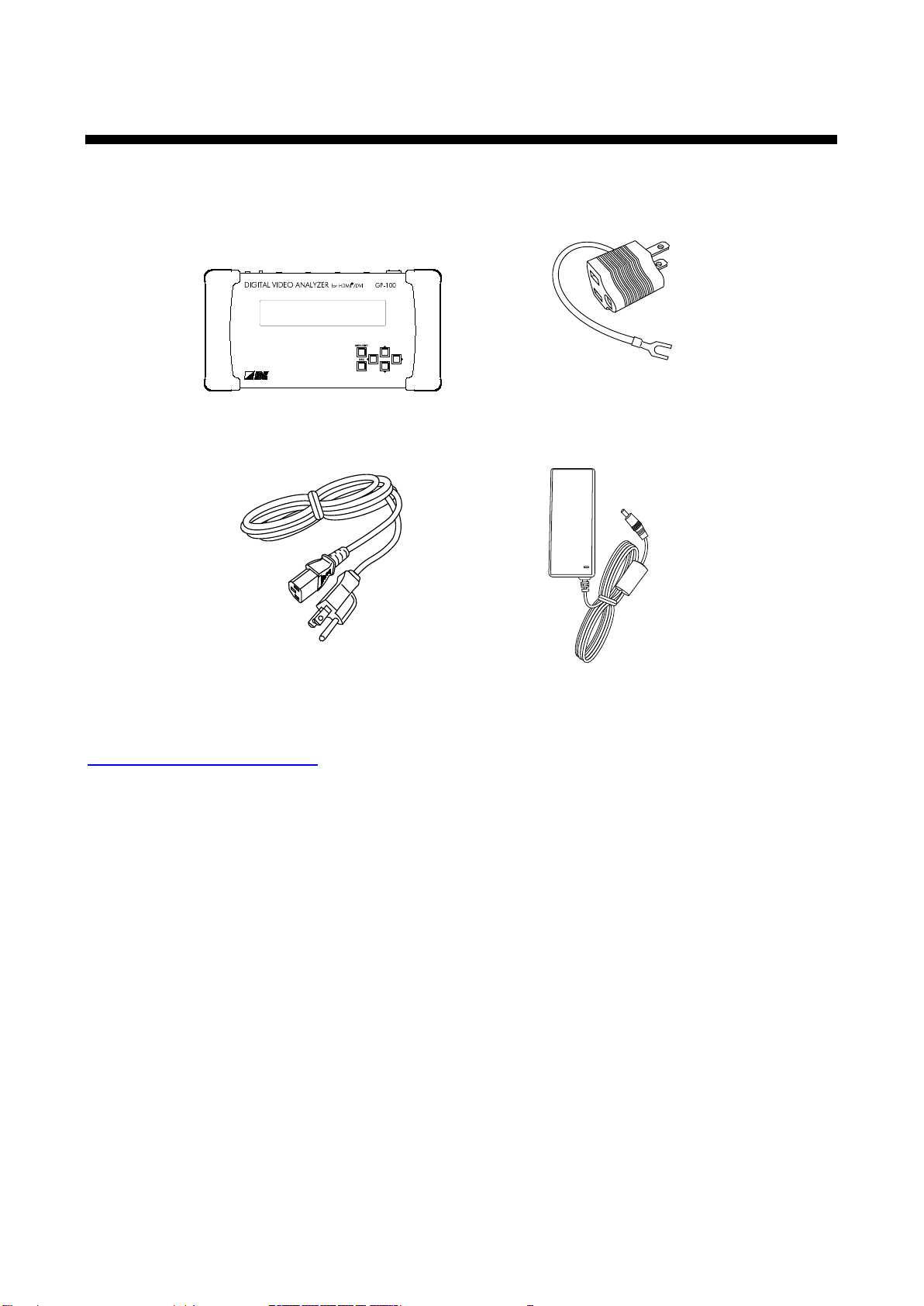
1 Included items
Make sure all items below are included in the package.
If any items are missing or damaged, please contact IDK.
GF-100 x 1
Power cable (1.8m/5.9 feet) x1
[Fig. 1.1] Included items
GF-100 User’s Guide
2P-3P conversion plug x 1
AC adapter (1.8m/5.9 feet) x1
You can download the latest version of the User’s Guide from IDK’s website at:
http://www.idk.co.jp/en/index.html
9
Page 10
GF-100 User’s Guide
HDMI/
DVI
Source device
TO SOURCE
Source test
Displaying sink EDID
EDID emulator
(with copy function
)
Test pattern/
Test tone generator
HDMI
/DVI
Sink device
TO SINK
HDMI
/DVI
Source
/Sink device
HDMI
/
DVI
Sink
/Source device
DDC A DDC B
DDC monitor
Sink test
GF-
100
Source device
GF-100
Sink device
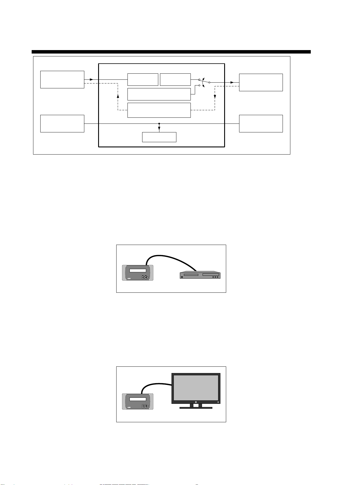
2 About the GF-100
[Fig. 2.1] Diagram
The IDK’s GF-100 is a portable digital video checker for HDMI/DVI devices, providing source/sink tests,
cable/transmission line tests, and monitoring DDC function between source and sink devices.
■ Source test (P.19)
● Displays the following statuses on the LCD display or browser: resolution, frequency, presence or
absence of audio, status of DDC voltage, and the like.
● Outputs status changes to a browser or ICT/IP port “2200”.
● Has an EDID emulator (P.29).
[Fig. 2.2] Source test
■ Sink test (P.34)
● Displays the following items on the LCD display or browser: supported resolution, audio supported/not
supported, HDCP compliant/not compliant, EDID, and other information.
● Outputs test patterns (video)/test tone (audio). (P.39)
● Saves up to five EDIDs of the sink device in the GF-100.
● Downloads the saved EDIDs onto the PC via the browser; they can be read with analysis software.
[Fig. 2.3] Sink test
10
Page 11
GF-100 User’s Guide
GF-100Sink device
Source
device
Cable
GF-100
Transmission
path
GF-100 GF-100
Test signal
Test signal
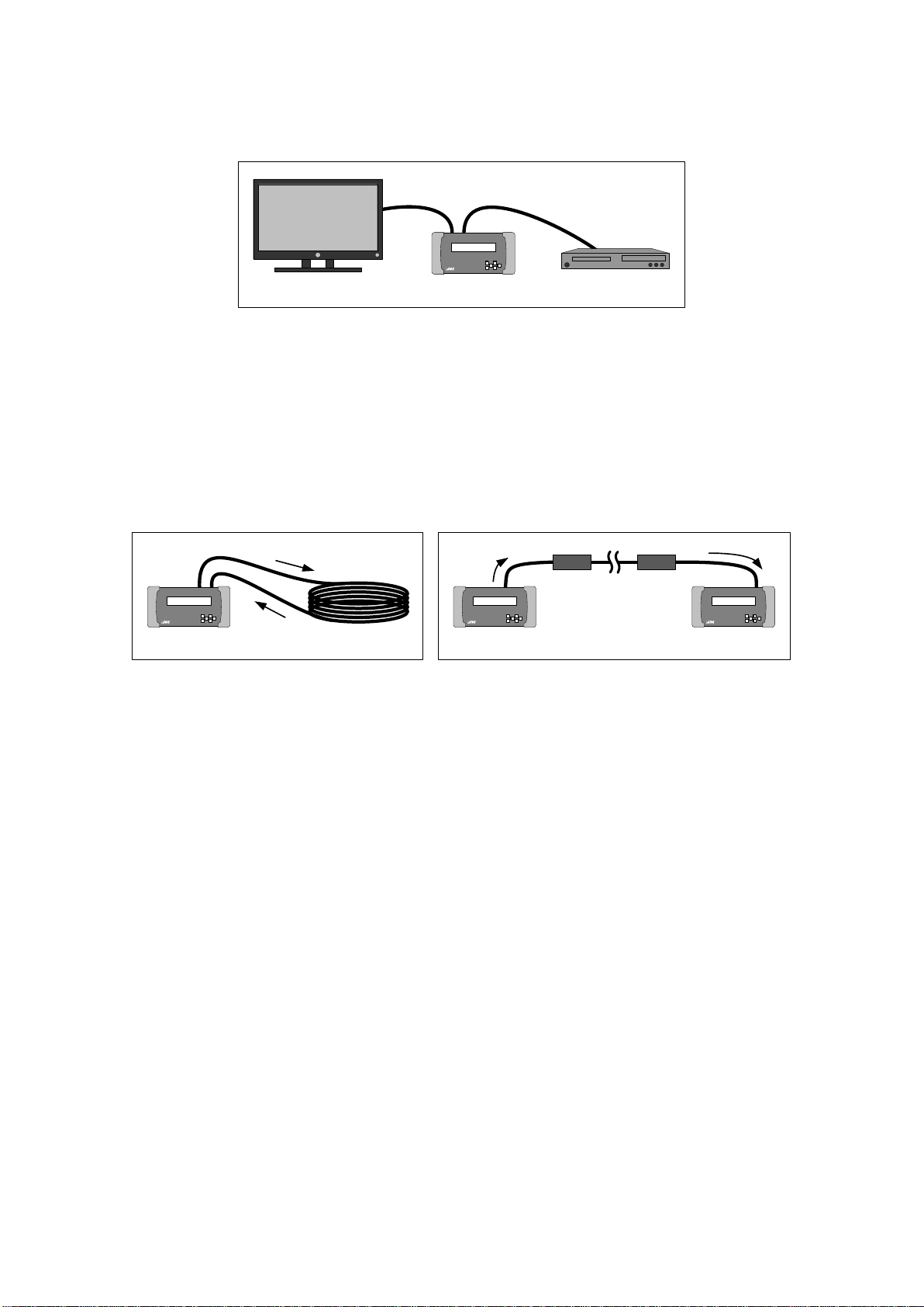
■ DDC monitor (P.45)
● Outputs the DDC communication data of the source and sink devices to browser or the TCP/IP port
“1100”.
[Fig. 2.4] DDC monitor
■ Cable/transmission path test (P.48)
● Outputs the test signals and measures the quality (bit color) of the cable/transmission path.
● The test signals consist of random data and data that is under tougher condition (the hardware of the
cable and its transmission).
● The resolution and color depth of the test signals can be selected.
● With two GF-100 devices, the transmission path test between two distant sites can be performed.
[Fig. 2.5] Cable test [Fig. 2.6] Transmission path test
■ Additional function
● Resume function (P.58)
Note: The GF-100 is a simplified analyzer for field supports of AV systems. Please note that it does not
provide calibrations.
11
Page 12
GF-100 User’s Guide
BD playerMonitor
Distribution
amplifier
Switcher
Cable 3Cable 2
Video is not displayed
Cable 1
Audio is not output
EDID
1
Copy
EDID
3
EDID
2
Sink device
GF-100
Cable 1
BD playerMonitor
Distribution
amplifier
Switcher Cable 3Cable 2
①
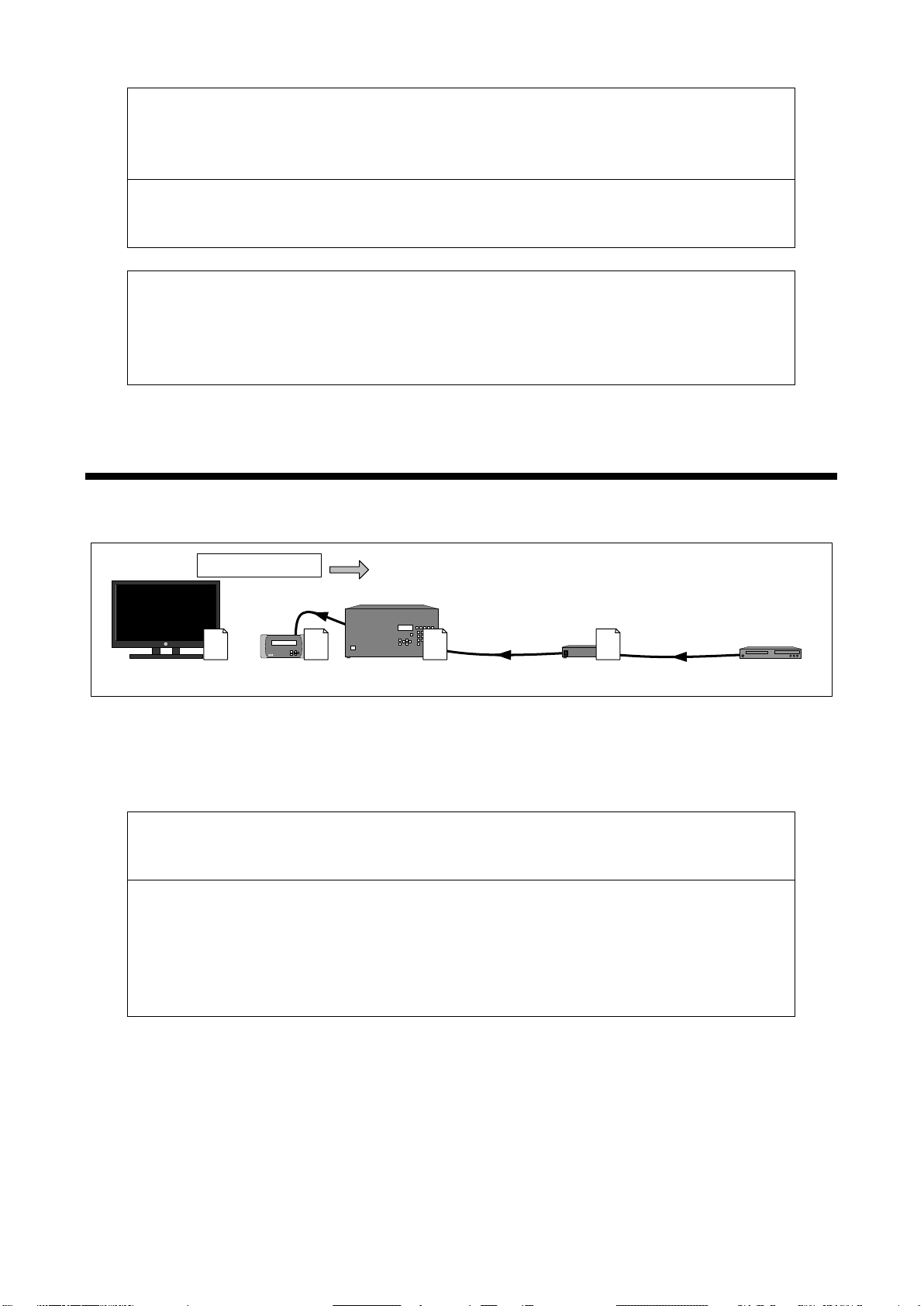
3 Example of use
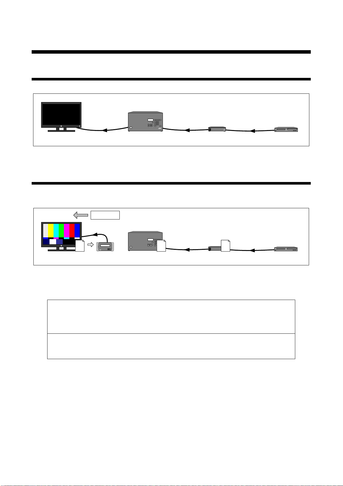
3.1 Application example
The illustration below is one example of implementing the GF-100.
[Fig. 3.1] Example of system configuration
3.2 Sink test
Remove cable 1 from the switcher and connect the GF-100 in order to perform the sink test (P.34) for the sink
device and cable 1.
[Fig. 3.2] Sink test
■ Checking sink status (P.34)
Check if the GF-100 can detect the sink device correctly (P.35).
<If the GF-100 cannot detect the sink device>
The sink device or cable 1 has a problem. Check the power supply, connection and input
switching (if there are some) of the sink device.
Perform the cable test (P.48) for cable 1 if necessary.
<If the GF-100 can detect the sink device>
Check the following specification of the sink device,: supported resolution, color space, color
depth (Deep Color) and whether audio and HDCP are suppor te d.
■ Checking operation using test patterns/tones (P.39)
Change the following settings of test patterns/tones to check the sink device operation.
(Default values are set for all settings.)
● Resolution
● The presence or absence of audio
● The presence or absence of HDCP
● Color space
● Color depth (Deep Color)
12
Page 13
GF-100 User’s Guide
headphones connection, and audio input setting.
<If there is no problem or test pattern is not displayed in a specific setting>
source test.
GF-100
EDID
1
EDID
3
EDID
2
EDID
1
Source device test
Cable 1
BD playerMonitor
Distribution
amplifier
Switcher Cable 3
Cable 2
②
<If signals cannot be detected>
signals still cannot be det ec ted, per f orm the sink test of the switcher (③ Fig.3.4).
<If signals can be detected>
<If a test pattern is not displayed>
The sink device or cable 1 has a problem. Check the power supply, connection and input
switching (if there are some) of the sink device.
Perform the cable test (P.48) for cable 1 if necessary.
<If a test tone is not output to the sink device that supports audio>
Check the following items: volume of sink device, m ute setti ng, the pr esenc e or absence of
Perform the source test (② Fig. 3.3).
Immediately after the sink device and GF-100 are connected, the EDID of the sink device will
be copied into the GF-100 automatically. The copied EDID is used by the switcher during the
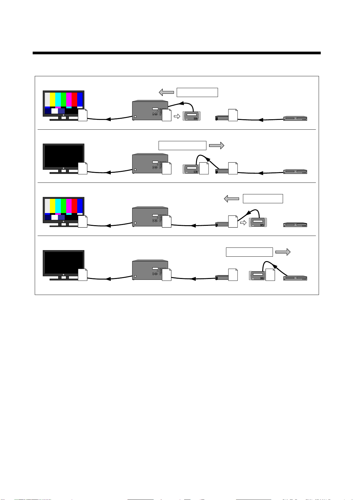
3.3 Source test
Test for switcher, distribution amplifier, BD player, cable 1 to 3 (P.19). Connect the switcher and GF-100 as
shown below.
[Fig. 3.3] Source test
■ Checking source status (P.19)
Check if source signals can be detected correctly (P.21).
Check the power supply of the switcher, connection and channel switching setting. If the source
Check the following items: the resolution of the source signals, the presence or absence of
audio and HDCP, color space, color depth (Deep Color), and other items.
If source signals that are not supported by the sink device are sent, cha nge the B D pla yer
settings and EDID of the distribution amplifier, and other actions in order to resolve the problem.
If no problem is found, perform the sink test of the switcher (③ Fig.3.4).
13
Page 14
GF-100 User’s Guide
EDID
2
EDID
2
EDID
1
EDID
1
EDID
2
EDID
1
EDID
2
EDID
1
EDID
2
EDID
3
EDID
3
EDID
3
EDID
3
EDID
3
③
Sink device test
④
⑤
⑥
Sink device test
Source device test
Source device test
BD playerMonitor
Distribution
amplifier
Switcher
Cable 3
Cable 2Cable 1
Copy
Copy
GF-100
3.4 Re pe ating source and sink tests
Repeat the source and sink tests between devices until the cause of the problem is identified.
[Fig. 3.4] Repeating source test and sink test
14
Page 15
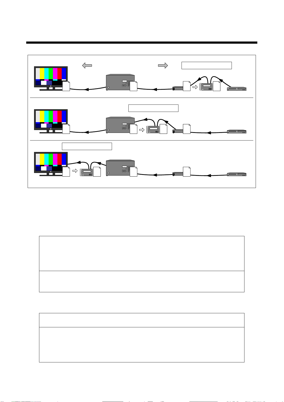
3.5 Te s t fr om source device
EDID
2
①
Sink/
Source test
EDID
3
Copy
EDID
3
EDID
1
EDID
3
②
EDID
1
EDID
2
Copy
EDID
2
Sink/Source test
EDID
1
Copy
EDID
3
EDID
1
GF-100
Cable 1
BD playerMonitor
Distribution
amplifier
Cable 3Cable 2
③
EDID
2
Switcher
Sink/Source test
Cable for test
Cable for test
Cable for test
Sink device
side
Source device
side
If the test pattern is still not displayed, perform ② above ([Fig. 3.5]).
HDCP, color space, and color depth (Deep Color) and then perform the source test.
Check the power supply of the source device and connection.
<If signals can be detected>
settings and EDID of the distribution am plifier .
Prepare a cable for the test to copy the EDID of the sink device.
GF-100 User’s Guide
[Fig. 3.5] Test from source device side
■ Checking operation using test patterns/tones (P.39)
The following items are set automatically by default depending on the performance of the sink device:
resolution of the test patterns/tones, the presence or absence of audio, the presence or absence of
HDCP, color space, and color depth (Deep Color).
<If a test pattern is not displayed>
Check the power supply, connection and input switching (if there are some inputs) of sink
device.
Perform the cable test (P.48) if necessary.
<If a test pattern is displayed>
Check the following items: resolution of the test pattern, the pres enc e or abse nc e of audio and
■ Checking source status (P.19)
Check if source signals are detected correctly. (P.21)
<If signals cannot be detected>
Check the following items: the resolution of the source signals, the presence or absence of
audio and HDCP, color space, color depth (Deep Color), and other items.
If source signals that are not supported by the sink device are sent, change the BD player
15
Page 16
GF-100 User’s Guide
⑧
⑨
① ②
③ ④
⑤ ⑥
⑦
#
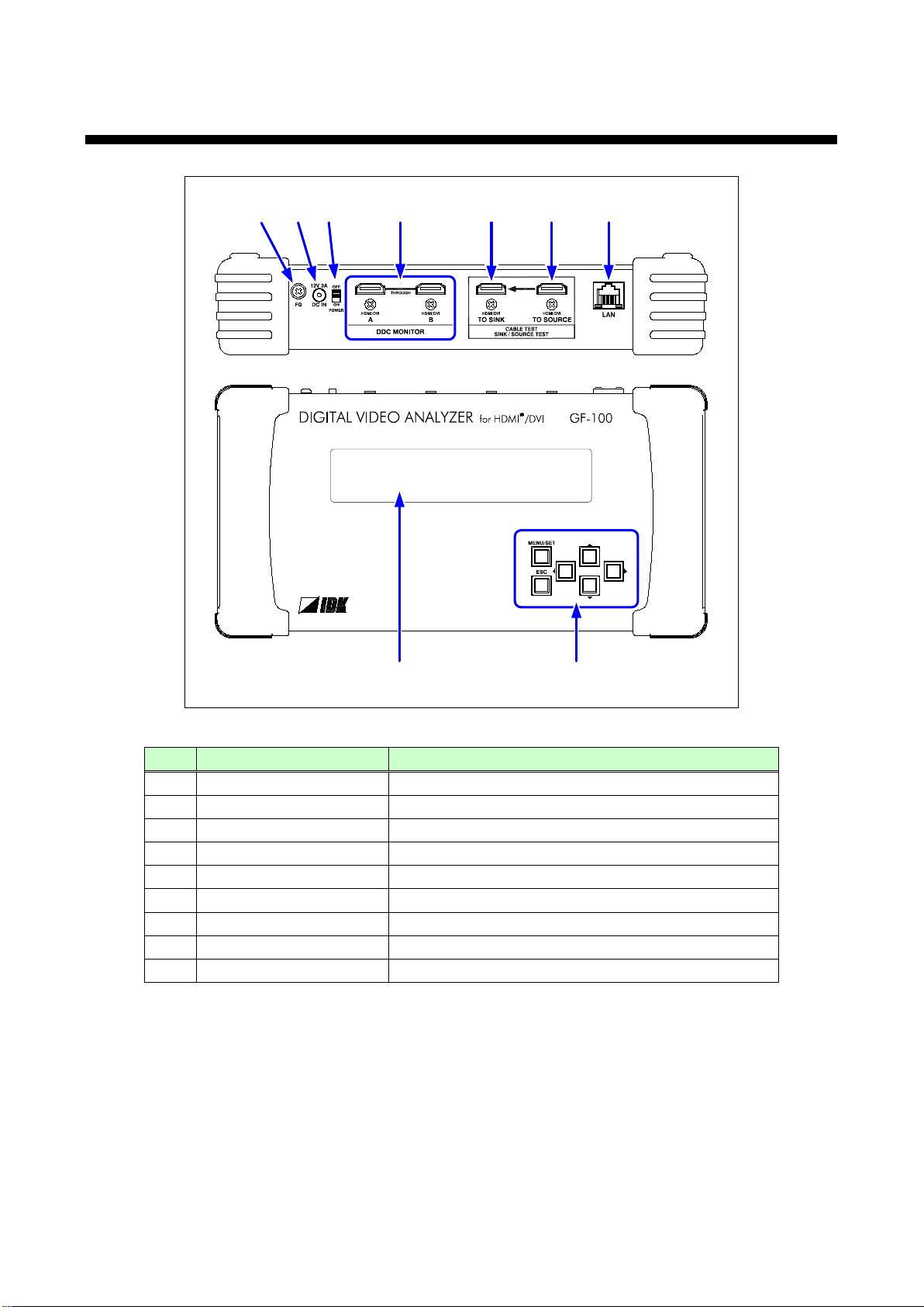
Part name
Description
Frame ground
For indoor ground terminal. An M4 screw is used.
Power supply connector
For provided AC adapter.
Main power switch
Turns on/off the GF-100.
DDC monitor connector
For DDC monitor.
Sink test connector
For sink test and cable/transmission path test.
Source test connector
For source test and cable/transmission path test.
LAN port
For browser.
LCD display
Displays menus, setting, and statuses.
Menu operation keys
For menu operation.
4 Top and rear panel
①
②
③
④
⑤
⑥
⑦
⑧
⑨
[Fig. 4.1] Drawing
16
Page 17
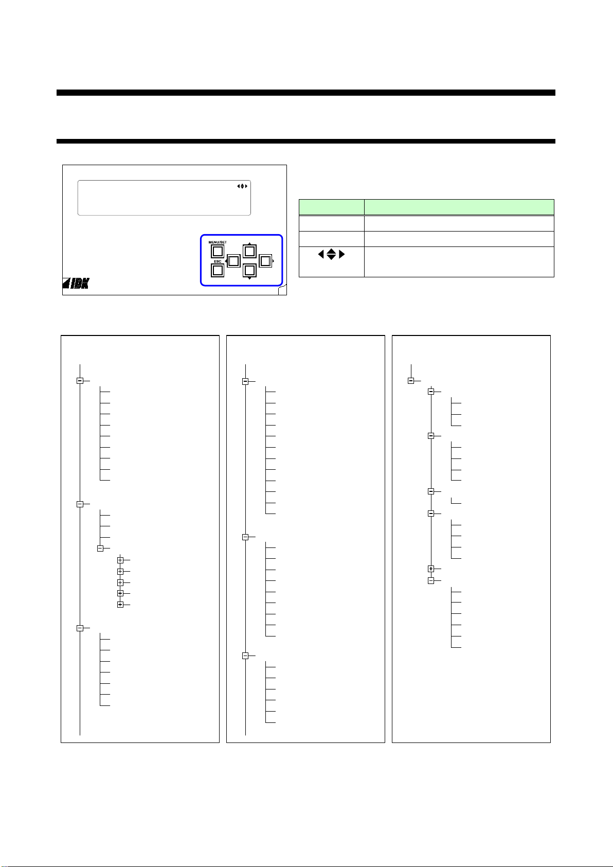
5 Basic operation
Moves cursor/page and changes set
SOURCE STATE
SUMMARY
VIDEO TIMING
VIDEO FREQ.
AUDIO STATE 1
AUDIO STATE 2
AVI INFO
SPD INFO
AUDIO INFO
1
AUDIO INFO 2
TOP
CABLE TEST
RESOL.
AMOUNT
COL.DEPTH
CAPT.WAIT
START
(RESULT)
TEST PATTERN
OUTPUT
CONTENTS
RESOLUTION
HDCP OUT
FORMAT
COLOR DEPTH
TEST TONE
TONE CH
TONE LEVEL
EDID OUT
EDID MODE
EDID CAPTURE
RESOLUTION
COLOR DEPTH
AUDIO CHANNEL
PCM
Dolby Digital
AAC
Dolby Digital+
DTS
DTS-HD
Dolby TrueHD
DDC MONITOR
STATUS
HP/DDC LOG
EDID LOG
HDCP LOG
OTHERS LOG
BUZZER
ESCAPE CODE
SINK STATE
SUMMARY 1
SUMMARY
2 TIMING
SUMMARY 3 SPEAK
SINK EDID
BASIC
EXTENSION #1
EXTENSION #2
EXTENSION #3
EXTENSION #4
SETTINGS
SOURCE LOG
BUZZER
ESCAPE CODE
DETECT WAIT
VIDEO INPUT
SIGNAL REQUEST
RECV OFFSET
HDCP INPUT
BUS RESET TIME
VIDEO OUTPUT
FORCED OUT
LAN
IP ADDRESS
GATEWAY ADDR
.
SUBNET MASK
MAC ADDRESS
CLOCK
OTHERS
BACKLIGHT OFF
BUZZER
RESUME
FIRM VER.
BOAD VER.
FPGA VER.
TOP
2014/
06
/ 01( SUN) 00: 00
SOURCE STATE
|
EDID OUT | SETTINGS
SINK STATE | TEST PATTERN |
DDC MONITOR | CABLE TEST |
【
】
5.1 Menu operation
[Fig. 5.1] Menu operation keys
GF-100 User’s Guide
[Table 5.1] Function of menu operation key
Key Function
MENU/SET Enters the menu and applies setting.
ESC Exits from the menu.
value.
[Fig. 5.2] Menu list
17
Page 18
GF-100 User’s Guide
Press and hold this
key for
3 seconds.
KEY LOCKED.
Hold this key and
turn on GF
-100.
GF-100 Ver.0.00
IDK Corporation
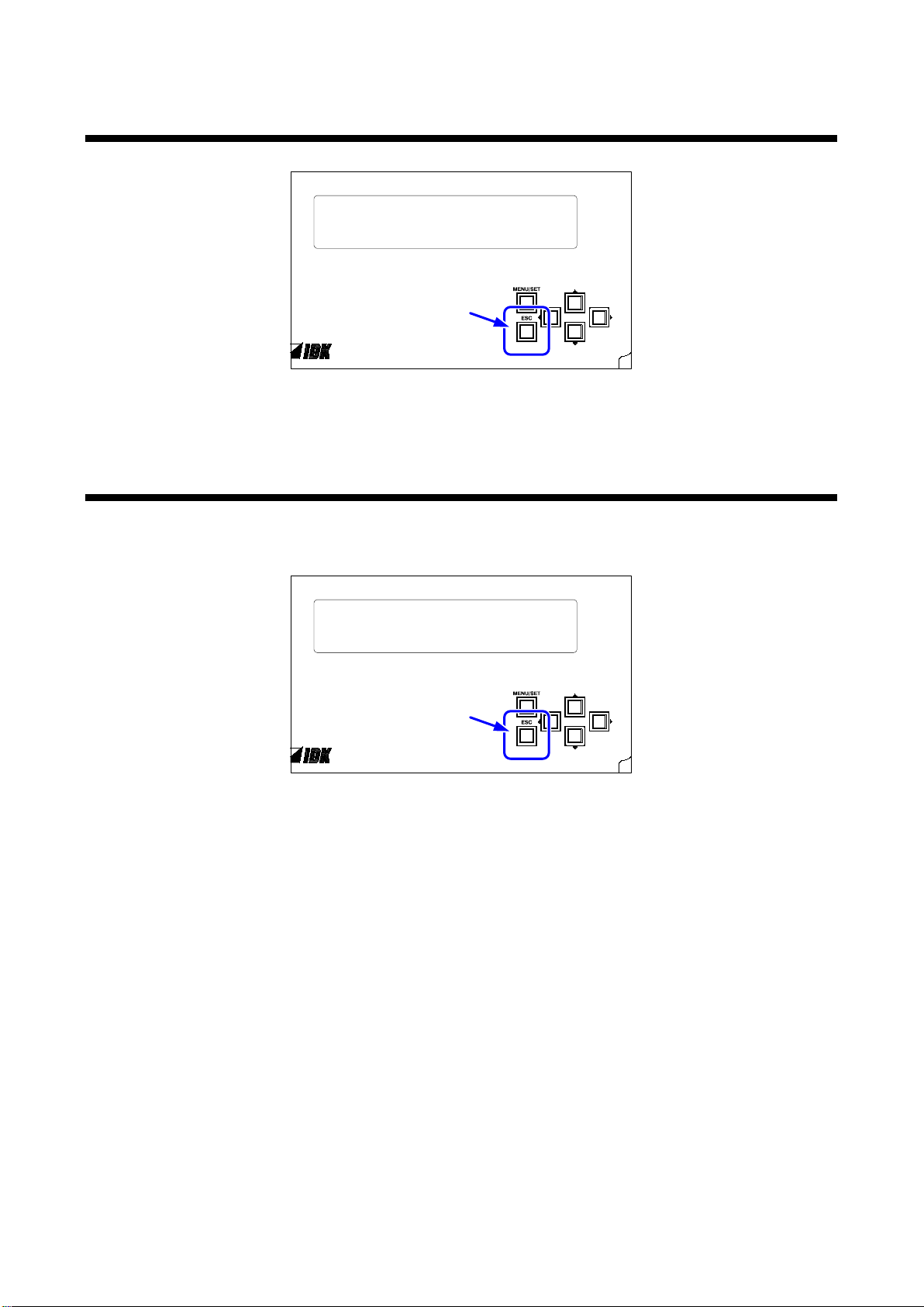
5.2 Setting/canceling key lock
Press and hold the “ESC” key for 3 seconds (approx.) to enable/disable the key lock.
[Fig. 5.3] Key lock
5.3 Initialization
Turn on the GF-100 while holding the “ESC” key, and all settings will be initialized (to factory default). Hold the
key until you hear a beep sound.
[Fig. 5.4] Initialization
18
Page 19
6 Source test
Source test connector
GF-100
Source device
Source test connecotr
Source device
Sink test connector
GF-100
Sink device
EDID
Copy
GF-100
EDID
① Copying EDID (connecting sink device for 2 seconds) ② Source test
GF-100 pretends to
be the sink device
6.1 Displaying source status
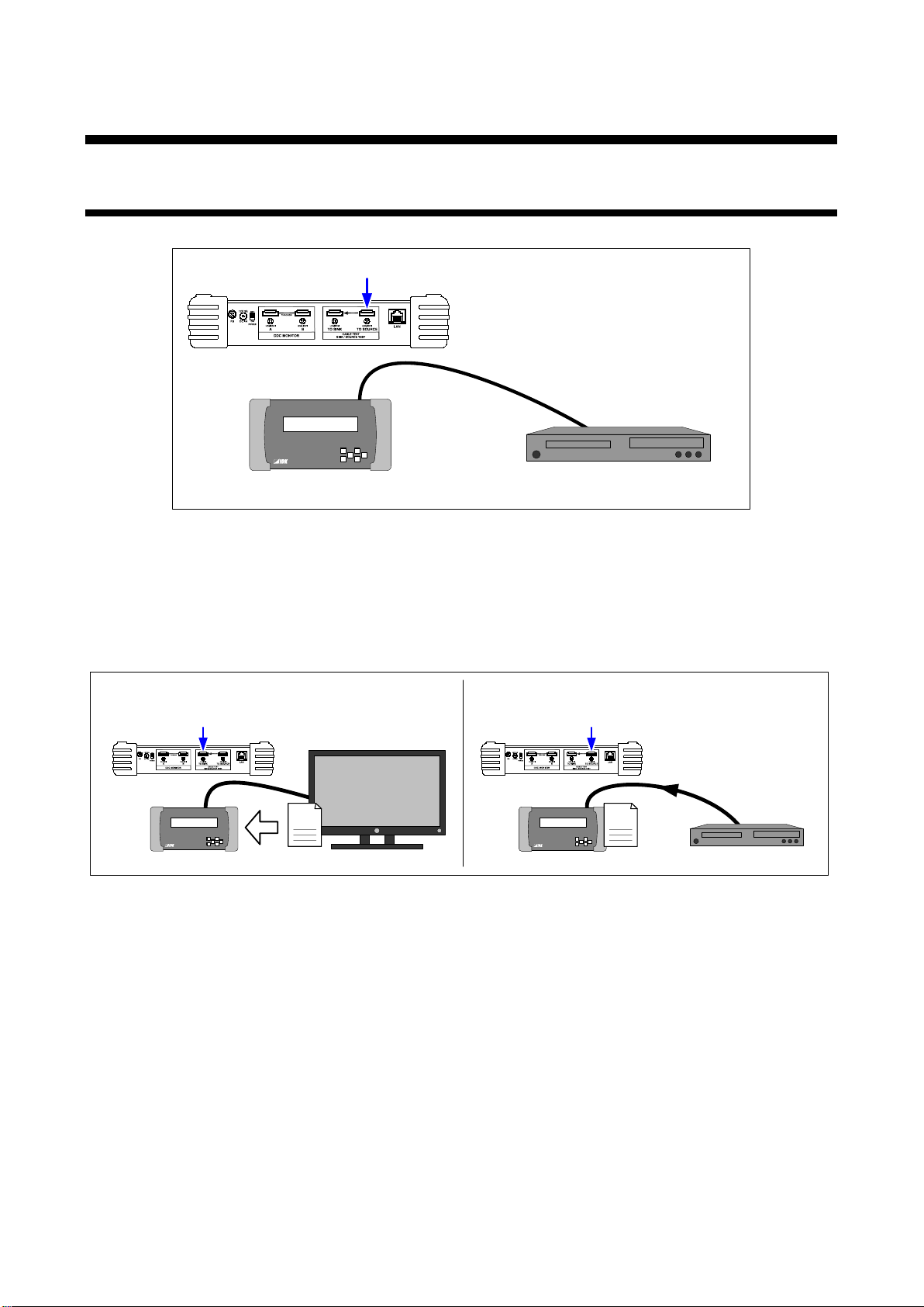
Status of the device that is connected to the source test connector can be displayed.
GF-100 User’s Guide
[Fig. 6.1] Connection for source test
We recommend that you copy EDID of the sink device in advance and set it to the source test connector in
order to acquire the same status as the actual operation.
If the EDID output mode (P.30) is set to “AUTO” (Default), connect the sink device to the sink test connector
for 2 seconds at least in order to copy the EDID correctly.
[Fig. 6.2] Copying EDID
19
Page 20
GF-100 User’s Guide
Menu page
Displaying information
Information Code)
VIDEO FREQ.
(Audio signals)
AUDIO STATE 2
(AVI InfoFrame)
(SPD InfoFrame)
AUDIO INFO 1
(AUDIO InfoFrame)
Menu
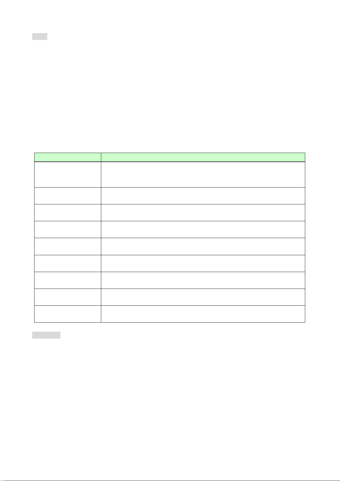
TOP → SOURCE STATE → Table 6.1 below
The summary information of the source signals is shown on the SUMMARY page.
Very detailed information is shown on pages other tha n the SUMMARY page.
<Reference>
HDMI1.4: High-Definition Multimedia Interface Specification Version 1.4
CEA-861: CEA Standard A DTV Profile for Uncompressed High Speed Digital Interfaces
Note: The GF-100 is a simplified analyzer for field supports of AV systems. Please note that it does not
provide calibrations.
[Fig. 6.3] Source status menu
SUMMARY
(Source signals)
VIDEO TIMING
(Video signals timing)
(Video frequency)
AUDIO STATE 1
(Audio signals)
AVI INFO
SPD INFO
(AUDIO InfoFrame)
AUDIO INFO 2
WEB page
http://The GF-100’s IP address/source_state.html
“The GF-100’s IP address” refers to the assigned IP address given to the GF-100. The default IP address
is 192.168.001.199, and it can be changed using the settings in section “10.4.1 IP address”.
Resolution, frame rate, aspect ratio, HDMI/DVI, color space, color depth, DDC
voltage, audio format, presence or absence of HDCP, and VIC (Video
Total number of dots/lines, active area, back porch, front porch, synchronous
signals polarity, scanning method
Frame rate, horizontal synchronous signals, dot clock
Sampling frequency information, audio format, and other information
Other additional information
Color space, color range, aspect ratio, and other information
Manufacturer inform ation
Speaker configuration
Audio format, the number of channels, and other information
20
Page 21
GF-100 User’s Guide
TOP > SOURCE STATE [ 1 / 9 ] SUMMARY
NO SIGNAL
DDC= 0 . 26V
● Replace the cable.
TOP > SOURCE STATE [ 1 / 9 ] SUMMARY
1920x 1080p , 59. 94Hz, 16: 9 , VIC= 16
HDMI, HDCP, RGB, 8 bit COLOR, DDC= 5 . 00V
PCM, 2 CH, 48kHz, 24bit, NOT HI- BIT
1920
1080
6.2 Displaying source status (example)
6.2.1 Detecting source signals
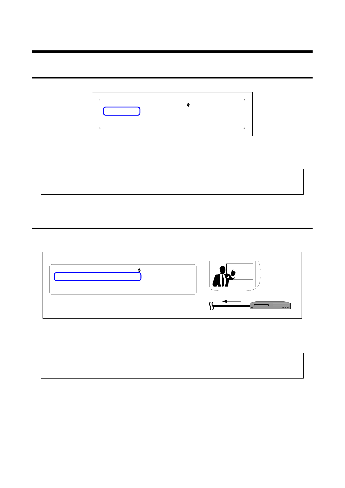
If the GF-100 does not detect source signals, “NO SIGNAL” is displayed.
[Fig. 6.4] Signals are not detected
<Recommended actions>
● Check the connection, power supply of the sourc e de vic e, and external output settings (laptop)
● Perform the cable test (P.48)
6.2.2 Video timing (Resolution/scanning method/frame rate/aspect ratio)
Displaying resolution, scanning method, frame rate, and aspect ratio of the source signals.
For the scanning method: “p” means progressive while “i” means interlace.
[Fig. 6.5] Video timing
<Recommended actions for when the image cannot be displayed on the sink device>
● Sink device: Check the power supply, input switching (if there are some inputs), supported
resolution (P.38), and operation using test patterns (P.39).
● Source device: Change the output resolution.
21
Page 22
GF-100 User’s Guide
TOP >
SOURCE STATE [1/9] SUMMARY
1920x
1080p
,
59.94Hz,16:9
DVI,HDCP
,RGB
,
8bit COLOR
,DDC
=
5.
00V
TOP
> SOURCE STATE
[1
/9
]
SUMMARY
1920x
1080p
,59
.
94Hz
,16
:
9,
VIC=
16
HDMI
,
HDCP,
RGB
,8
bit COLOR,DDC=5
.
00V
PCM,2CH,48kHz
,
24bit
,NOT HI
-
BIT
♪
....
DVI
(
without
audio
)
HDMI
(with
audio
)
(P.39).
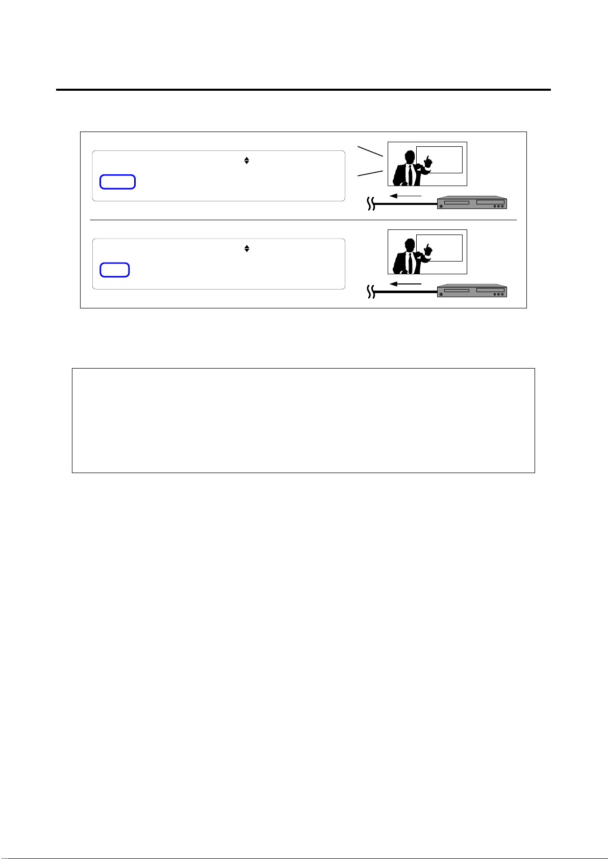
6.2.3 HDMI/DVI (with/without audio)
If the source signals have audio, “HDMI” is displayed while “DVI” is displayed for signals that do not ha ve
audio.
[Fig. 6.6] HDMI/DVI
<Recommended actions>
● When the image cannot be displayed on the sink device;
Check the power supply, input switching (if there are some inputs), and operation using test
patterns (P.39) of the sink device.
● When the audio is not output from the sink device (HDMI supported);
Check the volume, mute, presence or absence of headphone, audio input setting
(analog/digital), audio source (such as silent scene and pause), and operation using test tones
22
Page 23
GF-100 User’s Guide
TOP > SOURCE STATE
[1
/9
]
SUMMARY
1920x1080p
,
59.
94Hz
,
16:
9
,VIC
=16
HDMI,
NO HDCP
,RGB
,8
bit
COLOR,DDC=5.
00V
PCM,2CH,
48
kHz,
24bit
,
NOT HI-
BIT
TOP > SOURCE STATE
[1
/9
]
SUMMARY
1920x1080
p
,59
.94
Hz
,16
:
9,
VIC=
16
HDMI
,
HDCP,
RGB,
8
bit COLOR,DDC=5
.00
V
PCM,2CH,48kHz
,
24bit
,NOT HI
-
BIT
Without HDCP
With HDCP
(Encryption
)
and operation using test patterns (P.39) of the sink device.
TOP > SOURCE STATE [ 1 / 9 ] SUMMARY
1920x 1080p , 59. 94Hz, 16: 9 , VIC= 16
HDMI, HDCP, Y 444, 8 bit COLOR, DDC= 5 . 00V
PCM, 2 CH, 48kHz, 24bit, NOT HI- BIT
TOP > SOURCE STATE [ 1 / 9 ] SUMMARY
1920x 1080p , 59. 94Hz, 16: 9 , VIC= 16
HDMI, HDCP, RGB, 8 bit COLOR, DDC= 5 . 00V
PCM, 2 CH, 48kHz, 24bit, NOT HI- BIT
YCbCr4:4:4
RGB
R
G
B
Y
Cb
Cr
● Source device: Change output color space.
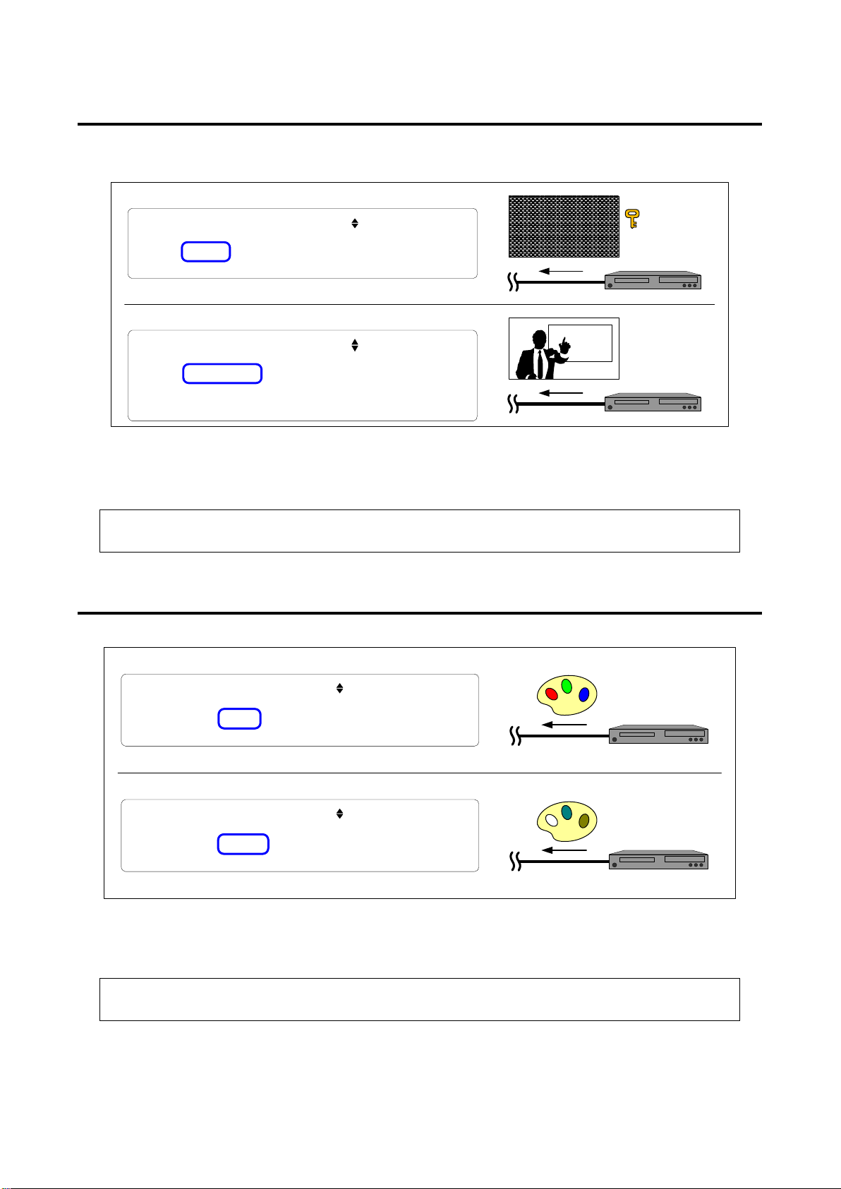
6.2.4 With/without HDCP (copyright protection)
If the source signals include HDCP, “HDCP” is displayed while “NO HDCP” is displayed for signals that do not
have HDCP.
[Fig. 6.7] HDCP
<Recommended actions for when the image cannot be displayed on the sink device>
Check the power supply, input switching (if there are some inputs), HDCP supported/not supported,
6.2.5 Color space
RGB4:4:4: “RGB”, YCbCr4:2:2: “Y422”, YCbCr4:4:4: “Y444”
[Fig. 6.8] Displaying color space
<Recommended actions for when the image is not display with correct colors>
● Sink device: Check the supported color space (P.36) and operation using test patterns (P.39).
23
Page 24
GF-100 User’s Guide
TOP > SOURCE STATE [ 1 / 9 ] SUMMARY
1920x 1080p , 59. 94Hz, 16: 9 , VIC= 16
HDMI, HDCP, RGB, 12bit COLOR, DDC= 5 . 00V
PCM, 2 CH, 48kHz, 24bit, NOT HI- BIT
TOP > SOURCE STATE [ 1 / 9 ] SUMMARY
1920x 1080p , 59. 94Hz, 16: 9 , VIC= 16
HDMI, HDCP, RGB, 8 bit COLOR, DDC= 5 . 00V
PCM, 2 CH, 48kHz, 24bit, NOT HI- BIT
12bit
8bit
● Source device: Change the output color depth.
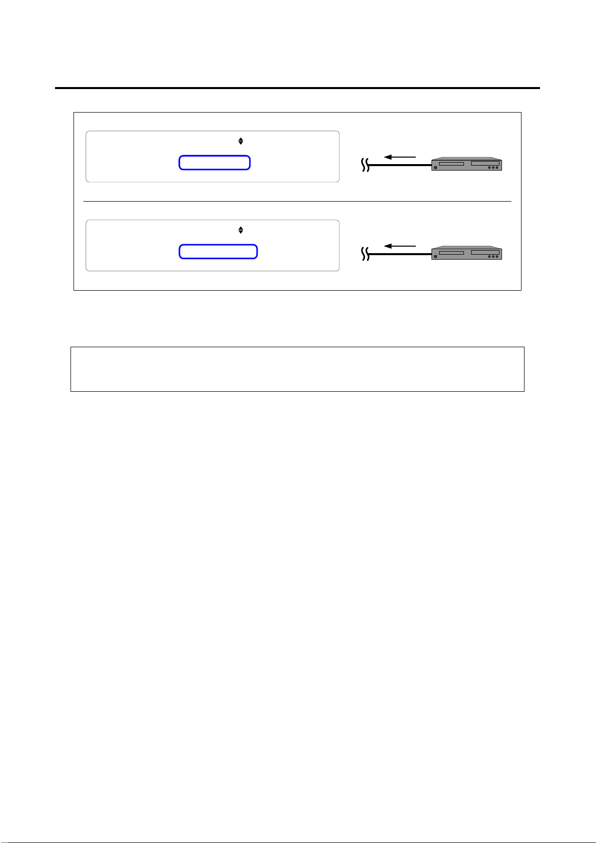
6.2.6 Color depth (D eep Color)
12 bit (36 bit/pixel): “12bit” 10 bit (30 bit/pixel): “10bit” 8 bit (24 bit/pixel): “8bit”
[Fig. 6.9] Displaying color depth
<Recommended actions for when the image cannot be displayed on the sink device>
● Sink device: Check the power supply, input switching (if there are some inputs), supported color
depth (P37), and operation using test patterns (P40).
24
Page 25
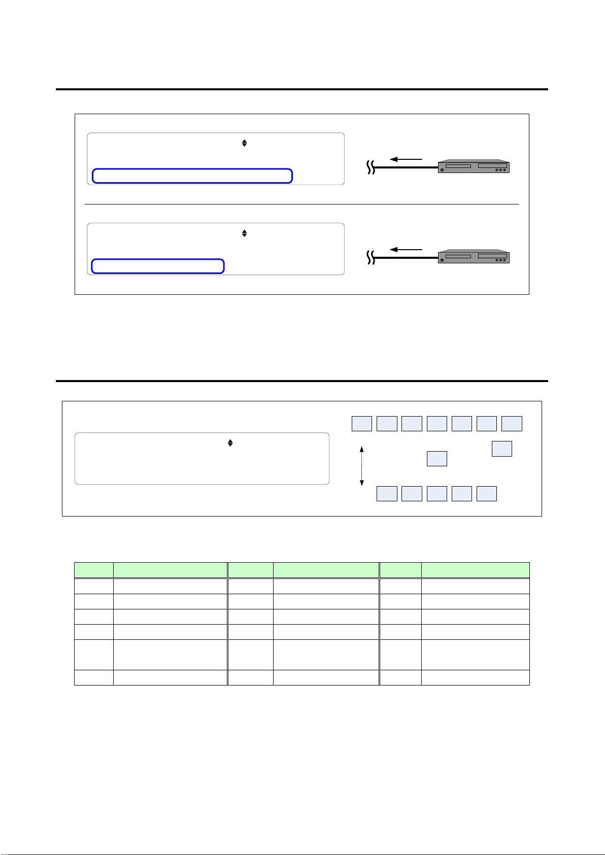
6.2.7 Audio format
♪
Bit stream
(compressed audio)
Linear PCM
TOP > SOURCE STATE [1 / 9 ] SUMMARY
1920x1080p,59. 94Hz, 16: 9,VIC=16
HDMI,HDCP,RGB,8 bit COLOR, DDC= 5.00V
COMPRESSED AUDIO
TOP > SOURCE STATE [1 / 9 ] SUMMARY
1920x1080p,59. 94Hz, 16: 9,VIC=16
HDMI,HDCP,RGB,8 bit COLOR, DDC= 5.00V
PCM,2CH,48kHz, 24bit, NOT HI- BIT
♪
FLW
FL
FLC
FC
FRC
FR
LFE
TC
RC
RLC
RL
RR
FRONT
REAR
FRW
RRC
TOP > SOURCE STATE [ 8
/ 9 ] AUDIO INFO 1
[ --- --- FL ---][--- --][--- FR --- ---]
[ --] [---]
[ -- ---] [--] [--- --]
Effect
Linear PCM: “PCM” Bit stream (compressed audio): “COMPRESS AUDIO”
[Fig. 6.10] Audio format
GF-100 User’s Guide
6.2.8 Speaker configuration
[Fig. 6.11] Speaker configuration
[Table 6.1] Speaker configuration
Name Position Name Position Name Position
FL Front Left RC Rear Center FRW Front Right Wide
FC Front Center RR Rear Right FLH Front Left High
FR Front Right RLC Rear Left Center FCH Front Center High
FLC Front Left Center RRC Rear Right Center FRH Front Right High
FRC Front Right Center LFE Low Frequency
TC Top Center
RL Rear Left FLW Front Left Wide
25
Page 26
GF-100 User’s Guide
6.3 History of source status
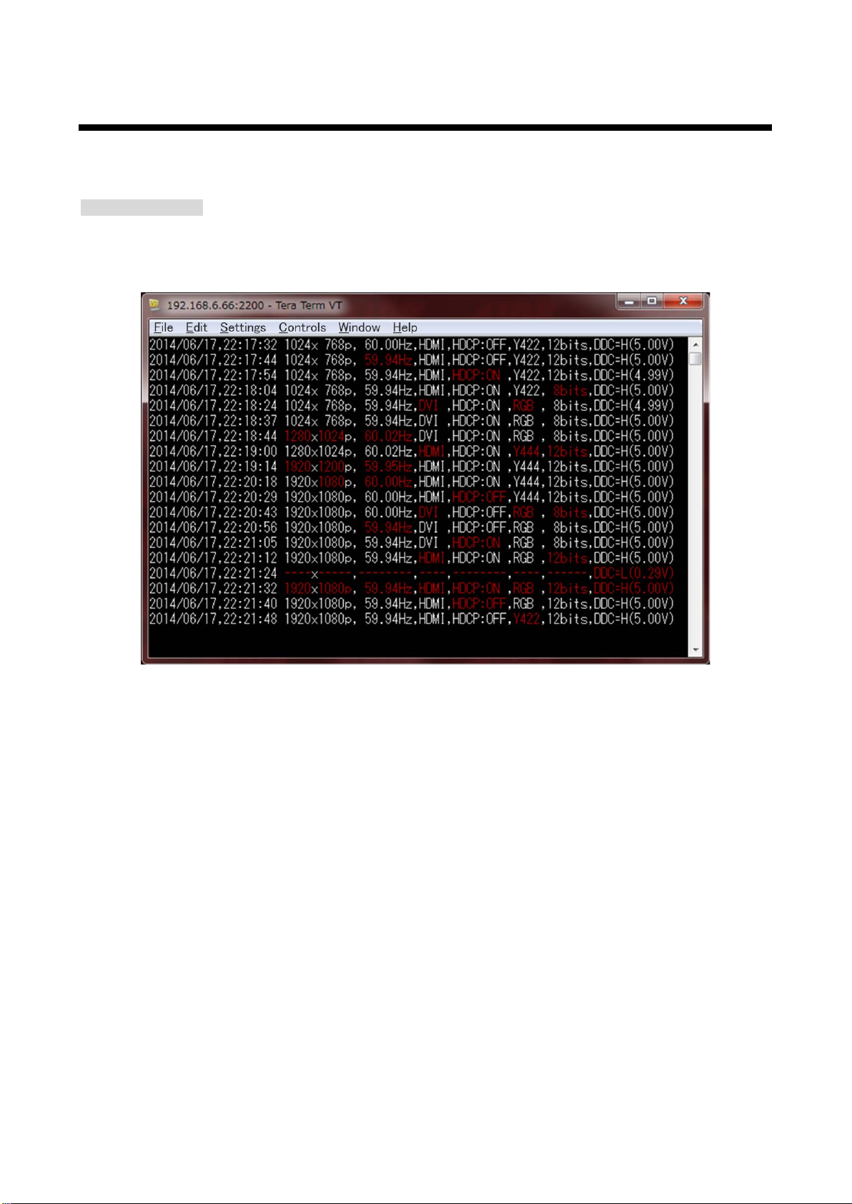
Changes in status (resolution, frame rate, HDMI/DVI, with/without HDCP, color space, color depth, and DDC
voltage) can be output to the browser or TCP/IP port “2200”.
Terminal software
● The source status is output to TCP/IP port “2200”.
● When a status change is detected, BELI code is output, and the changed statuses are displayed in red.
(P.28)
[Fig. 6.12] Source status (Terminal software)
26
Page 27
GF-100 User’s Guide
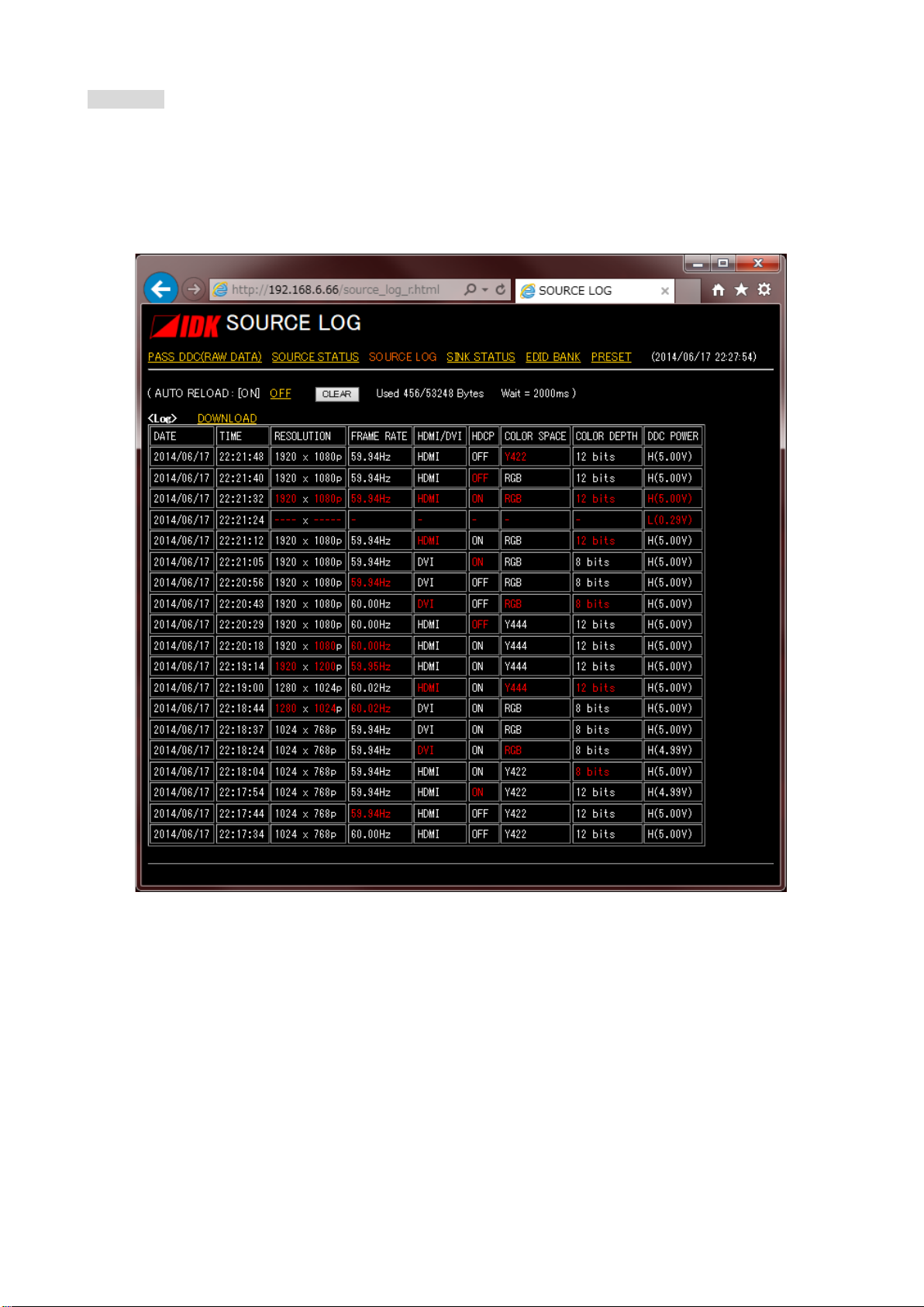
WEB page
http://The GF-100’s IP address/source_log_r.html
● The changed statuses ar e displ a yed in red.
● The history data is kept even after turning off the GF-100.
● When the save area of communication history (53,248 byte) is full, from the oldest data will be deleted.
[Fig. 6.13] WEB page of source status history
27
Page 28

GF-100 User’s Guide
6.3.1 Beep for source status change
Menu
TOP → SETTINGS → SOURCE LOG → BUZZER
Set value
OFF: The beep does not sound [Default]
ON: The beep sounds when the source status changes.
Note: If “10.5.2 Beep sound (P.58)” is set to “OFF”, it does not sound.
6.3.2 Escape sequence of source status
Letter color code and BE LI code are added to the terminal software.
Menu
TOP → SETTINGS → SOURCE LOG → ESCAPE CODE
Set value
DISABLE
ENABLE: The changed status will be shown in red, and warning tone is output from the software every
time the source status changes [Default]
6.3.3 Wait time for detecting source status
The GF-100 waits to detect status of the source device until the status is stabilized.
If you want to detect momentary changes, set the value set this menu to “NO WAIT” or a small value.
If you do not want to detect unnecessary information, set this menu to a larger value.
Menu
TOP → SETTINGS → SOURCE LOG → DETECT WAIT
Set value
NO WAIT
100ms to 10000ms [Default: 800ms]
28
Page 29
6.4 EDID emulator
EDID Bank 1
Original EDID
TO SINK
External EDID buffer
Source device Sink device
EDID Bank 2
EDID Bank 3
EDID Bank 4
EDID Bank 5
TO SOURCE
GF-100
Copy
EDID
EDID output data
Function
(P.32), and audio format (P.33) can be changed.
device for 2 seconds or longer until the copy is completed.
EDID Banks
External EDID settings are saved in the GF-100.
6.4.1 Outline
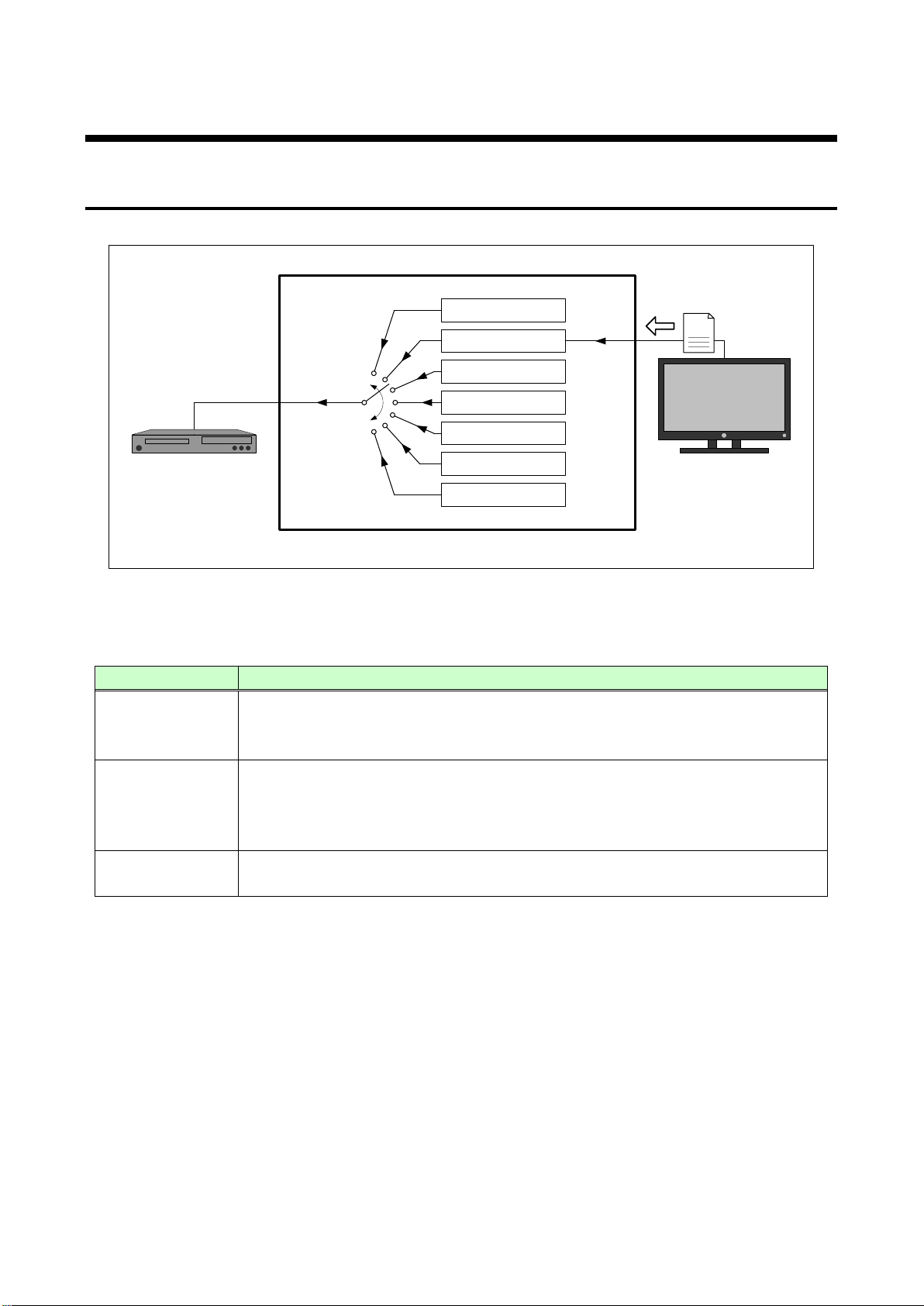
You can set EDID that is output to the connector for source test from the data below.
GF-100 User’s Guide
[Fig. 6.14] EDID output diagram
[Table 6.2] EDID output data
Original EDID of
GF-100
The original EDID of the GF-100
The maximum resolution (P.31), c olor depth (P.31
EDID that is copied from the sink device automatically
External EDID
buffer
1 to 5
When a sink device is connected, the GF-100 copies EDID of the sink device.
The copied EDID is k ept until another sink device is connected. Connect the si nk
Up to five EDIDs that ar e copied to the external EDID buffer can be saved.
Note: Only EDID BLOCK 0 and BLOCK1 are supported.
), the number of audio chan nels
29
Page 30
GF-100 User’s Guide
EDID Bank
1
Original EDID
TO SINK
External EDID buffer
Source
device
Sink device
EDID Bank
2
EDID Bank 3
EDID Bank
4
EDID Bank 5
TO SOURCE
GF-100
Copy
EDID
Set value
Function
EDID Bank 1
Original EDID
External EDID buffer
EDID Bank 2
EDID Bank
3
EDID Bank 4
EDID Bank 5
Save
6.4.2 EDID output mode
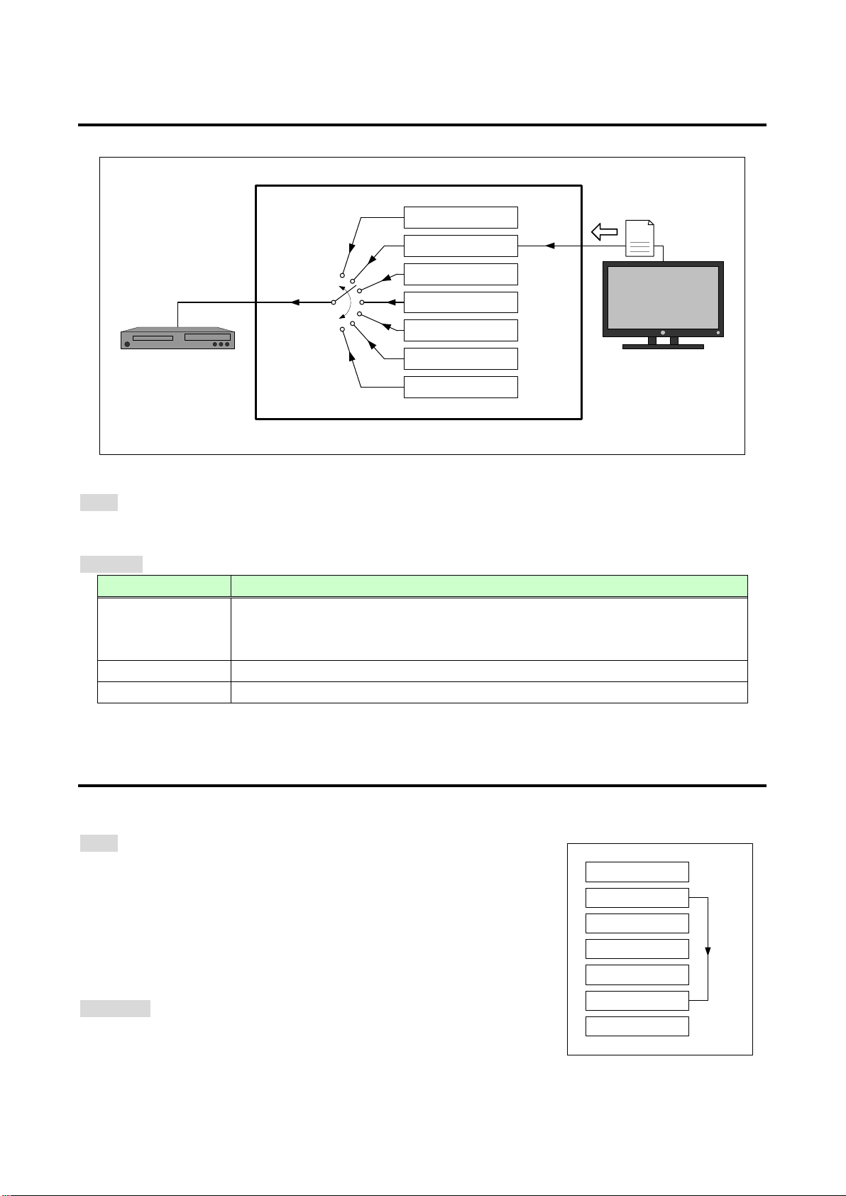
You can select the EDID that is output to the source test connector.
[Fig. 6.15] EDID output diagram
Menu
TOP → EDID OUT → EDID MODE
Set value [Table 6.3] EDID output data
AUTO [Default]
ORIGINAL Outputs the original EDID of the GF-100.
BANK 1 to 5 Outputs EDID banks 1 to 5.
6.4.3 Saving EDID
Saving EDID that is copied in the external EDID buffer into the EDID banks.
EDID banks can be output from the source test connector by setting the EDID mode to BANK 1 to 5.
Menu
TOP → EDID OUT → EDID CAPTURE
The EDID can be saved by selecting the destination bank (BANK 1 to
WEB page
http://The GF-100’s IP address/external_edid_dump.html
You can check the details of the external EDID buffer and EDID bank.
[Fig. 6.16] EDID bank
30
Outputs the external EDID buffer (EDID copied from the sink device).
Outputs the original EDID of the GF-100 if any sink device has not bee n
connected after initialization (P.18).
5) and then press the “SET” key.
The saved EDID can be downloaded from a browser to a PC and
can be read using analysis software.
Page 31
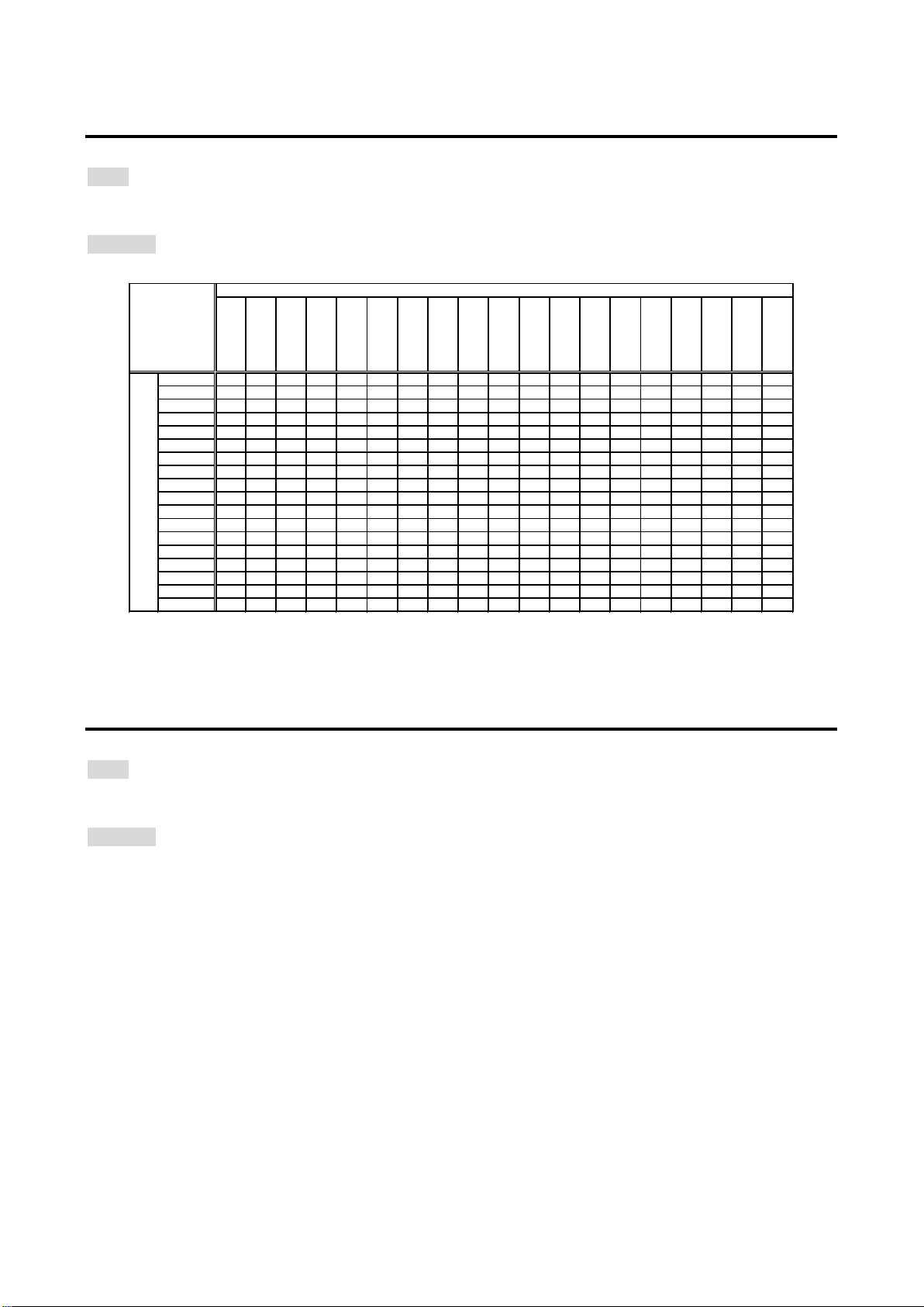
6.4.4 Resolution of original GF-100 EDID
VGA
640 x 480
SVGA
800 x 600
XGA
1024 x 768
720p
1280 x 720
WXGA-1
1280 x 768
WXGA-2
1280 x 800
Quad-VGA
1280 x 960
SXGA
1280 x1024
WXGA-3
1360 x 768
WXGA-4
1366 x 768
SXGA+
1400 x1050
WXGA+
1440 x 900
WXGA++
1600 x 900
UXGA
1600 x1200
WSXGA+
1680 x1050
1080i
1920 x1080
1080p
1920 x1080
WUXGA
1920 x1200
QWXGA
2048 x1152
SVGA
● ●◎
XGA ● ●
●◎
720p ● ● ● ◎
WXGA-1
●
● ●
○ ◎
WXGA-2
● ● ● ○ ◎ ○◎
Quad-VGA
● ●
● ○ ◎ ○ ◎
SXGA ● ● ● ○ ◎ ○ ○ ●◎
WXGA-3
● ●
● ○ ◎ ○ ○ ●○ ◎
WXGA-4 ● ● ● ○ ○ ○ ●○
◎ ◎
SXGA+
● ●
● ○ ○ ○ ●○ ◎ ◎
WXGA+ ● ● ● ○ ○
○ ●○
◎ ○ ◎
WXGA++ ●
● ● ○ ○ ○ ●○ ◎ ○
○ ◎
UXGA
● ● ● ○ ○ ○ ●○ ◎
○ ○ ○
◎
WSXGA+ ●
● ● ○ ○ ○ ●○ ◎ ○
○ ○ ○ ◎
1080i
● ● ● ○ ○ ●○
◎ ○ ○
○ ○ ○ ◎
1080p ● ● ● ○
○ ●○ ○
○ ○ ○ ○ ◎ ◎
WUXGA
● ● ● ○ ○ ●○
○ ○ ○ ○ ○ ◎ ◎
QWXGA ● ● ● ○ ●○
○ ○ ○ ○ ○ ◎ ○ ◎
Set value
Supported resolution
Menu
TOP → EDID OUT → RESOLUTION
Set value [Default: 1080p]
[Table 6.4] EDID output data
GF-100 User’s Guide
●:Established Timing / ○:Standard Timing Identification / ◎:Detailed Timing Description
VESA Enhanced EDID Standard Release A, Rev1
6.4.5 Color depth of original GF-100 EDID
Menu
TOP → EDID OUT → COLOR DEPTH
Set value
24 bit [Default]
24/30 bit
24/30/36 bit
31
Page 32
GF-100 User’s Guide
7.1 CH [Default]
● ● ● ● ● ● ●
●
FL
FC
FR
RL
RR
RLC
RRC
LFE
: Front Left
: Front Center
: Front Right
: Rear Left
: Rear Right
: Rear Left Center
: Rear Right Center
: Low Frequency Effect
FC
FL
FR
LFE
RL
RR
RLC
RRC
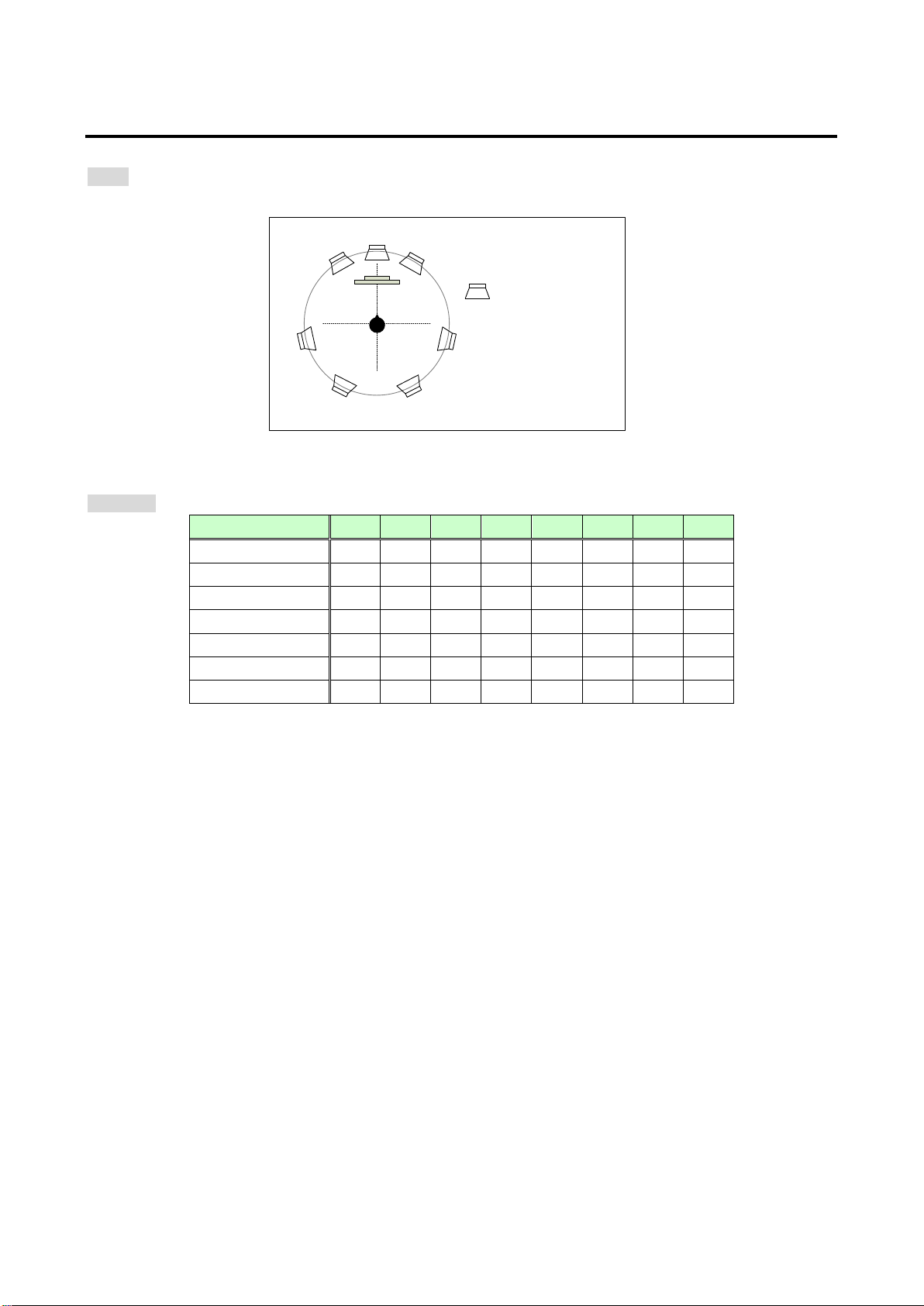
6.4.6 Number of audio channels of original GF-100 EDID
Menu
TOP → EDID OUT → AUDIO CHANNEL
[Fig. 6.17] Speaker configuration
Set value [Table 6.5] EDID output data
Set value RLC RL FL FC FR RR RRC LFE
2 CH ● ●
2.1 CH ● ● ●
3.1 CH ● ● ● ●
5 CH ● ● ● ● ●
5.1 CH ● ● ● ● ● ●
7 CH ● ● ● ● ● ● ●
●: Supported
32
Page 33
GF-100 User’s Guide
Digital Audio.
AAC
Sets availability and the maximum sampling frequency of AAC Audio.
MAX 48.0 kHz
Audio.
kHz
Audio.
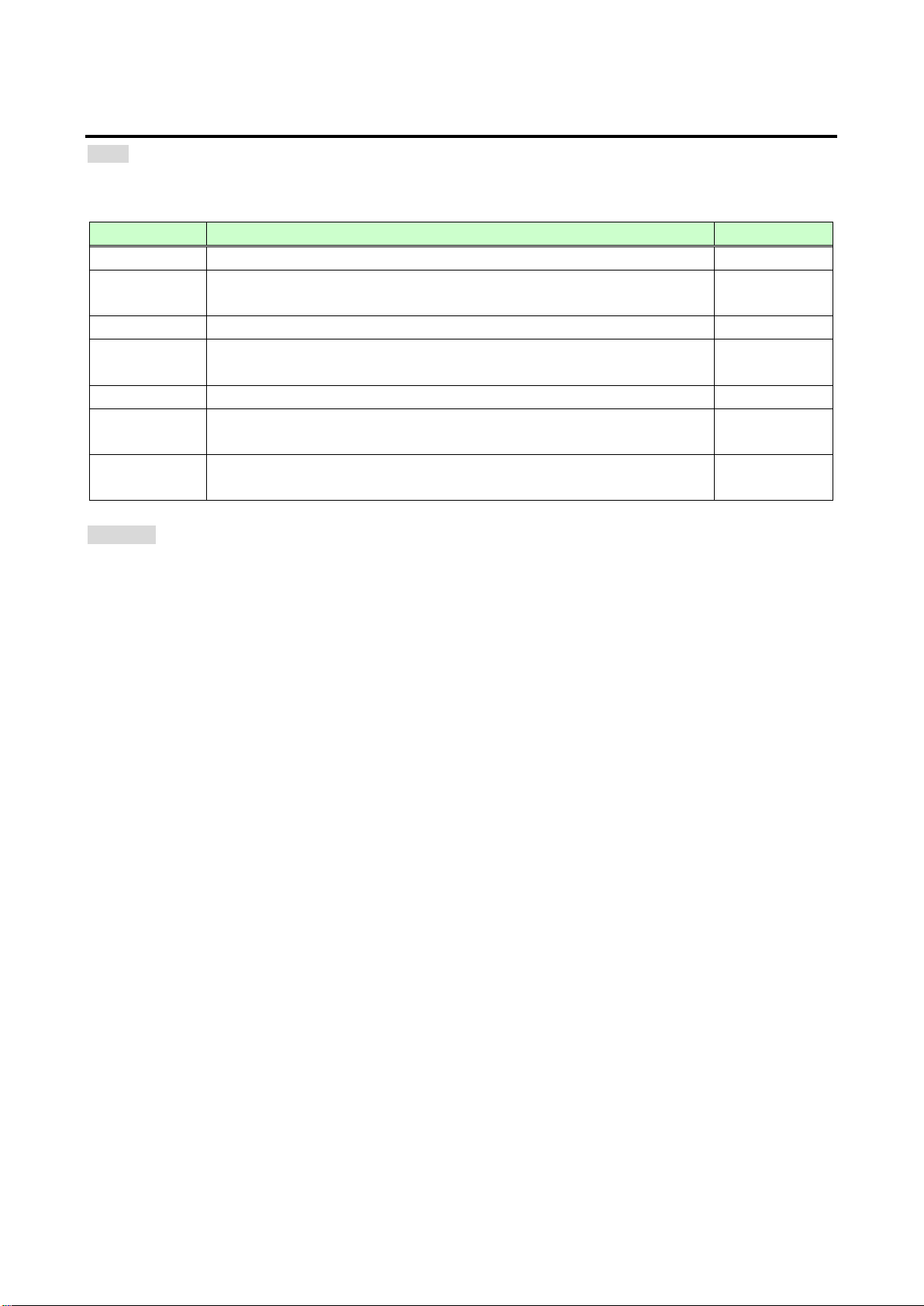
6.4.7 Audio format of original GF-100 EDID
Menu
TOP → EDID OUT → Table 6.4.7 below
[Table 6.6] Audio format settings
Menu Function Default
PCM Sets the maximum sampling frequency of the linear PCM. MAX 48.0 kHz
Dolby Digital Sets availability and the maximum sampling frequency of AC-3 Dolby
MAX 48.0 kHz
Dolby Digital+ Sets availability and the maximum sampling frequency of Dolby Digital
Plus Audio.
DTS Sets availability and the maximum sampling frequency of DTS Audio. MAX 48.0 kHz
DTS-HD Sets availability and the maximum sampling frequency of DTS-HD
Dolby TrueHD Sets availability and the maximum sampling frequency of Dolby TrueHD
Set value
OFF, MAX 32.0 kHz, MAX 44.1 kHz, MAX 48.0 kHz,
MAX 88.2 kHz, MAX 96.0 kHz, MAX 176.4 kHz, MAX 192.0 kHz
MAX 48.0 kHz
MAX 192.0
MAX 96.0 kHz
33
Page 34
GF-100 User’s Guide
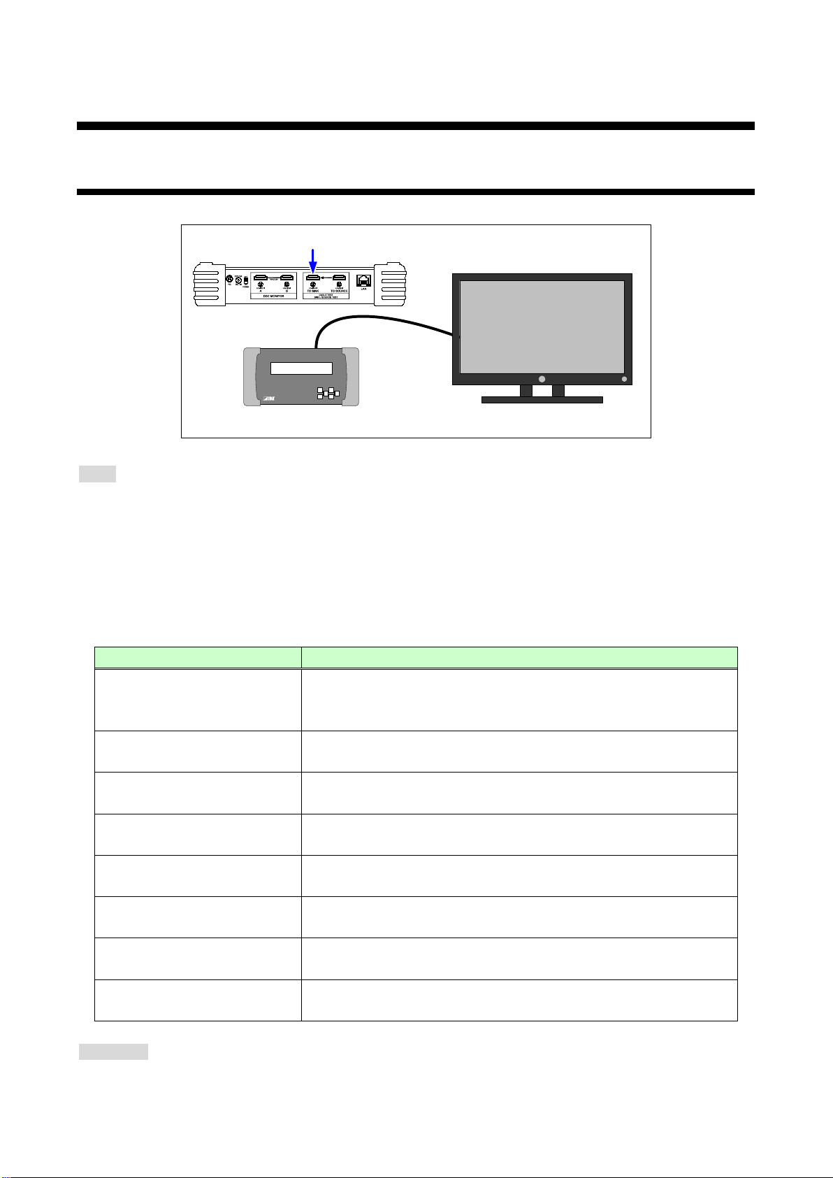
Sink test connector
GF
-100 Sink device
Menu page
Information to be displayed
Manufacturer, product ID, display size, aspect ratio, HDMI
supported color space and color depth
(Specification of sink device)
(EDID detail information)
SINK EDID → EXTENSION #1
(EDID detail information)
(EDID detail information)
7 Sink test
7.1 Sink status
Displaying status of the device that is connected to the sink test connector
[Fig.7.1] Sink test connection
Menu
TOP → SINK STATE →Table 7.1
The specification of the sink device is shown on the SUMMARY pages 1 to 3.
Very detailed information is shown on pages other tha n the SUMMARY page.
<Reference>
E-EDID: VESA Enhanced Extended Display Identification Data Standard Release A, Revision 2
CEA-861: CEA Standard A DTV Profile for Uncompressed High Speed Digital Interfaces
[Table 7.1] Sink status menu
SUMMARY 1
(Specification of sink device)
SUMMARY 2 TIMING
(Specification of sink device)
SUMMARY 3 SPEAK
SINK EDID → BASIC
(EDID detail information)
SINK EDID → EXTENSION #2
SINK EDID → EXTENSION #3
(EDID detail information)
SINK EDID → EXTENSION #4
WEB page
http://The GF-100’s IP address/sink_state.html
supported/not supported, HDCP compliant/ not compliant,
Supported resolution (PREFER, NATIVE)
Speaker configuration
Detail information of BASIC EDID (BLOCK0)
Detail information of EXTENSION #1 EDID (BLOCK1)
Detail information of EXTENSION #2 EDID (BLOCK2)
Detail information of EXTENSION #3 EDID (BLOCK3)
Detail information of EXTENSION #4 EDID (BLOCK4)
34
Page 35
GF-100 User’s Guide
TOP > SINK STATE [ 1 / 4 ] SUMMARY 1
NO SINK
● Replace the cable.
♪
TOP > SINK STATE [1/4] SUMMARY 1
IDK 001H
DVI&HDMI, HDCP:OK, NOT
REPEATER
R 444/Y422/Y444, 8/10/ 12bit
TOP >
SINK STATE [1/4] SUMMARY
1
IDK 001H
DVI, HDCP:OK, NOT REPEATER
R 444, 8bit
Audio is not
output
Audio is output
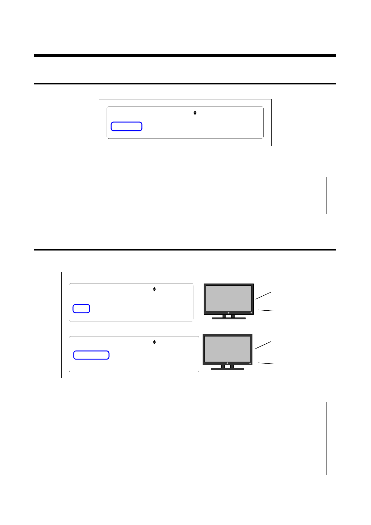
7.2 Displaying sink status
7.2.1 Detecting sink device
If the GF-100 cannot detect sink device, “NO SINK” is displayed.
[Fig.7.2.1] Sink device is not detected
<Recommended actions>
● Check the connection, power supply, and input switching (if there are some inputs) of the sink
device.
● Perform the cable test (P.48).
7.2.2 HDMI (Audio) supported/not supported
If the connected sink device does not support HDMI (audio), “DVI” is displayed while “DVI&HDMI” is displayed
for devices that support HDMI. Sink devices that do not support HDMI cannot output audio.
<Recommended actions>
For when the image cannot be displayed on the sink device;
● Check the power supply, input switching (if there are some inputs), and operation using test
● patterns (P.39) of the sink device
● Check the presence or absence of output signals of the source device (P.21)
For when the audio is not output from the sink device (HDMI supported);
● Check the volume, mute, presence or absence of headphone, audio input setting (analog/digital),
and operation using test tones (P.39) of the sink device.
● Check the presence or absence of audio output (P.22)
[Fig. 7.1] HDMI supported/not supported
35
Page 36
GF-100 User’s Guide
TOP
> SINK STATE
[ 1 / 4 ] SUMMARY 1
IDK 001H
DVI& HDMI, HDCP: NG, NOT REPEATER
R 444/ Y 422/ Y 444, 8 / 10/ 12bit
TOP >
SINK STATE [
1 /
4 ] SUMMARY 1
IDK 001H
DVI&
HDMI, HDCP: OK, NOT REPEATER
R 444/
Y
422/
Y 444, 8 / 10/ 12bit
HDCP
HDCP
● Check the presence or absence of output signals (P.21) and HDCP (P.23) of the source device.
Y
Cb
Cr
Y
Cb
Cr
TOP > SINK STATE
[ 1 /
4 ] SUMMARY 1
IDK 001H
DVI&
HDMI, HDCP: OK, NOT REPEATER
R 444, 8 / 10/ 12bit
TOP > SINK STATE [ 1 / 4 ] SUMMARY 1
IDK 001H
DVI& HDMI, HDCP: OK, NOT REPEATER
R 444/ Y 422/ Y 444, 8 / 10/ 12bit
R
G
B
R
G
B
4
4
4
4
2
2
Source device: Change the color space of the output signals (P.23)
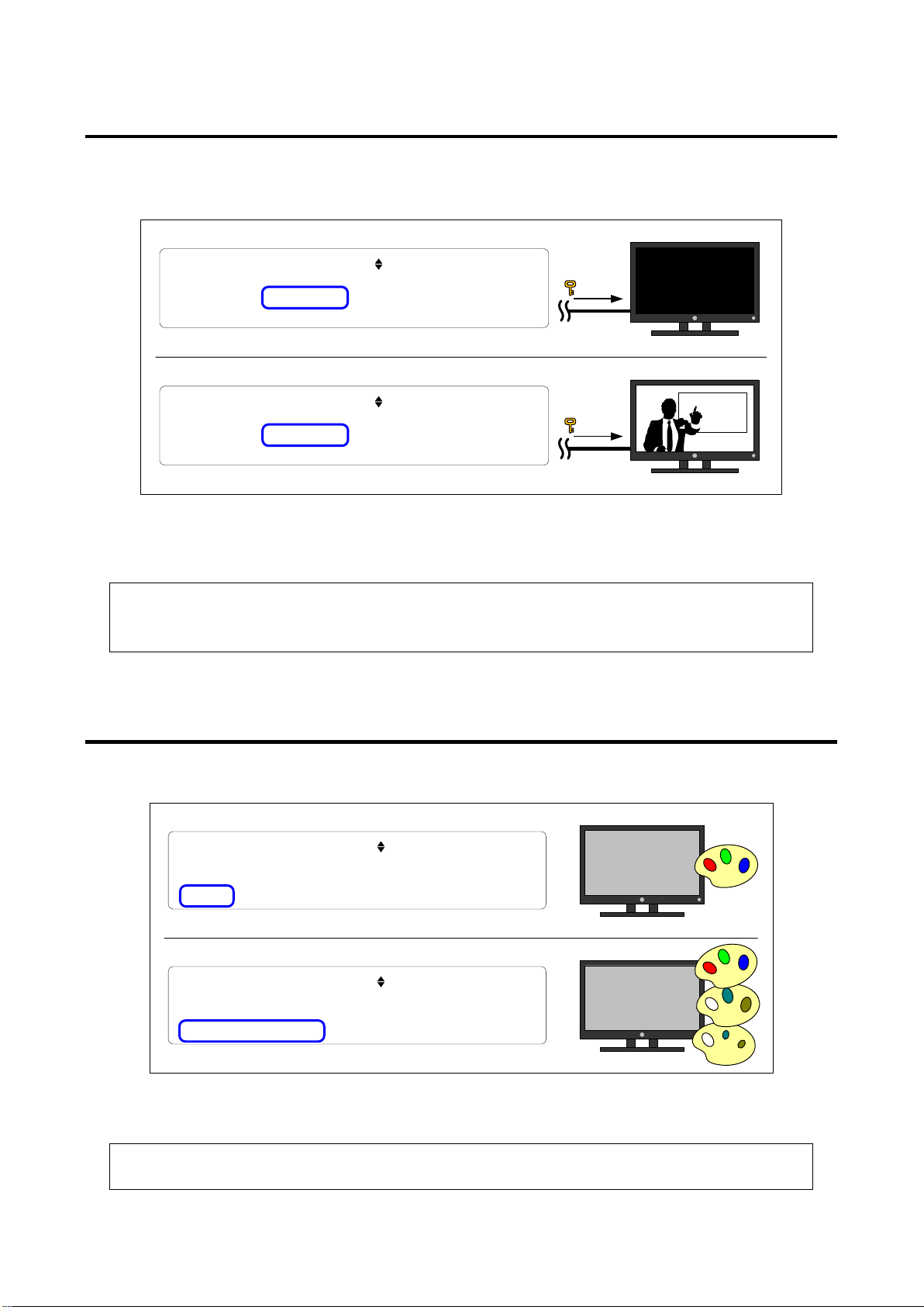
7.2.3 HDCP (copyright protection) supported/not supported
If the sink device does not support HDCP (copyright protection), “HDCP:NG” is displayed while “HDCP:OK” is
displayed for device that supports HDCP. Sink devices that do not support HDCP cannot display or output
audio video and audio having HDCP.
[Fig. 7.2] HDCP supported/not supported
<Recommended actions for when the image cannot be displayed on the sink device>
● Check the power supply, input switching (if there are some inputs), and operation using test
patterns (P.39) of the sink device.
7.2.4 Supported color space
RGB4:4:4: “R444”, YCbCr4:2:2: “Y422”, YCbCr4:4:4: “Y444”
<Recommended actions for when the image is not display with correct colors>
[Fig. 7.3] Supported color space
Sink device: Check the operation using test patterns (P.39)
36
Page 37
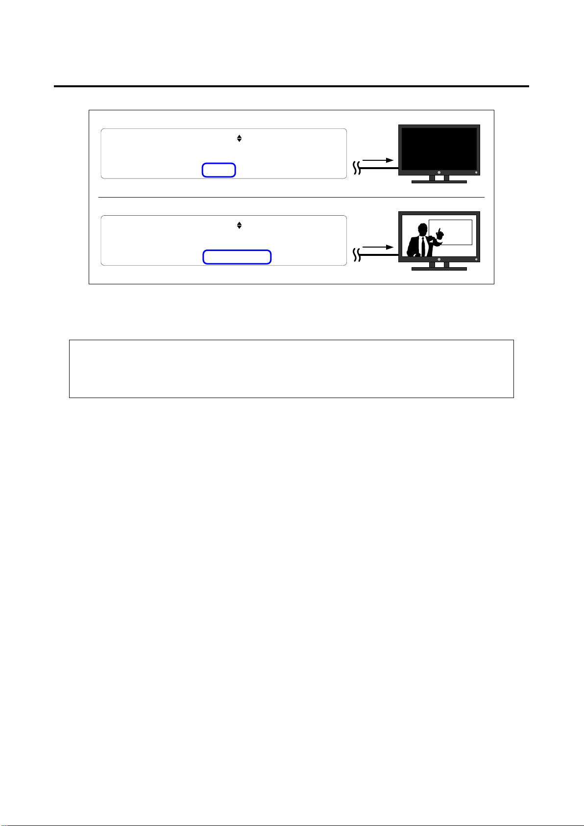
7.2.5 Supported color depth (Deep Color)
TOP >
SINK STATE [
1 /
4
] SUMMARY 1
IDK 001H
DVI
& HDMI
, HDCP: OK, NOT REPEATER
R 444
/
Y 422
/ Y
444
, 8 bit
TOP > SINK STATE
[ 1
/
4 ] SUMMARY 1
IDK 001H
DVI
& HDMI, HDCP: OK, NOT REPEATER
R
444/
Y
422/
Y 444, 8 / 10/ 12bit
12
bit
12
bit
12 bit (36 bit/pixel): “12bit” 10 bit (30 bit/pixel): “10bit” 8 bit (24 bit/pixel): “8bit”
[Fig. 7.4] Supported color depth
GF-100 User’s Guide
<Recommended actions for when the image cannot be displayed on the sink device>
● Sink device: Check the power supply, input switching (if there are some inputs), and operation
using test patterns (P.39).
● Source device: Check the presence or absence of output signals (P.21) and color depth of output
signals (P.24).
37
Page 38
GF-100 User’s Guide
TOP >
SINK STATE [ 2 / 4 ] SUMMARY
2 TIMING
PREFER: 1920x 1200p ,
59.
95
Hz,
16:
10
NATIV1 : 1920x
1080
p ,
59.
94
/ 60
Hz
, 16
: 9
NATIV2 : -
TOP > SINK STATE [
2
/ 4
] SUMMARY 2 TIMING
PREFER:
1920
x 1200
p ,
59
. 95Hz, 16: 10
NATIV1
: 1920
x
1080p , 59. 94/ 60Hz, 16: 9
NATIV
2
: -
Preferred resolution
1920
x1200
Native resolution
1920x
1080
TOP > SINK STATE [ 3 / 4 ] SUMMARY 3 SPEAK
[ --- --- FL ---][--- --][--- FR --- ---]
[ --] [---]
[ -- ---] [--] [--- --]
FLW
FL FLC
FC
FRC
FR
LFE
TC
RC
RLCRL
RR
FRONT
REAR
FRW
RRC
RL
Rear Left
FLW
Front Left Wide
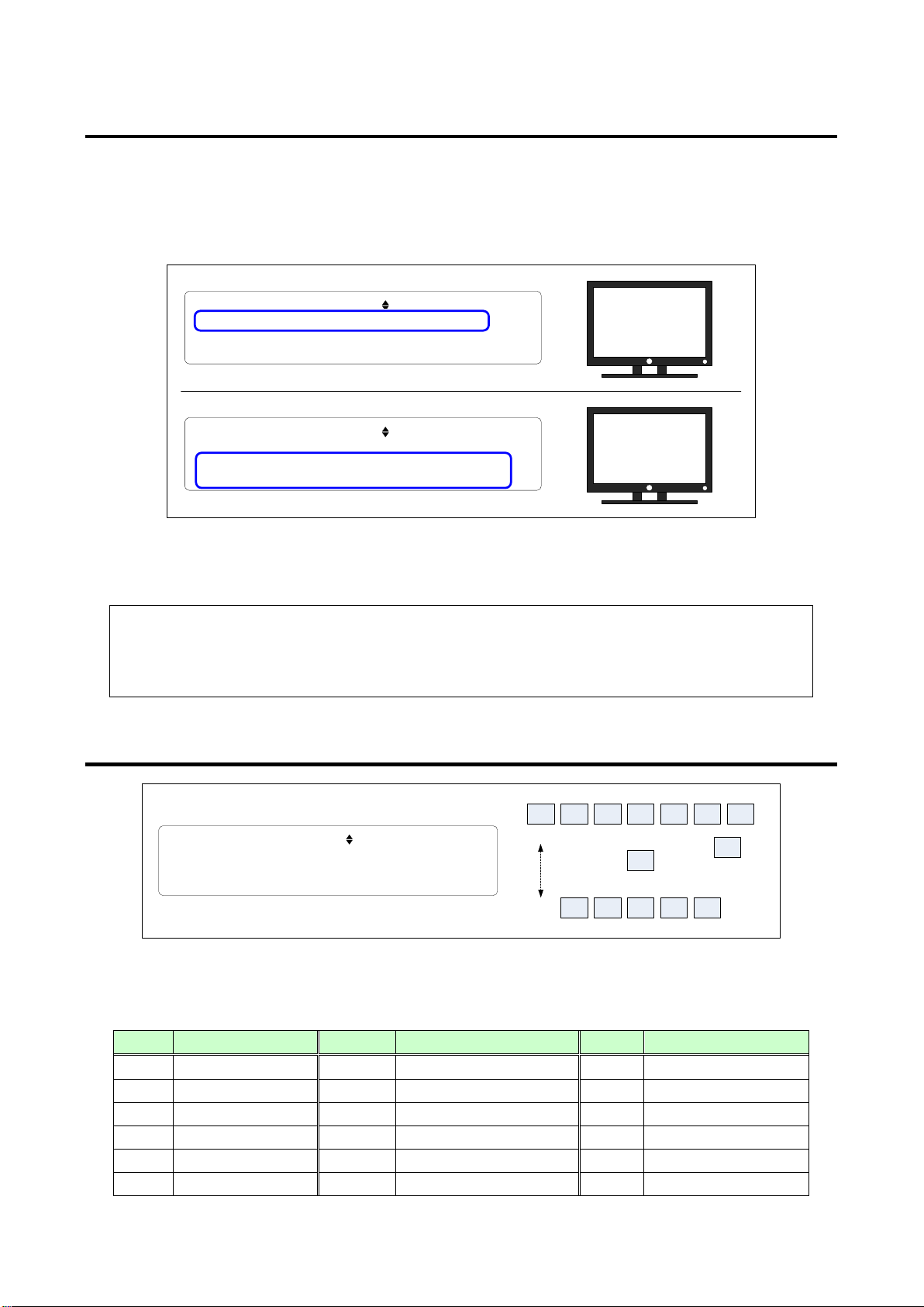
7.2.6 Preferred/native resolution
“PREFER”: resolution recommended by the manufacturer of the sink device
“NATIV1” and “NATIV2”: native resolution (the maximum resolution of sink devices’ pixel)
For other supported resolutions, see “7.2.8 Detailed EDID(P.39)”.
Note: Handling preferred and native resolutions differs by manufacturers. The preferred resolution is
sometimes higher than the native resolution due to scaling.
[Fig. 7.5] Preferred/native resolution
<Recommended actions for when the image cannot be displayed on the sink device>
● Sink device: Check the power supply, input switching (if there are some inputs), and operation
using test patterns (P.39).
● Source device: Check the presence or absence of output signals (P.21) and output resolution
(P.21).
7.2.7 Configuration of supported speakers
[Fig. 7.6] Speaker configuration
Name Position Name Position Name Position
FL Front Left RC Rear Center FRW Front Right Wide
FC Front Center RR Rear Right FLH Front Left High
FR Front Right RLC Rear Left Center FCH Front Center High
FLC Front Left Center RRC Rear Right Center FRH Front Right High
FRC Front Right Center LFE Low Frequency Effect TC Top Center
38
[Table 7.1] Speaker position
Page 39
GF-100 User’s Guide
TOP > SINK STATE [4/ 4 ] SINK EDID
EDID BLOCK = BASIC(USED)
PUSH "SET" TO ENTER
Detailed EDID information
・Manufacturer
・Supported resolution
・Supported audio format
etc.
GF-100
Sink device
Sink test connector
7.2.8 Detailed EDID information
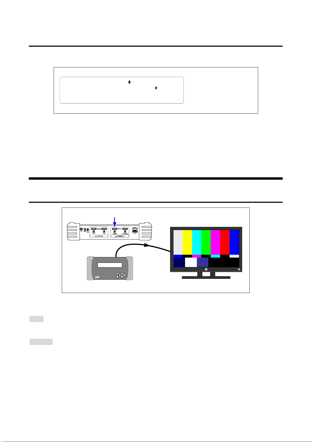
Displaying the detailed EDID information of the sink device, such as manufacturer, supported resolution and
audio format.
[Fig. 7.7] Detailed EDID information
<Reference>
E-EDID: VESA Enhanced Extended Display Identification Data Standard Release A, Revision 2
CEA-861: CEA Standard A DTV Profile for Uncompressed High Speed Digital Interfaces
7.3 Test pattern/tone
7.3.1 Outputting test pattern/tone
[Fig. 7.8] Outputting test pattern
Menu
TOP → TEST PATTERN → OUTPUT
Set value
OFF: Outputting the signals of the source test connector to the sink test connector
ON: Outputting test pattern/tone [Default]
39
Page 40
GF-100 User’s Guide
75% COLOR BAR
EIA COLOR BAR SMPTE COLOR BAR
H GRAY SCALE 10 STEP
H GRAY SCALE
5x
5 CROSS HATCH
20x20 CROSS HATCH
VERTICAL STRIPES HORIZONTAL STRIPES
7
x7 CROSS HATCH
4x4
CROSS HATCH
V GRAY SCALE 10 STEP
V GRAY SCALE
6x6 CROSS HATCH
100% WHITE RASTER 75% GRAY RASTER 50% GRAY RASTER
25% GRAY RASTER BLACK RASTER RED RASTER GREEN RASTER BLUE RASTER
V GRAY SCALE 32 STEP
H GRAY SCALE 32 STEP
MULTI SET 10x
10 MULTI SET 12x12 MULTI SET 14x
14
MULTI SET 20x20
MULTI SET 8x
8
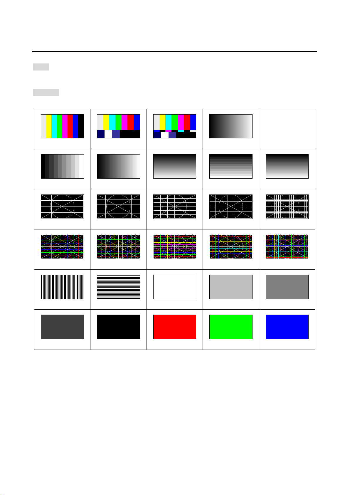
7.3.2 Selecting test pattern
Menu
TOP → TEST PATTERN → CONTENTS
Set value
[Default: SMPTE COLOR BAR]
[Fig. 7.9] Test patterns
40
Page 41
7.3.3 Test pattern resolution
PC resolution
TV resolution
VGA
640x 480
60 Hz
4:3
480i
720x 480
29.97 Hz
4:3
SVGA
800x 600
60 Hz
4:3
480p
720x 480
59.94 Hz
4:3
XGA
1024x 768
60 Hz
4:3
576i
720x 576
25 Hz
4:3
OV-MP
1024x 768
59.94 Hz
4:3
576p
720x 576
50 Hz
4:3
WXGA-1
1280x 768
60 Hz
5:3
720p
1280x 720
50 Hz
16:9
WXGA-2
1280x 800
60 Hz
16:10
720p
1280x 720
59.94 Hz
16:9
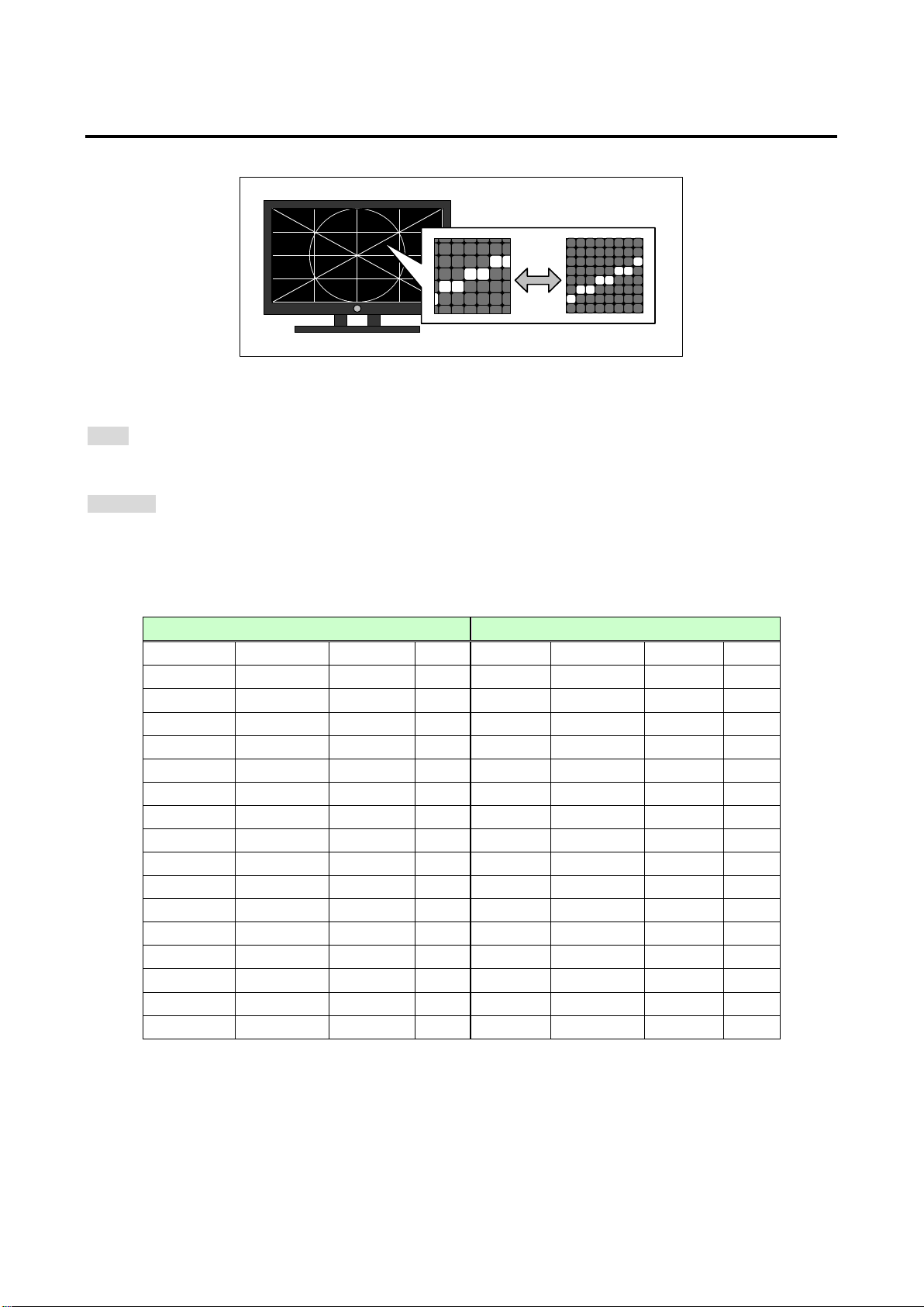
[Fig. 7.10] Test pattern resolution
Menu
TOP → TEST PATTERN → RESOLUTION
Set value
AUTO: Automatic [Default]
[Table 7.3.3]: Manual
[Table 7.2] Test pattern resolution
GF-100 User’s Guide
Quad-VGA 1280x 960 60 Hz 4:3 720p 1280x 720 60 Hz 16:9
SXGA 1280x1024 60 Hz 5:4 1080i 1920x1080 25 Hz 16:9
WXGA-3 1360x 768 60 Hz 16:9 1080i 1920x1080 29.97 Hz 16:9
WXGA-4 1366x 768 60 Hz 16:9 1080i 1920x1080 30 Hz 16:9
SXGA+ 1400x1050 60 Hz 4:3 1080p 1920x1080 50 Hz 16:9
WXGA+ 1440x 900 60 Hz 16:10 1080p 1920x1080 59.94 Hz 16:9
WXGA++ 1600x 900 60 Hz 16:9 1080p 1920x1080 60 Hz 16:9
UXGA 1600x1200 60 Hz 4:3
WSXGA+ 1680x1050 60 Hz 16:10
WUXGA 1920x1200 60 Hz 16:10
QWXGA 2048x1152 60 Hz 16:9
WUXGA/QWXGA: Reduced Blanking
41
Page 42

GF-100 User’s Guide
7.3.4 Test pattern HDCP
Menu
TOP → TEST PATTERN → HDCP OUT
Set value
AUTO: automatic [Default]
OFF: without HDCP
ON: with HDCP
7.3.5 Test pattern format/color space
Menu
TOP → TEST PATTERN → FORMAT
Set value
AUTO: automatic [Default]
DVI
HDMI RGB
HDMI YCbCr4:2:2
HDMI YCbCr4:4:4
7.3.6 Test pattern color depth
Menu
TOP → TEST PATTERN → COLOR DEPTH
Set value
AUTO: automatic [Default]
8 bit: 24 bit/pix el (8 bit/component )
10 bit: 30 bit/pixel (10 bit/component )
12 bit: 36 bit/pixel (12 bit/component )
Note: If “7.3.5 Test pattern format/color space(P.42)” is set to “DVI”, “8 bit” will be applied automatically.
42
Page 43
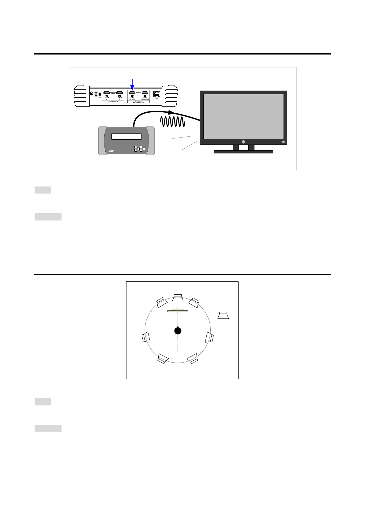
7.3.7 Selecting test tone
Sink test connector
GF-100
Sink device
Beep
CH4
CH1 CH2
CH3
CH5 CH6
CH7 CH8
[Fig. 7.11] Test tone
Menu
TOP → TEST PATTERN → TEST TONE
Set value
MUTE, 400Hz(CH3=30Hz), 400Hz(CH3=80Hz)
1000Hz(CH3=30Hz), 1000Hz(CH3=80Hz) [Default]
GF-100 User’s Guide
7.3.8 Test tone: output channel
[Fig. 7.12] Speaker configuration example
Menu
TOP → TEST PATTERN → TONE CH
Set value
CH1-CH8, CH1-CH2 [Default]
CH1, CH2, CH3, CH4, CH5, CH6, CH7, CH8
43
Page 44

GF-100 User’s Guide
7.3.9 Test tone: standard level
Menu
TOP → TEST PATTERN → TONE LEVEL
Set value
-20 dBFS: Standard signal level [Default]
0 dBFS: Full-scale level
44
Page 45
GF-100 User’s Guide
8 Monitoring DDC
8.1 Outline
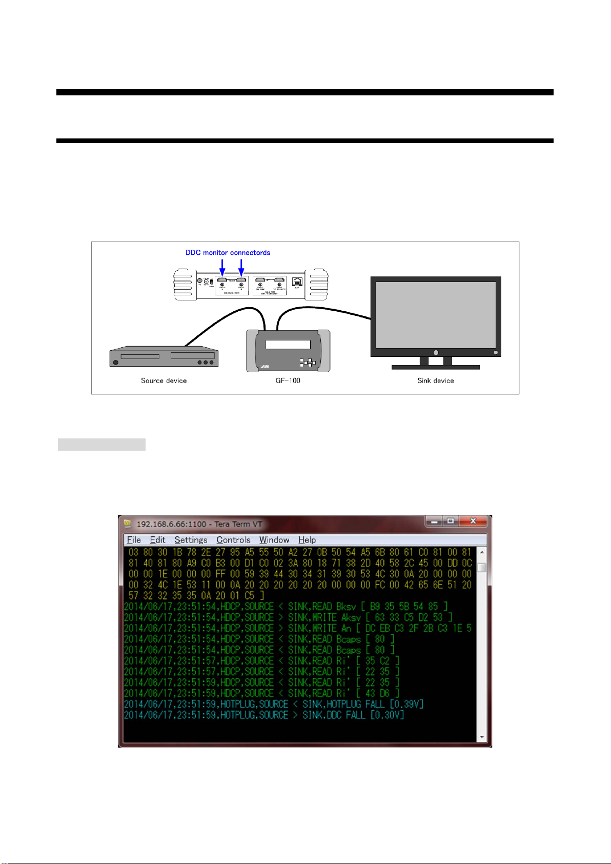
DDC communication between the source de vice and sink device (hot plug voltage, DDC voltage, EDID, and
HDCP) can be output to a browser or TCP/IP port “1100”.
Connect the sink device and source device to the DDC monitor connectors (in the example below, the source
device is connected to connector A, but it can be connected to the connector B as well).
[Fig. 8.1] Connection for monitoring DDC
Terminal software
The communication contents are output to TCP/IP port “1100”.
Hot plug/DDC voltage, EDID, and HDCP are displayed in light blue, yellow, and green,
respectively.(P.47)
[Fig. 8.2] Terminal software for monitoring DDC
45
Page 46
GF-100 User’s Guide
TOP > DDC MONITOR [ 1 /
3 ] STATUS
HP : 4 . 84
V EDID :
DDC:
5 . 01
V HDCP :
OTHERS:
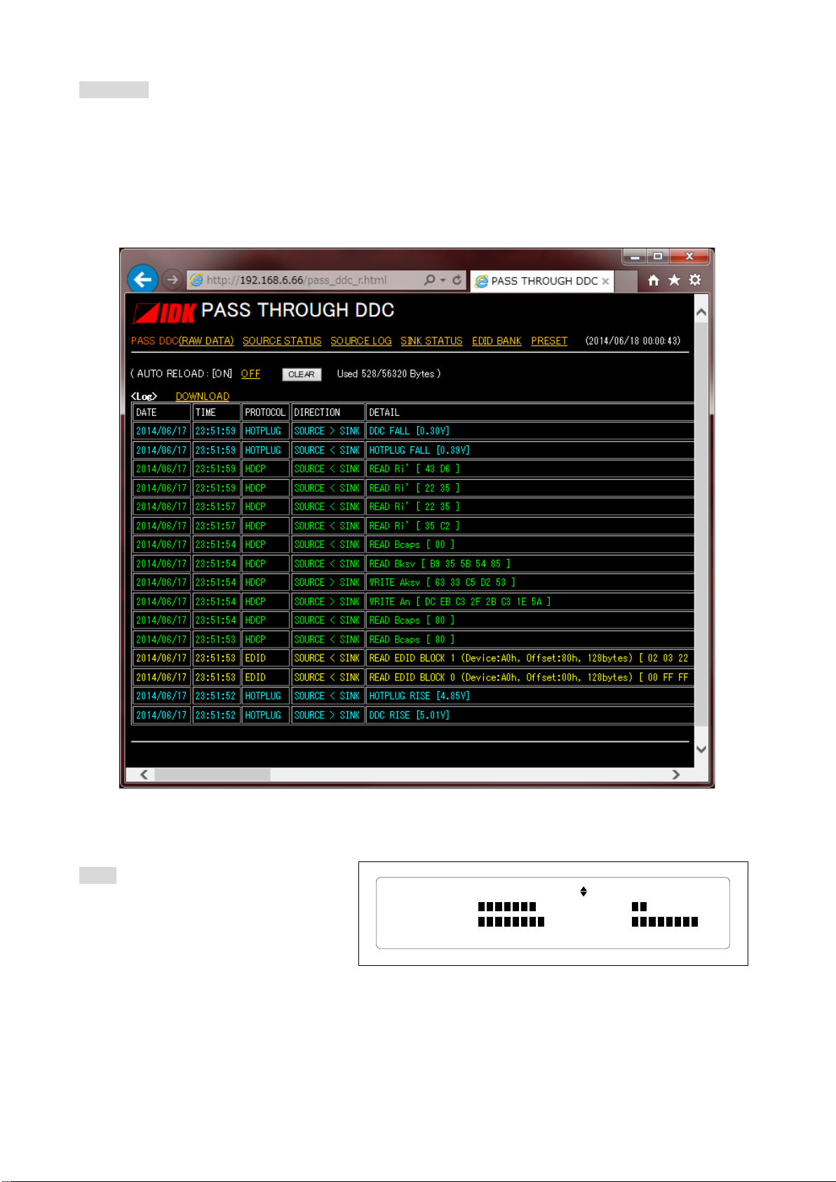
WEB page
http://The GF-100’s IP address/pass_ddc_r.html : Displays the protocol of EDID and HDCP
http://The GF-100’s IP address /pass_ddc_raw_r.html : Displays the DDC communication data
● The history data of the DDC monitoring data is kept even after turning off the GF-100.
● When no space is available in the save area of communication history (56,320 byte), from the oldest data
will be deleted.
Menu
TOP → DDC MONITOR → STATUS
The simplified communication status is
displayed.
[Fig. 8.4] Simplified display
46
[Fig. 8.3] WEB page for monitoring DDC
Page 47

8.2 Recording item
The recording of DDC communication items
Menu
TOP → DDC MONITOR → HP/DDC LOG: Hot plug/DDC voltage
TOP → DDC MONITOR → EDID LOG: EDID
TOP → DDC MONITOR → HDCP LOG: HDCP
TOP → DDC MONITOR → OTHERS LOG: other protocols
Set value
OFF: Not recorded
ON: Recorded [Default]
8.3 Be e p sound
You can enable or disable the beep sound when a DDC communication is detected.
If “10.5.2 Beep sound (P.58)” is set to “OFF”, it does not sound.
Menu
TOP → DDC MONITOR → BUZZER
Set value
OFFON
[Default]
GF-100 User’s Guide
8.4 DDC Escape sequence
Adding letter color codes to the terminal software
Menu
TOP → DDC MONITOR → ESCA PE C O DE
Set value
DISABLE
ENABLE : Hot plug/DDC voltage, EDID, and HDCP are displayed in light blue, yellow, and green,
respectively [Default]
47
Page 48
GF-100 User’s Guide
CableGF
-
100
Sink test
connector
Source test
connector
Test signals
Transmission path
GF
-100 GF-
100
Sink test
connector
Source test
connector
Test signal
① Press the “SET
” key
(Starts to send
)
② Press the “SET” key
(Starts to receive)
③ Displays result
DDCPW
DATA0~2 (BER)
GND
③ Displays result
HP
SCL/SDA
GND
9 Cable /transmission path test
9.1 Outline
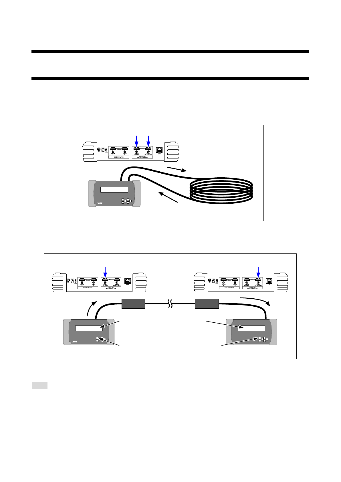
The GF-100 outputs the test signals in order to measure the quality (bit color) of the cable/transmission path.
The test signals consist of random data and data that is under tougher condition (the hardware of the cable
and its transmission).
The resolution and color depth of the test signals can be selected.
[Fig. 9.1] Connection for Cable/transmission path test
With two GF-100 units, the transmission path test between two distant sites can be performed.
[Fig. 9.2] Connection between two distance sites
Menu
TOP → CABLE TEST →
The cable/transmission path test can be started by pressing the “SET” key while the CABLE TEST menu
is displayed after devices are connected to GF-100.
Note: The GF-100 is a simplified analyzer for field supports of AV systems. Please note that it does not
provide calibrations.
48
Page 49
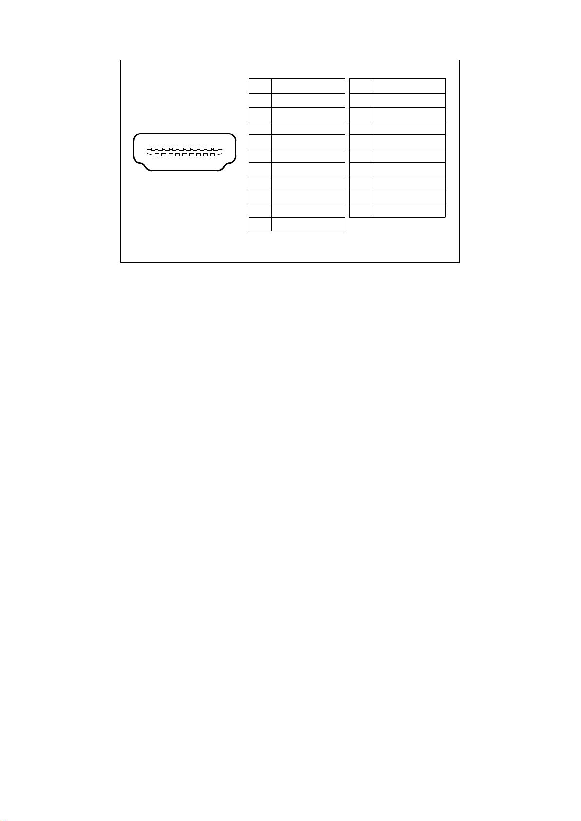
TMDS Data2+
TMDS Data2TMDS Data1 Shield
TMDS Data0+
TMDS Data0TMDS Clock Shield
CEC
DDC/CEC Ground
Hot Plug Detect
TMDS Data2 Shield
TMDS Data1+
TMDS Data1TMDS Data0 Shield
TMDS Clock+
TMDS ClockUtility
SDA
DDC PW(+5V Power)
SCL
Signal SignalPin Pin
1
3
5
7
9
11
13
15
17
19
2
4
6
8
10
12
14
16
18
1113151719 13579
12141618 246810
Tests for CEC and Utility pins are not supported.
GF-100 User’s Guide
[Fig. 9.3] Pin assignments (GF-100 side)
49
Page 50
GF-100 User’s Guide
TOP > CABLE TEST [ 3 / 3 ] START:"SET" KEY
BER = --------- --/ -- bit
DDCPW: -- HP: -- SCL/ SDA: -- GND: - ERR D0 : - D 1 : - D 2 : -
①
TOP > CABLE TEST [ 3 / 3 ] START:"ESC" KEY
DISCONNECTED... RX: NO SIGNAL
DDCPW: -- HP: -- SCL/ SDA: -- GND: - ERR D0 : - D 1 : - D 2 : -
②
Test signal cannot
be received.
TOP
> CABLE TEST
[ 3 / 3
] START:"
ESC" KEY
WAITING... RX
: 1920x
1080p @ 59.
95Hz
DDCPW: OK HP
: OK SCL/
SDA: OK GND
: OK
ERR D0
: - D 1 : -
D 2 :
-
③
Test signal
TOP
> CABLE TEST [ 3
/ 3 ]
START:"ESC"
KEY
SYNC FAILED.(D
0 / D 1 / D 2
/ CLK ERROR)
DDCPW: OK HP: OK SCL/
SDA:
OK GND: OK
ERR D
0 : - D 1 :
- D 2
: -
Synchronization
failed
9.2 O pe ration and display example
Example of a cable/transmission path test
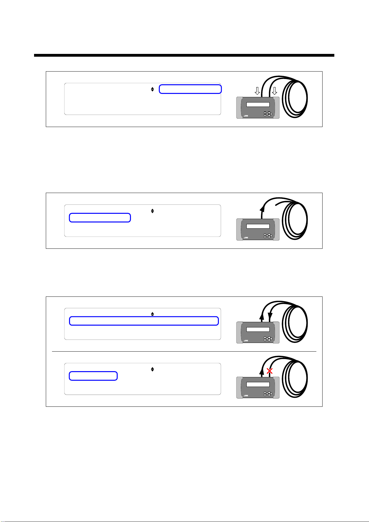
[Fig. 9.4] Starting measurement
The cable/transmission path test can be started by pressing the “SET” key while any of the cable test menus
is displayed.
If “9.7 Starting measurement (P54)” is set to “AUTO”, the measurement can be started by unplugging and
plugging the cable while the cable test status is displayed (TOP→CABLE TEST [3/3]).
[Fig. 9.5] Signals are not detected
If the test signals cannot be received due to the cable disconnection or TMDS Data/TMDS Clock or if the
resolutions or color depth of the received and test signals do not match, “DISCONNECTED...” is displayed.
[Fig. 9.6] Waiting for signal stability/Synchronization failed
When the GF-100 detects received signals, it displays “WAITING…” and waits until the signals become
stabilized.
You can change the waiting time in “9.6 Waiting time for starting pixel scan (P54)”.
If the bit error cannot be measured due to signal deterioration or if there is a device that makes the resolution
unstable during transmission, the GF-100 displays “SYNC FAILED” and finishes the measurement.
50
Page 51
GF-100 User’s Guide
TOP > CABLE TEST [ 3 / 3 ] START:"ESC" KEY
COMPAREING... ____________________
DDCPW: OK HP: OK SCL/ SDA: OK GND: OK
ERR D0 : 0 D 1 : 0 D 2 : 0
Received windowSent window
Compare
④
TOP
> CABLE TEST [ 3
/ 3 ] START:"SET" KEY
BER
= 0
% 0 / 2488320 bit
DDCPW: OK HP: OK SCL/ SDA
:
OK GND:
OK
ERR D
0 :
0 D
1
: 0
D 2 : 0
⑤
Total bit error rate
Total number of bit errors/The number of test bits
The number of bit errors in TMDS Data 2
The number of bit errors in TMDS Data 1
The number of bit errors in TMDS Data 0
TOP
> CABLE TEST [ 3 / 3 ] START
:"SET"
KEY
BER = 0 % 0
/ 2488320 bit
DDCPW:
OK HP: OK SCL/ SDA: OK GND: OK
ERR D0 : 0 D 1 : 0 D 2 : 0
1113151719
13
57
9
121416
18 246810
11
13
1517 135
79
1214 246810
TMDS Data 2
TMDS Data 1
TMDS Data
0
1816
19
SDA
DDC PW (+5
V Power)
HP (
Hot Plug Detect
)
SCL
Socket side
Result of signal conduction
CEC and Utility pins are not supported.
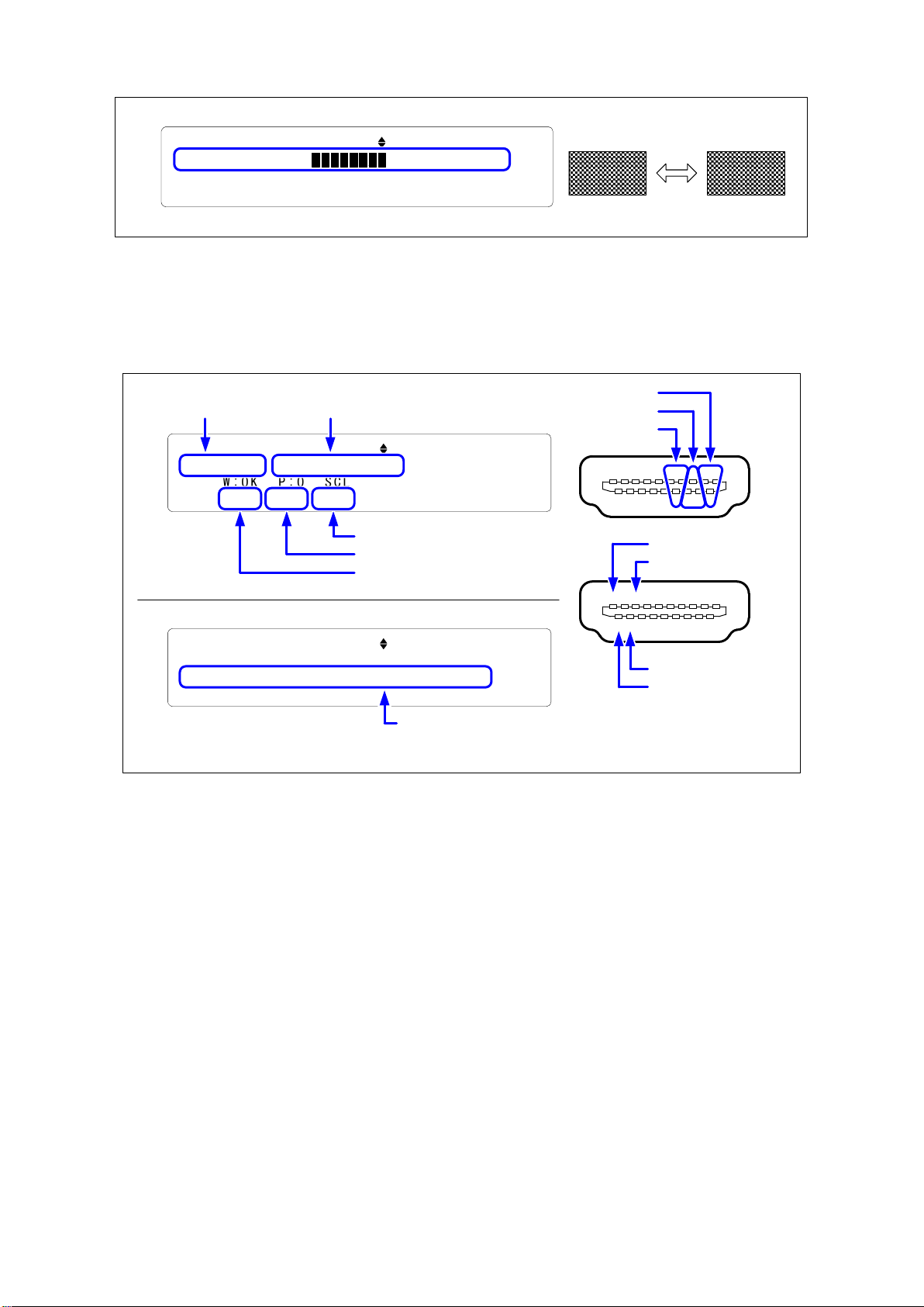
[Fig. 9.7] Signals comparison
The GF-100 displays “COMPAREING...” and measures the bit error by comparing the test signals and
received signals.
You can set the amount of those signals for the comparison in “9.4 The amount of test data (P53)”.
When the measurement of the bit error is completed, the result is displayed.
If the total number of bit errors is “0” and all signal conductions are “OK”, the cable is normal.
Even if the bit error is not “0”, video m a y be displa yed cor rec tl y, depending on the equalizer performance of
the sink device and the output signal quality of the source device.
Table 9.2 on the next page shows the measurement results of IDK’s cables as examples.
For IDK’s 20 m/65.62 ft. or shorter cables, the acceptance criteria is fixed at “0”. For long cables, the criteria
vary depending on the usage environment.
Note: Please do not apply an extra force to the connector at the time of connection; otherwise, the
measurement may not be performed correctly.
[Fig. 9.8] Result
51
Page 52
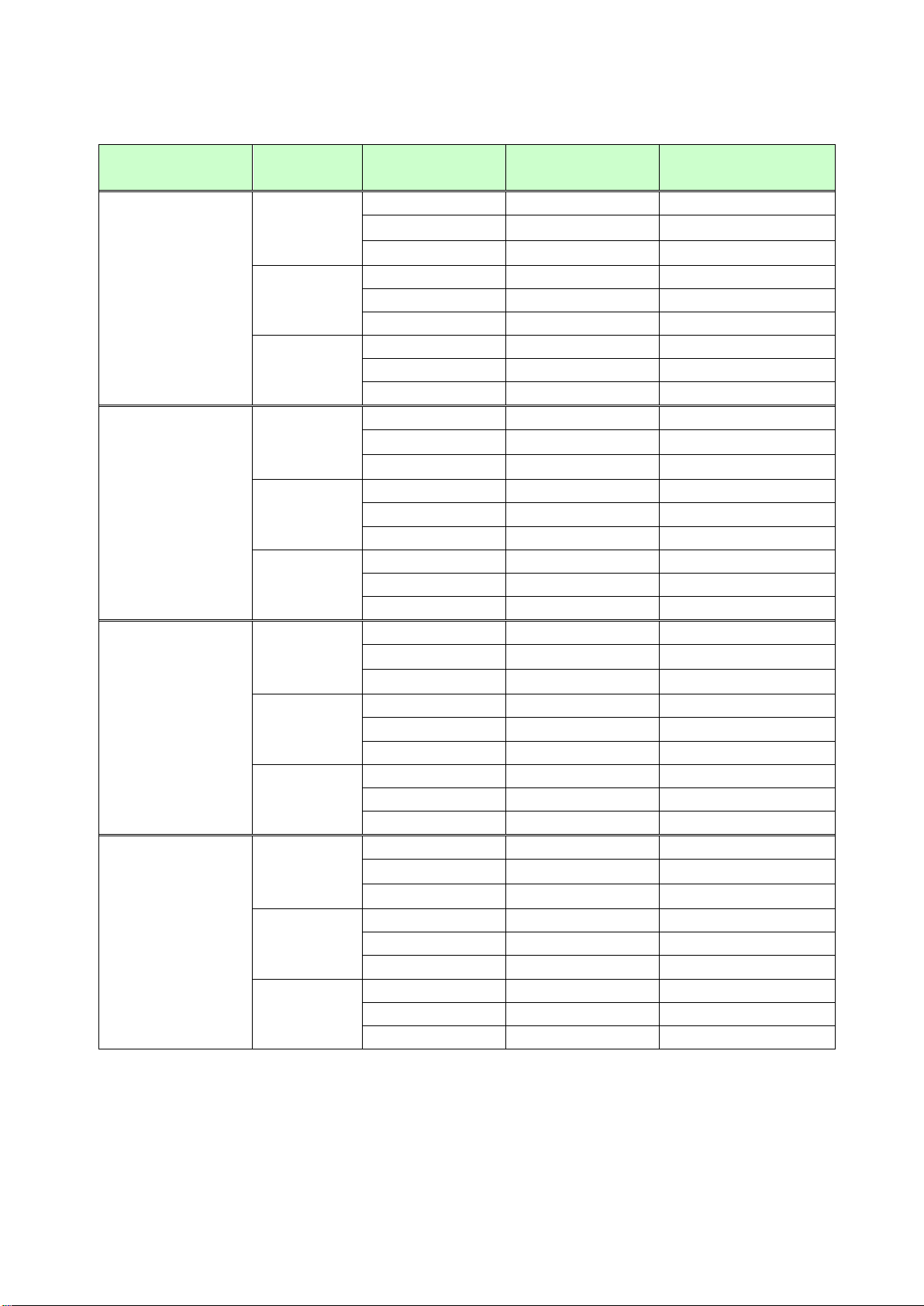
GF-100 User’s Guide
errors/Result
8
8294400
0
10
10368000
0
12
12441600
0
8
22118400
0
10
27648000
0
10
62208000
SYNC FAILED
12
74649600
SYNC FAILED
8
8294400
2761826
10
10368000
SYNC FAILED
12
12441600
SYNC FAILED
8
22118400
SYNC FAILED
10
27648000
SYNC FAILED
12
33177600
SYNC FAILED
8
49766400
DISCONNECTED
12
74649600
0
[Table 9.1] Measurement results (example)
Cable Resolution Color depth [bit] Number of test bits
480p
20 m or shorter
(without equalizer)
30 m
(without equalizer)
720p
1080p
480p
720p
1080p
12 33177600 0
8 49766400 0
10 62208000 0
12 74649600 0
8 8294400 0
10 10368000 0
12 12441600 1290
8 22118400 6
10 27648000 19
12 33177600 30884
8 49766400 0
Number of bit
480p
50 m
(without equalizer)
30 m or shorter
(with equalizer)
720p
1080p
480p
720p
1080p
10 62208000 DISCONNECTED
12 74649600 DISCONNECTED
8 8294400 0
10 10368000 0
12 12441600 0
8 22118400 0
10 27648000 0
12 33177600 0
8 49766400 0
10 62208000 0
52
Page 53
9.3 Test signals resolution
Data comparing time
Amount of test data: 5%
Amount of test data: 100%
Menu
TOP → CABLE TEST → RESOL.
Press the “SET” key to start the cable/transmission path test.
Set value
[Default: 1080p @59.94H z]
[Table 9.2] TMDS clock of test signals
GF-100 User’s Guide
Set value Resolution
8bit color 10bit color 12bit color
480p @59.94Hz 720x 480 27.00 MH z 33.75 MHz 40.50 MHz
720p @59.94Hz 1280x 720 74.18 MHz 92.72 MHz 111.26 MHz
1080p @59.94Hz 1920x1080 148.35 MHz 185.44 MHz 222.53 MHz
TMDS clock
9.4 The a m ount of test data
You can set the amount of the data which is compared (percentage of data amount in one frame).
Menu
TOP → CABLE TEST → AMOUNT
Press the “SET” key to start the cable/transmission path test.
Set value
5% to 100% [Default: 5%]
[Table 9.4] Data comparing time
Resolution
480p @59.94Hz 0.3 sec. 6.5 sec.
720p @59.94Hz 0.8 sec. 16.2 sec.
1080p @59.94Hz 1.8 sec. 35.8 sec.
Note: Time to detect test signals and waiting time for starting pixel scan are not included.
9.5 Test signals color depth
Menu
TOP → CABLE TEST → COL.DEPTH
Press the “SET” key to start the cable/transmission path test.
Set value
8bit: 24 bit/pixel (8 bit/component) [Default]
10bit: 30 bit/pix el (10 bit/component)
12bit: 36 bit/pix el (12 bit/component)
53
Page 54

GF-100 User’s Guide
9.6 Waiting time for starting pixel scan
You can set the waiting time from synchronous signal detection to starting pixel scan
For transmission path on which noise or a black frame appears, the measurement may not be performed
correctly immediatel y after video signals are connected. In this case, delay the starting time of pixel scan.
Menu
TOP → CABLE TEST → CAPT.WAIT (capture wait)
Press the “SET” key to start the cable/transmission path test.
Set value
500ms to 30000ms [Default: 2000 ms.]
9.7 S t a rt ing measurement
Menu
TOP → CABLE TEST → START
Press the “SET” key to start the cable/transmission path test.
Set value
MANUAL : Starts the test by pressing the “SET” key. [Default]
AUTO: Starts the test by pressing the “SET” key or unplug and plug the cable while the cable test status
is displayed (TOP→CABLE TEST [3/3]). Use this mode to perform the cable test repeatedly.
Note: If DDCPW(+5V) is disconnected, the GF-100 tries to restart the measurement repeatedly.
Related information
“5.2 Setting/canceling key lock(P.18)” and “10.5.3 Resume (P58)”
54
Page 55

GF-100 User’s Guide
10 Setting GF-100
10.1 Source test connector
10.1.1 Requesting input signals
If you change the EDID setting of the GF-100 or restart it while the connected source device is turned on,
some source devices stop outputting signals. In such a case, use this menu to request the source device to
output signals.
Menu
TOP → SETTINGS → VIDEO INPUT → SIGNAL REQUEST
Set value
OFF: The GF-100 does not request to output signals even if the source device stops outputting signals.
1 sec to 30 sec: The GF-100 requests to output signals after the set time if the source device stops
outputting signals. [Default: 20 sec]
10.1.2 Input DC balance
Set this menu if video of the source device cannot be displayed.
Menu
TOP → SETTINGS → VIDEO INPUT → RECV OFFSET
Set value
DISABLE [Default]
ENABLE
10.1.3 HDCP enabled/disabled
Menu
TOP → SETTINGS → VIDEO INPUT → HDCP INPUT
Set value
ACTIVE: [Default]
INACTIVE
55
Page 56

GF-100 User’s Guide
10.1.4 Input bus reset time
If the GF-100 detects an error in input signals, it disconnects the internal input bus for the set time in order to
resolve the problem.
Menu
TOP → SETTINGS → VIDEO INPUT → BUS RESET TIME
Set value
OFF
1ms to 800ms: Input bus reset time [Default: 200 ms]
10.2 Sink test connector
10.2.1 Outputting signals forcibly
Menu
TOP → SETTINGS → VIDEO OUTPUT → FORCED OUT
Set value
OFF [Default]
ON: Signals are output forcibly even if the GF-100 cannot detect the sink device.
10.3 System Clock
10.3.1 Setting current time of the GF-100
Menu
TOP → SETTINGS → CLOCK
Press the “SET” key to set the setting.
56
Page 57

10.4 LAN
10.4.1 IP address
Menu
TOP → SETTINGS → LAN → IP ADDRESS
[Default 192.168.001.199]
10.4.2 Default gateway
Menu
TOP → SETTINGS → LAN → GATEWAY ADDR.
[Default 192.168.001.001]
GF-100 User’s Guide
10.4.3 Subnet mask
Menu
TOP → SETTINGS → LAN → SUBNET MASK
[Default 255.255.255.000]
10.4.4 Displaying MAC address
Menu
TOP → SETTINGS → LAN → MAC ADDRESS
57
Page 58

GF-100 User’s Guide
10.5 Others
10.5.1 Time for turning off backlight
When any key operation is not performed for the set time, the backlight will be turned off.
Menu
TOP → SETTINGS → OTHERS → BACKLIGHT OFF
Set value
DISABLE: The backlight is always turned on [Default]
1 sec to 600 sec: The backlight is turned off after the set time.
10.5.2 Beep sound
A beep that sounds every time a key is pressed.
Menu
TOP → SETTINGS → OTHERS → BUZZER
Set value
OFF
ON [Default]
10.5.3 Resume
Menu
TOP → SETTINGS → OTHERS → RESUME
Set value
OFF: The top menu is displayed at start-up.
ON: Displays the menu that was shown at the time of turning off last time. [Default]
5 min to 120 weeks: Displays t he top menu af ter the set tim e pass es. In other cas es, displays the menu
that was shown at the time of turning off last time.
10.5.4 Versions
Menu
TOP → SETTINGS → OTHERS → FIRM VER.: Firmware version
TOP → SETTINGS → OTHERS → BOAD VER.: Board version
TOP → SETTINGS → OTHERS → FPGA VER. : FPGA version
58
Page 59
GF-100 User’s Guide
SMPTE COLOR
11 Setting list
Setting item Page Menu Set value Default
Key lock P.18 - OFF, ON OFF
Beep for source P.28 SETTINGS → SOURCE LOG → BUZZER OFF, ON OFF
Source status
Escape sequence
Wait time for detecting source
status
EDID output mode P.30 EDID OUT → EDID MODE
Resolution of GF-100 original
EDID
Color depth of GF-100 original
EDID
The number of audio channels
of GF-100 original EDID
Audio format of GF-100
original EDID
Test pattern/tone P.39 TEST PATTERN → OUTPUT OFF, ON ON
Selecting test pattern P.40 TEST PATTERN → CONTENTS
Test pattern resolution P.41 TEST PATTERN → RESOLUTION
Test pattern HDCP P.42 TEST PATTERN → HDCP OUT AUTO, OFF, ON AUTO
Test pattern format/color
space
Test pattern color depth P.42 TEST PATTERN → COLOR DEPTH AUTO, 8 bit, 10 bit, 12 bit AUTO
Selecting test tone P.43 TEST PATTERN → TEST TONE
P.28
P.28 SETTINGS → SOURCE LOG → DETECT WAIT
P.31 EDID OUT → RESOLUT ION SVGA to QWXGA 1080p
P.31 EDID OUT → COLOR DEPTH
P.32 EDID OUT → AUDIO CHANNEL 2, 2.1, 3.1, 5, 5.1, 7, 7.1CH 7.1 CH
P.33
P.42 TEST PATTERN → FORMAT
SETTINGS → SOURCE LOG → ESCAPE
CODE
EDID OUT → PCM OFF,MAX 32.0 to 192.0 kHz MAX 48.0 kHz
EDID OUT → Dolby Digital OFF, MAX 32.0 to 48.0 kHz MAX 48.0 kHz
EDID OUT → AAC OFF, MAX 32.0 to 96.0 kHz MAX 48.0 kHz
EDID OUT → Dolby Digital+ OFF, MAX 32.0 to 48.0 kHz MAX 48.0 kHz
EDID OUT → DTS OFF, MAX 32.0 to 96.0 kHz MAX 48.0 kHz
EDID OUT → DTS-HD OFF, MAX 32.0 to 192.0 kHz MAX 192.0 kHz
EDID OUT → Dolby TrueHD OFF, MAX 32.0 to 192.0 kHz MAX 96.0 kHz
DISABLE
ENABLE
NO WAIT
100ms to 10000ms
AUTO
ORIGINAL
BANK 1 to 5
24 bit
24/30 bit
24/30/36 bit
75% COLOR BAR to
BLUE RASTER
AUTO
VGA to QWXGA
[email protected]@60Hz
AUTO
DVI
HDMI RGB
HDMI YCbCr4:2:2
HDMI YCbCr4:4:4
MUTE
400Hz(CH3=30Hz)
400Hz(CH3=80Hz)
1000Hz(CH3=30Hz)
1000Hz(CH3=80Hz)
ENABLE
800ms
AUTO
24 bit
BAR
AUTO
AUTO
1000Hz
(CH3=80Hz)
59
Page 60
GF-100 User’s Guide
Setting item Page Menu Set value Default
CH1-CH8
Test tone: output channel P.43 TEST PATTERN → TONE CH
Test tone: standard level P.44 TEST PATTERN → TONE LEVEL -20 dBFS, 0 dBFS -20 dBFS
TOP → DDC MONITOR → HP/DDC LOG
Recording item P.47
Beep
DDC monitor escape
sequence
Test signals resolution
The amount of test data P.53 CABLE TEST → AMOUNT 5% to 100 % 5%
Test signals color dep th P.53 CABLE TEST → COL.DEPTH
Waiting time for starting pixel
scan
Starting measurement P.54 CABLE TEST → START MANUAL, AUTO MANUAL
Requesting input signals P.55
Input DC balance P.55 SETTINGS → VIDEO INPUT → RECV OFFSET DISABLE, ENABLE DISABLE
HDCP enabled/disabled P.55 SETTINGS → VIDEO INPUT → HDCP INPUT ACTIVE, INACTIVE ACTIVE
Input bus reset time
Outputting signals forcibly P.56 SETTINGS → VIDEO OUTPUT → FORCED OUT OFF, ON OFF
Setting current P.56 SETTINGS → CLOCK - IP P.57 SETTINGS → LAN → IP ADDRESS - 192.168.001.199
Default gateway P.57 SETTINGS → LAN → GATEWAY ADDR. - 192.168.001.001
Subnet mask P.57 SETTINGS → LAN → SUBNET MASK - 255.255.255.000
Time for turning off backlight P.58 SETTINGS → OTHERS → BACKLIGHT OFF
Beep sound P.58 SETTINGS → OTHERS → BUZZER OFF, ON ON
Resume P.58 SETTINGS → OTHERS → RESUME
Version P.58
P.47 TOP → DDC MONITOR → BUZZER OFF, ON ON
P.47 TOP → DDC MONITOR → ESCAPE CODE DISABLE, ENABLE ENABLE
P.53 CABLE TEST → RESOL.
P.54 CABLE TEST → CAPT.WAIT 500ms to 30000ms 2000 ms
P.56 SETTINGS → VIDEO INPUT → BUS RESET TIME OFF, 1ms to 800ms 200ms
TOP → DDC MONITOR → EDID LOG
TOP → DDC MONITOR → HDCP LOG
TOP → DDC MONITOR → OTHERS LOG
SETTINGS → VIDEO INPUT → SIGNAL
REQUEST
SETTINGS → OTHERS → FIRM VER. - SETTINGS → OTHERS → BOAD VER. - SETTINGS → OTHERS → FPGA VER. - -
CH1-CH2
CH1 to CH8
OFF, ON ON
8 bit
10 bit
12 bit
OFF, 1 sec to 30 sec 20 sec
DISABLE, 1 sec to 600
sec
OFF, ON
5min to 120weeks
CH1-CH2
1080p @59.94Hz
8 bit
DISABLE
ON
60
Page 61
12 Product specification
Source test and cable/transmission path test
Item Description
Video HDMI/DVI HDMI Deep Color (*)/DVI 1.0
TMDS single link, HDCP, TMDS clock: 25 MHz to 225 MHz
EDID emulation
Audio Digital audio Multi-channel linear PCM up to 8 channel
Sampling frequenc y: 32 kHz to 192 kHz, the number of quantized bits:16 bit to 24 bit
Standard level: -20 dBFS, maximum input level: 0 dBFS
Connector HDMI Type A (1 9 pin)・female
Function ・Displaying video status
Resolution, frame rate, asp ect ra ti o, HDMI/DVI, presence or absence of HDCP, color space, color depth, DDC
voltage, video timing, dot clock frequency, frame information
・Displaying audio status
Audio format, the number of channels, sampling frequency, the number of quantized bits, speaker position,
InfoFrame information
・EDID emulation (with copy function)
・Comparing sent/received signals using test signals
・Outputting source status to terminal software
・Displaying each status/source stat us using a WEB browser
Sink test and cable /tr a nsmission path test
Item Description
Video HDMI/DVI HDMI Deep Color (*)/DVI 1.0
TMDS single link, HDCP, TMDS clock: 25 MHz to 225 MHz
Test pattern
output format
Audio Digital audio Multi-channel linear PCM up to 8 channel
Test tone output
format
Connector HDMI Type A (1 9 pin)・female
Function ・Displaying sink device specification
Color space: RGB/YCbCr 4:2:2/YCbC r 4:4:4
Color depth: 24 bit, 30 bit, 36 bit Deep Color
VESA: VGA/SVGA/XGA/WXGA (1280x768)/WXGA (1280x800)/Quad-VGA/SXGA/
WXGA(1360x768)/WXGA(1366x768)/SXGA+/WXGA+/WXGA++/UXGA/WSXGA+/WUXGA/QWXGA
WUXGA/QWXGA: Reduced Blanking
SDTV/HDTV: 480i/480p/576i/576p/720p/1080i/1080p
Sampling frequenc y: 32 kHz to 192 kHz, the number of quantized bits:16 bit to 24 bit
Standard level: -20 dBFS, Output level: up to: 0 dBFS
Multi-channel linear PCM up to 8 channels
Sampling frequenc y: 48 kHz, the number of quantized bits:24 bit
Standard level: -20 dBFS, Output level: up to 0 dBFS
Supported resolution , HDMI supported/not supported, HDCP compliant/not compliant, supported color space,
supported color depth, speaker position, EDID information and other information
・Test pattern output
Color bar, gray scale, cross hatch, stripe, raster, and more
・Outputting test tone
Test audio, speaker test for each audio channel (1000 Hz,400 Hz,80 Hz,40 Hz)
・Comparing sent/received signals using test signals
・Displaying each status and downloading EDID information using a WEB browser
GF-100 User’s Guide
61
Page 62
GF-100 User’s Guide
DDC monitor
Item Description
Operation Pass through
Connector HDMI Type A (1 9 pin)・female
Function ・Displaying DDC communication contents between the source device and sink device
(Hot plug voltage, DDC voltage, EDID and HDCP)
・Outputting communication contents to terminal software
・Displaying communication histories using WEB browser
LAN
Item Description
LAN 1 port/RJ-45 10Base-T/100Base-TX (Auto Negotiation), A uto MD I/MDI-X
Others
Item Description
AC adapter Input: AC~100 V - 240 V ± 10 %,50 Hz/60 Hz ± 3 Hz
Output: DC 12 V 3 A (the AC adapter is supplied)
Power consumption About 11 W
Dimensions 260 (W)×53.5 (H)×133 (D) mm
Weight 0.9 kg/1.98 lbs.
Temperature Operating tem p era ture: 32°F to 104°F/0°C to +40°C
Storage temperature: -4°F to +176°F/-20°C to +80°C
Humidity Operating/Storage humidity: 20% to 90% (Non condensing)
Included items AC adapter (5.9 ft./1.8 m), 2P-3P conversi o n plug
* Deep color of 36 bit/pixel (12 bit/component) is supported while xvYCC, Lip Sync, 3D, ARC, HEC and CEC are not supported.
Notes:
● Specifications are subject to change without notice.
● All nominal levels are at ±5%.
62
Page 63

GF-100 User’s Guide
Headquarters
IDK Corporation
TEL: +81-46-200-0764 FAX: +81-46-200-0765
Email: [email protected] URL: http://www.idk.co.jp/en/index.html
Product information
Arvanics Corporation
TEL: +81-46-259-6920 FAX: +81-46-259-6920
Email: [email protected] URL: http://www.arvanics.com
GF-100 User’s guide
Ver.1.0.0
Issued on: 2 July 2015
7-9-1 Chuo, Yamato-shi, Kanagawa-pref.
242-0021 JAPAN
Support
3-8-3-3F Yamato H igashi, Yamato-shi, Kanagawa-pref.
242-0017 JAPAN
Information in this document is subject to change without notice.
All rights reserved. All trademarks mentioned are the property of thei r respective owners.
63
 Loading...