

IDK HDC-TH401, HDC-TH201, HDC-TH101 User Manual
HDBaseT Transmitter/Distribution Amplifier
HDC-TH401/201/101
<User Guide>
Ver.2.0.0
Thank you for choosing our product.
To ensure the best performance of this product, please read this user guide fully and carefully before
using it and keep this manual together with the product for future reference as needed.
IDK Corporation

HDC-TH401/201/101 User Guide
2
Trademarks
Blu-ray Disc and Blu-ray are trademarks of Blu-ray Disc Association.
The terms HDMI and HD MI High-Definition Mult imedia Interface, and the HDMI Logo are trademark s or
registered trademarks of HDMI Licensing Administrator, Inc. in the United States and other countries.
The terms Anti-snow and Connection Reset are registered trademarks of IDK Corporation in Japan.
All other company and product names mentioned in this manual are either registered trademarks or
trademarks of their respective owners. In this manual, the “®” or “™” marks may not be specified.

HDC-TH401/201/101 User Guide
3
Inclued Items
Before reading this manual
All rights reserved.
Some information contained in this User guide such as exact product appearance, diagrams, menu
operations, communication commands, and so on may differ depending on the product version.
This User guide is subject to change without notice. You can download the latest version from IDK’s
website at: http://www.idkav.com
Ensure all items below are included in the package.
If any items are missing or damaged, please contact IDK.
・ HDBaseT Transmitter and Splitter with HDMI Local Output (main unit)
・ Power cord, 6 ft. (1.8m) x 1
・ Cable clamp x 2
FCC STATEMENT
This equipment has been t ested and found to c omply with t he limits for a Clas s A digital device, pursuant to
part 15 of the FCC Rules. These limits are designed to provide reasonable protection against harmful
interference when the e quipm ent is oper ated in a com m ercial enviro nm ent. This equipm ent gen erates , uses ,
and can radiate radio frequency energy and, if not installed and used in accordance with the instruction
manual, may cause harmful interference to radio communications. Operation of this equipment in a residential
area is likely to cause harmf ul interf erence, i n which ca se the us er will be req uire d to c orrect the interfer ence
at his own expense.
CE MARKING
This equipment complies with the essential requirements of the relevant European health, safety and
environmental protection legislation.
WEEE MARKING
Waste Electrical and Electronic Equipment (WEEE), Directive 2002/96/EC
(This directive is only valid in the EU.)
This equipment complies with the WEEE Directive (2002/96/EC) marking requirement.
The left marking indicates that you must not discard this electrical/electronic equipment in
domestic household waste.
x 1
HDC-TH401/201/101 User Guide
4
Enforcement Symbol
Description
Indicates the presence of a hazard that may cause minor personal
Symbol
Description
Example
Hazard
disassemble
Warning
Caution
Safety Instructions
Read and understand al l safety and operating instr uctions before using this pr oduct. Follow all instructi ons
and cautions as detailed in this document.
Indicates the presence of a hazard that ma y result in death or serious
This symbol is intended to alert the user. (Warning and caution)
personal injury if the warning is ignored or the product is handled
incorrectly.
injury or property damage if the caution is ignored or the product is
handled incorrectly.
Caution
This symbol is intended to prohibit the user from specified actions.
Prohibited
This symbol is intended to instruct the user.
Instruction
Electrical
Do not
Unplug
5
Instruction
● Do not place the product upon a surface that may give way or that may become
Otherwise, it may move unexpectedly or it may fall and lead to injury.
● Installation work must be performed by professionals.
differences may cause fire or other difficulties.
● Keep out any foreign objects.
・
・
・
contact your IDK representative.
disassemble
● Do not repair, modify or disassemble.
personnel may lead to the risk of fire or electric shock. For internal inspection or repair, contact your IDK
● Do not touch the product and connected cables during electrical storms.
Instruction
● Clean the power plug regularly.
Warning
■ For lifting heavy products:
HDC-TH401/201/101 User Guide
● Lifting must be done by two or more personnel.
To avoid injury: When lifting the product, bend your knees, keep your back straight and get close to it with two or
more persons.
■ For installing and connecting products:
unstable.
Install the product in a secure and stable place to prevent it from falling and possibly causing injury.
Prohibited
Instruction
● Secure the product if installing in locations prone to vibration or movement.
The product is intended to be installed by skilled technicians. For installation, please contact a system integrator
or IDK. Improper installation may lead to the risk of fire, electric shock, injury, or property damage.
● Insert the power plug into an outlet that is unobstructed.
Unobstructed access to the plug enables unplugging the product in case of any extraordinary failure, abnormal
situation or for easy disconnection during extended periods of non-use.
● Insert the power plug into an appropriate outlet completely.
If the plug is partially inserted, arching may cause the connection to overheat, increasing the risk of electrical
shock or fire. Do not use a damaged plug or connect to a damaged outlet.
● Unplug the product from the AC power source during installation or service.
When connecting peripheral devices to this product, unplug all involved devices from outlets. Ground potential
■ For operating products:
To avoid fire or electric shock, do not permit foreign objects, such as metal and paper, to enter the product from
vent holes or other apertures.
● For power cable/ plug:
Prohibited
Do not scratch, heat, or modify, including splicing or lengthening them.
Do not pull, place heavy objects on them, or pinch them.
Do not bend, twist, tie or clamp them together forcefully.
Misuse of the power cable and plug may cause fire or electric shock. If power cables/plugs become damaged,
Since the product includes circuitry that uses potentially lethal, high voltage levels, disassembly by unauthorized
Do not
Do not touch
representative.
Contact may cause electric shock
If the plug is covered in dust, it may increase the risk of firer.

HDC-TH401/201/101 User Guide
6
● Unplug immediately if the product smokes, makes unusual noise, or produces a
maintenance and repair, contact your IDK representative.
Warning
■ If the following problem occurs:
burning odor.
If you continue to use the product under these conditions, it may cause electric shock or fire.
● Unplug immediately if the product is damaged by falling or having been dropped.
Unplug
If you continue to use the product under these conditions, it may increase t he risk of electric al shock or fire. F or
maintenance and repair, contact your IDK representative.
● Unplug immediately if water or other objects are dir ected inside.
If you continue to use the product under these conditions, it may i ncrease the risk of electric al shock or fire. F or
7
● Do not place the product in a location where it will be subjected to high
Exceeding the rating of an outlet may increase the risk of fire and electric shock.
No wet hands
● Do not handle power plug with wet hands.
● Use and store the product within the specified temperature/humidity range.
Do not place the product at elevations of 1.24 mi. (2,000 m) or higher above sea
Mount the product in a rack meeting EIA standards, and maintain spaces above and below for air circulation. For
panel mount bracket kit to improve
Never insert screws without the rubber feet into the threaded holes on the bottom
Reinstall the originally supplied rubber feet using only the originally supplied screws.
Prohibited
● Use only the supplied power cable and AC adapter.
● If the product won’t be used for an extended period of tim e, unplug it.
To prevent electric shock.
Caution
■ For installing and connecting products:
HDC-TH401/201/101 User Guide
Prohibited
Instruction
temperatures.
If the product is subjected to direct sunlight or high temperatures while under operation, it may affect the
product’s performance and reliability and may increase the risk of fire.
● Do not store or operate the product in dusty, oil smoke filled, or humid place.
If the product is placed near humidifiers or in a dusty area, it may increase the risk of fire or electric shock.
● Do not block the vent holes.
If ventilation slots are blocked, it may cause the product to overheat, affecting performance and reliability and
may increase the risk of fire.
● Do not place or stack heavy items on the product.
Failure to observe this precaution may result in damage to the product and other property and may lead to the
risk of personal injury.
● Do not exceed ratings of outlet and wiring devices.
Failure to observe this precaution may increase the risk of electrical shock.
If the product is used outside the specified range for temperature and humidity continuousl y, it may increase the
risk of fire or electric shock.
●
level.
Failure to do so may shorten the life of the internal parts and result in malfunctions.
● When mounting the product into the rack, provide sufficient cooling space.
your safety as required, attach an L-shaped bracket in addition to the
mechanical stability.
●
of the product.
Never insert screws without the rubber feet into the threaded holes on the bott om of the product. Doing s o m ay
lead to damage when the screws contact electrical circuitry or components inside the product.
■ For operating products:
● Do not use the supplied power cable and AC adapter with other products.
If non-compliant adapter or power cables are used, it may increase the risk of fire or electrical shock.
Failure to observe this precaution may increase the risk of fire.
● Unplug the product before cleaning.
Unplug

HDC-TH401/201/101 User Guide
8
Table of Contents
1 Product Outline ............................................................................................................................................. 10
2 Features ......................................................................................................................................................... 11
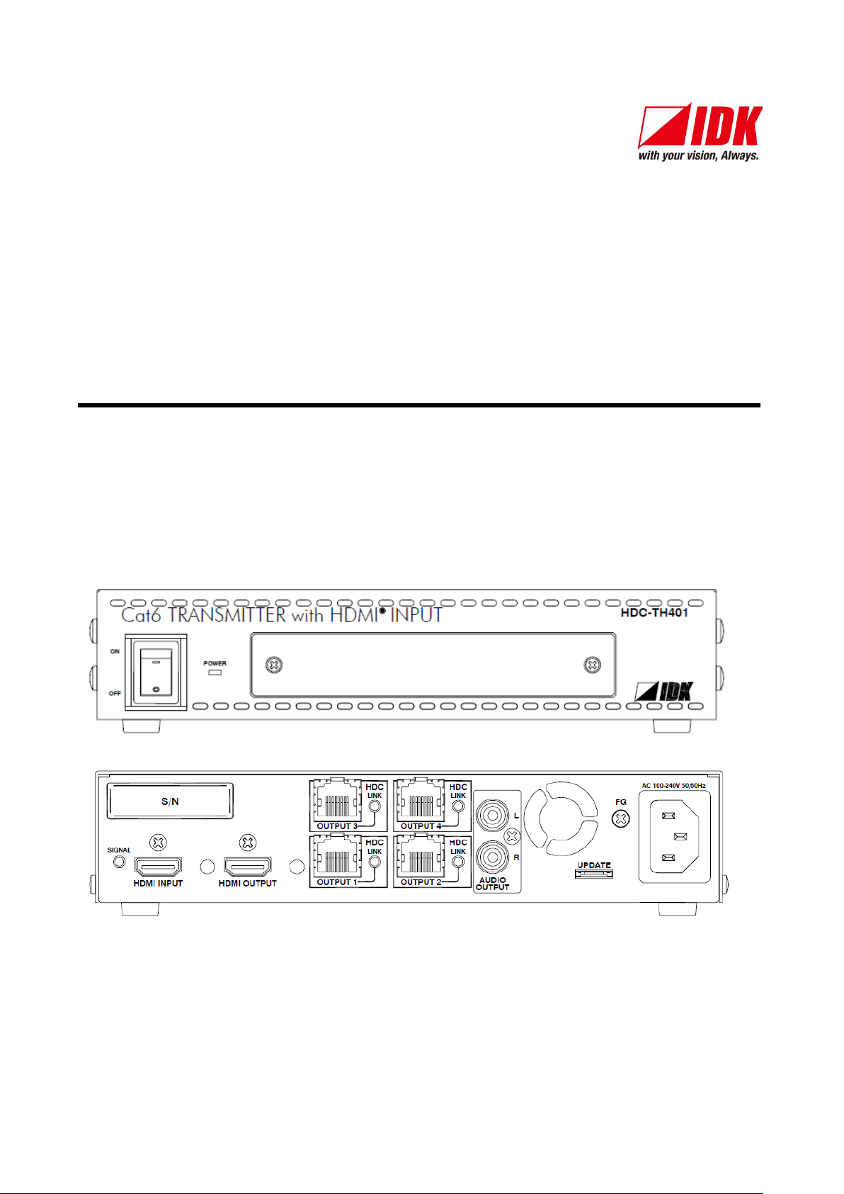
3 Panels ........................................................................................................................................................... 12
3.1 Front panel ............................................................................................................................................. 12
3.2 Rear panel .............................................................................................................................................. 13
4 Application example ...................................................................................................................................... 15
5 Precautions ................................................................................................................................................... 16
5.1 Installation .............................................................................................................................................. 16
5.2 Connection ............................................................................................................................................. 16
5.2.1 Connecting HDMI ............................................................................................................................ 16
5.2.2 Connecting DVI cable ...................................................................................................................... 17
5.2.3 Twisted pair cable for long-haul transmission ................................................................................. 18
6 Basic Operation ............................................................................................................................................ 19
6.1 Notes on use .......................................................................................................................................... 19
6.2 Menu operation ...................................................................................................................................... 20
6.3 Initialization ............................................................................................................................................ 21
7 Menus ........................................................................................................................................................... 22
7.1 Menu operation ...................................................................................................................................... 22
7.2 Menu list ................................................................................................................................................. 23
7.3 Copying EDID ........................................................................................................................................ 25
7.4 Setting EDID resolution .......................................................................................................................... 27
7.5 Setting external EDID............................................................................................................................. 31
7.6 Setting Copy EDID ................................................................................................................................. 32
7.7 Setting No-signal input monitoring time of Video signal ........................................................................ 33
7.8 Setting Deep Color ................................................................................................................................. 35
7.9 Setting PCM Audio ................................................................................................................................. 36
7.10 Setting AC-3/Dolby Digital Audio .......................................................................................................... 37
7.1 1 Setting AAC Audio ................................................................................................................................ 38
7.12 Setting Dolby Digital + Audio ............................................................................................................... 39
7.13 Setting DTS Audio ................................................................................................................................ 40
7.14 Setting DTS-HD Audio ......................................................................................................................... 41
7.15 Setting Dolby TrueHD Audio ................................................................................................................ 42
7.16 Setting Audio channel .......................................................................................................................... 43

HDC-TH401/201/101 User Guide
9
7.17 Setting EDID physical address cop y .................................................................................................... 45
7.18 Setting audio output ............................................................................................................................. 46
7.19 Selecting CEC ...................................................................................................................................... 46
7.20 Selecting EDID WXGA ......................................................................................................................... 47
7.21 Displaying firmware version ................................................................................................................. 48
7.22 Setting maintenance menu display ...................................................................................................... 49
7.23 Setting forced output HDMI mode........................................................................................................ 50
7.24 Setting HDCP input .............................................................................................................................. 51
7.25 Setting how long video output requests of sink device are ignored ..................................................... 52
7.26 Setting output color conversion manually ............................................................................................ 53
7.27 Displaying status .................................................................................................................................. 54
8 Specification ................................................................................................................................................. 60
8.1 Product specification .............................................................................................................................. 60
8.2 HDMI Type A connector ......................................................................................................................... 61
8.3 RJ-45 connector pin assignment ........................................................................................................... 61
9 Trouble shooting ........................................................................................................................................... 62
HDC-TH401/201/101 User Guide
10
Transmitter
HDC-RD100-B
HDC-RH100-C
Receiver
Blu-ray player
Projector
HDC-TH401/201/101
HDC-RH401/201/101
Distribution
Monitor
DVI (HDCP)
HDMI (HDCP)
Monitor
HDMI (HDCP)
Analog audio output
Speaker
HDC-S400/200
Monitor
HDMI (HDCP)
Cat6 cable
Up to 197 ft.
(60 m)
HDC-RH401/201/101
HDMI (HDCP)
Up to 16 ft.
(5 m)
Up to 16 ft.
(5 m)
Cat6 cable
Up to 197 ft.
(60 m)
Up to 16 ft.
(5 m)
Cat6 cable
Up to 197 ft.
(60 m)
Up to 16 ft.
(5 m)
*
Up to 16 ft.
(5 m)
*
*Up to 7 ft. (2 m) for HDC-RH100-C
Rx
RS-232CLAN
Cat6 Rx for HDMI
POWER LINK HDCP
STATUS
POWER LINK HDCP
POWER LINK HDCP
STATUS
FG DC 5V 2A
HDC-RH100-C
INPUT
DON'T
CONNECT
LAN
HDBaseT
CAUTION
!
(MAX 2M)
HDMI
OUTPUT
INPUT
RS-232C
FG DC 5V 3A
CAUTION
DON'T
CONNECT
LAN
Rx
Cat6 Rx for DVI
HDC-RD100-B
POWER
STATUS
LINKHDCP
LAN
SIGNAL
DVI OUTPUT
!
HDBaseT
(HDCP)
Splitter Receiver
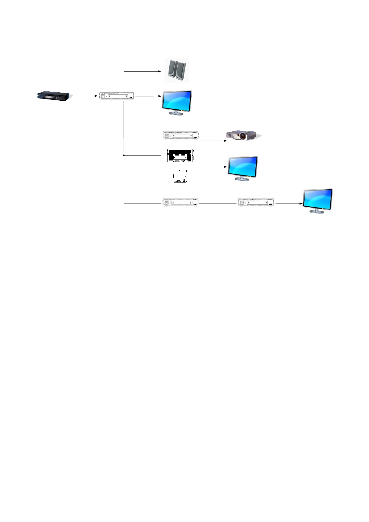
1 Product Outline
[Fig. 1.1] Diagram
The HDC-TH401/201/101 (hereaf ter referred to as “HDC”) are HDbaseT transmitter and splitter with HDMI
local output. HDMI signals are distributed up to 4. Video and audio signals can be extended using IDK’s
HDBaseT extender. The HDC also supports audio de-embedding function.

HDC-TH401/201/101 User Guide
11
2 Features
■ Video
・ Up to 1080p/QWXGA (Reduced Blanking)
・ HDCP 1.4
・ Up to 197 ft. (60 m) over Cat6 cable
・ Local monitor output
・ Anti-snow
*1
■ Audio
・ De-embedding
■ Others
・ EDID emulation
・ Displaying I/O signal status
*2
・ Connection Reset (HDMI output only)
◆ HDCP: High-bandwidth Digital Content Protection System
*1
The anti-snow feature automatically fixes snow noise that is a specific symptom of HDCP-compliant
signals and mainly occurs at start-up. This feature does not work when snow noise has already occurred
during startup or when it occurs due to a bad condition of the transmission line.
*2
For digital systems, some problems, such as an HDCP authentication error, can often be recovered by
physically disconnecting and reconnecting the digital cables. However, the Connection Reset feature will
fix these problems automatically without the need to physically plug and unplug the cables. It creates the
same condition as if the cable were physically disconnected and reconnected. This feature only works for
the HDC’s output. If other devices are connected between the HDC’s output and sink device, this feature
may be invalid.

HDC-TH401/201/101 User Guide
12
① ②
#
Name
Description
POWER switch and LED
Powers on/off the HDC
See “6.2 Menu operation” for details.
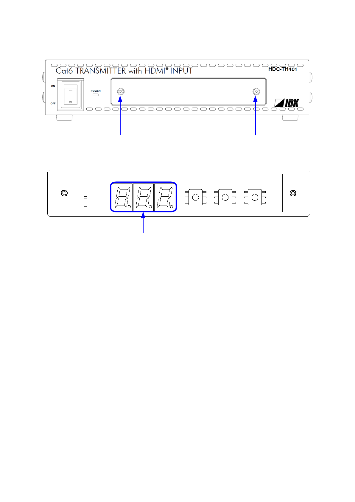
3 Panels
3.1 Front panel
[Table 3.1] Front panel’s name and description (HDC-TH401/201/101)
①
② Segment display and
menu operation buttons
[Fig. 3.1] Front panel drawing
The POWER LED lights when the HDC is powered on.
Sets menu using “SET”, “+”, and “-” buttons.
(The cover plate with access to the menu is removable.)
Tip:
Front panels for HDC-TH401/201/101 are common.

13
3.2 Rear panel
②
①
③
④ ⑥ ⑧⑤ ⑦
②
①
③
④ ⑥ ⑧⑤ ⑦
②
①
③
④ ⑥⑧⑤⑦
HDC-TH401/201/101 User Guide
[Fig. 3.2] Rear panel drawing (HDC-TH401)
[Fig. 3.3] Rear panel drawing (HDC-TH201)
[Fig. 3.4] Rear panel drawing (HDC-TH101)

HDC-TH401/201/101 User Guide
14
(HDMI OUTPUT)
monitors and projectors.
HDC output connector
Output connectors f or ex te nding digital sig nals. T he HDC L INK
HDC-TH101: OUTPUT1 only
(UPDATE)
Frame groung (FG)
Use for bonding chassis to local ground.
AC connector (AC100-240V)
Connector for supplied AC cable.
[Table 3.2] Front panel’s name and description (HDC-TH401/201/101)
# Name Description
① SIGNAL LED (SIGNAL) Illuminates when signal is input to HDMI INPUT.
② HDMI inpur connector
(HDMI INPUT)
③ HDMI output connector
④
(OUTPUT1 to OUTPUT4)
Input connectors f or HDMI signal to interface source devices,
such as Blu-ray players.
Output connectors for HDMI signal to sink devices, such as
LED illuminates when connected to an HDC series receiver.
HDC-TH401: OUTPUT1 to OUTPUT4
HDC-TH201: OUTPUT1 and OUTPUT2
⑤ Analog audio output connector
(AUDIO OUTPUT)
⑥ Maintenance connector
⑦
⑧
Output connector for outputting analog audio signal from HDMI
input connector. See “6.1 Notes on use” for audio signals that
can be output.
Factory use only.

15
4 Application example
Transmitter
HDC-RD100-B
HDC-RH100-C
Receiver
Blu-ray player
Projector
HDC-
TH401/201/101
HDC-RH401/201/101
Distribution
Monitor
DVI(HDCP)
HDMI(HDCP)
Monitor
HDMI(HDCP)
Analog audio output
Speakers
HDC-S400/200
Monitor
HDMI(HDCP)
Cat6 cable
Up to 197 ft.
(60 m)
HDC-
RH401/201/101
HDMI(HDCP)
Up to 16 ft.
(5 m)
Up to 16 ft.
(5 m)
Cat6 cable
Up to 16 ft.
(5 m)
Cat6 cable
Up to 16 ft.
(5 m)
*
Up to 16 ft.
(5 m)
*
* For HDC-RH100-C, up to 7 ft. (2 m)
Rx
RS-232CLAN
Cat6 Rx for HDMI
POWER LINK HDCP
STATUS
POWER LINK HDCPPOWER LINK HDCP
STATUS
FG DC 5V 2A
HDC-RH100-C
INPUT
DON'T
CONNECT
LAN
HDBaseT
CAUTION
!
(MAX 2M)
HDMI
OUTPUT
INPUT
RS-232C
FG DC 5V 3A
CAUTION
DON'T
CONNECT
LAN
Rx
Cat6 Rx for DVI
HDC-RD100-B
POWER
STATUS
LINKHDCP
LAN
SIGNAL
DVI OUTPUT
!
HDBaseT
(HDCP)
HDBaseT splitter
Receiver
Up to 197 ft.
(60 m)
Up to 197 ft.
(60 m)
HDC-TH401/201/101 User Guide
[Fig. 4.1] Application example
HDC-TH401/201/101 User Guide
16
5 Precautions
Before using, read this document.
5.1 Installation
When installing the HDC, observe the following precautions.
・ Before connecting HDC or an external device, dissipate static electricity by touching grounded
metal such as racks before handling signal cables. Failure to observe this precaution may result
in ESD (electrostatic discharge) damage.
・ Do not block vent holes.
・ When the HDC needs to be mounted in an enclosed space, ensure that sufficient ventilation or
cooling is provided. If inadequately vented, the product’s service life, operation and reliability
may be affected.
5.2 Connection
When connecting the HDC to external devices, please observe the following precautions.
・ Read manuals for the external devices.
・ Before you connecting cables to the HDC or an external device, dissipate static electricity
by touching grounded metal such as racks before handling signal cables. Failure to observe
this precaution may result in ESD (electrostatic discharge) damage.
・ Power all units off before connecting cables.
・ Be sure to fully seat all plugs and connections and dress cables to reduce stress on connectors.
5.2.1 Connecting HDMI
・ Please use HDMI 19-pin TypeA (male) cable which is shorter than 16 ft. (5 m).
・ Be sure to plug cables completely and install them without any stress on connectors.
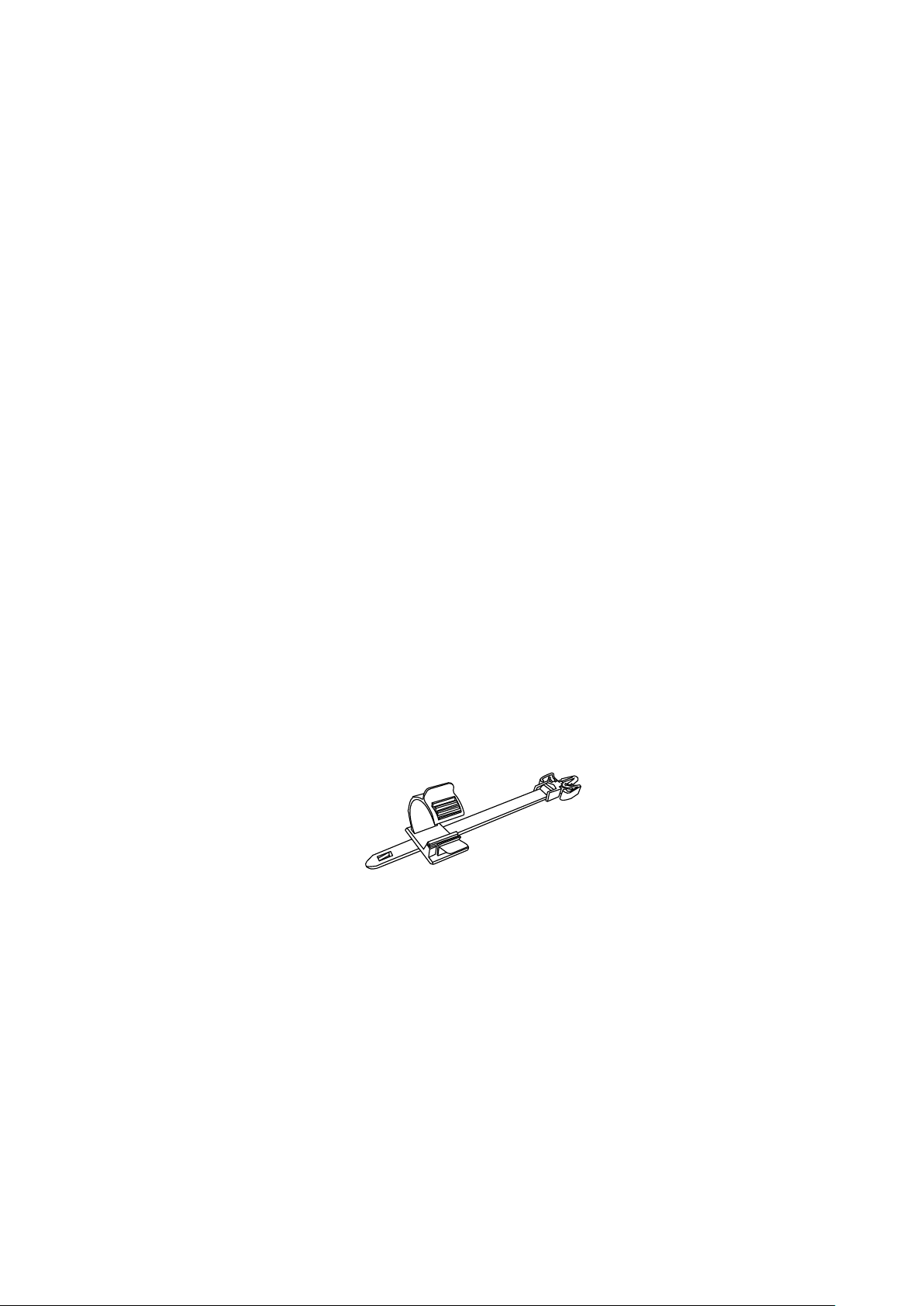
・ Use a cable clamp to prevent those cables from falling off.
[Fig. 5.1] Cable clamp
HDC-TH401/201/101 User Guide
17
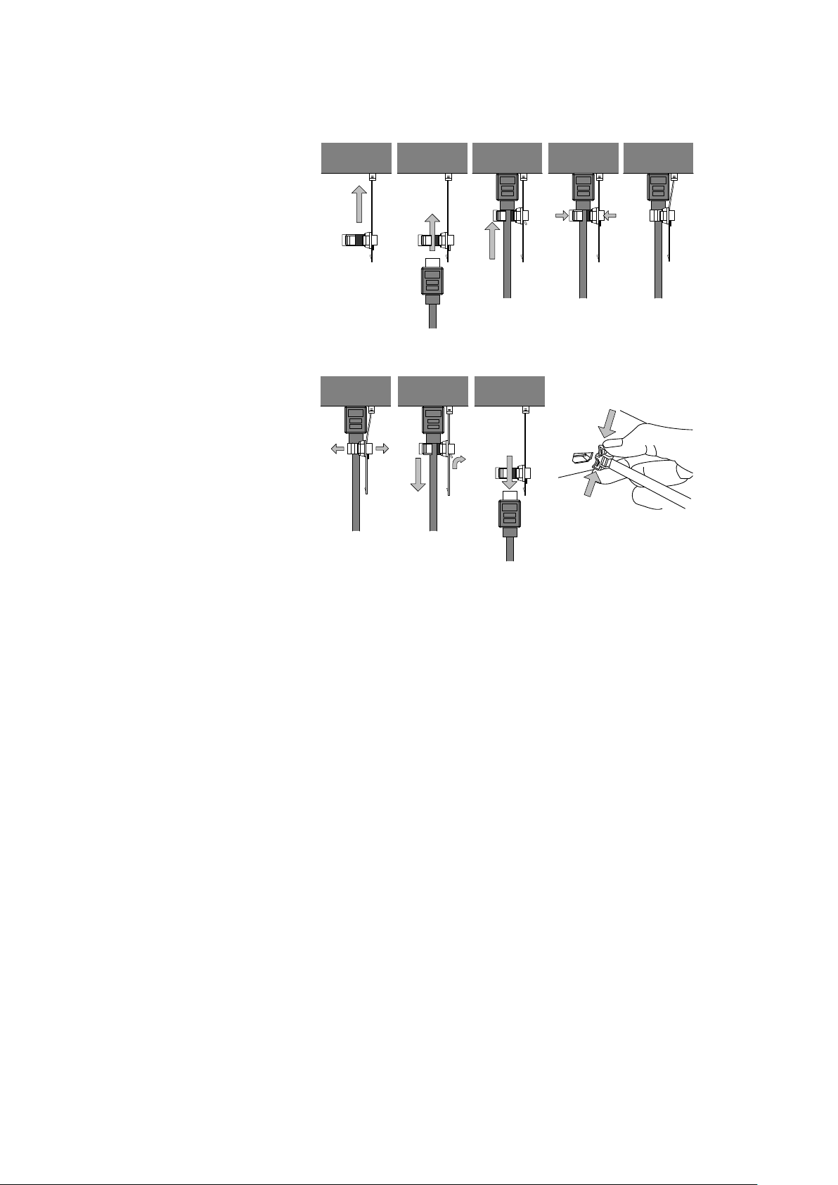
Fixing HDMI cable using cable clamp
Removing HDMI cable and cable clamp
①
②
③
Pull out while pressing
④
② ④ ⑤
① ③
5.2.2 Connecting DVI cable
Use a DVI/HDMI conversion cable for DVI connector of the source.
[Fig. 5.2] Attaching cable clamp

HDC-TH401/201/101 User Guide
18
Noise
influence
Category
Distance
TMDS clock
Remarks
Easily
UTP
Cat5e
98 ft. (30 m)
225 MHz
For 98 ft. (30 m) or longer,
Cat6
197 ft. (60 m)
Less
STP
Cat5e*
197 ft. (60 m)
5.2.3 Twisted pair cable for long-haul transmission
When connecting a twisted pair cable to the HDC, please observe the following precautions.
・ Cat5e/Cat6 UTP/STP can be used, however, we recommend a CAT .5E HDC cable* for the twisted pair
cable which is developed by IDK to maximize quality of video transmission.
・ If using an STP cable, connect the FG connector to an earth ground source. Otherwise, the shielding
feature does not work correctly. When using a UTP cable, we still recommend using the ground connector.
・ The shielded STP cables are less affected by interference or external noise than UTP cables.
・ The connector for twisted pair cable is as same as the connectors which are used for Ethernet (8 core
modular type connector), however, it cannot be connected and use for Ethernet because the way of data
transmission is different.
・ The maximum extension distance of Cat5e/Cat6 UTP/STP cable is the shorter maximum extension
distance of the connected HDC receiver and sink device.
・ For pin assignments, apply T568A or T568B standards for straight through wiring.
・ Do not give connection cables a strong pull. The allowable tension of the twisted pair cable is 110 N.
・ Do not bend the connection cable at a sharp angle. Keep the bend radius four times of the cable diameter
or longer.
・ Do not tie the cable tightly; leave a space allowing the cable to move slightly.
・ If you use the same cables, we recommended keeping a distance between the cables or not to place the
cables closely in parallel.
・ Keep the twisted pair cable as straight as you can. If you coil the cable, it is easily affected by noise.
・ Do not place this product in an electrically noisy environment, since high-speed signal is transmitted.
Particularly when you use a high-output radio around this device, video or audio may be interrupted.
・ If the distance between the transmitter and receiver is 197 ft. (60 m) or shorter, up to two cable couplers
can be used. Couplers supporting Cat6A (10GBase-T) are recommended.
・ Following table shows extension distance by each twisted pair cable. The extension distance depending
on installation environment.
[Table 5.1] Twisted pair cable and extension distance
affected
affected
*
The CAT.5E HDC cable is a double-shielded twisted pair cable that optimizes video signal transmission.
It is certified to 500 MHz bandwidth at distance up to 328 ft. (100 m) and verified to meet requirements
specified by HDBaseT Alliance. The double-shielded structure protects video signal from outside
interference.
Note:
If there is a problem in the transmission path, video or audio may be interrupted. Check the precautions above.
If the problem still cannot be solved, shortening the twisted pair cable may remedy the problem.
Cat6
≦
Cat5e STP, Cat 6 UTP/STP,
CAT.5E HDC
*
cables are
recommended.

HDC-TH401/201/101 User Guide
19
Audio format
Details
Example of medias
Dolby Digital+, DTS-HD,
6 Basic Operation
6.1 Notes on use
1) Extension distance is 197 ft. (60 m) using Cat6 cable. The maximum extension distance of a twisted pair
cables is the shorter distance of the maximum extension distances of transmitter/receiver/sink device
connected to the HDC.
2) Input power is AC 100 V to 240 V. Ensure before you turn on the unit.
3) xvYCC, Lip Sync, HEC, 3D, and ARC are not supported.
4) For DVI signal output, use DVI-I or DVI-D HDMI conversion cable (DualLink DVI is not supported).
5) CEC is pass through between INPUT and OUTPUT which is selected in “7.19 Selecting CEC”. Please
test CEC connection before you use other manufacturers source and sink devices.
6) Audio format which is shown in below table are supported. Factory default setting is 2ch liner PCM.
If you use the HDC’s analog audio output, first select 2ch liner PCM and then set the audio format of the
source device. If you use ot her format, select internal EDID and select expected audio format.
7) 10bit/component (30bit/pixel) and 12bit/component (36bit/pixel) Deep Color are supported. If you cannot
get Deep Color output from source device, please set Deep Color setting of the HDC, and then set the
source device video settings. Factory default is 8bit/component (24bit/pixel).
8) Use IDK’s HDBaseT extender supporting DVI signals to transmit HDCP-compliant DVI signals.
9) If you got any trouble, see “9 Trouble shooting”.
[Table 6.1] Supported digital audio format
2-channel LPCM 2ch, 32 to 192kHz, 16/20/24bit
Multi-channel LPCM 8ch, 32 to 192kHz, 16/20/24bit DVD-Audio
AC-3, Dolby Digital, DTS Bit stream DVD-Video
Dolby TrueHD
AAC Bit stream TV broadcast
◆ CEC : Consumer Electronics Control
◆ Deep Color : The HDC supports 30bit/36bit Deep Color.
CD, DVD-Video,
DVD-Audio
Bit stream HD DVD, Blu-ray Disc
HDC-TH401/201/101 User Guide
20
Loosen two s cr e ws to remove t he c ov er.
READY
ERROR
-+
MENU
SET
STATUS
7-SEGMENT LED
READY LED
: Illuminates : EDID can be loaded and saved.
ERROR LED
: Illuminates : EDID loading fails
SET button
: Sets menu and setting value.
6.2 Menu operation
[Fig. 6.1] Removing cover
[Fig. 6.2] Menu operation buttons
Flashes : DVI signal with HDCP is being output.
7-SEGMENT LED : Displays menu number of setting value.
- and + buttons : Switches menu or changes setting value.
 Loading...