

IDK HDC-RH401, HDC-RH201, HDC-RH101 User Manual

HDC-RH401/201/101 Users Guide
HDC-RH401
ON
OFF
Cat6 RECEIVER with HDMI O UTPUTS
POWER
AC90-250V
HDC INPUT
OUTPUT 1
LINK
HDC OUTPUT
OUTPUT 2
OUTPUT 3 OUTPUT 4
SIGNAL LINK
UPDATE
FG
S/N
HDMI/DVI
HDMI/DVI
HDMI/DVI
HDMI/DVI
HDBaseT Daisy Chain Receiver & HDMI Splitter
HDC-RH401/201/101
<User’s Guide>
Ver.1.5.0
• Thank you for choosing our produc t.
• To ensure the best perf ormance of this product, please read this User’s Guide fully and caref ully before
using it and keep thi s manual beside this product.
IDK Corporation
1

HDC-RH401/201/101 Users Guide
Trademarks
● Blu-ray Disc and Blu-ray are trademarks of Blu-ray Disc Associa tion.
● The terms HDMI and HDMI High-Definition Multimedia Interface, and the HDMI Logo are tradem arks or
registered tradem ar k s of HDM I Licensi ng, LLC in the United States and other c ountries.
● PJLink is a trademar k in Japan, the Unit ed S tates, and other countries/regions.
● HDBaseT™ and the HDBaseT Alli anc e Logo ar e trademarks of the HDBaseT Alliance.
● Microsoft, Wi ndows, Int er net Explorer are either registered trademarks or tradem ar k s of the Mic r osoft
Corporation in the United States and other countri es.
● ETHERNET is registered trademar k of Fuji Xerox Cor poration.
● Mozilla, Firef ox and its logo are trademarks or registered t r adem ar k s of the Mozilla Foundation in the
United States and other c ountries.
● Google Chrome is tradem ar k or registered trademark of Google I nc.
● Javascript
the United Stat es and other c ountries.
● Oracle and Java are register ed trademarks of the Oracle Corporat ion and its related companies in the
United States and other c ountries.
● All other company and produc t names mentioned in this manual are either r egistered trademark s or
trademark s of their r espect ive owners. In this manual, the “®” or “™” marks may not be specified.
®
is trademark or regi ster ed trademark of the Oracle Corporation and its related companies in
2
HDC-RH401/201/101 Users Guide
クラス
1 レーザ
製品
CLASS
1
LASER PRODUCT
Before reading this manual
All rights reserved.
Some of the contents in this User’s Guide such as appearance diagrams, menu operations,
communicati on c ommands, and so on m ay differ depending on the version.
This User’s Guide is subject to change without notice. You can download the latest version from IDK’s
website at: http://www.idk.co.jp/en/index.html
The lasers in this product meet Class 1 Laser Safety per FDA/ CDRH and
EN (IEC) 60825 laser safety standards which specif y design safet y.
FCC STATEMENT
This equipment has been tested and found t o comply with the limits for a Class A digital device, pursuant to
part 15 of the FCC Rules. These limits are designed to provide reasonable protection against harmful
interfer ence when the equipm ent is operated in a c ommerci al environment . This equipm ent generates, uses,
and can radiate radio frequency energy and, if not installed and used in accordance with the instruction
manual, may cause harmful interference to radio communications. Operation of this equipment in a residential
area is likely to cause harmful interf erenc e, in which case the user will be required t o correct the interf erence
at his own expense.
Note: This equipm ent was tested with shiel ded cables on the peripheral devic es. Shielded cables must be
used with the equipm ent t o ensure com pliance with FCC emissions limits.
CE MARKING
This equipment complies with the essential requirements of the relevant European health, safety and
environmental protection legislation.
WEEE MARKING
Waste Electrical and Elect r onic E quipment (WEEE), Directive 2002/ 96/EC
(This directive is only valid in the EU).
This equipment complies with the WEEE Directive ( 2002/96/EC) marking requi r em ent.
The left marking indicates that you must not discard this electrical/electronic equipment in
domestic household waste.
This equipment complies CISPR 22/EN 55022, VCCI, and FCC Part 15 Subpart B standards. To comply
these standards, please use Fer r ite Core to 5 cm from cable connector.
3
HDC-RH401/201/101 Users Guide
Enforcement Symbol
Description
Symbol
Description
Example
Caution
Warning
Safety instructions
Read and understand all safety and operating instruc tions before using this device. Follow all instructions and
cautions as detailed in this document.
Caution
Prohibition
Indicates the pr esence of a hazard that may result in death or serious
personal injury if the warning is ignored or the equipment is handled
incorrectly.
Indicates the presence of a hazard that may cause minor personal
injury or property damage if the caution is ignor ed or the equipment is
handled incorr ec tly.
This symbol is indicated to alert the user. (Warning and caution)
This symbol is intended to pr ohibit the user from actions.
Electrical
Hazard
Do not
disassemble
This symbol is intended to instr uc t the user.
Instruction
Unplug
4
Do not place the product in any unstabl e place.
Install th e product t o a hor iz on t al and stabl e pl ac e. Otherwise, it may fall/turn over and lead to injury.
Do not place the product in any environment with vibration.
Otherw ise, it may mo ve/fall and l ead to injury.
Keep out any foreign objects.
from the vent holes.
For power cable/ plug :
damaged, contact IDK.
disassemble
Do not repair, modify or disassemble.
In the event of lighting or thunder, do not touch the main unit or cables such as
For insta lla t i on:
or IDK. Otherwise, it may cause fire, electric shock, injury, or property damage.
Set the power plug in a convenient place to unplug easily.
when you do not use it for a long period.
Plug the po we r plug into appropriate outlet completely.
plug or loos en ed outlet.
Clean the power plug regul arly.
If the plug is covered in dust, it may cause fire due to reduced insulating power.
Unplug immediately if the product smokes, makes unusual noi se, o r smell s.
the product stops smoking, contact IDK.
Unplug immediately if you drop the product or if the cabinet is damaged.
and repair, contact IDK.
Unplug immediately if water or other objects are directed inside.
contact IDK.
For connection
Warning
Prohibition
HDC-RH401/201/101 Users Guide
In order to avoid fire or electric shock, do not allow foreign objects, such as metal and paper, to enter the product
・ Do not scratch, heat, or modify, including extending them.
・ Do not pull, put heavy stuff on them, or pinch them.
・ Do not bend, twist, or tie them together forcefully.
If they are used in those states continuously, it may cause fire or electric shock. If power cables/plugs become
Do not
Do not touch
Instruction
Unplug
Since the product includes high-voltag e p arts, thos e acti ons m ay c au s e fir e or electric sh oc k. For internal
inspections or repairs, contact IDK.
power cable and LAN cable.
Contact m ay cause electric shock
The product is intended to be installed by skilled technicians. For installation, please contact a system integrator
You can eas il y un plug in cas e of an y ext r aordinar y failure or ab normal si tu ation, and it also helps f or un pl ug gi ng
If the plug is plugged incompletely, it may overheat which causes electrical shock or fire. Do not use damaged
If you continue to use the product under those situations, it may cause electric shock or fire. After confirming that
If you continue to use the product under those situations, it may cause electrical shock or fire. For maintenance
If you contin u e t o us e it under those situati ons , i t m ay c ause electrical shock or fire. For maintenance and repair ,
Diff erences in ground poten ti al am on g t h e product and periph eral devic es m ay c ause electric shock or dam ag e
of the devices. When using cables to connect devices, including connection of long-distance transmission,
unplug th e power cabl es of all r el ated devic es .
Instruction
After conne c ting signal/control cables of each de vice, plug in t h e power cabl es of eac h d evice.
5

For insta lla t i on
Never insert onl y the screws i nto t he holes aft er rem oving the r ubber feet. It m ay lead to
Do not place the product in any place where it will be subjected to high
Do not block the vent holes.
Do not exceed ratings of outlet and wiring devices.
Use only the provided AC adapter and power cable.
different AC power cables,
Use and store the product within the specified temperature/humidity range.
Unplug the power plug before cleaning.
Caution
Prohibition
HDC-RH401/201/101 Users Guide
temperatures.
If the product is subjected to direct sunlight or high temperatures, it may cause fire.
Do not place the product in humid, oil smoke, or dusty place.
If the product is placed near humidifiers or dusty area, it may cause fire or electric shock.
If ventilation slots are blocked, it may cause fire or failure due to internal heat.
Do not put heavy items on the product.
It may fall/turn over and lead to injury.
If several pl ugs are put in an out let, it may c ause fire and electric shock.
If non-c ompliant ad apter or power c ables is used, it may c ause fire or electr ical shock. Use the provid ed AC
power con nect ion c able. If you want to us e your prod uct in oth er c ountri es that us e
contact IDK.
No wet hands
Instruction
Do not plug or unplug with wet hands.
It may cause electrical shock.
If the prod uc t is used outsi d e th e range continuously, it may cause fire or electric shock.
Turn off devices when th ey are connect ed to another device.
It may cause fire or electric shock.
Unplug the power plug if you do not use the product for a long period.
In case of defect, it may cause fire.
Unplug
It may cause electric shock.
For rack mount devices:
Mount the product to the rack meeting EIA standards, and maintain spaces above and
below for ai r cooling. For your saf ety, attach an L-shape bracket i n additi on to the mount
bracket kit for the f r ont panel in order to balance the weight.
Instruction
For devices with rubber feet:
damage when the screws contact electrical circ uit or parts i nsi de of the product.
To put the rubber feet back on, use only provi ded r ubber feet and screws.
Instruction
6

Do not place the product at elev ations of 2,000 meters (6562 feet) or higher abov e sea
Altitude:
level. Failur e to do so may shorten the life of the internal parts and result in malfunctions.
Instruction
HDC-RH401/201/101 Users Guide
7

HDC-RH401/201/101 Users Guide
Table of Contents
1 Included items......................................................................................................................................10
2 Product outline ..................................................................................................................................... 11
3 Features ..............................................................................................................................................12
4 Panels .................................................................................................................................................13
4.1 Front panel ...................................................................................................................................13
4.2 Rear panel ....................................................................................................................................14
5 Example connection .............................................................................................................................16
6 Precautions ..........................................................................................................................................17
6.1 Installation ....................................................................................................................................17
6.2 Cabling .........................................................................................................................................18
6.2.1 Cables ..........................................................................................................................................19
6.2.2 Twisted pair cable .........................................................................................................................19
7 Basic operati on ....................................................................................................................................21
7.1 Menu operation key s .....................................................................................................................21
7.2 Initialization ...................................................................................................................................22
7.3 Notes on use.................................................................................................................................23
8 Menus..................................................................................................................................................24
8.1 Menu operation .............................................................................................................................24
8.2 Menu list .......................................................................................................................................25
8.3 [ F01 to F03 ] Copying EDID .........................................................................................................27
8.4 [ F10 ] Setting EDID resoluti on ......................................................................................................29
8.5 [ F12 ] Setting exter nal E DID .........................................................................................................31
8.6 [ F14 ] setting Copy EDID ..............................................................................................................32
8.7 [ F16 ] Setting No-si gnal input monitoring time of Video signal .......................................................33
8.8 [ F20 ] Setting Deep Color .............................................................................................................35
8.9 [ F22 ] Setting PCM Audio .............................................................................................................36
8.10 [ F24 ] Setting AC-3 / Dolby Digital Audio .......................................................................................37
8.11 [ F26 ] Setting AAC Audio ..............................................................................................................38
8.12 [ F28 ] Setting Dolby Digital + Audio ..............................................................................................39
8.13 [ F30 ] Setting DTS Audio ..............................................................................................................40
8.14 [ F32 ] Setting DTS-HD Audio ........................................................................................................41
8.15 [ F34 ] Setting Dolby TrueHD Audio ...............................................................................................42
8

HDC-RH401/201/101 Users Guide
8.16
[ F36 ] Setting Audio channel.........................................................................................................43
8.17 [ F38 ] Setting CEC physical addr ess copy of E DID .......................................................................45
8.18 [ F65 to F69 ] Setting audio output ON/OFF ..................................................................................46
8.19 [ F75 ] Selecting CEC....................................................................................................................46
8.20 [ F76] Selecting EDID f or WXGA ...................................................................................................47
8.21 [ F90 ] Displaying firmware version ................................................................................................48
8.22 [ F99 ] Setting maintenance/status display menu ...........................................................................49
8.23 [ C01 to C05] Setting forc ed output HDMI mode ............................................................................50
8.24 [ C06 ] Setting HDCP input ............................................................................................................51
8.25 [ C10 ] Setting how long video out put requests of sink device are ignored .....................................52
8.26 [ C55 to C59 ] Setting output color conversion manually ................................................................53
8.27 [ L01 to L69] Displaying status ......................................................................................................54
9 Specification ........................................................................................................................................60
9.1 Product specification .....................................................................................................................60
9.2 HDMI Type A connector.................................................................................................................62
9.3 RJ-45 connector pi n assignment ...................................................................................................62
10 Troubl e shooting ..................................................................................................................................63
9
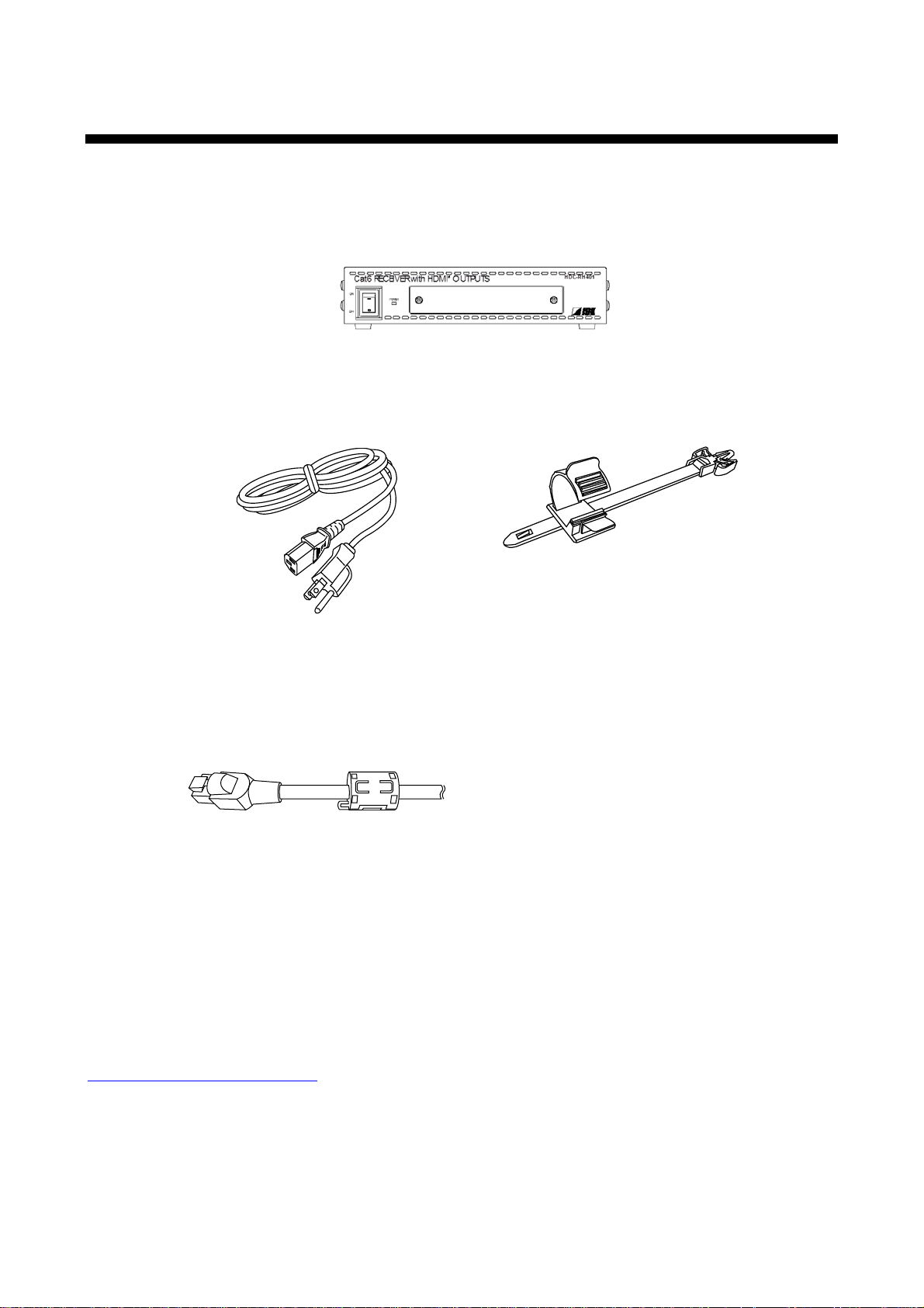
1 Includ e d items
Four (4) for HDC-RH401
Make sure all items below are i ncl uded in the package.
If any items are missing or dam aged, please contact IDK.
One (1) HDBaseT Daisy Chain Receiv er & HDMI Splitter (main unit)
HDC-RH401/201/101 Users Guide
One (1) power cord
(1.8 meters; approximately 5.91 feet)
Cord clamps
One (1) for HDC-RH101
Two (2) for HDC-RH201
Two (2) Ferrite Core
[Fig. 1.1] Included items
You can download the latest version of t he User’s Guide from IDK’s website at:
http://www.idk.co.jp/en/index.html
10
HDC-RH401/201/101 Users Guide
Blu-ray Disc player
HDC-TD100-B
HDC-TH100-C
Cat6 cable
Up to 197 ft. / 60
m
Transmitter
HDC-RD100-B
Projector
Receiver
Monitor
HDC-TH401
ON
OFF
Cat6 TRANSMITTER wit h HDM I INPUT
POWER
HDC-TH401/201/101
HDC-RH401
ON
OFF
Cat 6 RECEI VER wit h HD MI OU TPUTS
POWER
HDC-RH401/201/101
HDMI (HDCP)
Monitor
HDC-S400
ON
OFF
Cat6 SPLITTER
POWER
HDC-S400/200
Cat6 cable
Distribution Amplifier
Distribution
Cat6 cable
Up to 197 ft. / 60 m
Up to 197 ft
. / 60
m
Laptop PC
or
Monitor
HDC-RH100-C
Receiver
HDMI (HDCP)
DVI (HDCP)
HDMI (HDCP)
HDMI (HDCP)
Up to 17 ft. / 5 m
DVI (HDCP)
Up to 17 ft. / 5
m
Up to
17 ft
. /
5 m
Up to 17
ft. / 5
m
Up to 17 ft. / 5 m
Up to 17 ft. / 5 m
*
*
*
*
* Up to 7 ft. / 2m
:
HDC-TH100-C or HDC-RH100-C
RS-232CLAN
Tx
Cat6 Tx for HDMI
POWER LINK HDCP
STATUS
POWER LINK HDCPPOWER LINK HDCP
STATUS
INPUT
(MAX 2M)
OUTPUTFG DC 5V 2A
DON'T
CONNECT
LAN
HDC-TH100-C
HDBaseT
CAUTION
!
HDMI
OUTPUT
RS-232C
FG DC 5V 3A
CAUTION
!
DON'T
CONNECT
LAN
L
AUDIO OUTPUT
R
POWER
STATUS
LINKHDC P
LAN
SIGNAL
DVI INPUT
Tx
Cat6 Tx for DVI
HDC-TD100-B
HDBaseT
(HDCP)
Rx
RS-232CLAN
Cat6 Rx for HDMI
POWER LINK HDCP
STATUS
POWER LINK HDCPPOWER LINK HDCP
STATUS
FG DC 5V 2A
HDC-RH100-C
INPUT
DON'T
CONNECT
LAN
HDBaseT
CAUTION
!
(MAX 2M)
HDMI
OUTPUT
INPUT
RS-232C
FG DC 5V 3A
CAUTION
DON'T
CONNECT
LAN
Rx
Cat6 Rx for DVI
HDC-RD100-B
POWER
STATUS
LINKHDC P
LAN
SIGNAL
DVI OUTPUT
!
HDBaseT
(HDCP)
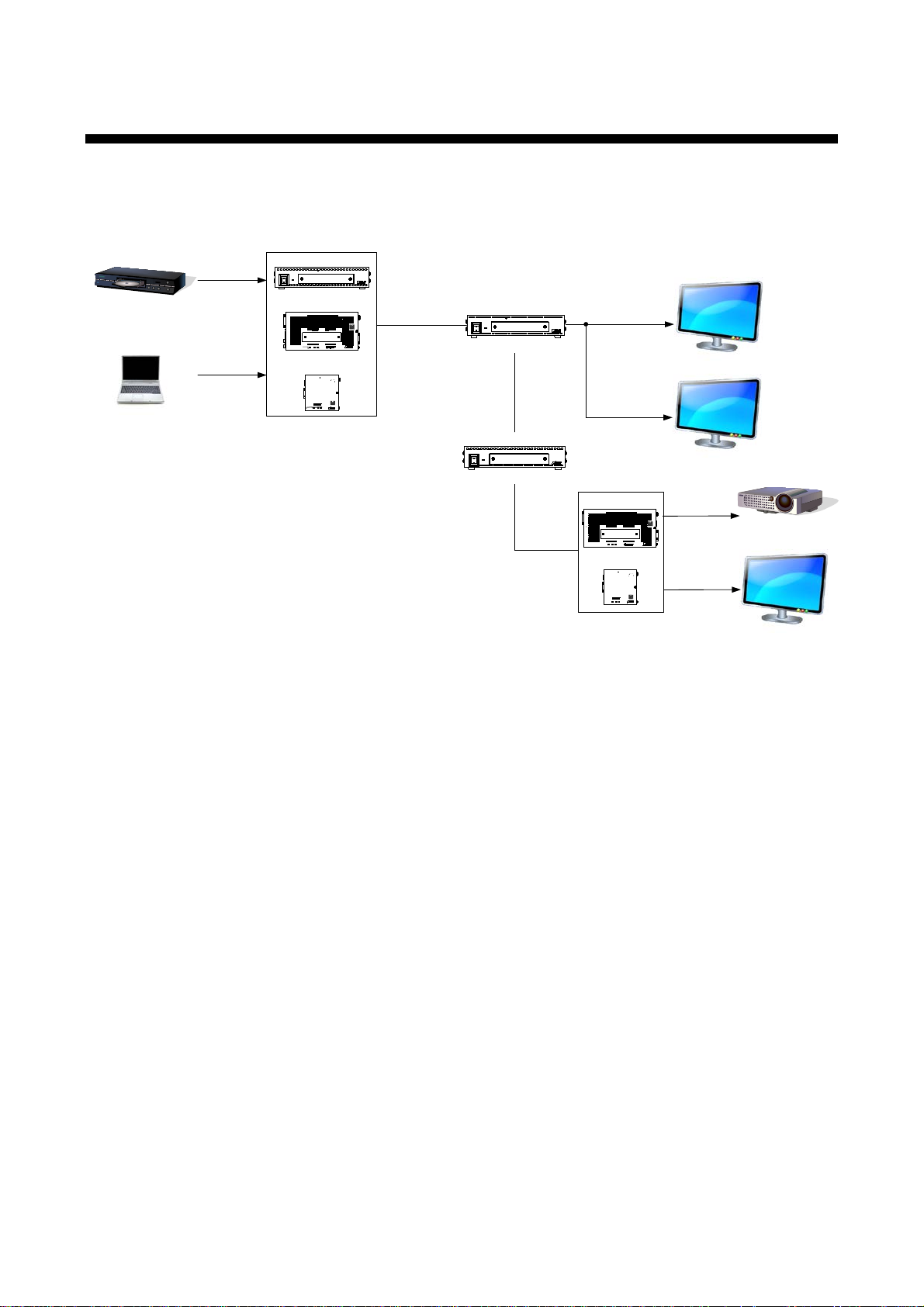
2 Product outline
The IDK HDC-RH101, 201, and 401 are receivers for HDBaseT signal. HDC-RH101, 201, and 401 have
HDBaseT dai sy chain and HDMI signal splitter functions. By using with the IDK HDC series transmitters,
video and audio signals can be extended and distributed to up to four HDMI devices at receiver si de.
[Fig. 2.1] HDC-RH401/201/101 diagram
11

3 Features
■ Video
Up to QWXGA (RB)*1 or 1080p
HDCP supported
Up to 197 ft. approx. / 60 m signal extensi on over a Cat6 cable
Daisy chain connection
Anti-snow
■ Others
EDID emulation
Seven segm ent LED signal status check
Connection Reset (only HDMI output)
*1. (RB) = Reduced Blanking
HDC-RH401/201/101 Users Guide
12
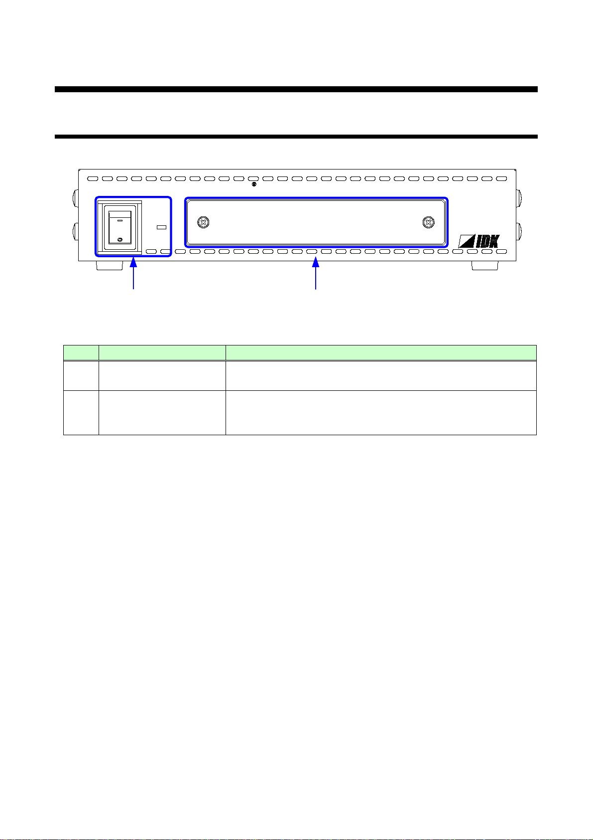
4 Panels
HDC-RH401
ON
OFF
Cat6 RECEIVER with HDMI O UTPUTS
POWER
①
②
(POWER)
The POWER LED lights when the HDC is turned on.
Segment display and
Sets menu using “SET”, “+ ”, and “-“ keys.
【See “7.1 Menu operation”】
4.1 Front pa ne l
[Fig. 4.1] Front panel drawing ( H D C -RH401/201/101)
# Part name Description
①
Power supply switch
Turns on/off the HDC
HDC-RH401/201/101 Users Guide
②
menu operation key s
(The cover plate with access to the menu is removable.)
Note: Front panels for HDC-RH401/201/101 are common.
13
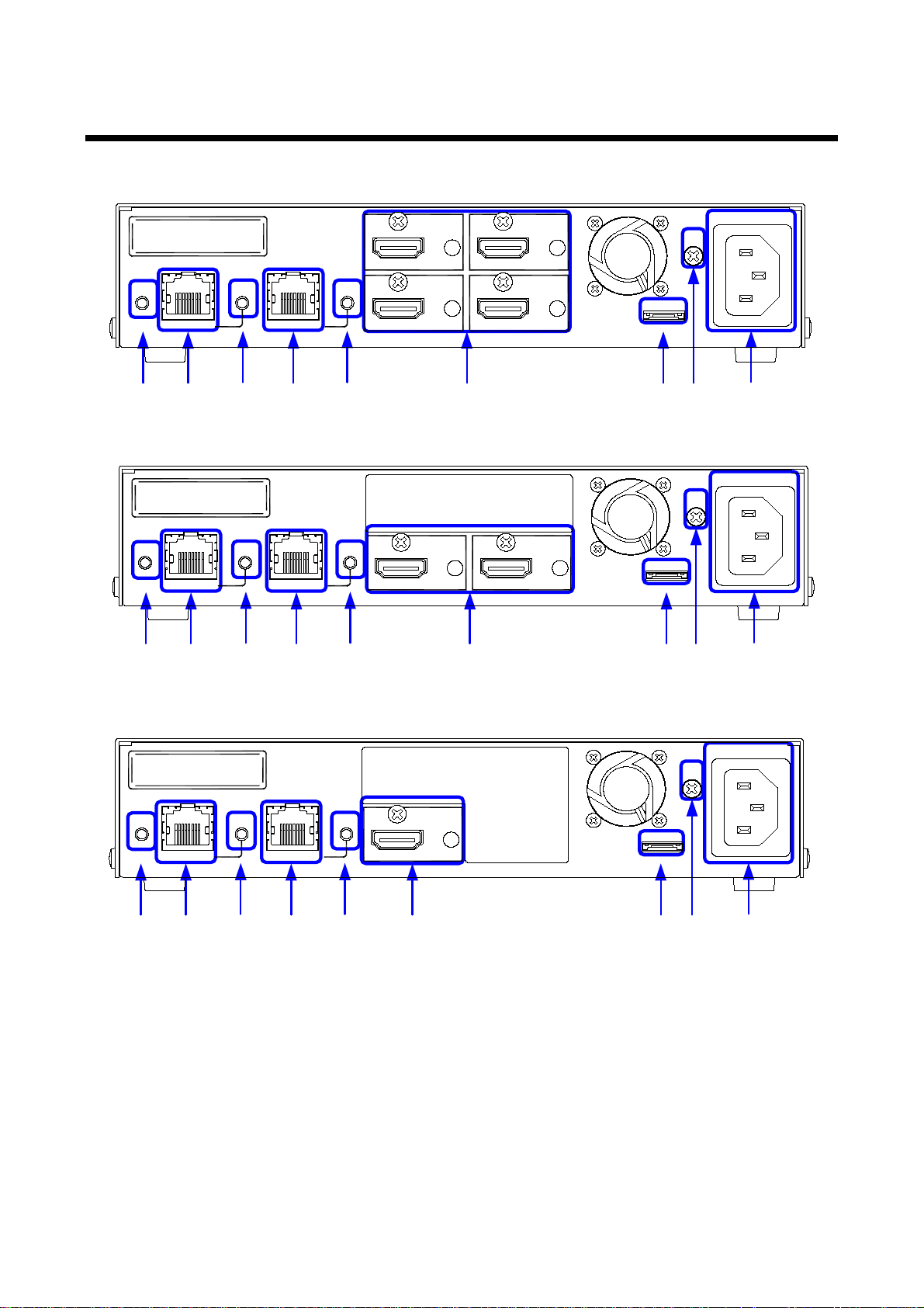
4.2 Rear panel
②
①
③
⑤
④
⑥
⑦
⑨
⑧
AC90-250V
HDC INPUT
OUTPUT 1
LINK
HDC OUTPUT
OUTPUT 2
OUTPUT 3
OUTPUT 4
SIGN AL
LINK
UPDATE
FG
S/N
HDMI/DVI
HDMI/DVI
HDMI/DVI
HDMI/DVI
②①
③
⑤
④
⑥ ⑦
⑨
⑧
AC90-250V
HDC INPUT
OUTPUT 1
LINK
HDC OUTPUT
OUTPUT 2
SIGN AL
LINK
UPDATE
FG
S/N
HDMI/DVI
HDMI/DVI
②①
③ ⑤
④ ⑥
⑦⑨⑧
AC90-250V
HDC INPUT
OUTPUT 1
LINK
HDC OUTPUT
SIGN AL LINK
UPDATE
FG
S/N
HDMI/DVI
HDC-RH401
HDC-RH201
HDC-RH401/201/101 Users Guide
HDC-RH401
[Fig 4.2] Panel drawing
14

HDC-RH401/201/101 Users Guide
Twisted pair input connector
Digital (video/ audio) signals can be extended up to 60 m/197 ft.
LINK LED ( LINK )
The LED lights when HDC transmitter is connected.
(HDC OUTPUT)
using the HDC receiv er.
LINK LED ( LINK )
The LED lights when HDC receiver is connected.
HDMI output
Output connector for HDMI signal.
Frame ground (FG)
An M3 screw is used.
# Part name Description
① SIGNAL LED ( SIGNAL ) The LED lights when video signal input the HDC.
②
(HDC INPUT)
③
④ Twisted pair output connector
⑤
⑥
connector(OUTPUT1 to 4)
⑦ Connector for Maintenance
( UPDATE )
⑧
⑨ AC connec tor ( AC90-250V ) Connector for supplied AC cable.
using the HDC transmitt er.
Digital (video/ audio) signals can be extended up to 60 m/197 ft.
Connector for sink dev ic es such as LCD monit or s and projectors
HDC-RH401 : four (4) output s OUTPUT1 to 4
HDC-RH201 : two (2) outputs OUTPUT1 and 2
HDC-RH101 : one (1) output OUTPUT1
Not used. Please do not connect anything; this connector is for
maintenance only.
Ground for indoor ground terminal.
15
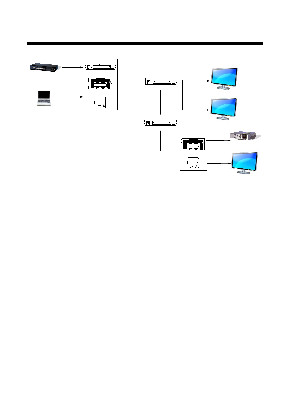
5 Example connection
Blu-ray Disc player
HDC-TD100-B
HDC-
TH
100-
C
Cat6
cable
Up to 197 ft. / 60 m
Transmitter
HDC
-
RD100
-
B
Projector
Receiver
Monitor
HDC-TH401
ON
OFF
Cat6 TRANSMITTER wit h HDM I INPUT
POWER
HDC-TH401/201/101
HDC-RH401
ON
OFF
Cat 6 RECEI VER wit h HD MI O U T PUTS
POWER
HDC-
RH401
/201
/101
HDMI
(HDCP)
Monitor
HDC-S400
ON
OFF
Cat6 SPLITTER
POWER
HDC
-
S400
/200
Cat6 cable
Distribution Amplifier
Distribution
Cat6 cable
Up to
197 ft
. / 60 m
Up to 197 ft. / 60 m
Laptop PC
or
Monitor
HDC-RH100-C
Receiver
HDMI (HDCP)
DVI (HDCP)
HDMI
(HDCP)
HDMI
(HDCP
)
Up to 17 ft. / 5 m
DVI (HDCP)
Up to 17 ft. / 5 m
Up to 17 ft. / 5 m
Up to 17 ft. /
5 m
Up to
17
ft. /
5 m
Up to
17 ft
. /
5 m
*
*
*
*
* Up to 7 ft. / 2
m
: HDC
-TH
100
-C or HDC
-RH100-C
RS-232CLAN
Tx
Cat6 Tx for HDMI
POWER LINK HDCP
STATUS
POWER LINK HDCP
POWER LINK HDCP
STATUS
INPUT
(MAX 2M)
OUTPUTFG DC 5V 2A
DON'T
CONNECT
LAN
HDC-TH100-C
HDBaseT
CAUTION
!
HDMI
OUTPUT
RS-232C
FG DC 5V 3A
CAUTION
!
DON'T
CONNECT
LAN
L
AUDIO OUTPUT
R
POWER
STATUS
LINKHDCP
LAN
SIGNAL
DVI INPUT
Tx
Cat6 Tx for DVI
HDC-TD100-B
HDBaseT
(HDCP)
Rx
RS-232C
LAN
Cat6 Rx for HDMI
POWER
LINK
HDCP
STATUS
POWER LINK
HDCP
POWER
LINKHDCP
STATUS
FG DC 5V 2A
HDC-RH100-C
INPUT
DON'T
CONNECT
LAN
HDBaseT
CAUTION
!
(MAX 2M)
HDMI
OUTPUT
INPUT
RS-232C
FG
DC 5V 3A
CAUTION
DON'T
CONNECT
LAN
Rx
Cat6 Rx for DVI
HDC-RD100-B
POWER
STATUS
LINKHDCP
LAN
SIGNAL
DVI OUTPUT
!
HDBaseT
(HDCP)
HDC-RH401/201/101 Users Guide
[Fig. 5.1] Sample system diagram
16

HDC-RH401/201/101 Users Guide
6 Precautions
Before connecting to external devic es, follow the prec autions below.
6.1 Installation
When installing the HDC, please observe the following precautions.
・ Do not place the HDC on top of anot her HDC.
・ Do not block vent holes. Please secure the space above ambient 30 mm/1.18 inches.
・ Do not install the HDC to an enclosed space. W hen the HDC needs to be installed to EIA rack mount or
an enclosed space, please prepare ventilating equipm ent to keep the ambient temperat ur e at 40 degrees
C/104 degrees F or less. If inadequately vented, the life of parts may be shortened and operations may be
affected.
17
HDC-RH401/201/101 Users Guide
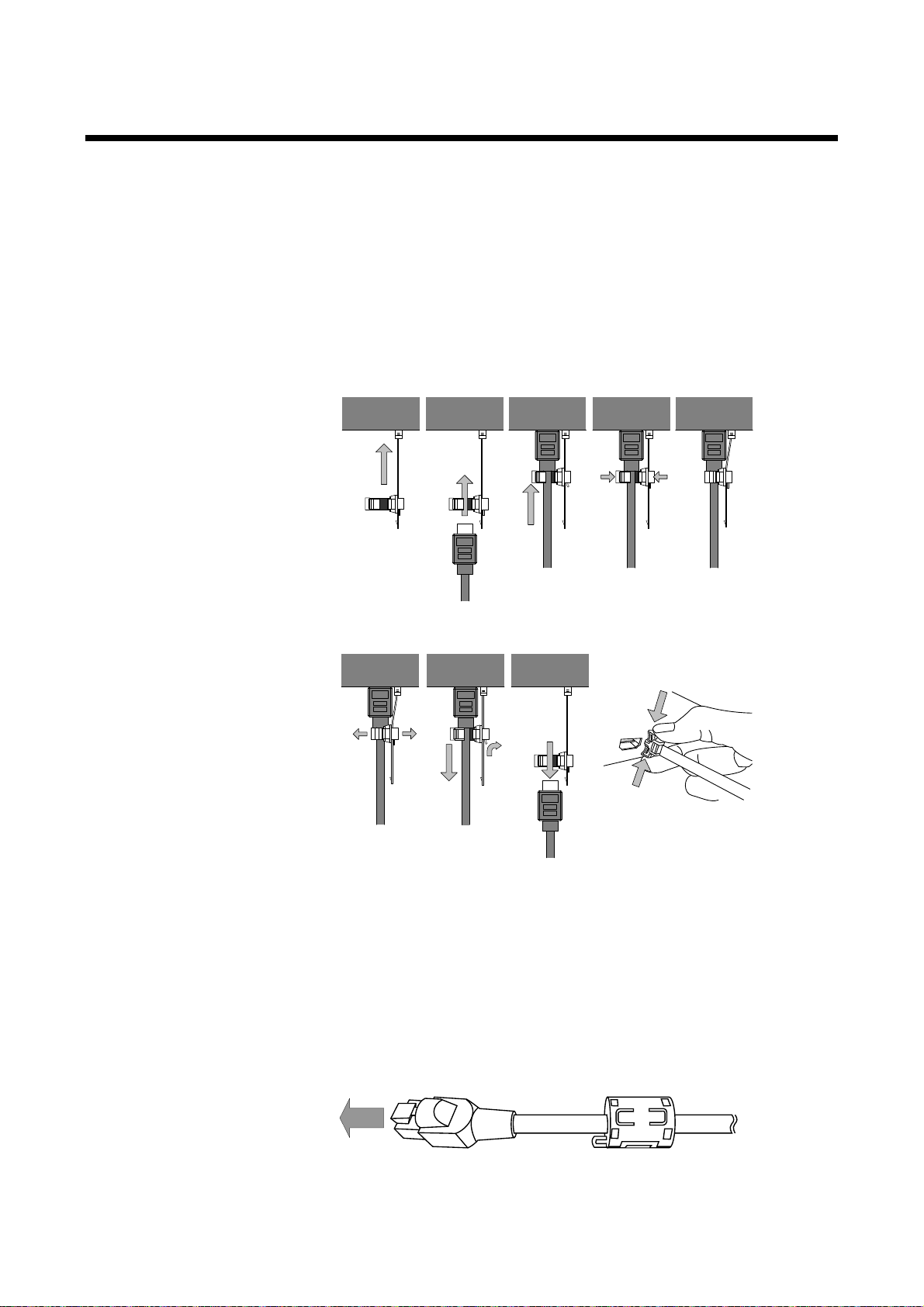
Fixing HDMI cable using cable clamp
Removing HDMI cable and cable clamp
①
②
③
Pull out while pressing
④
② ④ ⑤
①
③
HDC-RH401/201/101
6.2 Cabling
When connecti ng the HDC to t he exter nal dev ices, please observe the following pr ec aut ions.
・ Read manuals of the external devices.
・ Before you connect the cable to the HDC or an external device, please remove electrification of t he body
by touching the metal around that is grounded.
・ Turn off all devises’ power before connecti ng the cable.
・ Be sure to plug cables completely and install them without any stress on connectors.
・ Fix HDMI cables using cable clamps to prevent those cables from falling off.
■ Connecting twist ed pair cables
This equipment complies CISPR 22/EN 55022, VCCI, and FCC Part 15 Subpart B standar ds.
To com ply these standards, please use Ferrite Core to 5 cm from cable connector.
18
[Fig. 6.1] Attaching a cable clamp

HDC-RH401/201/101 Users Guide
External noise
Category
Distance
Dot clock
Memo
Cat5e
30 m/98.42 ft.
exceeds 50 m/164.04 ft.
Cat6
60 m/196.85 ft.
Cat6
6.2.1 Cables
IDK Corporation prov ides various digital cabl es such as HDMI , DVI, and twisted pai r c ables.
Please choose appropri ate cables for your system configur ation. For analog audio and RS-232C, please use
on processing the cable to fit the connectors.
6.2.2 Twisted pair cable
When connecti ng twisted pair cables to the HDC, please observe the following precautions.
・ Cat5e/Cat6 UTP/STP can be used, however, we recomm end a CAT.5E HDC cable* for the twisted pair
cable which i s developed by IDK to maximize quality of video tr ansmission.
・ If using an STP cable, connect the FG connector to an earth ground source. O therwise, the shielding
feature does not work correctly. When using a UTP cable, we still rec ommend using the ground
connector.
・ The shielded STP cables are less affected by interference or external noise than UTP c ables.
・ The connector for twisted pair cabl e is as same as the connectors whi c h ar e used for Ethernet (8 core
modular type connect or ), howev er, it cannot be connected and use for Ethernet because the way of data
transmission is different.
・ The maximum extension distance of Cat5e/Cat6 UTP/STP cable is the shorter m aximum extension
distance of the connect ed HDC r ec eiver and sink device.
・ For pin assignments, apply T568A or T568B standards for straight through wiring.
・ Do not give connection cables a strong pull. The allowable tension of the twisted pair c able is 110 N.
・ Do not bend the connection cable at a sharp angle. Keep the bend radius four times of the cable
diameter or longer .
・ Do not tie the cable tightly; leave a space allowing the cable to move slightly.
・ If you use the s ame cables, we recommended k eeping a distance between the cables or not to place the
cables closely in par allel.
・ Keep the twisted pair cable as straight as you can. If y ou coil the cable, it is easily affected by noise.
・ Do not place this product in an electricall y noi sy environment, since high-speed signal is transmitted.
Particularl y when you use a high-out put radio around this device, video or audio may be interrupted.
・ If the distance between the transmitter and r ec eiv er is 100 m/328.08 feet or less, cables can be joined
using an RJ-45 plug coupl er or wall outl et. Up to two cable couplers are all owed. Couplers supporting
Cat6A (10GBase-T) are recomm ended.
・ Following table shows extension distance by eac h twisted pair cable. The extension distance depending
on installation env ironment.
Affected UTP
Less affected STP Cat5e*
60 m/196.85 ft.
<= 225 MHz IDK recommends Cat5e STP,
Cat6 UTP/STP, or CAT.5E HDC
cable* if the extensi on distance
19

HDC-RH401/201/101 Users Guide
* CAT.5E HDC cable developed by IDK Corporation is double shielded twisted pair cable for high quality video
transmission. It protects video signal from external noise or other int erferences by having doubl e shielded
structure. Its transmission characteristic meets 500 MHz up to 100 m/328.08 ft., and it is certified and
recommended by HDBaseT alli anc e.
【NOTE】
If there is a problem in the transmission pat h, video or audio may be interr upted. Pl ease check the
items above. If the problem still cannot be solved, shorten t he length of the twisted pair cabl e.
20
 Loading...