

IDK FDX-64 User Manual
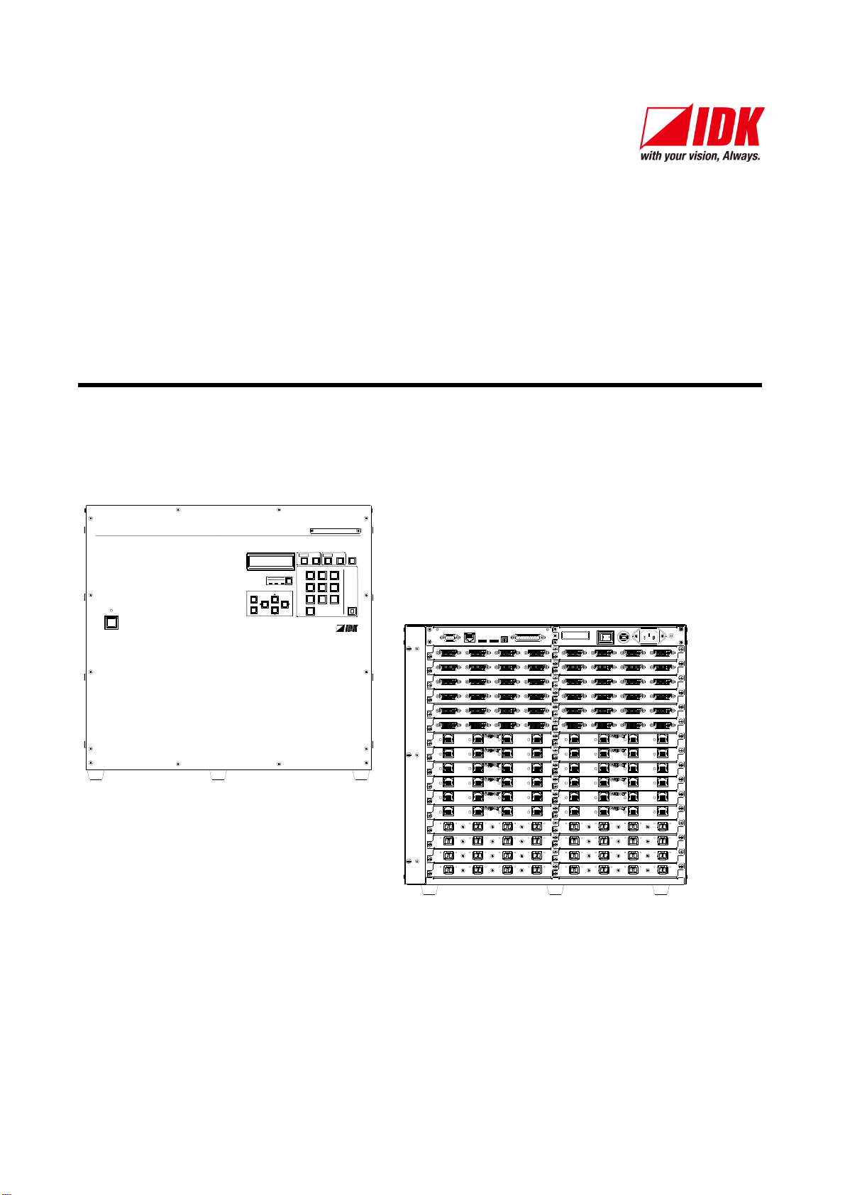
DIGITAL MATRIX SWITCHER
FDX-64
POWER
SET
OUTPUT
ALL
INPUT
OFF
987
654
0
321
LOAD
PRESET
MENU
/SET
ESC
V&A VIDEO AUDIO
SWITCHING MODE
~1 4
~5 8
~9 12
~13 16
~17 20
~21 24
~25 28
OUTPUT
OUTPUT
OUTPUT
OUTPUT
OUTPUT
OUTPUT
OUTPUT
OUTPUT
~29 32
A D
A D
A D
A D
A D
A D
A D
A D
INPUT
~1 4
INPUT
~5 8
INPUT
~9 12
INPUT
~13 16
INPUT
~17 20
INPUT
~21 24
INPUT
~25 28
INPUT
~29 32
A D
A D
A D
A D
A D
A D
A D
A D
INPUT
INPUT
INPUT
INPUT
INPUT
INPUT
INPUT
INPUT
~33 36
~37 40
~41 44
~45 48
A D
A D
A D
A D
~49 52
~53 56
~57 60
~61 64
A D
A D
A D
A D
~33 36
~37 40
~41 44
OUTPUT
OUTPUT
OUTPUT
OUTPUT
~45 48
A D
A D
A D
A D
~49 52
~53 56
~57 60
OUTPUT
OUTPUT
OUTPUT
OUTPUT
~61 64
A D
A D
A D
A D
FG
AC 100-240V
50/60Hz
S/N
OPTION
RS-232C
LAN
ALARM
BREAKERPOWER
DVI-D(HDMI) DVI-D(HDMI) DVI-D(HDMI) DVI-D(HDMI)
A B C D
DVI-D(HDMI) DVI-D(HDMI) DVI-D(HDMI) DVI-D(HDMI)
A B C D
DVI-D(HDMI) DVI-D(HDMI) DVI-D(HDMI) DVI-D(HDMI)
A B C D
DVI-D(HDMI) DVI-D(HDMI) DVI-D(HDMI) DVI-D(HDMI)
A B C D
DVI-D(HDMI) DVI-D(HDMI) DVI-D(HDMI) DVI-D(HDMI)
A B C D
DVI-D(HDMI) DVI-D(HDMI) DVI-D(HDMI) DVI-D(HDMI)
A B C D
DVI-D(HDMI) DVI-D(HDMI) DVI-D(HDMI) DVI-D(HDMI)
A B C D
DVI-D(HDMI) DVI-D(HDMI) DVI-D(HDMI) DVI-D(HDMI)
A B C D
DVI-D(HDMI) DVI-D(HDMI) DVI-D(HDMI) DVI-D(HDMI)
A B C D
DVI-D(HDMI) DVI-D(HDMI) DVI-D(HDMI) DVI-D(HDMI)
A B C D
DVI-D(HDMI) DVI-D(HDMI) DVI-D(HDMI) DVI-D(HDMI)
A B C D
DVI-D(HDMI) DVI-D(HDMI) DVI-D(HDMI) DVI-D(HDMI)
A B C D
A
RX TX RX TX RX TX RX TX
B C D
OPTICAL OPTICAL OPTICAL OPTICAL
A
RX TX RX TX RX TX RX TX
B C D
OPTICAL OPTICAL OPTICAL OPTICAL
A
RX TX RX TX RX TX RX TX
B C D
OPTICAL OPTICAL OPTICAL OPTICAL
A
RX TX RX TX RX TX RX TX
B C D
OPTICAL OPTICAL OPTICAL OPTICAL
A
RX TX RX TX RX TX RX TX
B C D
OPTICAL OPTICAL OPTICAL OPTICAL
A
RX TX RX TX RX TX RX TX
B C D
OPTICAL OPTICAL OPTICAL OPTICAL
A
RX TX RX TX RX TX RX TX
B C D
OPTICAL OPTICAL OPTICAL OPTICAL
A
RX TX RX TX RX TX RX TX
B C D
OPTICAL OPTICAL OPTICAL OPTICAL
UPDATE 1UPDATE 2
LINK LINK LINK LINK
HDBaseTA B C DHDBaseT HDBaseT HDBaseT
LINK LINK LINK LINK
HDBaseTA B C DHDBaseT HDBaseT HDBaseT
LINK LINK LINK LINK
HDBaseTA B C DHDBaseT HDBaseT HDBaseT
LINK LINK LINK LINK
HDBaseTA B C DHDBaseT HDBaseT HDBaseT
LINK LINK LINK LINK
HDBaseTA B C DHDBaseT HDBaseT HDBaseT
LINK LINK LINK LINK
HDBaseTA B C DHDBaseT HDBaseT HDBaseT
LINK LINK LINK LINK
HDBaseTA B C DHDBaseT HDBaseT HDBaseT
LINK LINK LINK LINK
HDBaseTA B C DHDBaseT HDBaseT HDBaseT
LINK LINK LINK LINK
HDBaseTA B C DHDBaseT HDBaseT HDBaseT
LINK LINK LINK LINK
HDBaseTA B C DHDBaseT HDBaseT HDBaseT
LINK LINK LINK LINK
HDBaseTA B C DHDBaseT HDBaseT HDBaseT
LINK LINK LINK LINK
HDBaseTA B C DHDBaseT HDBaseT HDBaseT
Digital Matrix Switcher
FDX-64
User’s Guide Ver.1.1.0
Thank you for choosing our product.
To ensure the best performance of this product, please read this User’s Guide fully and carefully before
using it and keep this manual beside this product.
IDK Corporation

FDX-64 User’s Guide
Trademarks
The terms HDMI and HDMI High-Definition Multimedia Interface, and the HDMI Logo are trademarks or
registered trademarks of HDMI Licensing, LLC in the United States and other countries.
Blu-ray Disc and Blu-ray are trademarks of Blu-ray Disc Association.
ETHERNET is a registered trademark of Fuji Xerox Corporation.
Microsoft, Windows, Internet Explorer are either registered trademarks or trademarks of the Microsoft
Corporation in the United States and other countries.
HDBaseT™ and the HDBaseT Alliance Logo are trademarks of the HDBaseT Alliance.
All other company and product names mentioned in this manual are either registered trademarks or
trademarks of their respective owners. In this manual, the “®” or “™” marks may not be specified.
2
FDX-64 Users Guide
Before reading this manual
The lasers in this product meet Class 1 Laser Safety per FDA/CDRH and
EN (IEC) 60825 laser safety standards which specify design safety.
クラス 1 レーザ製品
CLASS 1 LASER PRODUCT
All rights reserved.
Some of the contents in this User’s Guide such as appearance diagrams, menu operations,
communication commands, and so on may differ depending on the version.
This User’s Guide is subject to change without notice. You can download the latest version from IDK’s
website at: http://www.idk.co.jp/en/index.html
The reference manual for FDX-64 consists of the following two volumes:
■ User’s guide (this document):
Provides explanations and procedures for operations, installation, connections among devices, I/O
adjustment and settings.
■ Command guide:
Please download the command guide from the website above.
Provides explanations and procedures for external control using serial and LAN communications.
FCC STATEMENT
This equipment has been tested and found to comply with the limits for a Class A digital device, pursuant to
part 15 of the FCC Rules. These limits are designed to provide reasonable protection against harmful
interference when the equipment is operated in a commercial environment. This equipment generates, uses,
and can radiate radio frequency energy and, if not installed and used in accordance with the instruction
manual, may cause harmful interference to radio communications. Operation of this equipment in a residential
area is likely to cause harmful interference, in which case the user will be required to correct the interference
at his own expense.
Note: This equipment was tested with shielded cables on the peripheral devices. Shielded cables must be
used with the equipment to ensure compliance with FCC emissions limits.
CE MARKING
This equipment complies with the essential requirements of the relevant European health, safety and
environmental protection legislation.
WEEE MARKING
Waste Electrical and Electronic Equipment (WEEE), Directive 2011/65/EU
(This directive is only valid in the EU).
This equipment complies with the WEEE Directive (2011/65/EU) marking requirement.
The left marking indicates that you must not discard this electrical/electronic equipment in
domestic household waste.
If an HDBaseT input slot board (4 channels) or HDBaseT output slot board (4 channels) is equipped, use an
STP cable for the HDBaseT cable in order to meet the VCCI standard. It can reduce the noise caused by the
cable.
3
FDX-64 User’s Guide
Safety instructions
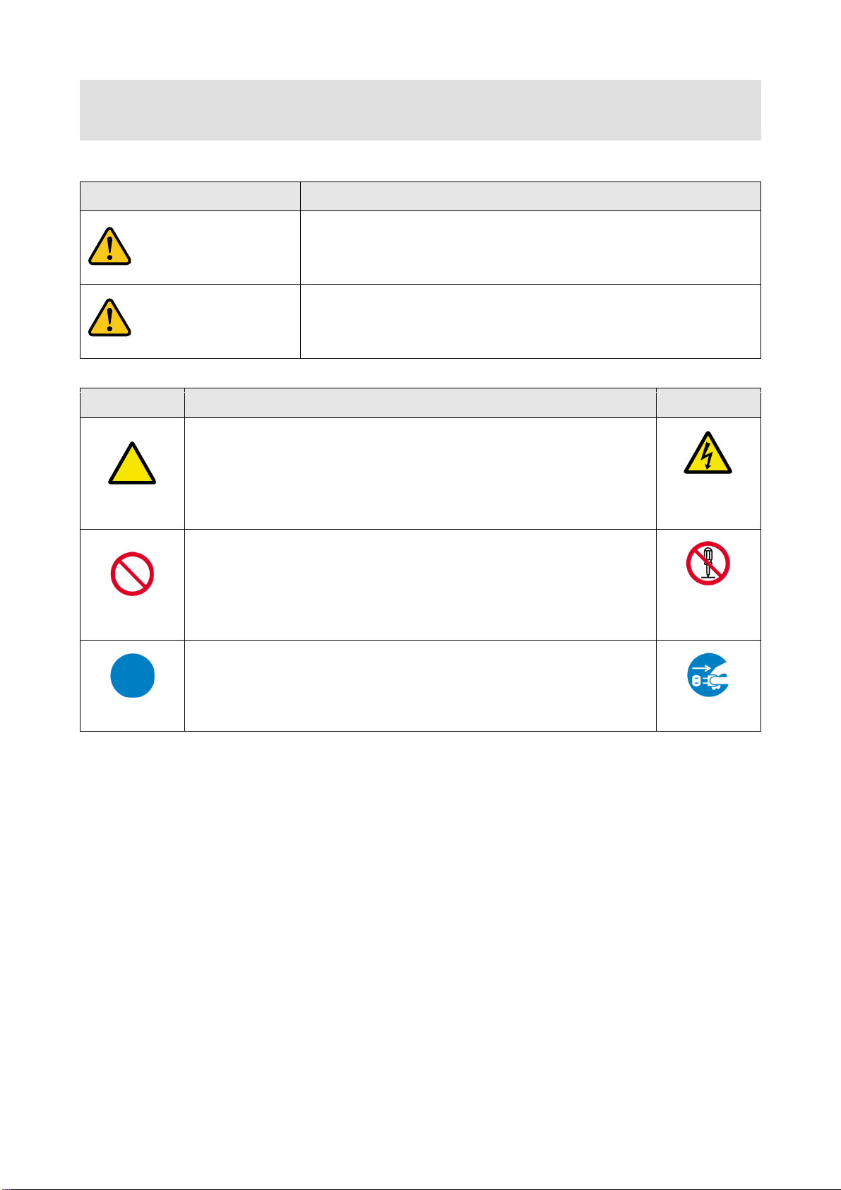
Enforcement Symbol
Description
Indicates the presence of a hazard that may result in death or serious
personal injury if the warning is ignored or the equipment is handled
incorrectly.
Indicates the presence of a hazard that may cause minor personal
injury or property damage if the caution is ignored or the equipment is
handled incorrectly.
Symbol
Description
Example
Caution
This symbol is indicated to alert the user. (Warning and caution)
Electrical
Hazard
Prohibition
This symbol is intended to prohibit the user from actions.
Do not
disassemble
Instruction
This symbol is intended to instruct the user.
Unplug
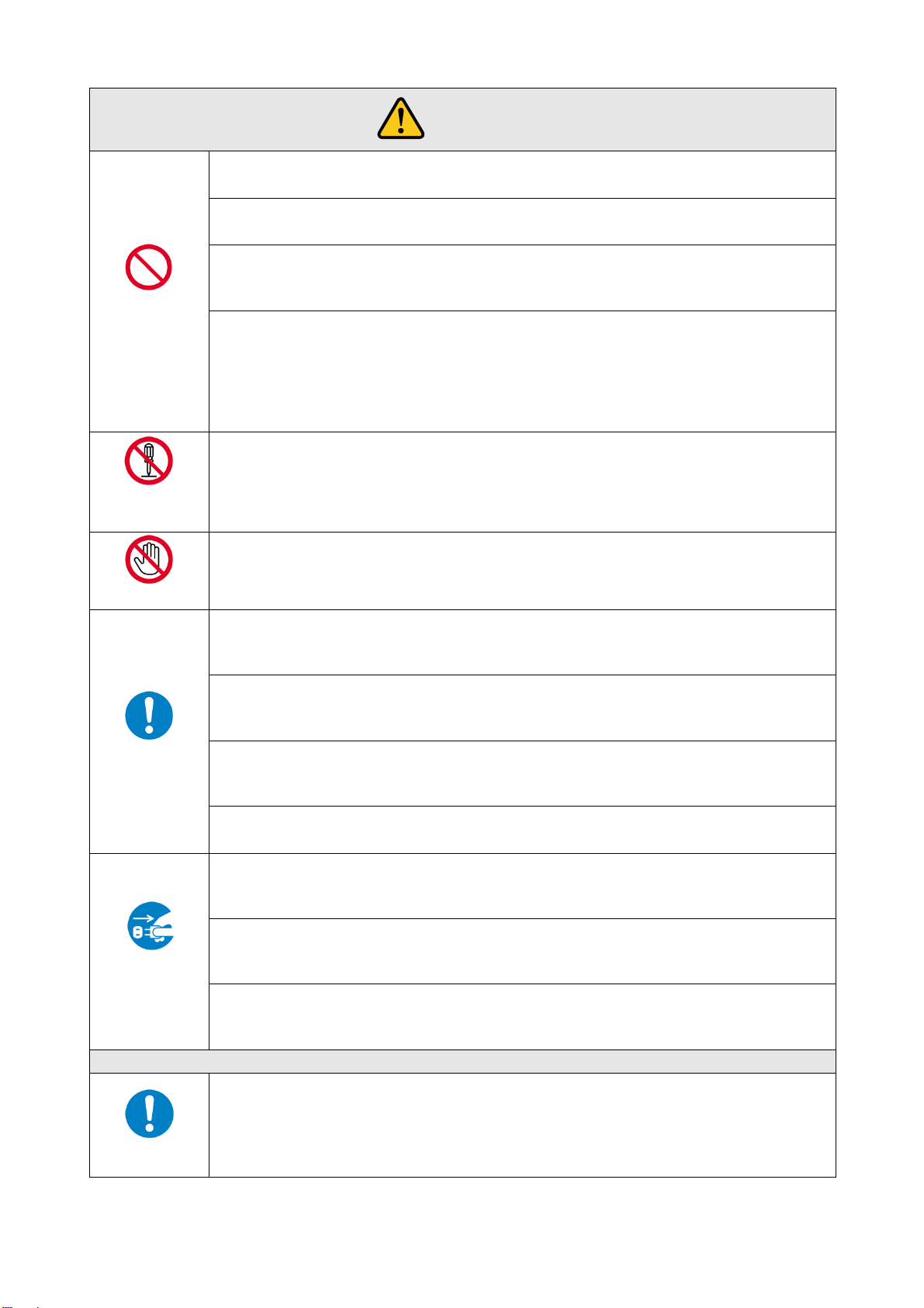
Caution
Warning
Read and understand all safety and operating instructions before using this device. Follow all instructions and
cautions as detailed in this document.
4
FDX-64 Users Guide
Prohibition
Do not place the product in any unstable place.
Install the product to a horizontal and stable place. Otherwise, it may fall/turn over and lead to injury.
Do not place the product in any environment with vibration.
Otherwise, it may move/fall and lead to injury.
Keep out any foreign objects.
In order to avoid fire or electric shock, do not allow foreign objects, such as metal and paper, to enter the product
from the vent holes.
For power cable/ plug:
・ Do not scratch, heat, or modify, including extending them.
・ Do not pull, put heavy stuff on them, or pinch them.
・ Do not bend, twist, or tie them together forcefully.
If they are used in those states continuously, it may cause fire or electric shock. If power cables/plugs become
damaged, contact IDK.
Do not
disassemble
Do not repair, modify or disassemble.
Since the product includes high-voltage parts, those actions may cause fire or electric shock. For internal
inspections or repairs, contact IDK.
Do not touch
In the event of lighting or thunder, do not touch the main unit or cables such as
power cable and LAN cable.
Contact may cause electric shock
Instruction
For installation:
The product is intended to be installed by skilled technicians. For installation, please contact a system integrator
or IDK. Otherwise, it may cause fire, electric shock, injury, or property damage.
Set the power plug in a convenient place to unplug easily.
You can easily unplug in case of any extraordinary failure or abnormal situation, and it also helps for unplugging
when you do not use it for a long period.
Plug the power plug into appropriate outlet completely.
If the plug is plugged incompletely, it may overheat which causes electrical shock or fire. Do not use damaged
plug or loosened outlet.
Clean the power plug regularly.
If the plug is covered in dust, it may cause fire due to reduced insulating power.
Unplug
Unplug immediately if the product smokes, makes unusual noise, or smells.
If you continue to use the product under those situations, it may cause electric shock or fire. After confirming that
the product stops smoking, contact IDK.
Unplug immediately if you drop the product or if the cabinet is damaged.
If you continue to use the product under those situations, it may cause electrical shock or fire. For maintenance
and repair, contact IDK.
Unplug immediately if water or other objects are directed inside.
If you continue to use it under those situations, it may cause electrical shock or fire. For maintenance and repair,
contact IDK.
For connection
Instruction
Differences in ground potential among the product and peripheral devices may cause electric shock or damage
of the devices. When using cables to connect devices, including connection of long-distance transmission,
unplug the power cables of all related devices.
After connecting signal/control cables of each device, plug in the power cables of each device.
Warning
5
FDX-64 User’s Guide
For installation
Instruction
Mount the product to the rack meeting EIA standards, and maintain spaces above and
below for air cooling. For your safety, attach an L-shape bracket in addition to the mount
bracket kit for the front panel in order to balance the weight.
Instruction
Never insert only the screws into the holes after removing the rubber feet. It may lead to
damage when the screws contact electrical circuit or parts inside of the product.
To put the rubber feet back on, use only provided rubber feet and screws.
Electrical Hazard
Double Pole/Neutral Fusing.
Prohibition
Do not place the product in any place where it will be subjected to high
temperatures.
If the product is subjected to direct sunlight or high temperatures, it may cause fire.
Do not place the product in humid, oil smoke, or dusty place.
If the product is placed near humidifiers or dusty area, it may cause fire or electric shock.
Do not block the vent holes.
If ventilation slots are blocked, it may cause fire or failure due to internal heat.
Do not put heavy items on the product.
It may fall/turn over and lead to injury.
Do not exceed ratings of outlet and wiring devices.
If several plugs are put in an outlet, it may cause fire and electric shock.
Use only the provided AC adapter and power cable.
Do not use the provided AC adapter and power cable with other products.
If non-compliant adapter or power cables is used, it may cause fire or electrical shock. Use the provided AC
power connection cable. If you want to use your product in other countries that use different AC power cables,
contact IDK.
No wet hands
Do not plug or unplug with wet hands.
It may cause electrical shock.
Instruction
Use and store the product within the specified temperature/humidity range.
If the product is used outside the range continuously, it may cause fire or electric shock.
Turn off devices when they are connected to another device.
It may cause fire or electric shock.
Unplug
Unplug the power plug if you do not use the product for a long period.
In case of defect, it may cause fire.
Unplug the power plug before cleaning.
It may cause electric shock.
Caution
For rack mount devices:
For devices with rubber feet:
Altitude:
6
Instruction
Do not place the product at elevations of 2,000 meters (6562 feet) or higher above sea
level. Failure to do so may shorten the life of the internal parts and result in malfunctions.
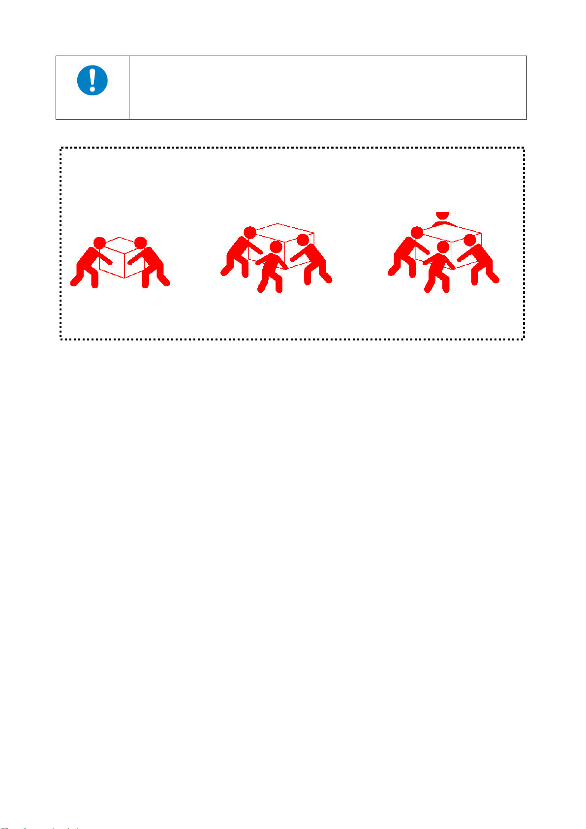
Caution:
If you lift the FDX with your knees straight fully, your back may be damaged.
When lifting the FDX, please bend your knees and get close to the machine with the following number of
persons. If you do not follow this instruction, you may be injured or the FDX may be damaged.
Over 20kg (44 lbs) Over 30kg (66 lbs) Over 50kg (110 lbs)
FDX-64 Users Guide
7

FDX-64 User’s Guide
Table of Contents
1 Included items .....................................................................................................................................10
2 Product outline ....................................................................................................................................11
3 Features ..............................................................................................................................................13
4 Panels .................................................................................................................................................15
4.1 Front panel ...................................................................................................................................15
4.2 Rear panel ...................................................................................................................................16
5 Connecting external devices ................................................................................................................18
5.1 Preparation ..................................................................................................................................18
5.2 Precautions before connection .....................................................................................................19
5.3 Connection ...................................................................................................................................21
6 Basic operation....................................................................................................................................22
6.1 Selecting Input/output channel......................................................................................................22
6.2 Menu operation key ......................................................................................................................24
6.3 Loading preset memory ................................................................................................................25
6.4 Initialization ..................................................................................................................................26
6.5 Setting/Releasing key lock............................................................................................................27
7 Menus .................................................................................................................................................28
7.1 Menu list ......................................................................................................................................29
7.2 Displaying I/O channel status [CROSS POINT].............................................................................31
7.2.1 Displaying current I/O channel status [CHANNEL DISPLAY] .................................................31
7.3 Setting input [INPUT SETTING] ....................................................................................................32
7.3.1 [INPUT EQUALIZER] ................................................................................................ ............32
7.3.2 No-signal input monitoring time [INPUT SIGNAL CHECK] ................................ .....................33
7.3.3 HDCP input enabled/disabled [INPUT HDCP] .......................................................................34
7.4 [OUTPUT SETTING] ....................................................................................................................35
7.4.1 Output equalizer [OUTPUT EQUALIZER] ..............................................................................35
7.4.2 Output mode [OUTPUT MODE] ............................................................................................35
7.4.3 Forced HDMI signal output [OUTPUT HDMI MODE] .............................................................36
7.4.4 Time for ignoring video output request signals [OUTPUT HPD MASK] ..................................36
7.4.5 Output stable level [OUTPUT STB LEVEL]............................................................................37
7.4.6 Output wait [OUTPUT WAIT SELECT] ..................................................................................37
7.5 [AUDIO] .......................................................................................................................................38
7.5.1 Digital audio output [AUDIO DIGITAL OUT] ...........................................................................38
7.6 [EDID] ..........................................................................................................................................39
7.6.1 EDID resolution [EDID DATA] ...............................................................................................40
7.6.2 Copying EDID [EDID SAVE]..................................................................................................42
7.6.3 Loading EDID channel [EDID EXTERNAL CH] ......................................................................42
7.6.4 Deep Color [EDID DEEP COLOR] ........................................................................................43
7.6.5 Audio channel [EDID SPEAKER CH] ....................................................................................44
7.6.6 Linear PCM Audio [EDID LINEAR PCM] ...............................................................................45
7.6.7 AC-3 Dolby Digital Audio [EDID AC-3/Dolby D] .....................................................................45
7.6.8 AAC Audio [EDID AAC] .........................................................................................................46
7.6.9 Dolby Digital Plus Audio [EDID Dolby D+] .............................................................................46
7.6.10 DTS Audio [EDID DTS] .........................................................................................................47
7.6.11 DTS-HD Audio [EDID DTS-HD] .............................................................................................48
8

FDX-64 Users Guide
7.6.12 Dolby TrueHD Audio [EDID Dolby TrueHD] ...........................................................................49
7.6.13 WXGA [EDID WXGA SELECT] .............................................................................................49
7.7 Setting RS-232C communication [COM PORT] ............................................................................50
7.7.1 RS-232C communication [COM PORT SETUP] ....................................................................50
7.8 LAN communication [LAN]............................................................................................................51
7.8.1 [IP ADDRESS] ......................................................................................................................51
7.8.2 [SUBNET MASK] ..................................................................................................................51
7.8.3 TCP port number [CONTROL PORT] ................................ .................................................... 52
7.8.4 Displaying MAC address [MAC ADDRESS] ...........................................................................52
7.9 Setting preset memory [PRESET MEMORY] ................................................................................53
7.9.1 Loading preset memory [PRESET LOAD] .............................................................................53
7.9.2 Saving preset memory [PRESET SAVE] ...............................................................................54
7.9.3 Editing preset memory [PRESET EDIT].................................................................................55
7.9.4 I/O channel at start-up [PRESET START UP] ........................................................................56
7.10 Setting other functions [OTHERS] ................................................................................................57
7.10.1 Grouping keys for key lock [KEY LOCK] ................................................................................57
7.10.2 Beep sound [BUZZER] ..........................................................................................................57
7.10.3 Power saving [POWER SAVE] ..............................................................................................58
7.10.4 Compatible-mode communication command [COMMAND FORMAT] ....................................58
7.10.5 [ALARM] ...............................................................................................................................59
7.10.6 Top page[TOP DISPLAY] ......................................................................................................60
7.10.7 Displaying input signal status [INPUT STATUS] ....................................................................62
7.10.8 Displaying sink device status [MONITOR STATUS] ...............................................................62
7.10.9 Displaying slot board status [BOARD STATUS] .....................................................................62
7.10.10 Displaying cooling fan status [FAN STATUS] ................................................................ .....63
7.10.11 Displaying supply voltage status [POWER STATUS] .........................................................64
7.10.12 Displaying firmware and hardware versions [VERSION] ....................................................65
8 WEB browser ......................................................................................................................................66
9 Specification ........................................................................................................................................69
9.1 Pin assignments ........................................................................................................................... 69
9.1.1 DVI-I connector .....................................................................................................................69
9.1.2 RJ-45 connector ...................................................................................................................69
9.2 Product specification ....................................................................................................................70
10 Troubleshooting ...............................................................................................................................75
9
1 Included items
DIGITAL MATRIX SWITCHER
FDX-64
POWER
SET
OUTPUT
ALL
INPUT
OFF
987
654
0
321
LOAD
PRESET
MENU
/SET
ESC
V&A VIDEO AUDIO
SWITCHING MODE
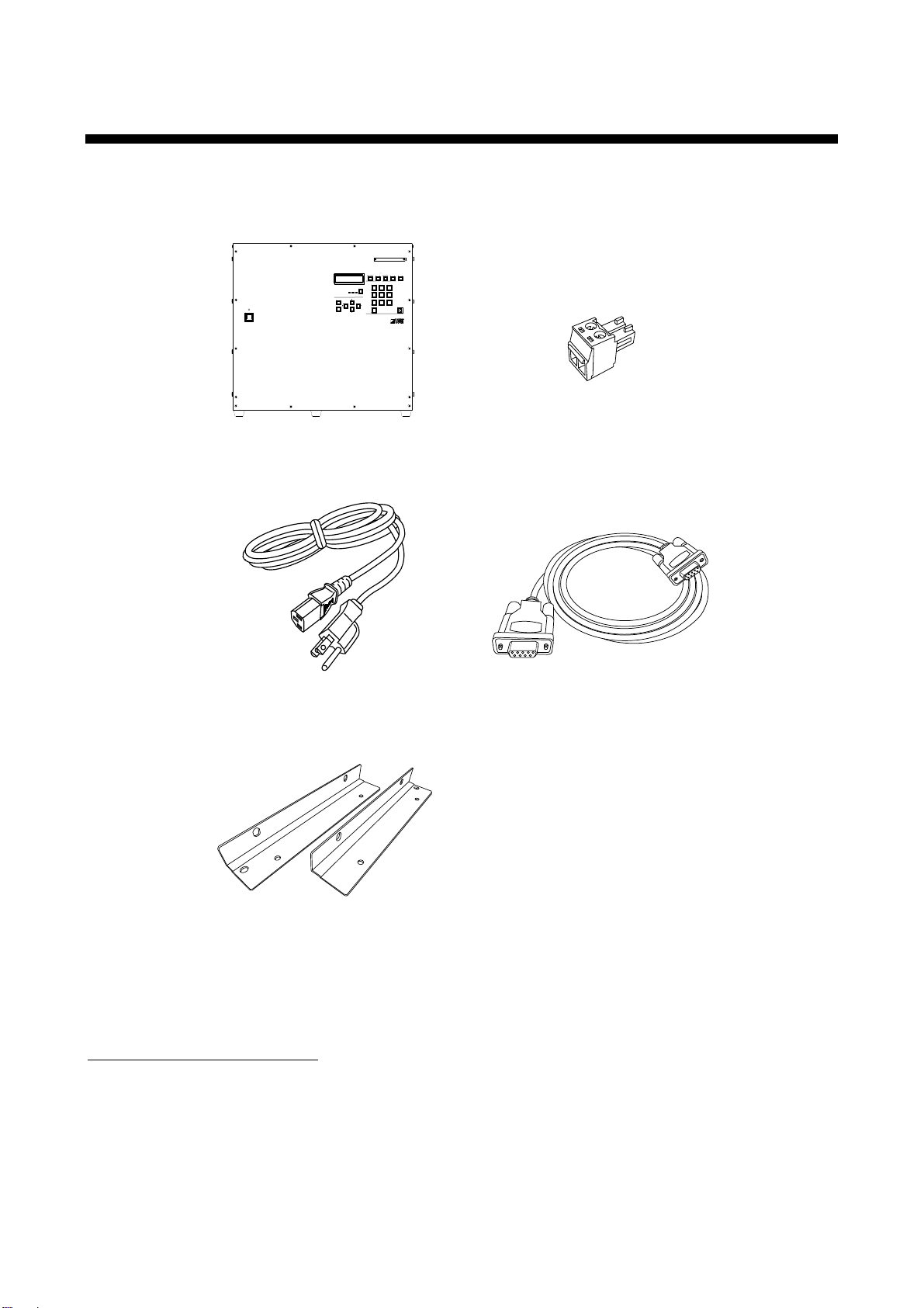
FDX-64 main unit x 1
Terminal block (2 pin) x 1
Power cable (1.8m/5.9 feet) x1
RS-232C cable (1.8 m/5.9 feet) x 1
Rack mounting bracket x 2
Make sure all items below are included in the package.
If any items are missing or damaged, please contact IDK.
FDX-64 User’s Guide
You can download the latest version of the User’s Guide from IDK’s website at:
http://www.idk.co.jp/en/index.html
10
[Fig. 1.1] Included items

FDX-64 Users Guide
Video/Audio
matrix
switch
64IN-64OUT
FDX-64
inputs/ 1 slot board
4
Digital input slot board
inputs/ 1 slot board
4
HDBaseT input slot board
outputs/ 1 slot board
HDBaseT output slot board
4
outputs/ 1 slot board
Digital input slot board
4
Digital video/audio
for extension
HDBaseT
I/O slot board can be added by 4 inputs or 4 outputs.
Digital video/audio
for extension
HDBaseT
Max. extension
100 m/ 328.08 ft.
Receiver
EDID emulator
Input EQ
Transmitter
Max. extension
Output EQ
Digital video/audio
for extension
Optical fiber
Max. extension
Multimode fiber
OM3: 300 m/ 984.25 ft.
OM4: 1 km/ 3280.83 ft.
inputs/ 1 slot board
4
Optical input slot board
outputs/ 1 slot board
Optical output slot board
4
TransmitterReceiver
EDID emulator
Singlemode fiber
OS1 4.7 km/
15419.95 ft.
Digital video/audio
for extension
Optical fiber
Max. extension
30 m/ 98.43 ft.
Max. extension
40 m/ 131.23 ft.
Up to outputs/ 16 slot boards
64
Up to inputs/ 16 slot boards
64
Digital video/audio
HDMI DVI
Digital video/audio
HDMI DVI
EDID emulator
100 m/ 328.08 ft.
Max. extension
Multimode fiber
OM3: 300 m/ 984.25 ft.
OM4: 1 km/ 3280.83 ft.
Singlemode fiber
OS1: 4.7 km/
15419.95 ft.
2 Product outline
Caution: The FDX-64 outputs continuous invisible light, which may be harmful to your eyes. Please follow the
following cautions.
● Do not look into the rear panel fiber optic cable connectors or into the fiber optic cables
themselves.
● Plug the attached dust caps into the optical transceivers when the fiber cable is unplugged.
FDX-64 has 64 inputs and 64 outputs. Since this HDMI/DVI Digital Matrix Switcher supports HDCP, video
whose copyright is protected, such as Blu-ray, can be input. HDMI signals can also be input via a conversion
cable.
Combining HDBaseT or optical I/O slot board that supports a long-distance extension enables simple
configurations around the matrix switcher.
The FDX has RS-232C and LAN as its communication ports for external control so that you can control each
setting remotely.
● Digital input slot board (4 inputs)
Four DVI-I connectors are mounted that can input both HDMI (a conversion cable is needed) and DVI
signals.
● HDBaseT input slot board (4 inputs)
● Optical input slot board (4 inputs)
Four RJ-45 connectors are mounted that can extend digital (video/audio) signals up to 100 m/328.08 ft.
when the HDC-T series and FDX series are used together.
Up to four SFP (LC connector x 2) modules can be mounted. Digital signals can be extended up to 4.7
km/15419.95 ft. (singlemode fiber) when the OPF-TH1000 and FDX are used together.
● Digital output slot board (4 outputs)
Four DVI-I connectors that are mounted can output video and audio signals of the selected input
channel.
[Fig. 2.1] I/O diagram
11

● HDBaseT output slot board (4 outputs)
Four RJ-45 connectors are mounted that can output video and audio signals of the selected input
channel. Those digital (video/audio) signals can be extended up to 100 m/328.08 ft. when the HDC-R
series and FDX series are used together.
● Optical output slot board (4 outputs)
Up to four SFP (LC connector x 2) modules are mounted that can output video and audio signals of
the selected input channel. Those digital signals can be extended up to 4.7 km/15419.95 ft.
(singlemode fiber) when the OPF-RH1000 and FDX are used together.
FDX-64 User’s Guide
12
~1 4
~5 8
~9 12
~13 16
~17 20
~21 24
~25 28
OUTPUT
OUTPUT
OUTPUT
OUTPUT
OUTPUT
OUTPUT
OUTPUT
OUTPUT
~29 32
A D
A D
A D
A D
A D
A D
A D
A D
INPUT
~1 4
INPUT
~5 8
INPUT
~9 12
INPUT
~13 16
INPUT
~17 20
INPUT
~21 24
INPUT
~25 28
INPUT
~29 32
A D
A D
A D
A D
A D
A D
A D
A D
INPUT
INPUT
INPUT
INPUT
INPUT
INPUT
INPUT
INPUT
~33 36
~37 40
~41 44
~45 48
A D
A D
A D
A D
~49 52
~53 56
~57 60
~61 64
A D
A D
A D
A D
~33 36
~37 40
~41 44
OUTPUT
OUTPUT
OUTPUT
OUTPUT
~45 48
A D
A D
A D
A D
~49 52
~53 56
~57 60
OUTPUT
OUTPUT
OUTPUT
OUTPUT
~61 64
A D
A D
A D
A D
FG
AC 100-240V
50/60Hz
S/N
OPTION
RS-232C
LAN
ALARM
BREAKERPOWER
DVI-D(HDMI) DVI-D(HDMI) DVI-D(HDMI) DVI-D(HDMI)
A B C D
DVI-D(HDMI) DVI-D(HDMI) DVI-D(HDMI) DVI-D(HDMI)
A B C D
DVI-D(HDMI) DVI-D(HDMI) DVI-D(HDMI) DVI-D(HDMI)
A B C D
DVI-D(HDMI) DVI-D(HDMI) DVI-D(HDMI) DVI-D(HDMI)
A B C D
DVI-D(HDMI) DVI-D(HDMI) DVI-D(HDMI) DVI-D(HDMI)
A B C D
DVI-D(HDMI) DVI-D(HDMI) DVI-D(HDMI) DVI-D(HDMI)
A B C D
DVI-D(HDMI) DVI-D(HDMI) DVI-D(HDMI) DVI-D(HDMI)
A B C D
DVI-D(HDMI) DVI-D(HDMI) DVI-D(HDMI) DVI-D(HDMI)
A B C D
DVI-D(HDMI) DVI-D(HDMI) DVI-D(HDMI) DVI-D(HDMI)
A B C D
DVI-D(HDMI) DVI-D(HDMI) DVI-D(HDMI) DVI-D(HDMI)
A B C D
DVI-D(HDMI) DVI-D(HDMI) DVI-D(HDMI) DVI-D(HDMI)
A B C D
DVI-D(HDMI) DVI-D(HDMI) DVI-D(HDMI) DVI-D(HDMI)
A B C D
A
RX TX RX TX RX TX RX TX
B C D
OPTICAL OPTICAL OPTICAL OPTICAL
A
RX TX RX TX RX TX RX TX
B C D
OPTICAL OPTICAL OPTICAL OPTICAL
A
RX TX RX TX RX TX RX TX
B C D
OPTICAL OPTICAL OPTICAL OPTICAL
A
RX TX RX TX RX TX RX TX
B C D
OPTICAL OPTICAL OPTICAL OPTICAL
A
RX TX RX TX RX TX RX TX
B C D
OPTICAL OPTICAL OPTICAL OPTICAL
A
RX TX RX TX RX TX RX TX
B C D
OPTICAL OPTICAL OPTICAL OPTICAL
A
RX TX RX TX RX TX RX TX
B C D
OPTICAL OPTICAL OPTICAL OPTICAL
A
RX TX RX TX RX TX RX TX
B C D
OPTICAL OPTICAL OPTICAL OPTICAL
UPDATE 1UPDATE 2
LINK LINK LINK LINK
HDBaseTA B C DHDBaseT HDBaseT HDBaseT
LINK LINK LINK LINK
HDBaseTA B C DHDBaseT HDBaseT HDBaseT
LINK LINK LINK LINK
HDBaseTA B C DHDBaseT HDBaseT HDBaseT
LINK LINK LINK LINK
HDBaseTA B C DHDBaseT HDBaseT HDBaseT
LINK LINK LINK LINK
HDBaseTA B C DHDBaseT HDBaseT HDBaseT
LINK LINK LINK LINK
HDBaseTA B C DHDBaseT HDBaseT HDBaseT
LINK LINK LINK LINK
HDBaseTA B C DHDBaseT HDBaseT HDBaseT
LINK LINK LINK LINK
HDBaseTA B C DHDBaseT HDBaseT HDBaseT
LINK LINK LINK LINK
HDBaseTA B C DHDBaseT HDBaseT HDBaseT
LINK LINK LINK LINK
HDBaseTA B C DHDBaseT HDBaseT HDBaseT
LINK LINK LINK LINK
HDBaseTA B C DHDBaseT HDBaseT HDBaseT
LINK LINK LINK LINK
HDBaseTA B C DHDBaseT HDBaseT HDBaseT
3 Features
FDX-64 Users Guide
■ For video
・The maximum resolution: QWXGA
1
*
(RB)
2
*
, 1080p
・Digital cable equalizer function (digital I/O slot board)
Input: Up to 10 m to 30 m/32.8 to 98.43 ft.
Output: Up to 10 m to 40 m/32.8 to 131.23 ft.
・Extension: Up to 100 m/328.08 ft. via a Cat6 cable (HDBaseT I/O slot board)
・Long-distance transmission via an optical fiber cable (Optical I/O slot board)
Multimode fiber (OM 3): Up to 300 m/984.25 ft.
Multimode fiber (OM 4): Up to 1 km/3280.83 ft.
Singlemode fiber (OS 1): Up to 4.7 km/15419.95 ft.
・Anti-snow
・The number of inputs and outputs can be customized using 4 channels.
■ Control input: RS-232C, LAN
[Fig. 3.1] Example of slot board combination
13

FDX-64 User’s Guide
■ Others
● EDID emulation (with copy function)
● Switching video and audio separately (when optional Audio unit*3 is connected)
● I/O slot board, CPU slot board, and fan unit can be replaced without removing from the rack.
● Alarm output (Monitoring power and fans)
● Start-up memory
● Preset memory
● Last memory
● Connection reset
● Key lock
● Redundant power supply (optional extra)
*1 The maximum resolution of optical I/O slot board: WUXGA (RB)
*2 (RB): Reduced Blanking
*3 Audio unit: Use MAL-64-B for audio L; MAR-64-B for Audio R
*4 (RB): Reduced Blanking
14
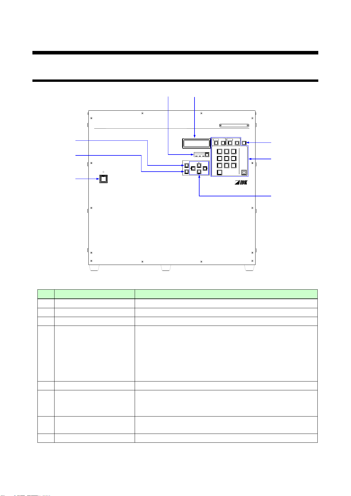
DIGITAL MATRIX SWITCHER
FDX-64
POWER
SET
OUTPUT
ALL
INPUT
OFF
987
654
0
321
LOAD
PRESET
MENU
/SET
ESC
V&AVIDEOAUDIO
SWITCHING MODE
①
②
③
④
⑤
⑥
⑦
⑧
#
Part name
Description
①
MENU/SET key
Displays menus and edits/controls settings.
②
ESC key
Goes back to the previous page.
③
Arrow keys (▲, ▼, ◄, ►)
Switches menus, moves cursors and changes set values.
④
I/O channel selection keys
0 to 9: Selects numbers.
SET: Applies the I/O channel setting.
INPUT: Moves the cursor to the INPUT side.
OFF: Selects “OFF” (no signal) of input channel.
OUTPUT: Moves the cursor to the OUTPUT side.
ALL: Selects all output channels.
⑤
Loading preset memory key
Displays the preset memory screen.
⑥
SWITCHING MODE key
V&A: Switching the FDX and Audio unit (optional) together.
VIDEO: Switching only the FDX.
AUDIO: Switching only the Audio unit.
⑦
Power supply switch
(POWER)
Turns on/off the FDX. If the main power supply switch of the rear.
panel is turned off, this switch is invalid.
⑧
LCD screen
Displays menus and settings.
4 Panels
4.1 Front panel
FDX-64 Users Guide
[Fig. 4.1] Front panel drawing
15
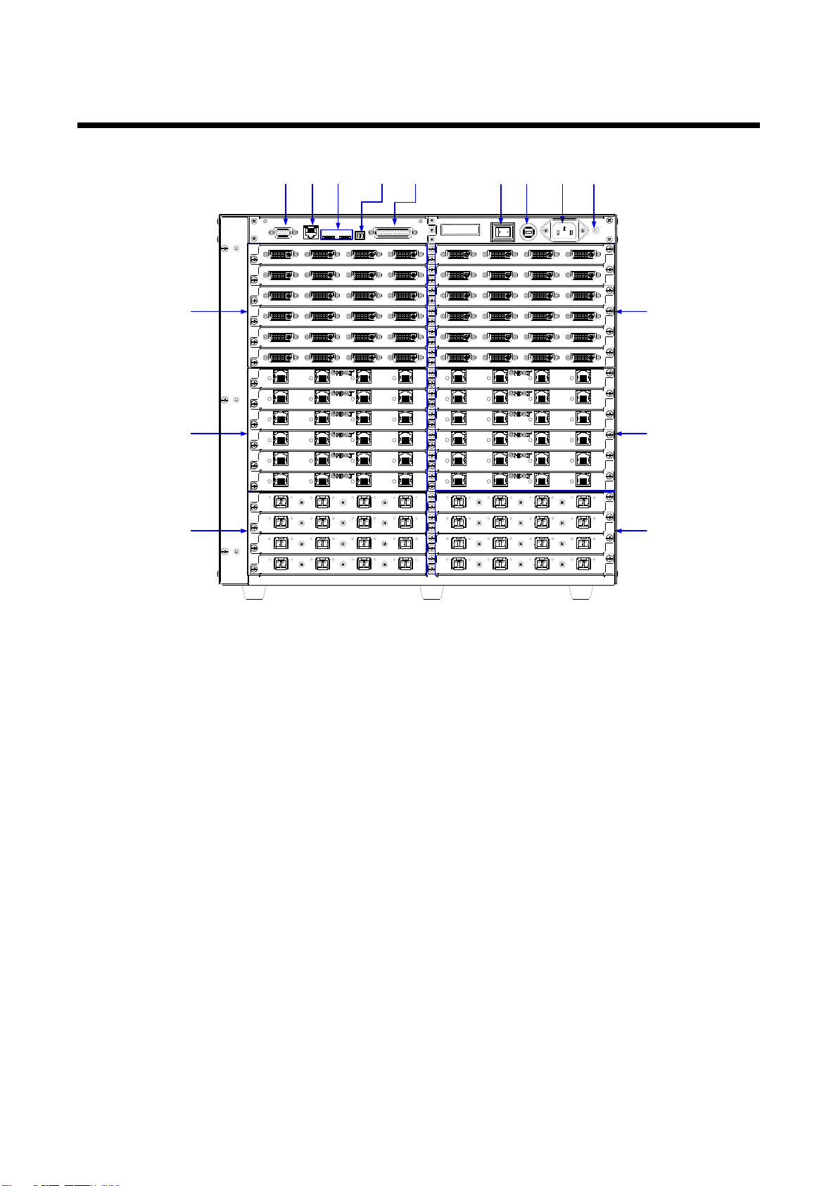
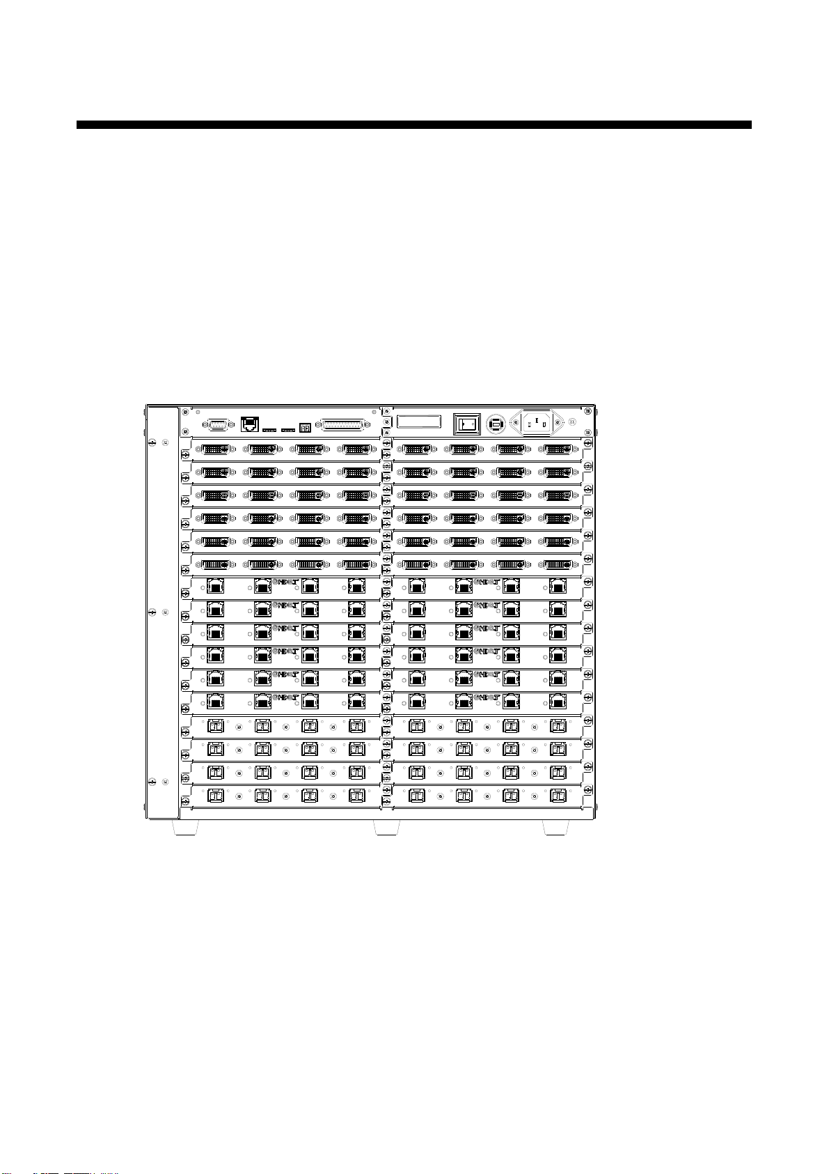
4.2 Rear panel
①
②
③
④
⑤
⑥
⑦ ⑧ ⑨ ⑩ ⑪ ⑫ ⑬ ⑭ ⑮
~1 4
~5 8
~9 12
~13 16
~17 20
~21 24
~25 28
OUTPUT
OUTPUT
OUTPUT
OUTPUT
OUTPUT
OUTPUT
OUTPUT
OUTPUT
~29 32
A D
A D
A D
A D
A D
A D
A D
A D
INPUT
~1 4
INPUT
~5 8
INPUT
~9 12
INPUT
~13 16
INPUT
~17 20
INPUT
~21 24
INPUT
~25 28
INPUT
~29 32
A D
A D
A D
A D
A D
A D
A D
A D
INPUT
INPUT
INPUT
INPUT
INPUT
INPUT
INPUT
INPUT
~33 36
~37 40
~41 44
~45 48
A D
A D
A D
A D
~49 52
~53 56
~57 60
~61 64
A D
A D
A D
A D
~33 36
~37 40
~41 44
OUTPUT
OUTPUT
OUTPUT
OUTPUT
~45 48
A D
A D
A D
A D
~49 52
~53 56
~57 60
OUTPUT
OUTPUT
OUTPUT
OUTPUT
~61 64
A D
A D
A D
A D
FG
AC 100-240V
50/60Hz
S/N
OPTION
RS-232C
LAN
ALARM
BREAKERPOWER
DVI-D(HDMI) DVI-D(HDMI) DVI-D(HDMI) DVI-D(HDMI)
A B C D
DVI-D(HDMI) DVI-D(HDMI) DVI-D(HDMI) DVI-D(HDMI)
A B C D
DVI-D(HDMI) DVI-D(HDMI) DVI-D(HDMI) DVI-D(HDMI)
A B C D
DVI-D(HDMI) DVI-D(HDMI) DVI-D(HDMI) DVI-D(HDMI)
A B C D
DVI-D(HDMI) DVI-D(HDMI) DVI-D(HDMI) DVI-D(HDMI)
A B C D
DVI-D(HDMI) DVI-D(HDMI) DVI-D(HDMI) DVI-D(HDMI)
A B C D
DVI-D(HDMI) DVI-D(HDMI) DVI-D(HDMI ) DVI-D(HDMI)
A B C D
DVI-D(HDMI) DVI-D(HDMI) DVI-D(HDMI ) DVI-D(HDMI)
A B C D
DVI-D(HDMI) DVI-D(HDMI) DVI-D(HDMI ) DVI-D(HDMI)
A B C D
DVI-D(HDMI) DVI-D(HDMI) DVI-D(HDMI ) DVI-D(HDMI)
A B C D
DVI-D(HDMI) DVI-D(HDMI) DVI-D(HDMI ) DVI-D(HDMI)
A B C D
DVI-D(HDMI) DVI-D(HDMI) DVI-D(HDMI ) DVI-D(HDMI)
A B C D
A
RX TX RX TX RX TX RX TX
B C D
OPTICAL OPTICAL OPTICAL OPTICAL
A
RX TX RX TX RX TX RX TX
B C D
OPTICAL OPTICAL OPTICAL OPTICAL
A
RX TX RX TX RX TX RX TX
B C D
OPTICAL OPTICAL OPTICAL OPTICAL
A
RX TX RX TX RX TX RX TX
B C D
OPTICAL OPTICAL OPTICAL OPTICAL
A
RX TX RX TX RX TX RX TX
B C D
OPTICAL OPTICAL OPTICAL OPTICAL
A
RX TX RX TX RX TX RX TX
B C D
OPTICAL OPTICAL OPTICAL OPTICAL
A
RX TX RX TX RX TX RX TX
B C D
OPTICAL OPTICAL OPTICAL OPTICAL
A
RX TX RX TX RX TX RX TX
B C D
OPTICAL OPTICAL OPTICAL OPTICAL
UPDATE 1UPDATE 2
LINK LINK LINK LINK
HDBaseTA B C DHDBaseT HDBaseT HDBaseT
LINK LINK LINK LINK
HDBaseTA B C DHDBaseT HDBaseT HDBaseT
LINK LINK LINK LINK
HDBaseTA B C DHDBaseT HDBaseT HDBaseT
LINK LINK LINK LINK
HDBaseTA B C DHDBaseT HDBaseT HDBaseT
LINK LINK LINK LINK
HDBaseTA B C DHDBaseT HDBaseT HDBaseT
LINK LINK LINK LINK
HDBaseTA B C DHDBaseT HDBaseT HDBaseT
LINK LINK LINK LINK
HDBaseTA B C DHDBaseT HDBaseT HDBaseT
LINK LINK LINK LINK
HDBaseTA B C DHDBaseT HDBaseT HDBaseT
LINK LINK LINK LINK
HDBaseTA B C DHDBaseT HDBaseT HDBaseT
LINK LINK LINK LINK
HDBaseTA B C DHDBaseT HDBaseT HDBaseT
LINK LINK LINK LINK
HDBaseTA B C DHDBaseT HDBaseT HDBaseT
LINK LINK LINK LINK
HDBaseTA B C DHDBaseT HDBaseT HDBaseT
FDX-64 User’s Guide
16

FDX-64 Users Guide
#
Part name
Description
①
DVI input connectors
(DVI-D HDMI)
For DVI-I cables and DVI-D cables (analog signals cannot be used).
HDMI signals can be input using an HDMI-DVI conversion cable.
②
HDBaseT input ports
(HDC)
Digital (video/audio) signals can be extended up to 100 m/328.08 ft.
using the HDC transmitter and FDX together.
③
Optical input ports
(OPTICAL)
Digital (video/audio) signals can be extended up to 4.7 km/
2.9 miles (singlemode fiber) using the OPF-TH1000 and FDX
together.
④
DVI output connectors
(DVI-D HDMI)
For DVI-I cables and DVI-D cables (analog signals cannot be used).
HDMI signals can be input using an HDMI-DVI conversion cable.
⑤
HDBaseT output ports
(HDC)
Digital (video/audio) signals can be extended up to 100 m/328.08 ft.
using the HDC receiver and FDX together.
⑥
Optical output ports
(OPTICAL)
Digital (video/audio) signals can be extended up to 4.7 km/2.9 miles
(singlemode fiber) using the OPF-RH1000 and FDX together.
⑦
RS-232C port (RS-232C)
For external control using communication commands.
⑧
LAN port (LAN)
For external control by communication commands or web browsers.
⑨
Maintenance port
(UPDATE)
Not used. Keep this connector free.
⑩
ALARM port (ALARM)
When the FDX detects an serious problem (alarm), the relay contact
will be closed.
⑪
Option port (OPTION)
If the Audio unit (optional) is used, use the special cable. Normally,
please do not connect anything.
⑫
Main power switch
(POWER)
Turns on/off the FDX.
⑬
BREAKER
Turned OFF if a circuit is broken or a problem in circuit parts
appears for some reason in order to prevent overcurrent into the
FDX. If the breaker is turned off, press the breaker. However, if the
breaker is turned off again, problems may have occurred in the
device. Please contact us.
⑭
AC power connector
For the provided power cable.
⑮
Frame ground (FG)
For indoor ground terminal. An M4 screw is used.
17
FDX-64 User’s Guide
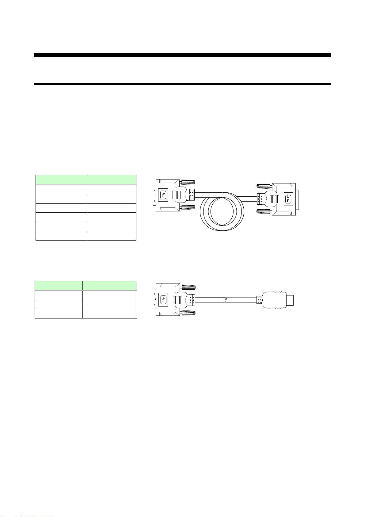
Part number
Length
CBL-DH-015A
1.5 m/4.92 ft.
CBL-DH-03A
3 m/9.84 ft.
CBL-DH-05A
5 m/16.4 ft.
Part number
Length
DVIP/DVIP-S10
10 m/32.8 ft.
DVIP/DVIP-S15
15 m/19.21 ft.
DVIP/DVIP-S20
20 m/65.62 ft.
DVIP/DVIP-S30
30 m/98.43 ft.
DVIP/DVIP-S40
40 m/131.23 ft.
DVIP/DVIP-S50
50 m/164.04 ft.
5 Connecting external devices
5.1 Preparation
Prepare necessary cables before connecting external devices such as source and sink devices.
● For digital I/O slot board: DVI cable
● For HDBaseT I/O slot board: HDBaseT cable
● Optical I/O slot board: Optical fiber cable
■ DVI cable
For DVI input and output, please use a single-link cable of DVI-I or DVI-D (male connector). Analog
signals cannot be input or output, and dual link is not supported. If you use a 5 m/16.4 ft. or longer cable
for input or output, please use an IDK’s cable (AWG24).
[Fig. 5.1] Single sink long cable
For HDMI connectors, please use one of the following conversion cables.
[Fig. 5.2] Conversion cable (HDMI-DVI conversion)
Note: Since DVI signals are very fast, use a cable meeting the DVI Rev1.0 standard. (IDK’s cables meet the
standard.)
■ HDBaseT cable
Use a UTP/STP cable meeting Cat5e/Cat6 standard.
■ Optical fiber cable
Use a duplex fiber whose both sides have a LC connector or two simplex fibers. The length of the cable
must meet the standard of the extended distance.
18

FDX-64 Users Guide
5.2 Precautions before connection
■ For installation
● If connecting a cable to the FDX or an external device that connected to the FDX, touch grounded metal to
remove electricity from your body before holding the cable.
● Do not block vent holes.
Keep 30 mm/1.18 inches or bigger space from the FDX.
● Do not install the FDX in a closed space.
If you must install the FDX in a closed space (EIA rack mount), install an additional ventilation space in
order to keep the ambient temperature at 40 degrees C/104 degrees F or less. If inadequately vented, the
life of parts may be shortened and operations may be affected.
■ Cabling
● Read manuals of the external devices.
● Turn off devices and then connect them.
● Be sure to plug cables in completely and install them without any stress on connectors.
■ Attaching rack mounting brackets
1. Remove two M5 screws from one side of the unit. Retain the screws for step 2.
2. Attach one bracket to the side of the unit using the screws removed in step 1.
3. Repeat steps 1 and 2 on the other side of the unit.
Note : The standard screw tightening torque is 2.94 N・m (about 30 kgf・cm).
■ HDBaseT cable <Read the following precautions when installing an HDBaseT I/O slot board.>
Even though the connector for a long-distance transmission is the same as eight-core connector that is
used for Ethernet, the transmission method is different. As a result, the connector for a long-distance
transmission cannot be connected to Ethernet.
Please use a correct HDBaseT cable and install it correctly to maximize the performance of this product.
● We recommend a Cat6 UTP/STP cable for the HDBaseT cable between the transmitter and receiver.
If using an STP cable, connect the FG connector to an earth ground source. Otherwise, the shielding
function does not work correctly. When using a UTP cable, we still recommend that you use the ground
connector.
● For 50 m/164.04 feet or shorter transmissions, Cat5e UTP/STP cable also can be used.
● The shielded STP cables are less affected by interference or external noise than UTP cables.
● The maximum extension distance of Cat5e/Cat6 UTP/STP cable is the shortest maximum extension
distance of the connected HDC transmitter, HDC receiver and sink device.
● For pin assignments, apply T568A or T568B straight through cabling.
● Do not give connection cables a strong pull. The allowable tension of the HDBaseT cable is 110 N.
● Do not bend the connection cable at a sharp angle. Keep the bend radius four times of the cable
diameter or more.
● Keep the HDBaseT cable as straight as you can. If you coil the cable, it is easily affected by noise.
● Do not tie the cable tightly; leave a space allowing the cable to move slightly.
● If you use the same cables, we recommended keeping distance between the cables or not to place
the cables closely in parallel.
● Do not place this product in an electrically noisy environment, since high-speed signals are transmitted.
Video or audio may be interrupted especially when you use a high-output radio around the FDX.
19

FDX-64 User’s Guide
Multimode fiber
Singlemode fiber
Wave length
850 nm (Oxide VCSEL laser*)
1310 nm (Fabry-Perot laser*)
Maximum extension distance
OM3: 300 m/984.25 feet
OM4: 1 km/3280.84 feet
OS1: 4.7 km/15419.94 feet
Input level
-13 dBm or higher
-18 dBm or higher
Output level
-9 dBm to -2.5 dBm
-8.4 dBm to -3 dBm
Connector
LC (Duplex)
● If the distance between the FDX and transmitter/receiver is 100 m/328.08 ft. or less, a cable joint can be
used. Up to two cable joints are allowed and joints supporting Cat6A (10GBase-T) are recommended.
Note: If there is a problem in the transmission path, video or audio may be interrupted. Please check the
items above. If the problem still cannot be resolved, shorten the length of the HDBaseT cable.
■ Optic fiber cable [Read this instruction when mounting an optical I/O slot board.]
To ensure the best performance of the FDX, select the appropriate optical fiber cable for a long- distance
transmission and connect it correctly.
● Use a duplex fiber or two simplex fiber cables with LC connectors at both ends.
To polish connectors:
For SFP module for multimode: PC polishing is recommended.
For SFP module for singlemode: UPC polishing is recommended.
Note: APC polishing is not supported.
● Make sure that the fiber optical cable to be connected between the FDX and transmitter/receiver
meets the standard of the desired extension distance.
● Extension distance varies depending on attenuation of the fiber, connector and other contact portions.
● Before inserting or removing the fiber, make sure to first turn the FDX off and not to touch the ends of
the fiber. Clean them up before inserting the cable again.
♦ Simplex fiber and duplex fiber:
Simplex fiber has an optic fiber and a connector at both ends while duplex fiber has two fibers and two
connectors. The duplex fiber cable is recommended for the FDX, but signals can be transmitted using two
simplex fiber cables.
♦ LC connector:
One of connectors for fiber optical cables. (Example: SC connector, FC connector, ST connector, MU
connector)
■ SFP module [Read this instruction when mounting an optical I/O slot board.]
The fiber type and extension distance to be used vary depending on the SFP module.
[Table 5.1] Specifications of standard SFP modules
* Some SFP modules for singlemode can extend the transmission distance up to 30 km with OS1.
Please contact us if needed.
Notes:
● Plug the dust cap to the fiber optical cable if you do not use it.
● Do not use the SFP module for other devices. Do not connect the optic fiber cable that is connected to
other devices to the SFP module; otherwise, the SFP module may be broken. The maximum receiving
optical level of the SFP module in the FDX is 0 dBm
● If you need to replace the SFP module, please contact us.
20
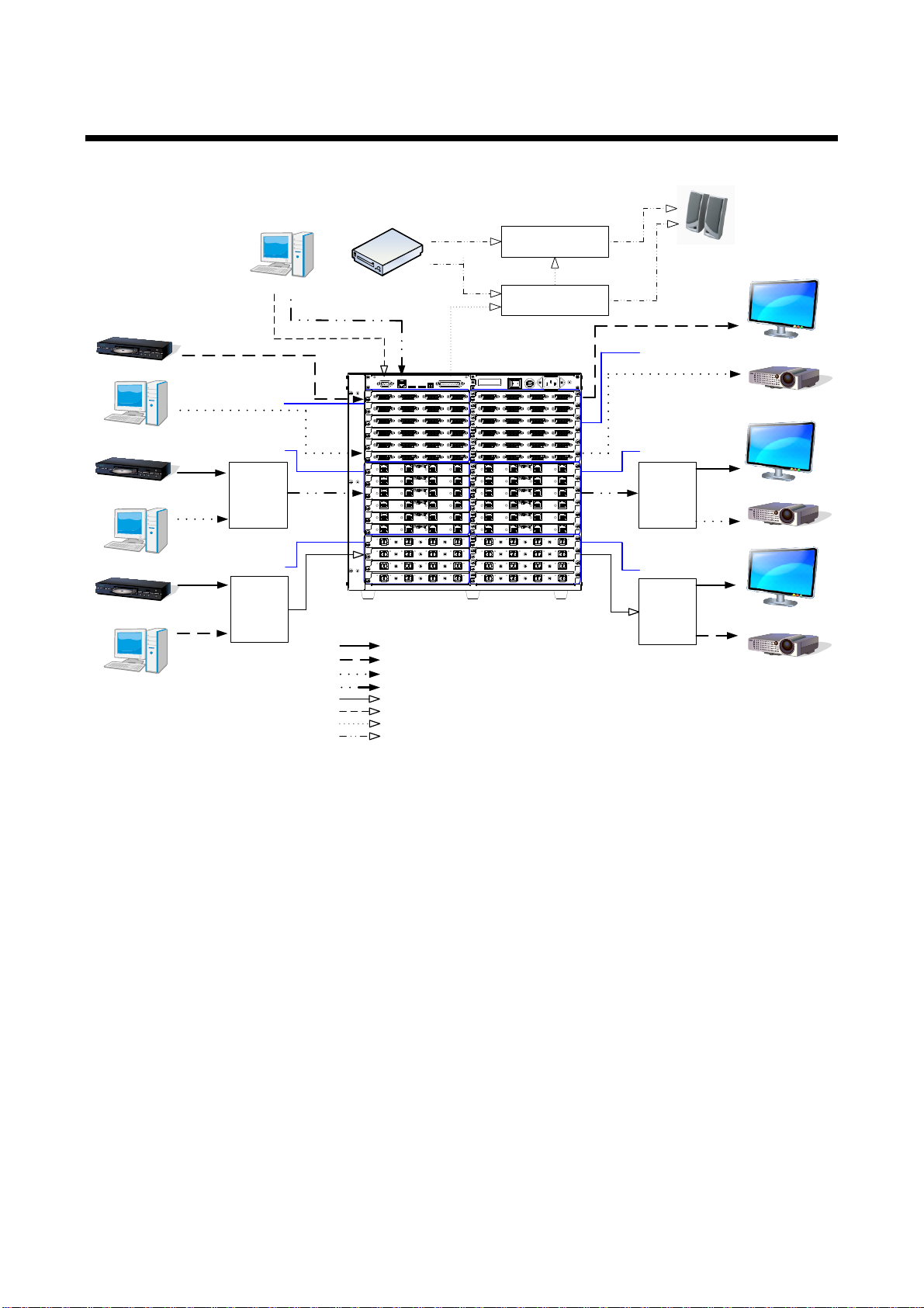
HDMI/DVI
Blu-ray player
Projector
LC monitor
PC
DVI
Digital input connection
Blu-ray player
PC
HDBaseT input connection
DVI
Blu-ray player
PC
HDMI/DVI
Optical input connection
HDMI/DVI
DVI
DVI
Projector
LC monitor
HDMI/DVI
Projector
LC monitor
Optical output connection
PC
Video/Audio input
External control
Video/Audio ouput
Speaker
Audio output
FDX-64
RS-232C
LAN
MAL-64-B
HDC series
transmitter
OPF-TH1000
Analog audio R input
Audio input
CD player
HDMI
HDMI
HDMI
HDMI
MAR-64-B
OPF-RH1 000
HDC series
receiver
~1 4
~5 8
~9 12
~13 16
~17 20
~21 24
~25 28
OUTPUT
OUTPUT
OUTPUT
OUTPUT
OUTPUT
OUTPUT
OUTPUT
OUTPUT
~29 32
A D
A D
A D
A D
A D
A D
A D
A D
INPUT
~1 4
INPUT
~5 8
INPUT
~9 12
INPUT
~13 16
INPUT
~17 20
INPUT
~21 24
INPUT
~25 28
INPUT
~29 32
A D
A D
A D
A D
A D
A D
A D
A D
INPUT
INPUT
INPUT
INPUT
INPUT
INPUT
INPUT
INPUT
~33 36
~37 40
~41 44
~45 48
A D
A D
A D
A D
~49 52
~53 56
~57 60
~61 64
A D
A D
A D
A D
~33 36
~37 40
~41 44
OUTPUT
OUTPUT
OUTPUT
OUTPUT
~45 48
A D
A D
A D
A D
~49 52
~53 56
~57 60
OUTPUT
OUTPUT
OUTPUT
OUTPUT
~61 64
A D
A D
A D
A D
FG
AC 100-240V
50/60Hz
S/N
OPTION
RS-232C
LAN
ALARM
BREAKERPOWER
DVI-D(HDMI) DVI-D(HDMI) DVI-D(HDMI) DVI-D(HDMI)
A B C D
DVI-D(HDMI) DVI-D(HDMI) DVI-D(HDMI) DVI-D(HDMI)
A B C D
DVI-D(HDMI) DVI-D(HDMI) DVI-D(HDMI) DVI-D(HDMI)
A B C D
DVI-D(HDMI) DVI-D(HDMI) DVI-D(HDMI) DVI-D(HDMI)
A B C D
DVI-D(HDMI) DVI-D(HDMI) DVI-D(HDMI) DVI-D(HDMI)
A B C D
DVI-D(HDMI) DVI-D(HDMI) DVI-D(HDMI) DVI-D(HDMI)
A B C D
DVI-D(HDMI) DVI-D(HDMI) DVI-D(HDMI) DVI-D(HDMI)
A B C D
DVI-D(HDMI) DVI-D(HDMI) DVI-D(HDMI) DVI-D(HDMI)
A B C D
DVI-D(HDMI) DVI-D(HDMI) DVI-D(HDMI) DVI-D(HDMI)
A B C D
DVI-D(HDMI) DVI-D(HDMI) DVI-D(HDMI) DVI-D(HDMI)
A B C D
DVI-D(HDMI) DVI-D(HDMI) DVI-D(HDMI) DVI-D(HDMI)
A B C D
DVI-D(HDMI) DVI-D(HDMI) DVI-D(HDMI) DVI-D(HDMI)
A B C D
A
RX TX RX TX RX TX RX TX
B C D
OPTICAL OPTICAL OPTICAL OPTICAL
A
RX TX RX TX RX TX RX TX
B C D
OPTICAL OPTICAL OPTICAL OPTICAL
A
RX TX RX TX RX TX RX TX
B C D
OPTICAL OPTICAL OPTICAL OPTICAL
A
RX TX RX TX RX TX RX TX
B C D
OPTICAL OPTICAL OPTICAL OPTICAL
A
RX TX RX TX RX TX RX TX
B C D
OPTICAL OPTICAL OPTICAL OPTICAL
A
RX TX RX TX RX TX RX TX
B C D
OPTICAL OPTICAL OPTICAL OPTICAL
A
RX TX RX TX RX TX RX TX
B C D
OPTICAL OPTICAL OPTICAL OPTICAL
A
RX TX RX TX RX TX RX TX
B C D
OPTICAL OPTICAL OPTICAL OPTICAL
UPDATE 1UPDATE 2
LINK LINK LINK LINK
HDBaseTA B C DHDBaseT HDBaseT HDBaseT
LINK LINK LINK LINK
HDBaseTA B C DHDBaseT HDBaseT HDBaseT
LINK LINK LINK LINK
HDBaseTA B C DHDBaseT HDBaseT HDBaseT
LINK LINK LINK LINK
HDBaseTA B C DHDBaseT HDBaseT HDBaseT
LINK LINK LINK LINK
HDBaseTA B C DHDBaseT HDBaseT HDBaseT
LINK LINK LINK LINK
HDBaseTA B C DHDBaseT HDBaseT HDBaseT
LINK LINK LINK LINK
HDBaseTA B C DHDBaseT HDBaseT HDBaseT
LINK LINK LINK LINK
HDBaseTA B C DHDBaseT HDBaseT HDBaseT
LINK LINK LINK LINK
HDBaseTA B C DHDBaseT HDBaseT HDBaseT
LINK LINK LINK LINK
HDBaseTA B C DHDBaseT HDBaseT HDBaseT
LINK LINK LINK LINK
HDBaseTA B C DHDBaseT HDBaseT HDBaseT
LINK LINK LINK LINK
HDBaseTA B C DHDBaseT HDBaseT HDBaseT
HDMI/DVI conversion cable
DVI cable
Cat5e/Cat6 cable
Fiber optic cable
RS-232C cable
Special path cable (D-Sub25 pin, straight cable)
HDMI cable
Analog audio L input
Analog audio R output
Analog audio L output
Digital output connection
HDBaseT output connection
5.3 Connection
The FDX is able to connect devices having various interfaces.
FDX-64 Users Guide
Note: If you connect an HDC device to send DVI signals that are protected by HDCP, use IDK’s HDBaseT
cable extender that supports DVI signals.
[Fig. 5.3] Example application
21

Procedure
1
Select the desired switching mode
using the “SWITCHING MODE”
key.*
1
2
Press the “INPUT” key to move to the
input channel selection LCD
screen.*
2
3
Select the desired input channel
using “0” to “9” or “OFF” key.*
3
4
Press the “OUTPUT” key to move to
the output channel selection LCD
screen.*2
5
Select the desired output channel
using 0 to 9 or “ALL” key.*
3
(When it is settable, a line break
symbol appears at the lower right of
the LCD screen.)
6
Press the “SET” key to apply the
setting of I/O channel.
(When the setting is fixed, a “*”
appears at the lower right of the LCD
screen.)
SET
OUTPUT
ALL
INPUT
OFF
987
654
0
321
LOAD
PRESET
MENU
/SET
ESC
V&A VIDEO
AUDIO
SWITCHING MODE
Selecting
input/output
channel
1
2
3, 5
3
4
5
6
[CHANNEL SELECT]
IN: 1 OUT:
[CHANNEL SELECT]
IN: 1 OUT:
[CHANNEL SELECT]
IN: 1 OUT: 1
2 3
4
5
Example: Setting Video/Audio signals of input channel 1 to output channel 1.
[CHANNEL SELECT]
IN: OUT:
[CHANNEL SELECT]
IN: 1 OUT: 1 *
6
6 Basic operation
6.1 Selecting Input/output channel
FDX-64 User’s Guide
You can check the input/output channel status in the 7.2.1 Displaying current I/O channel status [CHANNEL
DISPLAY] menu.
22
[Fig. 6.1] Selecting I/O channel

FDX-64 Users Guide
<VIDEO (only the FDX)> <AUDIO (only Audio unit)><V&A (FDX and Audio unit)>
Every time you press the SWITCHING MODE key, the mode is switched as follows.
*1 You can select whether channels of the FDX and optional Audio unit are switched in tandem with each
other from the following three modes using the SWITCHING MODE key.
● V&A mode: Turns orange; switching I/O channels of both the FDX and Audio unit together.
● VIDEO mode: Turns green; switching I/O channels of only the FDX.
● AUDIO mode: Turns red; switching I/O channels of only the Audio unit.
[Fig. 6.2] Selecting switching mode
2
*
You can select the output channel first instead of the input channel by pressing the “OUTPUT” key.
3
*
Input channel numbers 0 to 9: If a channel that cannot input signals (a slot board is not mounted) is
selected, the selected value will be cleared.
The selected output channels can be OFF (no signal) by pressing the “OFF” key (you can skip the “INPUT”
key).
The selected input channel can be output to all output channels by pressing the “ALL” key (you can skip
the “INPUT” key).
23
FDX-64 User’s Guide
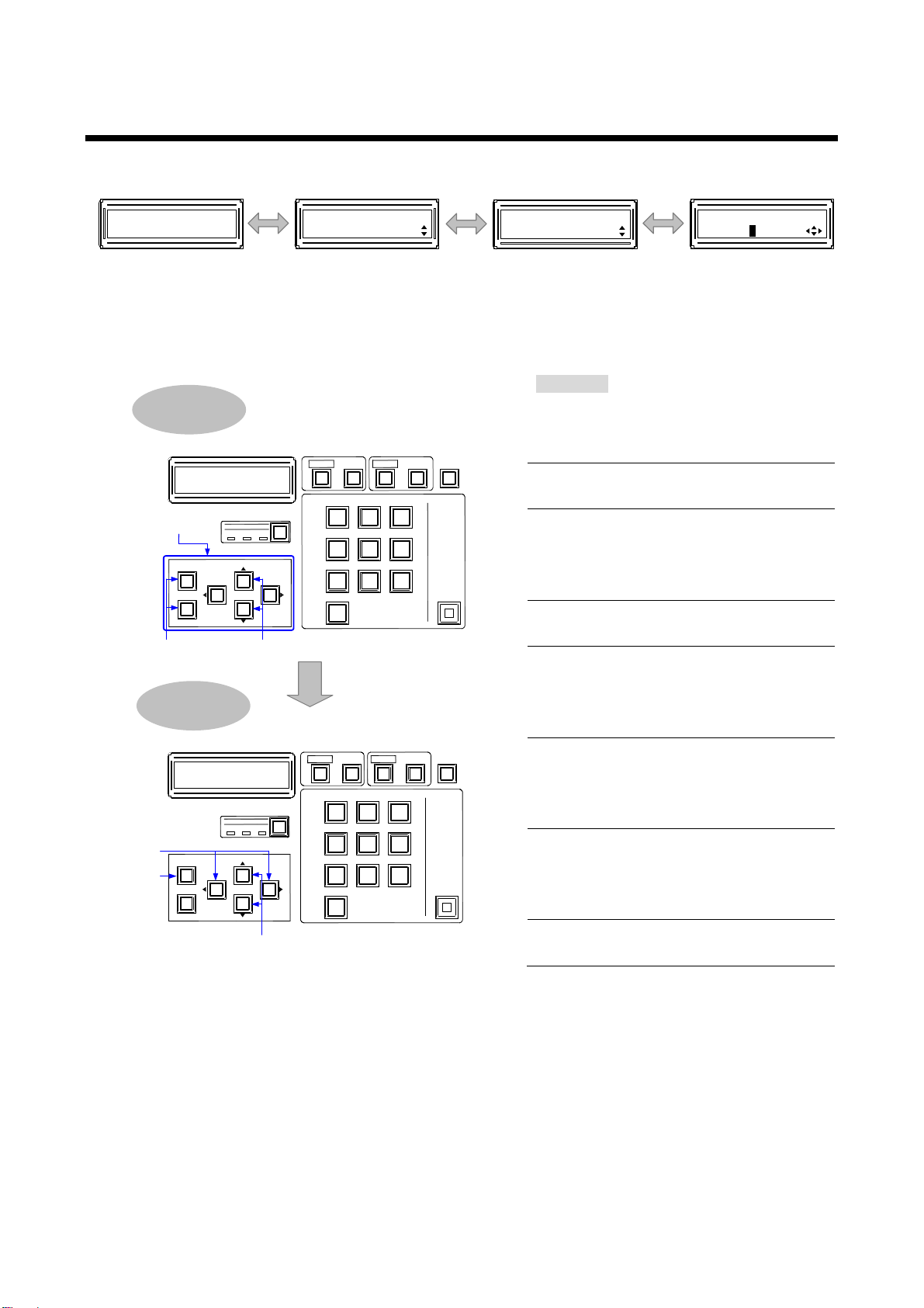
Procedure
1
Press the “MENU/SET” key to open
the main menu.*1
2
Select the desired main menu using
“▲” and “▼” keys.
3
Select the “MENU/SET” key to
move to the sub menu.
The top page can be opened again
by pressing the “ESC” key.
4
Select the desired sub menu using
“▲” and “▼” keys.
5
Select the “MENU/SET” key to
move to the setting page.
The main menu can be opened
again by pressing the “ESC” key.
6
Select the channel using “” and
“” keys.
The sub menu can be opened again
by pressing the “ESC” key.
7
Change the setting using “▲” and
“▼” keys.*2
The sub menu can be opened again
by pressing the “ESC” key
8
If the “MENU/SET” key blinks, press
the key to apply the setting.
SET
OUTPUT
ALL
INPUT
OFF
987
654
0
321
LOAD
PRESET
MENU
/SET
ESC
V&A VIDEO
AUDIO
SWITCHING MODE
SET
OUTPUT
ALL
INPUT
OFF
987
654
0
321
LOAD
PRESET
MENU
/SET
ESC
V&A VIDEO
AUDIO
SWITCHING MODE
Selecting
menu
Changing
settings
2, 41, 3, 5
7
6
8
Menu operation
keys
[FUNCTION SELECT]
INPUT SETTING
[INPUT SETTING]
INPUT EQUALIZER
[INPUT EQUALIZER]
IN1 : AUTO
2, 3 4, 5
6, 7
Main menu Sub menu Setting page
FDX-64
64x64 Matrix
1
Top page
6.2 Menu operation key
The menu consists of the top page, main menu, sub menu, and setting page.
The screen backlight is turned off if no operation is performed for 10 seconds (power saving function).
【See 7.10.3 Power saving [POWER SAVE]】
*1 Available “▲”, “▼”, “”, and “” keys are displayed at the lower right of the LCD screen and the key
LED lights.
A channel that does not have its slot board cannot be set.
*2 If the “MENU/SET” key is turned off, the set value will be applied automatically.
24
[Fig. 6.3] Menu operation
 Loading...