

IDK FDX-12UHD User Manual
4K@60 and HDCP 2.2 Digital Matrix Switcher
FDX-12UHD
<User’s Guide>
Ver.1.0.0
● Thank you for choosing our pr oduc t.
● To ensure the best performance of this product, please read this User’s Gui de fully and carefully before
using it and keep thi s manual t ogether with the product for reference as needed.
IDK Corporation

FDX-12UHD User’s Guide
Trademarks
Blu-ray Disc and Blu-ray are trademarks of Blu-r ay Disc Associ ati on.
ETHERNET is a registered t r adem ar k of Fuji Xerox Co., Ltd.
Google Chrome is a regi ster ed trademark or trademark of Google Inc.
The terms HDMI and HDMI High-Defi nition Multimedia Interfac e, and t he HDMI Logo ar e trademarks or
registered tradem ar k s of HDM I Licensi ng A dm inistrator, Inc. in the United States and other countries.
HDBaseT™ and the HDBaseT Alli anc e Logo ar e trademarks of the HDBaseT Alliance.
Javascript
companies in t he United States and other countries.
Microsoft, Windows, Internet Ex plor er ar e either registered trademarks or tradem ar k s of the Mic r osoft
Corporation in the United States and other countries.
Oracle and Java are trademar k s of Orac le Corporation its subsidiaries, and affiliated companies in the
United States and other c ountries.
The terms Anti-snow and Connection Reset are registered trademarks of I DK Corporation in Japan.
All other company and pr oduc t names mentioned in this manual are either registered trademarks or
trademark s of their r espect ive owners. In this manual, the “®” or “™” marks may not be specified.
2
®
is a trademark or registered tradem ar k of Oracl e Cor por ation, its subsidiaries, and aff iliated

FDX-12UHD User’s Guide
Before reading this manual
All rights reserv ed.
Some of the contents i n this User’s G uide such as appearance diagrams, menu operations,
communication commands, and so on may differ depending on the ver si on of the pr oduc t.
This User’s Guide is subject to change without notice. You can download the latest v er si on from IDK’s
website at: http://www.idkav.com
The reference manual consi sts of the following two volumes:
■ User’s guide (this document):
Provides explanations and procedures for operations, installation, connec tions among devices, I/O
adjustment and settings.
■ Command guide: Please download the command guide from the website above.
Provides explanations and procedures for external control using RS-232C and LAN communications.
FCC STATEMENT
This equipment has been tested and found to comply with the limits for a Class A digit al dev ic e, pursuant to
part 15 of the FCC Rules. These limit s are designed to provide reasonable protection against harmful
interfer enc e when the equipment is operated in a commercial environm ent. This equipment generates, uses,
and can radiate radio fr equenc y ener gy and, if not installed and used in accordance with the instruction
manual, may cause harmful interference to radio communications. Operation of this equipment in a residential
area is likely to cause harmful interference, in which case the user will be required to correct the interference
at his own expense.
CE MARKING
This equipment complies with the essential requir em ents of t he r elev ant European health, safety and
environmental protection legislation.
WEEE MARKING
Waste Electri c al and El ec tronic Equipment (WEEE), Directive 2002/96/ EC
(This directive is only valid in the EU.)
This equipment complies with the WEEE Directive (2002/96/EC) marking requirement.
The left marking indicates that you must not discard this electrical/elect r onic equipment in
domestic household waste.
If a 4K HDBaseT slot board is mounted, please use STP cables in order to reduce noise caused by cabl es.
3
FDX-12UHD User’s Guide
Enforcement Symbol
Description
Indicates the pr esence of a haz ar d that m ay result in death or serious
Indicates the pr esence of a haz ar d that m ay cause mi nor personal
Symbol
Description
Example
disassemble
Caution
Warning
Safety Instructions
Read and understand all safety and operating instructions before using this product. Foll ow all instr uc tions
and cautions as detailed in this document.
Caution
Prohibited
Instruction
personal injur y if the warning is ignored or the product is handled
incorrectly.
This symbol is intended to alert the user. (Warning and caution)
This symbol is intended to pr ohibit the user from specified actions.
This symbol is intended to instr uc t the user.
injury or property damage if the caution is ignored or the product is
handled incorr ec tly.
Electrical
Hazard
Do not
Unplug
4
Do not place the product in any unstabl e place.
Install the product in a horizontal and stabl e place. Oth erwise, it m ay f all/turn over and lead t o inj ur y.
Do not place the product in any environment with vibration.
Otherwise, it may mo ve/fall and l ead to injury.
Keep out any foreign objects.
from the vent holes.
For power cable/ plug :
contact your IDK representative.
disassemble
Do not repair, modify or disassemble.
touch
In the event of electrical storms, keep away from the main unit and cables su ch as
For insta lla t i on:
IDK. Improper installation may lead to the risk of fire, electric shock, injury, or property damage.
Set the power plug in a convenient pla c e to unplug e a s ily .
situation or for eas y dis connect i on during exten ded periods of n on-use.
Insert the power plug into an appropriate outlet completely.
or fire. Do not use a dam ag ed plug or conn ect to a damaged outlet.
Clean the power plug regul arly.
If the plug is covered in dust, it may increas e the r isk of firer.
Unplug immediately if the product smokes, makes unusual noise, o r produces a
the product stops smoking, contact your IDK representative.
Unplug immediately if the product falls and/or if the cabinet is damaged.
maintenance and repair, contact your IDK representative.
Unplug immediately if water or other objects are directed inside.
maintenance and repair, contact your IDK representative.
For connection
Differences in gr ound potential amon g pr oduct popul ation of inter connected produc t s and ot h er external devices
Power may be restored after all signal/control cables are connected to each device.
Warning
Prohibited
FDX-12UHD User’s Guide
In order to av oi d fire or electric s h ock , d o not all ow foreign objects, su c h as m etal and paper, t o ent er the product
• Do not scratch, heat, or modify, including lengthening them.
• Do not pull, place heavy objects on them, or pinch them.
• Do not bend, twist, or tie them together forcefully.
Misuse of th e pow er c able and plug may cause fire or electric shock. If power cables/plugs become damaged,
Do not
Do not
Instruction
Unplug
Since the product includes circuitry that uses potentially lethal, high voltage levels, disassembly by unauthorized
personnel may lead to the risk of fire or electric shock. For internal inspection or repair, contact your IDK
representative.
power cable and LAN cable.
Contact may cause electric shock
The product is intended to be installed by skilled technicians. For installation, please contact a system integrator or
Unobstr uc t ed ac cess to the pl ug en ab les unplug gi ng t h e product in case of an y ext raordinary failur e, abnormal
If the plug is partially inserte d, arching may cause the connection to overheat, increasing the risk of electri cal shock
burning odor.
If you continue to use the product under these conditions, it may cause electr ic shock or fi re. After confirming tha t
If you continue to use the product under these conditions, it may increase the risk of electrical shock or fire. For
If you continue to use the product under these conditions, it may increase the risk of electrical shock or fire. For
may increase the risk of electric shock to personnel or cause damage to the devices or cabling infrastructure. When
using cables to connect devices, including connection of long-distance transmission cables, unpl ug the power
Instruction
cables of all interconnected devices.
5

FDX-12UHD User’s Guide
●Unplug immediately if the product smokes, makes unusual noise, or produces a
●
●
maintenance and repair, contact your IDK representative.
Warning
■ If the following problem occurs:
burning odor.
If you continue to use the product under these conditions, it may cause electr ic shock or fire.
Unplug
Unplug immediately if the product is damaged due to falling .
If you continue to use the product under these conditions, it may increase the risk of electrical shock or fire. For
maintenance and repair, contact your IDK representative.
Unplug immedia tely if water or ot he r ob je c t s are directed inside.
If you continue to use the product under these conditions, it may increase the risk of electrical shock or fire. For
6
●Do not place the product in any place where it will be subjected to high
●
●
●
●
Exceed in g the rating of an outl et m ay inc r ease the risk of fire and elec t ric sh ock .
No wet hands
●Do not plug or unplug with wet hands.
●Use and store the product within the specified temperature/humidity range.
●
●
●
on the b ott om
Reinstall the originally supplied rubber feet u s ing only the originally supplied screws.
Prohibited
●Use only the supplied power cable and AC adapter.
●
●If the pro duc t won’t be used for an extended period of time, unplug it.
●
To prevent electric shock.
Hazard
●Double Pole / Neutral Fusing
Caution
■ For installing an d c onnecti ng pr o duc t s :
FDX-12UHD User’s Guide
temperatures.
If the product is subjected to direct sunlight or high temperatures while under operation, it may affect the
product’s performance and reliability and may increase the risk of fire.
Do not place the product in dusty, oil smoke filled, or humid place.
Prohibited
If the product is placed near humidifiers or i n a dusty area, it may increase the risk of fire or electric s hoc k .
Do not block the vent holes.
If ventilation slots are blocked, it may cause the prod uc t to ov erheat, affecting performance and reliability and
may increase the risk of fire.
Do not place or stack heavy items on the product.
Failure to observe this precaution may result in damage to the product and other property and may lead to the
risk of pers on al in jury.
Do not exceed ratings of outlet and wiring devices.
Failure to observe this precaution may incr ease the risk of electrical shock.
If the prod uc t is used outside the specified range for temperature and humidity conti nuously, it m ay increase the
risk of fire or electric shock.
Do not place the product at elevations of 2,000 meters (1.24 mi.) or higher abo ve
sea level.
Failure to do so may shorten the life of the internal parts and result in malfunctions.
Instruction
When mounting the product into the rack, provide sufficient cooling space.
Mount th e pr oduc t in a the rack meeti ng EIA standards , an d m aint ain spac es ab ov e and b el ow for air circulati on.
For your safety, att ac h an L-shaped bracket in addition to the panel mount bracket kit to improve mechanical
stability.
Never insert screws without the rubber feet into the threaded holes
of the prod uc t.
Never insert screws without the rubber feet into the threaded holes on the bottom of the product. Doing so may
lead to damage when the screws contact electrical circuitry or components inside the product.
■ For operating pr od uc t s :
Do not use the supplied power cable and AC adapter with other products.
If non-compliant adapter or power cables are us ed, it m ay increase the risk of fire or electrical shock.
Failure t o observe this precaution may incr ease the risk of fire.
Unplug
Unplug the product before cleaning.
■ For power
Electrical
If a fus e blows ou t, it m ay c ause electric s h ock .
7

FDX-12UHD User’s Guide
Table of Contents
1 Included items .....................................................................................................................................10
2 Product outline ....................................................................................................................................11
3 Feature ...............................................................................................................................................12
4 Panels .................................................................................................................................................13
4.1 Front panel...................................................................................................................................13
4.2 Rear panel ...................................................................................................................................14
5 System Configur ation Example ............................................................................................................15
6 Precautions .........................................................................................................................................16
6.1 Installation....................................................................................................................................16
6.2 Cabling ........................................................................................................................................17
6.2.1 Cables ..................................................................................................................................18
6.2.2 Twisted pair cable for extension ............................................................................................19
6.2.3 Connecting RS-232C cable ...................................................................................................20
6.2.4 Alarm ....................................................................................................................................20
6.2.5 Connecting MAU-1616 ..........................................................................................................20
7 Basic Operation ...................................................................................................................................21
7.1 Channel switching mode ..............................................................................................................21
7.2 Selecting I/O channel ...................................................................................................................22
7.2.1 Selecting I/O channel in INPUT→OUTPUT mode .................................................................23
7.2.2 Selecting I/O channels in OUTPUT→INPUT mode................................................................24
7.3 Menu operation key s ....................................................................................................................25
7.4 Recalling preset memory ..............................................................................................................26
7.5 Key function lock ..........................................................................................................................27
7.6 Initialization ..................................................................................................................................28
7.7 Control from WEB browser ...........................................................................................................32
7.7.1 How to use WEB menu .........................................................................................................33
7.7.2 Operations only settable from WEB menu .............................................................................34
8 Menu ...................................................................................................................................................38
8.1 Menu list ......................................................................................................................................38
8.2 Input setti ng .................................................................................................................................39
8.2.1 No-signal input monitoring time .............................................................................................39
8.2.2 Input HDCP setting ...............................................................................................................40
8.3 Output setting...............................................................................................................................41
8.3.1 Output mode .........................................................................................................................41
8.3.2 Output mode for EDID error ..................................................................................................42
8.3.3 Hot plug ignori ng dur ation .....................................................................................................42
8.4 Audio ...........................................................................................................................................43
8.4.1 Digital audio output ...............................................................................................................43
8.5 EDID ............................................................................................................................................44
8.5.1 EDID resolution ....................................................................................................................45
8.5.2 Copying EDID .......................................................................................................................48
8.5.3 Loading EDID channel ..........................................................................................................48
8.5.4 Deep Color input ...................................................................................................................49
8.5.5 Audio channel .......................................................................................................................50
8.5.6 Linear PCM Audio.................................................................................................................51
8.5.7 AC-3 Dolby Digital Audio.......................................................................................................51
8.5.8 AAC Audio ............................................................................................................................52
8

FDX-12UHD User’s Guide
8.5.9
Dolby Digital Plus Audio ........................................................................................................52
8.5.10 DTS Audio ............................................................................................................................53
8.5.11 DTS-HD Audio ......................................................................................................................53
8.5.12 Dolby TrueHD Audio .............................................................................................................54
8.5.13 WXGA ..................................................................................................................................54
8.6 RS-232C settings .........................................................................................................................55
8.6.1 RS-232C ..............................................................................................................................55
8.7 LAN settings ................................................................................................................................56
8.7.1 IP address ............................................................................................................................56
8.7.2 Subnet mask ........................................................................................................................56
8.7.3 TCP port ...............................................................................................................................57
8.7.4 Viewing MAC address...........................................................................................................58
8.8 Preset memory .............................................................................................................................58
8.8.1 Recalling cr oss point .............................................................................................................58
8.8.2 Saving cross point ................................................................................................................59
8.8.3 Editing cross point ................................................................................................................60
8.8.4 Start-up status ......................................................................................................................61
8.9 Other settings...............................................................................................................................62
8.9.1 Grouping keys for key function lock .......................................................................................62
8.9.2 Operation sound ...................................................................................................................62
8.9.3 Power saving ........................................................................................................................63
8.9.4 Alarm ....................................................................................................................................64
8.9.5 Top page ..............................................................................................................................65
8.9.6 Viewing input signal status ....................................................................................................67
8.9.7 Viewing sink device status ....................................................................................................67
8.9.8 Viewing slot board status ......................................................................................................68
8.9.9 Viewing cooling fan status.....................................................................................................69
8.9.10 V iewing power-supply voltage ...............................................................................................70
8.9.11 V iewing system status ..........................................................................................................71
8.9.12 Viewing firmware and hardware versions ..............................................................................72
9 Product specifi c ation ...........................................................................................................................73
10 Troubleshooting...................................................................................................................................75
9
FDX-12UHD User’s Guide
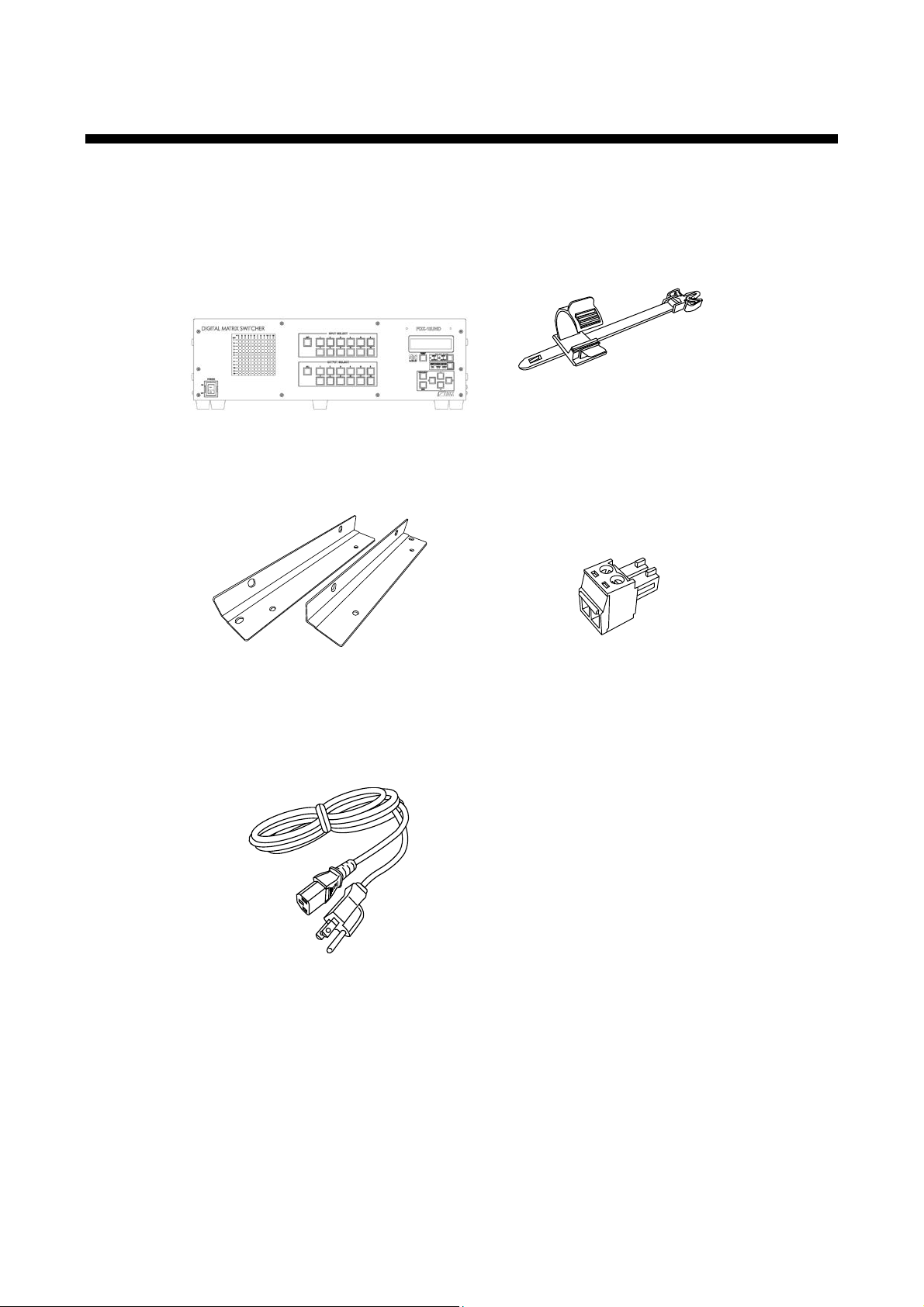
One (1) FDX-12UHD main unit
One (1) power cord 5.9 ft. (1.8 m)
1 Included it e ms
Make sure all items below are i ncl uded in the package.
If any items are missing or damaged, please contact IDK.
Two (2) rack mounting brac k ets
Cable clamps*
*Depends on the number of slot boards
One (1) 2-pin terminal bloc k
[Fig. 1.1] Inc luded ite m s
10
FDX-12UHD User’s Guide
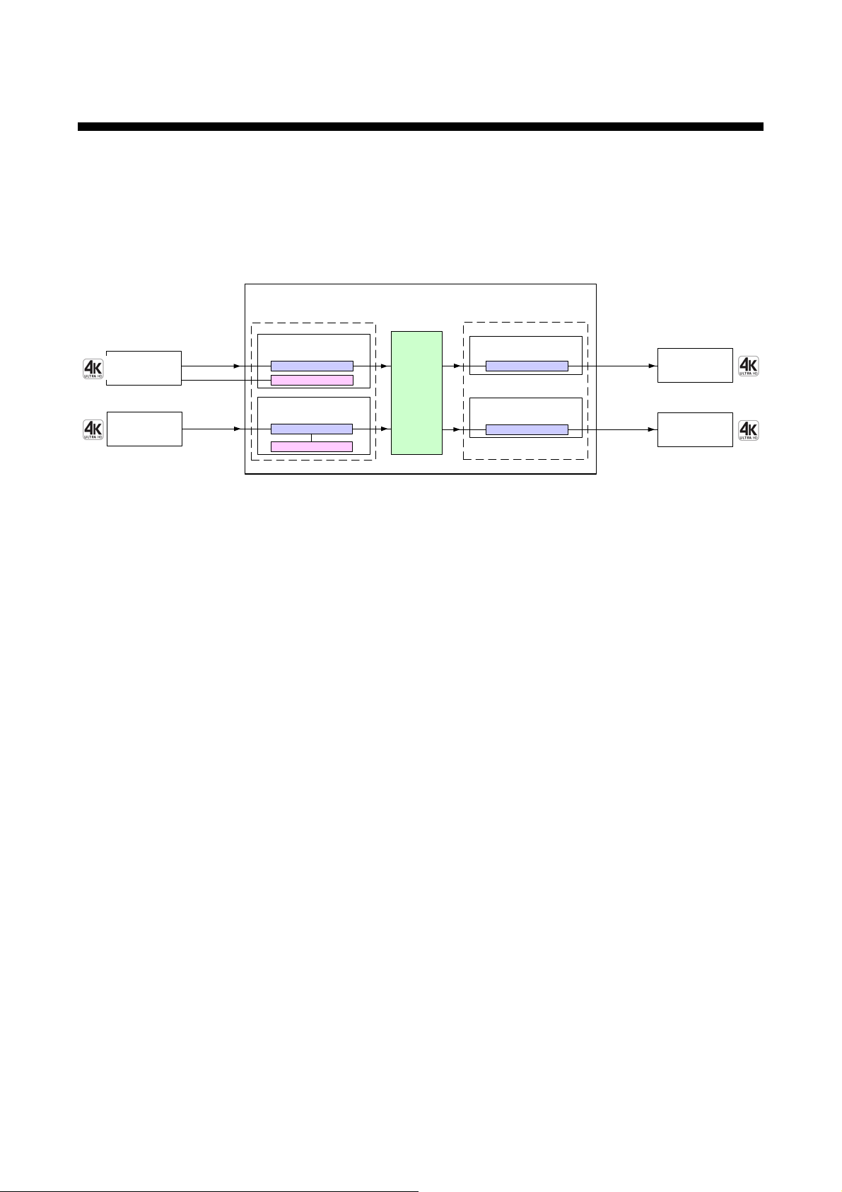
FDX-12UHD
inputs/1 slot board
4
4K HDBaseT input slot board
outputs/1 slot board
4K HDBaseT output slot board
4
Digital video/audio/
communication for
extension
HDBaseT
Digital video/audio/
communication for
extension
HDBaseT
Receiver
EDID emulator
Transmitter
Up to outputs/3 slot boards
12
Up to inputs/3 slot boards
12
Video/audio
matrix
switch
12IN-12OUT
・ Input slot board: Can be added by 4 inputs
・ Output slot board: Can be added by 4 outputs
inputs/1 slot board
4
4K digital input slot board
Digital video/audio
HDMI DVI
EDID emulator
outputs/1 slot board
4K digital input slot board
4
Digital video/audio
HDMI DVI
Up to 98 ft.
(30 m)*
Up to 328 ft.
(100 m)
Up to 98 ft.
(30 m)*
Up to 328 ft.
(100 m)
Receiver
Transmitter
*Maximum extension distance
1080p@60: 98 ft. (30 m)
4K@60: 39 ft. (12 m) (when 18 Gbps high-speed cable is used)
2 Product outline
The FDX-12UHD (hereafter referred to as “FDX”) is a digital matrix switcher hav ing 12 inputs / 12 outputs,
supporting up to 4K@60 and HDCP2.2.
Since the FDX supports combinations of digital slot boards and HDBaseT slot boar ds, t he system can be
simplified.
The FDX has RS-232C and LAN for an external control communic ation port. Digital video and analog audio
can be switched separatel y usi ng M A U-1616 (optional audio matrix switcher).
4K digital input slot board
4K HDBaseT input slot board
4K digital output slot board
4K HDBaseT output slot board
Note:
I/O slot boards for the F DX cannot be used for other product s and vice versa.
[Fig. 2.1] I/O diagram
One 4K digital input slot board includes four HDMI connectors.
DVI signals can be input to HDMI c onnec tors (conversion cable is necessary).
One 4K HDBaseT input sl ot board includes four RJ-45 connectors.
Digital signals (Audio/Video) can be transmitted up to 328 ft. (100 m) by using with HDC-T serie s
products.
One 4K digital output sl ot board inc ludes four HDMI connectors.
The HDMI connector outputs video and audio of the selected i nput channel.
One HDBaseT output sl ot board includes four RJ-45 connectors.
The RJ-45 connect or outputs video and audio of the selected input channel.
Digital signal s (Audio/Video) can be transmitt ed up to 328 ft. (100 m ) by using with HDC-R series
products.
11
FDX-12UHD User’s Guide
■
■
■
3 Feature
Video
・ Up to 4K@60 (4:4:4)*
・ HDCP 1.4 / 2.2
・ Maximum extension di stanc e (4K digital input / output slot boar d)
1080p@60: 98 ft. (30 m)
4K@60: 39 ft. (12 m) (when 18 Gbps high-speed cable is used)
・ Up to 328 ft. (100 m) over a Cat6 cable
・ Anti-Snow
・ HDR
・ 3D
・ x.v.Color
・ The number of I/Os is customizable by 4 inputs or 4 outputs
* 4K HDBaseT I/O slot board: Up to 4K@60 (4:2:0)
[Fig. 3.1] Combination example of slot boar ds
Control input
・ RS-232C, LAN
Others
・ EDID emulation
・ Audio breakaway enables independent audio and video switching (Audio unit MAU-1616 is
required (Optional)
・ I/O slot board, CPU slot board, and f an unit can be replac ed without taking off the unit from rac k
mount
・ Instant Alert output (Power unit monitoring, Fan unit monitoring, Temperature monitoring)
・ Startup memory
・ Preset memory
・ Last m emory
・ Connection Reset
・ Security lock
・ Viewing system status
・ All function settings thr ough br owser
・ Redundant power supply unit (optional)
・ RS-232C transmission (4K HDBaseT input / output slot board)
12
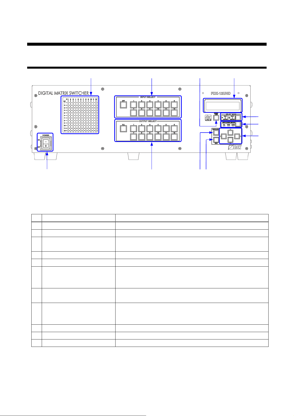
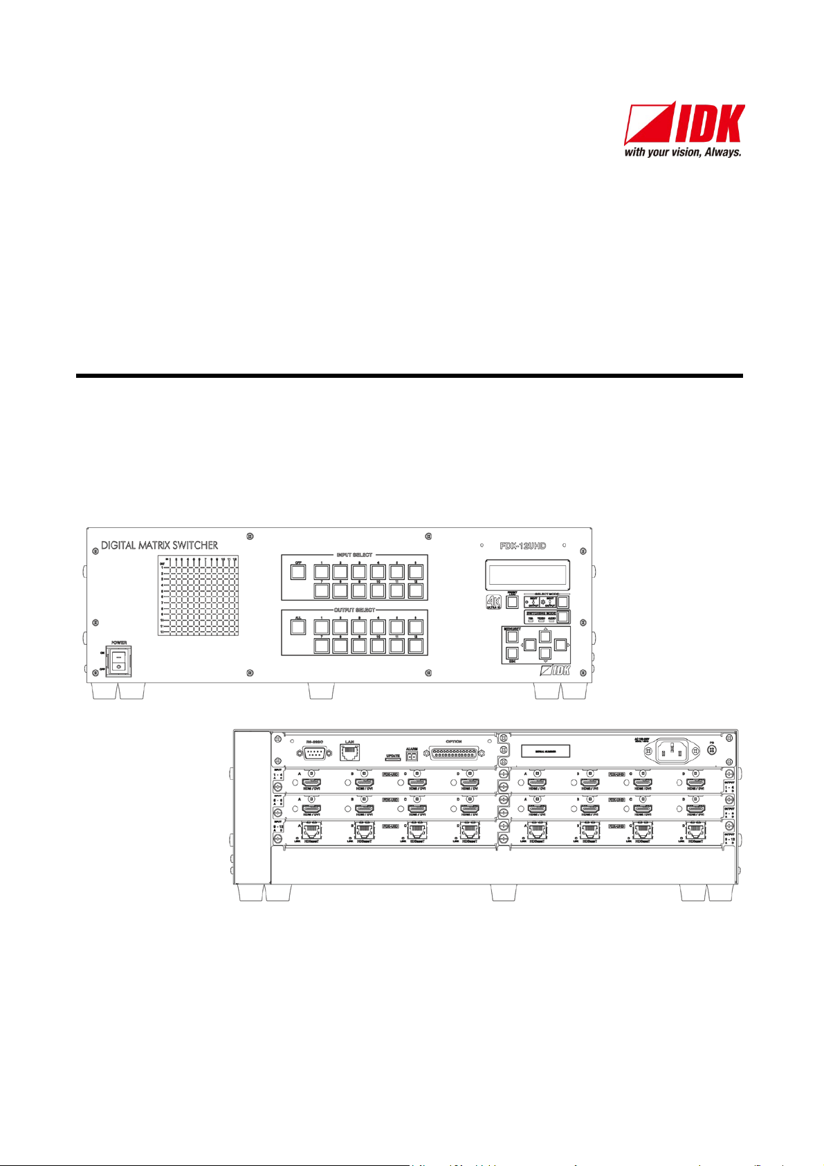
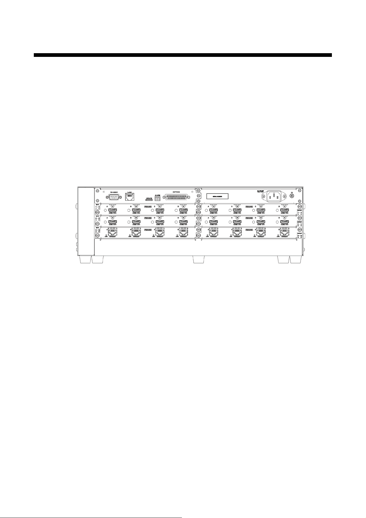
4 Panels
⑩
⑤
①
⑪
⑨
⑥
⑦
⑧
④
③
②
#
Feature
Description
POWER switch
Powers ON / OFF the FDX.
LCD screen
Displays menus and settings.
MENU/SET key
Selects menus and edit s / contr ols / saves settings.
4.1 Fro nt pa ne l
FDX-12UHD User’s Guide
[Fig. 4.1] Front panel drawing
[Table 4.1] Front panel features
①
②
③
Applies the setti ng.
ESC key Ends the current menu setti ng.
④
Arrow keys (▲, ▼, ◄, ►) Switch menu, mov es cursor, and c hanges setting values.
⑤
SWITCHING MODE key Selects a switching mode V&A (FDX and MAU-1616), VIDEO
⑥
(only FDX),
AUDIO (only MAU-1616) for when I/O channel is switched.
Switching direc tion
⑦
selection key
Input channel sel ec tion keys Selects the input channel.
⑧
Output channel selection keys Selects output channels.
⑨
PRESET LOAD key Moves to the menu for recalli ng pr eset m em or y.
⑩
I/O channel stat us di spl ay Display selected I/O channels.
⑪
Selects a switchi ng dir ec tion (INPUT→OUTPUT or
OUTPUT→INPUT) when channels are being set.
Selects a preset memor y number when ⑩(PRESET LOAD key) is
enabled.
13
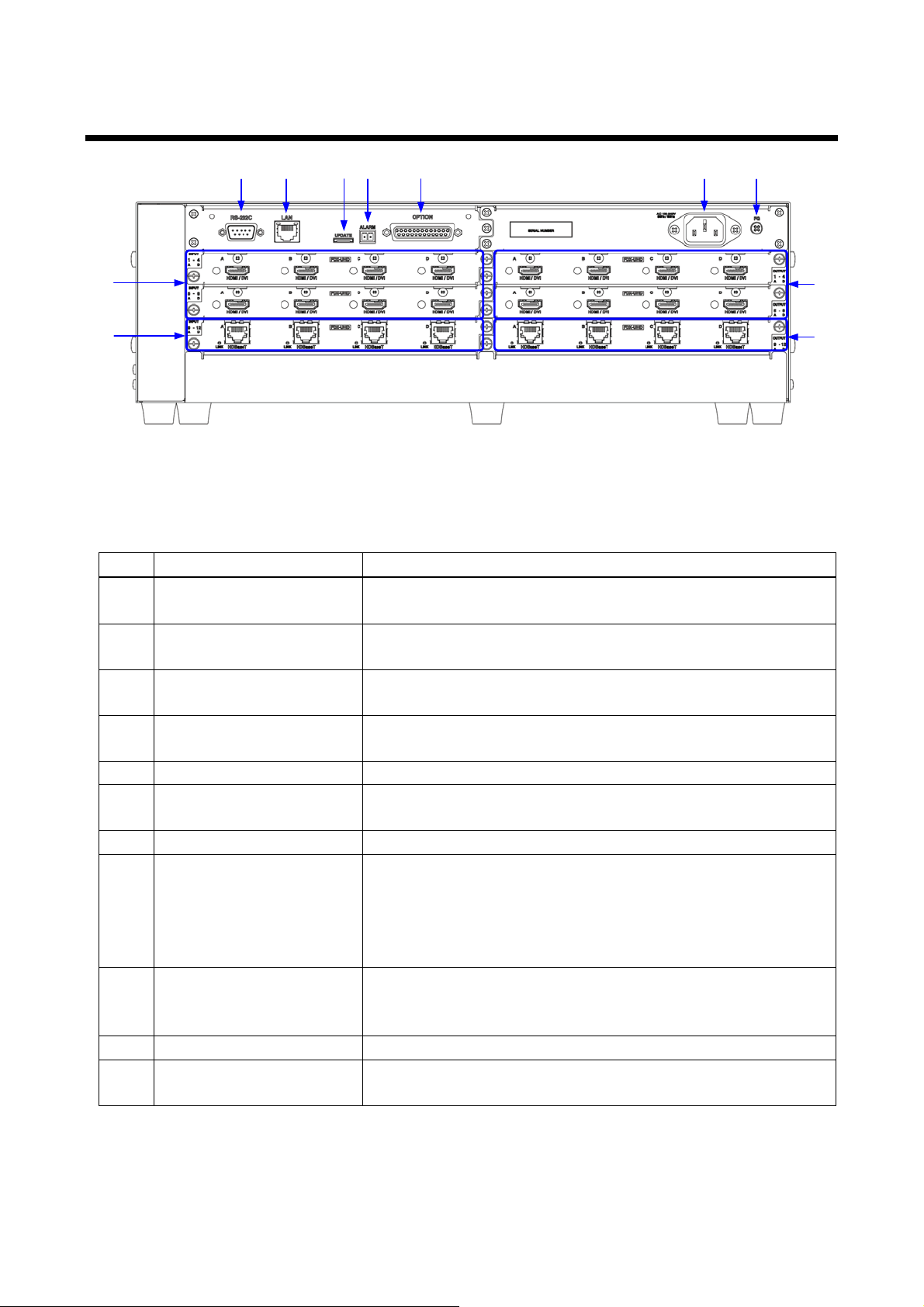
FDX-12UHD User’s Guide
⑥
①
②
③
④
⑤
⑦ ⑧ ⑨
⑩
⑪
devices, such as Blu-ray® players.
HDBaseT input connec tor
Digital signal s (Audio/Video) can be transmitt ed up to 328 ft. (100
m) by using with HDC-T series product s.
HDMI output connect or
Output connector for HDMI and DVI signal interfaces with sink
m) by using with HDC-R series products.
RS-232C connector
For external control by c ommunication commands.
LAN connector
For external control by c ommunication commands or web
】
】
See: 8.9.4 Alarm】
OPTION connector
Connector for MAU-1616 (optional).
When no MAU-1616 is used, do not connect any cable.
AC power inlet
For using with provided power cable.
4.2 Rear panel
[Fig. 4.2] Rear panel drawing
[Table 4.2] Rear panel features
# Feature Description
① HDMI input connector Input connector s for HDMI and DVI si gnals to interface source
②
③
devices such as LC monit or s and projectors.
④ HDBaseT output connector Digital signal s (Audio/Video) can be transmitt ed up to 328 ft. (100
⑤
⑥
browsers.
⑦ Mai ntenance connector Factory use only.
⑧ ALARM connector By using a 2-pin terminal block , problems in cooling fans, I/O slot
boards, supply voltage, and internal temper ature can be detected.
【See: 1 Included items
【See: 6.2.4 Alarm
【
⑨
Connect the provided bus cable.
⑩
⑪ Frame ground Use for bonding c hassis to local ground.
An M4 screw is used.
14
FDX-12UHD User’s Guide
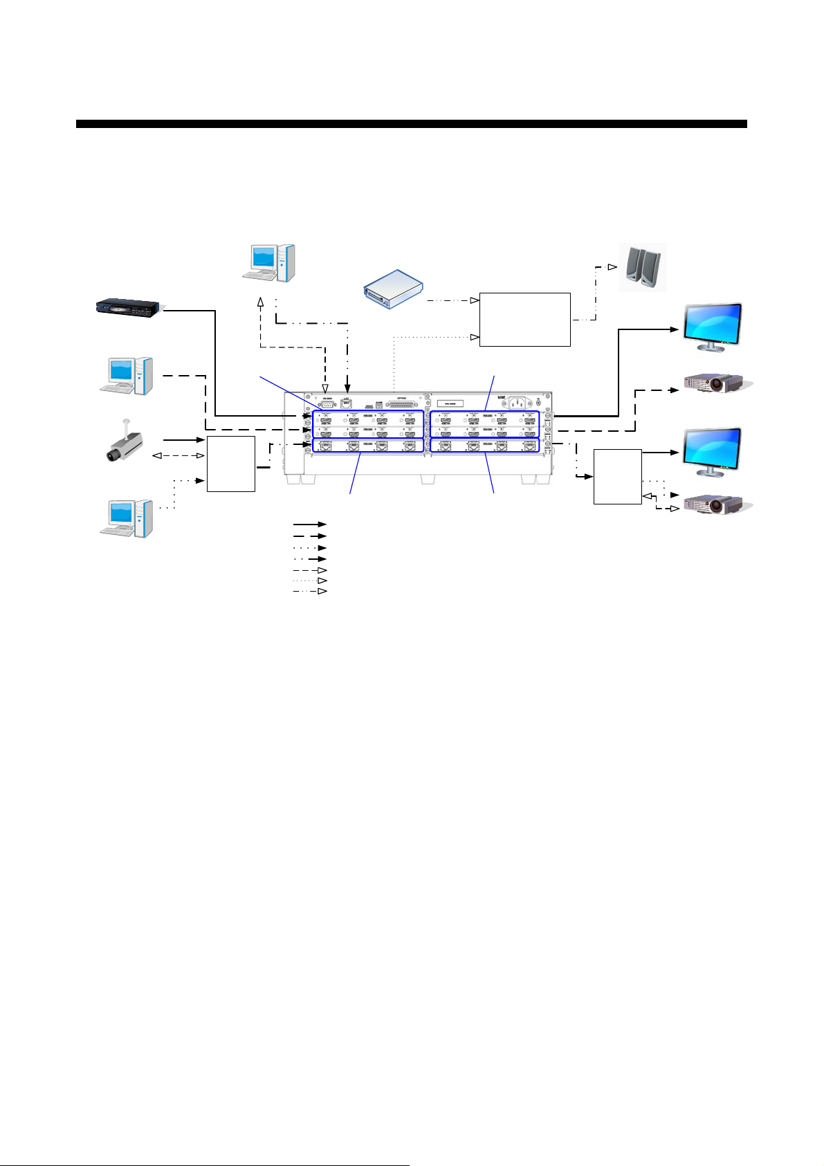
HDMI
Blu-ray player
Projector
4K monitor
PC
Digital input
connection
Camera
PC
HDB as eT input
connection
DVI
HDMI
Digital output
connection
DVI
Projector
4K monitor
HDB as eT output
connection
PC
Video/audio input
External device
Video/audio output
Speakers
Audio output
FDX-12UHD
HDMI /DVI conversion cable
DVI cable
Cat5e/Cat6 cable
RS-232C cable
Provided bus cable (D-Sub25-pin straight cable)
RCA cable
RS-232C
LAN
Analog audio
output
MAU-1616
HDC-T
Analog audio
input
Audio input
CD player
HDC-R
HDMI
HDMI
HDMI cable
RS-232C
RS-232C
HDMI /DVI
HDMI /DVI
5 System Configuration Example
RS-232C signal can be transmitted using mounted 4K HDBaseT slot board. In the figure below, the FDX
controls devi c es that are c onnec ted to HDC series products over RS-232C.
[Fig. 5.1] Configuration example
15
FDX-12UHD User’s Guide
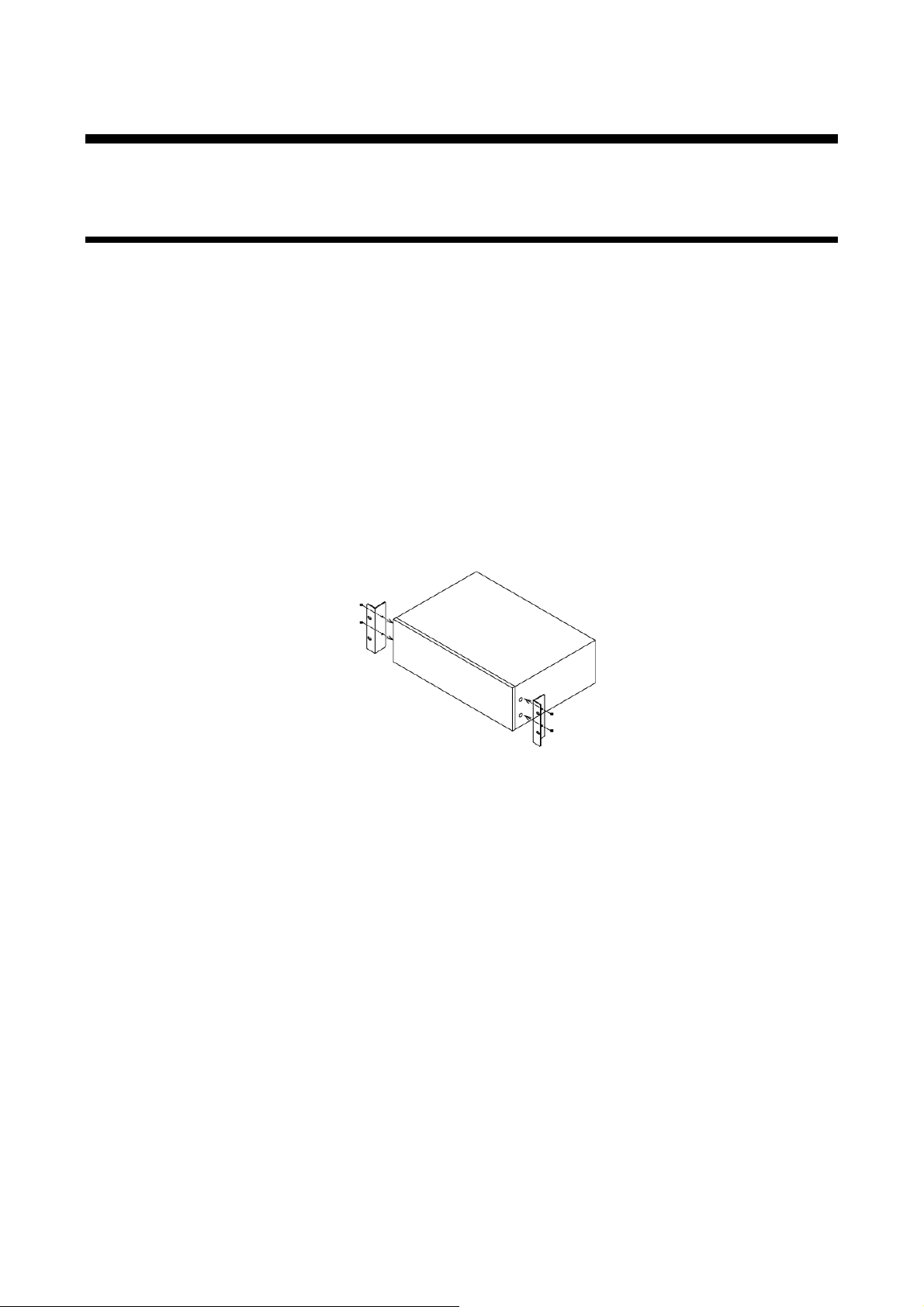
M5-screws
Unit
M5-screws
6 Precautions
Before connecting to external devices, follow the precautions below.
6.1 Installation
When installing the FDX, please observe the following precautions.
● Do not bloc k vent hol es. To provide adequate ventilation, maintain sufficient clearances around the
FDX 1.18 in. (30 mm) or more.
● When the FDX needs to be mounted in an EIA rack, or an enclosed space, ensure that suffici ent
ventilation or c ooling is provided and that the ambient temperature will not exceed 40°C / 104°F. If
inadequately vented, the product’s service life, operati on and r eliability may be affect ed.
■ Attaching rack mounting b racket s
1. Remove four M5 screws from one side of the unit. Retain t hese screws for step 2.
2. Attac h one br ac k et t o the side of t he unit using the screws removed in step 1.
3. Repeat steps 1 and 2 on the other si de of the unit.
[Fig. 6.1] Attaching rack mounting brackets
Note:
The standard screw tightening torque is 2.94 N・m (about 30 kgf・cm).
16
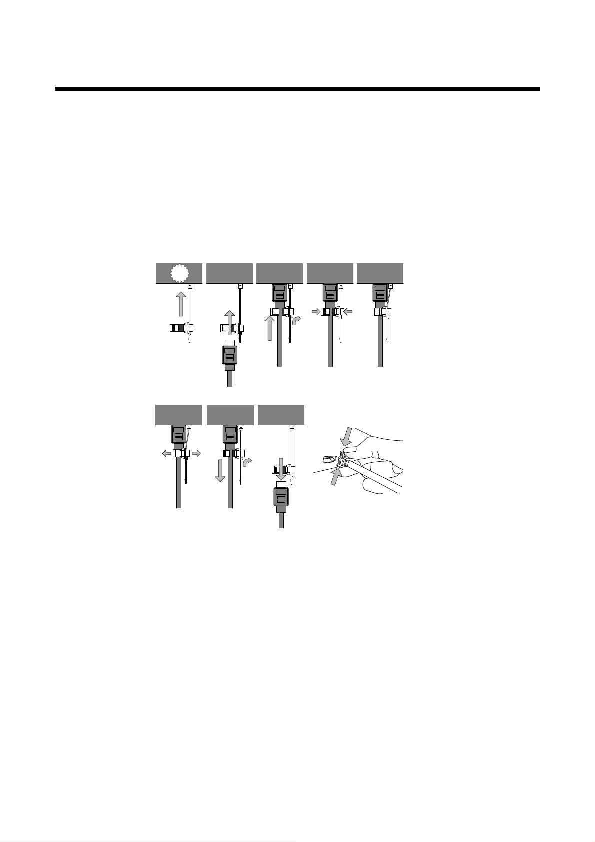
FDX-12UHD User’s Guide
Fixing HDMI cable
using cable clamp
Removing HDMI cable
and cabl e clamp
①
②
③
Pull out while pressing
④
② ④ ⑤① ③
Click
6.2 Cabling
When connecting the FDX to external devices, please observe the following precautions.
・Read manuals for the exter nal dev ices.
・ Before you connecting cables to the FDX or an external device, dissipate stat ic electricity by touching
grounded metal such as racks before handling signal cables. Failure to observe this precaution may
result in ESD (electrostatic discharge) dam age.
・Power all units off before connecting cables.
・Be sure to fully seat all plugs and connections and dress cables to reduce stres s on connectors.
・Secure HDMI cables using cable clamps to prevent connectors from being accidently pulled out of ports.
[Fig. 6.2] Attaching cable clamp
17
FDX-12UHD User’s Guide
- -
-
6.2.1 Cables
IDK has a large selecti on of fl exi ble HDMI cables, DVI cables, high-quali ty long cables, and conversion
cables.
Use the correct cable depending on the system confi gur ation.
For analog audi o and RS-232C, select or fabricate cables to match the connectors as needed.
For 4K format video, t he maximum TMDS data r ate (transmission speed) is 18 Gbps. If a high-speed HDMI
cable that supports up to 10.2 Gbps rate is used, video cannot be displ ay ed stably. Select an appropriat e 18
Gbps high-speed cable depending on the 4K format.
The maximum distance may change depending on cable type and charact eri stics of source and sink devices.
[Table 6.1] 18 Gbps high-speed cable for 4K format
TMDS data rate (Gbps)
RGB, YCbCr 4:4:4 YCbCr 4:2:2 YCbC r 4:2:0
4K format
3840x2160p (24 / 25 / 30)
4096x2160 (24 / 25 / 30)
3840x2160p (50 / 59.94 / 60)
4096x2160 (50 / 59.94 / 60)
18 Gbps: 18 Gbps high-speed cable, 10.2 Gbps: 10.2 Gbps cable, -: N/A
Notes:
・If connecting an HDC series product in order to transmit DVI signals that are protected by HDCP,
use IDK’s HDBaseT cable extender supporting DVI signals.
・If a cable is extended and a cable joint (JJ) is used, video may be interrupted or may not be output.
24 bit 30 bit 36 bit 24 bit 30 bit 36 bit 24 bit 30 bit 36 bit
10.2
Gbps
10.2
Gbps
18 G
bps
18
Gbps
18
Gbps
18
Gbps
-
-
18
Gbps
18
Gbps
-
10.2
Gbps
10.2
Gbps
18
Gbps
18
Gbps
10.2
Gbps
10.2
Gbps
18
Gbps
18
Gbps
10.2
Gbps
10.2
Gbps
18
Gbps
18
Gbps
- - -
-
10.2
Gbps
10.2
Gbps
18
Gbps
18
Gbps
18
Gbps
18
Gbps
18

FDX-12UHD User’s Guide
Noise
Type
Extension
TMDS clock
Recommended cable
Easily
UTP
Cat5e
164 ft.
(50 m)
225 MHz
164 ft. (50 m) or longer:
Cat6
328 ft.
(100 m)
230 ft.
(70 m)
> 225 MHz
4K 230 ft. (70 m) or longer:
Less
affected
STP
Cat5e*
Cat6
328 ft.
(100 m)
6.2.2 Twisted pair cable for extension
To ensure the best perf ormance of twisted pair cables, select a cor r ect twisted pair cable and connect it
correctly.
● Cat5e UTP/STP and Cat6 UTP/STP can be used, but we recommend CAT.5E HDC cable* for optimal
performance.
● If using an STP c able, connect t he FG connector to a ground source. Ot herwise, t he shiel ding feat ure
does not work correctly . W hen usi ng a UTP c able, we still recommend using the ground connect or .
● The shiel ded STP c ables are less affected by interference or ext er nal noise than UTP cables.
● Connectors for long-haul extension are t he same as that of eight-core modular connector used for
Ethernet, but t he transmission system is not the same so that it cannot be connec ted to Ethernet.
● The maximum ext ensi on distance of a twisted pair cables is the shorter distance of the maximum
extension distances of transmitter/rec eiv er /sink device connected to the FDX.
● Pin assignments: T568A or T568B straight
● Do not pull the cable hard. The allowable tension of the t wisted pair cable is 110 N.
● Do not bend the connec tion cable at a sharp angle. Keep the bend radius four times of the cable diameter
or larger.
● Do not tie the cable tightly; leave a space allowing t he cabl e to move slightly.
● If you use multiple twisted pair cables, we recommended keeping a distance between the cables or not
to place the cables closel y in par allel.
● Keep the twisted pair cable as straight as you can. If you coil the cable, it is easily affected by noise.
● Do not place the cable in an electrically noisy environment, since high-speed signals are transmitted.
Particularl y when you use a high-out put radio around the FDX, video or audio may be interrupted.
● If t he total extension distance f rom the transmi tter to receiver i s 328 ft. (100 m) or l ess, up to two cable
joints can be used. Product s supporting Cat6A (10GBase-T) are recommended.
● The table below shows supported extension distance for each twisted pair cable categor y. Note that the
distance may shorten depending on the actual environment.
[Table 6.2] Twisted pair cabl e extensio n dist ance
≦
affected
(4K format)
* The CAT.5E HDC cable is a doubl e-shi elded twisted pair cable that optimizes video signal transmission of
IDK’s HDC series product (twisted pair cable extenders and spli tt er s), M S D and FDX series product s
(products with extending function).
The CAT.5E HDC cable is certif ied to 500 MHz bandwidth at distance up t o 330 feet (100 m) and verified to
meet requirements specified by HDBaseT Alliance. The double-shielded structure protects video signal from
outside interference. In order to maximize the performance of the CAT.5E HDC cable, use IDK’s transmitters
and receivers with STP’s R J-45 connector and keep the cabl e gr ounded.
Note:
If there is a problem in the t r ansmission path, video and audio may be interrupt ed. Please check the items
above. If the problem still cannot be solved, shorten the length of the twisted pair cable.
Cat5e STP, Cat6 UTP / STP,
CAT.5E HDC*
Cat5e STP, Cat6 STP,
CAT.5E HDC*
19
FDX-12UHD User’s Guide
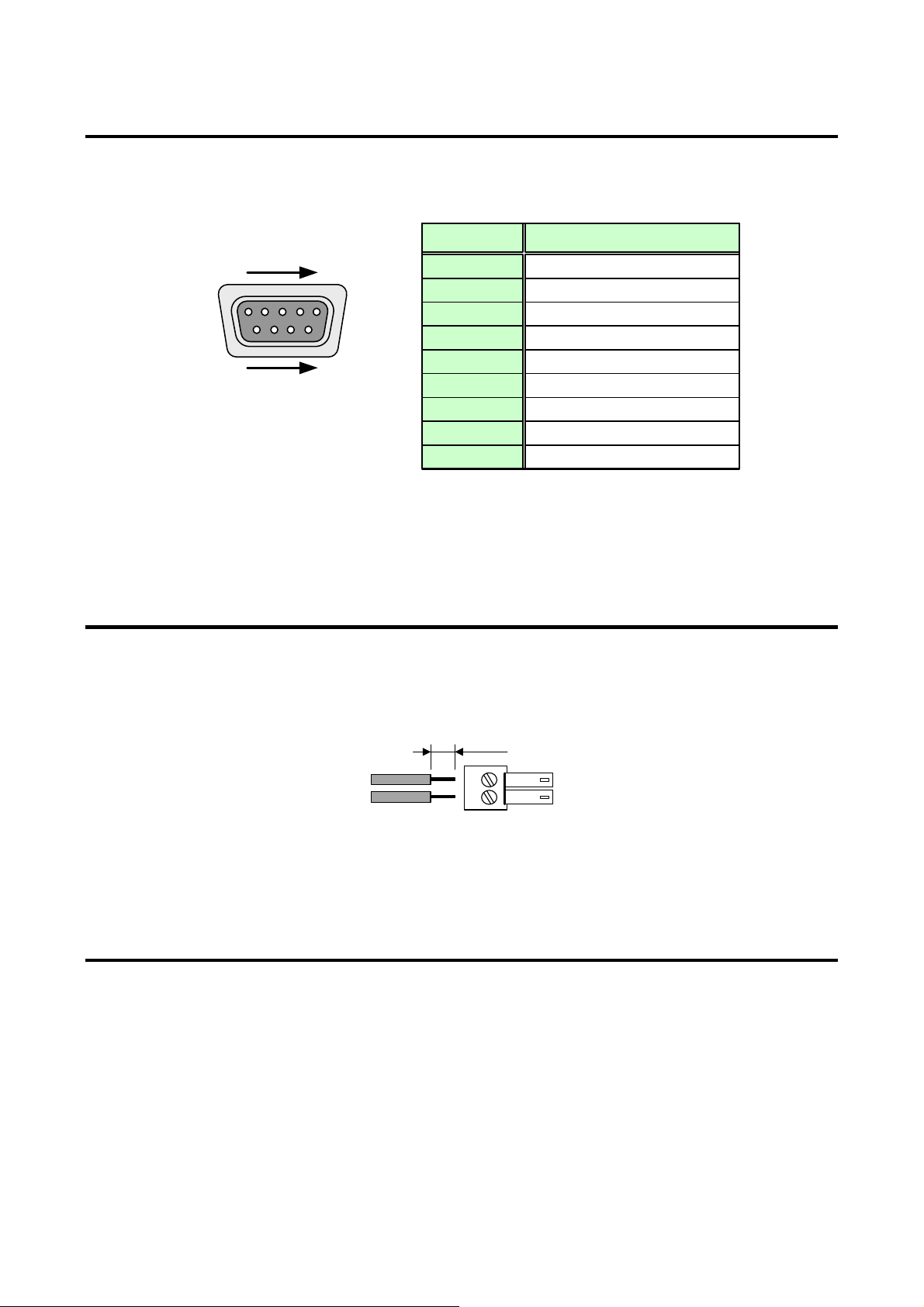
D-sub 9-pin, male
1
5
RS-232C connector
6
9
RxD
TxD
N.C.
DTR
DSR
N.C.
GND
RTS
CTS
Pin #
1
3
2
4
6
5
7
9
8
Signal
(Receiving data)
(Sendi ng data )
(Ground)
(Sendi ng request )
(Receiving request)
(Not used)
(Not used)
(Not used)
(Not used)
U p to 0.28" (7 mm)
6.2.3 Connecting RS-232C cable
For RS-232C ports, 9-pin D -sub male pin is used.
Use a cross cable t o c onnec t t he FDX to PC.
[Fig. 6.3] 9-pin D-sub connector, male
6.2.4 Alarm
Connect the provided 2-pin terminal block to the ALARM connector in or der to det ect pr oblems in the cooling
fan, I/O slot boards, power supply voltage, and inter nal temper ature.
AWG28 t o AWG16 conductor gauge is recomm ended. The recommended wire strip length is 0.28 in. (7 mm).
[Fig. 6.4] Connecting 2-pi n Te r m inal block
6.2.5 Connecting MAU-1616
Connect the bus cable t hat is provided with the MAU-1616 to the OPTION connector in or der to use the
MAU-1616, a matrix switcher that switches audi o sep ar ately.
See “MAU Series (MAU-1616 / MAU-3232) User’s Guide” for details of the MAU-1616.
20
FDX-12UHD User’s Guide
7 Basic Operation
This User’s Guide explains operat ions from the front panel of the FDX and a Web browser. See FDX-12UHD
Command Guide for control by c ommands.
If “8.9.3 Power saving” is set to “ON” and no operation is performed for 60 seconds, the LC screen and the
following key will turn off.
・LCD screen
・Switching direction selection key
・Input channel selecti on k ey s
・Output channel selec tion keys
For details of operations from Web browser, see “7.7 Control fr om WEB browser” explaining WEB browser
configurati on and features that cannot be executed from front keys .
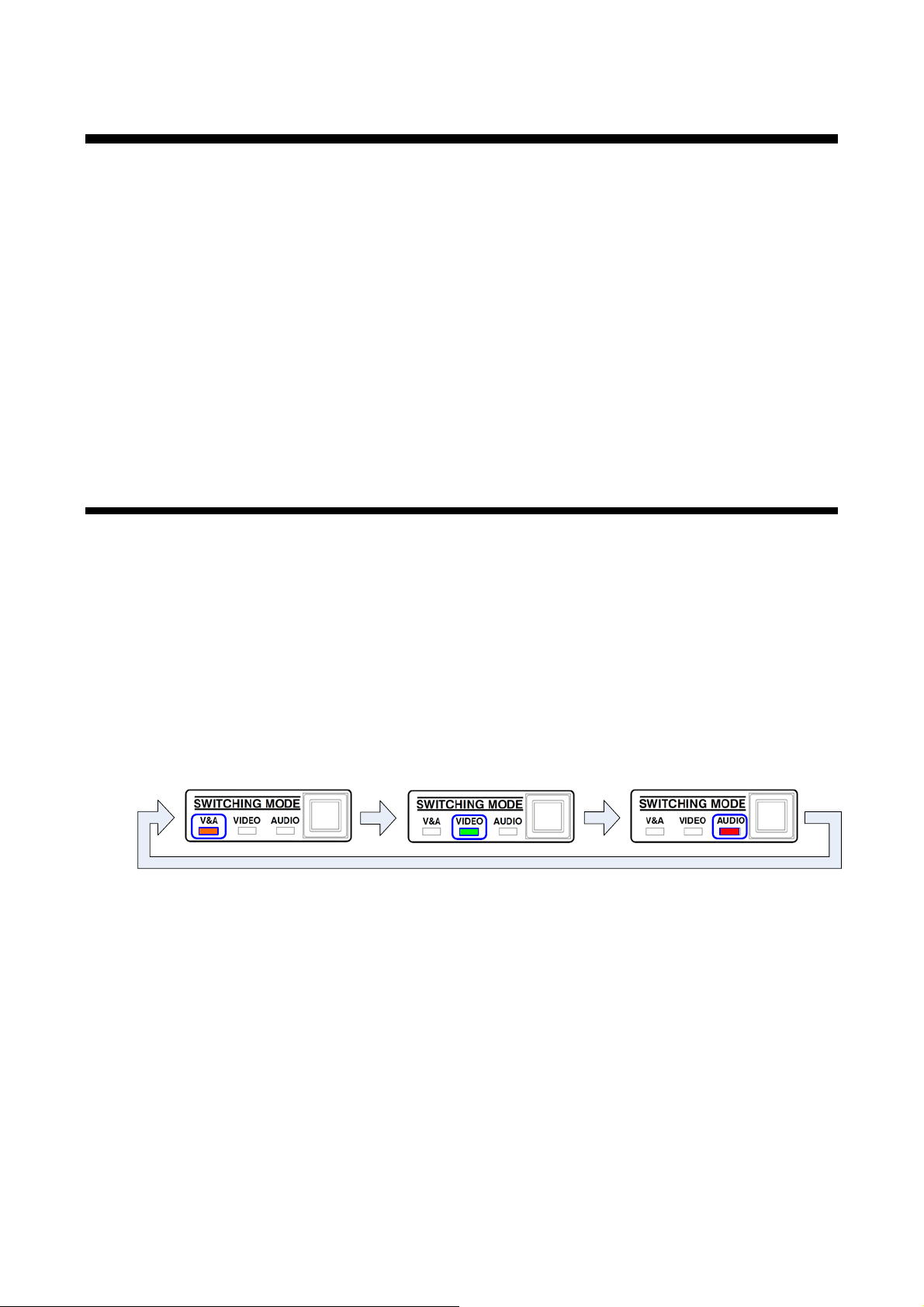
7.1 Channel switching mode
・V&A: Illuminates in orange. I/O c hannels of the FDX and MAU-1616 can be switched simultaneously .
・VIDEO: Illuminates in green. I/O channels of only the FDX can be switched.
・AUDIO: Illuminates in red. I/O channels of only the MAU-1616 can be switched.
(MAU-1616 I/O control: Up to 12 channels.)
Every time you press the key, the mode is switched. (V&A→VIDEO→AUDIO)
[Fig. 7.1] Switching channel mode
21

FDX-12UHD User’s Guide
7.2 Selecting I/O channel
You can select I/O channels using INPUT SELECT and OUTPUT SELECT keys.
If you want to select an input channel first, select “INPUT→OUTPUT” mode using the c hannel switching
direction key. In the opposite case (you want to select output channels first), select “OUTPUT→INPUT” mode.
This selection uses the channel switching directi on sel ection key.
Note:
In some system envir onm ent, EDID needs to be set in order to output video and audio to the sink device.
If video or audio is not output by following the procedure in this section, ensure the EDID setti ngs match the
sink device specification.
【See: 8.5 EDID】
22
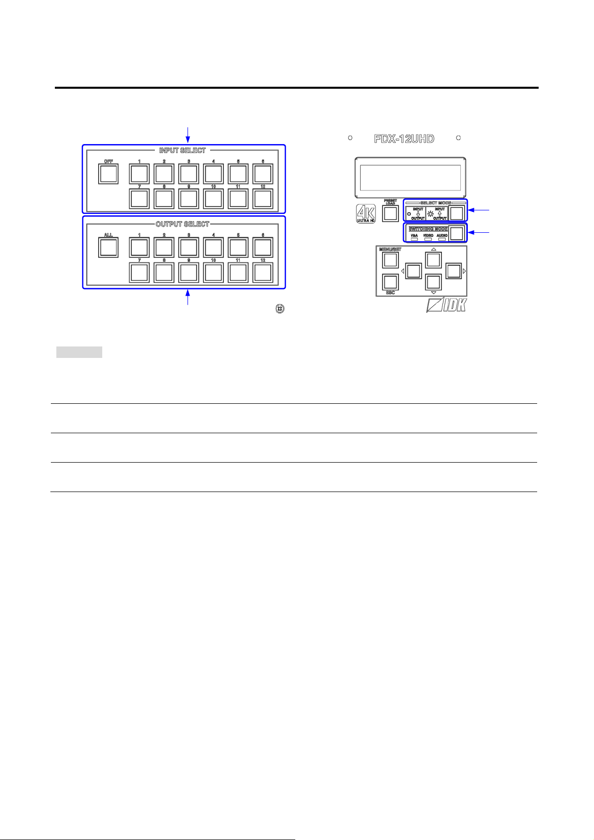
7.2.1 Selecting I/O channel in INPUT→OUTPUT mode
2
1
4
3
→
Procedure
Select the desired m ode by pressing the SWITCHING MODE key.
(LEDs of the currentl y selected output channels will be turned on.)*
Select output c hannels by pressing OUTPUT SELECT keys (“1“ to “12” or “ALL”).*
Selecting an input c hannel first and then selecting out put channels:
[Fig. 7.2] Selecting I/O channel in INP UT
OUTPUT mode
FDX-12UHD User’s Guide
1
(LEDs of input and out put channel keys that corresponding to the selec ted mode will be turned on.)
Select “ INPUT→OUTPUT” mode by pressing the SELECT MODE key.
2
(The LED of the SELECT MODE key will be turned off .)
Select an input channel by pressing an INPUT SELECT key (“1“ to “12” or “OFF”).
3
4
Notes for channel selection:
・Channels that do not have a slot boar d c annot be selected.
・The selected output channels can be OFF (no signal) by pressing the “OFF” key.
・The selected input c hannel c an be output to all output channels by pressing the “ALL” key..
23

FDX-12UHD User’s Guide
2
1
3
4
→
(LEDs of input and out put channel keys that corresponding to the selec ted mode will be turned on.)
Select “ OUTPUT→INPUT” mode by pressing the SELECT MODE key.
(The LED of the SELECT MODE key will be turned on.)
Select output c hannels by pressing OUTPUT SELECT keys (“1“ to “12” or “ALL”).
7.2.2 Selecting I/O channels in OUTPUT→INPUT mode
Selecting out put channels first and then selecting an input channel:
[Fig. 7.3] 6.2.2 Selec tin g I/O channels in OUTP UT
Procedure
Select the desired m ode by pressing the SWITCHING MODE key.
INPUT mode
1
2
3
(The LED of the currently sel ec ted input channel will be turned on.)*
Select an input channel by pressing an INPUT SELECT key (“1“ to “12” or “OFF”).*
4
Notes for channel selection:
・Channels that do not have a slot boar d c annot be selected.
・The selected output channels can be OFF (no signal) by pressing the “OFF” key.
・The selected input c hannel c an be output to all output channels by pressing the “ALL” key.
24
 Loading...