

IDK FDX-08 Command Reference Manual
POWER
DIGITAL MATRIX SWITCHER
INPUT SELECT
1 2 3 4 5 6
ALL 7 8
OUTPUT SELECT
FDX-08
1 2
3 4 5 6
OFF 7 8
V&A VIDEO AUDIO
SWITCHING MODE
MENU/SET
ESC
SELECT MODE
OUTPUT
INPUT
PRESET
OUTPUT
INPUT
LOAD
DVI-D(HDMI) DVI-D(HDMI)
A B
INPUT
~
1 4
INPUT
~
5 8
A D
A D
~
1 4
~
5 8
OUTPUT
OUTPUT
A D
A D
FG
BREAKER
AC 100-240V
50/60Hz
S/N
OPTIONRS-232C LAN
UPDATE
ALARM
DVI-D(HDMI) DVI-D(HDMI) DVI-D(HDMI) DVI-D(HDMI)
A B C D
INPUT
SDI SDI SDI SDIA B C D
LOOP OUT INPUT LOOP OUT INPUT LOOP OUT INPUT LOOP OUT
LINK LINK LINK LINK
HDBaseTA B
C DHDBaseT HDBaseT HDBaseT
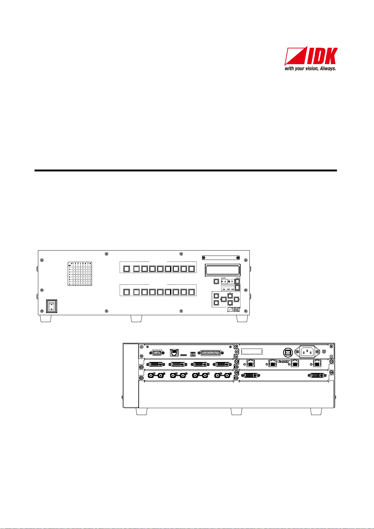
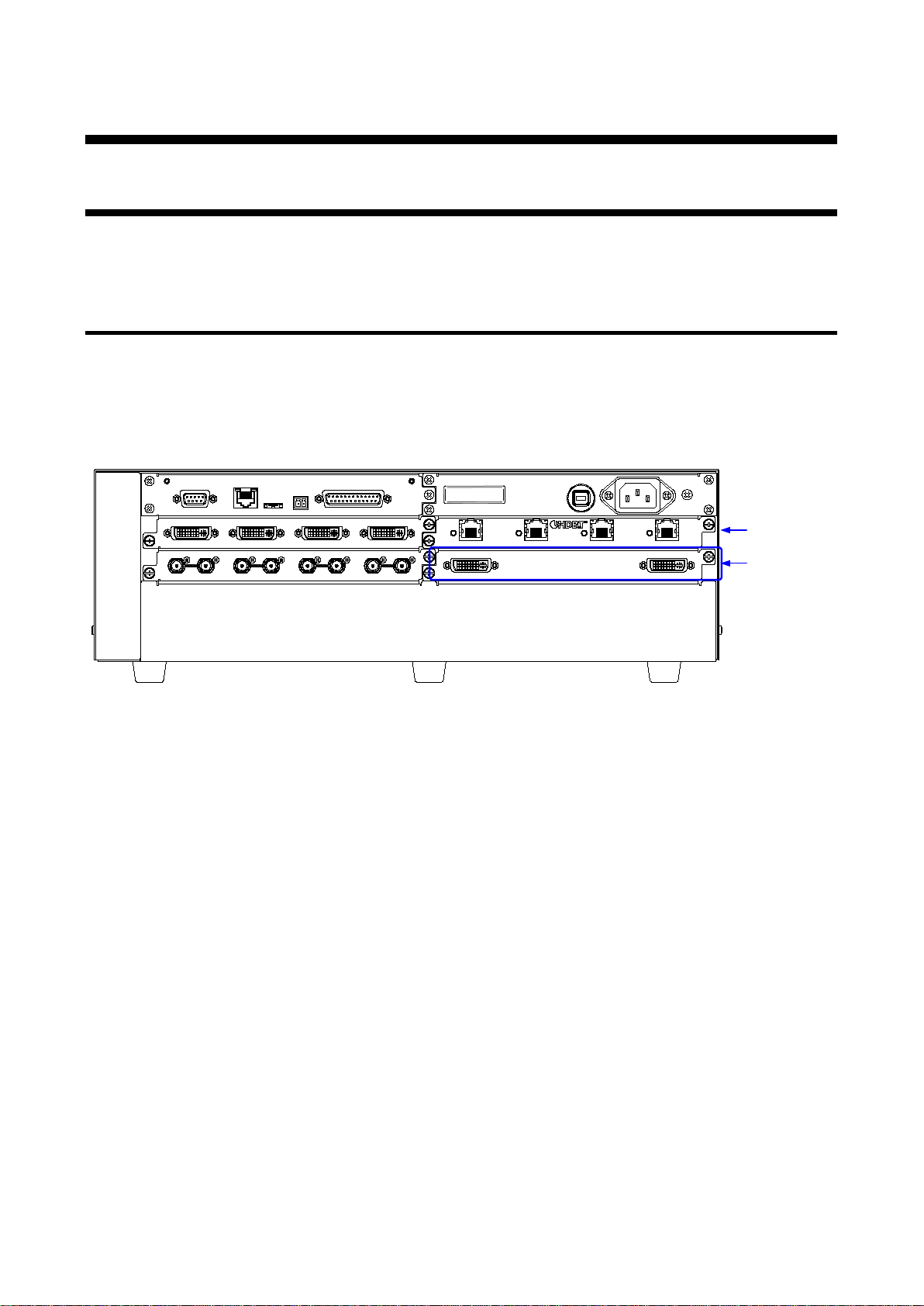
Modular Matrix Switcher
FDX-08
<Command Reference Guide>
Ver.1.0.0
Thank you for choosing our product.
To ensure the best performance of this product, please read this user guide fully and carefully before
using it and keep this manual together with the product for future reference as needed.
IDK Corporation

FDX-08 Command Guide
Trademarks
The terms HDMI and HDMI High-Definition Multimedia Interface, and the HDMI Logo are trademarks or
registered trademarks of HDMI Licensing Administrator, Inc. in the United States and other countries.
HDBaseT™ and the HDBaseT Alliance Logo are trademarks of the HDBaseT Alliance.
All other company and product names mentioned in this manual are either registered trademarks or
trademarks of their respective owners. In this manual, the “®” or “™” marks may not be specified.
2

FDX-08 Command Guide
Before reading this manual
All rights reserved.
Some information contained in this Command guide such as exact product appearance, diagrams, menu
operations, communication commands, and so on may differ depending on the product version.
This Command guide is subject to change without notice. You can download the latest version from IDK’s
website at: http://www.idkav.com
The reference manual consists of the following two volumes:
■ User guide: Please download the user manual from the website above.
Provides explanations and procedures for operations, installation, connections among devices, I/O
adjustment and settings.
■ Command guide (this doc u ment):
Provides explanations and procedures for external control using RS-232C and LAN communications.
3

FDX-08 Command Guide
Table of Contents
1 About this guide ............................................................................................................................................ 5
2 Communication specifications ...................................................................................................................... 6
2.1 RS-232C communication ...................................................................................................................... 6
2.1.1 Setup of RS-232C communication ................................................................................................ 6
2.1.2 RS-232C connector specification .................................................................................................. 8
2.1.3 RS-232C communication specification ......................................................................................... 8
2.2 LAN communication .............................................................................................................................. 9
2.2.1 LAN communication ...................................................................................................................... 9
2.2.2 LAN connector specification ........................................................................................................ 13
2.2.3 LAN communication specification ............................................................................................... 13
2.2.4 Limit on the number of TCP-IP connections and port overload management ............................ 14
3 Channel Configuration ................................................................................................................................ 15
3.1 Outline ................................................................................................................................................. 15
3.1.1 Channel of output board .............................................................................................................. 15
4 Command ................................................................................................................................................... 16
4.1 Summary ............................................................................................................................................. 16
4.1.1 Regular command ....................................................................................................................... 16
4.2 Command list ...................................................................................................................................... 17
4.3 Details of commands .......................................................................................................................... 20
4.3.1 Error status .................................................................................................................................. 20
4.3.2 I/O channel selection ................................................................................................................... 21
4.3.3 Input settings ............................................................................................................................... 24
4.3.4 Input timing settings .................................................................................................................... 28
4.3.5 Output settings ............................................................................................................................ 40
4.3.6 Output timing settings ................................................................................................................. 43
4.3.7 Audio ........................................................................................................................................... 56
4.3.8 EDID settings .............................................................................................................................. 57
4.3.9 RS-232C communication ............................................................................................................ 62
4.3.10 LAN communication .................................................................................................................... 63
4.3.11 Preset memory ............................................................................................................................ 65
4.3.12 Others .......................................................................................................................................... 68
4.3.13 RS-232C transmission mode ...................................................................................................... 76
4
FDX-08 Command Guide
POWER
DIG I TAL MATRIX SWITCHER
INPUT SELECT
1 2 3 4 5 6
ALL 7 8
OUTPUT SELECT
FDX-08
1 2 3 4 5 6
OFF 7 8
V&A VIDEO AUDIO
SWITCHING MODE
MENU/SET
ESC
SELECT MODE
OUTPUT
INPUT
PRESET
OUTPUT
INPUT
LOAD
FDX-08
LAN communication
Control via commands
Control via WEB browser
PC PC
PC
RS-232C
communication
Control via commands
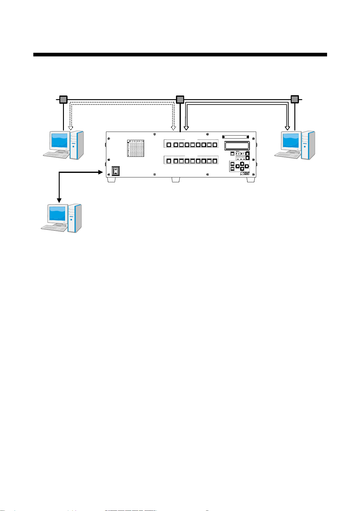
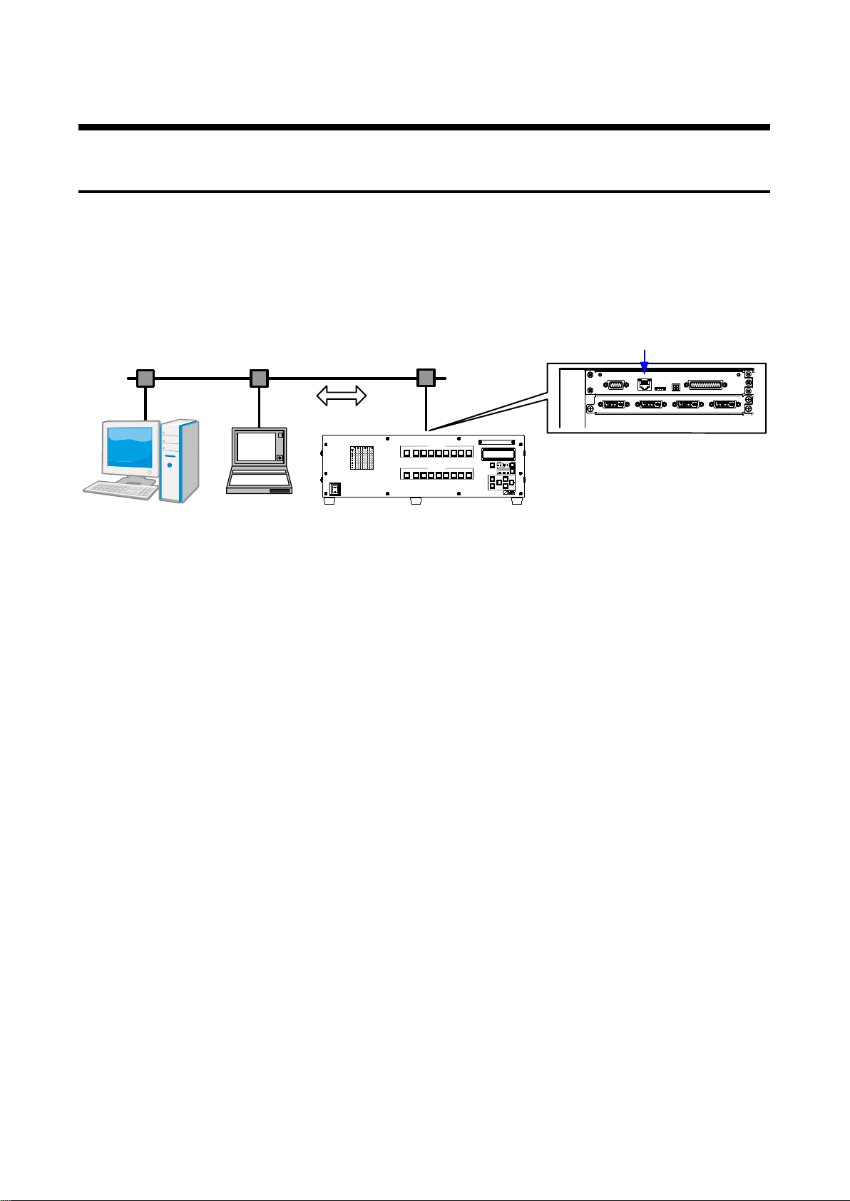
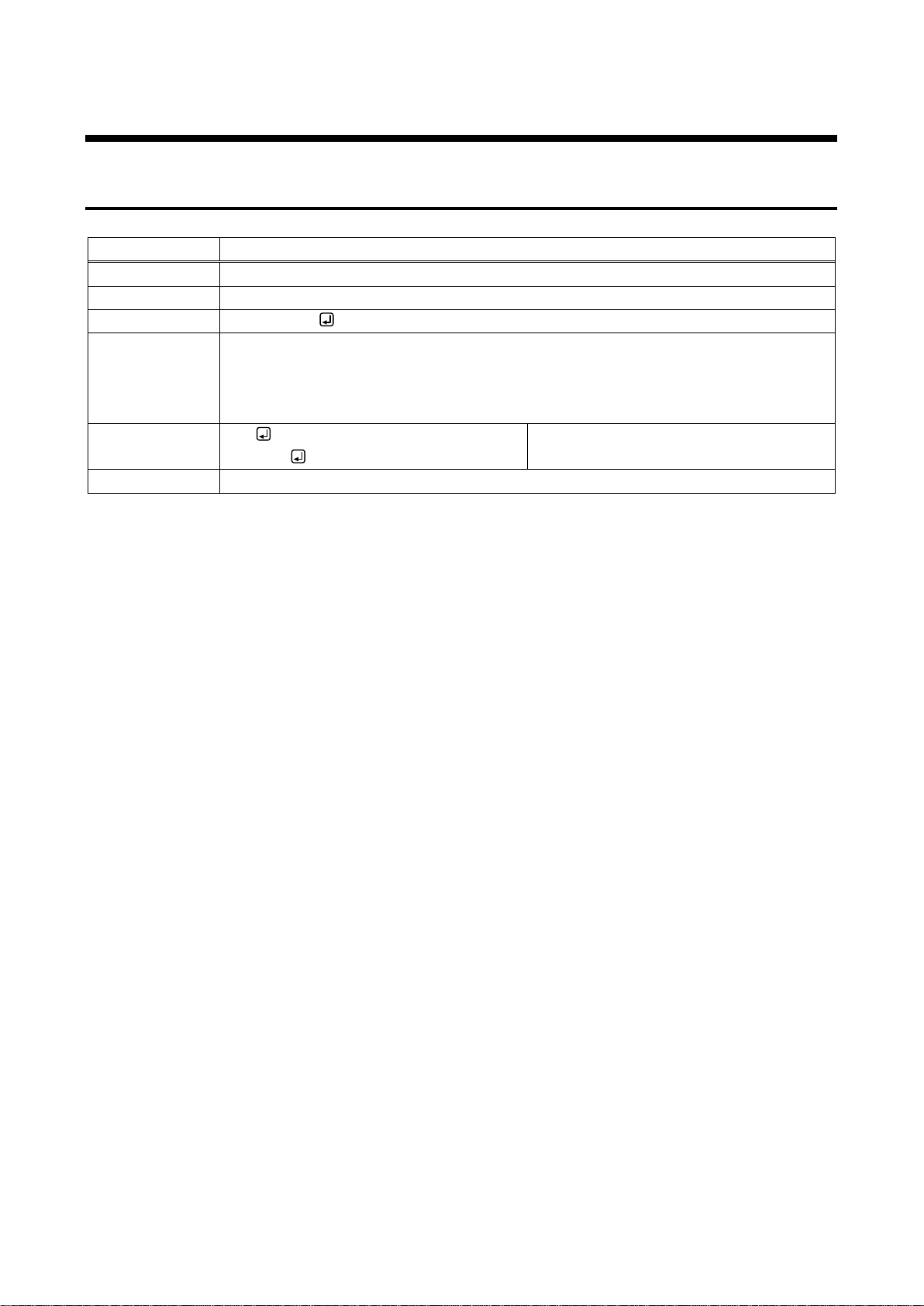
1 About this guide
This guide contains the procedure for controlling FDX using commands via RS-232C communication or LAN
communication.
[Fig. 1.1] External control
Communication commands enables the following main operations:
・Switching channels
・Setting input, output, audio, and EDID
・Recalling and saving preset memory
5
FDX-08 Command Guide
INPUT
~
1 4
A D
OPTION
RS-232C
LAN
UPDAT E
ALA RM
DVI-D (HDM I)
DVI-D (HDM I)
DVI-D (HDM I) DVI-D (HDM I)
A
B
C D
FDX-08
PC
RS-232C cable
Command
RS-232C connector
POWER
DIG ITAL M ATRIX SWITCH ER
INPUT SELECT
1
2
3 4
5 6
ALL 7
8
OUTPUT SELECT
FDX-08
1 2
3 4
5
6
OFF
7 8
V&A VID EO AUDIO
SWITCHING MODE
MENU/SET
ESC
SELECT MODE
OUTPUT
INPUT
PRESET
OUTPUT
INPUT
LOAD
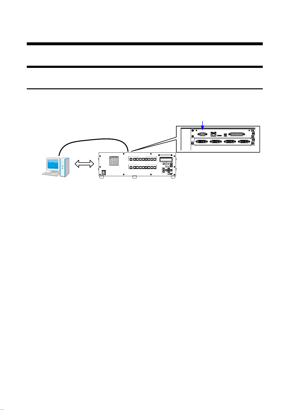
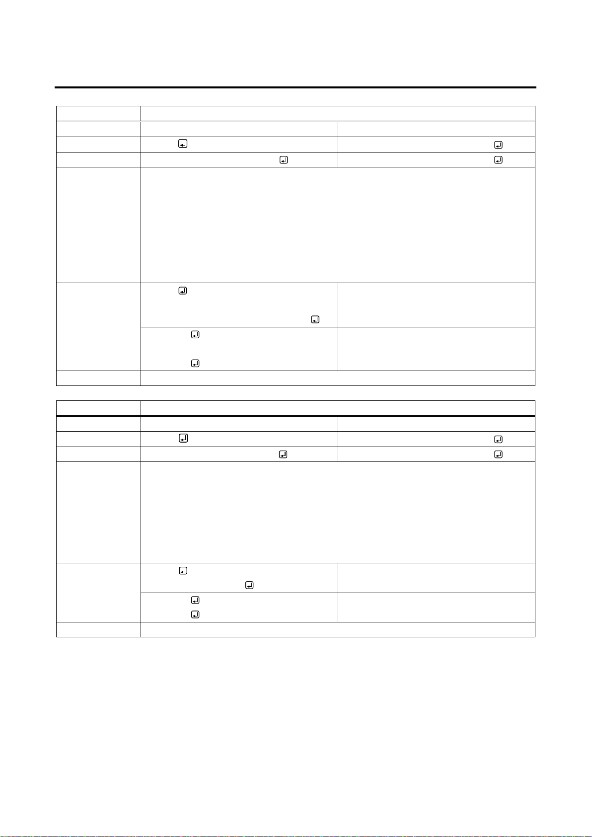
2 Communication specifications
2.1 RS-232C communication
2.1.1 Setup of RS-232C communication
The FDX can be controlled via RS-232C communication. Connect the FDX with a control device (such as PC)
via an RS-232C cable and use commands to control the FDX or acquire its status.
[Fig. 2.1] Connecting control device via RS-232C
6
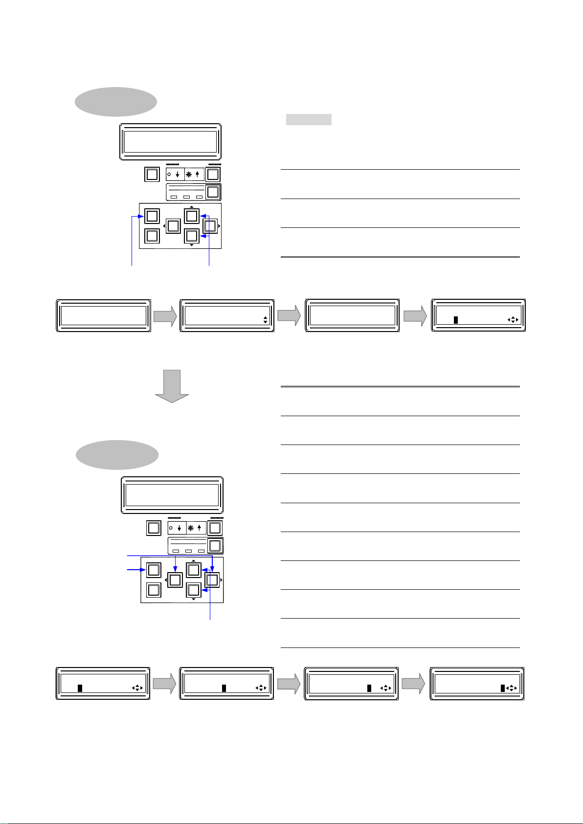
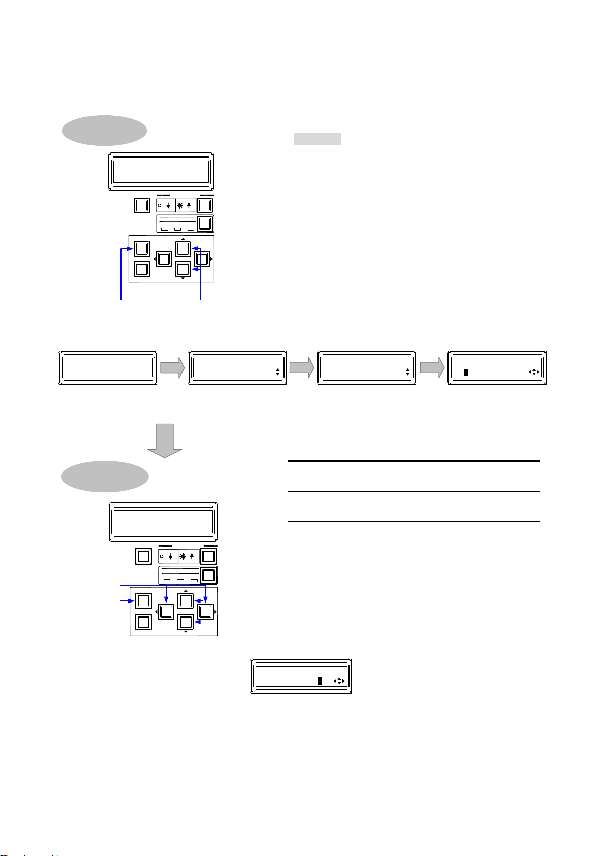
To set RS-232C communication:
Procedure
Press the “MENU/SET” key to open the main
“COM PORT”.
rate.
Use the “” and “” keys to move the cursor
length.
to the stop bit.
Use “▲” and “▼” keys to select the stop bit.
settings.
5, 6 7, 8 9, 10
Baud rat e
Dat a bit length
Parity check Stop bit
11, 12, 13
[COM PORT SETUP]
9600bps 8 NONE 1
[COM PORT SETUP]
9600bps 8 NONE 1
[COM PORT SETUP]
9600bps 8 NONE 1
[COM PORT SETUP]
9600bps 8 NONE 1
6, 8, 10, 12
5, 7, 9, 11
Changing setting
V&A V IDEO A UDI O
SWITCHING MODE
MENU /SET
ESC
SELECT MODE
OUTPUT
INP UT
PRESET
OUTPUT
INP UT
LOAD
13
Selecting menu
21, 3, 4
V&A V IDEO A UDI O
SWITCHING MODE
MENU /SET
ESC
SELECT MODE
OUTPUT
INP UT
PRESET
OUTPUT
INP UT
LOAD
[FUNCT ION SELECT]
COM PORT
[COM PORT]
COM P ORT SETUP
2, 3 4
Main menu
Sub m enu
Setting screen
[COM PORT SETUP]
9600bps 8 NONE 1
FDX-08
08x08 Matrix
1
Top screen
【See: 2.1.3 RS-232C communication specification】
1
menu.
Use “▲” and “▼” keys to select
2
Press the “MENU/SET” key to move to the
3
sub menu.
Press the “MENU/SET” key to move the
4
“COM PORT SETUP” screen.
Use the “” and “” keys to move the cursor
5
to the baud rate.
Use “▲” and “▼” keys to select the baud
6
7
to the data bit length.
Use “▲” and “▼” keys to select the data bit
8
Use the “” and “” keys to move the cursor
9
to the parity check.
Use “▲” and “▼” keys to select the parity
10
check.
Use the “” and “” keys to move the cursor
11
12
Press the “MENU/SET” key to apply the
13
[Fig. 2.2] Setup RS-232C communication
FDX-08 Command Guide
7
FDX-08 Command Guide
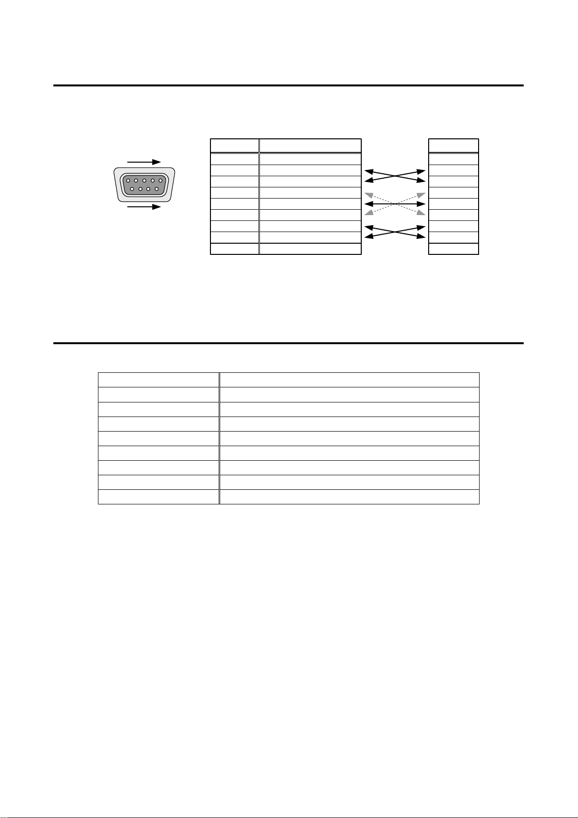
Male D-sub (9 pin)
1
5
RS-232C connect or
6
9
RD
TD
N.C.
N.C.
N.C.
N.C.
GND
RTS
CTS
Pin#
1
3
2
4
6
5
7
9
8
Signal
RD
TD
N.C.
N.C.
N.C.
N.C.
GND
RTS
CTS
Signal
(Received data )
(Transmitted data)
(Ground)
(Request to Send)
(Clear to Send)
FDX
Cross cable
Control device
(Rear panel)
(No connection )
(No connection )
(No connection )
(No connection )
Compliant standard
RS-232C
Baud rate
4800, 9600, 14400, 19200, 38400 [b ps]
Data bit length
7, 8 [bit]
Parity check
NONE, EVEN, ODD
Stop bit
1, 2 [bit]
2.1.2 RS-232C connector specification
RS-232C pin assignments
[Fig. 2.3] RS-232C connector
2.1.3 RS-232C communication specification
[Table 2.1] RS-232C specification
X parameter Invalid
Flow control None
Delimiter CR LF (Carriage return and line feed, 0D and 0A in hex)
Communication method Full duplex
8
FDX-08 Command Guide
LAN connector
LAN
Command
INPUT
~
1 4
A D
OPTION
RS-232C
LAN
UPDAT E
ALARM
DVI-D (HDM I)
DVI-D (HDM I)
DVI-D (HDM I) DVI-D(HDM I)
A
B
C D
FDX-08
POWER
DIG ITAL MA TRIX SWITCHER
INPUT SELECT
1
2 3 4
5 6
ALL 7
8
OUTPUT SELECT
FDX-08
1 2
3
4 5
6
OFF
7 8
V&A
VIDEO AUDIO
SWITCHING MODE
MENU/SET
ESC
SELECT MODE
OUTPUT
INPUT
PRESET
OUTPUT
INPUT
LOAD
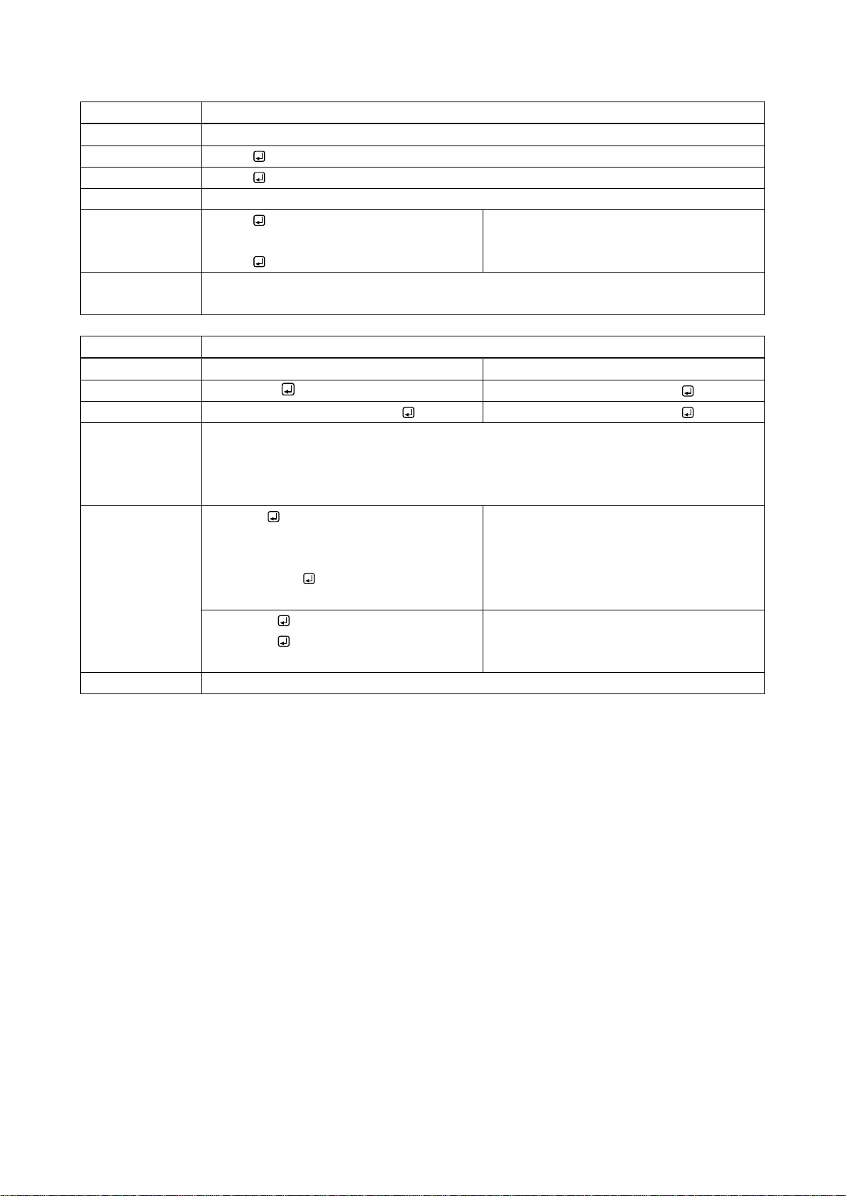
2.2 LAN communication
2.2.1 LAN communication
The FDX can be controlled via LAN communication. Connect the FDX with a control device (such as PC) via
an LAN cable and use commands to control the FDX and acquire its status.
For command control, use ports 6000 to 6999 or 1100. If no command is sent for 30 seconds after connection
established, the connection will be disconnected.
[Fig. 2.4] LAN connection
9
FDX-08 Command Guide
menu.
menu.
Press the “MENU/SET” key to open the setting
each digit.
8
settings.
7
6
8
V&A VIDEO AUD IO
SWITCHING MODE
MENU /SET
ESC
SELECT MODE
OUTPUT
INP UT
PRESET
OUTPUT
INP UT
LOAD
Changing setting
Selecting menu
2, 41, 3, 5
V&A V IDEO A UDI O
SWITCHING MODE
MENU /SET
ESC
SELECT MODE
OUTPUT
INP UT
PRESET
OUTPUT
INP UT
LOAD
6, 7, 8
Setting IP address
[IP ADDRESS]
192.168.001.199
[LAN]
IP ADDR ESS
2, 3 4, 5
Main menu Sub m enu
Setting menu
[FUNCT ION SELECT]
LAN
[IP ADDR ESS]
192.168.001.1 99
FDX-08
08x08 Matrix
1
Top screen
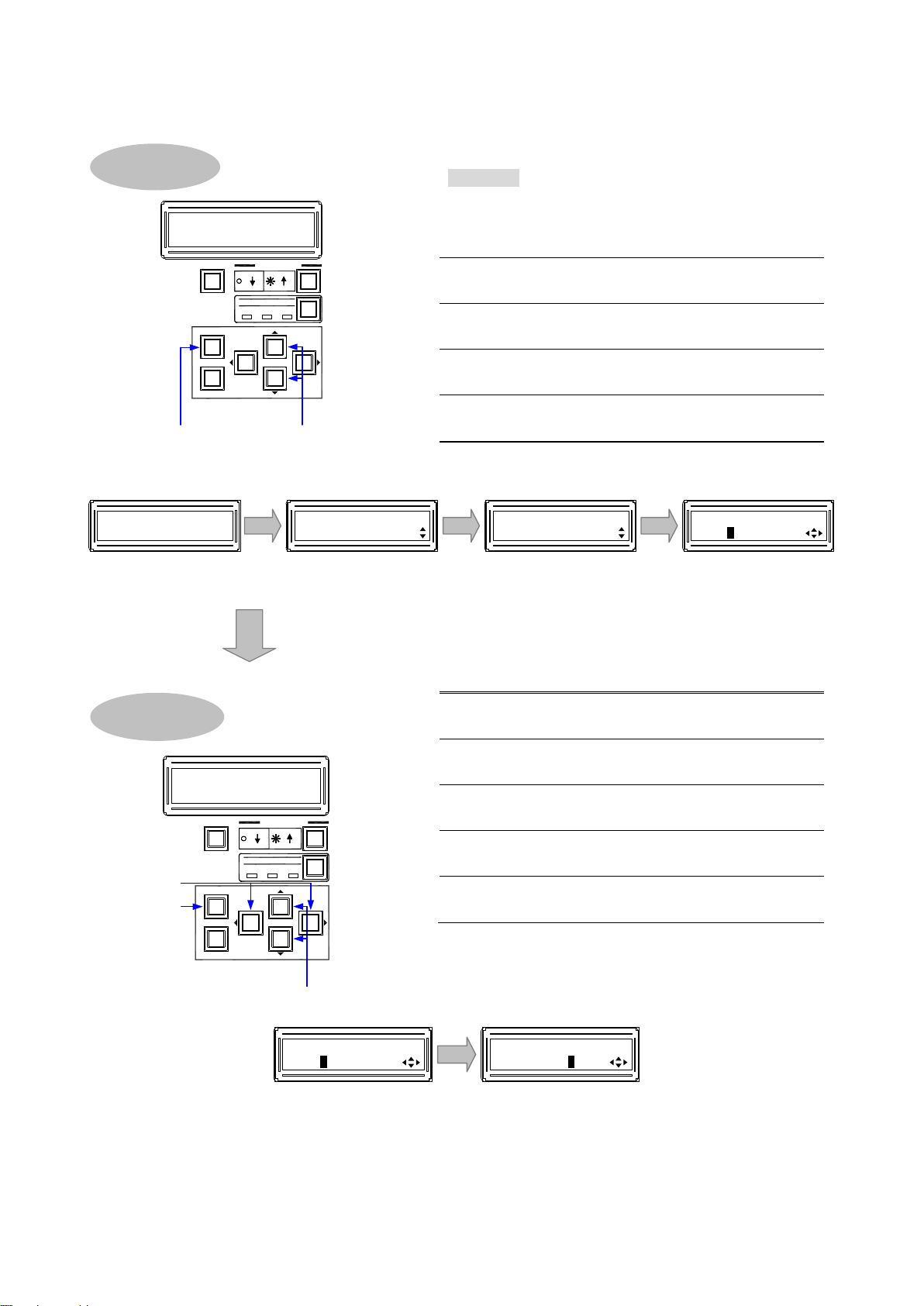
To set LAN communication: Setting IP address, subnet mask, and port number:
■ IP address
10
Procedure
Press the “MENU/SET” key to open the main
1
Use “▲” and “▼” keys to select “LAN”.
2
Press the “MENU/SET” key to open the sub
3
Use “▲” and “▼” key s to sel ect “IP ADDRESS”.
4
5
screen.
Use the “” and “” keys to move the cursor to
6
Use “▲” and “▼” keys to select the value.
7
Press the “MENU/SET” key to apply the
[Fig. 2.5] Setting IP address

■ Subnet mask
menu.
Use “▲” and “▼” keys to select “LAN”.
menu.
Press the “MENU/SET” key to open the setting
settings.
6, 7
Setting subnet mask
[SUBNET MASK]
255.255.255.000
[FUNCT ION SELECT]
LAN
[LAN]
SUBNE T MASK
2, 3
4, 5
Main menu
Sub m enu
[SUBNE T MASK]
255.255.255.000
Setting screen
FDX-08
08x08 Matrix
1
Top screen
Selecting menu
2, 41, 3, 5
V&A V IDEO A UDI O
SWITCHING MODE
MENU /SET
ESC
SELECT MODE
OUTPUT
INP UT
PRESET
OUTPUT
INP UT
LOAD
6
7
V&A VIDEO AUD IO
SWITCHING MODE
MENU /SET
ESC
SELECT MODE
OUTPUT
INP UT
PRESET
OUTPUT
INP UT
LOAD
Changing setting
Procedure
Press the “MENU/SET” key to open the main
1
2
Press the “MENU/SET” key to open the sub
3
Use “▲” and “▼” keys to select
4
“SUBNET MASK”.
5
screen.
Use “▲” and “▼” keys to select the value.
6
Press the “MENU/SET” key to apply the
7
[Fig. 2.6] Setting subnet mask
FDX-08 Command Guide
11
FDX-08 Command Guide
menu.
Press the “MENU/SET” key to open the sub
PORT”.
Press the “MENU/SET” key to open the
to the 8 connection setting (“2”).
Use “▲” and “▼” keys to select “OFF” or
settings.
[CONTROL PORT]
1:1100 2:OFF
8, 9, 10
Setting 8 connection (“2”)
6, 7
Setting port number (“1”)
[CONTROL PORT]
1:1100 2:OFF
[FUNCT ION SELECT]
LAN
[LAN]
CONTROL PORT
2, 3
4, 5
Main menu
Sub m enu
FDX-08
08x08 Matrix
1
Top screen
[CONTROL PORT]
1:1100 2:OFF
Setting menu
Selecting menu
2, 41, 3, 5
V&A V IDEO A UDI O
SWITCHING MODE
MENU /SET
ESC
SELECT MODE
OUTPUT
INP UT
PRESET
OUTPUT
INP UT
LOAD
7, 9
6, 8
10
V&A VIDEO AUD IO
SWITCHING MODE
MENU /SET
ESC
SELECT MODE
OUTPUT
INP UT
PRESET
OUTPUT
INP UT
LOAD
Changing setting
■ TCP port number
Procedure
Press the “MENU/SET” key to open the main
1
Use “▲” and “▼” keys to select “LAN”.
2
3
menu.
Use “▲” and “▼” keys to select “CONTROL
4
5
setting screen.
Use the “” and “” keys to move the cursor
6
to the port number (“1”).
Use “▲” and “▼” keys to select the port
7
number.
Use the “” and “” keys to move the cursor
8
9
“ON”.
Press the “MENU/SET” key to apply the
10
[Fig. 2.7] Setting TCP port number
12

FDX-08 Command Guide
Physical la yer
10Base-T (IEEE802.3i)/100Base-TX (IEEE802.3u)
RX+
N.C.
TX+
Pin #
1
3
2
4
6
5
7
8
Signal name
TX-
N.C.
RX-
N.C.
N.C.
(Transmitted Data +)
(Transmitted Data -)
(Received Data +)
(No connection)
(Received Data -)
(No connection)
(No connection)
81
LAN connector
8 pin RJ-45 connector
(FDX’s rear panel)
(No connection)
Illuminates in green when the
link is established.
Illuminates in orange when data can be sent/received.
Blinks in orange while data is being sent/received.
MDI
TX+
N.C.
RX+
RX-
N.C.
TX-
N.C.
N.C.
(Received Data +)
(Received Data -)
(Transmitted Data +)
(No connection)
(Transmitted Data -)
(No connection)
(No connection)
(No connection)
MDI-X
2.2.2 LAN connector specification
LAN connector assignments are as follows.
Since Auto MDI/MDI-X that distinguishes and switches straight/cross cables automatically is supported, extra
care is not necessary to connect the FDX to PC, HUB or the like.
[Fig. 2.8] LAN connector
2.2.3 LAN communication specification
Network layer ARP, IP, ICMP
Transport layer
Application layer HTTP, TELNET
Note:
Up to 8 connections can be used simultaneously for command control (4 connections for WEB browser).
[Table 2.2] LAN communication
TCP
Port used for command control : 1100, 6000 to 6999
Port used for WEB browser control (HTTP) : 80
【See: 2.2.4 Limit on the number of TCP-IP connections and port overload management】
13

FDX-08 Command Guide
Your PC software
FDX-08
2.2.4 Limit on the number of TCP-IP connections and port overload management
The FDX’s maintenance port supports a maximum of eight simultaneous connections (eight logical ports).
To maintain optimal system accessibility, it is advisable to issue “port-open” and “port-close” commands
before and after command or query strings are issued. This approach enables eight or more control devices to
be effectively interfaced simultaneously and without concern for communication errors.
[Table 2.3] Increasing connections
TCP-IP connection → (1 port occupied)
Send command (@xxx) →
← The command (@xxx) replied
TCP-IP close → (1 port released)
Note:
If no command is sent from the PC side to the FDX for 30 seconds, the FDX automatically disconnects from
that device. As a result, connection needs to be established again from the PC side after connection of the PC
is disconnected. (Since the number of ports in the FDX is eight, ports are occupied permanently if the PC is
turned off while connections are valid. To prevent this, the FDX disconnects connections if no communication
command is sent from the PC side.)
14
FDX-08 Command Guide
DVI-D(HDMI) DVI-D(HDMI)
A B
INPUT
~
1 4
INPUT
~
5 8
A D
A D
~
1 4
~
5 8
OUTPUT
OUTPUT
A D
A D
FG
BREAKER
AC 100-240V
50/60Hz
S/N
OPTIONRS-232C LAN
UPDATE
ALARM
DVI-D(HDMI) DVI-D(HDMI) DVI-D(HDMI) DVI-D(HDMI)
A B C D
INPUT
SDI SDI SDI SDIA B C D
LOOP OUT INPUT LOOP OUT INPUT LOOP OUT INPUT LOOP OUT
LINK LINK LINK LINK
HDBaseTA B C DHDBaseT HDBaseT HDBaseT
1 2 3 4
5 6
Digital scan
converter output
board (2 outputs)
HDBaseT output
board (4 outputs)
3 Channel Configuration
3.1 Outline
An I/O board has four channels.
An output board has four channels or two channels (scan converter output board).
3.1.1 Channel of output board
・ The channel numbers of scan converter output board are the first two channels only; the rest of two
channels cannot be set.
・ In the configuration shown below, valid channels and invalid channels are as follows.
Digital scan converter output board: No.5 and 6 are valid; No.7 and 8 are not used.
[Fig. 3.1] Channel configuration of Output board
15

FDX-08 Command Guide
4 Command
4.1 Summary
4.1.1 Regular command
A command consists of “@” (“40” in hexadecimal), 3 one-byte alphabetical characters (upper and lower
cases) followed by parameters (one-byte numbers). For some commands, multiple parameter values can be
specified or parameters are not necessary. Processing is executed by sending a delimiter at the end of the
command.
Example: @SPM,2
“,”(a comma, “2C” in hex) is indicated between a command and parameter and between two parameters.
“ ” is indicated as a delimiter CR LF (return+line feed, “0D” and “0A” in hex).
An error response is returned if an undefined command or inappropriate parameter is included.
Example: @SSW,1
@ERR,1
If only a delimiter is sent, a list of help commands is returned.
Example:
- HELP (1/8) - (CHANNEL SELECT Command)
@IOS : Input/Output Select
@GVA : Getting Cross Poi nt Video and Audio
@IOV : Input/O utp ut Vi deo Se lect
@GCP : Getting Cross Point Video
@IOA : Input/O utp ut Aud io Se lect
16

FDX-08 Command Guide
@ERR
Error status
20
@GCY / @SCY
Input channel selection copy
23
@GHU / @SHU
Input HUE
35
@GSR / @SSR
Input saturation
36
@GEF / @SEF
Input video settings
37
4.2 Command li st
Error status
Command Function Page
I/O channel selection
Command Function Page
@GVA / @IOS Switching I/O channels of FDX and MAU-1616 (optional) simultaneously 21
@GCP / @IOV Switching only FDX I/O channels 21
@GCA / @IOA Switching only MAU-1616 I/O channels 22
@SSC Straight Switching* I/O channel of FDX and MAU-1616 22
@SSV Straight Switching* I/O channel of FDX 22
@SSA Straight Switching* I/O channel of MAU-1616 23
Input settings
Command Function Page
@GIQ / @SIQ Input equalizer 24
@GDT / @SDT No-signal-input monitoring 24
@GHE / @SHE HDCP input enabled/disab led 25
@GAG / @SAG SDI input audio group 26
@GDU / @SDU SDI Dual Stream input video 27
Input timing settings
Command Function Page
@GPI / @SPI Input video start position 28
@GSI / @SSI Input video active area 29
@GAP / @SAP Input video aspect ratio 30
@GIC / @SIC Input contrast 31
@GIB / @SIB Input brightness 32
@GGM / @SGM Input gamma 33
@GFL / @SFL Input sharpness 34
Output settings
Command Function Page
@GEQ / @SEQ Output equalizer 40
@GDM / @SDM Output mode 40
@GHM / @SHM Sink device EDID check 41
@GMK / @SMK Hot plug ignoring duration 42
@GDC / @SDC Output Deep Color 42
17

FDX-08 Command Guide
@GMR / @SMR
Display size/position
46
@GBC / @SBC
Blank color/Background color
47
@GOC / @SOC
Output contrast
48
@GOB / @SOB
Output brightness
49
@GFA / @SFA
Dissolve effect
50
@GEN / @SEN
HDCP output
51
@GOA / @SOA
Output setting
52
@GDO / @SDO
Digital audio output
56
Command
Function
Page
@GIP / @SIP
IP address
63
@GSB / @SSB
Subnet mask
63
Command
Function
Page
@RPM
Recalling preset memory
65
@SPM
Saving preset memory – [D] Delete
65
@SEM
Saving preset memory – [C] Continue
66
@GCM / @ECM
Editing preset memory
66
Output timing settings
Command Function Page
@GOT / @SOT Output resolution 43
@GUM / @SUM Aspect ratio of sink device 44
@GTP / @STP Output test pattern 45
Audio
Command Function Page
EDID
Command Function Page
@GED / @SED EDID resolution 57
@RME Copying EDID 58
@GEC / @SEC EDID loading output channel 58
@GDI / @SDI Deep Color input 59
@GSP / @SSP The number of audio channels 60
@GAF / @SAF Audio format 61
RS-232C communication
Command Function Page
@GCT / @SCT RS-232C communication 62
LAN communication
@GLP / @SLP TCP port number 64
@GMC MAC address 64
Preset memory
@GPM Preset memory number matching current I/O channel status 67
18

FDX-08 Command Guide
@GIV
Version
69
@GIS
Input signal status (For each channel)
70
@GII
Input signal status
71
@GOS
Sink device status (For each channel)
73
@GOI
Sink device status
74
@GFS
Cooling fan status
75
@GPS
Voltage status
75
@G++ / @S++
RS-232C transmission sending channel
78
@G+R / @S+R
RS-232C transmission receiving channel
78
@S+S
RS-232C transmission
78
Others
Command Function Page
@GLM / @SLM Front key function lock 68
@GST Board status 68
@GSS Board mounting status 69
RS-232C transmission mode
Command Function Page
19
FDX-08 Command Guide
@ERR
Error status
@ERR, error
@ERR,2
Command format error
Remarks
4.3 Details of commands
4.3.1 Error status
Function Getting
Format Return value only
Return value
Parameter error: Error status
1 = Erroneous parameter format or value
2 = Undefined command or wrong format
4 = Loading EDID from the sink device failed
Example
IOS
-
Sending @IOS command
20
4.3.2 I/O channel selection
@GVA / @IOS
Switching I/O channels of FDX and MAU-1616 (optional) simultaneously
Function
Getting
Setting
Format
@GVA
@IOS,in_1,out_1 (,in_2,out_2
)
Return value
@GVA,v_1,a_1,
v_8,a_8
@IOS,in_1,out_1 (,in_2,out_2
)
0 = OFF [Default], 1 to 8 = INPUT1 to INPUT8, - 1 = Board is not mounted.
@GVA
@GVA,1,1,2,2,3,3,4,4,5,5,6,6,7,7,8,8
INPUTs1 to 8
@IOS,1,3
@GCP / @IOV
Switching only FDX I/O channels
0 = OFF [Default], 1 to 8 = INPUT1 to INPUT8, - 1 = Board is not mounted.
Example
@GCP
Getting I/O channel statuses of FDX
@IOV,1,3
Completed
・・・
Parameter in_1 to in_8: Input channels of FDX and MAU-1616
0 = OFF, 1 to 8 = INPUT1 to INPUT8
out_1 to out_8: output channels of FDX and MAU-1616
0 = All outputs, 1 to 8 = OUTPUT1 to OUTPUT8
v_1 to v_8: FDX output channel
a_1 to a_8: MAU-1616 output channel
FDX-08 Command Guide
・・・
・・・
Example
@IOS,1,3
Remarks -
Function Getting Setting
Format
Return value @GCP,v_1,v_2, ・・・ v_7,v_8 @IOV,in_1,out_1 (,in_2,out_2・・・)
Parameter in_1 to in_8: FDX input channel
@GCP
0 = OFF, 1 to 8 = INPUT1 to INPUT8
out_1 to out_8: FDX output channel
0 = All outputs, 1 to 8 = OUTPUT1 to OUTPUT8
v_1 to v_8: FDX output channel
Getting I/O channel statuses of FDX and
MAU-1616
Setting OUTPUT3 of FDX and MAU-1616
to INPUT1
Completed
@IOV,in_1,out_1 (,in_2,out_2・・・)
@GCP,1,2,3,4,5,6,7,8
@IOV,1,3
Remarks -
INPUTs1 to 8
Setting FDX OUTPUT3 to INPUT1
21

FDX-08 Command Guide
@GCA / @IOA
Switching only MAU-1616 I/O channels
@GCA
Parameter
in_1 to in_8: MAU-1616 input channel
0 = OFF [Default], 1 to 8 = INPUT1 to INPUT8, - 1 = Board is not mounted.
@GCA
@SSC
Straight Switching* I/O channel of FDX and MAU-1616
Completed
Remarks
*Straight switching: For example, OUTPUT1 is connected to INPUT1; OUTPUT2 is
@SSV
Straight Switching* I/O channel of FDX
Completed
Remarks
*Straight switching: For example, OUTPUT1 is connected to INPUT1; OUTPUT2 is
Function Getting Setting
Format
Return value @GCA,a_1,a_2, ・・・ a_7,a_8 @IOA,in_1,out_1 (,in_2,out_2・・・)
0 = OFF, 1 to 8 = INPUT1 to INPUT8
out_1 to out_8: MAU-1616 output channel
0 = All outputs, 1 to 8 = OUTPUT1 to OUTPUT8
a_1 to a_8: MAU-1616 output channel
@IOA,in_1,out_1 (,in_2,out_2・・・)
Example
@GCA,1,2,3,4,5,6,7,8
@IOA,1,3
@IOA,1,3
Remarks -
Function Setting
Format
Return value
Parameter -
Example
Function Setting
Format
Return value
Parameter -
Example
@SSC
@SSC
@SSC
@SSC
connected to INPUT2; OUTPUT8 is connected to INPUT8.
@SSV
@SSV
@SSV
@SSV
Getting I/O channel statuses of MAU-1616
INPUTs1 to 8
Setting MAU-1616 OUTPUT3 to INPUT1
Completed
Setting I/O channels of FDX and
MAU-1616 to the same number I/O
Setting I/O channel of FDX to the same
number I/O
connected to INPUT2; OUTPUT8 is connected to INPUT8.
22
@SSA
Straight Switching* I/O channel of MAU-1616
Parameter
Example
@SSA
Setting I/O channel of MAU-1616 to the
Completed
Remarks
*Straight switching: For example, OUTPUT1 is connected to INPUT1; OUTPUT2 is
@GCY / @SCY
Input channel selection copy
@GCY,sch
Return value
@GCY,sch,dch_1,
dch_8
@SCY,sch,dch_1 (,dch_2
)
Parameter
sch : Source output channel
@SCY,1,3
Copying crosspoint of OUTPUT1 to
Completed
Remarks
Supported since firmware ver.2.xx
Function Setting
Format
Return value
@SSA
@SSA
-
FDX-08 Command Guide
@SSA
connected to INPUT2; OUTPUT8 is connected to INPUT8.
Function Getting Setting
Format
1 to 8 = OUTPUT1 to OUTPUT8
dch_1 to dch_8: Destination output channels
0 = All outputs, 1 to 8 = OUTPUT1 to OUTPUT8
Example
@GCY,1
@GCY,1,2,3,4
@SCY,1,3
・・・
same number I/O
@SCY,sch,dch_1 (,dch_2・・・)
Getting the output channel with the same
setting as the input channel assigned to
output channel 1
OUTPUTs 2, 3, and 4 have the same
input channel as output channle1.
OUTPUT3
・・・
23

FDX-08 Command Guide
@GIQ / @SIQ
Input equalizer
Function
Getting
Setting
Format
@GIQ
@SIQ,in_1,level_1 (,in_2,level_2
)
Return value
@GIQ,level_1,
level_8
@SIQ,in_1,level_1 (,in_2,level_2
)
-1 = Input board is not mounted or SDI input board is mounted.
Example
@GIQ
Getting the input equalizer status
@GDT / @SDT
No-signal-input monitoring
Function
Getting
Setting
Format
@GDT
@SDT,in_1,time_1 (,in_2,time_2
)
Return value
@GDT,time_1,
time_8
@SDT,in_1,time_1 (,in_2,time_2
)
- 1 = Input board is not mounted or SDI input board is mounted.
Example
@GDT
Getting settings of non-signal-input
All input channels: 10 sec.
@SDT,0,4
Setting the monitoring time of all input
Completed
Remarks
4.3.3 Input settings
・・・
Parameter in_1 to in_8: Input channel
0 = All inputs, 1 to 8 = INPUT1 to INPUT8
level_1 to level_8: Input equalizer of each input channel
0 = OFF, 1 = AUTO [Default],
・・・
・・・
Remarks -
Parameter in_1 to in_8: Input channel
@GIQ,1,1,1,1,1,1,1,1
@SIQ,0,0
@SIQ,0,0
0 = All inputs, 1 to 8 = INPUT1 to INPUT8
time_1 to time_8: Non-signal-input monitoring time of each input channel
0 = OFF, 3 to 15 = 3 sec. to 15 sec. [Default] 10 sec.,
@GDT,10,10,10,10,10,10,10,10
・・・
All input channels: AUTO
Setting the input equalizers of all input
channels to “OFF”
Completed
・・・
・・・
monitoring time
@SDT,0,4
-
24
channel to 4 sec.
 Loading...