

IDK COS-100HD-B User Manual
RS-232C
L
AUDIO INPUT
R
Tx
1 COAX Tx for HDMI COS-T100HD-B
FGDC 5V 3A
HDMI
OUTPUT
HDMI
INPUT
POWER
STATUS
LINK KEY LOCK
-+
SET
SIGNAL HDCP
RS-232C
FGDC 5V 3A
HDMI
Rx
COS-R100HD-B
L
AUDIO OUTPUT
R
POWER
STATUS
LINK KEY LOCK
-+
SET
SIGNAL HDCP
OUTPUTINPUT
1 COAX Rx for HDMI
OUTPUT
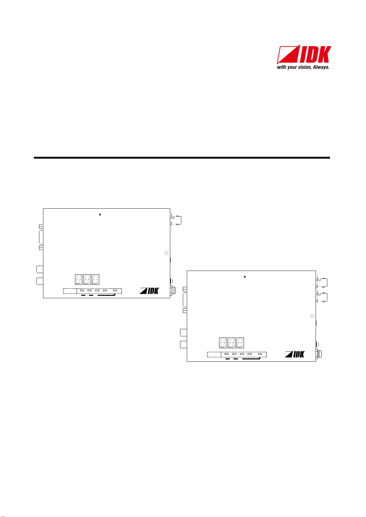
HDMI Coaxial Cable Extender
COS-100HD-B
Users Guide
Ver.1.5.0
● Thank you for choosing our product.
● To ensure the best performance of this product, please read this User’s Guide fully and carefully before
using it and keep this manual together with the product for reference as needed.
IDK Corporation

COS-100HD-B User’s Guide
Trademarks
Blu-ray Disc and Blu-ray are trademarks of Blu-ray Disc Association.
The terms HDMI and HDMI High-Definition Multimedia Interface, and the HDMI Logo are trademarks or
registered trademarks of HDMI Licensing Administrator, Inc. in the United States and other countries.
Connection Reset is a registered trademark of IDK Corporation in Japan.
All other company and product names mentioned in this manual are either registered trademarks or
trademarks of their respective owners. In this manual, the “®” or “™” marks may not be specified.
2

COS-100HD-B User’s Guide
Before reading this manual
● All rights reserved.
● Some of the contents in this user’s guide such as the appearance of diagrams, menu operations,
communication commands, and so on may differ between products depending on the specific version.
● This Users guide is subject to change without notice. You can download the latest version from IDK’s
website at: http://www.idkav.com
FCC STATEMENT
This equipment has been tested and found to comply with the limits for a Class A digital device, pursuant to
part 15 of the FCC Rules. These limits are designed to provide reasonable protection against harmful
interference when the equipment is operated in a commercial environment. This equipment generates, uses,
and can radiate radio frequency energy and, if not installed and used in accordance with the instruction
manual, may cause harmful interference to radio communications. Operation of this equipment in a residential
area is likely to cause harmful interference, in which case the user will be required to correct the interference
at their own expense.
CE MARKING
This equipment complies with the essential requirements of the relevant European health, safety and
environmental protection legislation.
WEEE MARKING
Waste Electrical and Electronic Equipment (WEEE), Directive 2002/96/EC
(This directive is only valid in the EU.)
This equipment complies with the WEEE Directive (2002/96/EC) marking requirement.
The left marking indicates that you must not discard this electrical/electronic equipment in
domestic household waste.
3
COS-100HD-B User’s Guide
Safety Instructions
Enforcement Symbol
Description
Indicates the presence of a hazard that may result in death or serious
personal injury if the warning is ignored or the product is handled
incorrectly.
Indicates the presence of a hazard that may cause minor personal
injury or property damage if the caution is ignored or the product is
handled incorrectly.
Symbol
Description
Example
Caution
This symbol is intended to alert the user. (Warning and caution)
Electrical
Hazard
Prohibited
This symbol is intended to prohibit the user from specified actions.
Do not
disassemble
Instruction
This symbol is intended to instruct the user.
Unplug
Caution
Warning
Read and understand all safety and operating instructions before using this product. Follow all instructions
and cautions as detailed in this document.
4
COS-100HD-B User’s Guide
Prohibited
Do not place the product in any unstable place.
Install the product in a horizontal and stable place. Otherwise, it may fall/turn over and lead to injury.
Do not place the product in any environment with vibration.
Otherwise, it may move/fall and lead to injury.
Keep out any foreign objects.
In order to avoid fire or electric shock, do not allow foreign objects, such as metal and paper, to enter the product
from the vent holes.
For power cable/ plug:
Do not scratch, heat, or modify, including lengthening them.
Do not pull, place heavy objects on them, or pinch them.
Do not bend, twist, or tie them together forcefully.
Misuse of the power cable and plug may cause fire or electric shock. If power cables/plugs become damaged,
contact your IDK representative.
Do not
disassemble
Do not repair, modify or disassemble.
Since the product includes circuitry that uses potentially lethal, high voltage levels, disassembly by unauthorized
personnel may lead to the risk of fire or electric shock. For internal inspection or repair, contact your IDK
representative.
Do not
touch
In the event of electrical storms, keep away from the main unit and cables such as
power cable and LAN cable.
Contact may cause electric shock
Instruction
For installation:
The product is intended to be installed by skilled technicians. For installation, please contact a system integrator or
IDK. Improper installation may lead to the risk of fire, electric shock, injury, or property damage.
Set the power plug in a convenient place to unplug easily.
Unobstructed access to the plug enables unplugging the product in case of any extraordinary failure, abnormal
situation or for easy disconnection during extended periods of non-use.
Insert the power plug into an appropriate outlet completely.
If the plug is partially inserted, arching may cause the connection to overheat, increasing the risk of electrical shock
or fire. Do not use a damaged plug or connect to a damaged outlet.
Clean the power plug regularly.
If the plug is covered in dust, it may increase the risk of firer.
Unplug
Unplug immediately if the product smokes, makes unusual noise, or produces a
burning odor.
If you continue to use the product under these conditions, it may cause electric shock or fire. After confirming that
the product stops smoking, contact your IDK representative.
Unplug immediately if the product falls and/or if the cabinet is damaged.
If you continue to use the product under these conditions, it may increase the risk of electrical shock or fire. For
maintenance and repair, contact your IDK representative.
Unplug immediately if water or other objects are directed inside.
If you continue to use the product under these conditions, it may increase the risk of electrical shock or fire. For
maintenance and repair, contact your IDK representative.
For connection
Instruction
Differences in ground potential among product population of interconnected products and other external devices
may increase the risk of electric shock to personnel or cause damage to the devices or cabling infrastructure. When
using cables to connect devices, including connection of long-distance transmission cables, unplug the power
cables of all interconnected devices.
Power may be restored after all signal/control cables are connected to each device.
Warning
5
COS-100HD-B User’s Guide
Prohibited
Do not place the product in any place where it will be subjected to high
temperatures.
If the product is subjected to direct sunlight or high temperatures while under operation, it may affect the
product’s performance and reliability and may increase the risk of fire.
Do not place the product in humid, oil smoke filled, or dusty place.
If the product is placed near humidifiers or in a dusty area, it may increase the risk of fire or electric shock.
Do not block the vent holes.
If ventilation slots are blocked, it may cause the product to overheat, affecting performance and reliability and
may increase the risk of fire.
Do not place or stack heavy objects on the product.
Failure to observe this precaution may result in damage to the product and other property and may lead to the
risk of personal injury.
Do not exceed ratings of outlet and wiring devices.
Exceeding the rating of an outlet may increase the risk of fire and electric shock.
Use only the supplied AC adapter and power cable.
Do not use the supplied AC adapter and power cable with other products.
If non-compliant adapter or power cables are used, it may increase the risk of fire or electrical shock. Always
use the supplied AC power connection cable for this product.
No wet hands
Do not plug or unplug with wet hands.
Failure to observe this precaution may increase the risk of electrical shock.
Instruction
Use and store the product within the specified temperature/humidity range.
If the product is used outside the specified range for temperature and humidity continuously, it may increase the
risk of fire or electric shock.
Turn off devices while making connections to another device.
Failure to observe this precaution may increase the risk of fire or electric shock.
Unplug
If the product won’t be used for an extended period of time, unplug it.
Failure to observe this precaution may increase the risk of fire.
Unplug the product before cleaning.
To prevent electric shock.
For installation
Instruction
Mount the product in a the rack meeting EIA standards, and maintain spaces above and
below for air circulation. For your safety, attach an L-shaped bracket in addition to the
panel mount bracket kit to improve mechanical stability.
Instruction
Never insert screws without the rubber feet into the threaded holes on the bottom of the
product. Doing so may lead to damage when the screws contact electrical circuitry or
components inside the product.
Reinstall the originally supplied rubber feet using only the originally supplied screws.
Instruction
Do not place the product at elevations of 2,000 meters (6562 feet) or higher above sea
level. Failure to do so may shorten the life of the internal parts and result in malfunctions.
Caution
For rack mount devices:
For devices with rubber feet:
Altitude:
6

COS-100HD-B User’s Guide
Table of Contents
1 Included Items ...................................................................................................................................... 9
2 Product Outline....................................................................................................................................10
3 Features ..............................................................................................................................................11
4 Panels .................................................................................................................................................12
4.1 Transmitter .....................................................................................................................................12
4.2 Receiver .........................................................................................................................................14
5 Connecting to external device ..............................................................................................................16
5.1 Preparation .....................................................................................................................................16
5.1.1 Coaxial cable ..........................................................................................................................16
5.1.2 RS-232C cable ........................................................................................................................17
5.2 Precautions ....................................................................................................................................17
5.3 Application example .......................................................................................................................20
5.4 Daisy Chain connection ..................................................................................................................21
6 Basic Operation ...................................................................................................................................22
6.1 Menu operation buttons ..................................................................................................................22
6.2 Locking menu operation buttons .....................................................................................................23
6.3 Initialization ....................................................................................................................................23
7 Menu ................................................................................................................................ ...................24
7.1 Menu List .......................................................................................................................................25
7.1.1 Transmitter ..............................................................................................................................25
7.1.2 Receiver..................................................................................................................................26
Displaying firmware version..................................................................................................................26
7.2 Transmitter (Setup menu) ...............................................................................................................28
7.2.1 [ F01 ] Copying EDID ..............................................................................................................28
7.2.2 [ F02 ] EDID resolution ............................................................................................................29
7.2.3 [ F03 ] No-signal input monitoring time.....................................................................................31
7.2.4 [ F04 ] PCM Audio ...................................................................................................................32
7.2.5 [ F05 ] AC-3 Dolby Digital Audio ..............................................................................................32
7.2.6 [ F06 ] AAC Audio ...................................................................................................................32
7.2.7 [ F07 ] Dolby Digital Plus Audio ...............................................................................................32
7.2.8 [ F08 ] DTS Audio ....................................................................................................................33
7.2.9 [ F09 ] Audio channel ..............................................................................................................33
7.2.10 [ F10 ] EDID WXGA.................................................................................................................34
7.2.11 [ F11 ] Analog / Digital audio ....................................................................................................34
7.2.12 [ F90 ] Displaying firmware version ..........................................................................................34
7.2.13 [ F91 ] Displaying hardware version .........................................................................................34
7.2.14 [ F99 ] Maintenance / Status display menu ..............................................................................34
7.3 Transmitter (Maintenance menu) ....................................................................................................35
7.3.1 [ C01 ] HDCP input setting ......................................................................................................35
7.3.2 [ C10 ] Test pattern resolution .................................................................................................36
7.3.3 [ C11 ] Test pattern output .......................................................................................................37
7.3.4 [ C12 ] Input status On-screen-display .....................................................................................38
7.3.5 [ C13 ] RS-232C communication mode ....................................................................................39
7.3.6 [ C14 ] RS-232C communication: Baud rate ............................................................................39
7.3.7 [ C15 ] RS-232C communication: Data bit length .....................................................................39
7.3.8 [ C16 ] RS-232C communication: Parity check .........................................................................39
7.3.9 [ C17 ] RS-232C communication: Stop bit ................................................................................40
7

COS-100HD-B User’s Guide
7.4 Transmitter (Displaying input status) ...............................................................................................41
7.4.1 [ L01 to L13 ] Displaying input information ...............................................................................41
7.5 Receiver (Setting menu) .................................................................................................................44
7.5.1 [ F01 ] Digital audio output .......................................................................................................44
7.5.2 [ F02 ] Analog audio output......................................................................................................44
7.5.3 [ F90 ] Displaying firmware version ..........................................................................................44
7.5.4 [ F91 ] Displaying hardware version .........................................................................................44
7.5.5 [ F99 ] Maintenance / Status display menu ..............................................................................44
7.6 Receiver (Maintenance menu) ........................................................................................................45
7.6.1 [ C01 ] Hot plug masking .........................................................................................................45
7.6.2 [ C02 ] Checking sink device EDID ................................ .......................................................... 45
7.6.3 [ C03 ] Output mode ................................................................................................ ................46
7.6.4 [ C10 ] Test pattern resolution .................................................................................................47
7.6.5 [ C11 ] Test pattern output .......................................................................................................48
7.6.6 [ C12 ] Output status On-screen-display ..................................................................................49
7.6.7 [ C13 ] RS-232C communication mode ....................................................................................50
7.6.8 [ C14 ] RS-232C communication: Baud rate ............................................................................50
7.6.9 [ C15 ] RS-232C communication: Data bit length .....................................................................50
7.6.10 [ C16 ] RS-232C communication: Parity check .........................................................................50
7.6.11 [ C17 ] RS-232C communication: Stop bit ................................................................ ................50
7.6.12 [ C18 ] RS-232C communication: Receiver ID .........................................................................51
7.7 Receiver (Displaying output status) .................................................................................................52
7.7.1 [ L01 to L07 ] Displaying output information .............................................................................52
8 Product specification ...........................................................................................................................54
8.1 Pin assignment ...............................................................................................................................54
8.1.1 HDMI TypeA connector ...........................................................................................................54
8.1.2 RS-232C connector .................................................................................................................54
8.2 Product specification.......................................................................................................................56
9 Troubleshooting...................................................................................................................................58
8
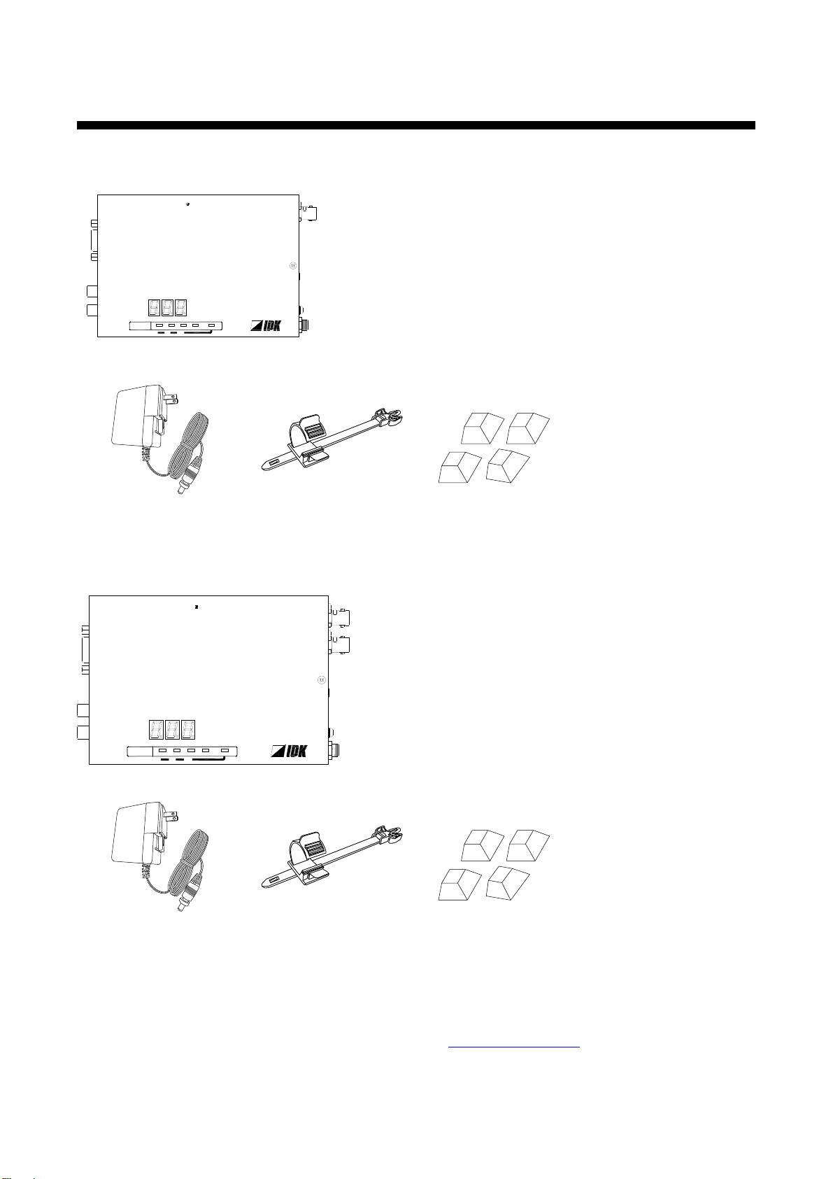
1 Included Items
COS-T100HD-B
One (1) AC adapter 5.9 ft.
(1.8 m) with locking
mechanism
One (1) cable clamp
Four (4) rubber feet
One (1) AC adapter 5.9 ft.
(1.8 m) with locking
mechanism
One (1) cable clamp
Four (4) rubber feet
RS-232C
L
AUDIO INPUT
R
Tx
1 COAX Tx for HDMI CO S-T100HD-B
FGDC 5V 3A
HDMI
OUTPUT
HDMI
INPUT
POWER
STATUS
LINK KEY LOCK
-+
SET
SIGNAL HDCP
RS-232C
FGDC 5V 3A
HDMI
Rx
COS-R100HD-B
L
AUDIO OUTPUT
R
POWER
STATUS
LINK KEY LOCK
-+
SET
SIGNAL HDCP
OUTPUTINPUT
1 COAX Rx for HDMI
OUTPUT
Ensure that all items illustrated below are included in the package.
If any items are missing or damaged, please contact IDK.
COS-100HD-B User’s Guide
COS-R100HD-B
You can download the latest version from IDK’s website at: http://www.idkav.com
[Fig. 1.1] Included items
9
COS-100HD-B User’s Guide
Coaxial
Transmission
Digital video/audio
HDMI
DVI
input
1
EDID emulation
Receiver
COS-T100HD-B
Up to 98ft. (30 m)
Up to 689 ft. (210 m)*
1
Analog audio
L/R unbalanced
iinput
1
A/D conversion
Coaxial
Transmission
COS-R100HD-B
D/A conversion
Audio
Audio
Daisy Chain
*1 When L-7CHD (Canare Electric Co., Ltd.) cable is used
Up to 16 ft. (5 m)
RS-232C
※
2
*2 Bidirectional communication between a specific receiver
Audio
Video
Digital video/audio
HDMI
DVI
Output
1
Analog audio
L/R unbalanced
Output
1
RS-232C*
2
Transmitter
Audio
Video
Up to 689 ft. (210 m)*
1
Coaxial
Transmission
COS-R100HD-B
D/A conversion
Audio
Up to 16 ft. (5 m)
Digital video/audio
HDMI
DVI
Output
1
Analog audio
L/R unbalanced
Output
1
RS-232C*
2
Transmitter
Audio
Video
Coaxial
Transmission
Digital video/audio
HDMI
DVI
input
1
EDID emulation
Receiver
COS-T100HD-B
Up to 98ft. (30 m)
Up to 689 ft. (210 m)*
1
Analog audio
L/R unbalanced
input
1
A/D conversion
Coaxial
Transmission
COS-R100HD-B
D/A conversion
Audio
Audio
Up to 16 ft. (5 m)
RS-232C
※
2
Audio
Video
Digital video/audio
HDMI
DVI
Output
1
Analog audio
L/R unbalanced
Output
1
RS-232C
Transmitter
Audio
Video
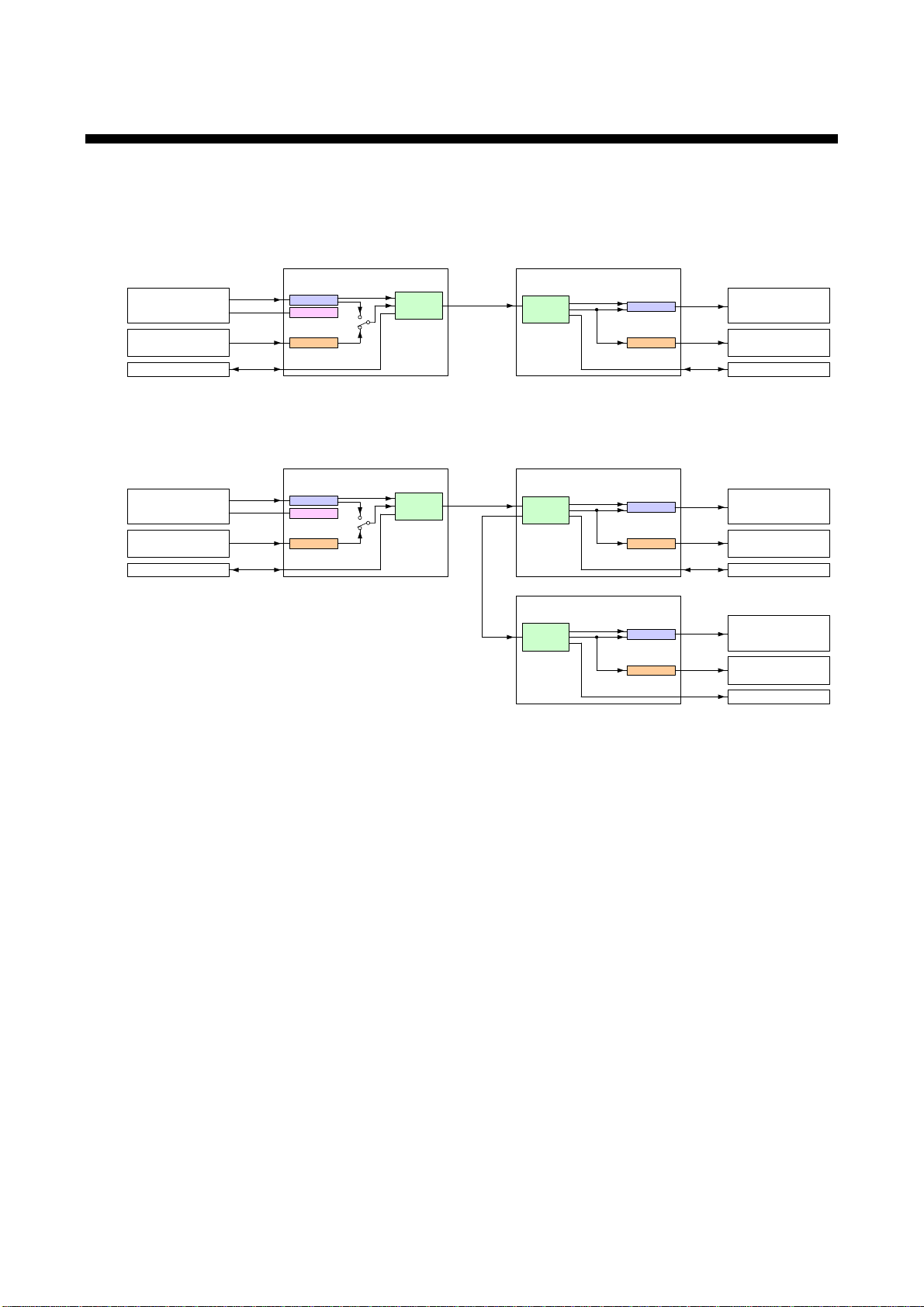
■One receiver is used
■Daisy chain connection
port
1
port
1
port
1
Port
1
Output
1
2 Product Outline
The COS-100HD-B is a transmitter and receiver set that enables HDMI signals to be transmitted over a
coaxial cable. It also supports Daisy Chain and RS-232C bidirectional communication.
Note:
The COS-T100HD (Transmitter) and COS-R100HD (Receiver) have to be used together.
IDK’s own format is employed for digital signal for extension between the transmitter and receiver. Any device
cannot be connected between the COS-T100HD and COS-R100HD.
10
[Fig. 2.1] COS-100HD-B Diagram

3 Features
■ Video
・Maximum resolution: QWXGA (Reduced Blanking),1080p
・HDCP
・Maximum extension distance: 361 ft. (110 m) over L-5CFB cable
・Daisy chain connection
・Anti-snow
■ Audio
・Embedding/De-embedding
■ Communication
・RS-232C bidirectional communication
・Simultaneous transmission to all receivers in Daisy Chain connection
・Bidirectional communication with a specific receiver
■ Others
・EDID emulation
・Connection Reset
・Built-in test patterns and test tones
・I/O signal status check (7 segment and OSD)
・HDMI and serial signals transmission over one single coaxial cable
・AC adapter with locking mechanism
COS-100HD-B User’s Guide
98 ft. (30 m) over HDMI cable connected to the transmitter
11
COS-100HD-B User’s Guide
①
②
⑨
⑧
③
④
⑥
⑩
⑤
⑦
⑪
RS-232C
L
AUDIO INPUT
R
Tx
1 COAX Tx for HDMI COS-T100HD-B
FGDC 5V 3A
HDMI
OUTPUT
HDMI
INPUT
POWER
STATUS
LINK KEY LOCK
-+
SET
SIGNAL HDCP
#
Feature
Description
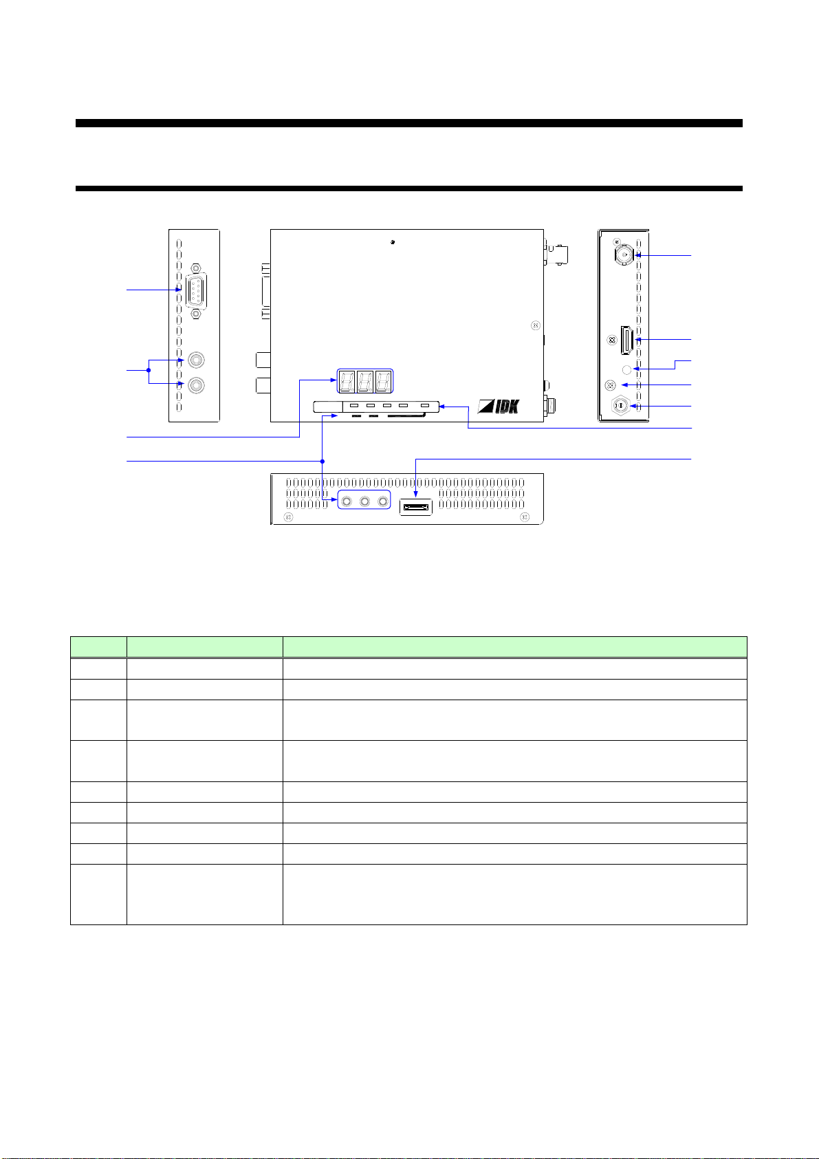
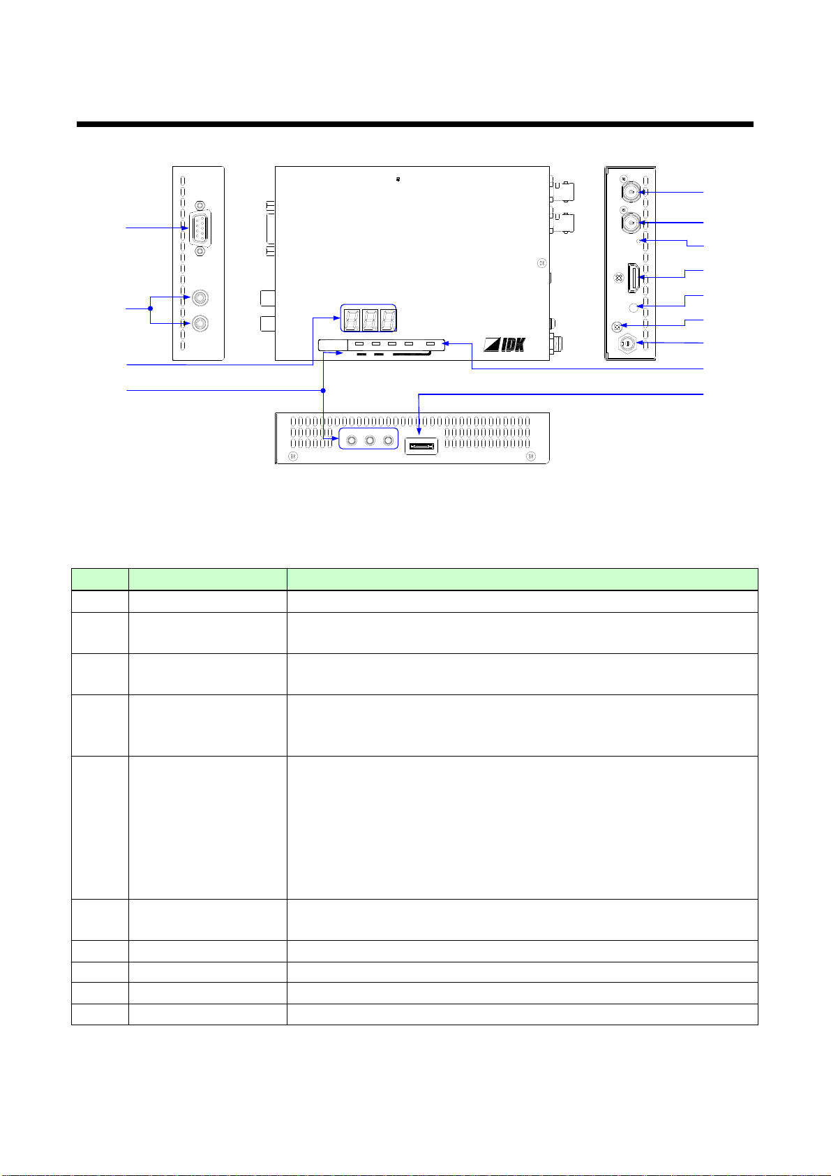
①
RS-232C connector
Connector for RS-232C signal. Connected to a control device (e.g. PC).
②
Audio input connectors
Input connector for analog audio input.
③
Output connector for
extension
Output connector for digital signals for extension. Connected to the
receiver using a coaxial cable.
④
HDMI input connector
Input connector for HDMI signals.
Connected to a source device (e.g. Blu-ray player).
⑤
HDMI cable fixing hole
Retains HDMI cables by inserting cable clamps.
⑥
Frame ground
Use for bonding chassis to local ground. An M3 screw is used.
⑦
Power connector
Connector for the included AC adapter.
⑧
7-segment display
Displays menu items and setting status.
⑨
Menu operation
buttons
Sets I/O settings of the transmitter and locks menu operation buttons
● Use “SET”, “+”, and “-” buttons to set I/O settings of the transmitter.
● Press and hold the “SET” button in order to lock those buttons.
4 Panels
4.1 Transmitter
[Fig. 4.1] Panel drawings
[Table 4.1] Panel features
12
[Table 4.2] Panel features (cont’d)
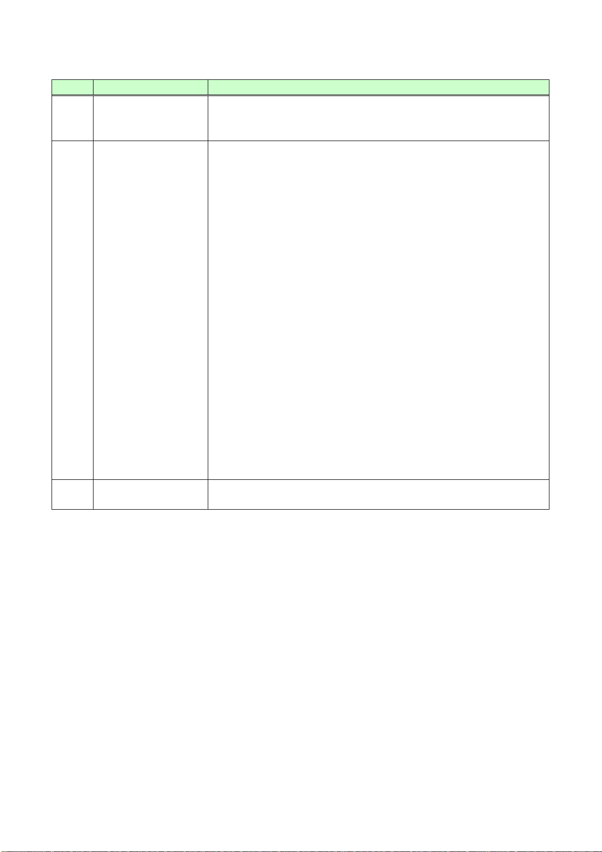
#
Feature
Description
⑩
Status LEDs
・POWER
Illuminates green : Power is supplied.
Does not illuminate : Power is not supplied.
・LINK
Illuminates green : Connected to the COS-R100HD and
signal is recognized.
Does not illuminate : Not connected to the COS-R100HD or
connected to a device other than the
COS-R100HD.
・SIGNAL
Illuminates green : Vertical synchronous signal is input from
the HDMI input connector.
Does not illuminate : Vertical synchronous signal is not input
from the HDMI input connector.
・HDCP
Illuminates green : The input signal is with HDCP.
Does not illuminate : The input signal is not with HDCP.
・KEY LOCK
Illuminates green : Buttons are locked.
Flashes green : Buttons are being locked (being set).
Does not illuminate : Buttons are not locked.
⑪
Connector for
maintenance
Do not use this connector.
COS-100HD-B User’s Guide
13
COS-100HD-B User’s Guide
①
③
⑥
⑧
⑦
⑨
⑫
⑬
②
④
⑪
⑩
⑤
RS-232C
FGDC 5V 3A
HDMI
Rx
COS-R100HD-B
L
AUDIO OUTPUT
R
POWER
STATUS
LINK KEY LOCK
-+
SET
SIGNAL HDCP
OUTPUTINPUT
1 COAX Rx for HDMI
OUTPUT
#
Feature
Description
①
RS-232C connector
Connector for RS-232C signal. Connected to a control device (e.g. PC).
②
Audio output
connectors
De-embeds HDMI input audio to analog audio. Connected to amplifiers,
speakers or mixers.
③
Output connector for
extension
Output connector for digital signal for extension. Connected to the next
receiver over a coaxial cable in Daisy Chain connection.
④
Input connector for
extension
Input connector for digital signal for extension. Connected to the
transmitter over a coaxial cable. Connected to the previous receiver in
Daisy Chain connection.
⑤
LED for detecting
abnormality in
transmission
Lights in green when valid code is transmitted (Tx) or received (Rx).
Illuminates green : Connected to a receiver over a coaxial
cable and recognizes signal.
Flashes green : Problems occurs in signal.
Flashes green : Signal cannot be recognized.
For extension distance, see [Table 5.1] Maximum extension
distance(P.16).
⑥
HDMI output connector
Output connector for HDMI signals.
Connected to a sink device (e.g. LC monitors).
⑦
HDMI cable fixing hole
Retains HDMI cables by inserting cable clamps.
⑧
Frame ground
Use for bonding chassis to local ground. An M3 screw is used.
⑨
Power connector
Connector for the included AC adapter.
⑩
7-segment display
Displays menu items and setting status.
4.2 Receiver
[Fig. 4.2] Panel drawings
[Table 4.3] Panel features
14
[Table 4.4] Panel features (cont’d)
#
Feature
Description
⑪
Menu operation
buttons
Sets I/O settings of the transmitter and locks menu operation buttons
● Use “SET”, “+”, and “-” buttons to set I/O settings of the transmitter.
● Press and hold the “SET” button in order to lock those buttons.
⑫
Status LEDs
・POWER
Illuminates green : Power is supplied.
Does not illuminate : Power is not supplied.
・LINK
Illuminates green : Connected to the COS-T100HD and
signal is recognized.
Does not illuminate : Not connected to the COS-T100HD or
connected to a device other than the
COS-T100HD.
・SIGNAL
Illuminates green : Vertical synchronous signal is input from
the transmitter.
Does not illuminate : Vertical synchronous signal is not input
from the transmitter.
・HDCP
Illuminates green : HDCP authentication completed.
Does not illuminate : The input signal is not with HDCP./
The sink device does not support HDCP./.
HDCP authentication failed.
・KEY LOCK
Illuminates green : Buttons are locked.
Flashes green : Setting is being changed.
Does not illuminate : Buttons are not locked.
⑬
Connector for
maintenance
Do not use this connector.
COS-100HD-B User’s Guide
15
COS-100HD-B User’s Guide
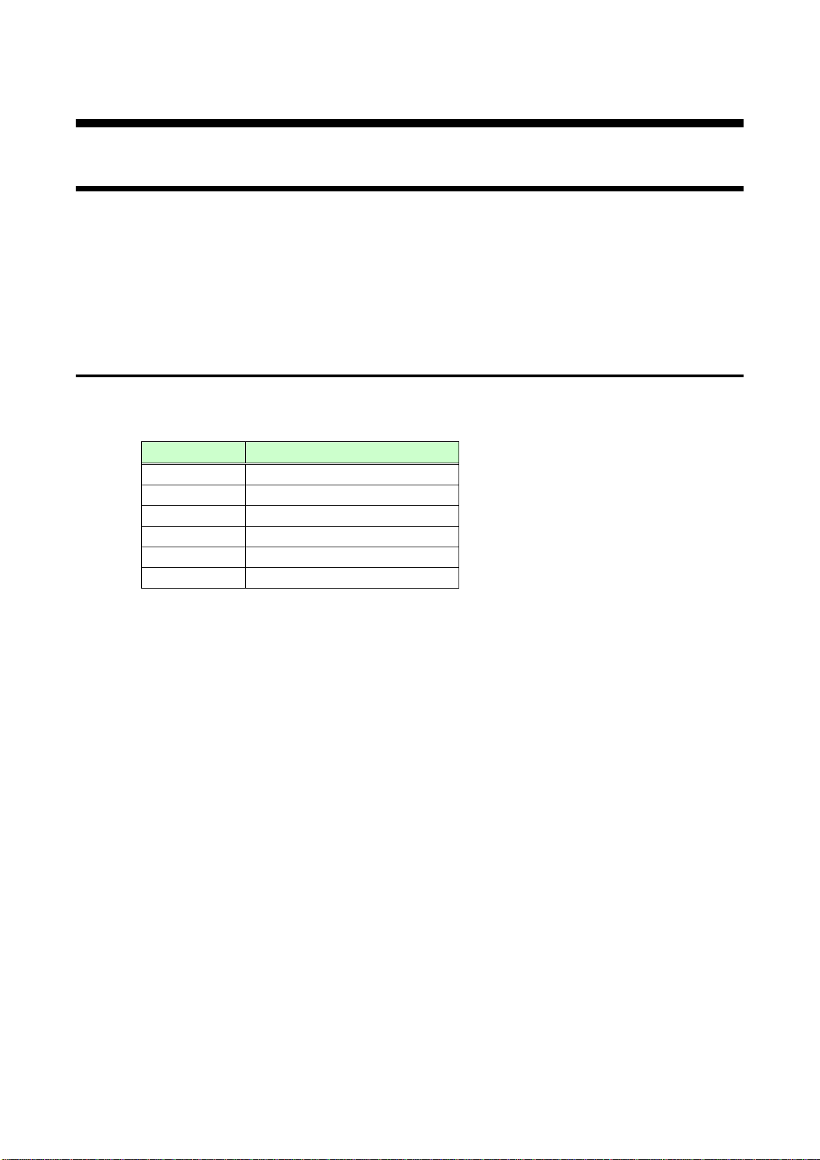
Cable type
Maximum extension distance
L-3C2V
131 ft. (40 m)
L-3CFB
262 ft. (80 m)
L-5C2V
197 ft. (60 m)
L-5CFB
361 ft. (110 m)
L-7CFB
492 ft. (150 m)
L-7CHD
689 ft. (210 m)
5 Connecting to external device
5.1 Preparation
Before connecting to external devices, such as source devices and sink devices, prepare the following cables:
● HDMI cable (19-pin TypeA)
● Coaxial cable (BNC connector)
● Stereo audio cable (RCA pin plug)
● RS-232C cable (D-sub9 pin, female)
5.1.1 Coaxial cable
Use appropriate coaxial cables.
[Table 5.1] Maximum extension distance
Notes:
Those distances were obtained under tests using Canare’s cable. If you use other manufactures’ cable or a
cable joint (JJ), the distances above are not guaranteed.
If Canare’s L-5CFB and BCJ-J (cable joint) are used together, up to 5 JJs can be used. The total extension
distance may be shortened if a JJ has a problem or impedance mismatch.
The extension distance may be shortened or the number of JJs may be reduced depending on characteristics
of source devices and source devices. The cable length needs to be long enough to avoid those problems.
16
COS-100HD-B User’s Guide
1.2 in. (30 mm) or more
Bad example
Good example
Good example
5.1.2 RS-232C cable
・RS-232C signal (up to 38400 bps) can be transmitted bi-directionally.
・Select cross cables or straight cable depending on devices to be connected.
【See:8.1.2 RS-232C (P.54) 】
5.2 Precautions
Before using the COS-100HD-B, follow the precautions and instructions below.
■ Attaching rubber feet
First, clean the bottom surface of the COS-100HD-B as needed, and then peal the release papers from the
rubber feet and place them in each of the four corners.
■ Installation
・ Before you connecting cables to the COS-100HD-B or an external device, dissipate static electricity
by touching grounded metal such as racks before handling signal cables. Failure to observe this
precaution may result in ESD (electrostatic discharge) damage.
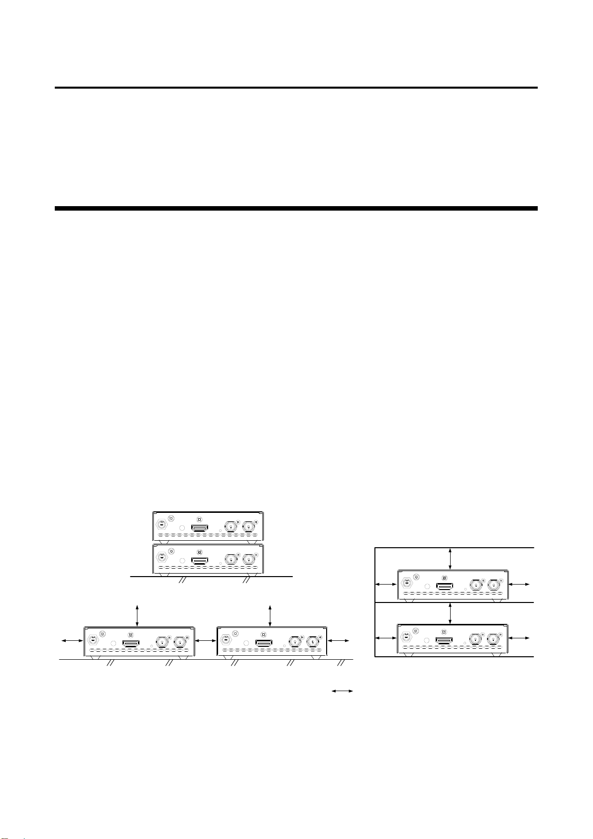
・ Do not place the COS-100HD-B on another device directly. The temperature of its bottom surface is
elevated after it is powered on.
・ Do not block vent holes. To provide adequate ventilation, maintain sufficient clearances around the
COS-100HD-B (1.18 in. (30 mm) or more).
・ Prepare ventilating equipment to keep the ambient temperature at 40 degrees C (104 degrees F) or
less. If inadequately vented, the life of parts may be shortened and operation may be affected.
・ When you do not use an EIA rack-mount unit, maintain adequate clearances 1.18 in. (30 mm) or
more) as shown below.
[Fig. 5.1] Minimum required clearances (when an EIA rack-mount unit is not used)
17
COS-100HD-B User’s Guide
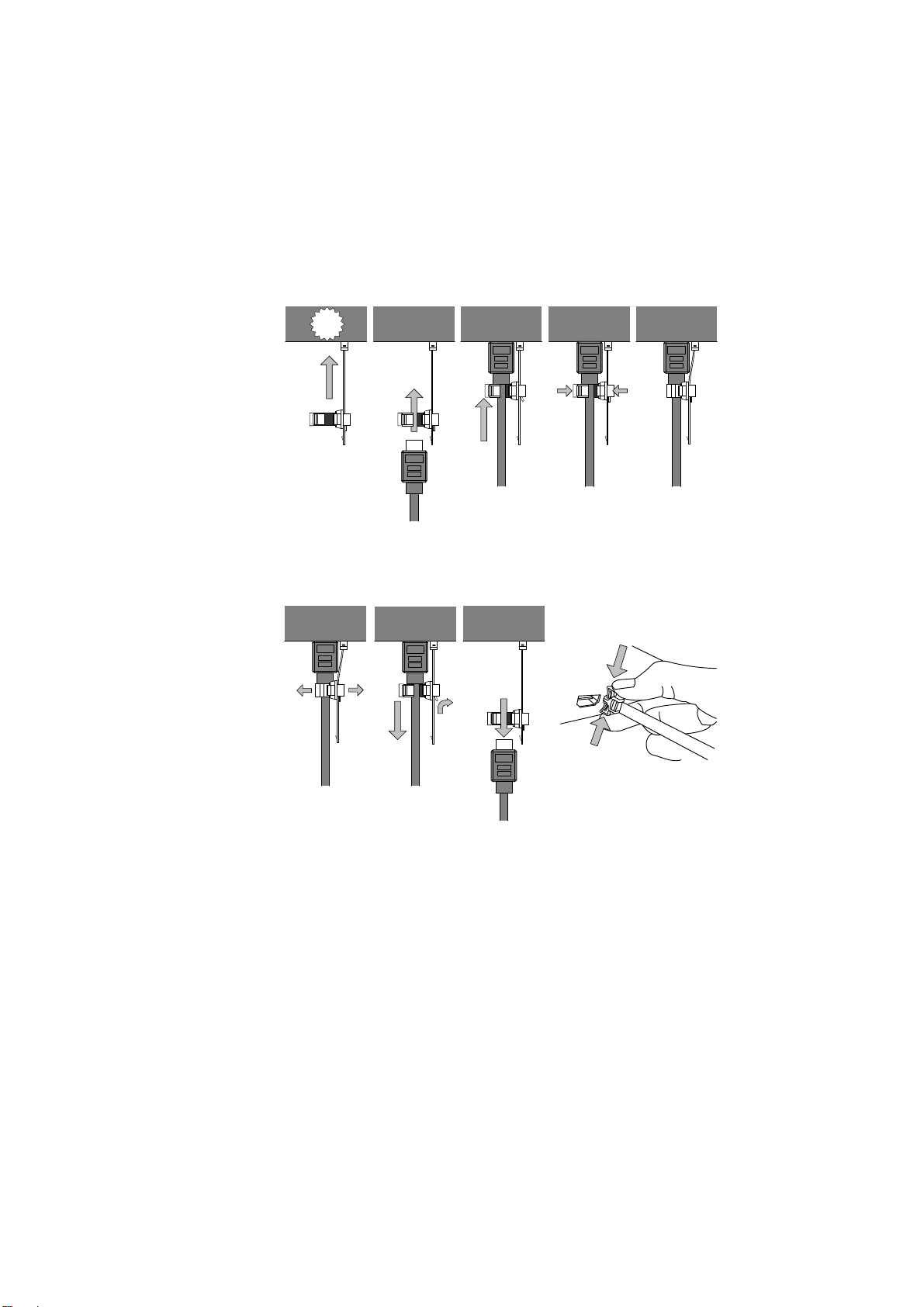
② ④ ⑤① ③
Click
Fixing HDMI cable using
cable clamp
①
②
③
Removing HDMI cable and cable
clamp
Pull out while
holding this portion
④
■ Cabling
Follow the precautions below when connecting the COS-100HD-B to target devices.
・Read the user’s guides of connected devices carefully.
・Power off all devices.
・Be sure to fully seat all plugs and connections and dress cables to reduce stress on connectors.
・Secure the HDMI cable using an attached cable clamp in order to prevent it from falling off this device.
[Fig. 5.2] Attaching and removing cable clamp
18
COS-100HD-B User’s Guide
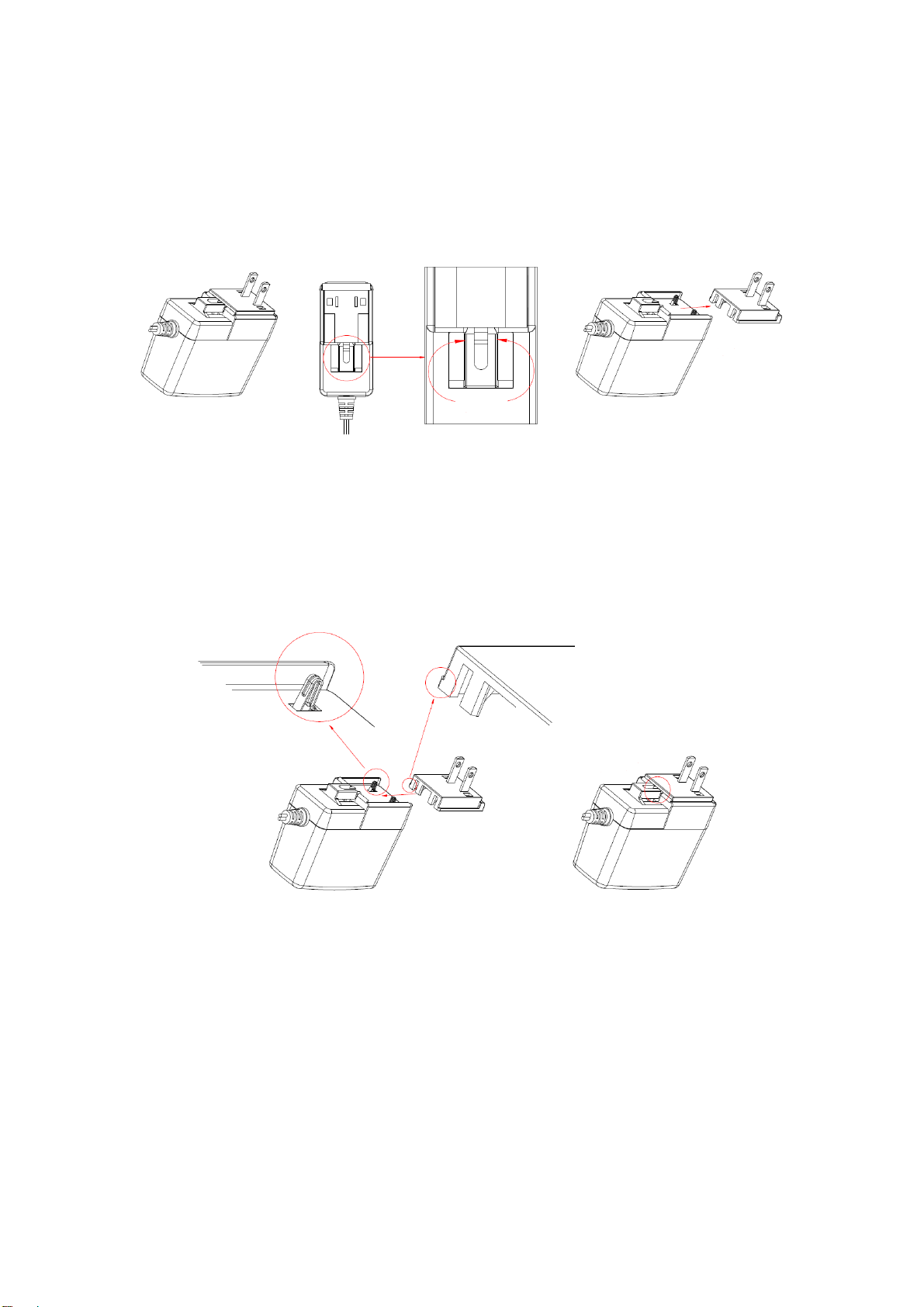
①
②
③
④
Bracket ear
■ AC adapter with locking mechanism
The shapes of AC plugs with screw lock mechanism vary from country to country. The AC plug can be
removed from the AC adapter.
Removing AC plug:
Slide the AC plug (②) from the AC adapter while holding down the portion mentioned below (①).
[Fig. 5.3] Removing AC plug (For Japan and U.S.A.)
Attaching AC plug:
Gently slide the AC plug into the AC adapter (③) until it clicks (④).
[Fig. 5.4] Attaching AC plug (For Japan and U.S.A.)
19
 Loading...