


VisionPass
Installation guide
Copyright 2019 Idemia
October 2019 | 2019_2000045728

Copyright 2019 Idemia
October 2019 | 2019_2000045728

Warning
COPYRIGHT © 2019 Idemia. All rights reserved.
Reproduction in whole or in part in any form or medium without the express written permission of Idemia is prohibited. The trademarks identified herein are the trademarks of registered trademarks of Idemia, or other third party.
This legend is applicable to all pages of this document.
Information in this document is subject to change without notice and do not represent a commitment on the part of Idemia.
This manual makes reference to names and products that are trademarks of their respective owners.
3 |
VisionPass - 2019_2000045728 |

Revision history
Version |
Date |
Reference |
Description |
01 |
October |
2019_2000045728 |
Document creation |
|
2019 |
|
|
4 |
VisionPass - 2019_2000045728 |

Table of content
1 / Introduction |
8 |
|
1.1 |
> VisionPass terminal |
9 |
1.2 |
> Scope of the document |
10 |
1.3 |
> Safety Instructions |
11 |
1.4 |
> Wiring Recommendations |
12 |
1.5 |
> Regulatory, safety and Environmental notices |
13 |
|
1.5.1 > European Union (CE) regulatory notices |
13 |
|
1.5.2 > USA (FCC) regulatory notices |
14 |
|
1.5.3 > Canada (IC) regulatory notices |
15 |
1.6 |
> Others recommendations |
17 |
1.7 |
> Recommendations for terminal implementation |
18 |
2 / General description |
21 |
|
2.1 |
> Box opening |
22 |
2.2 |
> Components of the initial package |
23 |
2.3 |
> Terminal's front view description |
24 |
2.4 |
> Terminal's rear view description |
25 |
2.5 |
> VisionPass Technical Characteristics |
26 |
3 / Installation procedure |
29 |
|
3.1 |
> Before proceeding to the installation |
30 |
3.2 |
> Installation |
31 |
3.3 |
> Step by step procedure |
32 |
|
3.3.1 > Drill the mounting holes |
33 |
|
3.3.2 > Make the connections |
34 |
|
3.3.3 > Attach the base plate on the wall |
37 |
|
3.3.4 > Attach the device on the base plate |
38 |
|
3.3.5 > Connect the connector assembly on the device |
39 |
|
3.3.6 > Close the device on the base plate |
40 |
4 / Electrical interface |
43 |
|
4.1 |
> Wiring overview |
44 |
4.2 |
> Power Supply |
45 |
5 |
|
VisionPass - 2019_2000045728 |

4.3 |
> Output Relay |
46 |
|
4.4 |
> Tamper Switch |
47 |
|
4.5 |
> Wiegand wiring |
48 |
|
4.6 |
> Wiegand output |
49 |
|
4.7 |
> Serial port wiring |
51 |
|
4.8 |
> GPIO wiring |
53 |
|
4.9 |
> Ethernet connection |
54 |
|
4.10 |
> Internal USB connection |
55 |
|
4.11 |
> Wi-Fi™ dongle installation |
57 |
|
5 / User interface |
59 |
5.1 > Modes for controlling access rights |
60 |
5.1.1 > Introduction |
60 |
5.1.2 > Identification mode |
60 |
5.1.3 > Authentication (verification) mode |
60 |
5.1.4 > Multi-factor mode |
61 |
5.1.5 > Proxy mode |
61 |
5.1.6 > External database mode (also called polling mode) |
62 |
5.1.7 > Anti-tamper / anti-pulling switches |
62 |
6 |
/ Accessories, Software Licenses and PC Applications |
63 |
|
6.1 |
> Compatible Accessories, Licenses and Software |
64 |
|
6.2 |
> Compatible PC applications |
65 |
|
7 |
/ Recommendations |
66 |
|
8 |
/ Annex 1 : finger placement recommendations |
69 |
|
8.1 |
> Main principles |
70 |
|
8.2 |
> Capture recommendations |
71 |
|
|
|
8.2.1 > Proper Use |
71 |
|
|
8.2.2 > Improper Use |
72 |
9 |
/ Annex 2 : Bibliography |
73 |
|
9.1 |
> How to get the latest versions of documents |
74 |
|
9.2 |
> Documents about the MorphoWave Compact terminal |
75 |
|
10 / Annex 3 : Support |
76 |
||
10.1 > Troubleshooting |
77 |
||
10.2 > Technical Support and Hotline |
77 |
||
6 |
VisionPass - 2019_2000045728 |

7 |
VisionPass - 2019_2000045728 |

1 / Introduction
8 |
VisionPass - 2019_2000045728 |

1.1 > VisionPass terminal
Congratulations for choosing VisionPass Automatic Face Recognition Terminal!
VisionPass provides an innovative and effective solution for access control applications using very fast acquisition of the face.
Among a range of alternative biometric technologies, the use of face has significant advantages: very fast acquisition just facing the terminal, and no physical contact between the applicant and the terminal.
VisionPass integrates Idemia image processing and feature matching algorithms. This technology is based on lessons learned during 25 years of experience in the field of biometric identification.
We believe you will find the VisionPass fast, accurate, easy to use and suitable for physical access control. The VisionPass offers the following advantages:
High quality optical sensor with anti-spoofing option,
Supports multiple input/output interfaces used in the physical access control industry,
Local Area Network interface for easy interaction with other host systems; LAN and WLAN possibilities (Wi-Fi™ as an option),
Intuitive man machine interface with touch panel and display, that is easy to use in both setup and operational modes,
Sturdy wall mounting with easy holding of product during cabling or maintenance.
To ensure the most effective use of your VisionPass terminal, we recommend that you read this Installation Guide completely.
9 |
VisionPass - 2019_2000045728 |

1.2 > Scope of the document
This guide deals with the installation of VisionPass, which is made up of the following list of products:
|
|
Contactless smartcard reader |
|
Regulatory |
||
VisionPass Marketing Name |
|
|
|
|
Water |
|
Biometrics |
|
MIFARE® |
|
Model Number |
||
|
|
Resistant |
||||
|
|
iCLASS® DESFire® |
Prox® |
(*) |
||
|
|
|
NFC |
|
|
|
VisionPass MD |
|
|
|
|
|
MPH-AC006A |
VisionPass MDPI |
|
|
|
|
|
MPH-AC006B |
(*) The Regulatory Model Number is the main product identifier in the regulatory documentation and test reports associated to the product
10 |
VisionPass - 2019_2000045728 |
1.3 > Safety Instructions
 means Direct Current (DC)
The installation of this product should be made by a qualified service Person and should comply with all local regulations.
It is strongly recommended to use a class II power supply at 12V-24V and 3 A min (at 12V) in conformity with Safety Electrical Low Voltage (SELV). The power supply cable length should not exceed 10 meters.
This system must be installed in accordance with the National Electrical Code (NFPA 70), and the local authority having jurisdiction.
This product is intended to be installed with a power supply complying with IEC60950-1, in accordance with the NEC Class 2 requirements; or supplied by a listed IEC60950-1 external Power Unit marked Class 2, Limited Power source, or LPS and rated 12VDC, 3 A minimum or 24VDC, 1.5 A minimum.
Note that all connections of the VisionPass terminal described hereafter are of SELV (Safety Electrical Low Voltage) type.
11 |
VisionPass - 2019_2000045728 |
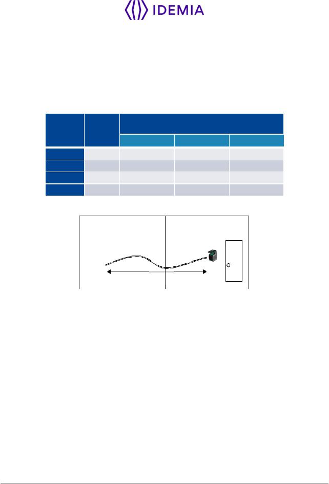
1.4 > Wiring Recommendations
Idemia recommends using a AWG16 gauge and 24V power supply.
The voltage specified is the one measured on the product block connector: 12V-24V (-15% / +10%).
The voltage drop due to the cable shall be taken into account. The following table shows the maximum distance between power supply and one (1) unique device, depending on cable gauge and power supply rating:
Gauge |
Section |
AWG |
(mm2) |
16 |
1.31 |
18 |
0.82 |
20 |
0.52 |
22 |
0.32 |
Maximum distance (meters) vs power source rating
12V+/-10% |
12V+/-5% |
24V+/-10% |
9 m |
20 m |
300 m |
6 m |
12 m |
200 m |
3 m |
8 m |
120 m |
2 m |
5 m |
75 m |
V1 |
V2 |
|
L
Figure: Power supply voltage dropout considerations
Drop voltage = loss of power due to wire resistance and its length: V2 = V1 – Drop voltage
12 |
VisionPass - 2019_2000045728 |

1.5 > Regulatory, safety and Environmental notices
1.5.1 > European Union (CE) regulatory notices
Declaration of Conformity
Products bearing the CE marking comply with one or more of the following EU Directives as may be applicable:
Radio Equipment Directive (RED) 2014/53/UE Ecodesign Directive 2009/125/EC
RoHS Directive 2011/65/EU.
Compliance with these directives is assessed using applicable European Harmonised Standards. VisionPass terminals are intended to be used for professional application only (buildings, airport...).
The full Declaration of Conformity is available on demand to your reseller. Please, provide him the product model name or its Regulatory Model Number (Model on the label).
Products with wireless features (EMF)
This product meets the provisions of the EU's Council recommendation 1999/519/EC on the limitation of the exposure of the general public to electromagnetic fields (0 Hz to 300 GHz).
13 |
VisionPass - 2019_2000045728 |

1.5.2 > USA (FCC) regulatory notices
This device complies with part 15 of the FCC Rules. Operation is subject to the following two conditions: (1) this device may not cause harmful interference, and (2) this device must accept any interference received, including interference that may cause undesired operation.
This device complies with FCC radiation exposure limits set forth for general population (uncontrolled exposure). This device must not be collocated or operating in conjunction with any other antenna or transmitter.
Changes or modifications not expressly approved by the party responsible for compliance could void the user's authority to operate the equipment.
Responsible Party:
Idemia Identity & Security FRance 2 place Samuel de Champlain 92400 Courbevoie – France
NOTA : This equipment has been tested and found to comply with the limits for a Class B digital device, pursuant to Part 15 of the FCC Rules. These limits are designed to provide reasonable protection against harmful interference in a residential installation. This equipment generates, uses and can radiate radio frequency energy and, if not installed and used in accordance with the instructions, may cause harmful interference to radio communications. However, there is no guarantee that interference will not occur in a particular installation. If this equipment does cause harmful interference to radio or television reception, which can be determined by turning the equipment off and on, the user is encouraged to try to correct the interference by one of the following measures:
Reorient or relocate the receiving antenna.
Increase the separation between the equipment and receiver.
Connect the equipment into an outlet on a circuit different from that to which the receiver is connected. Consult the dealer or an experienced radio/TV technician for help.
Shielded cables must be used with this unit to ensure compliance with category B FCC restrictions. MPH-AC006B product model includes a module tested under the FCC rules for a Modular Approval.
FCCID: JQ6-SE3210
14 |
VisionPass - 2019_2000045728 |

1.5.3 > Canada (IC) regulatory notices
WARNING TO USERS IN THE CANADA / ATTENTION POUR LES UTILISATEURS AU CANADA
This device complies with Industry Canada license-exempt RSS standard(s). Operation is subject to the following two conditions: (1) this device may not cause interference, and (2) this device must accept any interference, including interference that may cause undesired operation of the device.
Under Industry Canada regulations, this radio transmitter may only operate using an antenna of a type and maximum (or lesser) gain approved for the transmitter by Industry Canada.
To reduce potential radio interference to other users, the antenna type and its gain should be so chosen that the equivalent isotropically radiated power (e.i.r.p.) is not more than that necessary for successful communication.
This device complies with IC radiation exposure limits set forth for general population (uncontrolled exposure). This device must not be collocated or operating in conjunction with any other antenna or transmitter.
Note : UL LLC has not verified this product for compliance in respect to Canadian standards.
MPH-AC006B product model includes a module compliant with limits set by Industry Canada
oIC: 2236B-SE3210
This device complies with Industry Canada's RNCs for unlicensed radio devices. Exploitation is permitted under the following two conditions:
1)The device must not cause interference.
2)The user of the device must accept any radio interference, even if the interference may compromise its operation.
In accordance with Industry Canada regulations, this radio transmitter may operate with a specific antenna and maximum gain (or lower) approved for the transmitter by Industry Canada. In order to reduce the risk of radio interference for other users, The type of antenna and its gain must be chosen so that the equivalent radiated isotropic power (p.i.r.e.) does not exceed the intensity necessary to establish satisfactory communication.
MPH-AC006B product model incorporates a module that meets Industry Canada's requirement set limits.
oIC: JQ6-SE3210
15 |
VisionPass - 2019_2000045728 |

ATTENTION POUR LES UTILISATEURS AU CANADA
Cet appareil est conforme aux normes RSS exemptes de licence d'Industrie Canada. Son fonctionnement est soumis aux deux conditions suivantes:
(1)cet appareil ne doit pas provoquer d'interférences, et
(2)cet appareil doit accepter toute interférence, y compris les interférences pouvant entraîner un fonctionnement indésirable de l'appareil.
Conformément aux réglementations d'Industry Canada, les émetteurs radio de cet appareil ne
peuvent fonctionner qu'à l'aide d'une antenne dont le type et le gain maximal (ou minimal) pour
ces émetteurs - transmetteurs sont approuvés par Industry Canada. Pour réduire le risque
d'interférence éventuelle pour les autres utilisateurs, le type et le gain de l'antenne doivent être
choisis de manière à ce que la puissance isotrope rayonnée équivalente (p.i.r.e.) minimale
nécessaire à une bonne communication soit fournie.
Cet appareil est conforme aux limites d'exposition aux rayonnements IC établies pour la population générale (exposition non contrôlée). Cet appareil ne doit pas être colocalisé ou fonctionner en conjonction avec une autre antenne ou un autre émetteur.
Remarque: UL LLC n'a pas vérifié la conformité de ce produit aux normes canadiennes.
Le modèle de produit MPH-AC006B comprend un module conforme aux limites établies par Industrie Canada
o IC: 2236B-SE3210
16 |
VisionPass - 2019_2000045728 |

1.6 > Others recommendations
Potential safety conditions notice
If you notice any of the following conditions (or if you have other safety concerns), do not use the product: crackling, hissing, or popping sound, or a strong odor or smoke coming from the product. It is normal for these conditions to appear when an internal electronic component fails in a safe and controlled manner. However, these conditions may also indicate a potential safety issue. Do not assume it is a safe failure. Turn off the product, disconnect it from its power source, and contact technical support for assistance.
Disposal of waste equipment by users
This symbol means do not dispose of your product with your other household waste. Instead, you should protect human health and the environment by handing over your waste equipment to a designated collection point for the recycling of waste electrical and electronic equipment.
17 |
VisionPass - 2019_2000045728 |

1.7 > Recommendations for terminal implementation
Every installation is unique. Sometimes the issues are well defined and can be handled in a standard fashion; sometimes the issues are very specific and may not be immediately recognizable.
Idemia recommends following these steps for a successful installation:
Plan the installation - Choose the type of hardware required, decide if a network is required, and decide on the location and number of required terminals.
Unpack all items - Unpack all items and check against the packing list.
Install network hardware components - Install the cabling and components needed to run the system.
Install software - Install the software needed to set up the terminals.
Pre-configure device - Connect the terminals to the Ethernet, supply power to the terminals, and preconfigure the terminals.
Mount devices - Mount the terminals in their final locations
Power distribution and device hook up - Connect the terminals wiring via the back panel.
Power-up procedure - Check the power connections, and then start the system safely. First Boot Assistant screen is displayed, where you can perform fundamental configuration.
18 |
VisionPass - 2019_2000045728 |
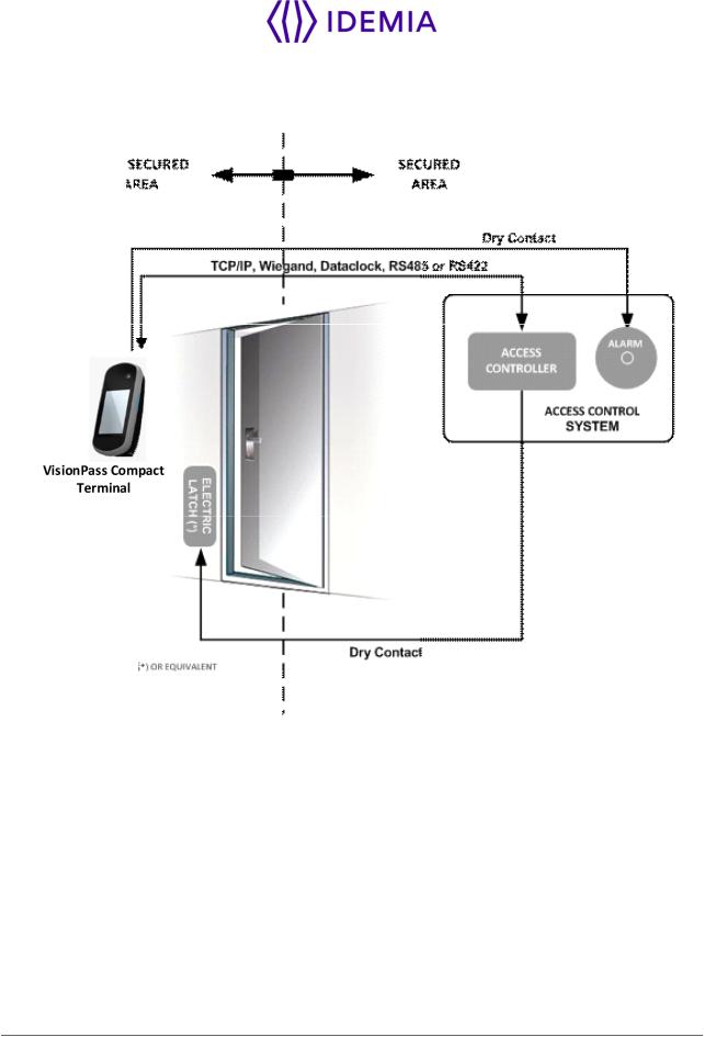
To secure properly an access, Idemia recommends installing the VisionPass terminal as a part of the typical Access Control environment described in the figure below.
Figure: Implementation Recommendations
This environment comprises:
The VisionPass terminal itself
Its role is to perform one-to-many biometric identification or one-to-one biometric verification, i.e. to identify the individual who is presenting his face by comparing his biometric data with the references previously stored in the terminal database (in the form of biometric templates) or to verify his identity using the reference stored in a contactless card presented to the terminal.
An Access Controller (3rd party product)
The Controller is the element which controls the access rights of the individuals to the secured area. For that reason, it must be located in the secured area.
The individuals who are authorized to access the secured area have their User ID listed in a so-called "Authorized User List" (in contrast with a banned card list).
19 |
VisionPass - 2019_2000045728 |

The VisionPass terminal and the Controller are communicating according to one of the TCP/IP, Wiegand, Dataclock or RS485 protocols:
The VisionPass terminal sends User ID to the Controller
The Controller sends its decision to the VisionPass terminal (which displays access granted or access denied depending on the answer)
The VisionPass terminal sends an alarm signal to the Controller as soon as a malicious operation is detected (terminal pulled out from the wall or opened for maintenance operations); refer the paragraph dealing with anti-pulling and anti-tamper switches for more explanations.
The Controller is part of the global Access Control System of the secured area, which can provide useful features such as manage:
Authorized user lists (i.e. for VIP), Banned card lists (i.e. for lost user cards),
An access request log (who and when, access granted or denied,..),
An event log (i.e. tamper detection, access control for evacuation of the building,...).
The VisionPass terminal is able to work alone, without Controller, but the protection level of the secured area is lower.
An Alarm (3rd party product)
This element is connected to the VisionPass terminal through a dry contact.
The VisionPass terminal sends the command to activate the Alarm as soon as a malicious operation (terminal pulled out from the wall or having its bottom cover opened out of maintenance operations) is detected; refer the paragraph dealing with anti-pulling and anti-tamper switches for more explanations.
A Door Electric Latch or equivalent (3rd party product)
This element once activated opens the access. The Controller is the one which sends the command to activate the latch if access is granted (i.e. if the individual's User ID is listed in the Controller Authorized User List). Connection between these two elements is done through a dry contact.
20 |
VisionPass - 2019_2000045728 |
2 / General description
21 |
VisionPass - 2019_2000045728 |

2.1 > Box opening
At the box opening, components shall be extracted from the protection casing as depicted in the pictures below.
Extract the wall plate (which is not screwed to the terminal) and keep it separate until the installation of the terminal is completed. The screwing of the product to the wall plate is the last stage of the installation.
Figure 1: Box Opening
22 |
VisionPass - 2019_2000045728 |
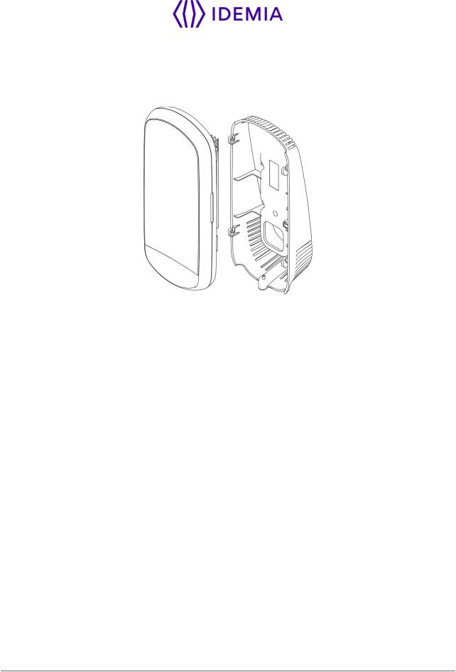
2.2 > Components of the initial package
Figure 2: Box Content
1.One (1) Terminal’s body
2.One (1) Wall frame
23 |
VisionPass - 2019_2000045728 |
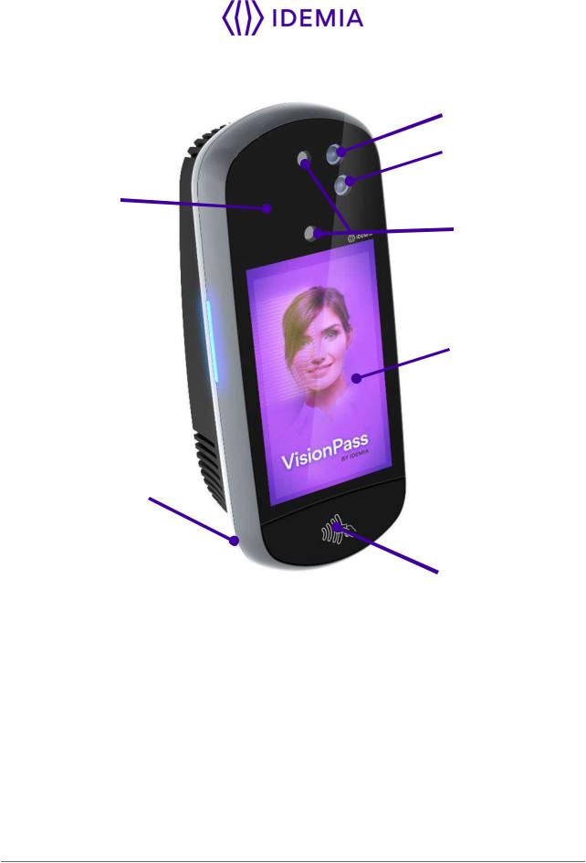
2.3 > Terminal's front view description
IR light
LED (power-on) 
microphone
NIR camera
Visible camera
3D cameras
7’’ WVGA touchscreen LCD
 speaker
contactless area
Figure 3: VisionPass terminal front view
24 |
VisionPass - 2019_2000045728 |
 Loading...