

Page 1

FC9Y-B644-04
FC4A SERIES
Micro Programmable
Logic Controller
FC4A-AS62M
AS-Interface Master Module
User’s Manual
Page 2
Warning
Warning notices are used to emphasize that improper operation may cause
severe personal injury or death.
Caution
Caution notices are used where inattention might cause personal injury or
damage to equipment.
SAFETY PRECAUTIONS
• Read this user’s manual to make sure of correct operation before starting installation, wiring, operation, maintenance, and
inspection of the MicroSmart AS-Interface master module.
• All MicroSmart AS-Interface master modules are manufactured under IDEC’s rigorous quality control system, but users
must add a backup or failsafe provision to the control system using the MicroSmart AS-Interface master module in applications where heavy damage or personal injury may be caused in case the MicroSmart AS-Interface master module should
fail.
• In this user’s manual, safety precautions are categorized in order of importance to Warning and Caution:
• Turn off the power to the MicroSmart before starting installation, removal, wiring, maintenance, and inspection of the
MicroSmart AS-Interface master module. Failure to turn power off may cause electrical shocks or fire hazard.
• Special expertise is required to install, wire, program, and operate the MicroSmart AS-Interface master module. People
without such expertise must not use the MicroSmart AS-Interface master module.
• Emergency stop and interlocking circuits must be configured outside the MicroSmart. If such a circuit is configured inside
the MicroSmart, failure of the MicroSmart may cause disorder of the control system, damage, or accidents.
• Install the MicroSmart AS-Interface master module according to the instructions described in this user’ s manual. Improper
installation will result in falling, failure, or malfunction of the MicroSmart AS-Interface master module.
• The MicroSmart AS-Interface master module is designed for installation in a cabinet. Do not install the MicroSmart AS-
Interface master module outside a cabinet.
• Install the MicroSmart AS-Interface master module in environments described in this user’s manual. If the MicroSmart
AS-Interface master module is used in places where the MicroSmart AS-Interface master module is subjected to high-temperature, high-humidity, condensation, corrosive gases, excessive vibrations, and excessive shocks, then electrical shocks,
fire hazard, or malfunction will result.
• The environment for using the MicroSmart AS-Interface master module is “Pollution degree 2.” Use the MicroSmart AS-
Interface master module in environments of pollution degree 2 (according to IEC 60664-1).
• Prevent the MicroSmart AS-Interface master module from falling while moving or transporting the MicroSmart AS-Inter-
face master module, otherwise damage or malfunction of the
• Prevent metal fragments and pieces of wire from dropping inside the MicroSmart AS-Interface master module housing.
Put a cover on the
chips may cause fire hazard, damage, or malfunction.
• Use a power supply of the rated value. Use of a wrong power supply may cause fire hazard.
• Use an IEC 60127-approved fuse on the power line outside the MicroSmart. This is required when equipment containing
MicroSmart is destined for Europe.
the
• Use an IEC 60127-approved fuse on the output circuit. This is required when equipment containing the MicroSmart is destined for Europe.
• Use an EU-approved circuit breaker. This is required when equipment containing the MicroSmart is destined for Europe.
• Make sure of safety before starting and stopping the MicroSmart or when operating the MicroSmart to force outputs on or
off. Incorrect operation on the MicroSmart may cause machine damage or accidents.
• Do not connect the ground wire directly to the MicroSmart. Connect a protective ground to the cabinet containing the
MicroSmart using an M4 or larger screw. This is required when equipment containing the MicroSmart is destined for
Europe.
• Do not disassemble, repair, or modify the MicroSmart modules.
• When disposing of the MicroSmart modules, do so as an industrial waste.
MicroSmart AS-Interface master module during installation and wiring. Ingress of such fragments and
MicroSmart AS-Interface master module will result.
MICROSMART AS-INTERFACE MASTER MODULE USER’S MANUAL PREFACE-1
Page 3

About This Manual
This user’s manual describes brief information about the AS-Interface and the entire functions, installation, and programming of the MicroSmart AS-Interface interface module.
Note: WindLDR Ver. 4.21 and higher are compatible with the AS-Inter face master module. This manual describes procedures
for using WindLDR Ver. 4.30.
CHAPTER 1: AS-INTERFACE
General information about of the Actuator-Sensor-Interface, abbreviated AS-Interface.
CHAPTER 2: MODULE SPECIFICATIONS
Specifications of the AS-Interface master module and applicable cables.
CHAPTER 3: INSTALLATION AND WIRING
Methods and precautions for installing and wiring the AS-Interface master module.
CHAPTER 4: OPERATION BASICS
General information about simple operating procedures for the basic AS-Interface system from programming WindLDR on
a computer to monitoring the slave operation.
CHAPTER 5: PUSHBUTTONS AND LED INDICATORS
Operation of pushbuttons PB1 and PB2 on the AS-Interface master module to change operation modes, and also the functions of address and I/O LED indicators.
CHAPTER 6: AS-INTERFACE OPERANDS
AS-Interface operands, or internal relays M1300 through M1997 and data registers D1700 through D1999, assigned in the
CPU module to control and monitor the AS-Interface bus. Provides detailed description about internal relays allocated to
SwitchNet™ control units for use as slaves in the AS-Interface network. Also describes ASI commands used to update ASInterface operands in the CPU module or to control the AS-Interface master module.
CHAPTER 7: USING WINDLDR
Procedures to use WindLDR ver. 4.30 for the AS-Interface system.
INDEX
Alphabetical listing of key words.
TM
SwitchNet is an IDEC trademark for pushbuttons, pilot lights, and other control units
capable of direct connection to the AS-Interface. SwitchNet devices are completely
compatible with AS-Interface Ver. 2.1.
Note: In this manual, “ASI” is shor t for “AS-Inter face” and is not intended to represent any par ticular product.
IMPORTANT INFORMATION
Under no circumstances shall IDEC IZUMI Corporation be held liable or responsible for indirect or consequential damages
resulting from the use of or the application of IDEC PLC components, individually or in combination with other equipment.
All persons using these components must be willing to accept responsibility for choosing the correct component to suit their
application and for choosing an application appropriate for the component, individually or in combination with other equipment.
All diagrams and examples in this manual are for illustrative purposes only. In no way does including these diagrams and examples in this manual constitute a guarantee as to their suitability for any specific application. To test and approve all programs,
prior to installation, is the responsibility of the end user.
PREFACE-2 MICROSMART AS-INTERFACE MASTER MODULE USER’S MANUAL
Page 4

TABLE OF CONTENTS
HAPTER 1: AS-INTERFACE
C
Applicable Sensors and Actuators for AS-Interface . . . . . . . . . . . . . . . . . . . . . . . . . 1-1
AS-Interface System Requirements . . . . . . . . . . . . . . . . . . . . . . . . . . . . . . . . . . . . 1-2
Main Features of AS-Interface V2 with Slave Expansion Capability . . . . . . . . . . . . . . 1-3
Slave Addresses . . . . . . . . . . . . . . . . . . . . . . . . . . . . . . . . . . . . . . . . . . . . . . . . . 1-3
Slave Identification . . . . . . . . . . . . . . . . . . . . . . . . . . . . . . . . . . . . . . . . . . . . . . . 1-3
Quantities of Slaves and I/O Points . . . . . . . . . . . . . . . . . . . . . . . . . . . . . . . . . . . 1-4
AS-Interface Bus Topology and Maximum Length . . . . . . . . . . . . . . . . . . . . . . . . . . 1-4
AS-Interface Bus Cycle Time . . . . . . . . . . . . . . . . . . . . . . . . . . . . . . . . . . . . . . . . . 1-4
High Reliability and Security . . . . . . . . . . . . . . . . . . . . . . . . . . . . . . . . . . . . . . . . . 1-4
HAPTER 2: MODULE SPECIFICATIONS
C
Parts Description . . . . . . . . . . . . . . . . . . . . . . . . . . . . . . . . . . . . . . . . . . . . . . . . . 2-2
Specifications . . . . . . . . . . . . . . . . . . . . . . . . . . . . . . . . . . . . . . . . . . . . . . . . . . . 2-3
Applicable Cables . . . . . . . . . . . . . . . . . . . . . . . . . . . . . . . . . . . . . . . . . . . . . . . . 2-4
Dimensions . . . . . . . . . . . . . . . . . . . . . . . . . . . . . . . . . . . . . . . . . . . . . . . . . . . . 2-4
HAPTER 3: INSTALLATION AND WIRING
C
Installation Location . . . . . . . . . . . . . . . . . . . . . . . . . . . . . . . . . . . . . . . . . . . . . . 3-1
Assembling Modules . . . . . . . . . . . . . . . . . . . . . . . . . . . . . . . . . . . . . . . . . . . . . . 3-2
Disassembling Modules . . . . . . . . . . . . . . . . . . . . . . . . . . . . . . . . . . . . . . . . . . . . 3-2
Mounting on DIN Rail . . . . . . . . . . . . . . . . . . . . . . . . . . . . . . . . . . . . . . . . . . . . . . 3-3
Removing from DIN Rail . . . . . . . . . . . . . . . . . . . . . . . . . . . . . . . . . . . . . . . . . . . . 3-3
Direct Mounting on Panel Surface . . . . . . . . . . . . . . . . . . . . . . . . . . . . . . . . . . . . . 3-3
Terminal Connection . . . . . . . . . . . . . . . . . . . . . . . . . . . . . . . . . . . . . . . . . . . . . . 3-5
AS-Interface Cable Wiring . . . . . . . . . . . . . . . . . . . . . . . . . . . . . . . . . . . . . . . . . . . 3-6
Power Supply . . . . . . . . . . . . . . . . . . . . . . . . . . . . . . . . . . . . . . . . . . . . . . . . . . . 3-6
HAPTER 4: OPERATION BASICS
C
AS-Interface System Setup . . . . . . . . . . . . . . . . . . . . . . . . . . . . . . . . . . . . . . . . . . 4-1
Selecting the PLC Type . . . . . . . . . . . . . . . . . . . . . . . . . . . . . . . . . . . . . . . . . . . . 4-2
Function Area Settings . . . . . . . . . . . . . . . . . . . . . . . . . . . . . . . . . . . . . . . . . . . . . 4-2
Assigning a Slave Address . . . . . . . . . . . . . . . . . . . . . . . . . . . . . . . . . . . . . . . . . . 4-3
Configuring a Slave . . . . . . . . . . . . . . . . . . . . . . . . . . . . . . . . . . . . . . . . . . . . . . . 4-4
Monitoring Digital I/O, and Changing Output Status and Parameters . . . . . . . . . . . . 4-6
Troubles at System Start-up . . . . . . . . . . . . . . . . . . . . . . . . . . . . . . . . . . . . . . . . . 4-7
HAPTER 5: PUSHBUTTONS AND LED INDICATORS
C
Pushbutton Operation . . . . . . . . . . . . . . . . . . . . . . . . . . . . . . . . . . . . . . . . . . . . . 5-1
Transition of AS-Interface Master Module Modes Using Pushbuttons . . . . . . . . . . . . 5-1
AS-Interface Master Module Operation Modes . . . . . . . . . . . . . . . . . . . . . . . . . . . . 5-2
LED Indicators . . . . . . . . . . . . . . . . . . . . . . . . . . . . . . . . . . . . . . . . . . . . . . . . . . . 5-3
Status LEDs . . . . . . . . . . . . . . . . . . . . . . . . . . . . . . . . . . . . . . . . . . . . . . . . . . . . 5-4
Address LEDs and I/O LEDs . . . . . . . . . . . . . . . . . . . . . . . . . . . . . . . . . . . . . . . . . 5-4
MICROSMART AS-INTERFACE MASTER MODULE USER’S MANUAL i
Page 5

TABLE OF CONTENTS
HAPTER 6: AS-INTERFACE OPERANDS
C
AS-Interface Operand Allocation Numbers . . . . . . . . . . . . . . . . . . . . . . . . . . . . . . . 6-1
I/O Data . . . . . . . . . . . . . . . . . . . . . . . . . . . . . . . . . . . . . . . . . . . . . . . . . . . . . . . 6-2
Status Information . . . . . . . . . . . . . . . . . . . . . . . . . . . . . . . . . . . . . . . . . . . . . . . . 6-6
Slave List Information . . . . . . . . . . . . . . . . . . . . . . . . . . . . . . . . . . . . . . . . . . . . . 6-8
Slave Identification Information (Slave Profile) . . . . . . . . . . . . . . . . . . . . . . . . . . . . 6-9
SwitchNet Data I/O Port . . . . . . . . . . . . . . . . . . . . . . . . . . . . . . . . . . . . . . . . . . . 6-11
Internal Relays for SwitchNet Slaves . . . . . . . . . . . . . . . . . . . . . . . . . . . . . . . . . . 6-13
ASI Commands . . . . . . . . . . . . . . . . . . . . . . . . . . . . . . . . . . . . . . . . . . . . . . . . . 6-17
HAPTER 7: USING WINDLDR
C
Configure AS-Interface Master . . . . . . . . . . . . . . . . . . . . . . . . . . . . . . . . . . . . . . . . 7-1
Change Slave Address . . . . . . . . . . . . . . . . . . . . . . . . . . . . . . . . . . . . . . . . . . . . . 7-2
Configuration . . . . . . . . . . . . . . . . . . . . . . . . . . . . . . . . . . . . . . . . . . . . . . . . . . . . 7-3
Monitor AS-Interface Slave . . . . . . . . . . . . . . . . . . . . . . . . . . . . . . . . . . . . . . . . . . 7-4
Error Messages . . . . . . . . . . . . . . . . . . . . . . . . . . . . . . . . . . . . . . . . . . . . . . . . . . 7-5
NDEX
I
ii MICROSMART AS-INTERFACE MASTER MODULE USER’S MANUAL
Page 6

1: AS-INTERFACE
Introduction
This chapter describes general information about the Actuator-Sensor-Interface, abbreviated AS-Interface.
AS-Interface is a type of field bus that is primarily intended to be used to control sensors and actuators. AS-Interface is a
network system that is compatible with the IEC62026 standard and is not proprietary to any one manufacturer. A master
device can communicate with slave devices such as sensors, actuators, and remote I/Os, using digital and analog signals
transmitted over the AS-Interface bus.
The AS-Interface system is comprised of the following three major components:
• One master, such as the MicroSmart AS-Interface master module (FC4A-AS62M)
• One or more slave devices, such as sensors, actuators, switches, and indicators
• Dedicated 30V DC AS-Interface power supply (26.5 to 31.6V DC)
These components are connected using a two-core cable for both data transmission and AS-Interface power supply. ASInterface employs a simple yet efficient wiring system and features automatic slave address assignment function, while
installation and maintenance are also very easy.
Applicable Sensors and Actuators for AS-Interface
AS-Interface Compatible Sensors and Actuators
AS-Interface compatible sensors and actuators communicate using the built-in AS-Interface function, and serve as ASInterface slaves when connected directly to the AS-Interface bus via a branch unit or a T-junction unit.
Sensors/Actuators Not Compatible with AS-Interface
Conventional sensors and actuators that are not compatible with the AS-Interface can also be connected to the AS-Interface bus using a remote I/O slave and be handled in the same way as devices that are compatible with the AS-Interface.
T-junction Unit
AS-Interface Bus
AS-Interface Compatible Sensors/Actuators
•••• 62 slaves maximum
•••• 434 I/O points maximum (248 inputs and 186 outputs)
•••• Maximum Communication Distance
Without repeater: 100m
With 2 repeaters: 300m
Remote I/O Type SlaveBranch Unit
AS-Interface Non-compatible
Sensors/Actuators
MICROSMART AS-INTERFACE MASTER MODULE USER’S MANUAL 1-1
Page 7

1: AS-INTERFACE
AS-Interface System Requirements
Master
The AS-Interface master controls and monitors the status of slave devices connected to the AS-Interface bus.
Normally, the AS-Interface master is connected to a PLC (sometimes called ‘host’) or a gateway. For example, the
AS-Interface master module is connected to the MicroSmart CPU module.
Smart
Micro-
Slim Type CPU Module
MicroSmart
FC4A-D20RK1
FC4A-D20RS1
FC4A-D40K3
FC4A-D40S3
AS-Interface Master Module
FC4A-AS62M
Slaves
Various types of slave devices can be connected to the AS-Interface bus, including sensors, actuators, and remote I/O
devices. Analog slaves can also be connected to process analog data.
Slaves are available in standard slaves and A/B slaves. Standard slaves have an address of 1 trough 31 in the standard
address range. A/B slaves have an address of 1A through 31A in the standard address range or 1B through 31B in the
expanded address range. Among the A/B slaves, slaves with an address of 1A through 31A are called A slaves, and slaves
with an address of 1B through 31B are called B slaves.
AS-Interface Power Supply
The AS-Interface bus uses a dedicated 30V DC power supply (AS-Interface power
supply), which is indicated with the AS-Interface mark. General-purpose power supply units cannot be used for the AS-Interface bus.
Caution
• Use a VLSV (very low safety voltage) to power the AS-Interface bus.
The normal output voltage of the AS-Interf ace po wer supply is 30V DC.
AS-Interface Marks
Cables
The AS-Interface bus uses only one cable to transmit signals and power. Use one of the following cable types (the wire
does not have to be stranded).
• Standard yellow unshielded AS-Interface cable (with polarity)
• Ordinary two-wire flat cable
AS-Interface Cable Two-wire Flat Cable
1-2 MICROSMART AS-INTERFACE MASTER MODULE USER’S MANUAL
Page 8

1: AS-INTERFACE
Main Features of AS-Interface V2 with Slave Expansion Capability
The AS-Interface is a reliable bus management system in which one master periodically monitors each slave device connected on the AS-Interface b us in sequence. The master manages the I/O data, parameters, and identification codes of each
slave in addition to slave addresses. The management data depends on the type of the slave as follows:
Standard Slaves
• A maximum of four inputs and four outputs for each slave
• Four parameters for setting a slave’s operation mode (P3, P2, P1, P0)
• Four identification codes (ID code, I/O code, ID2 code, and ID1 code)
A/B Slaves
• A maximum of four inputs and three outputs for each slave
• Three parameters for setting a slave’s operation mode (P2, P1, P0)
• Four identification codes (ID code, I/O code, ID2 code, and ID1 code)
Note 1: Parameters P3 through P0 are used to set an operation mode of the slave. For details, see the user’s manual for
the slave.
Note 2: The slaves connected to the AS-Interface bus are distinguished from each other by the ID code and I/O code contained in each slave. Some slaves have ID2 code and ID1 code to indicate the internal functions of the slave. For example,
analog slaves use the ID2 code to represent the channel number of the slave.
Note 3: The MicroSmart AS-Interface master module is also compatible with AS-Interface ver. 2.1 and earlier slaves.
Slave Addresses
Each standard slave connected to the AS-Interface bus can be allocated an address of 1 through 31. Each A/B slave can be
allocated an address of 1A through 31A or 1B through 31B. All sla ves are set to address 0 at factory before shipment. The
address of a slave can be changed using the “addressing tool.” Using WindLDR, the addresses of slaves connected to the
AS-Interface master module can be changed (see page 7-1).
When a slave fails during operation and needs to be replaced, if the auto addressing function is enabled on the master module, just replace the slave with a new one (with address 0 and the same identification codes). The new slave will automatically be allocated the same address as the slave that was remov ed, and you do not ha v e to set the address again. F or details
of the ASI command to enable auto addressing, see page 6-17.
Slave Identification
Slaves have the following four identification codes. The master checks the identification codes to determine the type and
feature of the slave connected on the AS-Interface bus.
ID Code
The ID code consists of 4 bits to indicate the type of the slave, such as sensor, actuator, standard slave, or A/B slave. For
example, the ID code for a standard remote I/O is 0, and that for an A/B slave is A (hex).
I/O Code
The I/O code consists of 4 bits to indicate the quantity and allocation of I/O points on a slave.
I/O Code Allocation I/O Code Allocation I/O Code Allocation I/O Code Allocation
0h I, I, I, I 4h I, I, B, B 8h O, O, O, O Ch O, O, B, B
1h I, I, I, O 5h I, O, O, O 9h O, O, O, I Dh O, I, I, I
2h I, I, I, B 6h I, B, B, B Ah O, O, O, B Eh O, B, B, B
3h I, I, O, O 7h B, B, B, B Bh O, O, I, I Fh (reser ved)
I: input, O: output, B: input and output
ID2 Code
The ID2 code consists of 4 bits to indicate the internal function of the slave.
ID1 Code
The ID1 code consists of 4 bits to indicate additional identification of the slave. Standard slaves can have an ID1 code of
0000 through 1111 (bin). A/B sla ves use the MSB to indicate A or B slave, and can have a unique value only for the lower
three bits. The MSB of A slaves is set to 0, and that of B slaves is set to 1.
MICROSMART AS-INTERFACE MASTER MODULE USER’S MANUAL 1-3
Page 9

1: AS-INTERFACE
Quantities of Slaves and I/O Points
The quantity of slaves that can be connected to one AS-Interface bus is as follows.
• Standard slaves: 31 maximum
• A/B slaves: 62 maximum
The limits for slave quantities given above apply when the slaves are either all standard slaves or are all A/B slaves.
When 62 A/B sla v es (with four inputs and three outputs) are connected, a maximum of 434 I/O points (248 inputs and 186
outputs) can be controlled over the bus.
When using a mix of standard slaves and A/B slaves together, the standard slaves can only use addresses 1(A) through
31(A). Also, when a standard slave takes a certain address, the B address of the same number cannot be used for A/B
slaves.
AS-Interface Bus Topology and Maximum Length
The AS-Interface bus topology is flexible, and you can wire the bus freely according to your requirements.
When repeaters or extenders are not used, the bus length can be 100m (328 feet) at the maximum.
AS-Interface Bus Cycle Time
The AS-Interface bus cycle time is the amount of time required for a master to cycle through every slave on the bus.
The information for each slave is continuously transmitted over the bus in sequence, so the AS-Interface bus cycle time
depends on the quantity of active slaves.
• When up to 19 slaves are active, the bus cycle time is 3 msec.
• When 20 to 31 slaves are active, the bus cycle time is 0.156 × (1+N) msec where N is the number of slaves.
When A slave and B slave have the same address number (e.g. 12A and 12B), the two slaves are alternately updated each
cycle. Therefore, when the system consists of 31 A slaves and 31 B sla v es, then the AS-Interface b us c ycle time will be 10
msec.
Maximum AS-Interface Bus Cycle Time
• When 31 slaves are connected, the maximum bus cycle time is 5 msec.
• When 62 slaves are connected, the maximum bus cycle time is 10 msec.
High Reliability and Security
The AS-Interface employs a transfer process of high reliability and high security. The master monitors the AS-Interface
power supply voltage and data transmitted on the bus, and detects slave failures and data errors.
Even when a slave is replaced or a new slave is added during operation, the AS-Interface master module need not be shut
down and can continue uninterrupted communication with other active slaves on the bus.
1-4 MICROSMART AS-INTERFACE MASTER MODULE USER’S MANUAL
Page 10

2: MODULE SPECIFICATIONS
Introduction
This chapter describes specifications of the MicroSmart AS-Interface master module and applicable cables.
AS-Interface Master Module Type Number
Module Name Type No.
AS-Interface Master Module FC4A-AS62M
The AS-Interface master module can connect a maximum of 62 digital I/O slaves. A maximum of seven analog I/O sla ves
can also be connected to the AS-Interface master module (compliant with AS-Interface ver. 2.1 and analog slave profile
7.3).
The AS-Interface master module can be used with the 20-I/O relay output slim type CPU modules (FC4A-D20RK1 and
FC4A-D20RS1) and the 40-I/O slim type CPU modules (FC4A-D40K3 and FC4A-D40S3). Use a CPU module version of
201 or higher. When using WindLDR, use ver. 4.21 or higher.
Caution
• The AS-Interface master module cannot be used with the all-in-one type CPU modules and the
20-I/O transistor output slim type CPU modules.
• Only one AS-Interface master module can be connected to the slim type CPU module. If more
than one AS-Interface master module is connected, an error occurs and special data register
D8037 (quantity of expansion I/O modules) stores error code 40 (hex).
• Normally, a maximum of seven expansion I/O modules can be connected to the slim type CPU
module. But when the AS-Interface master module is connected, only a total of six expansion
modules can be connected, including the AS-Interface master module. Do not connect more than
six expansion modules due to the amount of heat generated. If more than six expansion modules,
including the AS-Interface master module, are connected, an error occurs and special data register D8037 (quantity of expansion I/O modules) stores error code 20 (hex).
• The AS-Interface master module can connect a maximum of se v en analog I/O sla ves. When more
than seven analog I/O slaves are connected, the AS-Interface system will not operate correctly.
MICROSMART AS-INTERFACE MASTER MODULE USER’S MANUAL 2-1
Page 11
2: MODULE SPECIFICATIONS
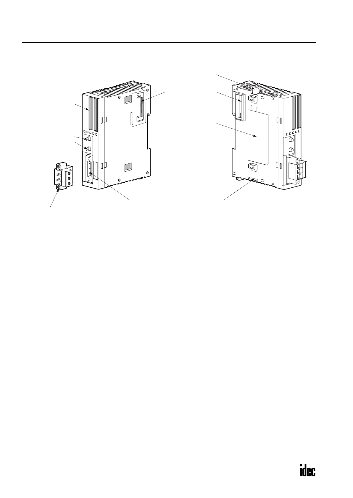
Parts Description
(1) LED Indicators
(2) Pushbuttons
PB1
PB2
(5) Unlatch Button
(6) Expansion Connector
(7) Module Label
(4) AS-Interface Cable Connector
(3) AS-Interface Cable Terminal Block
(supplied with the AS-Interface master module)
(5) Unlatch Button
(1) LED Indicators Status LEDs: Indicate the AS-Interface bus status.
I/O LEDs: Indicate the I/O status of the slave specified by the address LEDs.
Address LEDs: Indicate slave addresses.
(2) Pushbuttons Used to select slave addresses, change modes, and store configuration.
(3) AS-Interface Cable Terminal Block
Connects the AS-Interface cable.
One terminal block is supplied with the AS-Interface master module.
When ordering separately, specify Type No. FC4A-PMT3P and quantity
(package quantity: 2).
(4) AS-Interface Cable Connector
Installs the AS-Interface cable terminal block.
(5) Unlatch Button Used to unlatch the AS-Interface master module from the CPU or I/O module.
(6) Expansion Connector Connects to the CPU and other I/O modules.
(Applicable CPU modules are 20-I/O relay output and 40-I/O slim types.)
(7) Module Label Indicates the AS-Interface master module Type No. and specifications.
2-2 MICROSMART AS-INTERFACE MASTER MODULE USER’S MANUAL
Page 12

2: MODULE SPECIFICATIONS
Specifications
General Specifications
Operating Temperature 0 to 55°C (operating ambient temperature, no freezing)
Storage Temperature –25 to +70°C (no freezing)
Relative Humidity Level RH1, 30 to 95% (non-condensing)
Pollution Degree 2 (IEC 60664)
Degree of Protection IP20
Corrosion Immunity Free from corrosive gases
Altitude
Vibration Resistance
Shock Resistance
External Power Supply AS-Interface power supply, 29.5 to 31.6V DC
AS-Interface Current Draw
Effect of Improper Input Connection No damage
Connector on Mother Board MSTB2.5/3-GF-5.08BK (Phoenix Contact)
Connector Insertion/Removal Durability 100 times minimum
Internal Current Draw
AS-Interface Master Module
Power Consumption
Weight 85g
Operation: 0 to 2,000m (0 to 6,565 feet)
Transport: 0 to 3,000m (0 to 9,840 feet)
When mounted on a DIN rail:
10 to 57 Hz amplitude 0.075 mm, 57 to 150 Hz acceleration 9.8 m/s
2 hours per axis on each of three mutually perpendicular axes
When mounted on a panel surface:
2 to 25 Hz amplitude 1.6 mm, 25 to 100 Hz acceleration 39.2 m/s
90 minutes per axis on each of three mutually perpendicular axes
2
147 m/s
dicular axes (IEC 61131)
65 mA (normal operation)
110 mA maximum
80 mA (5V DC)
0 mA (24V DC)
540 mW (24V DC)
, 11 msec duration, 3 shocks per axis, on three mutually perpen-
2
2
Communication Specifications
When 1 through 19 slaves are connected: 3 msec
When 20 through 62 slaves are connected: 0.156 × (1 + N) msec
Maximum Bus Cycle
Maximum Slaves
Maximum I/O Points
Maximum Cable Length
Rated Bus Voltage 30V DC
where N is the number of active slaves
5 msec maximum when 31 standard or A/B slaves are connected
10 msec maximum when 62 A/B slaves are connected
Standard slaves: 31
A/B slaves: 62
When using a mix of standard slaves and A/B slaves together, the standard slaves can
only use addresses 1(A) through 31(A). Also, when a standard slave takes a cer tain
address, the B address of the same number cannot be used for A/B slaves.
Standard slaves: 248 total (124 inputs + 124 outputs)
A/B slaves: 434 total (248 inputs + 186 outputs)
AS-Interface Cable
2-wire Flat Cable
Single Wires 200 mm
MICROSMART AS-INTERFACE MASTER MODULE USER’S MANUAL 2-3
When using no repeater or extender: 100m
When using a total of 2 repeaters or extenders: 300m
Page 13
2: MODULE SPECIFICATIONS
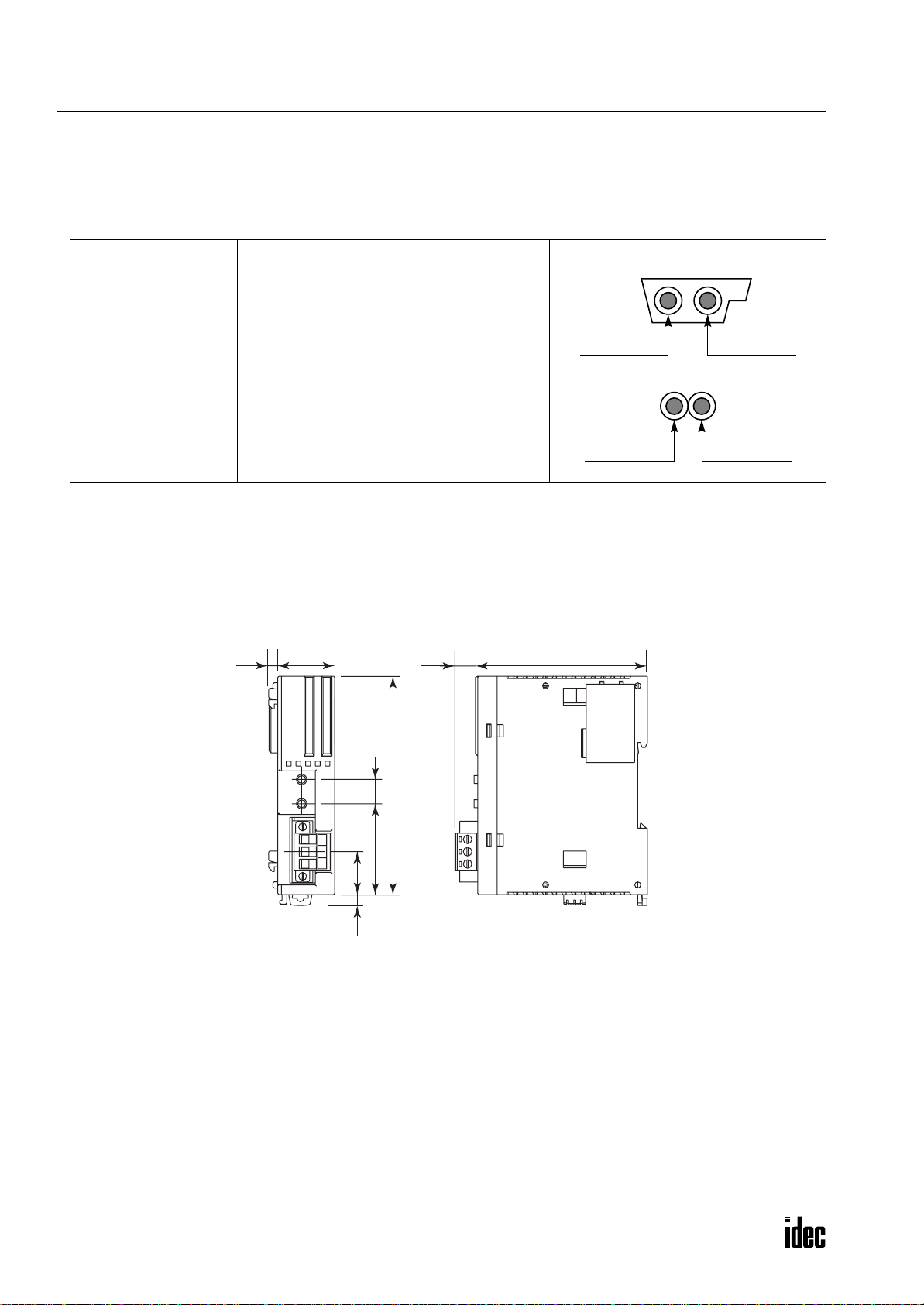
Applicable Cables
The AS-Interface cable transfers data and supplies power to the sensors and actuators connected to the bus. The following
cables can be used with the AS-Interface master module.
Applicable Cable Specifications
Cable Type Cable Size/Manufacturer Cross-sectional View
Cable sheath color: Yellow
Conductor cross section: 1.5 mm
2
AS-Interface
Standard Cable
2-wire Flat Cable
or
Single Wires
(See Note)
LAPP’s Cables
Type No: 2170228 (sheath material EPDM)
Type No: 2170230 (sheath material TPE)
Conductor cross section
Stranded wire: 0.5 to 1.0 mm
Solid wire: 0.75 to 1.5 mm
2
2
AWG: 20 to 16
AS-Interface – AS-Interface +
(blue) (brown)
AS-Interface – AS-Interface +
(blue) (brown)
Note: When using single wires, the maximum cable length is 200 mm. See “Maximum Cable Length” on page 2-3.
Dimensions
The AS-Interface master module has the same profile as all other MicroSmart modules for consistent mounting on a DIN
rail.
3.8
23.5
9.4 70.0
90.0
10
37.5
17.7
*8.5 mm when the clamp is pulled out.
4.5*
All dimensions in mm.
2-4 MICROSMART AS-INTERFACE MASTER MODULE USER’S MANUAL
Page 14
3: INSTALLATION AND WIRING
Introduction
This chapter describes the methods and precautions for installing and wiring the AS-Interface master module.
Before starting installation and wiring, be sure to read “Safety Precautions” in the beginning of this manual and under-
stand precautions described under Warning and Caution.
Warning
Caution
• Turn off the power to the AS-Interface master module before starting installation, removal, wiring, maintenance, and inspection of the AS-Interface master module. Failure to turn power off
may cause electrical shocks or fire hazard.
• Emergency stop and interlocking circuits must be configured outside the
circuit is configured inside the MicroSmart, failure of the MicroSmart may cause disorder of the
control system, damage, or accidents.
• Special expertise is required to install, wire, program, and operate the MicroSmart. People with-
out such expertise must not use the MicroSmart.
• Prevent metal fragments and pieces of wire from dropping inside the MicroSmart housing. Put a
cover on the MicroSmart modules during installation and wiring. Ingress of such fragments and
chips may cause fire hazard, damage, or malfunction.
• Do not touch the connector pins with hand, otherwise electrostatic discharge may damage the
internal elements.
Installation Location
The MicroSmart modules must be installed correctly for optimum
performance.
The MicroSmart is designed for installation in a cabinet. Do not
install the MicroSmart outside a cabinet.
The environment for using the
Use the MicroSmart in environments of pollution degree 2 (according to IEC 60664-1).
Make sure that the operating temperature does not drop below 0°C
or exceed 55°C. If the temperature does exceed 55°C, use a fan or
cooler.
Mount the
To eliminate excessive temperature build-up, provide ample venti-
lation. Do not install the MicroSmart near, and especially above,
any device which generates considerable heat, such as a heater,
transformer, or large-capacity resistor. The relati ve humidity should
be above 30% and below 95%.
The
direct sunlight, vibrations, or shocks. Do not use the MicroSmart in
an area where corrosive chemicals or flammable gases are present.
The modules should not be exposed to chemical, oil, or water
splashes.
MicroSmart on a vertical plane as shown at right.
MicroSmart should not be exposed to excessi v e dust, dirt, salt,
MicroSmart is “Pollution degree 2.”
MicroSmart. If such a
Mounting Clip
BNL6P
MICROSMART AS-INTERFACE MASTER MODULE USER’S MANUAL 3-1
Page 15

3: INSTALLATION AND WIRING
Assembling Modules
Caution
The following example demonstrates the procedure for assembling the 40-I/O type CPU module and the AS-Interface
master module together. When assembling the 20-I/O relay output type CPU module, take the same procedure.
1. When assembling an AS-Interface master mod-
ule, remove the expansion connector seal from
the 40-I/O type CPU module.
2. Place the CPU module and AS-Interface master module
side by side. Put the expansion connectors together for easy
alignment.
• Assemble MicroSmart modules together before mounting the modules onto a DIN rail. Attempt
to assemble modules on a DIN rail may cause damage to the modules.
• Turn off the power to the MicroSmart before assembling the modules. Failure to turn power off
may cause electrical shocks.
3. With the expansion connectors aligned correctly and the
blue unlatch button in the down position, press the CPU
module and AS-Interface master module together until the
latches click to attach the modules together firmly. If the
unlatch button is in the up position, push down the button to
engage the latches.
Note: When assembling other I/O modules with the AS-Interface
master module, take the same procedure.
Disassembling Modules
Caution
1. If the modules are mounted on a DIN rail, first remove the
modules from the DIN rail as described on page 3-3.
2. Push up the blue unlatch button to disengage the latches,
and pull the modules apart as shown.
Note: When disassembling other I/O modules from the AS-Interface master module, take the same procedure.
• Remove the MicroSmart modules from the DIN rail before disassembling the modules. Attempt
to disassemble modules on a DIN rail may cause damage to the modules.
• Turn off the power to the MicroSmart before disassembling the modules. Failure to turn power
off may cause electrical shocks.
Unlatch Button
Unlatch Button
3-2 MICROSMART AS-INTERFACE MASTER MODULE USER’S MANUAL
Page 16

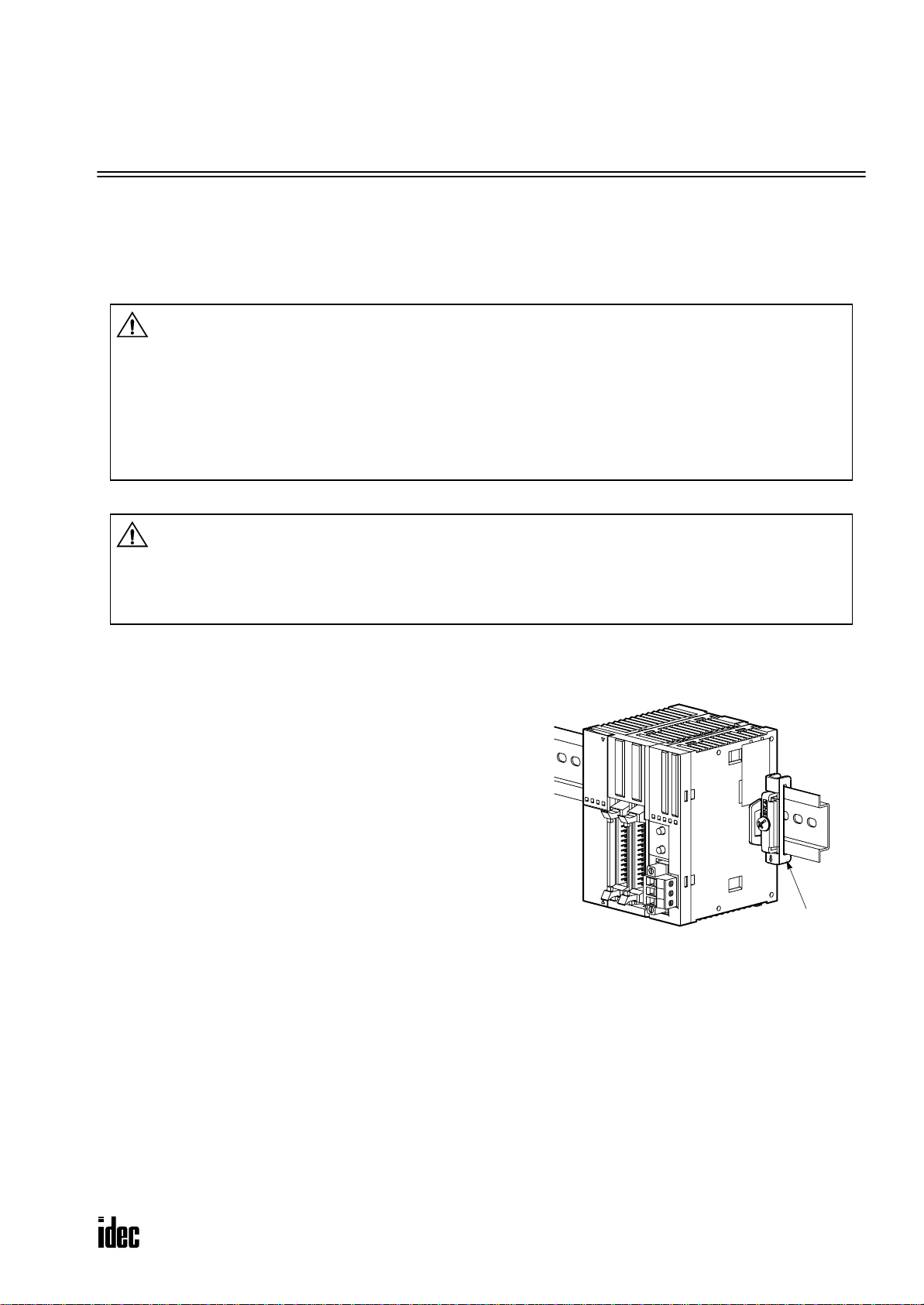
Mounting on DIN Rail
35-mm-wide DIN Rail
Clamp
(A)
(B)
Direct Mounting Strip
FC4A-PSP1P
3: INSTALLATION AND WIRING
Caution
• Install the MicroSmart modules according to instructions described in this user’s manual.
Improper installation will result in falling, failure, or malfunction of the MicroSmart.
• Mount the MicroSmart modules on a 35-mm-wide DIN rail or a panel surface.
Applicable DIN rail: IDEC’s BAA1000NP or BAP1000NP (1000mm/39.4” long)
1. Fasten the DIN rail to a panel using screws firmly.
2. Pull out the clamp from each MicroSmart module,
and put the groove of the module on the DIN rail.
Press the modules towards the DIN rail and push in
the clamps as shown on the right.
3. Use BNL6P mounting clips on both sides of the
MicroSmart modules to prevent moving sideways.
Removing from DIN Rail
1. Insert a flat screwdriver into the slot in the clamp.
Groove
35-mm-wide DIN Rail
Clamp
2. Pull out the clamps from the modules.
3. Turn the MicroSmart modules bottom out.
Direct Mounting on Panel Surface
MicroSmart modules can also be mounted on a panel
surface inside a console. When mounting a slim type
CPU module, AS-Interface master module, and other
expansion modules, use optional direct mounting strip
FC4A-PSP1P as described below.
Installing the Direct Mounting Strip
1. Remove the clamp from the module by pushing the
2. Insert the direct mounting strip into the slot where the
clamp inward.
clamp has been removed (A). Further insert the direct
mounting strip until the hook enters into the recess in
the module (B).
MICROSMART AS-INTERFACE MASTER MODULE USER’S MANUAL 3-3
Page 17

3: INSTALLATION AND WIRING
Removing the Direct Mounting Strip
(A)
1. Insert a flat screwdriver under the latch of the direct
mounting strip to release the latch (A).
(B)
2. Pull out the direct mounting strip (B).
Caution
• Reusing the Direct Mounting Strip
When you attempt to reuse a direct mounting strip, the hook may not catch on the recess sufficiently and may come out easily. When using a direct mounting strip again, be certain to push the
hook deeply into the recess.
Mounting Hole Layout for Direct Mounting on Panel Surface
Make mounting holes of ø4.3 mm as shown below and use M4 screws (6 or 8 mm long) to mount the AS-Interf ace master
module on the panel surface.
6.3
23.5
3.0
2-ø4.3
90.0
103.0
113.0±0.2
Direct Mounting Strip
FC4A-PSP1P
3-4 MICROSMART AS-INTERFACE MASTER MODULE USER’S MANUAL
Page 18

Terminal Connection
3: INSTALLATION AND WIRING
Caution
• Make sure that the operating conditions and environments are within the specification values.
• Be sure to connect the ground terminal on the CPU module to a proper ground, otherwise electri-
cal shocks may be caused.
• Do not touch live terminals, otherwise electrical shocks may be caused.
• Do not touch terminals immediately after power is turned off, otherwise electrical shocks may be
caused.
• When using ferrules, insert a wire to the bottom of the ferrule and crimp the ferrule.
• When connecting a stranded wire or multiple solid wires to a screw terminal block, use a ferrule.
Otherwise the wire may slip off the terminal block.
Ferrules, Crimping Tool, and Screwdriver for Phoenix Terminal Blocks
The screw terminal block for the AS-Interface cable can be wired with or without using ferrules on the end of the cable.
Applicable ferrules for the Phoenix terminal blocks and crimping tool for the ferrules are listed below. The screwdriver is
used for tightening the terminal screws and mounting screws on the terminal block. These ferrules, crimping tool, and
screwdriver are made by Phoenix Contact and are available from Phoenix Contact.
Type numbers of the ferrules, crimping tool, and screwdriv er listed below are the type numbers of Phoenix Contact. When
ordering these products from Phoenix Contact, specify the Order No. and quantity listed below.
Ferrule Order No.
Quantity of Cables Cable Size Phoenix Type Order No. Pcs./Pkt.
2
AWG20 AI 0,5-8 WH 32 00 01 4 100
2
AWG18 AI 0,75-8 GY 32 00 51 9 100
2
AWG16 AI 1,5-8 BK 32 00 04 3 100
2
AWG20 AI-TWIN 2 x 0,5-8 WH 32 00 93 3 100
2
AWG18 AI-TWIN 2 x 0,75-8 GY 32 00 80 7 100
For 1-cable connection
For 2-cable connection
0.5 mm
0.75 mm
1.5 mm
0.5 mm
0.75 mm
Crimping Tool and Screwdriver Order No.
Tool Name Phoenix Type Order No. Pcs./Pkt. Tightening Torque Description
Crimping Tool CRIMPFOX ZA 3 12 01 88 2 1 — For crimping ferrules
Screwdriver SZS 0,6 x 3,5 12 05 05 3 10
0.5 to 0.6 N·m For tightening terminal screws
0.3 to 0.5 N·m For tightening mounting screws
MICROSMART AS-INTERFACE MASTER MODULE USER’S MANUAL 3-5
Page 19

3: INSTALLATION AND WIRING
AS-Interface Cable Wiring
Before wiring the AS-Interface cable, remo ve the AS-Interface cable terminal block from the AS-Interface cable connector
on the AS-Interface master module.
AS-Interface specifies use of brown cables for the AS-Interf ace + line, and blue cables for the AS-Interface – line. Connect
the cables to match the color labels on the terminal block. Tighten the terminal screws to a torque of 0.5 to 0.6 N·m.
Insert the terminal block to the connector on the AS-Interface master module, and tighten the mounting screws to a torque
of 0.3 to 0.5 N·m.
Use a ferrule.
Brown AS-Interface +
Brown Label
Blue AS-Interface –
Use a ferrule. Blue Label
Power Supply
Caution
Power Supply Wiring Diagram
A recommended power supply wiring diagram is shown below. Use a common power switch for both the CPU module
power supply and AS-Interf ace power supply to make sure that both power supplies are turned on and of f at the same time.
AC Power
Power Switch
• When turning off the power to the CPU module, also turn off the AS-Interface power supply. If
the CPU module is powered down and up while the AS-Interface po wer remains on, AS-Interface
communication may stop due to a configuration error, resulting in a communication error.
• Turn on the AS-Interface power supply no later than the CPU module power supply , e xcept when
slave address 0 exists on the network. The two power supplies may be turned off in any order.
Slim Type CPU Module
FC4A-D40K3
AS-Interface Master Module
FC4A-AS62M
AS-Interface Cable Connector
CPU Module Power Supply
AS-Interface Power Switch (Note)
AS-Interface Power Supply
VLSV (very low safety voltage)
Note: A failed slave can be replaced with a new slave with address 0 without turning of f the power to the CPU module and
the AS-Interface line. But, if power has been turned off before replacing the slaves, install a new slave with address 0 and
take one of the following steps, because the AS-Interface master module has to be initialized to enable communication.
24V DC
Slave 2
30V DC
Slave 1
• Disconnect the AS-Interface cable connector and turn on both power supplies. Five seconds later, connect the AS-Interface
cable connector.
• Turn on the CPU module power supply first. Five seconds later, turn on the AS-Interface power supply.
3-6 MICROSMART AS-INTERFACE MASTER MODULE USER’S MANUAL
Page 20

4: OPERATION BASICS
Introduction
This chapter describes general information about simple operating procedures for the basic AS-Interface system from programming WindLDR on a computer to monitoring the slave operation.
AS-Interface System Setup
The sample AS-Interface system consists of the following devices:
Name Type No. Description
MicroSmart Slim Type CPU Module FC4A-D20RK1 System program version 201 or later
MicroSmart AS-Inter face Master Module FC4A-AS62M —
WindLDR FC9Y-LP2CDW Version 4.21 or higher
1 unit
AS-Interface Standard Slave —
AS-Interface Power Supply PS2R-Q30ABL Output 30.5V DC, 2.4A (73W)
Connect the devices as shown below.
Address 0
ID: 0, I/O: 7, ID2: F, ID1: 7
Computer Link Cable 4C
FC2A-KC4C
3m (9.84 ft.) long
Slim Type CPU Module
FC4A-D20RK1
AS-Interface Power Supply
Standard Slave
Address 0
ID: 0, I/O: 7, ID2: F, ID1: 7
AS-Interface Master Module
FC4A-AS62M
Standard
AS-Interface Cable
MICROSMART AS-INTERFACE MASTER MODULE USER’S MANUAL 4-1
Page 21

4: OPERATION BASICS
Selecting the PLC Type
Start WindLDR on a computer.
1. From the
2. Select MicroSmart-20Ry.
3. Click OK to save changes and return to the ladder editing screen.
WindLDR menu bar, select Configure > PLC Selection. The PLC Selection dialog box appears.
Function Area Settings
Use of the AS-Interface master module must be selected in the Function Area Settings dialog box.
1. From the WindLDR menu bar, select Configure > Function Area Settings. The Function Area Settings dialog box
appears.
2. Select the Others tab.
3. Make sure of a check mark in the check box on the left of Use AS-Interface Master Module.
This check box is checked as default. Since this setting relates to the user program, download the user program to the CPU
module after changing any of these settings.
If the ERR LED on the CPU module goes on when the AS-Interface master module is connected, download the user program to the CPU module after making the above setting.
4-2 MICROSMART AS-INTERFACE MASTER MODULE USER’S MANUAL
Page 22

4: OPERATION BASICS
Assigning a Slave Address
AS-Interface compatible slave de vices are set to address 0 at f actory. Connect the sla v e to the AS-Interface master module
as shown on page 4-1. Do not connect two or more slav es with slave address 0, otherwise the AS-Interface master module
cannot recognize slave addresses correctly.
1. Power up the
Note: When slave address 0 is not mounted on the AS-Interface bus, the CPU module power supply and the AS-Interface
power supply can be turned on at the same time. See page 3-6.
MicroSmart CPU module first. Approximately 5 seconds later, turn on the AS-Interface power supply.
2. From the WindLDR menu bar, select Configure > AS-Interface Master to open the Configure AS-Interface Master
dialog box. Press Refresh to collect slave information and update the screen display. (When configuration in the master module is complete, you do not have to press Refresh since the screen display is updated automatically.)
On the Configure AS-Interface Master dialog box, slave address 0 is shaded with yellow. This means that the master module has found slave address 0 on the AS-Interface bus. The CDI for address 0 shows 07F7 (ID: 0, I/O: 7, ID2: F, ID1: 7).
3. Click the slave address “00” to open the Change Slave Address dialog box for slave 0. To assign slave address 1 to the
slave, enter 1 in the New Address field and click OK.
Yellow Shade
Click slave address 0 to open the
Change Slave Address dialog box.
CDI: Configuration Data Image
PCD: Permanent Configuration Data
The new address “01” is shaded with
yellow to indicate that the address
assignment is complete.
4. When changing slave addresses on
other slaves, continue from step 3 if
it is possible to wire the slave without turning off power, or from step
1 if the CPU module is shut down.
MICROSMART AS-INTERFACE MASTER MODULE USER’S MANUAL 4-3
Yellow Shade
Page 23

4: OPERATION BASICS
Configuring a Slave
Next, you have to set the sla ve con figuration in the AS-Interface master module, either by using pushbuttons PB1 and PB2
on the AS-Interface master module or WindLDR.
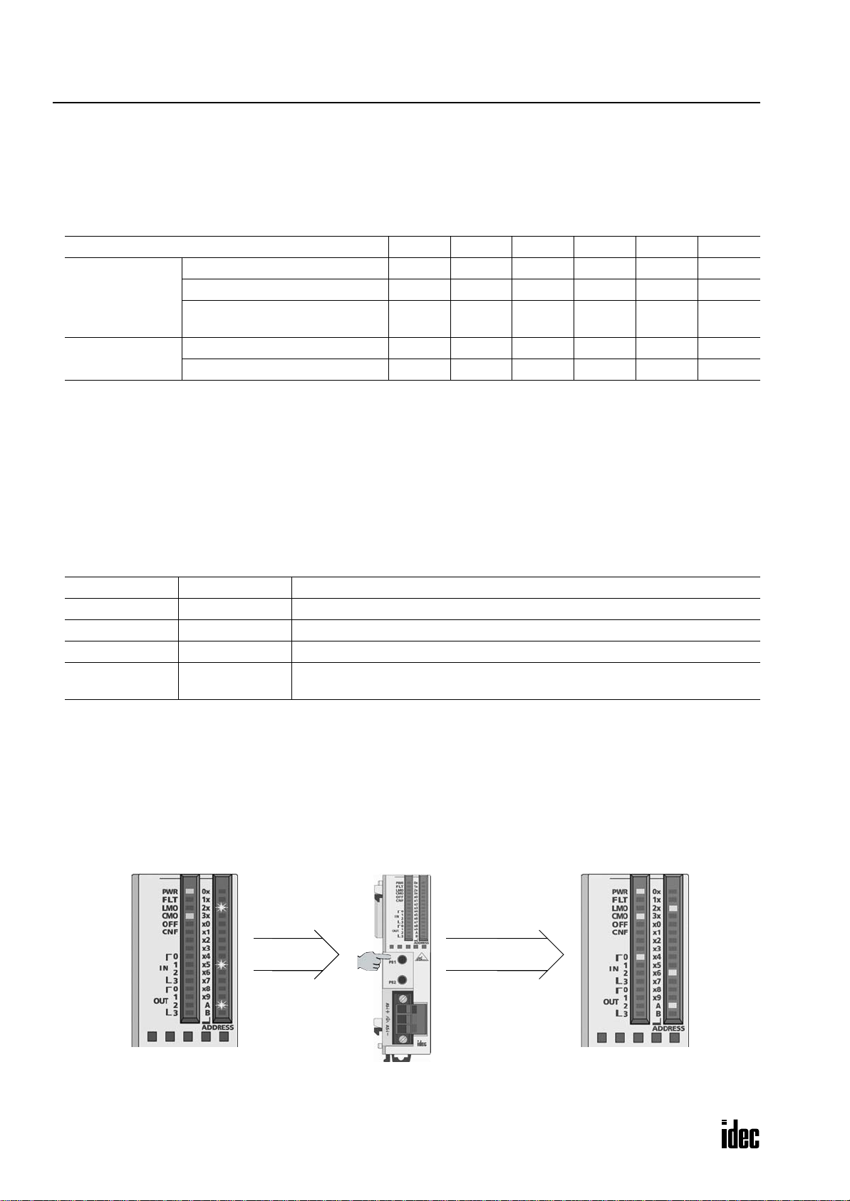
Configuration Using Pushbuttons PB1 and PB2
Shut down and
power up again.
Press PB1 and PB2. Press PB2. Press PB1.
1. Check that PWR LED and CMO LED on the AS-Interface master module are on (normal protection mode).
2. Press pushbuttons PB1 and PB2 together for 3 seconds. CMO LED turns off and LMO LED turns on (protected mode).
3. Press pushbutton PB2 for 3 seconds. CNF LED flashes (configuration mode).
4. About 5 seconds later, press pushbutton PB1 for 3 seconds. All I/O LEDs blink once to complete configuration.
5. Shut down the CPU module and AS-Interface master module, and power up again. Check that FLT LED is off, which
indicates that configuration is complete.
6. Use
WindLDR to view slav e information on the Configure AS-Interface Master dialog box and check that all slaves are
recognized correctly.
4-4 MICROSMART AS-INTERFACE MASTER MODULE USER’S MANUAL
Page 24

Configuration Using WindLDR
4: OPERATION BASICS
Slave configuration can be set using
WindLDR in two ways; using the Auto Configuration or Manual Configuration but-
ton on the Configure AS-Interface Master dialog box.
1. Click the A
uto Configuration button to store the configuration information (LDS, CDI, PI) of the connected slaves to
the EEPROM (LPS, PCD, PP) in the AS-Interface master module. For details, see page 7-3.
The auto configuration automatically stores the information of slaves found on the AS-Interf ace bus to the EEPROM in the
master module, and this completes configuration. Another method of configuration is manual configuration as follows.
2. Click the PCD value “FFFF” of slave address 01 to open the Configure Slave 01A dialog box.
3. Enter the same value as CDI “07F7” to the PCD field. (Set FFFF to PCD values of all unused slaves.)
4. Select initial settings of parameters 0 through 3, if required.
Yellow Shade
5. Click the M
anual Configuration button to store the selected PCD and parameter values to the master module.
6. Check that the blue shade appears at slave address 01. Now, configuration is complete.
Blue Shade
MICROSMART AS-INTERFACE MASTER MODULE USER’S MANUAL 4-5
Page 25

4: OPERATION BASICS
Monitoring Digital I/O, and Changing Output Status and Parameters
While the MicroSmart is communicating with AS-Interface slaves through the AS-Interface bus, operating status of ASInterface slaves can be monitored using WindLDR on a PC. Output statuses and parameter image (PI) of slaves connected
to the AS-Interface master module can also be changed using WindLDR.
1. From the
tor AS-Interface Slaves in the pull-down menu. The Monitor AS-Interface Slaves dialog box appears.
Active slaves are indicated with blue shade.
Next step is to change output status of the active slave.
2. Click the output of slave address 01 to open the Slave Status 01A dialog box.
3. Click the On or Off button to change the statuses of outputs O0 through O3 and parameters (PI) P0 through P3 as
required.
WindLDR menu bar, select Online > Monitor. From the WindLDR menu bar, select Online, and select Moni-
Blue Shade
The selected parameters (PI) are in effect until the CPU module is shut down. When the CPU module is po wered up again,
the parameter values (PP) selected in the slave configuration procedure (page 4-4) will take effect. To store the changed
parameter values to the AS-Interface master module EEPROM, execute the Copy PI to PP command by storing 0306,
0100, 0000, 0000, 0001 to data registers D1941 through D1945. See page 6-17.
4-6 MICROSMART AS-INTERFACE MASTER MODULE USER’S MANUAL
Page 26

4: OPERATION BASICS
Troubles at System Start-up
The following table summarizes possible troubles at system start-up, probable causes and actions to be taken.
Trouble Cause and Action
• AS-Interface power is not supplied to the AS-Interface master module. Check that
PWR LED is off.
(power)
FLT LED is on.
(fault)
LMO LED is on.
(local mode)
wiring is correct and AS-Inter face power is supplied.
• Power is not supplied from the CPU module to the AS-Interface master module.
Check the connection between the CPU module and the AS-Interface master module.
• Slave configuration on the bus is incorrect. Use the WindLDR slave monitor function
to check that slaves are connected correctly. Perform configuration, if necessar y. For
the configuration method, see page 7-1.
If FLT LED remains on even though slaves are connected correctly and configuration is
completed, either disconnect and reconnect the AS-Interface connector, or turn off and
on the AS-Interface power supply.
The CPU module fails to communicate with the AS-Interface master module. Check the
following points.
• Is the CPU module compatible with AS-Interface? Check the Type No. of the CPU
module.
• Is the system program of the CPU module 201 or higher? Check the system program
version in the Online > PLC Status dialog box in WindLDR.
• Is a check mark put in the check box “Use AS-Interface Master Module” in WindLDR
Function Area Settings? The box is checked as default. If not, put a check mark and
download the user program to the CPU module.
OFF LED is on.
(offline)
Slave operation is unstable.
• While a slave of address 0 was connected, power was turned on. After changing the
slave address, power up again. For the address changing method, see page 7-2.
• Check if there are two or more slaves with the same address. Each slave must have
a unique address. If two slaves have the same address and same identification
codes (ID, I/O, ID2, ID1), the AS-Interface master module may fail to detect an error.
When changing the duplicate slave address using WindLDR, remove one of the
slaves from the bus.
MICROSMART AS-INTERFACE MASTER MODULE USER’S MANUAL 4-7
Page 27

4: OPERATION BASICS
4-8 MICROSMART AS-INTERFACE MASTER MODULE USER’S MANUAL
Page 28
5: PUSHBUTTONS AND LED INDICATORS
PB1
PB2
Introduction
This chapter describes the operation of pushbuttons PB1 and PB2 on the AS-Interface master module to change operation
modes, and also explains the functions of address and I/O LED indicators.
Pushbutton Operation
The operations performed by pushbuttons PB1 and PB2 on the front of the AS-Interface master module depend on the
duration of being pressed. A “long press” switches the operation mode, and a “short press” switches the slave being monitored on the I/O LEDs. If the duration of pressing PB1 or PB2 does not correspond to either of these, the status of the ASInterface master module does not change.
Long Press
A “long press” takes effect when you press either pushbutton PB1 or PB2 or both for 3 seconds or
more. Use the long press to change the operation mode of the AS-Interface master module or to
save the configuration data to the AS-Interface master module EEPROM.
Short Press
A “short press” takes effect when you press either pushbutton PB1 or PB2 for 0.5 second or less.
Use the short press to change the slave address when monitoring slave I/O status on the AS-Interface master module LED indicators.
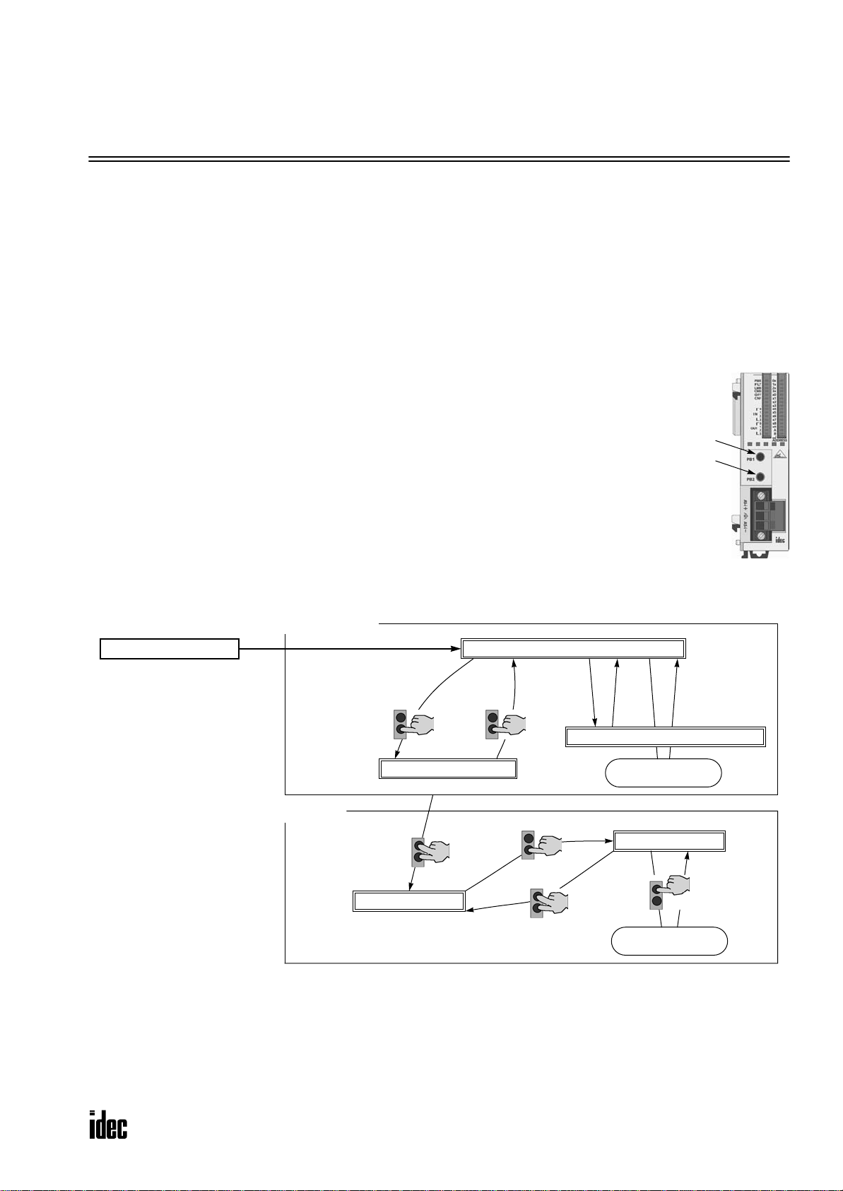
Transition of AS-Interface Master Module Modes Using Pushbuttons
Connected Mode
MicroSmart Power ON
PB2 PB2
Normal Protected Offline
Note:
All pushbutton operations
for changing modes are
“long press.”
*1 Pushbutton operation or execution of the ASI command Go to Normal Protected Of fline.
*2 Pushbutton operation or execution of the ASI command Go to Normal Protected Mode.
*3 Execution of the ASI command Prohibit Data Exchange.
*4 Execution of the ASI command Enable Data Exchange.
*5 Configuration is done by clicking the Auto Configuration or Manual Configuration button in WindLDR. The configuration
data is saved to the AS-Interface master module EEPROM.
Local Mode
PB1
PB2
Protected Mode
Normal Protected Mode
*2*1
Normal Protected Data Exchange Off
PB2
PB1
PB2
*5*4*3
Store Configuration
Data to EEPROM
Configuration Mode
PB1
Store Configuration
Data to EEPROM
MICROSMART AS-INTERFACE MASTER MODULE USER’S MANUAL 5-1
Page 29

5: PUSHBUTTONS AND LED INDICATORS
AS-Interface Master Module Operation Modes
The AS-Interface master module has tw o modes of operation: connected mode is used for actual operation, and local mode
is used for maintenance purposes.
Connected Mode
In connected mode, the CPU module communicates with the AS-Interface master module to monitor and control each
slave. Connected mode is comprised of the following three modes.
Normal Protected Mode
When the CPU module is powered up, the AS-Interface master module initially enters normal protected mode of connected mode if no error occurs. This is the normal operation mode for the AS-Interface master module to perform data
communication with the connected slaves.
If the configuration data stored in the AS-Interface master module do not match the currently connected slave configuration, the FL T LED on the front of the AS-Interface master module goes on. Execute con figuration using the pushbuttons on
the AS-Interface master module. Configuration can also be done using WindLDR. See page 7-3.
Normal Protected Offline
The AS-Interface master module stops communication with all slaves and enables offline operation (initialization of the
master module). In this mode, the CPU module cannot monitor the slave status.
To enter normal protected offline from normal protected mode, either long-press the PB2 button or execute the ASI command Go to Normal Protected Offline. To return to normal protected mode and resume data communication, either longpress the PB2 button again or execute the ASI command Go to Normal Protected Mode. For details about the ASI commands, see page 6-17.
Normal Protected Data Exchange Off
Data communication with all slaves is prohibited. To enter this mode, execute the ASI command Prohibit Data Exchange.
To return to normal protected mode and resume data communication, execute the ASI command Enable Data Exchange.
For details about the ASI commands, see page 6-17.
When auto configuration or manual configuration is executed on WindLDR, the AS-Interface master module enters this
mode during configuration.
Local Mode
In local mode, the CPU module does not communicate with the AS-Interface master module. Local mode is used to carry
out maintenance operations such as checking the configuration and slave inputs. Use the input LEDs to check the slave
input data during operation.
When the CPU module is powered up, the AS-Interface master module initially enters normal protected mode of connected mode if no error occurs. T o switch from an y of connected mode to local mode (protected mode), long-press the PB1
and PB2 buttons simultaneously. It is not possible to switch from local mode back to connected mode using the pushbuttons. To return to connected mode, shut down the CPU module and power up again.
Local mode is comprised of two modes: protected mode and configuration mode.
Protected Mode
This mode operates the slaves in accordance with the slav e configuration data stored in the AS-Interface master module. If
the configuration data stored in the AS-Interface master module does not match the currently connected slave configuration, the FLT LED on the front of the AS-Interface master module goes on, and slaves are not operated correctly.
To enter protected mode from any of connected mode, long-press the PB1 and PB2 buttons simultaneously.
Configuration Mode
This mode switches all currently connected slaves to active, regardless of the slave configuration data stored in the ASInterface master module. To store the current slave configuration data to the AS-Interface master module EEPROM, long
press the PB1 button. This way, configuration is executed.
To enter configuration mode from protected mode, long-press the PB2 button. To return to protected mode, long-press the
PB1 and PB2 buttons simultaneously.
5-2 MICROSMART AS-INTERFACE MASTER MODULE USER’S MANUAL
Page 30

5: PUSHBUTTONS AND LED INDICATORS
LED Indicators
The LED indicators on the AS-Interface master module consist of status LEDs, I/O LEDs, and address LEDs.
Address LEDs (0x to 3x)
Status LEDs
Address LEDs (x0 to x9)
Input LEDs
Output LEDs
Address LEDs (A and B)
LED Indicators Description
PWR
(AS-Interface power supply)
FLT (Fault)
Status LEDs
Input LEDs IN0-IN3
Output LEDs OUT0-OUT3
Address LEDs
LMO (Local mode)
CMO (Connected mode)
OFF (Offline)
CNF (Configuration)
0x-3x (place of 10)
x0-x9 (place of 1)
A, B (A or B slave)
Indicates the status of the AS-Interface power supply for the AS-Interface
master module.
Goes on when the AS-Interface power is supplied sufficiently.
Indicates the AS-Interface configuration status.
Goes on when the permanent configuration data (PCD) stored in the ASInterface master module EEPROM does not match the current slave configuration, or configuration data image (CDI). Then, configuration is not
complete or an error was found on the AS-Inter face bus.
Indicates the mode of the AS-Interface master module.
Goes on when the AS-Interface master module is in local mode.
Goes off when the AS-Inter face master module is in connected mode.
Indicates the mode of the AS-Interface master module.
Goes on when the AS-Interface master module is in connected mode.
Goes off when the AS-Inter face master module is in local mode.
Indicates the operating status of the AS-Interface master module.
Goes on when the AS-Interface master module is in normal protected
offline.
Indicates the configuration status of the AS-Interface master module.
Flashes when the AS-Interface master module is in configuration mode.
Indicates the operating status of four inputs at the address indicated by
the address LEDs.
Goes on when the corresponding input at the indicated address is on.
Indicates the operating status of four outputs at the address indicated by
the address LEDs.
Goes on when the corresponding output at the indicated address is on.
Indicates the slave address of 0A through 32B.
Goes on when the selected address exists.
Flashes when the selected address does not exist.
MICROSMART AS-INTERFACE MASTER MODULE USER’S MANUAL 5-3
Page 31
5: PUSHBUTTONS AND LED INDICATORS
Status LEDs
The operation modes of the AS-Interface master module can be changed by pressing the pushbuttons on the front of the
AS-Interface master module or by executing ASI commands. The operation modes can be confirmed on the six status
LEDs on the AS-Interface master module. For details about the ASI commands, see page 6-17.
Status LED Indication
Status LED PWR FLT LMO CMO OFF CNF
Normal Protected Mode ON
Connected Mode
Local Mode
*1: Goes off when AS-Inter face power is not supplied.
*2: Goes on when an error is found on the AS-Inter face bus.
Normal Protected Offline ON
Normal Protected
Data Exchange Off
Protected Mode ON
Configuration Mode ON
ON
*1
*1
*1
*1
*1
*2
OFF
ON OFF ON ON OFF
ON OFF ON OFF OFF
*2
OFF
*2
OFF
OFF ON OFF OFF
ON OFF OFF OFF
ON OFF OFF Flash
Address LEDs and I/O LEDs
The operating status and I/O status of each slave can be monitored on the address LEDs and I/O LEDs on the front of the
AS-Interface master module.
Slave Operating Status
The operating status of each slave can be determined by viewing the address LEDs and I/O LEDs.
Address LED I/O LED Description
ON ON or OFF The slave at this address is active.
ON Flash The slave at this address is active, but has an error.
Flash OFF This address is not assigned a slave.
OFF OFF
The AS-Interface bus communication is disabled because the AS-Interface power
is not supplied or the AS-Interface master module is in normal protected of fline.
Slave I/O Status
The I/O status of each slave can be monitored on the address LEDs and I/O LEDs. Use the short press to change the slav e
address when monitoring slave I/O status on the AS-Interface master module. A short press on PB1 increments the
address. At the last address (31B), another short press will return to the first address (0A). A short press on PB2 decrements the address. At the first address (0A), another short press will return to the last address (31B).
The figures below illustrate what happens when you press the PB1 button while the address LEDs indicate 25A. The
address LEDs increment to 26A where a slave is assigned. Note that the address LEDs flash if no slave is assigned.
Short press
on PB1
I/O LEDs
indicate statuses
Monitoring Slave Address 25A
Address LEDs are flashing since
no slave is assigned.
5-4 MICROSMART AS-INTERFACE MASTER MODULE USER’S MANUAL
Monitoring Slave Address 26A
Address LEDs go on and I/O
LEDs indicate the statuses.
Page 32

6: AS-INTERFACE OPERANDS
Introduction
This chapter describes AS-Interface operands, or internal relays M1300 through M1997 and data registers D1700 through
D1999, assigned in the CPU module to control and monitor the AS-Interface bus, and provides detailed description about
internal relays allocated to SwitchNet™ control units for use as slaves in the AS-Interface network. Also describes ASI
commands used to update AS-Interface operands in the CPU module or to control the AS-Interface master module.
AS-Interface Operand Allocation Numbers
The I/O data and parameters of slaves on the AS-Interface bus, the status of the AS-Interface bus, and various list information of the slaves are allocated to the AS-Interface master module EEPROM. This information is called AS-Interface
objects, which can be accessed through the AS-Interface operands. The allocation is shown in the table below.
MicroSmart CPU Module
Operand Allocation No. AS-Interface Object
AS-Interface
Internal
Relays
M1300-M1617 3.0 R
M1620-M1937 3.0 W
M1940-M1997 1.0 R Status information
Precessing
Time (msec)
*1
Read/
Write
*2
*2
D1700-D1731 5.2 R Analog input
D1732-D1763 5.2 W Analog output
*2
*2
*2
*2*3
*2
*2
AS-Interface
Data
Registers
D1764-D1767 1.0 R
D1768-D1771 1.0 R
D1772-D1775 1.0 R
D1776-D1779 1.0 R/W
D1780-D1843 10.4 R
D1844-D1907 10.4 R/W
D1908-D1923 3.0 R
D1924-D1939 3.0 R/W
AS-Interface Master Module EEPROM
Digital input (IDI)
Digital output (ODI)
*4
*4
*5
*5
List of active slaves (LAS)
List of detected slaves (LDS)
List of peripheral fault slaves (LPF)
List of projected slaves (LPS)
Configuration data image (CDI)
*2*3
Permanent configuration data (PCD)
Parameter image (PI)
*2*3
Permanent parameter (PP)
Operand
Updated
Every scan
Each time ASI
command is
executed
D1940 0.7 R/W Slave 0 ID1 code
D1941-D1945 — R/W For ASI command description —
D1946-D1999 — — (reserved) —
*1: The time required to update the operand data. When using the AS-Inter face master module, the scan time increases by
a minimum of 10 msec.
*2: These AS-Inter face operand data can be read or written using WindLDR. For details, see page 7-1.
*3: The LPS, PCD, and PP are set and downloaded to a PLC using WindLDR. For details, see page 7-3.
*4: IDI (input data image), ODI (output data image)
*5: The analog I/O data is updated only when an analog slave is connected to the AS-Inter face bus.
Processing Time
AS-Interface internal relays for digital I/O and status information, and data registers for LAS, LDS, LPF are updated
in every scan. Data registers for analog I/O operands are
also updated in every scan only when analog I/O are connected to the AS-Interface bus. The processing times for
these AS-Interface operands are shown in the table above.
Other AS-Interface data registers are updated when an
ASI command is executed in the CPU module. For the
processing times of the ASI commands, see page 6-17.
MICROSMART AS-INTERFACE MASTER MODULE USER’S MANUAL 6-1
Ladder
Processing
AS-Interface
Processing
Other
Processing
MicroSmart CPU Module
AS-Interface Operands
Constantly
Updated Operands
M1300-M1997
D1700-D1775
ASI Command
D1941-D1945
ASI Command
Updated Operands
AS-Interface
Master Module
AS-Interface Objects
IDI, ODI
Status Information
Analog I/O
LAS, LDS, LPF
LPS, CDI, PCD
PI, PP
Slave 0 ID1D1776-D1940
Page 33

6: AS-INTERFACE OPERANDS
I/O Data
The AS-Interface master module can process digital I/O data and analog I/O data. Digital I/O data can be a maximum of 4
digital inputs and 4 digital outputs per slave. Analog I/O data consists of 4 channels of 16-bit analog input or output data
per slave.
Digital I/O Data of Standard Slaves and Expansion Slaves
The digital I/O data for standard slaves and A/B slaves (sensors and actuators) on the AS-Interface bus are allocated to the
AS-Interface internal relays in the ascending order starting with slave 0. The input data image (IDI) for each slave is allocated to M1300 through M1617, and the output data image (ODI) is allocated to M1620 through M1937. For example, in
the case of slave 3A, the input data is allocated to M1314 (DI0) through M1317 (DI3), and the output data is allocated to
M1634 (DO0) through M1637 (DO3).
•
Digital Input Data Image
Data Format
Input Data Image (IDI)
M1300 Byte 0 Slave 1(A) (Slave 0)
M1310 Byte 1 Slave 3(A) Slave 2(A)
M1320 Byte 2 Slave 5(A) Slave 4(A)
M1330 Byte 3 Slave 7(A) Slave 6(A)
M1340 Byte 4 Slave 9(A) Slave 8(A)
M1350 Byte 5 Slave 11(A) Slave 10(A)
M1360 Byte 6 Slave 13(A) Slave 12(A)
M1370 Byte 7 Slave 15(A) Slave 14(A)
M1380 Byte 8 Slave 17(A) Slave 16(A)
M1390 Byte 9 Slave 19(A) Slave 18(A)
M1400 Byte 10 Slave 21(A) Slave 20(A)
M1410 Byte 11 Slave 23(A) Slave 22(A)
M1420 Byte 12 Slave 25(A) Slave 24(A)
M1430 Byte 13 Slave 27(A) Slave 26(A)
M1440 Byte 14 Slave 29(A) Slave 28(A)
M1450 Byte 15 Slave 31(A) Slave 30(A)
M1460 Byte 16 Slave 1B —
M1470 Byte 17 Slave 3B Slave 2B
M1480 Byte 18 Slave 5B Slave 4B
M1490 Byte 19 Slave 7B Slave 6B
M1500 Byte 20 Slave 9B Slave 8B
M1510 Byte 21 Slave 11B Slave 10B
M1520 Byte 22 Slave 13B Slave 12B
M1530 Byte 23 Slave 15B Slave 14B
M1540 Byte 24 Slave 17B Slave 16B
M1550 Byte 25 Slave 19B Slave 18B
M1560 Byte 26 Slave 21B Slave 20B
M1570 Byte 27 Slave 23B Slave 22B
M1580 Byte 28 Slave 25B Slave 24B
M1590 Byte 29 Slave 27B Slave 26B
M1600 Byte 30 Slave 29B Slave 28B
M1610 Byte 31 Slave 31B Slave 30B
7
(DI3)
6
(DI2)
5
(DI1)
4
(DI0)
3
(DI3)
2
(DI2)
1
(DI1)
(DI0)
0
6-2 MICROSMART AS-INTERFACE MASTER MODULE USER’S MANUAL
Page 34

6: AS-INTERFACE OPERANDS
• Digital Output Data Image
Data Format
Output Data Image (ODI)
M1620 Byte 0 Slave 1(A) (Slave 0)
M1630 Byte 1 Slave 3(A) Slave 2(A)
M1640 Byte 2 Slave 5(A) Slave 4(A)
M1650 Byte 3 Slave 7(A) Slave 6(A)
M1660 Byte 4 Slave 9(A) Slave 8(A)
M1670 Byte 5 Slave 11(A) Slave 10(A)
M1680 Byte 6 Slave 13(A) Slave 12(A)
M1690 Byte 7 Slave 15(A) Slave 14(A)
M1700 Byte 8 Slave 17(A) Slave 16(A)
M1710 Byte 9 Slave 19(A) Slave 18(A)
M1720 Byte 10 Slave 21(A) Slave 20(A)
M1730 Byte 11 Slave 23(A) Slave 22(A)
M1740 Byte 12 Slave 25(A) Slave 24(A)
M1750 Byte 13 Slave 27(A) Slave 26(A)
M1760 Byte 14 Slave 29(A) Slave 28(A)
M1770 Byte 15 Slave 31(A) Slave 30(A)
M1780 Byte 16 Slave 1B —
M1790 Byte 17 Slave 3B Slave 2B
M1800 Byte 18 Slave 5B Slave 4B
M1810 Byte 19 Slave 7B Slave 6B
M1820 Byte 20 Slave 9B Slave 8B
M1830 Byte 21 Slave 11B Slave 10B
M1840 Byte 22 Slave 13B Slave 12B
M1850 Byte 23 Slave 15B Slave 14B
M1860 Byte 24 Slave 17B Slave 16B
M1870 Byte 25 Slave 19B Slave 18B
M1880 Byte 26 Slave 21B Slave 20B
M1890 Byte 27 Slave 23B Slave 22B
M1900 Byte 28 Slave 25B Slave 24B
M1910 Byte 29 Slave 27B Slave 26B
M1920 Byte 30 Slave 29B Slave 28B
M1930 Byte 31 Slave 31B Slave 30B
7
(DO3)6(DO2)5(DO1)4(DO0)3(DO3)2(DO2)1(DO1)0(DO0)
Caution
• Immediately after power up, the digital I/O data of standard slaves and expansion slaves cannot
be accessed. Data communication between the CPU module and the connected slaves starts when
special internal relay M1945 (Normal_Operation_Active) turns on. Make sure that M1945 is on
before starting to access the slave I/O data.
MICROSMART AS-INTERFACE MASTER MODULE USER’S MANUAL 6-3
Page 35

6: AS-INTERFACE OPERANDS
Analog I/O Data of Analog Slaves
The I/O data for a maximum of seven analog slaves (four channels for each slave) on the AS-Interface bus is stored to ASInterface data registers in the CPU module. The analog slav e addresses (1 to 31) are in the ascending order. The input data
for each analog slave is allocated to data registers D1700 to D1731, and the output data is allocated to D1732 to D1763.
The AS-Interface master module is compliant with analog slave profile 7.3.
Caution
• The maximum number of analog slaves that can be connected to the AS-Interface bus is seven. Do
not connect eight or more analog slaves to one bus, otherwise the slaves will not function correctly.
• When data registers D1700 through D1731 allocated to analog inputs contain 7FFF, do not use this
data for programming, because this value is reserved for a special meaning as follows:
Unused channel on a slave allocated to analog slave. (For a channel on a slave not allocated an
analog slave, the corresponding data register holds an indefinite value.)
Data overflow.
Communication between the master and analog slave is out of synchronism.
• When using analog slaves, read the user’s manual for the analog slave to process the data properly.
•
Analog Input Data
Analog Input Channel No. Data Format
D1700 Bytes 0 and 1 Channel 1
D1701 Bytes 2 and 3 Channel 2
D1702 Bytes 4 and 5 Channel 3
D1703 Bytes 6 and 7 Channel 4
D1704 Bytes 8 and 9 Channel 1
D1705 Bytes 10 and 11 Channel 2
D1706 Bytes 12 and 13 Channel 3
D1707 Bytes 14 and 15 Channel 4
D1708 Bytes 16 and 17 Channel 1
D1709 Bytes 18 and 19 Channel 2
D1710 Bytes 20 and 21 Channel 3
D1711 Bytes 22 and 23 Channel 4
D1712 Bytes 24 and 25 Channel 1
D1713 Bytes 26 and 27 Channel 2
D1714 Bytes 28 and 29 Channel 3
D1715 Bytes 30 and 31 Channel 4
D1716 Bytes 32 and 33 Channel 1
D1717 Bytes 34 and 35 Channel 2
D1718 Bytes 36 and 37 Channel 3
D1719 Bytes 38 and 39 Channel 4
D1720 Bytes 40 and 41 Channel 1
D1721 Bytes 42 and 43 Channel 2
D1722 Bytes 44 and 45 Channel 3
D1723 Bytes 46 and 47 Channel 4
D1724 Bytes 48 and 49 Channel 1
D1725 Bytes 50 and 51 Channel 2
D1726 Bytes 52 and 53 Channel 3
D1727 Bytes 54 and 55 Channel 4
D1728 Bytes 56 and 57 —
D1729 Bytes 58 and 59 —
D1730 Bytes 60 and 61 —
D1731 Bytes 62 and 63 —
1st data
(AI0)
2nd data
(AI1)
3rd data
(AI2)
4th data
(AI3)
5th data
(AI4)
6th data
(AI5)
7th data
(AI6)
(reserved)
6-4 MICROSMART AS-INTERFACE MASTER MODULE USER’S MANUAL
Page 36

• Analog Output Data
Analog Output Channel No. Data Format
D1732 Bytes 0 and 1 Channel 1
D1733 Bytes 2 and 3 Channel 2
D1734 Bytes 4 and 5 Channel 3
D1735 Bytes 6 and 7 Channel 4
D1736 Bytes 8 and 9 Channel 1
D1737 Bytes 10 and 11 Channel 2
D1738 Bytes 12 and 13 Channel 3
D1739 Bytes 14 and 15 Channel 4
D1740 Bytes 16 and 17 Channel 1
D1741 Bytes 18 and 19 Channel 2
D1742 Bytes 20 and 21 Channel 3
D1743 Bytes 22 and 23 Channel 4
D1744 Bytes 24 and 25 Channel 1
D1745 Bytes 26 and 27 Channel 2
D1746 Bytes 28 and 29 Channel 3
D1747 Bytes 30 and 31 Channel 4
D1748 Bytes 32 and 33 Channel 1
D1749 Bytes 34 and 35 Channel 2
D1750 Bytes 36 and 37 Channel 3
D1751 Bytes 38 and 39 Channel 4
D1752 Bytes 40 and 41 Channel 1
D1753 Bytes 42 and 43 Channel 2
D1754 Bytes 44 and 45 Channel 3
D1755 Bytes 46 and 47 Channel 4
D1756 Bytes 48 and 49 Channel 1
D1757 Bytes 50 and 51 Channel 2
D1758 Bytes 52 and 53 Channel 3
D1759 Bytes 54 and 55 Channel 4
D1760 Bytes 56 and 57 —
D1761 Bytes 58 and 59 —
D1762 Bytes 60 and 61 —
D1763 Bytes 62 and 63 —
6: AS-INTERFACE OPERANDS
1st data
(AO0)
2nd data
(AO1)
3rd data
(AO2)
4th data
(AO3)
5th data
(AO4)
6th data
(AO5)
7th data
(AO6)
(reserved)
For example, when analog input slaves 1, 13 and 20, analog output slaves 5 and 25, and analog I/O slaves 14 and 21 are
used, the analog I/O slave data will be allocated by configuration as shown below and maintained until the next configura-
tion is executed. Four channels (8 bytes) are always reserved for each slave.
Analog Slave Module Data Storage Analog Input Slave Data Storage Analog Output Slave
1st D1700-D1703 Slave 1 D1732-D1735 Unused
2nd D1704-D1707 Unused D1736-D1739 Slave 5
3rd D1708-D1711 Slave 13 D1740-D1743 Unused
4th D1712-D1715 Slave 14 D1744-D1747 Slave 14
5th D1716-D1719 Slave 20 D1748-D1751 Unused
6th D1720-D1723 Slave 21 D1752-D1755 Slave 21
7th D1724-D1727 Unused D1756-D1759 Slave 25
(8th) (D1728-D1731) (reser ved) (D1760-D1763) (reser ved)
MICROSMART AS-INTERFACE MASTER MODULE USER’S MANUAL 6-5
Page 37

6: AS-INTERFACE OPERANDS
Status Information
The status information is allocated to AS-Interface internal relays M1940 through M1997. These internal relays are used to
monitor the status of the AS-Interface bus. If an error occurs on the bus, you can also confirm the error with the status
LEDs on the front of the AS-Interface master module in addition to these status internal relays.
• Status Information Internal Relays
Internal Relays Status
M1940 Config_OK Configuration is complete. Configuration is incomplete.
M1941 LDS.0
M1942 Auto_Address_Assign Auto addressing is enabled. Auto addressing is disabled.
M1943 Auto_Address_Available Auto addressing is ready. Auto addressing is not ready.
M1944 Configuration Configuration mode is enabled. Other than configuration mode.
M1945 Normal_Operation_Active
M1946 APF/not APO AS-Interface power supply failure. AS-Inter face power supply is normal.
M1947 Offline_Ready
M1950 Periphery_OK Peripheral devices are normal. Peripheral devices are abnormal.
M1951-M1957 (reserved) — —
M1960 Data_Exchange_Active Data exchange is enabled. Data exchange is prohibited.
M1961 Off-line
M1962 Connected Mode Connected mode is enabled. Local mode is enabled.
M1963-M1997 (reserved) — —
Slave address 0 is detected on
the AS-Interface bus.
Normal protected mode is
enabled.
Normal protected of fline is
enabled.
Command to go to normal protected offline was issued by the
pushbutton or WindLDR.
ON OFF
Description
Slave address 0 is not detected on
the AS-Interface bus.
Other than normal protected mode.
Other than normal protected of fline.
Command to go to normal protected
offline was not issued.
M1940 Config_OK
M1940 indicates the configuration status. M1940 goes on when the permanent configuration data (PCD) stored in the
AS-Interface master module EEPROM matches the configuration data image (CDI). When configuration is changed, e.g. a
new slave is added or a slave fails, M1940 goes off. Then, the FLT LED goes on.
M1941 LDS.0
M1941 is used to check for the presence of a slave with address 0 on the AS-Interface bus. M1941 goes on when a slave
with address 0 (the factory setting) is detected on the AS-Interface bus in normal protected mode or protected mode, or
when a slave address is changed to 0 while the AS-Interface master module is in normal protected mode.
M1942 Auto_Address_Assign
M1942 indicates that the auto addressing function is enabled. The default setting is “enabled,” and M1942 is normally on.
This setting can be changed using the ASI commands Enable Auto Addressing and Disable Auto Addressing.
Note: When the auto addressing function is enabled at the AS-Interface master module and a slave fails, you can replace
the slave with a new slave which has the same identification codes without stopping the AS-Interface bus.
• If the replacement slave is assigned the same address and has the same identification codes as the failed slave, the
replacement slave is automatically added to the LDS (list of detected slaves) to continue operation. If the assigned
address or the identification codes of the replacement slave are dif ferent from the failed slave, the FLT LED will go on.
• When replacing a failed slave with a new slave which is assigned address 0 (factor y setting) and has the same identifica-
tion codes, the new slave will be assigned the address of the failed slave and added to the LDS and LAS (list of active
slaves). If the identification codes of the replacement slave are different from the failed slave, the FLT LED will go on.
• The auto addressing function for a replacement slave works only when one slave has failed. This function cannot be used
to replace multiple slaves.
6-6 MICROSMART AS-INTERFACE MASTER MODULE USER’S MANUAL
Page 38

6: AS-INTERFACE OPERANDS
M1943 Auto_Address_Available
M1943 indicates whether or not the conditions for the auto addressing function are satisfied. M1943 goes on when the auto
addressing function is enabled and there is one faulty slave (a slave which cannot be recognized by the AS-Interface master module) on the AS-Interface bus.
M1944 Configuration
M1944 indicates whether the AS-Interface master module is in con figuration mode (on) or other mode (off). While config-
uration mode is enabled, M1944 remains on, and the CNF LED flashes.
M1945 Normal_Operation_Active
M1945 remains on while the AS-Interface master module is in normal protected mode. M1945 is of f while in other modes.
When M1945 turns on, the CPU module starts to exchange data communication with the connected slaves.
M1946 APF/not APO
M1946 goes on when the AS-Interface power supply has failed, then the PWR LED goes off.
M1947 Offline_Ready
M1947 indicates that the AS-Interface master module is in normal protected offline. While in normal protected offline,
M1947 remains on and the OFF LED also remains on.
M1950 Periphery_OK
M1950 remains on while the AS-Interface master module does not detect a failure in peripheral devices. When a f ailure is
found, M1950 goes off.
M1960 Data_Exchange_Active
M1960 indicates that data exchange is enabled. While M1960 is on, the AS-Interface master module is in normal protected
mode, and data exchange between the AS-Interface master module and slaves is enabled. The data exchange can be
enabled and disabled using the ASI commands Enable Data Exchange and Prohibit Data Exchange.
M1961 Off-line
M1961 goes on when a command to switch to normal protected offline is issued. To switch to normal protected offline
from normal protected mode, either press the PB2 button on the AS-Interface master module or issue the ASI command
Go to Normal Protected Offline. M1961 remains on until normal protected offline is exited.
M1962 Connected Mode
M1962 indicates that the AS-Interface master module is in connected mode. While in connected mode, M1962 remains on.
Then, LMO LED remains off and the CMO LED remains on.
MICROSMART AS-INTERFACE MASTER MODULE USER’S MANUAL 6-7
Page 39

6: AS-INTERFACE OPERANDS
Slave List Information
Data registers D1764 through D1779 are assigned to slave list information to determine the operating status of the slaves.
The slave list information is grouped into four lists. List of active slaves (LAS) shows the slaves currently in operation.
List of detected slaves (LDS) the slaves detected on the AS-Interface bus. List of peripheral fault slaves (LPF) the faulty
slaves. List of projected slaves (LPS) the slave configuration stored in the AS-Interface master module.
List of Active Slaves (LAS)
Data registers D1764 through D1767 are allocated to read the LAS. You can check the register bits to determine the operating status of each slave. When a bit is on, it indicates that the corresponding slave is active.
LAS
D1764 Bytes 0 and 1 Slaves 15(A) to 8(A) Slaves 7(A) to 0
D1765 Bytes 2 and 3 Slaves 31(A) to 24(A) Slaves 23(A) to 16(A)
D1766 Bytes 4 and 5 Slaves 15B to 8B Slaves 7B to (0B)
D1767 Bytes 6 and 7 Slaves 31B to 24B Slaves 23B to 16B
Bits 15 to 8 Bits 7 to 0
Data Format
List of Detected Slaves (LDS)
Data registers D1768 through D1771 are allocated to read the LDS. You can check the register bits to determine the detection status of each slave. When a bit is on, it indicates that the corresponding slave has been detected by the master.
LDS
D1768 Bytes 0 and 1 Slaves 15(A) to 8(A) Slaves 7(A) to 0
D1769 Bytes 2 and 3 Slaves 31(A) to 24(A) Slaves 23(A) to 16(A)
D1770 Bytes 4 and 5 Slaves 15B to 8B Slaves 7B to (0B)
D1771 Bytes 6 and 7 Slaves 31B to 24B Slaves 23B to 16B
Bits 15 to 8 Bits 7 to 0
Data Format
List of Peripheral Fault Slaves (LPF)
Data registers D1772 through D1775 are allocated to read the LPF. You can check the register bits to determine the fault
status of each slave. When a bit is on, it indicates that the corresponding slave is faulty.
LPF
D1772 Bytes 0 and 1 Slaves 15(A) to 8(A) Slaves 7(A) to 0
D1773 Bytes 2 and 3 Slaves 31(A) to 24(A) Slaves 23(A) to 16(A)
D1774 Bytes 4 and 5 Slaves 15B to 8B Slaves 7B to (0B)
D1775 Bytes 6 and 7 Slaves 31B to 24B Slaves 23B to 16B
Bits 15 to 8 Bits 7 to 0
Data Format
List of Projected Slaves (LPS)
Data registers D1776 through D1779 are allocated to read and write the LPS. The LPS settings are stored to the AS-Interface master module when either Auto Con figuration or Manual Configuration is ex ecuted on WindLDR. The ASI command
Read LPS can be used to read the LPS data to data registers D1776 through D1779. Then, you can check the register bits
to determine the slave projection. When a bit is on, it indicates that the corresponding sla v e is set as a projected slav e. After
changing the LPS settings, execute the ASI command Read LPS, then you can use the updated data for program execution.
LPS
D1776 Bytes 0 and 1 Slaves 15(A) to 8(A) Slaves 7(A) to 0
D1777 Bytes 2 and 3 Slaves 31(A) to 24(A) Slaves 23(A) to 16(A)
D1778 Bytes 4 and 5 Slaves 15B to 8B Slaves 7B to (0B)
D1779 Bytes 6 and 7 Slaves 31B to 24B Slaves 23B to 16B
6-8 MICROSMART AS-INTERFACE MASTER MODULE USER’S MANUAL
Bits 15 to 8 Bits 7 to 0
Data Format
Page 40

6: AS-INTERFACE OPERANDS
Slave Identification Information (Slave Profile)
Data registers D1780 through D1940 are assigned to the slave identification information, or the slave profile. The slave
profile includes configuration data and parameters to indicate the slave type and slave operation, respectively.
Configuration Data Image (CDI)
Data registers D1780 through D1843 are allocated to read the CDI of each slave. The CDI is the current slave configuration data collected by the AS-Interface master module at power-up and stored in the AS-Interface master module.
The CDI is made up of four codes: the ID code, I/O code, ID2 code, and ID1 code. The CDI of slaves not connected to the
AS-Interface bus is FFFFh.
The ASI command Read CDI can be used to read the CDI data to data registers D1780 through D1843. Execute the ASI
command Read CDI before using the CDI data for program execution.
Data Format
CDI
D1780 Bytes 0 and 1 Slave 0
D1781 Bytes 2 and 3 Slave 1(A)
D1782 Bytes 4 and 5 Slave 2(A)
D(1780+N) | Slave N(A)
D1811 Bytes 62 and 63 Slave 31(A)
D1812 Bytes 64 and 65 (unused)
D1813 Bytes 66 and 67 Slave 1B
D(1812+N) | Slave NB
D1843 Bytes 126 and 127 Slave 31B
Bits 15 to 12
ID Code
Bits 11 to 8
I/O Code
Bits 7 to 4
ID2 Code
Bits 3 to 0
ID1 Code
Permanent Configuration Data (PCD)
Data registers D1844 through D1907 are allocated to read and write the PCD of each slave. Like the CDI, the PCD is made
up of four codes: the ID code, I/O code, ID2 code, and ID1 code.
When auto configuration is executed, the CDI is copied to the PCD and stored in the EEPR OM of the AS-Interface master
module. When you execute manual configuration, you can set the PCD using the Configure Sla v e dialog box on WindLDR.
Set the PCD of each slave to the same value as its CDI. If the PCD is different from the CDI for a slave, then that slave
does not function correctly. Set FFFFh to the PCD of vacant slave numbers.
The ASI command Read PCD can be used to read the PCD data to data registers D1844 through D1907. Execute the ASI
command Read PCD before using the PCD data for program execution.
Data Format
PCD
D1844 Bytes 0 and 1 Slave 0
D1845 Bytes 2 and 3 Slave 1(A)
D1846 Bytes 4 and 5 Slave 2(A)
D(1844+N) | Slave N(A)
D1875 Bytes 62 and 63 Slave 31(A)
D1876 Bytes 64 and 65 (unused)
D1877 Bytes 66 and 67 Slave 1B
D(1876+N) | Slave NB
D1907 Bytes 126 and 127 Slave 31B
Bits 15 to 12
ID Code
Bits 11 to 8
I/O Code
Bits 7 to 4
ID2 Code
Bits 3 to 0
ID1 Code
MICROSMART AS-INTERFACE MASTER MODULE USER’S MANUAL 6-9
Page 41

6: AS-INTERFACE OPERANDS
Parameter Image (PI)
Data registers D1908 through D1923 are allocated to read the PI of each slave. The PI is made up of four parameters: the
P3, P2, P1, and P0. The PI is the current slave parameter data collected by the AS-Interface master module at power-up
and stored in the AS-Interface master module. To change the PI settings, use WindLDR (Slave Status dialog box) or execute
the ASI command Change Slave PI.
The ASI command Read PI can be used to read PI data to data registers D1908 through D1923. After changing the PI settings, execute the ASI command Read PI, then you can use the updated PI data for program execution.
Data Format
PI
D1908 Bytes 0 and 1 Slave 3(A) Slave 2(A) Slave 1(A) Slave 0
D1909 Bytes 2 and 3 Slave 7(A) Slave 6(A) Slave 5(A) Slave 4(A)
D1910 Bytes 4 and 5 Slave 11(A) Slave 10(A) Slave 9(A) Slave 8(A)
D(1908+N/4) | Slave (N+3)(A) Slave (N+2)(A) Slave (N+1)(A) Slave N(A)
D1915 Bytes 14 and 15 Slave 31(A) Slave 30(A) Slave 29(A) Slave 28(A)
D1916 Bytes 16 and 17 Slave 3B Slave 2B Slave 1B (unused)
D1917 Bytes 18 and 19 Slave 7B Slave 6B Slave 5B Slave 4B
D(1916+N/4) | Slave (N+3)B Slave (N+2)B Slave (N+1)B Slave NB
D1923 Bytes 30 and 31 Slave 31B Slave 30B Slave 29B Slave 28B
Bits 15 to 12
P3/P2/P1/P0
Bits 11 to 8
P3/P2/P1/P0
Bits 7 to 4
P3/P2/P1/P0
Bits 3 to 0
P3/P2/P1/P0
Permanent Parameter (PP)
Data registers D1924 through D1939 are allocated to read and write the PP of each slave. Like the PI, the PP is made up of
four parameters: the P3, P2, P1, and P0. When auto configuration is executed, the PI is copied to the PP and stored in the
EEPROM of the AS-Interface master module. When you execute manual configuration, you can set the PP using the Configure Slave dialog box on WindLDR.
The ASI command Read PP can be used to read PP data to data re gisters D1924 through D1939. After changing the PP settings, execute the ASI command Read PP, then you can use the updated PP data for program execution.
Data Format
PP
D1924 Bytes 0 and 1 Slave 3(A) Slave 2(A) Slave 1(A) Slave 0
D1925 Bytes 2 and 3 Slave 7(A) Slave 6(A) Slave 5(A) Slave 4(A)
D1926 Bytes 4 and 5 Slave 11(A) Slave 10(A) Slave 9(A) Slave 8(A)
D(1924+N/4) | Slave (N+3)(A) Slave (N+2)(A) Slave (N+1)(A) Slave N(A)
D1931 Bytes 14 and 15 Slave 31(A) Slave 30(A) Slave 29(A) Slave 28(A)
D1932 Bytes 16 and 17 Slave 3B Slave 2B Slave 1B (unused)
D1933 Bytes 18 and 19 Slave 7B Slave 6B Slave 5B Slave 4B
D(1932+N/4) | Slave (N+3)B Slave (N+2)B Slave (N+1)B Slave NB
D1939 Bytes 30 and 31 Slave 31B Slave 30B Slave 29B Slave 28B
Bits 15 to 12
P3/P2/P1/P0
Bits 11 to 8
P3/P2/P1/P0
Bits 7 to 4
P3/P2/P1/P0
Bits 3 to 0
P3/P2/P1/P0
Changing ID1 Code of Slave 0
Data register D1940 is allocated to read and write the ID1 code of slave 0. To change the slave 0 ID1 settings, store a
required value in D1940 and execute the ASI command Write Slave 0 ID1. The ASI command Read Slave 0 ID1 can be
used to read slave 0 ID1 data to data register D1940. After changing the slave 0 ID1 settings, execute the ASI command
Read Slave 0 ID1, then you can use the updated slave 0 ID1 data for program execution.
Slave 0 ID1 Code
D1940 Bytes 0 and 1 — — — ID1 code
6-10 MICROSMART AS-INTERFACE MASTER MODULE USER’S MANUAL
Bits 15 to 12 Bits 11 to 8 Bits 7 to 4 Bits 3 to 0
Data Format
Page 42

6: AS-INTERFACE OPERANDS
SwitchNet Data I/O Port
SwitchNet control units can be used as slaves in the AS-Interface network and are available in ø16mm L6 series and
ø22mm HW series. Input signals to the MicroSmart AS-Interface master module are read to internal relays allocated to
each input point designated by a slave number and a DI number. Similarly, output signals from the MicroSmart AS-Interface master module are written to internal relays allocated to each output point designated by a slave number and a DO
number. When programming a ladder diagram for the MicroSmart, use internal relays allocated to input signals and output
signals of SwitchNet control units.
L6 series and HW series SwitchNet control units have slightly different digital I/O data allocations.
L6 Series Digital I/O Data Allocation
Input data is sent from slaves to the AS-Interface master. Output data is sent from the AS-Interface master to slaves.
SwitchNet L6 Series
Slave Unit
Used I/O
Input Data
(slave send data)
DI3 DI2 DI1 DI0 DO3 DO2 DO1 DO0
Output Data
(slave receive data)
Pushbutton 1 in 0 X1 1 1 * — — —
Pilot light 1 out 0 0 1 1 * — — X1
Illuminated pushbutton 1 in/1 out 0 X1 1 1 * — — X1
Selector, Key selector, Lever: 2-position 1 in 0 X2 1 1 * — — —
Selector, Key selector, Lever: 3-position 2 in X3 X3 1 1 * — — —
Illuminated selector: 2-position 1 in/1 out 0 X2 1 1 * — — X1
Illuminated selector: 3-position 2 in/1 out X3 X3 1 1 * — — X1
Notes:
1. ∗ The AS-Interface master uses bit DO3 for addressing A/B slaves.
2. In the above table, bits marked with X1, X2, and X3 are used for SwitchNet I/O data.
3. X1: When pushbutton is pressed, input data is 1 (on). When not pressed, input data is 0 (off). When output data is 1
(on), LED is on. When output data is 0 (off), LED is of f.
4. X2: The input data from 2-position selector, key selector, and illuminated selector switches and 2-position lever switches
depend on the operator position as shown below.
2-position Operator
Selector
Left
12
Right
Lever
21Up
Down
Operator Position 1 2
DI2 0 1
5. X3: The input data from 3-position selector, key selector, and illuminated selector switches and 3-position lever switches
depend on the operator position as shown below.
3-position Operator
Selector
Center
0
Left
12
Right
Lever
2
0UpCenter
1
Down
Operator Position 1 0 2
DI3 0 0 1
DI2 1 0 0
6. Unused input bits DI3 and DI2 are 0 (off), and unused input bits DI1 and DI0 are 1 (on). Slaves ignore unused output
data (—) sent from the master.
MICROSMART AS-INTERFACE MASTER MODULE USER’S MANUAL 6-11
Page 43

6: AS-INTERFACE OPERANDS
HW Series Digital I/O Data Allocation
Input data is sent from slaves to the AS-Interface master. Output data is sent from the AS-Interface master to slaves.
SwitchNet HW Series
Slave Unit
Used I/O
Communication
Block Mounting
Position
Input Data
(slave send data)
DI3 DI2 DI1 DI0 DO3 DO2 DO1 DO0
Output Data
(slave receive data)
Pushbutton 1 in ➁ 0X11 1 * ———
Pilot light 1 out ➁ 0011*——X1
Illuminated pushbutton 1 in/1 out ➁ 0X11 1 * ——X1
Selector, Key selector: 2-position 1 in ➁ 0X21 1 * ———
Selector, Key selector: 3-position
1 in ➀ 0X31 1 * ———
1 in ➁ 0X31 1 * ———
Illuminated selector: 2-position 1 in/1 out ➁ 0X21 1 * ——X1
Illuminated selector: 3-position
1 in ➀ 0X31 1 * ———
1 in/1 out ➁ 0X31 1 * ——X1
Notes:
1. ∗ The AS-Interface master uses bit DO3 for addressing A/B slaves.
2. In the above table, bits marked with X1, X2, and X3 are used for SwitchNet I/O data.
3. X1: When pushbutton is pressed, input data is 1 (on). When not pressed, input data is 0 (off). When output data is 1
(on), LED is on. When output data is 0 (off), LED is of f.
4. X2: The input data from 2-position selector, key selector, and illuminated selector switches depend on the operator position as shown below.
Selector
2-position Operator
Left
12
Right
Operator Position 1 2
DI2 0 1
5. X3: The input data from 3-position selector, key selector, and illuminated selector switches depend on the operator position as shown below.
Communication Block Mounting Position
Mounting
Position
AS-i (+)
(Rear View)
➁
Address Marking Area
Mounting
Position
➀
AS-i (–)
3-position Operator
Operator Position 1 0 2
Communication
Block Mounting
Position
Input Data
Bit
Selector
Center
0
Left
12
Right
➀ DI2 1 0 0
➁ DI2 0 0 1
AS-i (–)
AS-i (+)
As shown in the table and figure, 3-position selector, key
selector, and illuminated selector switches use two communication blocks. Each communication block must have a unique
address, therefore the 3-position selectors require 2 slave
On 3-position selector, key selector, and illuminated
selector switches, communication blocks ➀ and ➁
are mounted in positions shown above.
addresses.
6. Unused input bits DI3 and DI2 are 0 (off), and unused input bits DI1 and DI0 are 1 (on). Slaves ignore unused output
data (—) sent from the master.
6-12 MICROSMART AS-INTERFACE MASTER MODULE USER’S MANUAL
Page 44

6: AS-INTERFACE OPERANDS
Internal Relays for SwitchNet Slaves
• L6 Series
Slave Number
(Slave 0) M1302 M1620 M1302 M1620 M1302
Slave 1(A) M1306 M1624 M1306 M1624 M1306
Slave 2(A) M1312 M1630 M1312 M1630 M1312
Slave 3(A) M1316 M1634 M1316 M1634 M1316
Slave 4(A) M1322 M1640 M1322 M1640 M1322
Slave 5(A) M1326 M1644 M1326 M1644 M1326
Slave 6(A) M1332 M1650 M1332 M1650 M1332
Slave 7(A) M1336 M1654 M1336 M1654 M1336
Slave 8(A) M1342 M1660 M1342 M1660 M1342
Slave 9(A) M1346 M1664 M1346 M1664 M1346
Slave 10(A) M1352 M1670 M1352 M1670 M1352
Slave 11(A) M1356 M1674 M1356 M1674 M1356
Slave 12(A) M1362 M1680 M1362 M1680 M1362
Slave 13(A) M1366 M1684 M1366 M1684 M1366
Slave 14(A) M1372 M1690 M1372 M1690 M1372
Slave 15(A) M1376 M1694 M1376 M1694 M1376
Slave 16(A) M1382 M1700 M1382 M1700 M1382
Slave 17(A) M1386 M1704 M1386 M1704 M1386
Slave 18(A) M1392 M1710 M1392 M1710 M1392
Slave 19(A) M1396 M1714 M1396 M1714 M1396
Slave 20(A) M1402 M1720 M1402 M1720 M1402
Slave 21(A) M1406 M1724 M1406 M1724 M1406
Slave 22(A) M1412 M1730 M1412 M1730 M1412
Slave 23(A) M1416 M1734 M1416 M1734 M1416
Slave 24(A) M1422 M1740 M1422 M1740 M1422
Slave 25(A) M1426 M1744 M1426 M1744 M1426
Slave 26(A) M1432 M1750 M1432 M1750 M1432
Slave 27(A) M1436 M1754 M1436 M1754 M1436
Slave 28(A) M1442 M1760 M1442 M1760 M1442
Slave 29(A) M1446 M1764 M1446 M1764 M1446
Slave 30(A) M1452 M1770 M1452 M1770 M1452
Slave 31(A) M1456 M1774 M1456 M1774 M1456
Slave 1B M1466 M1784 M1466 M1784 M1466
Slave 2B M1472 M1790 M1472 M1790 M1472
Slave 3B M1476 M1794 M1476 M1794 M1476
Slave 4B M1482 M1800 M1482 M1800 M1482
Slave 5B M1486 M1804 M1486 M1804 M1486
Slave 6B M1492 M1810 M1492 M1810 M1492
Slave 7B M1496 M1814 M1496 M1814 M1496
Slave 8B M1502 M1820 M1502 M1820 M1502
Slave 9B M1506 M1824 M1506 M1824 M1506
Slave 10B M1512 M1830 M1512 M1830 M1512
Slave 11B M1516 M1834 M1516 M1834 M1516
Slave 12B M1522 M1840 M1522 M1840 M1522
Slave 13B M1526 M1844 M1526 M1844 M1526
Slave 14B M1532 M1850 M1532 M1850 M1532
Slave 15B M1536 M1854 M1536 M1854 M1536
Slave 16B M1542 M1860 M1542 M1860 M1542
Slave 17B M1546 M1864 M1546 M1864 M1546
Slave 18B M1552 M1870 M1552 M1870 M1552
Slave 19B M1556 M1874 M1556 M1874 M1556
Slave 20B M1562 M1880 M1562 M1880 M1562
Slave 21B M1566 M1884 M1566 M1884 M1566
Slave 22B M1572 M1890 M1572 M1890 M1572
Slave 23B M1576 M1894 M1576 M1894 M1576
Slave 24B M1582 M1900 M1582 M1900 M1582
Slave 25B M1586 M1904 M1586 M1904 M1586
Slave 26B M1592 M1910 M1592 M1910 M1592
Slave 27B M1596 M1914 M1596 M1914 M1596
Slave 28B M1602 M1920 M1602 M1920 M1602
Slave 29B M1606 M1924 M1606 M1924 M1606
Slave 30B M1612 M1930 M1612 M1930 M1612
Slave 31B M1616 M1934 M1616 M1934 M1616
Pushbutton Pilot Light Illuminated Pushbutton
Input DI2 Output DO0 Input DI2 Output DO0 Input DI2
Selector, Key selector,
Lever: 2-position
MICROSMART AS-INTERFACE MASTER MODULE USER’S MANUAL 6-13
Page 45

6: AS-INTERFACE OPERANDS
• L6 Series (continued)
Selector, Key selector, Lever:
Slave Number
(Slave 0) M1303 M1302 M1302 M1620 M1303 M1302 M1620
Slave 1(A) M1307 M1306 M1306 M1624 M1307 M1306 M1624
Slave 2(A) M1313 M1312 M1312 M1630 M1313 M1312 M1630
Slave 3(A) M1317 M1316 M1316 M1634 M1317 M1316 M1634
Slave 4(A) M1323 M1322 M1322 M1640 M1323 M1322 M1640
Slave 5(A) M1327 M1326 M1326 M1644 M1327 M1326 M1644
Slave 6(A) M1333 M1332 M1332 M1650 M1333 M1332 M1650
Slave 7(A) M1337 M1336 M1336 M1654 M1337 M1336 M1654
Slave 8(A) M1343 M1342 M1342 M1660 M1343 M1342 M1660
Slave 9(A) M1347 M1346 M1346 M1664 M1347 M1346 M1664
Slave 10(A) M1353 M1352 M1352 M1670 M1353 M1352 M1670
Slave 11(A) M1357 M1356 M1356 M1674 M1357 M1356 M1674
Slave 12(A) M1363 M1362 M1362 M1680 M1363 M1362 M1680
Slave 13(A) M1367 M1366 M1366 M1684 M1367 M1366 M1684
Slave 14(A) M1373 M1372 M1372 M1690 M1373 M1372 M1690
Slave 15(A) M1377 M1376 M1376 M1694 M1377 M1376 M1694
Slave 16(A) M1383 M1382 M1382 M1700 M1383 M1382 M1700
Slave 17(A) M1387 M1386 M1386 M1704 M1387 M1386 M1704
Slave 18(A) M1393 M1392 M1392 M1710 M1393 M1392 M1710
Slave 19(A) M1397 M1396 M1396 M1714 M1397 M1396 M1714
Slave 20(A) M1403 M1402 M1402 M1720 M1403 M1402 M1720
Slave 21(A) M1407 M1406 M1406 M1724 M1407 M1406 M1724
Slave 22(A) M1413 M1412 M1412 M1730 M1413 M1412 M1730
Slave 23(A) M1417 M1416 M1416 M1734 M1417 M1416 M1734
Slave 24(A) M1423 M1422 M1422 M1740 M1423 M1422 M1740
Slave 25(A) M1427 M1426 M1426 M1744 M1427 M1426 M1744
Slave 26(A) M1433 M1432 M1432 M1750 M1433 M1432 M1750
Slave 27(A) M1437 M1436 M1436 M1754 M1437 M1436 M1754
Slave 28(A) M1443 M1442 M1442 M1760 M1443 M1442 M1760
Slave 29(A) M1447 M1446 M1446 M1764 M1447 M1446 M1764
Slave 30(A) M1453 M1452 M1452 M1770 M1453 M1452 M1770
Slave 31(A) M1457 M1456 M1456 M1774 M1457 M1456 M1774
Slave 1B M1467 M1466 M1466 M1784 M1467 M1466 M1784
Slave 2B M1473 M1472 M1472 M1790 M1473 M1472 M1790
Slave 3B M1477 M1476 M1476 M1794 M1477 M1476 M1794
Slave 4B M1483 M1482 M1482 M1800 M1483 M1482 M1800
Slave 5B M1487 M1486 M1486 M1804 M1487 M1486 M1804
Slave 6B M1493 M1492 M1492 M1810 M1493 M1492 M1810
Slave 7B M1497 M1496 M1496 M1814 M1497 M1496 M1814
Slave 8B M1503 M1502 M1502 M1820 M1503 M1502 M1820
Slave 9B M1507 M1506 M1506 M1824 M1507 M1506 M1824
Slave 10B M1513 M1512 M1512 M1830 M1513 M1512 M1830
Slave 11B M1517 M1516 M1516 M1834 M1517 M1516 M1834
Slave 12B M1523 M1522 M1522 M1840 M1523 M1522 M1840
Slave 13B M1527 M1526 M1526 M1844 M1527 M1526 M1844
Slave 14B M1533 M1532 M1532 M1850 M1533 M1532 M1850
Slave 15B M1537 M1536 M1536 M1854 M1537 M1536 M1854
Slave 16B M1543 M1542 M1542 M1860 M1543 M1542 M1860
Slave 17B M1547 M1546 M1546 M1864 M1547 M1546 M1864
Slave 18B M1553 M1552 M1552 M1870 M1553 M1552 M1870
Slave 19B M1557 M1556 M1556 M1874 M1557 M1556 M1874
Slave 20B M1563 M1562 M1562 M1880 M1563 M1562 M1880
Slave 21B M1567 M1566 M1566 M1884 M1567 M1566 M1884
Slave 22B M1573 M1572 M1572 M1890 M1573 M1572 M1890
Slave 23B M1577 M1576 M1576 M1894 M1577 M1576 M1894
Slave 24B M1583 M1582 M1582 M1900 M1583 M1582 M1900
Slave 25B M1587 M1586 M1586 M1904 M1587 M1586 M1904
Slave 26B M1593 M1592 M1592 M1910 M1593 M1592 M1910
Slave 27B M1597 M1596 M1596 M1914 M1597 M1596 M1914
Slave 28B M1603 M1602 M1602 M1920 M1603 M1602 M1920
Slave 29B M1607 M1606 M1606 M1924 M1607 M1606 M1924
Slave 30B M1613 M1612 M1612 M1930 M1613 M1612 M1930
Slave 31B M1617 M1616 M1616 M1934 M1617 M1616 M1934
3-position
Input DI3 Input DI2 Input DI2 Output DO0 Input DI3 Input DI2 Output DO0
Illuminated selector: 2-position Illuminated selector: 3-position
6-14 MICROSMART AS-INTERFACE MASTER MODULE USER’S MANUAL
Page 46

6: AS-INTERFACE OPERANDS
• HW Series
Slave Number
(Slave 0) M1302 M1620 M1302 M1620 M1302
Slave 1(A) M1306 M1624 M1306 M1624 M1306
Slave 2(A) M1312 M1630 M1312 M1630 M1312
Slave 3(A) M1316 M1634 M1316 M1634 M1316
Slave 4(A) M1322 M1640 M1322 M1640 M1322
Slave 5(A) M1326 M1644 M1326 M1644 M1326
Slave 6(A) M1332 M1650 M1332 M1650 M1332
Slave 7(A) M1336 M1654 M1336 M1654 M1336
Slave 8(A) M1342 M1660 M1342 M1660 M1342
Slave 9(A) M1346 M1664 M1346 M1664 M1346
Slave 10(A) M1352 M1670 M1352 M1670 M1352
Slave 11(A) M1356 M1674 M1356 M1674 M1356
Slave 12(A) M1362 M1680 M1362 M1680 M1362
Slave 13(A) M1366 M1684 M1366 M1684 M1366
Slave 14(A) M1372 M1690 M1372 M1690 M1372
Slave 15(A) M1376 M1694 M1376 M1694 M1376
Slave 16(A) M1382 M1700 M1382 M1700 M1382
Slave 17(A) M1386 M1704 M1386 M1704 M1386
Slave 18(A) M1392 M1710 M1392 M1710 M1392
Slave 19(A) M1396 M1714 M1396 M1714 M1396
Slave 20(A) M1402 M1720 M1402 M1720 M1402
Slave 21(A) M1406 M1724 M1406 M1724 M1406
Slave 22(A) M1412 M1730 M1412 M1730 M1412
Slave 23(A) M1416 M1734 M1416 M1734 M1416
Slave 24(A) M1422 M1740 M1422 M1740 M1422
Slave 25(A) M1426 M1744 M1426 M1744 M1426
Slave 26(A) M1432 M1750 M1432 M1750 M1432
Slave 27(A) M1436 M1754 M1436 M1754 M1436
Slave 28(A) M1442 M1760 M1442 M1760 M1442
Slave 29(A) M1446 M1764 M1446 M1764 M1446
Slave 30(A) M1452 M1770 M1452 M1770 M1452
Slave 31(A) M1456 M1774 M1456 M1774 M1456
Slave 1B M1466 M1784 M1466 M1784 M1466
Slave 2B M1472 M1790 M1472 M1790 M1472
Slave 3B M1476 M1794 M1476 M1794 M1476
Slave 4B M1482 M1800 M1482 M1800 M1482
Slave 5B M1486 M1804 M1486 M1804 M1486
Slave 6B M1492 M1810 M1492 M1810 M1492
Slave 7B M1496 M1814 M1496 M1814 M1496
Slave 8B M1502 M1820 M1502 M1820 M1502
Slave 9B M1506 M1824 M1506 M1824 M1506
Slave 10B M1512 M1830 M1512 M1830 M1512
Slave 11B M1516 M1834 M1516 M1834 M1516
Slave 12B M1522 M1840 M1522 M1840 M1522
Slave 13B M1526 M1844 M1526 M1844 M1526
Slave 14B M1532 M1850 M1532 M1850 M1532
Slave 15B M1536 M1854 M1536 M1854 M1536
Slave 16B M1542 M1860 M1542 M1860 M1542
Slave 17B M1546 M1864 M1546 M1864 M1546
Slave 18B M1552 M1870 M1552 M1870 M1552
Slave 19B M1556 M1874 M1556 M1874 M1556
Slave 20B M1562 M1880 M1562 M1880 M1562
Slave 21B M1566 M1884 M1566 M1884 M1566
Slave 22B M1572 M1890 M1572 M1890 M1572
Slave 23B M1576 M1894 M1576 M1894 M1576
Slave 24B M1582 M1900 M1582 M1900 M1582
Slave 25B M1586 M1904 M1586 M1904 M1586
Slave 26B M1592 M1910 M1592 M1910 M1592
Slave 27B M1596 M1914 M1596 M1914 M1596
Slave 28B M1602 M1920 M1602 M1920 M1602
Slave 29B M1606 M1924 M1606 M1924 M1606
Slave 30B M1612 M1930 M1612 M1930 M1612
Slave 31B M1616 M1934 M1616 M1934 M1616
Pushbutton Pilot Light Illuminated Pushbutton
Input DI2 Output DO0 Input DI2 Output DO0 Input DI2
Selector, Key selector:
2-position
MICROSMART AS-INTERFACE MASTER MODULE USER’S MANUAL 6-15
Page 47

6: AS-INTERFACE OPERANDS
• HW Series (continued)
Selector, Key selector:
Slave Number
Input DI2 (Comm. Block ➀ ➁) Input DI2 Output DO0 Input DI2 (Comm. Block ➀ ➁) Output DO0 (Comm. Block ➁)
(Slave 0) M1302 M1302 M1620 M1302 M1620
Slave 1(A) M1306 M1306 M1624 M1306 M1624
Slave 2(A) M1312 M1312 M1630 M1312 M1630
Slave 3(A) M1316 M1316 M1634 M1316 M1634
Slave 4(A) M1322 M1322 M1640 M1322 M1640
Slave 5(A) M1326 M1326 M1644 M1326 M1644
Slave 6(A) M1332 M1332 M1650 M1332 M1650
Slave 7(A) M1336 M1336 M1654 M1336 M1654
Slave 8(A) M1342 M1342 M1660 M1342 M1660
Slave 9(A) M1346 M1346 M1664 M1346 M1664
Slave 10(A) M1352 M1352 M1670 M1352 M1670
Slave 11(A) M1356 M1356 M1674 M1356 M1674
Slave 12(A) M1362 M1362 M1680 M1362 M1680
Slave 13(A) M1366 M1366 M1684 M1366 M1684
Slave 14(A) M1372 M1372 M1690 M1372 M1690
Slave 15(A) M1376 M1376 M1694 M1376 M1694
Slave 16(A) M1382 M1382 M1700 M1382 M1700
Slave 17(A) M1386 M1386 M1704 M1386 M1704
Slave 18(A) M1392 M1392 M1710 M1392 M1710
Slave 19(A) M1396 M1396 M1714 M1396 M1714
Slave 20(A) M1402 M1402 M1720 M1402 M1720
Slave 21(A) M1406 M1406 M1724 M1406 M1724
Slave 22(A) M1412 M1412 M1730 M1412 M1730
Slave 23(A) M1416 M1416 M1734 M1416 M1734
Slave 24(A) M1422 M1422 M1740 M1422 M1740
Slave 25(A) M1426 M1426 M1744 M1426 M1744
Slave 26(A) M1432 M1432 M1750 M1432 M1750
Slave 27(A) M1436 M1436 M1754 M1436 M1754
Slave 28(A) M1442 M1442 M1760 M1442 M1760
Slave 29(A) M1446 M1446 M1764 M1446 M1764
Slave 30(A) M1452 M1452 M1770 M1452 M1770
Slave 31(A) M1456 M1456 M1774 M1456 M1774
Slave 1B M1466 M1466 M1784 M1466 M1784
Slave 2B M1472 M1472 M1790 M1472 M1790
Slave 3B M1476 M1476 M1794 M1476 M1794
Slave 4B M1482 M1482 M1800 M1482 M1800
Slave 5B M1486 M1486 M1804 M1486 M1804
Slave 6B M1492 M1492 M1810 M1492 M1810
Slave 7B M1496 M1496 M1814 M1496 M1814
Slave 8B M1502 M1502 M1820 M1502 M1820
Slave 9B M1506 M1506 M1824 M1506 M1824
Slave 10B M1512 M1512 M1830 M1512 M1830
Slave 11B M1516 M1516 M1834 M1516 M1834
Slave 12B M1522 M1522 M1840 M1522 M1840
Slave 13B M1526 M1526 M1844 M1526 M1844
Slave 14B M1532 M1532 M1850 M1532 M1850
Slave 15B M1536 M1536 M1854 M1536 M1854
Slave 16B M1542 M1542 M1860 M1542 M1860
Slave 17B M1546 M1546 M1864 M1546 M1864
Slave 18B M1552 M1552 M1870 M1552 M1870
Slave 19B M1556 M1556 M1874 M1556 M1874
Slave 20B M1562 M1562 M1880 M1562 M1880
Slave 21B M1566 M1566 M1884 M1566 M1884
Slave 22B M1572 M1572 M1890 M1572 M1890
Slave 23B M1576 M1576 M1894 M1576 M1894
Slave 24B M1582 M1582 M1900 M1582 M1900
Slave 25B M1586 M1586 M1904 M1586 M1904
Slave 26B M1592 M1592 M1910 M1592 M1910
Slave 27B M1596 M1596 M1914 M1596 M1914
Slave 28B M1602 M1602 M1920 M1602 M1920
Slave 29B M1606 M1606 M1924 M1606 M1924
Slave 30B M1612 M1612 M1930 M1612 M1930
Slave 31B M1616 M1616 M1934 M1616 M1934
Note: Three-position selector, key selector, and illuminated selector switches use two communication blocks, therefore require two slave addresses. For the
communication block mounting position, see page 6-12.
3-position
Illuminated selector: 2-position Illuminated selector: 3-position
6-16 MICROSMART AS-INTERFACE MASTER MODULE USER’S MANUAL
Page 48
6: AS-INTERFACE OPERANDS
ASI Commands
The ASI commands are used to update AS-Interface operands in the CPU module or to control the AS-Interface master
module. Data registers D1941 through D1944 are used to store command data. D1945 is used to store a request code
before executing the command. While the command is executed, D1945 stores status and result codes.
ASI Command Format
Command Part (8 bytes) Request/Result
D1941 D1942 D1943 D1944 D1945
ASI Command Data
To execute an ASI command, store required values to data resisters D1941 through D1945 as listed in the table below:
ASI Command
Read LPS
Read CDI
Read PCD
Read PI
Read PP
Read Slave 0 ID1
Write Slave 0 ID1
Copy PI to PP
Change Slave PI
Go to Normal Protected Offline
Go to Normal Protected Mode
Prohibit Data Exchange
Enable Data Exchange
Change Slave Address
Enable Auto Addressing
Disable Auto Addressing
*1
*2
Processing
Time (ms)
*3
1.0
*3
10.4
*3
10.4
*3
3.0
*3
3.0
*3
0.7
*3
0.7
*4
0.8
*4
0.8
*4
0.8
*4
0.8
*4
0.8
*4
0.8
*4
0.8
*4
0.8
*4
0.8
Description
Reads LPS to D1776-D1779 010B 084C 0000 0000 0001
Reads CDI to D1780-D1843 010C 4050 0000 0000 0001
Reads PCD to D1844-D1907 010E 4090 0000 0000 0001
Reads PI to D1908-D1923 0107 20D0 0000 0000 0001
Reads PP to D1924-D1939 0108 20E0 0000 0000 0001
Reads slave 0 ID1 to D1940 0109 02F0 0000 0000 0001
Writes D1940 to slave 0 ID1 0209 02F0 0000 0000 0001
Copies parameter image to permanent parameter
Writes PI (∗) to slave (∗∗) (Note) 0306 0102 000∗ 00∗∗ 0001
From normal protected mode to normal protected offline
From normal protected of fline to normal protected mode
From normal protected mode to normal protected data exchange off
From normal protected data exchange
off to normal protected mode
Change slave address (∗∗) to new
address (++) (Note)
Enables auto address assign (default) 0306 0800 0000 0000 0001
Disables auto address assign 0306 0801 0000 0000 0001
Command Data (Hexadecimal)
D1941 D1942 D1943 D1944 D1945
0306 0100 0000 0000 0001
0306 0301 0000 0000 0001
0306 0300 0000 0000 0001
0306 0401 0000 0000 0001
0306 0400 0000 0000 0001
0306 0500 00∗∗ 00++ 0001
*1: WindLDR has the Slave Status dialog box to execute this command to write a PI value to a designated slave. See Sam-
ple Program on page 6-18.
*2: WindLDR has the Change Slave Address dialog box to execute this command.
*3: Completed in a scan when the five data registers store respective values. When completed, D1945 stores 4. See
Request and Result Codes on page 6-18. Other commands takes several scans to complete execution.
*4: Each scan time extends by 0.8 msec. At least 1 sec is required until the ASI command takes effect.
Note: Specify the slave address in the data register as shown in the table below:
Slave Address
Data Register Value
Hexadecimal Decimal Hexadecimal Decimal
Slave Address
Data Register Value
0(A) 0h 0 — — —
1(A) 1h 1 1B 21h 33
2(A) 2h 2 2B 22h 34
||||||
31(A) 1Fh 31 31B 3Fh 63
MICROSMART AS-INTERFACE MASTER MODULE USER’S MANUAL 6-17
Page 49

6: AS-INTERFACE OPERANDS
Request and Result Codes
D1945 Value Lower Byte Description Note
00h Initial value at power up
01h Request
02h Processing ASI command
04h Completed normally
08h (Executing configuration)
14h Peripheral device failure
24h ASI command error
74h Impossible to execute
84h Execution resulting in error
Sample Program: Change Slave PI
This sample program changes the PI value of slave 1A to 3. To use the ASI command Change Slave PI, store new parameter value 3 to D1943 and 1 to D1944 to designate the slave address using the MACRO instruction on WindLDR.
While D1945 lower byte stores 01h, 02h, or 08h,
do not write any value to D1945, otherwise the ASI
command is not executed correctly.
The CPU module stores all values automatically,
except for 01h.
Program
Write PI parameter “3” to slave 1A 0306 0102 0003 0001 0001
D1941 D1942 D1943 D1944 D1945
Command Data (Hexadecimal)
Parameters P3 through P0 are weighted as shown in the table below. When the PI parameter is set to 3, P3 and P2 are
turned off, and P1 and P0 are turned on.
Parameter P3 P2 P1 P0
Weight 8421
ON/OFF OFF OFF ON ON
SOTU
I0
MACRO D2
S1
10D1D1941
D1945
When input I0 turns on, the MACRO instruction stores hexadecimal values 0306, 0102, 0003, 0001, and 0001 to five data
registers D1941 through D1945.
6-18 MICROSMART AS-INTERFACE MASTER MODULE USER’S MANUAL
Page 50

7: USING WINDLDR
Introduction
This chapter describes the procedures to use WindLDR for the AS-Interface system. WindLDR contains the Configure ASInterface Master dialog box to configure slaves and to change slave addresses, and the Monitor AS-Interface Slave dialog
box to monitor the slave operation.
For the procedures to select the PLC type and Function Area Settings, see page 4-2.
Configure AS-Interface Master
AS-Interface compatible slave devices are set to address 0 at factory and must be assigned a unique slave address so that
the master can communicate with the slave correctly.
From the WindLDR menu bar, select Configure > AS-Interface Master. The Configure AS-Interface Master dialog box
appears.
Click the slave address to
open the Change Slave
Address dialog box.
Click a PCD value to
open the Configure
Slave dialog box.
Dialog Box Button Description
Writes the currently connected AS-Inter face slave configuration
Configure AS-Interface
Master
Change Slave Address
Configure Slave
Auto Configuration
Manual Configuration
Refresh Refreshes the screen display. Refreshing takes about 40 seconds.
Switch Slave Switches between the Slave A and Slave B setting screens.
File Open Opens the configuration (LPS, PCD, PP) file.
File Save Saves the configuration (LPS, PCD, PP) file.
Help Displays explanations for functions on the screen.
OK Changes the slave address.
Cancel Discards the changes and closes the window.
OK Updates the PCD and PP. Not written to the master module yet.
Cancel Discards the changes and closes the window.
(LDS, CDI, PI) information to the AS-Inter face master module
EEPROM (LPS, PCD, PP). Auto configuration takes about 1 minute.
Writes the slave PCD and parameters configured by the user to the
AS-Interface master module EEPROM (LPS, PCD, PP).
MICROSMART AS-INTERFACE MASTER MODULE USER’S MANUAL 7-1
Page 51

7: USING WINDLDR
Slave Address Shading Colors
Operating status of the slave can be confirmed by viewing the shading color at the slave address on the Configure ASInterface Master dialog box. The screen display can be updated by clicking the Refresh button.
LAS
Address Shading Description
No Shade The slave is not recognized by the master. OFF OFF OFF ON/OFF
Blue Shade The slave is active. ON ON OFF ON
Yellow Shade The slave is recognized but not enabled to operate. OFF ON OFF OFF
Red Shade An error was found in the slave. ON/OFF ON/OFF ON ON/OFF
List of
active
slaves
LDS
List of
detected
slaves
LPF
List of
peripheral
fault slaves
Change Slave Address
When a slave is connected to the AS-Interface master module, the slave address can be changed using WindLDR.
Warning
Caution
• Duplicate slave addresses
Each slave must have a unique address. Do not connect two or more slaves with the same address,
otherwise the AS-Interface master module cannot locate the slave correctly. When two slaves have
the same address and different identification codes (ID, I/O, ID2, ID1), the AS-Interface master
module detects an error. When two slaves ha v e the same address and same identification codes, the
AS-Interface master module cannot detect an error. Failure to observe this warning may cause
severe personal injury or heavy damage to property.
• When a slave with address 0 is connected to the AS-Interface master module, power up the Micro-
CPU module first. Approximately 5 seconds later, turn on the AS-Interface power supply.
Smart
If the CPU module and AS-Interface power supply are turned on at the same time, the AS-Interface master module enters normal protected offline. In this mode, slav e addresses can be changed,
but the slave status cannot be confirmed on WindLDR.
LPS
List of
projected
slaves
To change a slave address, from the
WindLDR menu bar, select Configure
> AS-Interface Master. The Configure AS-Interface Master dialog box
appears.
Click a slave address to open the Change Slav e Address dialog box. Select
Slave A or Sla v e B, enter a required address in the Ne w Address field, and
click OK. The Change Slav e Address dialog box is closed. The ne w slave
address is stored in the slave module nonvolatile memory.
Changing slave addresses takes approximately 40 seconds.
If the command is not processed correctly, the error message “AS-Interface Master Error” and an error code will appear.
See page 7-5.
The address cannot be changed in the following cases.
Error Code Description
1
7
• An error was found on the expansion I/O bus.
• The AS-Interface master module is in local mode.
• The slave you are trying to change does not exist.
• A slave of the designated new address already exists.
8
• While a standard slave was set at A address, attempt was made to set an A/B slave at B
address of the same number.
• While an A/B slave was set at B address, attempt was made to set a standard slave at A
address of the same number.
7-2 MICROSMART AS-INTERFACE MASTER MODULE USER’S MANUAL
Page 52

7: USING WINDLDR
Permanent
Parameter
(PP)
Configuration
Before commissioning the AS-Interface master module, configuration must be done using either WindLDR or the pushbut-
tons on the front of the AS-Interface master module. This section describes the method of configuration using WindLDR.
Configuration is the procedure to store the following information to the AS-Interface master module EEPROM.
• A list of slave addresses to be used
• Configuration data to specify slave types, or identification codes (ID, I/O, ID2, ID1)
• Parameters (P3, P2, P1, P0) to designate the slave operation at power-up
WindLDR provides two options for configuration: auto configuration to execute automatic configuration and manual con-
figuration to execute configuration according to the data selected by the user.
Auto Configuration
Auto configuration stores the current slave configuration data (LDS, CDI, PI) to the AS-Interface master module
EEPROM (LPS, PCD, PP). To execute auto configuration, press Auto Configuration in the Configure AS-Interface Mas-
ter dialog box. Auto configuration takes approximately 1 minute, and has the same effect as the configuration using the
pushbuttons on the AS-Interface master module.
Slave Configuration Data AS-Interface Master Module EEPROM
List of detected slaves (LDS)
Configuration data image (CDI)
Parameter image (PI)
Configuration
List of projected slaves (LPS)
Permanent configuration data (PCD)
Permanent parameter (PP)
Manual Configuration
Manual configuration is the procedure
to write the LPS, PCD, and PP designated on WindLDR to the AS-Interface
master module EEPROM. LPS is auto-
PCD LPS
FFFFh 0
Other values 1
matically generated by WindLDR based
on the value for PCD.
To change PCD and PP, use the Configure Slave dialog box. Set the
PCD of each slave to the same value as its CDI. If the PCD is different from the CDI for a slave, then that slave does not function correctly. Set FFFFh to the PCD of vacant slave numbers.
After entering a PCD value and selecting parameter statuses, click
OK. At this point, the configuration data are not stored to the AS-
Interface master module EEPROM. To store the changes, click Manual Configuration on the Configure AS-Interface
Master dialog box. The screen display of the Configure AS-Interface Master dialog box can be updated using Refresh.
If you save the configuration data to a file, you can open the file to configure other AS-Interface master modules using the
same data. To save and open the configuration file, click File Save or File Open.
If the configuration command is not processed correctly, the error message “AS-Interface Master Error” and an error code
will appear. See page 7-5.
If the error message “Configuration failure. Confirm the slave setup, and perform configuration again.” is shown, and the
FLT LED is on, then remove the cause of the error, referring to page 4-7, and repeat configuration.
The configuration cannot be done in the following cases.
Error Code Description
1
2
• An error was found on the expansion I/O bus.
• While the AS-Interface master module was in offline mode, attempt was made to execute auto
configuration or manual configuration.
• While slave address 0 existed on the bus, attempt was made to execute auto configuration or
7
manual configuration.
• The AS-Interface master module is in local mode.
MICROSMART AS-INTERFACE MASTER MODULE USER’S MANUAL 7-3
Page 53

7: USING WINDLDR
Monitor AS-Interface Slave
While the MicroSmart is communicating with AS-Interface slaves through the AS-Interface bus, operating status of ASInterface slaves can be monitored using WindLDR on a PC. Output statuses and parameter image (PI) can also be changed
using WindLDR.
To open the Monitor AS-Interface Slaves dialog box, from the
WindLDR menu bar, select Online, and select Monitor AS-Interface Slaves in the pull-down menu.
Parameter
Image
(PI)
WindLDR menu bar, select Online > Monitor. From the
Dialog Box Button Description
Switch Slaves Switches between Slave A screen and Slave B screen.
Monitor AS-Interface Slaves
Slave Status
Close Closes the window.
Help Displays explanations for functions on the screen.
Store Stores output statuses and parameters to the slave.
Close Closes the window.
Change Slave Output Statuses and Parameters
The output statuses and parameter image (PI) of the slaves connected to the AS-Interface master module can be changed.
To open the Slave Status dialog box, click the output of a required slave address in the Monitor AS-Interf ace Sla v es dialog
box. Then, click the On or Off button to change the statuses of outputs O0 through O3 and parameters P0 through P3 as
required. Click Store to save the changes to the slave module.
If the command is not processed correctly, the error message “AS-Interface Master Error” and an error code will appear.
See page 7-5.
The output statuses and parameters cannot be changed in the following cases.
Error Code Description
1
7
8
• An error was found on the expansion I/O bus.
• The AS-Interface master module is in local mode.
• Attempt was made to change the parameters of a slave which did not exist.
7-4 MICROSMART AS-INTERFACE MASTER MODULE USER’S MANUAL
Page 54

7: USING WINDLDR
Error Messages
When an error is returned from the AS-Interface master module, WindLDR will display an error message. The error codes
and their meanings are given below.
Error Code Description
1
2
7
8
• An error was found on the expansion I/O bus.
• While the AS-Interface master module was in offline mode, attempt was made to per form auto
configuration or manual configuration.
• An incorrect command was sent.
• While slave address 0 existed on the bus, attempt was made to perform auto configuration or
manual configuration.
• The AS-Interface master module is in local mode.
• The slave you are trying to change does not exist.
• A slave of the designated new address already exists.
• While a standard slave was set at A address, attempt was made to set an A/B slave at B
address of the same number.
• While an A/B slave was set at B address, attempt was made to set a standard slave at A
address of the same number.
• Attempt was made to change the parameters of a slave which did not exist.
When a reply message is not returned from the AS-Interface master module, the following error message will be displayed.
MICROSMART AS-INTERFACE MASTER MODULE USER’S MANUAL 7-5
Page 55

7: USING WINDLDR
7-6 MICROSMART AS-INTERFACE MASTER MODULE USER’S MANUAL
Page 56

INDEX
A A/B slaves 1-3
address LEDs 5-3
and I/O LEDs 5-4
addressing tool 1-3
allocation numbers 6-1
analog
I/O data 6-4
input data 6-4
output data 6-5
slave profile 6-4
APF/not APO 6-7
applicable
cables 2-4
sensors and actuators 1-1
ASI commands 6-17
AS-Interface 1-1
bus
cycle time 1-4
topology and maximum length 1-4
cable wiring 3-6
operand allocation numbers 6-1
operands 6-1
power supply 1-2
standard cable 2-4
system setup 4-1
assembling modules 3-2
assigning a slave address 4-3
Auto_Address_Assign 6-6
Auto_Address_Available 6-7
C cable
computer link 4C 4-1
length 2-3
cables 1-2, 2-4
CDI 6-9
changing ID1 code of slave 0 6-10
communication
block mounting position 6-12
specifications 2-3
computer link cable 4C 4-1
Config_OK 6-6
Configuration 6-7
configuration 7-3
data image (CDI) 6-9
mode 5-2
configure AS-Interface master 7-1
configuring a slave 4-4
Connected Mode 6-7
connected mode 5-2
crimping tool 3-5
cycle time 1-4
D Data_Exchange_Active 6-7
digital
I/O data allocation 6-11
input data image 6-2
output data image 6-3
digital I/O data allocation 6-12
dimensions 2-4
DIN rail 3-3
direct mounting
on panel surface 3-3
strip 3-3
disassembling modules 3-2
E error 4-7
code 7-2, 7-3, 7-4, 7-5
messages 7-5
expansion capability 1-3
F ferrule 3-5
flat cable 2-4
function area settings 4-2
G general specifications 2-3
H HW series digital I/O data allocation 6-12
I I/O
code 1-3
data 6-2
ID code 1-3
ID1 code 1-3
of slave 0 6-10
ID2 code 1-3
identification 1-3
IDI 6-2
input
data 6-11, 6-12
LEDs 5-3
installation
and wiring 3-1
location 3-1
internal relays for SwitchNet slaves 6-13
L L6 series digital I/O data allocation 6-11
LAPP’s cables 2-4
LAS 6-8
LDS 6-8
LDS.0 6-6
LED indicators 5-1, 5-3
list of
active slaves (LAS) 6-8
detected slaves (LDS) 6-8
peripheral fault slaves (LPF) 6-8
projected slaves (LPS) 6-8
local mode 5-2
long press 5-1
LPF 6-8
LPS 6-8
M maximum
AS-Interface bus cycle time 1-4
cable length 2-3
module specifications 2-1
monitor AS-Interface slave 7-4
monitoring digital I/O and changing output status 4-6
mounting
clip 3-1
MICROSMART AS-INTERFACE MASTER MODULE USER’S MANUAL i
Page 57

INDEX
hole layout for direct mounting 3-4
on DIN rail 3-3
on panel surface 3-3
position communication block 6-12
strip 3-3
N normal protected
data exchange off 5-2
mode 5-2
offline 5-2
Normal_Operation_Active 6-7
O ODI 6-3
Off-line 6-7
Offline_Ready 6-7
operands 6-1
operation
basics 4-1
modes 5-2
output
data 6-11, 6-12
LEDs 5-3
P parameter 1-3
image (PI) 6-10
parts description 2-2
PCD 6-9
Periphery_OK 6-7
permanent
configuration data (PCD) 6-9
parameter (PP) 6-10
Phoenix 3-5
PI 6-10
power supply 1-2, 3-6
wiring diagram 3-6
PP 6-10
processing time 6-1
profile 6-9
analog slave 6-4
protected mode 5-2
pushbutton operation 5-1
pushbuttons and LED indicators 5-1
send data 6-11, 6-12
specifications 2-1, 2-3
standard
cable 2-4
slaves 1-3
status
information 6-6
internal relays 6-6
LEDs 5-3, 5-4
strip direct mounting 3-3
SwitchNet 6-2
data I/O port 6-11
slaves internal relays 6-13
system
requirements 1-2
setup 4-1
T terminal connection 3-5
tightening torque 3-5
topology 1-4
transition of AS-Interface master module modes 5-1
troubles at system start-up 4-7
type number 2-1
U using WindLDR 7-1
V very low safety voltage 1-2, 3-6
VLSV 1-2, 3-6
W wiring 3-1
Q quantities of slaves and I/O points 1-4
R receive data 6-11, 6-12
removing from DIN rail 3-3
request and result codes 6-18
S safety precautions 6-1
sample program 6-18
screwdriver 3-5
selecting the PLC type 4-2
send data 6-11, 6-12
short press 5-1
slave
addresses 1-3
expansion capability 1-3
identification 1-3
information 6-9
list information 6-8
profile 6-9
analog 6-4
receive data 6-11, 6-12
ii MICROSMART AS-INTERFACE MASTER MODULE USER’S MANUAL
Page 58

JAPAN
IDEC IZUMI CORPORATION
7-31, Nishi-Miyahara 1-Chome,
Yodogawa-ku, Osaka 532-8550, Japan
Tel: +81-6-6398-2571
Fax: +81-6-6392-9731
www.idec.com
UNITED STATES
IDEC CORPORATION
1175 Elko Drive,
Sunnyvale, CA 94089-2209, USA
Tel: +1-408-747-0550
Toll Free: (800) 262-IDEC
Fax: +1-408-744-9055
Fax: +1-800-635-6246
E-mail: opencontact@idec.com
www.idec.com
CANADA
IDEC CANADA LIMITED
Unit 22-151 Brunel Road,
Mississauga, Ontario, L4Z 1X3, Canada
Tel: +1-905-890-8561
Toll Free: (888) 317-4332
Fax: +1-905-890-8562
AUSTRALIA
IDEC AUSTRALIA PTY. LTD.
2/3 Macro Court,
Rowville, Victoria 3178, Australia
Toll Free: 1-800-68-4332
Fax: +61-3-9763-3255
E-mail: sales@au.idec.com
UNITED KINGDOM
IDEC ELECTRONICS LIMITED
Unit 2, Beechwood,
Chineham Business Park, Basingstoke,
Hampshire RG24 8WA, United Kingdom
Tel: +44-1256-321000
Fax: +44-1256-327755
E-mail: idec@uk.idec.com
GERMANY
IDEC ELEKTROTECHNIK GmbH
Wendenstraße 331,
D-20537 Hamburg, Germany
Tel: +49-40-25 30 54 - 1
Fax: +49-40-25 30 54 - 24
E-mail: service@idec.de
HONG KONG
IDEC IZUMI (H.K.) CO., LTD.
Room No. 1409, Tower 1, Silvercord,
30 Canton Road, Tsimshatsui,
Kowloon, Hong Kong
Tel: +852-2-376-2823
Fax: +852-2-376-0790
E-mail: idec@idechk.com
CHINA
IDEC IZUMI (Shanghai) Co., Ltd.
Room E, 15F, Majesty Building, No. 138 Pudong Avenue,
Shanghai 200120, P.R.C.
Tel: +86-21-5887-9181, Fax: +86-21-5887-8930
TAIWAN
IDEC T AIW AN CORPORATION
8F-1, No. 79, Hsin Tai Wu Road, Sec. 1,
Hsi-Chih, T aipei County , Taiwan,
Republic of China
Tel: +886-2-2698-3929
Fax: +886-2-2698-3931
E-mail: idectpe@idectwn.hinet.net
SINGAPORE
IDEC IZUMI ASIA PTE. LTD.
No. 31, Tannery Lane #05-01,
Dragon Land Building, Singapore 347788
Tel: +65-6746-1155
Fax: +65-6844-5995
©2003 IDEC IZUMI CORPORATION. All Rights Reserved.
Manual No. B-644(1) Printed in Japan 0.2S 03/03
 Loading...