

Page 1

FC9Y-B812
FC4A SERIES
Micro Programmable
Logic Controller
User’s Manual
Page 2

U
PDATE
I
NFO
« FC4A M
ICRO
S
MART
U
SER
’
S
M
ANUAL
»
M
ICRO
S
MART
U
SER
’
S
M
ANUAL
U
PDATE
Introduction
This manual includes additional descriptions of new modules and upgraded functionality of the FC4A
MicroSmart
CPU
modules with system program version up to 210 in detail.
New Modules
Analog I/O Modules (Ladder Refresh Type)
Upgraded Functionality
Twelve new functions have been implemented in the FC4A
MicroSmart
CPU modules. Availability of the twelve new
functions depends on the model and system program version of the CPU modules as listed below:
To confirm the system program version of the
MicroSmart
CPU module, use
WindLDR
on a computer connected with the
CPU module. Bring
WindLDR
into the online mode. The system program version is indicated on the PLC status dialog
box. For details about the procedure, see page 29-1.
Name I/O Signal I/O Points Type No.
Analog Input Module
Voltage (0 to 10V DC) Current (4 to 20mA)
Thermocouple (K, J, T)
Resistance thermometer (Pt100, Pt1000, Ni100, Ni1000)
4 inputs FC4A-J4CN1
Voltage (0 to 10V DC) Current (4 to 20mA) 8 inputs FC4A-J8C1
Thermistor (NTC, PTC) 8 inputs FC4A-J8AT1
Analog Output Module Voltage (–10 to +10V DC) Current (4 to 20mA) 2 outputs FC4A-K2C1
CPU Module
All-in-One Type Slim Type
FC4A-C10R2
FC4A-C10R2C
FC4A-C16R2
FC4A-C16R2C
FC4A-C24R2
FC4A-C24R2C
FC4A-D20K3
FC4A-D20S3
FC4A-D20RK1
FC4A-D20RS1
FC4A-D40K3
FC4A-D40S3
Analog I/O Modules
(Ladder Refresh Type)
——204 or higher 204 or higher 203 or higher
AS-Interface Master Module
Compatibility
——
——
201 or higher
64KB Memory Cartridge
Compatibility
PID Instruction Upgrade
202 or higher 202 or higher
HMI Module Initial Screen
Selection
203 or higher 202 or higher
RS485 User Communication
Compatibility
—
204 or higher 204 or higher
204 or higher
202 or higher
User Communication BCC
Upgrade
(ADD-2comp, Modbus ASCII, and
Modbus RTU)
Pulse Instructions Upgrade
—
—
Coordinate Conversion
Instructions Upgrade
204 or higher 203 or higher
Intelligent Module Access
Instructions
Downloading from Memory
Cartridge to CPU Module
210 or higher 210 or higher 210 or higher 210 or higher
User Program Read Prohibit
Page 3

« FC4A M
ICRO
S
MART
U
SER
’
S
M
ANUAL
»P
REFACE
-1
S
AFETY
P
RECAUTIONS
• Read this user’s manual to make sure of correct operation before starting installation, wiring, operation, maintenance, and
inspection of the
MicroSmart
.
• All
MicroSmart
modules are manufactured under IDEC’s rigorous quality control system, but users must add a backup or
failsafe provision to the control system when using the
MicroSmart
in applications where heavy damage or personal injury
may be caused in case the
MicroSmart
should fail.
• In this user’s manual, safety precautions are categorized in order of importance to Warning and Caution:
•Turn off power to the
MicroSmart
before starting installation, removal, wiring, maintenance, and inspection of the
Micro-
Smart
. Failure to turn power off may cause electrical shocks or fire hazard.
• Special expertise is required to install, wire, program, and operate the
MicroSmart
. People without such expertise must not
use the
MicroSmart
.
• Emergency stop and interlocking circuits must be configured outside the
MicroSmart
. If such a circuit is configured inside
the
MicroSmart
, failure of the
MicroSmart
may cause disorder of the control system, damage, or accidents.
• Install the
MicroSmart
according to the instructions described in this user’s manual. Improper installation will result in fall-
ing, failure, or malfunction of the
MicroSmart
.
• The
MicroSmart
is designed for installation in a cabinet. Do not install the
MicroSmart
outside a cabinet.
• Install the
MicroSmart
in environments described in this user’s manual. If the
MicroSmart
is used in places where the
MicroSmart
is subjected to high-temperature, high-humidity, condensation, corrosive gases, excessive vibrations, and
excessive shocks, then electrical shocks, fire hazard, or malfunction will result.
• The environment for using the
MicroSmart
is “Pollution degree 2.” Use the
MicroSmart
in environments of pollution
degree 2 (according to IEC 60664-1).
• Prevent the
MicroSmart
from falling while moving or transporting the
MicroSmart
, otherwise damage or malfunction of
the
MicroSmart
will result.
• Prevent metal fragments and pieces of wire from dropping inside the
MicroSmart
housing. Put a cover on the
MicroSmart
modules during installation and wiring. Ingress of such fragments and chips may cause fire hazard, damage, or malfunction.
• Use a power supply of the rated value. Use of a wrong power supply may cause fire hazard.
• Use an IEC 60127-approved fuse on the power line outside the
MicroSmart
. This is required when equipment containing
the
MicroSmart
is destined for Europe.
• Use an IEC 60127-approved fuse on the output circuit. This is required when equipment containing the
MicroSmart
is des-
tined for Europe.
• Use an EU-approved circuit breaker. This is required when equipment containing the
MicroSmart
is destined for Europe.
• Make sure of safety before starting and stopping the
MicroSmart
or when operating the
MicroSmart
to force outputs on or
off. Incorrect operation on the
MicroSmart
may cause machine damage or accidents.
• If relays or transistors in the
MicroSmart
output modules should fail, outputs may remain on or off. For output signals
which may cause heavy accidents, provide a monitor circuit outside the
MicroSmart
.
• Do not connect the ground wire directly to the
MicroSmart
. Connect a protective ground to the cabinet containing the
MicroSmart
using an M4 or larger screw. This is required when equipment containing the
MicroSmart
is destined for
Europe.
• Do not disassemble, repair, or modify the
MicroSmart
modules.
• Dispose of the battery in the
MicroSmart
modules when the battery is dead in accordance with pertaining regulations.
When storing or disposing of the battery, use a proper container prepared for this purpose. This is required when equipment
containing the
MicroSmart
is destined for Europe.
• When disposing of the
MicroSmart
, do so as an industrial waste.
Warning
Caution
War ning notices are used to emphasize that improper operation may cause
severe personal injury or death.
Caution notices are used where inattention might cause personal injury or
damage to equipment.
Page 4

P
REFACE
-2 « FC4A M
ICRO
S
MART
U
SER
’
S
M
ANUAL
»
About This Manual
This user’s manual primarily describes entire functions, installation, and programming of the FC4A
MicroSmart
CPU and
all other modules. Also included are powerful communications of the
MicroSmart
and troubleshooting procedures.
C
HAPTER
1: G
ENERAL INFORMATION
General information about the MicroSmart, features, brief description on special functions, and various system setup configurations for communication.
CHAPTER 2: MODULE SPECIFICATIONS
Specifications of CPU, input, output, mixed I/O, analog I/O, and other optional modules.
CHAPTER 3: INSTALLATION AND WIRING
Methods and precautions for installing and wiring the MicroSmart modules.
CHAPTER 4: OPERATION BASICS
General information about setting up the basic MicroSmart system for programming, starting and stopping MicroSmart
operation, and simple operating procedures from creating a user program using WindLDR on a PC to monitoring the
MicroSmart operation.
CHAPTER 5: SPECIAL FUNCTIONS
Stop/reset inputs, run/stop selection at memory backup error, keep designation for internal relays, shift registers, counters,
and data registers. Also included are high-speed counter, catch input, interrupt input, timer interrupt, input filter, user program read/write protection, constant scan time, partial program download, and many more special functions.
CHAPTER 6: ALLOCATION NUMBERS
Allocation numbers available for the MicroSmart CPU modules to program basic and advanced instructions. Special internal relays and special data registers are also described.
CHAPTER 7: BASIC INSTRUCTIONS
Programming of the basic instructions, available operands, and sample programs.
CHAPTER 8: ADVANCED INSTRUCTIONS
General rules of using advanced instructions, terms, data types, and formats used for advanced instructions.
CHAPTER 9 THROUGH CHAPTER 23:
Detailed descriptions on advanced instructions grouped into 15 chapters.
CHAPTER 24 THROUGH CHAPTER 28:
Analog I/O control and various communication functions such as data link, computer link, modem mode, and AS-Interface.
CHAPTER 29: TROUBLESHOOTING
Procedures to determine the cause of trouble and actions to be taken when any trouble occurs while operating the Micro-
Smart
.
APPENDIX
Additional information about execution times for instructions, I/O delay time, and MicroSmart type list.
INDEX
Alphabetical listing of key words.
IMPORTANT INFORMATION
Under no circumstances shall IDEC Corporation be held liable or responsible for indirect or consequential damages resulting
from the use of or the application of IDEC PLC components, individually or in combination with other equipment.
All persons using these components must be willing to accept responsibility for choosing the correct component to suit their
application and for choosing an application appropriate for the component, individually or in combination with other equipment.
All diagrams and examples in this manual are for illustrative purposes only. In no way does including these diagrams and examples in this manual constitute a guarantee as to their suitability for any specific application. To test and approve all programs,
prior to installation, is the responsibility of the end user.
Page 5

« FC4A MICROSMART USER’S MANUAL »PREFACE-3
Revision Record
The table below summarizes the changes to this manual since last printing of FC9Y-B812-0A in June, 2006.
Revision Description of Change Page
Analog I/O Modules
(Ladder Refresh Type)
Four analog input and output modules are added.
2-43, 6-5,
24-1
AS-Interface Master Module
Compatibility
AS-Interface master module is added.
2-58, 6-5,
28-1
RS485 User Communication
Compatibility
These functions are now available for FC4A-C16R2, FC4AC16R2C, FC4A-C24R2, FC4A-C24R2C, FC4A-D20K3, and
FC4A-D20S3.
17-1
User Communication BCC Upgrade
(ADD-2comp, Modbus ASCII, and Modbus RTU)
Pulse Instructions Upgrade
These functions are now available for FC4A-D20K3 and FC4AD20S3.
20-1
Coordinate Conversion Instructions
Upgrade
These functions are now available for FC4A-C24R2C, FC4AD20K3, and FC4A-D20S3.
19-1
Intelligent Module Access Instructions 23-1
Downloading from Memory Cartridge to
CPU Module
A user program can be downloaded from a memor y cartridge
to the CPU module.
2-66
User Program Read Prohibit
Read protection is upgraded and this option prevents copying
of the user program completely.
5-25
Analog I/O Modules Upgrade
(Version 200 or higher)
Four END refresh type analog input and output modules are
upgraded.
2-44
Page 6

PREFACE-4 « FC4A MICROSMART USER’S MANUAL »
Page 7

« FC4A MICROSMART USER’S MANUAL »i
TABLE OF CONTENTS
C
HAPTER 1: GENERAL INFORMATION
About the MicroSmart . . . . . . . . . . . . . . . . . . . . . . . . . . . . . . . . . . . . . . . . . . . . . 1-1
Features . . . . . . . . . . . . . . . . . . . . . . . . . . . . . . . . . . . . . . . . . . . . . . . . . . . . . . . 1-1
Special Functions . . . . . . . . . . . . . . . . . . . . . . . . . . . . . . . . . . . . . . . . . . . . . . . . 1-2
System Setup . . . . . . . . . . . . . . . . . . . . . . . . . . . . . . . . . . . . . . . . . . . . . . . . . . . 1-4
C
HAPTER 2: MODULE SPECIFICATIONS
CPU Modules (All-in-One Type) . . . . . . . . . . . . . . . . . . . . . . . . . . . . . . . . . . . . . . . 2-1
CPU Modules (Slim Type) . . . . . . . . . . . . . . . . . . . . . . . . . . . . . . . . . . . . . . . . . . 2-11
Input Modules . . . . . . . . . . . . . . . . . . . . . . . . . . . . . . . . . . . . . . . . . . . . . . . . . . 2-23
Output Modules . . . . . . . . . . . . . . . . . . . . . . . . . . . . . . . . . . . . . . . . . . . . . . . . 2-30
Mixed I/O Modules . . . . . . . . . . . . . . . . . . . . . . . . . . . . . . . . . . . . . . . . . . . . . . 2-39
Analog I/O Modules . . . . . . . . . . . . . . . . . . . . . . . . . . . . . . . . . . . . . . . . . . . . . . 2-43
AS-Interface Master Module . . . . . . . . . . . . . . . . . . . . . . . . . . . . . . . . . . . . . . . . 2-58
HMI Module . . . . . . . . . . . . . . . . . . . . . . . . . . . . . . . . . . . . . . . . . . . . . . . . . . . 2-60
HMI Base Module . . . . . . . . . . . . . . . . . . . . . . . . . . . . . . . . . . . . . . . . . . . . . . . 2-61
Communication Adapters and Communication Modules . . . . . . . . . . . . . . . . . . . . 2-62
Memory Cartridge . . . . . . . . . . . . . . . . . . . . . . . . . . . . . . . . . . . . . . . . . . . . . . . 2-65
Clock Cartridge . . . . . . . . . . . . . . . . . . . . . . . . . . . . . . . . . . . . . . . . . . . . . . . . . 2-68
Dimensions . . . . . . . . . . . . . . . . . . . . . . . . . . . . . . . . . . . . . . . . . . . . . . . . . . . 2-69
C
HAPTER 3: INSTALLATION AND WIRING
Installation Location . . . . . . . . . . . . . . . . . . . . . . . . . . . . . . . . . . . . . . . . . . . . . . 3-1
Assembling Modules . . . . . . . . . . . . . . . . . . . . . . . . . . . . . . . . . . . . . . . . . . . . . . 3-2
Disassembling Modules . . . . . . . . . . . . . . . . . . . . . . . . . . . . . . . . . . . . . . . . . . . . 3-2
Installing the HMI Module . . . . . . . . . . . . . . . . . . . . . . . . . . . . . . . . . . . . . . . . . . 3-3
Removing the HMI Module . . . . . . . . . . . . . . . . . . . . . . . . . . . . . . . . . . . . . . . . . . 3-4
Removing the Terminal Blocks . . . . . . . . . . . . . . . . . . . . . . . . . . . . . . . . . . . . . . . 3-5
Removing the Communication Connector Cover . . . . . . . . . . . . . . . . . . . . . . . . . . . 3-6
Mounting on DIN Rail . . . . . . . . . . . . . . . . . . . . . . . . . . . . . . . . . . . . . . . . . . . . . . 3-7
Removing from DIN Rail . . . . . . . . . . . . . . . . . . . . . . . . . . . . . . . . . . . . . . . . . . . . 3-7
Direct Mounting on Panel Surface . . . . . . . . . . . . . . . . . . . . . . . . . . . . . . . . . . . . . 3-7
Installation in Control Panel . . . . . . . . . . . . . . . . . . . . . . . . . . . . . . . . . . . . . . . . 3-11
Mounting Direction . . . . . . . . . . . . . . . . . . . . . . . . . . . . . . . . . . . . . . . . . . . . . . 3-12
Input Wiring . . . . . . . . . . . . . . . . . . . . . . . . . . . . . . . . . . . . . . . . . . . . . . . . . . . 3-13
Output Wiring . . . . . . . . . . . . . . . . . . . . . . . . . . . . . . . . . . . . . . . . . . . . . . . . . . 3-14
Power Supply . . . . . . . . . . . . . . . . . . . . . . . . . . . . . . . . . . . . . . . . . . . . . . . . . . 3-16
Terminal Connection . . . . . . . . . . . . . . . . . . . . . . . . . . . . . . . . . . . . . . . . . . . . . 3-18
C
HAPTER 4: OPERATION BASICS
Connecting MicroSmart to PC (1:1 Computer Link System) . . . . . . . . . . . . . . . . . . . 4-1
Start/Stop Operation . . . . . . . . . . . . . . . . . . . . . . . . . . . . . . . . . . . . . . . . . . . . . . 4-3
Simple Operation . . . . . . . . . . . . . . . . . . . . . . . . . . . . . . . . . . . . . . . . . . . . . . . . 4-5
Page 8

TABLE OF CONTENTS
ii « FC4A MICROSMART USER’S MANUAL »
C
HAPTER 5: SPECIAL FUNCTIONS
Function Area Settings . . . . . . . . . . . . . . . . . . . . . . . . . . . . . . . . . . . . . . . . . . . . . 5-1
Stop Input and Reset Input . . . . . . . . . . . . . . . . . . . . . . . . . . . . . . . . . . . . . . . . . . 5-2
Run/Stop Selection at Memory Backup Error . . . . . . . . . . . . . . . . . . . . . . . . . . . . . 5-3
Keep Designation for Internal Relays, Shift Registers, Counters, and Data Registers 5-4
High-speed Counter . . . . . . . . . . . . . . . . . . . . . . . . . . . . . . . . . . . . . . . . . . . . . . . 5-6
Catch Input . . . . . . . . . . . . . . . . . . . . . . . . . . . . . . . . . . . . . . . . . . . . . . . . . . . . 5-18
Interrupt Input . . . . . . . . . . . . . . . . . . . . . . . . . . . . . . . . . . . . . . . . . . . . . . . . . . 5-20
Timer Interrupt . . . . . . . . . . . . . . . . . . . . . . . . . . . . . . . . . . . . . . . . . . . . . . . . . . 5-22
Input Filter . . . . . . . . . . . . . . . . . . . . . . . . . . . . . . . . . . . . . . . . . . . . . . . . . . . . . 5-24
User Program Protection . . . . . . . . . . . . . . . . . . . . . . . . . . . . . . . . . . . . . . . . . . . 5-25
Constant Scan Time . . . . . . . . . . . . . . . . . . . . . . . . . . . . . . . . . . . . . . . . . . . . . . 5-27
Partial Program Download . . . . . . . . . . . . . . . . . . . . . . . . . . . . . . . . . . . . . . . . . . 5-28
Analog Potentiometers . . . . . . . . . . . . . . . . . . . . . . . . . . . . . . . . . . . . . . . . . . . . 5-30
Analog Voltage Input . . . . . . . . . . . . . . . . . . . . . . . . . . . . . . . . . . . . . . . . . . . . . 5-31
HMI Module . . . . . . . . . . . . . . . . . . . . . . . . . . . . . . . . . . . . . . . . . . . . . . . . . . . . 5-32
Expansion Data Registers . . . . . . . . . . . . . . . . . . . . . . . . . . . . . . . . . . . . . . . . . . 5-42
C
HAPTER 6: ALLOCATION NUMBERS
Operand Allocation Numbers . . . . . . . . . . . . . . . . . . . . . . . . . . . . . . . . . . . . . . . . . 6-1
I/O, Internal Relay, and Special Internal Relay Operand Allocation Numbers . . . . . . . 6-3
Operand Allocation Numbers for END Refresh Type Analog I/O Modules . . . . . . . . . 6-5
Operand Allocation Numbers for AS-Interface Master Module 1 . . . . . . . . . . . . . . . . 6-5
Operand Allocation Numbers for Data Link Master Station . . . . . . . . . . . . . . . . . . . 6-6
Operand Allocation Numbers for Data Link Slave Station . . . . . . . . . . . . . . . . . . . . . 6-6
Special Internal Relays . . . . . . . . . . . . . . . . . . . . . . . . . . . . . . . . . . . . . . . . . . . . . 6-7
Special Data Registers . . . . . . . . . . . . . . . . . . . . . . . . . . . . . . . . . . . . . . . . . . . . 6-14
Expansion I/O Module Operands . . . . . . . . . . . . . . . . . . . . . . . . . . . . . . . . . . . . . 6-18
C
HAPTER 7: BASIC INSTRUCTIONS
Basic Instruction List . . . . . . . . . . . . . . . . . . . . . . . . . . . . . . . . . . . . . . . . . . . . . . 7-1
LOD (Load) and LODN (Load Not) . . . . . . . . . . . . . . . . . . . . . . . . . . . . . . . . . . . . . 7-2
OUT (Output) and OUTN (Output Not) . . . . . . . . . . . . . . . . . . . . . . . . . . . . . . . . . . . 7-2
SET and RST (Reset) . . . . . . . . . . . . . . . . . . . . . . . . . . . . . . . . . . . . . . . . . . . . . . 7-3
AND and ANDN (And Not) . . . . . . . . . . . . . . . . . . . . . . . . . . . . . . . . . . . . . . . . . . . 7-4
OR and ORN (Or Not) . . . . . . . . . . . . . . . . . . . . . . . . . . . . . . . . . . . . . . . . . . . . . . 7-4
AND LOD (Load) . . . . . . . . . . . . . . . . . . . . . . . . . . . . . . . . . . . . . . . . . . . . . . . . . . 7-5
OR LOD (Load) . . . . . . . . . . . . . . . . . . . . . . . . . . . . . . . . . . . . . . . . . . . . . . . . . . . 7-5
BPS (Bit Push), BRD (Bit Read), and BPP (Bit Pop) . . . . . . . . . . . . . . . . . . . . . . . . . 7-6
TML, TIM, TMH, and TMS (Timer) . . . . . . . . . . . . . . . . . . . . . . . . . . . . . . . . . . . . . 7-7
CNT, CDP, and CUD (Counter) . . . . . . . . . . . . . . . . . . . . . . . . . . . . . . . . . . . . . . . 7-10
CC= and CC≥ (Counter Comparison) . . . . . . . . . . . . . . . . . . . . . . . . . . . . . . . . . . 7-14
DC= and DC≥ (Data Register Comparison) . . . . . . . . . . . . . . . . . . . . . . . . . . . . . . 7-16
SFR and SFRN (Forward and Reverse Shift Register) . . . . . . . . . . . . . . . . . . . . . . . 7-18
SOTU and SOTD (Single Output Up and Down) . . . . . . . . . . . . . . . . . . . . . . . . . . . 7-22
MCS and MCR (Master Control Set and Reset) . . . . . . . . . . . . . . . . . . . . . . . . . . . 7-23
JMP (Jump) and JEND (Jump End) . . . . . . . . . . . . . . . . . . . . . . . . . . . . . . . . . . . . 7-25
END . . . . . . . . . . . . . . . . . . . . . . . . . . . . . . . . . . . . . . . . . . . . . . . . . . . . . . . . . 7-26
Page 9

TABLE OF CONTENTS
« FC4A MICROSMART USER’S MANUAL » iii
C
HAPTER 8: ADVANCED INSTRUCTIONS
Advanced Instruction List . . . . . . . . . . . . . . . . . . . . . . . . . . . . . . . . . . . . . . . . . . . 8-1
Advanced Instruction Applicable CPU Modules . . . . . . . . . . . . . . . . . . . . . . . . . . . . 8-3
Structure of an Advanced Instruction . . . . . . . . . . . . . . . . . . . . . . . . . . . . . . . . . . . 8-5
Input Condition for Advanced Instructions . . . . . . . . . . . . . . . . . . . . . . . . . . . . . . . 8-5
Source and Destination Operands . . . . . . . . . . . . . . . . . . . . . . . . . . . . . . . . . . . . 8-5
Using Timer or Counter as Source Operand . . . . . . . . . . . . . . . . . . . . . . . . . . . . . . 8-5
Using Timer or Counter as Destination Operand . . . . . . . . . . . . . . . . . . . . . . . . . . . 8-5
Data Types for Advanced Instructions . . . . . . . . . . . . . . . . . . . . . . . . . . . . . . . . . . 8-6
Discontinuity of Operand Areas . . . . . . . . . . . . . . . . . . . . . . . . . . . . . . . . . . . . . . . 8-6
NOP (No Operation) . . . . . . . . . . . . . . . . . . . . . . . . . . . . . . . . . . . . . . . . . . . . . . . 8-7
C
HAPTER 9: MOVE INSTRUCTIONS
MOV (Move) . . . . . . . . . . . . . . . . . . . . . . . . . . . . . . . . . . . . . . . . . . . . . . . . . . . . 9-1
MOVN (Move Not) . . . . . . . . . . . . . . . . . . . . . . . . . . . . . . . . . . . . . . . . . . . . . . . . 9-4
IMOV (Indirect Move) . . . . . . . . . . . . . . . . . . . . . . . . . . . . . . . . . . . . . . . . . . . . . . 9-5
IMOVN (Indirect Move Not) . . . . . . . . . . . . . . . . . . . . . . . . . . . . . . . . . . . . . . . . . . 9-6
BMOV (Block Move) . . . . . . . . . . . . . . . . . . . . . . . . . . . . . . . . . . . . . . . . . . . . . . . 9-7
IBMV (Indirect Bit Move) . . . . . . . . . . . . . . . . . . . . . . . . . . . . . . . . . . . . . . . . . . . . 9-8
IBMVN (Indirect Bit Move Not) . . . . . . . . . . . . . . . . . . . . . . . . . . . . . . . . . . . . . . 9-10
C
HAPTER 10: DATA COMPARISON INSTRUCTIONS
CMP= (Compare Equal To) . . . . . . . . . . . . . . . . . . . . . . . . . . . . . . . . . . . . . . . . . 10-1
CMP<> (Compare Unequal To) . . . . . . . . . . . . . . . . . . . . . . . . . . . . . . . . . . . . . . 10-1
CMP< (Compare Less Than) . . . . . . . . . . . . . . . . . . . . . . . . . . . . . . . . . . . . . . . . 10-1
CMP> (Compare Greater Than) . . . . . . . . . . . . . . . . . . . . . . . . . . . . . . . . . . . . . . 10-1
CMP<= (Compare Less Than or Equal To) . . . . . . . . . . . . . . . . . . . . . . . . . . . . . . 10-1
CMP>= (Compare Greater Than or Equal To) . . . . . . . . . . . . . . . . . . . . . . . . . . . . 10-1
ICMP>= (Interval Compare Greater Than or Equal To) . . . . . . . . . . . . . . . . . . . . . . 10-4
C
HAPTER 11: BINARY ARITHMETIC INSTRUCTIONS
ADD (Addition) . . . . . . . . . . . . . . . . . . . . . . . . . . . . . . . . . . . . . . . . . . . . . . . . . . 11-1
SUB (Subtraction) . . . . . . . . . . . . . . . . . . . . . . . . . . . . . . . . . . . . . . . . . . . . . . . 11-1
MUL (Multiplication) . . . . . . . . . . . . . . . . . . . . . . . . . . . . . . . . . . . . . . . . . . . . . . 11-1
DIV (Division) . . . . . . . . . . . . . . . . . . . . . . . . . . . . . . . . . . . . . . . . . . . . . . . . . . 11-1
ROOT (Root) . . . . . . . . . . . . . . . . . . . . . . . . . . . . . . . . . . . . . . . . . . . . . . . . . . . 11-7
C
HAPTER 12: BOOLEAN COMPUTATION INSTRUCTIONS
ANDW (AND Word) . . . . . . . . . . . . . . . . . . . . . . . . . . . . . . . . . . . . . . . . . . . . . . . 12-1
ORW (OR Word) . . . . . . . . . . . . . . . . . . . . . . . . . . . . . . . . . . . . . . . . . . . . . . . . . 12-1
XORW (Exclusive OR Word) . . . . . . . . . . . . . . . . . . . . . . . . . . . . . . . . . . . . . . . . . 12-1
C
HAPTER 13: SHIFT / ROTATE INSTRUCTIONS
SFTL (Shift Left) . . . . . . . . . . . . . . . . . . . . . . . . . . . . . . . . . . . . . . . . . . . . . . . . 13-1
SFTR (Shift Right) . . . . . . . . . . . . . . . . . . . . . . . . . . . . . . . . . . . . . . . . . . . . . . . 13-3
BCDLS (BCD Left Shift) . . . . . . . . . . . . . . . . . . . . . . . . . . . . . . . . . . . . . . . . . . . 13-4
WSFT (Word Shift) . . . . . . . . . . . . . . . . . . . . . . . . . . . . . . . . . . . . . . . . . . . . . . . 13-5
ROTL (Rotate Left) . . . . . . . . . . . . . . . . . . . . . . . . . . . . . . . . . . . . . . . . . . . . . . . 13-6
ROTR (Rotate Right) . . . . . . . . . . . . . . . . . . . . . . . . . . . . . . . . . . . . . . . . . . . . . . 13-7
Page 10

TABLE OF CONTENTS
iv « FC4A MICROSMART USER’S MANUAL »
C
HAPTER 14: DATA CONVERSION INSTRUCTIONS
HTOB (Hex to BCD) . . . . . . . . . . . . . . . . . . . . . . . . . . . . . . . . . . . . . . . . . . . . . . 14-1
BTOH (BCD to Hex) . . . . . . . . . . . . . . . . . . . . . . . . . . . . . . . . . . . . . . . . . . . . . . 14-2
HTOA (Hex to ASCII) . . . . . . . . . . . . . . . . . . . . . . . . . . . . . . . . . . . . . . . . . . . . . . 14-3
ATOH (ASCII to Hex) . . . . . . . . . . . . . . . . . . . . . . . . . . . . . . . . . . . . . . . . . . . . . . 14-5
BTOA (BCD to ASCII) . . . . . . . . . . . . . . . . . . . . . . . . . . . . . . . . . . . . . . . . . . . . . 14-7
ATOB (ASCII to BCD) . . . . . . . . . . . . . . . . . . . . . . . . . . . . . . . . . . . . . . . . . . . . . 14-9
ENCO (Encode) . . . . . . . . . . . . . . . . . . . . . . . . . . . . . . . . . . . . . . . . . . . . . . . . 14-11
DECO (Decode) . . . . . . . . . . . . . . . . . . . . . . . . . . . . . . . . . . . . . . . . . . . . . . . . 14-12
BCNT (Bit Count) . . . . . . . . . . . . . . . . . . . . . . . . . . . . . . . . . . . . . . . . . . . . . . . 14-13
ALT (Alternate Output) . . . . . . . . . . . . . . . . . . . . . . . . . . . . . . . . . . . . . . . . . . . 14-14
C
HAPTER 15: WEEK PROGRAMMER INSTRUCTIONS
WKTIM (Week Timer) . . . . . . . . . . . . . . . . . . . . . . . . . . . . . . . . . . . . . . . . . . . . . 15-1
WKTBL (Week Table) . . . . . . . . . . . . . . . . . . . . . . . . . . . . . . . . . . . . . . . . . . . . . 15-2
Setting Calendar/Clock Using WindLDR . . . . . . . . . . . . . . . . . . . . . . . . . . . . . . . . 15-5
Setting Calendar/Clock Using a User Program . . . . . . . . . . . . . . . . . . . . . . . . . . . 15-5
Adjusting Clock Using a User Program . . . . . . . . . . . . . . . . . . . . . . . . . . . . . . . . . 15-6
Adjusting Clock Cartridge Accuracy . . . . . . . . . . . . . . . . . . . . . . . . . . . . . . . . . . . 15-7
C
HAPTER 16: INTERFACE INSTRUCTIONS
DISP (Display) . . . . . . . . . . . . . . . . . . . . . . . . . . . . . . . . . . . . . . . . . . . . . . . . . . 16-1
DGRD (Digital Read) . . . . . . . . . . . . . . . . . . . . . . . . . . . . . . . . . . . . . . . . . . . . . . 16-3
C
HAPTER 17: USER COMMUNICATION INSTRUCTIONS
User Communication Overview . . . . . . . . . . . . . . . . . . . . . . . . . . . . . . . . . . . . . . 17-1
User Communication Mode Specifications . . . . . . . . . . . . . . . . . . . . . . . . . . . . . . 17-2
Connecting RS232C Equipment through RS232C Port 1 or 2 . . . . . . . . . . . . . . . . 17-2
RS232C User Communication System Setup . . . . . . . . . . . . . . . . . . . . . . . . . . . . 17-3
Connecting RS485 Equipment through RS485 Port 2 . . . . . . . . . . . . . . . . . . . . . . 17-4
RS485 User Communication System Setup . . . . . . . . . . . . . . . . . . . . . . . . . . . . . 17-4
Programming WindLDR . . . . . . . . . . . . . . . . . . . . . . . . . . . . . . . . . . . . . . . . . . . . 17-5
TXD1 (Transmit 1) . . . . . . . . . . . . . . . . . . . . . . . . . . . . . . . . . . . . . . . . . . . . . . . 17-6
TXD2 (Transmit 2) . . . . . . . . . . . . . . . . . . . . . . . . . . . . . . . . . . . . . . . . . . . . . . . 17-6
RXD1 (Receive 1) . . . . . . . . . . . . . . . . . . . . . . . . . . . . . . . . . . . . . . . . . . . . . . . 17-15
RXD2 (Receive 2) . . . . . . . . . . . . . . . . . . . . . . . . . . . . . . . . . . . . . . . . . . . . . . . 17-15
User Communication Error . . . . . . . . . . . . . . . . . . . . . . . . . . . . . . . . . . . . . . . . 17-27
ASCII Character Code Table . . . . . . . . . . . . . . . . . . . . . . . . . . . . . . . . . . . . . . . 17-28
RS232C Line Control Signals . . . . . . . . . . . . . . . . . . . . . . . . . . . . . . . . . . . . . . 17-29
Sample Program – User Communication TXD . . . . . . . . . . . . . . . . . . . . . . . . . . . 17-32
Sample Program – User Communication RXD . . . . . . . . . . . . . . . . . . . . . . . . . . . 17-34
C
HAPTER 18: PROGRAM BRANCHING INSTRUCTIONS
LABEL (Label) . . . . . . . . . . . . . . . . . . . . . . . . . . . . . . . . . . . . . . . . . . . . . . . . . . 18-1
LJMP (Label Jump) . . . . . . . . . . . . . . . . . . . . . . . . . . . . . . . . . . . . . . . . . . . . . . . 18-1
LCAL (Label Call) . . . . . . . . . . . . . . . . . . . . . . . . . . . . . . . . . . . . . . . . . . . . . . . . 18-3
LRET (Label Return) . . . . . . . . . . . . . . . . . . . . . . . . . . . . . . . . . . . . . . . . . . . . . . 18-3
IOREF (I/O Refresh) . . . . . . . . . . . . . . . . . . . . . . . . . . . . . . . . . . . . . . . . . . . . . . 18-5
DI (Disable Interrupt) . . . . . . . . . . . . . . . . . . . . . . . . . . . . . . . . . . . . . . . . . . . . . 18-7
EI (Enable Interrupt) . . . . . . . . . . . . . . . . . . . . . . . . . . . . . . . . . . . . . . . . . . . . . . 18-7
Page 11

TABLE OF CONTENTS
« FC4A MICROSMART USER’S MANUAL »v
C
HAPTER 19: COORDINATE CONVERSION INSTRUCTIONS
XYFS (XY Format Set) . . . . . . . . . . . . . . . . . . . . . . . . . . . . . . . . . . . . . . . . . . . . . 19-1
CVXTY (Convert X to Y) . . . . . . . . . . . . . . . . . . . . . . . . . . . . . . . . . . . . . . . . . . . . 19-2
CVYTX (Convert Y to X) . . . . . . . . . . . . . . . . . . . . . . . . . . . . . . . . . . . . . . . . . . . . 19-3
C
HAPTER 20: PULSE INSTRUCTIONS
PULS1 (Pulse Output 1) . . . . . . . . . . . . . . . . . . . . . . . . . . . . . . . . . . . . . . . . . . . 20-1
PULS2 (Pulse Output 2) . . . . . . . . . . . . . . . . . . . . . . . . . . . . . . . . . . . . . . . . . . . 20-1
PWM1 (Pulse Width Modulation 1) . . . . . . . . . . . . . . . . . . . . . . . . . . . . . . . . . . . 20-7
PWM2 (Pulse Width Modulation 2) . . . . . . . . . . . . . . . . . . . . . . . . . . . . . . . . . . . 20-7
RAMP (Ramp Control) . . . . . . . . . . . . . . . . . . . . . . . . . . . . . . . . . . . . . . . . . . . 20-13
ZRN1 (Zero Return 1) . . . . . . . . . . . . . . . . . . . . . . . . . . . . . . . . . . . . . . . . . . . 20-24
ZRN2 (Zero Return 2) . . . . . . . . . . . . . . . . . . . . . . . . . . . . . . . . . . . . . . . . . . . 20-24
C
HAPTER 21: PID INSTRUCTION
PID (PID Control) . . . . . . . . . . . . . . . . . . . . . . . . . . . . . . . . . . . . . . . . . . . . . . . . 21-2
Application Example . . . . . . . . . . . . . . . . . . . . . . . . . . . . . . . . . . . . . . . . . . . . 21-14
C
HAPTER 22: DUAL / TEACHING TIMER INSTRUCTIONS
DTML (1-sec Dual Timer) . . . . . . . . . . . . . . . . . . . . . . . . . . . . . . . . . . . . . . . . . . 22-1
DTIM (100-ms Dual Timer) . . . . . . . . . . . . . . . . . . . . . . . . . . . . . . . . . . . . . . . . . 22-1
DTMH (10-ms Dual Timer) . . . . . . . . . . . . . . . . . . . . . . . . . . . . . . . . . . . . . . . . . 22-1
DTMS (1-ms Dual Timer) . . . . . . . . . . . . . . . . . . . . . . . . . . . . . . . . . . . . . . . . . . 22-1
TTIM (Teaching Timer) . . . . . . . . . . . . . . . . . . . . . . . . . . . . . . . . . . . . . . . . . . . . 22-3
C
HAPTER 23: INTELLIGENT MODULE ACCESS INSTRUCTIONS
RUNA READ (Run Access Read) . . . . . . . . . . . . . . . . . . . . . . . . . . . . . . . . . . . . . 23-2
RUNA WRITE (Run Access Write) . . . . . . . . . . . . . . . . . . . . . . . . . . . . . . . . . . . . . 23-3
STPA READ (Stop Access Read) . . . . . . . . . . . . . . . . . . . . . . . . . . . . . . . . . . . . . 23-4
STPA WRITE (Stop Access Write) . . . . . . . . . . . . . . . . . . . . . . . . . . . . . . . . . . . . 23-5
C
HAPTER 24: ANALOG I/O CONTROL
Applicable CPU Modules . . . . . . . . . . . . . . . . . . . . . . . . . . . . . . . . . . . . . . . . . . 24-1
System Setup . . . . . . . . . . . . . . . . . . . . . . . . . . . . . . . . . . . . . . . . . . . . . . . . . . 24-1
Programming WindLDR . . . . . . . . . . . . . . . . . . . . . . . . . . . . . . . . . . . . . . . . . . . . 24-2
Analog I/O Control Parameters . . . . . . . . . . . . . . . . . . . . . . . . . . . . . . . . . . . . . . 24-7
Data Register Allocation Numbers for Analog I/O Modules . . . . . . . . . . . . . . . . . . 24-8
Analog Input Parameters . . . . . . . . . . . . . . . . . . . . . . . . . . . . . . . . . . . . . . . . . 24-11
Analog Output Parameters . . . . . . . . . . . . . . . . . . . . . . . . . . . . . . . . . . . . . . . . 24-15
C
HAPTER 25: DATA LINK COMMUNICATION
Data Link Specifications . . . . . . . . . . . . . . . . . . . . . . . . . . . . . . . . . . . . . . . . . . 25-1
Data Link System Setup . . . . . . . . . . . . . . . . . . . . . . . . . . . . . . . . . . . . . . . . . . 25-2
Data Register Allocation for Transmit/Receive Data . . . . . . . . . . . . . . . . . . . . . . . 25-3
Special Data Registers for Data Link Communication Error . . . . . . . . . . . . . . . . . . 25-4
Data Link Communication between Master and Slave Stations . . . . . . . . . . . . . . . 25-5
Special Internal Relays for Data Link Communication . . . . . . . . . . . . . . . . . . . . . . 25-6
Programming WindLDR . . . . . . . . . . . . . . . . . . . . . . . . . . . . . . . . . . . . . . . . . . . . 25-7
Refresh Mode . . . . . . . . . . . . . . . . . . . . . . . . . . . . . . . . . . . . . . . . . . . . . . . . . . 25-9
Operating Procedure for Data Link System . . . . . . . . . . . . . . . . . . . . . . . . . . . . . 25-11
Data Link with Other PLCs . . . . . . . . . . . . . . . . . . . . . . . . . . . . . . . . . . . . . . . . 25-12
Page 12

TABLE OF CONTENTS
vi « FC4A MICROSMART USER’S MANUAL »
C
HAPTER 26: COMPUTER LINK COMMUNICATION
Computer Link System Setup (1:N Computer Link System) . . . . . . . . . . . . . . . . . . 26-1
Programming WindLDR . . . . . . . . . . . . . . . . . . . . . . . . . . . . . . . . . . . . . . . . . . . . 26-2
Monitoring PLC Status . . . . . . . . . . . . . . . . . . . . . . . . . . . . . . . . . . . . . . . . . . . . 26-3
RS232C/RS485 Converter FC2A-MD1 . . . . . . . . . . . . . . . . . . . . . . . . . . . . . . . . . 26-4
C
HAPTER 27: MODEM MODE
System Setup . . . . . . . . . . . . . . . . . . . . . . . . . . . . . . . . . . . . . . . . . . . . . . . . . . 27-1
Applicable Modems . . . . . . . . . . . . . . . . . . . . . . . . . . . . . . . . . . . . . . . . . . . . . . 27-2
Special Internal Relays for Modem Mode . . . . . . . . . . . . . . . . . . . . . . . . . . . . . . . 27-2
Special Data Registers for Modem Mode . . . . . . . . . . . . . . . . . . . . . . . . . . . . . . . 27-3
Originate Mode . . . . . . . . . . . . . . . . . . . . . . . . . . . . . . . . . . . . . . . . . . . . . . . . . 27-3
Disconnect Mode . . . . . . . . . . . . . . . . . . . . . . . . . . . . . . . . . . . . . . . . . . . . . . . . 27-5
AT General Command Mode . . . . . . . . . . . . . . . . . . . . . . . . . . . . . . . . . . . . . . . . 27-5
Answer Mode . . . . . . . . . . . . . . . . . . . . . . . . . . . . . . . . . . . . . . . . . . . . . . . . . . . 27-6
Modem Mode Status Data Register . . . . . . . . . . . . . . . . . . . . . . . . . . . . . . . . . . . 27-7
Initialization String Commands . . . . . . . . . . . . . . . . . . . . . . . . . . . . . . . . . . . . . . 27-8
Preparation for Using Modem . . . . . . . . . . . . . . . . . . . . . . . . . . . . . . . . . . . . . . . 27-9
Programming Data Registers and Internal Relays . . . . . . . . . . . . . . . . . . . . . . . . . 27-9
Setting Up the CPU Module . . . . . . . . . . . . . . . . . . . . . . . . . . . . . . . . . . . . . . . . 27-9
Programming WindLDR . . . . . . . . . . . . . . . . . . . . . . . . . . . . . . . . . . . . . . . . . . . 27-10
Operating Procedure for Modem Mode . . . . . . . . . . . . . . . . . . . . . . . . . . . . . . . . 27-11
Sample Program for Modem Originate Mode . . . . . . . . . . . . . . . . . . . . . . . . . . . 27-12
Sample Program for Modem Answer Mode . . . . . . . . . . . . . . . . . . . . . . . . . . . . . 27-13
Troubleshooting in Modem Communication . . . . . . . . . . . . . . . . . . . . . . . . . . . . 27-14
C
HAPTER 28: AS-INTERFACE MASTER COMMUNICATION
About AS-Interface . . . . . . . . . . . . . . . . . . . . . . . . . . . . . . . . . . . . . . . . . . . . . . . 28-1
Operation Basics . . . . . . . . . . . . . . . . . . . . . . . . . . . . . . . . . . . . . . . . . . . . . . . . 28-6
Pushbuttons and LED Indicators . . . . . . . . . . . . . . . . . . . . . . . . . . . . . . . . . . . . 28-14
AS-Interface Operands . . . . . . . . . . . . . . . . . . . . . . . . . . . . . . . . . . . . . . . . . . . 28-18
Using Two AS-Interface Master Modules . . . . . . . . . . . . . . . . . . . . . . . . . . . . . . 28-32
Using WindLDR . . . . . . . . . . . . . . . . . . . . . . . . . . . . . . . . . . . . . . . . . . . . . . . . 28-34
SwitchNet Data I/O Port (AS-Interface Master Module 1) . . . . . . . . . . . . . . . . . . . 28-39
C
HAPTER 29: TROUBLESHOOTING
ERR LED . . . . . . . . . . . . . . . . . . . . . . . . . . . . . . . . . . . . . . . . . . . . . . . . . . . . . . 29-1
Reading Error Data . . . . . . . . . . . . . . . . . . . . . . . . . . . . . . . . . . . . . . . . . . . . . . . 29-1
Special Data Registers for Error Information . . . . . . . . . . . . . . . . . . . . . . . . . . . . . 29-3
General Error Codes . . . . . . . . . . . . . . . . . . . . . . . . . . . . . . . . . . . . . . . . . . . . . . 29-3
CPU Module Operating Status, Output, and ERR LED during Errors . . . . . . . . . . . . 29-4
Error Causes and Actions . . . . . . . . . . . . . . . . . . . . . . . . . . . . . . . . . . . . . . . . . . 29-4
User Program Execution Error . . . . . . . . . . . . . . . . . . . . . . . . . . . . . . . . . . . . . . . 29-6
Troubleshooting Diagrams . . . . . . . . . . . . . . . . . . . . . . . . . . . . . . . . . . . . . . . . . 29-7
Restriction on Ladder Programming . . . . . . . . . . . . . . . . . . . . . . . . . . . . . . . . . . 29-22
A
PPENDIX Execution Times for Instructions . . . . . . . . . . . . . . . . . . . . . . . . . . . . . . . . . . . . . 30-1
Breakdown of END Processing Time . . . . . . . . . . . . . . . . . . . . . . . . . . . . . . . . . . 30-2
I/O Delay Time . . . . . . . . . . . . . . . . . . . . . . . . . . . . . . . . . . . . . . . . . . . . . . . . . 30-2
Instruction Steps and Applicability in Interrupt Programs . . . . . . . . . . . . . . . . . . . . 30-3
Cables . . . . . . . . . . . . . . . . . . . . . . . . . . . . . . . . . . . . . . . . . . . . . . . . . . . . . . . 30-4
Type List . . . . . . . . . . . . . . . . . . . . . . . . . . . . . . . . . . . . . . . . . . . . . . . . . . . . . . 30-7
I
NDEX
Page 13

« FC4A MICROSMART USER’S MANUAL » 1-1
1: GENERAL INFORMATION
Introduction
This chapter describes general information for understanding the MicroSmart’s powerful capabilities and system setups to
use the MicroSmart in various ways of communication.
About the MicroSmart
IDEC’s MicroSmart is a new family of micro programmable logic controllers available in two styles of CPU modules; allin-one and slim types. The all-in-one type CPU module has 10, 16, or 24 I/O terminals and is equipped with a built-in universal power supply to operate on 100 to 240V AC or 24V DC. Using four 16-point I/O modules, the 24-I/O type CPU
module can expand the I/O points up to a total of 88 points. The slim type CPU module has 20 or 40 I/O terminals and
operates on 24V DC. The total I/O points can be expanded to a maximum of 264.
User programs for the MicroSmart can be edited using WindLDR on a Windows PC. Since WindLDR can load existing user
programs made for IDEC’s previous PLCs such as all FA series, MICRO-1, MICRO3, MICRO
3
C, and OpenNet Controller,
your software assets can be used in the new control system.
Program capacity of the all-in-one type CPU modules is 4,800 bytes (800 steps) on the 10-I/O type CPU module, 15,000
bytes (2,500 steps) on the 16-I/O type, and 27,000 bytes (4,500 steps) on the 24-I/O type. Slim type CPU modules have a
program capacity of 27,000 bytes (4,500 steps) or 31,200 bytes (5,200 steps). When using an optional 64KB memory cartridge on slim type CPU modules, the program capacity can be expanded up to 64,500 bytes (10,750 steps).
Features
Powerful Communication Functions
The MicroSmart features four powerful communication functions.
Communication Adapter (All-in-one 16- and 24-I/O type CPU modules)
Communication Module (Slim type CPU modules)
In addition to the standard RS232C port 1, the all-in-one 16- and 24-I/O type CPU modules feature a port 2 connector to
install an optional RS232C or RS485 communication adapter. All slim type CPU modules can be used with an optional
RS232C or RS485 communication module to add communication port 2. With an optional HMI base module mounted
with a slim type CPU module, an optional RS232C or RS485 communication adapter can also be installed on the HMI
base module.
Maintenance
Communication
(Computer Link)
When a MicroSmart CPU module is connected to a computer, operating status and I/O status
can be monitored on the computer, data in the CPU can be monitored or updated, and user
programs can be downloaded and uploaded. All CPU modules (except the all-in-one 10-I/O
type) can set up a 1:N computer link system to connect a maximum of 32 CPU modules to a
computer.
User Communication
All MicroSmart CPU modules can be linked to external RS232C devices such as computers,
printers, and barcode readers, using the user communication function. RS485 user communication is also available on upgraded CPU modules of slim 20-I/O relay output and 40-I/O
types.
Modem Communication
All MicroSmart CPU modules (except the all-in-one 10-I/O type) can communicate through
modems using the built-in modem protocol.
Data Link
All MicroSmart CPU modules (except the all-in-one 10-I/O type) can set up a data link system.
One CPU module at the master station can communicate with 31 slave stations through an
RS485 line to exchange data and perform distributed control ef fectively.
RS232C Communication Adapter
RS232C Communication Module
Used for computer link 1:1 communication, user communication, and modem
communication.
RS485 Communication Adapter
RS485 Communication Module
Available in mini DIN connector and terminal block styles. Used for computer link
1:1 or 1:N communication, user communication, and data link communication.
Page 14

1: GENERAL INFORMATION
1-2 « FC4A MICROSMART USER’S MANUAL »
HMI Module (all CPU modules)
An optional HMI module can be installed on any all-in-one type CPU module, and also on the HMI base module mounted
next to any slim type CPU module. The HMI module makes it possible to manipulate the RAM data in the CPU module
without using the Online menu options in WindLDR.
HMI module functions include:
• Displaying timer/counter current values and changing timer/counter preset values
• Displaying and changing data register values
• Setting and resetting bit operand statuses, such as inputs, outputs, internal relays, and shift register bits
• Displaying and clearing error data
• Starting and stopping the PLC
• Displaying and changing calendar/clock data (only when using the clock cartridge)
• Confirming changed timer/counter preset values
Clock Cartridge (all CPU modules)
An optional clock cartridge can be installed on the CPU module to store real time calendar/clock data for use with
advanced instructions to perform time-scheduled control.
Memory Cartridge (all CPU modules)
A user program can be stored on an optional memory cartridge using WindLDR. The memory cartridge can be installed on
another CPU module to replace user programs without the need for connecting to a computer. The original user program in
the CPU module is restored after removing the memory cartridge. The user program on the memory cartridge can also be
downloaded to the CPU module. The download option is selected using WindLDR.
Analog I/O Modules (all CPU modules except the all-in-one 10- and 16-I/O types)
Analog I/O modules are available in 3-I/O types, 2-input type, and 1-output type. The input channel can accept either voltage (0 to 10V DC) and current (4 to 20 mA) signals or thermocouple (types K, J, and T) and resistance thermometer (Pt
100) signals. The output channel generates voltage (0 to 10V DC) and current (4 to 20 mA) signals.
AS-Interface Master Module (slim type 20-I/O relay output and 40-I/O types)
Four upgraded slim type CPU modules (FC4A-D20RK1, FC4A-D20RS1, FC4A-D40K3, and FC4A-D40S3) with system
program ver. 201 and higher can use the AS-Interface master module, and have additional internal relays and data registers
to communicate with slaves, such as actuators and sensors, through the AS-Interface bus. For details about AS-Interface
module and AS-Interface communication, see page 2-58 and chapter 28.
Special Functions
The MicroSmart features various special functions packed in the small housing as described below. For details about these
functions, see the following chapters.
Stop and Reset Inputs
Any input terminal on the CPU module can be designated as a stop or reset input to control the MicroSmart operation.
RUN/STOP Selection at Startup when “Keep” Data is Broken
When data to be kept such as “keep” designated counter values are broken while the CPU is powered down, the user can
select whether the CPU starts to run or not to prevent undesirable operation at the next startup.
“Keep” or “Clear” Designation of CPU Data
Internal relays, shift register bits, counter current values, and data register values can be designated to be kept or cleared
when the CPU is powered down. All or a specified range of these operands can be designated as keep or clear types.
High-speed Counter
The MicroSmart has four built-in high-speed counters to make it possible to count up to 65,535 (FFFFh) high-speed pulses
which cannot be counted by the normal user program processing. One high-speed counter (all-in-one type CPU modules)
or two high-speed counters (slim type CPU modules) can be used as either two-phase or single-phase high-speed counters
at a maximum count input frequency of 20 kHz. Three or two others are single-phase high-speed counters with a maximum counting frequency of 5 kHz. The high-speed counters can be used for simple positioning control and simple motor
control.
Page 15

1: GENERAL INFORMATION
« FC4A MICROSMART USER’S MANUAL » 1-3
Catch Input
Four inputs can be used as catch inputs. The catch input makes sure to receive short input pulses (rising pulse of 40 µs or
falling pulse of 150 µs minimum) from sensors without regard to the scan time.
Interrupt Input
Four inputs can be used as interrupt inputs. When a quick response to an external input is required, such as positioning
control, the interrupt input can call a subroutine to execute an interrupt program.
Timer Interrupt
In addition to the interrupt input, slim type CPU modules FC4A-D20RK1, FC4A-D20RS1, FC4A-D40K1, and FC4AD40S1 have a timer interrupt function. When a repetitive operation is required, the timer interrupt can be used to call a
subroutine repeatedly at predetermined intervals of 10 through 140 ms.
Input Filter
The input filter can be adjusted for eight inputs to reject input noises. Selectable input filter values to pass input signals are
0 ms, and 3 through 15 ms in 1-ms increments. The input filter rejects inputs shorter than the selected input filter value
minus 2 ms. This function is useful for eliminating input noises and chatter in limit switches.
User Program Read/Write Protection
The user program in the CPU module can be protected against reading and/or writing by including a password in the user
program. Read protection without a password is also available to inhibit reading completely.
Constant Scan Time
The scan time may vary whether basic and advanced instructions are executed or not depending on input conditions to
these instructions. When performing repetitive control, the scan time can be made constant by entering a required scan
time value into a special data register reserved for constant scan time.
Partial Program Download
Normally, the CPU module has to be stopped before downloading a user program. All CPU modules (except the all-in-one
10-I/O type) have run-time program download capabilities to download a user program containing small changes while the
CPU is running in either 1:1 or 1:N computer link system. This function is particularly useful to make small modifications
to the user program and confirm the changes while the CPU is running.
Analog Potentiometer
All CPU modules have an analog potentiometer, except the all-in-one 24-I/O type CPU module has two analog potentiometers. The values (0 through 255) set with analog potentiometers 1 and 2 are stored to special data registers. The analog
potentiometer can be used to change the preset value for a timer or counter.
Analog Voltage Input
Every slim type CPU module has an analog voltage input connector. When an analog voltage of 0 through 10V DC is
applied to the analog voltage input connector, the signal is converted to a digital value of 0 through 255 and stored to a special data register. The data is updated in every scan.
Pulse Output
Slim type CPU modules have pulse output instructions to generate high-speed pulse outputs from transistor output terminals used for simple position control applications, illumination control, trapezoidal control, and zero-return control.
PID Control
All CPU modules (except the all-in-one 10- and 16-I/O types) have the PID instruction, which implements a PID (proportional, integral, and derivative) algorithm with built-in auto tuning to determine PID parameters. This instruction is primarily designed for use with an analog I/O module to read analog input data, and turns on and off a designated output to
perform PID control in applications such as temperature control. In addition, the PID instruction can also generate an analog output using an analog I/O module.
Expansion Data Register
Slim type CPU modules FC4A-D20RK1, FC4A-D20RS1, FC4A-D40K3, and FC4A-D40S3 have expansion data registers
D2000 through D7999. Numerical data can be set to expansion data registers using WindLDR. When downloading the user
program, the preset values of the expansion data registers are also downloaded to the EEPROM in the CPU module. Since
the data in the EEPROM is non-volatile, the preset values of the expansion data registers are maintained semi-permanently
and loaded to the RAM each time the CPU is powered up.
Page 16

1: GENERAL INFORMATION
1-4 « FC4A MICROSMART USER’S MANUAL »
System Setup
This section illustrates system setup configurations for using powerful communication functions of the MicroSmart.
User Communication and Modem Communication System
The all-in-one 16- and 24-I/O type MicroSmart CPU modules have port 1 for RS232C communication and port 2 connector. An optional RS232C or RS485 communication adapter can be installed on the port 2 connector. With an RS232C communication adapter installed on port 2, the 16- or 24-I/O type MicroSmart CPU module can communicate with two
RS232C devices at the same time.
The figure below illustrates a system setup of user communication and modem communication. In this example, the operating status of a remote machine is monitored on a computer through modems connected to port 2 and the data is transferred through port 1 to a pager transmitter using the user communication.
The same system can be set up using any slim type CPU module and an optional RS232C communication module.
For details about the user communication, see page 17-1.
For details about the modem mode, see page 27-1.
All-in-One 16- or 24-I/O Type CPU Module
Pager Transmitter
Pager
Modem
Data
Communication
Modem
Computer
Data
Transmission
RS232C
Communication
Adapter on
Port 2 Connector
Port 1
Page 17

1: GENERAL INFORMATION
« FC4A MICROSMART USER’S MANUAL » 1-5
Computer Link System
When the MicroSmart is connected to a computer, operating status and I/O status can be monitored on the computer, data
in the CPU module can be monitored or updated, and user programs can be downloaded and uploaded. When an optional
RS485 communication adapter is installed on the port 2 connector of the all-in-one 16- or 24-I/O type CPU modules or
when an optional RS485 communication module is mounted with any slim type CPU modules, a maximum of 32 CPU
modules can be connected to one computer in the 1:N computer link system.
For details about the computer link communication, see pages 4-1 and 26-1.
Computer Link 1:1 Communication
Computer Link 1:N Communication
Slim Type CPU Module
Computer Link Cable 4C
FC2A-KC4C
3m (9.84 ft.) long
All-in-One Type CPU Module
Port 1
RS232C Communication
Adapter on Port 2 Connector
Port 2
Computer Link Cable 4C
FC2A-KC4C
3m (9.84 ft.) long
Port 1
RS232C Communication Module
RS232C/RS485 Converter
RS232C Cable
HD9Z-C52
1.5m (4.92 ft.) long
RS485 Communication
Adapter on Port 2 Connector
FC2A-MD1
Twisted-pair Shielded Cable
RS485 Communication Module
All-in-One 16- or 24-I/O Type CPU Module
Port 2
1st Unit
2nd Unit
Slim Type CPU Module
32nd Unit
Page 18

1: GENERAL INFORMATION
1-6 « FC4A MICROSMART USER’S MANUAL »
Data Link System
With an optional RS485 communication adapter installed on the port 2 connector, one 16- or 24-I/O type CPU module at
the master station can communicate with 31 slave stations through the RS485 line to exchange data and perform distributed control effectively. The RS485 terminals are connected with each other using a 2-core twisted pair cable.
The same data link system can also be set up using any slim type CPU modules mounted with RS485 communication
modules.
For details about the data link communication, see page 25-1.
Basic System
The all-in-one 10-I/O type CPU module has 6 input terminals and 4 output terminals. The 16-I/O type CPU module has 9
input terminals and 7 output terminals. The 24-I/O type CPU module has 14 input terminals and 10 output terminals. Only
the 24-I/O type CPU module has an expansion connector to connect I/O modules. When four 16-point input or output
modules are connected to the 24-I/O type CPU module, the I/O points can be expanded to a maximum of 88 points.
Any slim type CPU module can add a maximum of seven expansion I/O modules.
Master Station Slave Station 1 Slave Station 31
4 I/O modules maximumAll-in-One 24-I/O Type CPU Module
Page 19

1: GENERAL INFORMATION
« FC4A MICROSMART USER’S MANUAL » 1-7
Operator Interface Communication System
The MicroSmart can communicate with IDEC’s HG series operator interfaces through RS232C port 1 and port 2.
Optional cables are available for connection between the MicroSmart and HG series operator interfaces. When installing
an optional RS232C communication adapter on the all-in-one type CPU module or an optional RS232C communication
module on the slim type CPU module, two operator interfaces can be connected to one MicroSmart CPU module.
For details about communication settings, see the user’s manual for the operator interface.
Applicable Cables to Operator Interfaces
Operator Interface O/I Communication Cable For Use on MicroSmart
HG1B, HG2A Series
FC4A-KC1C RS232C port 1 and port 2
HG9Z-XC183 Port 2 only
HG2F, HG3F, HG4F Series
FC4A-KC2C RS232C port 1 and port 2
HG9Z-3C125 Port 2 only
HG series Operator Interface
To RS232C Por t 1 or 2
O/I Communication Cable
Page 20

1: GENERAL INFORMATION
1-8 « FC4A MICROSMART USER’S MANUAL »
AS-Interface Network
The MicroSmart can be connected to the AS-Interface network using the AS-Interface master module (FC4A-AS62M).
AS-Interface is a type of field bus that is primarily intended to be used to control sensors and actuators. AS-Interface is a
network system that is compatible with the IEC62026 standard and is not proprietary to any one manufacturer. A master
device can communicate with slave devices such as sensors, actuators, and remote I/Os, using digital and analog signals
transmitted over the AS-Interface bus.
The AS-Interface system is comprised of the following three major components:
• One master, such as the MicroSmart AS-Interface master module
• One or more slave devices, such as sensors, actuators, switches, and indicators
• Dedicated 30V DC AS-Interface power supply (26.5 to 31.6V DC)
These components are connected using a two-core cable for both data transmission and AS-Interface power supply. ASInterface employs a simple yet efficient wiring system and features automatic slave address assignment function, while
installation and maintenance are also very easy.
For details about AS-Interface communication, see page 2-58 and chapter 28.
Light Curtain
Open Network (DeviceNet, CC-Link)
AS-Interface
Gateway
AS-Interface
Safety Monitor
AS-Interface Safety at Work
Emergency
Stop Switch
Manifold Solenoid Valve
Light Tower
(AS-Interface
Direct
Connection Type)
MicroSmart AS-Interface Master Module
PS2R AS-Interface Power Supply
SX5A AS-Interface
Communication Terminal
IP67 Outside-panel Type
SX5A AS-Interface
Communication Terminal
IP20 Inside-panel Type
SwitchNet Control Units
(AS-Interface Direct Connection Type)
Sensor
(AS-Interface Direct
Connection Type)
Sensor
The AS-Interface Safety Monitor is required
to connect safety devices, such as the light
curtain and emer gency stop switch, to the
AS-Interface line.
SwitchNet is an IDEC trademark for pushbuttons, pilot lights, and other control units
capable of direct connection to the AS-Interface. SwitchNet devices are completely
compatible with AS-Interface Ver. 2.1.
TM
Actuator-Sensor-Interface, abbreviated AS-Interface
Maximum Communication Distance
Without repeater: 100 m
With 2 repeaters: 300 m
Page 21

« FC4A MICROSMART USER’S MANUAL » 2-1
2: MODULE SPECIFICATIONS
Introduction
This chapter describes MicroSmart modules, parts names, and specifications of each module.
Available modules include all-in-one type and slim type CPU modules, digital input modules, digital output modules,
mixed I/O modules, analog I/O modules, HMI module, HMI base module, communication adapters, communication modules, memory cartridge, and clock cartridge.
CPU Modules (All-in-One Type)
All-in-one type CPU modules are available in 10-, 16-, and 24-I/O types. The 10-I/O type has 6 input and 4 output terminals, the 16-I/O type 9 input and 7 output terminals, and the 24-I/O type 14 input and 10 output terminals. Every all-in-one
type CPU module has communication port 1 for RS232C communication. In addition, the 16- and 24-I/O type CPU modules have port 2 connector to install an optional RS232C or RS485 communication adapter for 1:N computer link, modem
communication, or data link communication. Every all-in-one type CPU module has a cartridge connector to install an
optional memory cartridge or clock cartridge.
CPU Module Type Numbers (All-in-One Type)
Parts Description (All-in-One Type)
Power Voltage 10-I/O Type 16-I/O Type 24-I/O Type
100 -240V AC (50/60 Hz) FC4A-C10R2 FC4A-C16R2 FC4A-C24R2
24V DC FC4A-C10R2C FC4A-C16R2C FC4A-C24R2C
(3) Input Terminals
(5) Expansion Connector
(6) Input LED (IN)
From Left:
(7) Power LED (PWR)
(8) Run LED (RUN)
(9) Error LED (ERR)
(10) Status LED (STAT)
(11) Output LED (OUT)
(2) Sensor Power Terminals
(12) Port 1
(13) Analog Potentiometer
(14) Port 2 Connector
Bottom View
(15) Cartridge Connector
(1) Power Supply Terminals
(16) Terminal Cover
(17) Hinged Lid
(4) Output Terminals
(20) Expansion
Connector
Seal
These figures illustrate the 24-I/O
type CPU module.
Functions of each part are described
on the following page.
(18) HMI Connector Cover
(16) Terminal Cover
(19) Dummy Cartridge
Page 22

2: MODULE SPECIFICATIONS
2-2 « FC4A MICROSMART USER’S MANUAL »
(1) Power Supply Terminals
Connect power supply to these terminals. Power voltage 100-240V AC or 24V DC. See page 3-16.
(2) Sensor Power Terminals (AC power type only)
For supplying power to sensors (24V DC, 250mA). These terminals can be used for supplying power to input circuits.
Use the sensor power supply only for supplying power to input devices connected to the MicroSmart.
(3) Input Terminals
For connecting input signals from input devices such as sensors, pushbuttons, and limit switches. The input terminals
accept both sink and source DC input signals.
(4) Output Terminals
For connecting output signals to output devices such as electromechanical relays and solenoid valves. The internal output relay is rated at 240V AC/2A or 30V DC/2A.
(5) Expansion Connector (24-I/O type CPU module only)
For connecting digital and analog I/O modules to the 24-I/O type CPU module.
(6) Input LED (IN)
Turns on when a corresponding input is on.
(7) Power LED (PWR)
Turns on when power is supplied to the CPU module.
(8) Run LED (RUN)
Turns on when the CPU module is executing the user program.
(9) Error LED (ERR)
Turns on when an error has occurred in the CPU module.
(10) Status LED (STAT)
The status LED can be turned on or off using the user program
to indicate a specified status.
(11) Output LED (OUT)
Turns on when a corresponding output is on.
(12) Port 1 (RS232C)
For connecting a computer to download a user program and
monitor the PLC operation on a computer using WindLDR.
(13) Analog Potentiometer
Sets a value of 0 through 255 to a special data register. The 10- and 16-I/O types have one potentiometer. The 24-I/O
type has two potentiometers. The analog potentiometer can be used to set a preset value for an analog timer.
(14) Port 2 Connector (16- and 24-I/O type CPU modules only)
For connecting an optional RS232C or RS485 communication adapter.
(15) Cartridge Connector
For connecting an optional memory cartridge or clock cartridge.
(16) Terminal Cover
For protecting the input and output terminals. When wiring the terminals, open the covers.
(17) Hinged Lid
Open the lid to gain access to the port 1, port 2 connector, and analog potentiometer.
(18) HMI Connector Cover
Remove the HMI connector cover when using an optional HMI module.
(19) Dummy Cartridge
Remove the dummy cartridge when using an optional memory cartridge or clock cartridge.
(20) Expansion Connector Seal (24-I/O type CPU module only)
Remove the expansion connector seal when connecting a digital or analog I/O module.
10-I/O Type
012345
IN
LED Indicators
16-I/O Type
PRES012 3
WRUNR
T
A
T
R
0123456710
OUT
IN
24-I/O Type
PRES0123456
WRUNR
01234567101112131415
T
A
T
R
OUT
PRES012345671011
WRUNR
T
A
T
R
IN
OUT
Page 23

2: MODULE SPECIFICATIONS
« FC4A MICROSMART USER’S MANUAL » 2-3
General Specifications (All-in-One Type CPU Module)
Normal Operating Conditions
Power Supply
Note: The maximum number of relay outputs that can be turned on simultaneously is 33 points (AC power type CPU module)
or 44 points (DC power type CPU module) including relay outputs on the CPU module.
CPU Module
AC Power Type FC4A-C10R2 FC4A-C16R2 FC4A-C24R2
DC Power Type FC4A-C10R2C FC4A-C16R2C FC4A-C24R2C
Operating Temperature 0 to 55°C (operating ambient temperature)
Storage Temperature –25 to +70°C
Relative Humidity 10 to 95% (non-condensing)
Pollution Degree 2 (IEC 60664-1)
Degree of Protection IP20 (IEC 60529)
Corrosion Immunity Atmosphere free from corrosive gases
Altitude
Operation: 0 to 2,000m (0 to 6,565 feet)
Transport: 0 to 3,000m (0 to 9,840 feet)
Vibration Resistance
When mounted on a DIN rail or panel surface:
5 to 9 Hz amplitude 3.5 mm, 9 to 150 Hz acceleration 9.8 m/s
2
(1G)
2 hours per axis on each of three mutually perpendicular axes (IEC 61131-2)
Shock Resistance
147 m/s
2
(15G), 11 ms duration, 3 shocks per axis on three mutually perpendicular
axes (IEC 61131-2)
ESD Immunity Contact discharge: ±6 kV, Air discharge: ±8 kV (IEC 61000-4-2)
Weight
AC Power Type 230g 250g 305g
DC Power Type 240g 260g 310g
Rated Power Voltage AC power type: 100 to 240V AC, DC power type: 24V DC
Allowable Voltage Range AC power type: 85 to 264V AC, DC power type: 20.4 to 28.8V DC (including ripple)
Rated Power Frequency AC power type: 50/60 Hz (47 to 63 Hz)
Maximum Input Current
250 mA (85V AC)
160 mA (24V DC)
300 mA (85V AC)
190 mA (24V DC)
450 mA (85V AC)
360 mA (24V DC)
Maximum
Power
Consumption
AC Power Type
FC4A-C10R2: 30VA (264V AC), 20VA (100V AC) (CPU module*)
FC4A-C16R2: 31VA (264V AC), 22VA (100V AC) (CPU module*)
FC4A-C24R2: 40VA (264V AC), 33VA (100V AC) (CPU module* + 4 I/O modules)
*The CPU module power consumption includes 250mA sensor power.
DC Power Type
FC4A-C10R2C: 3.9W (24V DC) (CPU module)
FC4A-C16R2C: 4.6W (24V DC) (CPU module)
FC4A-C24R2C: 8.7W (24V DC) (CPU module + 4 I/O modules)
Allowable Momentary Power
Interruption
10 ms (at the rated power voltage)
Dielectric Strength
Between power and or terminals: 1,500V AC, 1 minute
Between I/O and or terminals: 1,500V AC, 1 minute
Insulation Resistance
Between power and or terminals: 10 MΩ minimum (500V DC megger)
Between I/O and or terminals: 10 MΩ minimum (500V DC megger)
Noise Resistance
AC or DC power terminals: 1.5 kV, 50 nsec to 1 µs
I/O terminals (coupling clamp): 1.5 kV, 50 nsec to 1 µs
Inrush Current 35A maximum 35A maximum 40A maximum
Grounding Wire UL1007 AWG16
Power Supply Wire UL1015 AWG22, UL1007 AWG18
Effect of Improper Power
Supply Connection
Reverse polarity: Normal operation (AC), No operation, no damage (DC)
Improper voltage or frequency: Permanent damage may be caused
Improper lead connection: Permanent damage may be caused
Page 24

2: MODULE SPECIFICATIONS
2-4 « FC4A MICROSMART USER’S MANUAL »
Function Specifications (All-in-One Type CPU Module)
CPU Module Specifications
System Statuses at Stop, Reset, and Restart
CPU Module
FC4A-C10R2
FC4A-C10R2C
FC4A-C16R2
FC4A-C16R2C
FC4A-C24R2
FC4A-C24R2C
Program Capacity
4,800 bytes
(800 steps)
15,000 bytes
(2,500 steps)
27,000 bytes
(4,500 steps)
Expandable I/O Modules ——4 modules
I/O Points
Input 6914
Expansion:
64
Output 4710
User Program Storage EEPROM
RAM Backup
Backup Duration Approx. 30 days (typical) at 25°C after backup batter y fully charged
Backup Data Internal relay, shift register, counter, data register
Battery Lithium secondary battery
Charging Time Approx. 24 hours for charging from 0% to 90% of full charge at 25°C
Battery Life Approx. 1000 cycles of discharging down to 10% and full charging
Replaceability Not possible to replace battery
Control System Stored program system
Instruction Words
35 basic
38 advanced
35 basic
40 advanced
35 basic
48 advanced
Processing
Time
Basic instruction 1.65 ms (1000 steps) See page A-1.
END processing
0.64 ms (not including expansion I/O service, clock function processing, data
link processing, and interrupt processing) See page A-2.
Internal Relay 256 1024 1024
Shift Register 64 128 128
Data Register 400 1300 1300
Counter
(adding, dual pulse reversible,
up/down selection reversible)
32 100 100
Timer
(1-sec, 100-ms, 10-ms, 1-ms)
32 100 100
Input Filter 3 to 15 ms (selectable in increments of 1 ms)
Catch Input
Interrupt Input
Four inputs (I2 through I5) can be designated as catch inputs or interrupt inputs
Minimum turn on pulse width: 40 µs maximum
Minimum turn off pulse width: 150 µs maximum
Self-diagnostic Function
Power failure, watchdog timer, data link connection, user program EEPROM sum
check, timer/counter preset value sum check, user program RAM sum check,
keep data, user program syntax, user program writing, CPU module, clock IC, I/O
bus initialize, user program execution
Start/Stop Method
Turning power on and off
Start/stop command in WindLDR
Turning start control special internal relay M8000 on and of f
Turning designated stop or reset input off and on
Mode Output
Internal Relay, Shift Register,
Counter, Data Register
Timer Current Value
Keep Type Clear Type
Run Operating Operating Operating Operating
Stop (Stop input ON) OFF Unchanged Unchanged Unchanged
Reset (Reset input ON) OFF OFF/Reset to zero OFF/Reset to zero Reset to zero
Restart Unchanged Unchanged OFF/Reset to zero Reset to preset
Page 25

2: MODULE SPECIFICATIONS
« FC4A MICROSMART USER’S MANUAL » 2-5
Communication Function
* Recommended cable for RS485: Twisted-pair shielded cable with a minimum core wire of 0.3 mm2.
Conductor resistance 85 Ω/km maximum, shield resistance 20 Ω/km maximum.
Built-in Functions
Memory Cartridge (Option)
Clock Cartridge (Option)
Communication Port Port 1 (RS232C)
Port 2 (RS232C)
Communication Adapter
Port 2 (RS485)
Communication Adapter
Standards EIA RS232C EIA RS232C EIA RS485
Maximum Baud Rate 19,200 bps 19,200 bps
Computer link: 19,200 bps
Data link: 38,400 bps
Maintenance Communication
(Computer Link)
Possible Possible Possible
User Communication Possible Possible Not possible
Modem Communication Not possible Possible Not possible
Data Link Communication Not possible Not possible Possible
Quantity of Slave Stations —— 31
Maximum Cable Length Special cable Special cable 200m *
Isolation between Internal Circuit
and Communication Port
Not isolated Not isolated Not isolated
High-speed Counter
Maximum Counting Frequency
and High-speed Counter Points
Total 4 points
Single/two-phase selectable: 20 kHz (1 point)
Single-phase: 5 kHz (3 points)
Counting Range 0 to 65535 (16 bits)
Operation Mode Rotar y encoder mode and adding counter mode
Sensor Power Supply
(AC power type only)
Output Voltage/Current 24V DC (+10% to –15%), 250 mA
Overload Detection Not available
Isolation Isolated from the internal circuit
Analog Potentiometer
Quantity
1 point (10- and 16-I/O type CPU)
2 points (24-I/O type CPU)
Data Range 0 to 255
Memory Type EEPROM
Accessible Memory Capacity 32 KB
Hardware for Storing Data CPU module
Software for Storing Data WindLDR
Quantity of Stored Programs One user program can be stored on one memor y cartridge.
Program Execution Priority
When a memory cartridge is installed, the user program on the memory cartridge is
executed.
Accuracy ±30 sec/month (typical) at 25°C
Backup Duration Approx. 30 days (typical) at 25°C after backup battery fully charged
Battery Lithium secondary battery
Charging Time Approx. 10 hours for charging from 0% to 90% of full charge
Battery Life Approx. 100 recharge cycles after discharging down to 10% of full charge
Replaceability Not possible to replace battery
Page 26

2: MODULE SPECIFICATIONS
2-6 « FC4A MICROSMART USER’S MANUAL »
DC Input Specifications (All-in-One Type CPU Module)
Input Operating Range Input Internal Circuit
The input operating range of the Type 1
(IEC 61131-2) input module is shown
below:
CPU Module
FC4A-C10R2
FC4A-C10R2C
FC4A-C16R2
FC4A-C16R2C
FC4A-C24R2
FC4A-C24R2C
Input Points and Common Line
6 points
in 1 common line
9 points
in 1 common line
14 points
in 1 common line
Ter minal Arrangement See CPU Module Terminal Arrangement on pages 2-8 and 2-9.
Rated Input Voltage 24V DC sink/source input signal
Input Voltage Range 20.4 to 28.8V DC
Rated Input Current
I0 and I1: 11 mA
I2 to I7, I10 to I15: 7 mA/point (24V DC)
Input Impedance
I0 and I1: 2.1 kΩ
I2 to I7, I10 to I15: 3.4 kΩ
Turn ON Time
I0 to I5: 35 µs + filter value
I6, I7, I10 to I15: 40 µs + filter value
Turn OFF Time
I0 and I1: 45 µs + filter value
I2 to I7, I10 to I15: 150 µs + filter value
Isolation
Between input terminals: Not isolated
Internal circuit: Photocoupler isolated
Input Type Type 1 (IEC 61131)
External Load for I/O Interconnection Not needed
Signal Determination Method Static
Effect of Improper Input Connection
Both sinking and sourcing input signals can be connected. If any input
exceeding the rated value is applied, permanent damage may be caused.
Cable Length 3m (9.84 ft.) in compliance with electromagnetic immunity
Inputs I0 and I1
28.8
24
15
5
Input Voltage (V DC)
0
1.2 13.8
Input Current (mA)
Inputs I2 to I15
28.8
24
15
5
Input Voltage (V DC)
0
1.2 8.4
Input Current (mA)
11.36.5
ON Area
Transition
Area
OFF Area
ON Area
Transition
Area
OFF Area
74.2
Inputs I0 and I1 Inputs I2 to I15
Input
COM
1.8 kΩ
I/O Usage Limits
When using the FC4A-C16R2/C or FC4A-C24R2/C at an ambient temperature
of 55°C in the normal mounting direction, limit the inputs and outputs,
respectively, which turn on simultaneously along line (1).
28.8
26.4
Input Voltage (V DC)
0
I/O Simultaneous ON Ratio (%)
(2) 45°C
(1) 55°C
Input
COM
Internal Circuit
3.3 kΩ
Internal Circuit
When using at 45°C, all I/Os can be
turned on simultaneously at input voltage 28.8V DC as indicated with line
(2).
When using the FC4A-C10R2/C, all
I/Os can be turned on simultaneously
at 55°C, input voltage 28.8V DC.
For other possible mounting directions, see page 3-12.
700
100
Page 27

2: MODULE SPECIFICATIONS
« FC4A MICROSMART USER’S MANUAL » 2-7
Relay Output Specifications (All-in-One Type CPU Module)
Output Delay
CPU Module
FC4A-C10R2
FC4A-C10R2C
FC4A-C16R2
FC4A-C16R2C
FC4A-C24R2
FC4A-C24R2C
No. of Outputs 4 points 7 points 10 points
Output Points per Common Line
COM0 3 NO contacts 4 NO contacts 4 NO contacts
COM1 1 NO contact 2 NO contacts 4 NO contacts
COM2 —1 NO contact 1 NO contact
COM3 ——1 NO contact
Ter minal Arrangement See CPU Module Terminal Arrangement on pages 2-8 and 2-9.
Maximum Load Current
2A per point
8A per common line
Minimum Switching Load 0.1 mA/0.1V DC (reference value)
Initial Contact Resistance 30 mΩ maximum
Electrical Life 100,000 operations minimum (rated load 1,800 operations/hour)
Mechanical Life 20,000,000 operations minimum (no load 18,000 operations/hour)
Rated Load (resistive/inductive) 240V AC/2A, 30V DC/2A
Dielectric Strength
Between output and or terminals: 1,500V AC, 1 minute
Between output terminal and internal circuit: 1,500V AC, 1 minute
Between output terminals (COMs): 1,500V AC, 1 minute
Contact Protection Circuit for Relay Output See page 3-15.
Command
Output Relay Status
OFF delay: 10 ms maximum
Chatter: 6 ms maximum
ON delay: 6 ms maximum
ON
OFF
ON
OFF
Page 28

2: MODULE SPECIFICATIONS
2-8 « FC4A MICROSMART USER’S MANUAL »
CPU Module Terminal Arrangement (All-in-One Type)
The input and output terminal arrangements of the all-in-one type CPU modules are shown below.
AC Power Type CPU Module
FC4A-C10R2
FC4A-C16R2
FC4A-C24R2
+24V 0V 10
DC OUT COM
DC IN 0 1 2 3 4 5 6 7
LN
100-240VAC Ry.OUT
COM0
Ry.OUT
COM1 4 5
Ry.OUT
COM2 60 1 2 3
Sensor Power Terminals
Input Terminals
AC Power Terminals
Output Terminals
Sensor Power Terminals
Input Terminals
AC Power Terminals
Output Terminals
+24V 0V
DC IN 0 1 2 3 4 5
DC OUT COM
100-240VAC Ry.OUT Ry.OUT
LN
COM0 COM1 30 1 2
Sensor Power Terminals
Input Terminals
+24V 0V 10 11 12 13 14 15
DC IN 0 1 2 3 4 5 6 7
DC OUT COM
100-240VAC Ry.OUT
AC Power Terminals
Output Terminals
LN
COM0
Ry.OUT
COM1
Ry.OUT
COM2 100 1 2 3 4 5 6 7
Ry.OUT
COM3 11
Page 29

2: MODULE SPECIFICATIONS
« FC4A MICROSMART USER’S MANUAL » 2-9
DC Power Type CPU Module
FC4A-C10R2C
FC4A-C16R2C
FC4A-C24R2C
10
COM
DC IN 0 1 2 3 4 5 6 7
Ry.OUT
COM0
Ry.OUT
COM1 4 5
Ry.OUT
COM2 60 1 2 3
+–
24VDC
Input Terminals
DC Power Terminals
Output Terminals
Input Terminals
DC IN 0 1 2 3 4 5
COM
DC Power Terminals
Output Terminals
24VDC
+–
Ry.OUT Ry.OUT
COM0 COM1 30 1 2
Input Terminals
DC Power Terminals
Output Terminals
24VDC
+–
DC IN 0 1 2 3 4 5 6 7
COM
Ry.OUT
COM0
Ry.OUT
COM1
10 11 12 13 14 15
Ry.OUT
Ry.OUT
COM3 11
COM2 100 1 2 3 4 5 6 7
Page 30

2: MODULE SPECIFICATIONS
2-10 « FC4A MICROSMART USER’S MANUAL »
I/O Wiring Diagrams (All-in-One Type CPU Module)
The input and output wiring examples of the CPU modules are shown below. For wiring precautions, see pages 3-13
through 3-16.
AC Power Type CPU Module DC Power Type CPU Module
DC Source Input Wiring DC Source Input Wiring
DC Sink Input Wiring DC Sink Input Wiring
AC Power and Relay Output Wiring DC Power and Relay Output Wiring
+24V 0V
DC OUT COM
DC IN 0 1 2 3 4 5
+
–
+
–
Sensor
External
Power
2-wire
Sensor
Power
COM
DC IN 0 1 2 3 4 5
+
–
+
–
External
Power
2-wire
Sensor
External
Sensor
Power
Power
–
+
–
+
2-wire
Sensor
External
Power
–
+
–
+
2-wire
Sensor
+24V 0V
DC IN 0 1 2 3 4 5
DC OUT COM
DC IN 0 1 2 3 4 5
COM
100-240VAC Ry.OUT Ry.OUT
LN
Fuse
COM0 COM1 30 1 2
L
+
–
N
LLL L
Fuse
L
+
Load
–
N
Fuse
24VDC
+–
+–
Ry.OUT Ry.OUT
COM0 COM1 30 1 2
L
+
–
N
LLL L
Fuse
L
+
Load
–
N
Page 31
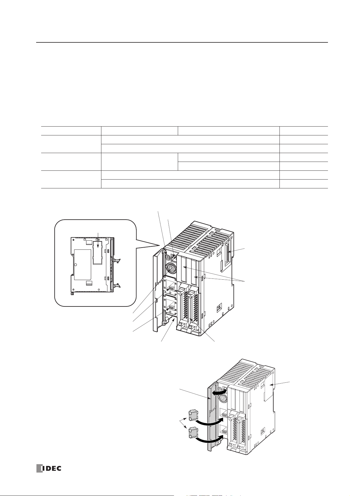
2: MODULE SPECIFICATIONS
« FC4A MICROSMART USER’S MANUAL » 2-11
CPU Modules (Slim Type)
Slim type CPU modules are available in 20- and 40-I/O types. The 20-I/O type has 12 input and 8 output terminals, and the
40-I/O type has 24 input and 16 output terminals. The FC4A-D20RK1 and FC4A-D20RS1 have 2 transistor outputs used
for high-speed outputs and pulse outputs in addition to 10 relay outputs. Every slim type CPU module has communication
port 1 for RS232C communication, and can mount an optional RS232C or RS485 communication module for 1:N computer link, modem communication, and data link communication. The HMI base module can also be mounted to install an
optional HMI module and a communication adapter. Every slim type CPU module has two cartridge connectors to install
an optional memory cartridge and a clock cartridge.
CPU Module Type Numbers (Slim Type)
Parts Description (Slim Type)
I/O Points Output Type High-speed Transistor Output (Q0 & Q1) Type No.
20 (12 in / 8 out)
Transistor Sink Output 0.3A FC4A-D20K3
Transistor Source Output 0.3A FC4A-D20S3
20 (12 in / 8 out)
Relay Output
240V AC/30V DC, 2A
Sink Output 0.3A FC4A-D20RK1
Source Output 0.3A FC4A-D20RS1
40 (24 in / 16 out)
Transistor Sink Output 0.3A FC4A-D40K3
Transistor Source Output 0.3A FC4A-D40S3
(3) Expansion Connector
(4) Power LED (PWR)
(5) Run LED (RUN)
(6) Error LED (ERR)
(7) Status LED (STAT)
(8) Input LED (DC.IN)
(9) Output LED (Tr.OUT or Ry.OUT)
(12) Port 1
(10) Analog Potentiometer
Side View
(14) Cartridge Connector 2
(1) Power Supply Terminals (2) I/O Terminals
(16) Hinged Lid
(18) Expansion
Connector
Seal
These figures illustrate the 40-I/O
type CPU module.
Functions of each part are described
on the following page.
(17) Dummy Cartridges
(15) Communication Connector
(11) Analog Voltage Input Connector
(13) Cartridge Connector 1
Page 32
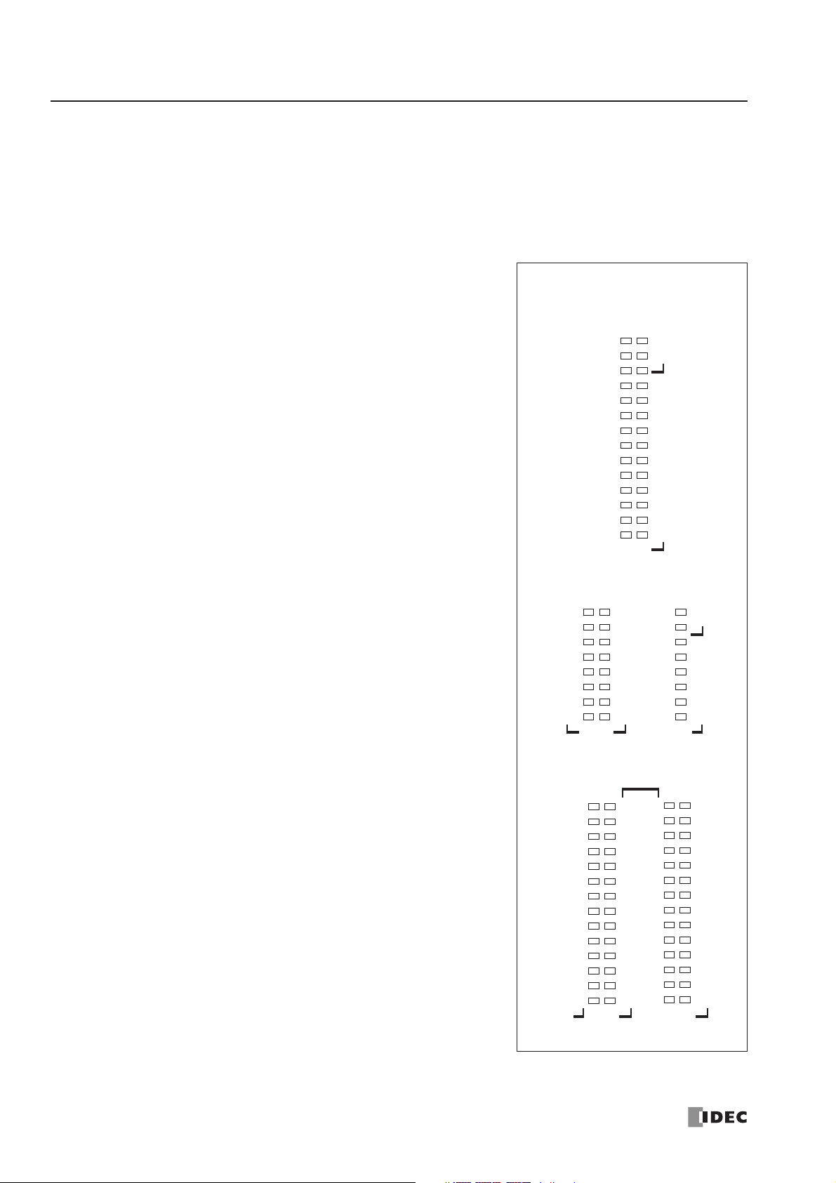
2: MODULE SPECIFICATIONS
2-12 « FC4A MICROSMART USER’S MANUAL »
(1) Power Supply Terminals
Connect power supply to these terminals. Power voltage 24V DC. See page 3-17.
(2) I/O Terminals
For connecting input and output signals. The input terminals accept both sink and source 24V DC input signals. Transistor and relay output types are available. Transistor output type has MIL connectors and relay output type has removable screw connectors.
(3) Expansion Connector
For connecting digital and analog I/O modules.
(4) Power LED (PWR)
Turns on when power is supplied to the CPU module.
(5) Run LED (RUN)
Turns on when the CPU module is executing the user program.
(6) Error LED (ERR)
Turns on when an error occurs in the CPU module.
(7) Status LED (STAT)
The status LED can be turned on or off using the user program to
indicate a specified status.
(8) Input LED (IN)
Turns on when a corresponding input is on.
(9) Output LED (Tr.OUT or Ry.OUT)
Turns on when a corresponding output is on.
(10) Analog Potentiometer
Sets a value of 0 through 255 to a special data register. All slim
type CPU modules have one potentiometer, which can be used to
set a preset value for an analog timer.
(11) Analog Voltage Input Connector
For connecting an analog voltage source of 0 through 10V DC. The
analog voltage is converted to a value of 0 through 255 and stored
to a special data register.
(12) Port 1 (RS232C)
For connecting a computer to download a user program and monitor the PLC operation on a computer using WindLDR.
(13) Cartridge Connector 1
For connecting an optional memory cartridge or clock cartridge.
(14) Cartridge Connector 2
For connecting an optional memory cartridge or clock cartridge.
(15) Communication Connector
For connecting an optional communication module or HMI base
module. Remove the connector cover before connecting a module.
(16) Hinged Lid
Open the lid to gain access to the port 1, cartridge connectors 1 and
2, analog potentiometer, and analog voltage input connector.
(17) Dummy Cartridges
Remove the dummy cartridge when using an optional memory cartridge or clock cartridge.
(18) Expansion Connector Seal
Remove the expansion connector seal when connecting a digital I/O or analog I/O module.
20-I/O Type (Transistor Output)
LED Indicators
PWR
RUN
ERR
STAT
0
1
2
3
4
5
6
7
10
11
0
1
2
3
4
5
6
7
12
13
DC.
IN
Tr.OUT
20-I/O Type (Relay Output)
PWR
RUN
ERR
STAT
0
1
2
3
DC.IN
4
5
6
7
10
11
12
13
Ry.OUT
0
1
2
3
4
5
6
7
Tr.
OUT
40-I/O Type (Transistor Output)
DC.IN
PWR
RUN
ERR
STAT
10
11
DC.IN
14
12
15
13
16
17
0
1
2
3
4
5
6
7
Tr.OUT Tr.OUT
20
21
22
0
23
1
24
2
25
3
26
4
27
5
6
7
10
11
12
13
14
15
16
17
Page 33

2: MODULE SPECIFICATIONS
« FC4A MICROSMART USER’S MANUAL » 2-13
General Specifications (Slim Type CPU Module)
Normal Operating Conditions
Power Supply
Note: The maximum number of relay outputs that can be turned on simultaneously is 96 points including relay outputs on
the CPU module.
CPU Module
FC4A-D20K3
FC4A-D20S3
FC4A-D20RK1
FC4A-D20RS1
FC4A-D40K3
FC4A-D40S3
Operating Temperature 0 to 55°C (operating ambient temperature)
Storage Temperature –25 to +70°C
Relative Humidity 10 to 95% (non-condensing)
Pollution Degree 2 (IEC 60664-1)
Degree of Protection IP20 (IEC 60529)
Corrosion Immunity Atmosphere free from corrosive gases
Altitude
Operation: 0 to 2,000m (0 to 6,565 feet)
Transport: 0 to 3,000m (0 to 9,840 feet)
Vibration Resistance
When mounted on a DIN rail or panel surface:
5 to 9 Hz amplitude 3.5 mm, 9 to 150 Hz acceleration 9.8 m/s
2
(1G)
2 hours per axis on each of three mutually perpendicular axes (IEC 61131-2)
Shock Resistance
147 m/s
2
(15G), 11 ms duration, 3 shocks per axis on three mutually perpendicular
axes (IEC 61131-2)
ESD Immunity Contact discharge: ±6 kV, Air discharge: ±8 kV (IEC 61000-4-2)
Weight 140g 185g 180g
Rated Power Voltage 24V DC
Allowable Voltage Range 20.4 to 26.4V DC (including ripple)
Maximum Input Current 560 mA (26.4V DC) 700 mA (26.4V DC) 700 mA (26.4V DC)
Maximum Power Consumption
CPU module + 7 I/O modules
14W (26.4V DC) 17W (26.4V DC) 17W (26.4V DC)
Allowable Momentary Power
Interruption
10 ms (at 24V DC)
Dielectric Strength
Between power and terminals: 500V AC, 1 minute
Between I/O and terminals: 1,500V AC, 1 minute
Insulation Resistance
Between power and terminals: 10 MΩ minimum (500V DC megger)
Between I/O and terminals: 10 MΩ minimum (500V DC megger)
Noise Resistance
DC power terminals: 1.0 kV, 50 nsec to 1 µs
I/O terminals (coupling clamp): 1.5 kV, 50 nsec to 1 µs
Inrush Current 50A maximum (24V DC)
Grounding Wire UL1015 AWG22, UL1007 AWG18
Power Supply Wire UL1015 AWG22, UL1007 AWG18
Effect of Improper Power
Supply Connection
Reverse polarity: No operation, no damage
Improper voltage or frequency: Permanent damage may be caused
Improper lead connection: Permanent damage may be caused
Page 34

2: MODULE SPECIFICATIONS
2-14 « FC4A MICROSMART USER’S MANUAL »
Function Specifications (Slim Type CPU Module)
CPU Module Specifications
Note 1: When using a 64KB memory cartridge and WindLDR ver. 4.2 or higher.
Note 2: When using a CPU module with system program ver. 201 or higher and WindLDR ver. 4.2 or higher.
System Statuses at Stop, Reset, and Restart
Note: All expansion data registers are keep types. AS-Inter face operands (M1300-M1977 and D1700-D1999) remain
unchanged when the reset input is turned on.
CPU Module
FC4A-D20K3
FC4A-D20S3
FC4A-D20RK1
FC4A-D20RS1
FC4A-D40K3
FC4A-D40S3
Program Capacity
27,000 bytes
(4,500 steps)
31,200 bytes (5,200 steps)
64,500 bytes (10,750 steps) (Note 1, Note 2)
Expandable I/O Modules 7 modules
I/O Points
Input 12
Expansion: 128
12
Expansion: 224
24
Expansion: 224
Output 8816
User Program Storage EEPROM
RAM Backup
Backup Duration Approx. 30 days (typical) at 25°C after backup battery fully charged
Backup Data Internal relay, shift register, counter, data register, expansion data register
Battery Lithium secondar y batter y
Charging Time Approx. 24 hours for charging from 0% to 90% of full charge at 25°C
Battery Life Approx. 1000 cycles of discharging down to 10% and full charging
Replaceability Not possible to replace battery
Control System Stored program system
Instruction Words
35 basic
53 advanced
35 basic
72 advanced
Processing
Time
Basic instruction 1.65 ms (1000 steps) See page A-1.
END processing
0.64 ms (not including expansion I/O service, clock function processing, data
link processing, and interrupt processing) See page A-2.
Internal Relay 1024 1024 + 560 for AS-Interface operands (Note 2)
Shift Register 128
Data Register 1300 1300 + 300 for AS-Inter face operands (Note 2)
Expansion Data Register — 6,000
Counter 100 (adding, dual pulse reversible, up/down selection reversible)
Timer 100 (1-sec, 100-ms, 10-ms, 1-ms)
Input Filter 3 to 15 ms (selectable in increments of 1 ms)
Catch Input
Interrupt Input
Four inputs (I2 through I5) can be designated as catch inputs or interrupt inputs
Minimum turn on pulse width: 40 µs maximum
Minimum turn off pulse width: 150 µs maximum
Self-diagnostic Function
Power failure, watchdog timer, data link connection, user program EEPROM sum
check, timer/counter preset value sum check, user program RAM sum check,
keep data, user program syntax, user program writing, CPU module, clock IC, I/O
bus initialize, user program execution
Start/Stop Method
Turning power on and off
Start/stop command in WindLDR
Turning start control special internal relay M8000 on and of f
Turning designated stop or reset input off and on
Mode Output
Internal Relay, Shift Register, Counter,
Data Register, Expansion Data Register
Timer Current Value
Keep Type Clear Type
Run Operating Operating Operating Operating
Stop (Stop input ON) OFF Unchanged Unchanged Unchanged
Reset (Reset input ON) OFF OFF/Reset to zero OFF/Reset to zero Reset to zero
Restart Unchanged Unchanged OFF/Reset to zero Reset to preset
Page 35

2: MODULE SPECIFICATIONS
« FC4A MICROSMART USER’S MANUAL » 2-15
Communication Function
Note 1: RS485 user communication is available on upgraded CPU modules only, see page 17-1.
Note 2: Recommended cable for RS485: Twisted-pair shielded cable with a minimum core wire of 0.3 mm
2
.
Conductor resistance 85 Ω/km maximum, shield resistance 20 Ω/km maximum.
Built-in Functions
Memory Cartridge (Option)
Clock Cartridge (Option)
Communication Port Port 1 (RS232C)
Port 2 (RS232C)
Communication Module
Communication Adapter
Port 2 (RS485)
Communication Module
Communication Adapter
Standards EIA RS232C EIA RS232C EIA RS485
Maximum Baud Rate 19,200 bps 19,200 bps
Computer link: 19,200 bps
User comm.: 19,200 bps
Data link: 38,400 bps
Maintenance Communication
(Computer Link)
Possible Possible Possible
User Communication Possible Possible Possible (Note 1)
Modem Communication Not possible Possible Not possible
Data Link Communication Not possible Not possible Possible
Quantity of Slave Stations —— 31
Maximum Cable Length Special cable Special cable 200m (Note 2)
Isolation between Internal Circuit
and Communication Port
Not isolated Not isolated Not isolated
High-speed Counter
Maximum Counting Frequency
and High-speed Counter Points
Total 4 points
Single/two-phase selectable: 20 kHz (2 points)
Single-phase: 5 kHz (2 points)
Counting Range 0 to 65535 (16 bits)
Operation Mode Rotar y encoder mode and adding counter mode
Analog Potentiometer
Quantity 1 point
Data Range 0 to 255
Analog Voltage Input
Quantity 1 point
Input Voltage Range 0 to 10V DC
Input Impedance Approx. 100 kΩ
Data Range 0 to 255
Pulse Output
Quantity 2 points
Maximum Frequency 20 kHz
Memory Type EEPROM
Accessible Memory Capacity 32 KB or 64 KB (64KB cartridge is for upgraded CPU modules only, see page 2-65)
Hardware for Storing Data CPU module
Software for Storing Data WindLDR
Quantity of Stored Programs One user program can be stored on one memor y cartridge.
Program Execution Priority
When a memory cartridge is installed, the user program on the memory cartridge is
executed.
Accuracy ±30 sec/month (typical) at 25°C
Backup Duration Approx. 30 days (typical) at 25°C after backup battery fully charged
Battery Lithium secondary battery
Charging Time Approx. 10 hours for charging from 0% to 90% of full charge
Battery Life Approx. 100 recharge cycles after discharging down to 10% of full charge
Replaceability Not possible to replace battery
Page 36

2: MODULE SPECIFICATIONS
2-16 « FC4A MICROSMART USER’S MANUAL »
DC Input Specifications (Slim Type CPU Module)
CPU Module
FC4A-D20K3
FC4A-D20S3
FC4A-D20RK1
FC4A-D20RS1
FC4A-D40K3
FC4A-D40S3
Input Points and Common Lines
12 points
in 1 common line
12 points
in 1 common line
24 points
in 2 common lines
Ter minal Arrangement See CPU Module Terminal Arrangement on pages 2-19 through 2-22.
Rated Input Voltage 24V DC sink/source input signal
Input Voltage Range 20.4 to 26.4V DC
Rated Input Current
I0, I1, I6, I7: 5 mA/point (24V DC)
I2 to I5, I10 to I27: 7 mA/point (24V DC)
Input Impedance
I0, I1, I6, I7: 5.7 kΩ
I2 to I5, I10 to I27: 3.4 kΩ
Turn ON Time
I0 to I7: 35 µs + filter value
I10 to I27: 40 µs + filter value
Turn OFF Time
I0, I1, I6, I7: 45 µs + filter value
I2 to I5, I10 to I27: 150 µs + filter value
Isolation
Between input terminals: Not isolated
Internal circuit: Photocoupler isolated
Input Type Type 1 (IEC 61131)
External Load for I/O Interconnection Not needed
Signal Determination Method Static
Effect of Improper Input Connection
Both sinking and sourcing input signals can be connected. If any input
exceeding the rated value is applied, permanent damage may be caused.
Cable Length 3m (9.84 ft.) in compliance with electromagnetic immunity
Connector on Mother Board
FL26A2MA
(Oki Electric Cable)
MC1.5/13-G-3.81BK
(Phoenix Contact)
FL26A2MA
(Oki Electric Cable)
Connector Insertion/Removal Durability 100 times minimum
Input Operating Range
The input operating range of the Type 1
(IEC 61131-2) input module is shown
below:
Inputs I0, I1, I6, and I7
26.4
24
15
5
Input Voltage (V DC)
0
1.2 12.4
Input Current (mA)
Inputs I2 to I5 and I10 to I27
26.4
24
15
5
Input Voltage (V DC)
0
1.2 7.7
Input Current (mA)
11.36.5
ON Area
Transition
Area
OFF Area
ON Area
Transition
Area
OFF Area
74.2
Input Internal Circuit
Inputs I0, I1, I6, and I7 Inputs I2 to I5 and I10 to I27
Input
COM
4.7 kΩ
Input
COM
Internal Circuit
3.3 kΩ
I/O Usage Limits
When using the FC4A-D20K3/S3 at an ambient temperature of 55°C in the
normal mounting direction, limit the inputs and outputs, respectively, which
turn on simultaneously along line (1).
When using the FC4A-D40K3/S3, limit the inputs and outputs, respectively,
which turn on simultaneously on each connector along line (2).
26.4
24.0
(2) 55°C
(1) 55°C
Input Voltage (V DC)
0
I/O Simultaneous ON Ratio (%)
(3) 40°C
50
60 70 800
100
When using at 40°C, all I/Os can
be turned on simultaneously at
26.4V DC as indicated with line (3).
When using the FC4A-D20RK1/
RS1, all I/Os can be turned on
simultaneously at 55°C, input voltage 26.4V DC.
Internal Circuit
Page 37

2: MODULE SPECIFICATIONS
« FC4A MICROSMART USER’S MANUAL » 2-17
Transistor Sink and Source Output Specifications (Slim Type CPU Module)
Output Internal Circuit
CPU Module
FC4A-D20K3
FC4A-D20RK1
FC4A-D40K3
FC4A-D20S3
FC4A-D20RS1
FC4A-D40S3
Output Type Sink output Source output
Output Points and Common Lines
FC4A-D20K3/S3: 8 points in 1 common line
FC4A-D20RK1/RS1: 2 points in 1 common line
FC4A-D40K3/S3: 16 points in 2 common lines
Ter minal Arrangement See CPU Module Terminal Arrangement on pages 2-19 through 2-22.
Rated Load Voltage 24V DC
Operating Load Voltage Range 20.4 to 28.8V DC
Rated Load Current 0.3A per output point
Maximum Load Current 1A per common line
Voltage Drop (ON Voltage) 1V maximum (voltage between COM and output terminals when output is on)
Inrush Current 1A maximum
Leakage Current 0.1 mA maximum
Clamping Voltage 39V±1V
Maximum Lamp Load 8W
Inductive Load L/R = 10 ms (28.8V DC, 1 Hz)
External Current Draw
100 mA maximum, 24V DC
(power voltage at the +V terminal)
100 mA maximum, 24V DC
(power voltage at the –V terminal)
Isolation
Between output terminal and internal circuit: Photocoupler isolated
Between output terminals: Not isolated
Connector on Mother Board
FC4A-D20K3/S3: FL26A2MA (Oki Electric Cable)
FC4A-D20RK1/RS1: MC1.5/16-G-3.81BK (Phoenix Contact)
FC4A-D40K3/S3: FL26A2MA (Oki Electric Cable)
Connector Insertion/Removal Durability 100 times minimum
Output Delay
Turn ON Time
Q0, Q1: 5 µs maximum
Q2 to Q17 300 µs maximum
Turn OFF Time
Q0, Q1: 5 µs maximum
Q2 to Q17 300 µs maximum
FC4A-D20K3, -D20RK1, and -D40K3 (Sink Output)
Internal Circuit
FC4A-D20S3, -D20RS1, and -D40S3 (Source Output)
+V
Output
Internal Circuit
COM(–)
COM(+)
Output
–V
Page 38

2: MODULE SPECIFICATIONS
2-18 « FC4A MICROSMART USER’S MANUAL »
Relay Output Specifications (Slim Type CPU Module)
Output Delay
CPU Module FC4A-D20RK1 FC4A-D20RS1
No. of Outputs 8 points including 2 transistor output points
Output Points per Common Line
COM0 (2 points transistor sink output) (2 points transistor source output)
COM1 3 NO contacts
COM2 2 NO contacts
COM3 1 NO contact
Ter minal Arrangement See CPU Module Terminal Arrangement on page 2-20.
Maximum Load Current
2A per point
8A per common line
Minimum Switching Load 0.1 mA/0.1V DC (reference value)
Initial Contact Resistance 30 mΩ maximum
Electrical Life 100,000 operations minimum (rated load 1,800 operations/hour)
Mechanical Life 20,000,000 operations minimum (no load 18,000 operations/hour)
Rated Load (resistive/inductive) 240V AC/2A, 30V DC/2A
Dielectric Strength
Between output and terminals: 1,500V AC, 1 minute
Between output terminal and internal circuit: 1,500V AC, 1 minute
Between output terminals (COMs): 1,500V AC, 1 minute
Connector on Mother Board MC1.5/16-G-3.81BK (Phoenix Contact)
Connector Insertion/Removal Durability 100 times minimum
Contact Protection Circuit for Relay Output See page 3-15.
Command
Output Relay Status
ON
OFF
ON
OFF
OFF delay: 10 ms maximum
Chatter: 6 ms maximum
ON delay: 6 ms maximum
Page 39
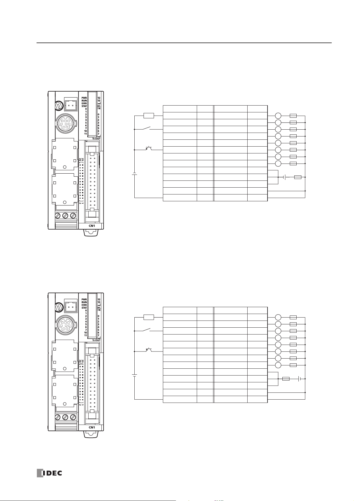
2: MODULE SPECIFICATIONS
« FC4A MICROSMART USER’S MANUAL » 2-19
CPU Module Terminal Arrangement and I/O Wiring Diagrams (Slim Type)
FC4A-D20K3 (20-I/O Transistor Sink Output Type CPU Module)
Applicable Connector: FC4A-PMC26P (not supplied with the CPU module)
FC4A-D20S3 (20-I/O Transistor Source Output Type CPU Module)
Applicable Connector: FC4A-PMC26P (not supplied with the CPU module)
Ter minal No. Input Terminal No. Output
26 I0 25 Q0
24 I1 23 Q1
22 I2 21 Q2
20 I3 19 Q3
18 I4 17 Q4
16 I5 15 Q5
14 I6 13 Q6
12 I7 11 Q7
10 I10 9 COM(–)
8 I11 7 COM(–)
6 I12 5 COM(–)
4 I13 3 +V
2 COM 1 +V
Source Input Wiring
Sink Output Wiring
2-wire Sensor
–
+
NPN
–
24V DC
+
• COM(–) terminals are connected together internally.
• COM and COM(–) terminals are not connected together internally.
• +V terminals are connected together internally.
• Connect a fuse appropriate for the load.
• For wiring precautions, see pages 3-13 through 3-17.
LoadLFuse
L
L
L
L
L
L
L
Fuse
+–
Sink Input Wiring
Source Output Wiring
2-wire Sensor
+
PNP
+
24V DC
–
• COM(+) terminals are connected together internally.
• COM and COM(+) terminals are not connected together internally.
• –V terminals are connected together internally.
Ter minal No. Input Terminal No. Output
–
26 I0 25 Q0
24 I1 23 Q1
22 I2 21 Q2
20 I3 19 Q3
18 I4 17 Q4
16 I5 15 Q5
14 I6 13 Q6
12 I7 11 Q7
10 I10 9 COM(+)
8 I11 7 COM(+)
6 I12 5 COM(+)
4 I13 3 –V
2 COM 1 –V
LoadLFuse
L
L
L
L
L
L
L
Fuse
• Connect a fuse appropriate for the load.
• For wiring precautions, see pages 3-13 through 3-17.
+–
Page 40
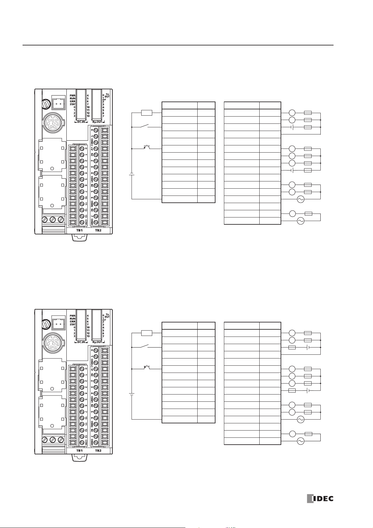
2: MODULE SPECIFICATIONS
2-20 « FC4A MICROSMART USER’S MANUAL »
FC4A-D20RK1 (20-I/O Relay and Transistor Sink High-speed Output Type CPU Module)
Applicable Terminal Blocks: TB1 (Left Side) FC4A-PMT13P (supplied with the CPU module)
TB2 (Right Side) FC4A-PMTK16P (supplied with the CPU module)
FC4A-D20RS1 (20-I/O Relay and Transistor Source High-speed Output Type CPU Module)
Applicable Terminal Blocks: TB1 (Left Side) FC4A-PMT13P (supplied with the CPU module)
TB2 (Right Side) FC4A-PMTS16P (supplied with the CPU module)
TB1 TB2
Ter minal No. Input Terminal No. Output
1I0 1 Q0
2I1 2 Q1
3I23COM(–)
4I3 4 +V
5I4 5 NC
6I5 6 Q2
7I6 7 Q3
8I7 8 Q4
9 I10 9 COM1
10 I11 10 NC
11 I12 11 Q5
12 I13 12 Q6
13 COM 13 COM2
14 NC
15 Q7
16 COM3
Source Input Wiring
Sink Output Wiring
2-wire Sensor
–
+
NPN
–
24V DC
+
LoadLFuse
L
+–
L
L
L
+–
L
L
L
• Outputs Q0 and Q1 are transistor sink outputs; others are relay outputs.
• COM, COM(–), COM1, COM2, and COM3 terminals are not connected
together internally.
• Connect a fuse appropriate for the load.
• For wiring precautions, see pages 3-13 through 3-17.
AC
AC
Sink Input Wiring
2-wire Sensor
–
+
PNP
+
24V DC
–
• Outputs Q0 and Q1 are transistor source outputs; others are relay outputs.
• COM, COM(+), COM1, COM2, and COM3 terminals are not connected
together internally.
• Connect a fuse appropriate for the load.
• For wiring precautions, see pages 3-13 through 3-17.
TB1 TB2
Ter minal No. Input Terminal No. Output
1I0 1 Q0
2I1 2 Q1
3I23COM(+)
4I3 4 –V
5I4 5 NC
6I5 6 Q2
7I6 7 Q3
8I7 8 Q4
9 I10 9 COM1
10 I11 10 NC
11 I12 11 Q5
12 I13 12 Q6
13 COM 13 COM2
14 NC
15 Q7
16 COM3
Source Output Wiring
LoadLFuse
L
+–
L
L
L
+–
L
L
AC
L
AC
Page 41
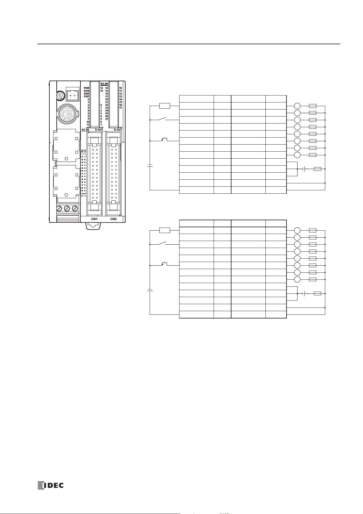
2: MODULE SPECIFICATIONS
« FC4A MICROSMART USER’S MANUAL » 2-21
FC4A-D40K3 (40-I/O Transistor Sink Output Type CPU Module)
Applicable Connector: FC4A-PMC26P (not supplied with the CPU module)
CN1
Ter minal No. Input Terminal No. Output
26 I0 25 Q0
24 I1 23 Q1
22 I2 21 Q2
20 I3 19 Q3
18 I4 17 Q4
16 I5 15 Q5
14 I6 13 Q6
12 I7 11 Q7
10 I10 9 COM(–)
8 I11 7 COM(–)
6 I12 5 COM(–)
4 I13 3 +V
2 COM 1 +V
Source Input Wiring
Sink Output Wiring
2-wire Sensor
–
+
NPN
–
24V DC
+
2-wire Sensor
–
NPN
–
24V DC
+
CN2
Ter minal No. Input Terminal No. Output
+
26 I14 25 Q10
24 I15 23 Q11
22 I16 21 Q12
20 I17 19 Q13
18 I20 17 Q14
16 I21 15 Q15
14 I22 13 Q16
12 I23 11 Q17
10 I24 9 COM(–)
8 I25 7 COM(–)
6 I26 5 COM(–)
4 I27 3 +V
2 COM 1 +V
LoadLFuse
L
L
L
L
L
L
L
Fuse
+–
LoadLFuse
L
L
L
L
L
L
L
Fuse
+–
• Terminals on CN1 and CN2 are not connected together internally.
• COM(–) terminals are connected together internally.
• COM and COM(–) terminals are not connected together internally.
• +V terminals are connected together internally.
• Connect a fuse appropriate for the load.
• For wiring precautions, see pages 3-13 through 3-17.
Page 42

2: MODULE SPECIFICATIONS
2-22 « FC4A MICROSMART USER’S MANUAL »
FC4A-D40S3 (40-I/O Transistor Source Output Type CPU Module)
Applicable Connector: FC4A-PMC26P (not supplied with the CPU module)
CN1
Ter minal No. Input Terminal No. Output
26 I0 25 Q0
24 I1 23 Q1
22 I2 21 Q2
20 I3 19 Q3
18 I4 17 Q4
16 I5 15 Q5
14 I6 13 Q6
12 I7 11 Q7
10 I10 9 COM(+)
8 I11 7 COM(+)
6 I12 5 COM(+)
4 I13 3 –V
2 COM 1 –V
Sink Input Wiring
+
–
+
–
Source Output Wiring
2-wire Sensor
24V DC
2-wire Sensor
+
24V DC
–
PNP
CN2
Ter minal No. Input Terminal No. Output
–
+
PNP
26 I14 25 Q10
24 I15 23 Q11
22 I16 21 Q12
20 I17 19 Q13
18 I20 17 Q14
16 I21 15 Q15
14 I22 13 Q16
12 I23 11 Q17
10 I24 9 COM(+)
8 I25 7 COM(+)
6 I26 5 COM(+)
4 I27 3 –V
2 COM 1 –V
LoadLFuse
L
L
L
L
L
L
L
Fuse
LoadLFuse
L
L
L
L
L
L
L
Fuse
+–
+–
• Terminals on CN1 and CN2 are not connected together internally.
• COM(+) terminals are connected together internally.
• COM and COM(+) terminals are not connected together internally.
• –V terminals are connected together internally.
• Connect a fuse appropriate for the load.
• For wiring precautions, see pages 3-13 through 3-17.
Page 43

2: MODULE SPECIFICATIONS
« FC4A MICROSMART USER’S MANUAL » 2-23
Input Modules
Digital input modules are available in 8-, 16-, and 32-point DC input modules and an 8-point AC input module with a
screw terminal block or plug-in connector for input wiring. All DC input modules accept both sink and source DC input
signals.
The input modules can be connected to the all-in-one 24-I/O type CPU module and all slim type CPU modules to expand
input terminals. The all-in-one 10- and 16-I/O type CPU modules cannot connect input modules.
Input Module Type Numbers
Parts Description
(1) Expansion Connector Connects to the CPU and other I/O modules.
(The all-in-one 10- and 16-I/O type CPU modules cannot be connected.)
(2) Module Label Indicates the input module Type No. and specifications.
(3) LED Indicator Turns on when a corresponding input is on.
(4) Terminal No. Indicates terminal numbers.
(5) Cable Terminal/Connector Five different terminal/connector styles are available for wiring.
Module Name 8-point DC Input 16-point DC Input 32-point DC Input 8-point AC Input
Screw Terminal FC4A-N08B1 FC4A-N16B1 — FC4A-N08A11
Connector — FC4A-N16B3 FC4A-N32B3 —
The above figures illustrate the 8-point DC input module.
(1) Expansion Connector
(2) Module Label
(3) LED Indicator
(4) Terminal No.
(5) Cable Terminal/Connector
Page 44

2: MODULE SPECIFICATIONS
2-24 « FC4A MICROSMART USER’S MANUAL »
DC Input Module Specifications
Type No. FC4A-N08B1 FC4A-N16B1 FC4A-N16B3 FC4A-N32B3
Input Points and Common Lines
8 points in 1
common line
16 points in 1
common line
16 points in 1
common line
32 points in 2
common lines
Ter minal Arrangement See Input Module Terminal Arrangement on pages 2-26 through 2-28.
Rated Input Voltage 24V DC sink/source input signal
Input Voltage Range 20.4 to 28.8V DC
Rated Input Current 7 mA/point (24V DC) 5 mA/point (24V DC)
Input Impedance 3.4 kΩ 4.4 kΩ
Turn ON Time (24V DC) 4 ms
Turn OFF Time (24V DC) 4 ms
Isolation
Between input terminals: Not isolated
Internal circuit: Photocoupler isolated
External Load for I/O Interconnection Not needed
Signal Determination Method Static
Effect of Improper Input Connection
Both sinking and sourcing input signals can be connected. If any input
exceeding the rated value is applied, permanent damage may be caused.
Cable Length 3m (9.84 ft.) in compliance with electromagnetic immunity
Connector on Mother Board MC1.5/10-G-3.81BK (Phoenix Contact) FL20A2MA (Oki Electric Cable)
Connector Insertion/Removal Durability 100 times minimum
Internal Current Draw
All Inputs ON
25 mA (5V DC)
0 mA (24V DC)
40 mA (5V DC)
0 mA (24V DC)
35 mA (5V DC)
0 mA (24V DC)
65 mA (5V DC)
0 mA (24V DC)
All Inputs OFF
5 mA (5V DC)
0 mA (24V DC)
5 mA (5V DC)
0 mA (24V DC)
5 mA (5V DC)
0 mA (24V DC)
10 mA (5V DC)
0 mA (24V DC)
Weight 85g 100g 65g 100g
I
it
I
nput Operating Range
The input operating range of the Type 1
(IEC 61131-2) input module is shown
below:
FC4A-N08B1 and FC4A-N16B1
28.8
24
ON Area
nput Internal Circu
FC4A-N08B1 and FC4A-N16B1 FC4A-N16B3 and FC4A-N32B3
Input
3.3 kΩ
Input
4.3 kΩ
COM
Internal Circuit
COM
Internal Circuit
Input Usage Limits
15
5
Input Voltage (V DC)
0
1.2 8.4
Input Current (mA)
FC4A-N16B3 and FC4A-N32B3
28.8
24
15
5
Input Voltage (V DC)
0
0.9 6.4
Input Current (mA)
7.04.2
5.33.2
Transition
Area
OFF Area
ON Area
Transition
Area
OFF Area
When using the FC4A-N16B1 at 55°C in the normal mounting direction, limit
the inputs which turn on simultaneously along line (1). At 45°C, all inputs
can be turned on simultaneously at 28.8V DC as indicated with line (2).
When using the FC4A-N16B3 or -N32B3 at 55°C, limit the inputs which turn
on simultaneously on each connector along line (3). At 30°C, all inputs can
be turned on simultaneously at 28.8V DC as indicated with line (4).
When using the FC4A-N08B1, all inputs can be turned on simultaneously at
55°C, input voltage 28.8V DC.
28.8
26.4
Input Voltage (V DC)
0
Input Simultaneous ON Ratio (%)
(2) 45°C
(1) 55°C
28.8
26.4
24.0
Input Voltage (V DC)
700
100
0
Input Simultaneous ON Ratio (%)
(4) 30°C
(3) 55°C
50
100
90
700
Page 45

2: MODULE SPECIFICATIONS
« FC4A MICROSMART USER’S MANUAL » 2-25
AC Input Module Specifications
Type No. FC4A-N08A11
Input Points and Common Lines 8 points in 2 common lines
Ter minal Arrangement See Input Module Terminal Arrangement on page 2-29.
Rated Input Voltage 100 to 120V AC (50/60 Hz)
Input Voltage Range 85 to 132V AC
Rated Input Current 17 mA/point (120V AC, 60 Hz)
Input Type AC input, Type 2 (IEC 61131-2)
Input Impedance 0.8 kΩ (60 Hz)
Turn ON Time 25 ms
Turn OFF Time 30 ms
Isolation
Between input terminals in the same common: Not isolated
Between input terminals in different commons: Isolated
Between input terminals and internal circuits: Photocoupler isolated
External Load for I/O Interconnection Not needed
Signal Determination Method Static
Effect of Improper Input Connection
If any input exceeding the rated value is applied, permanent damage may be
caused.
Connector on Mother Board MC1.5/11-G-3.81BK (Phoenix Contact)
Connector Insertion/Removal Durability 100 times minimum
Internal Current Draw
All Inputs ON
60 mA (5V DC)
0 mA (24V DC)
All Inputs OFF
30 mA (5V DC)
0 mA (24V DC)
Weight 80g
Input Operating Range
The input operating range of the Type 1, 2, 3 (IEC 61131-2)
input module is shown below:
FC4A-N08A11
132
100
79
74
Input Voltage (V AC)
20
0
1
5
24 17
Input Current (mA)
13
ON Area
Transition
Area
OFF Area
Input Internal Circuit
FC4A-N08A11
480 kΩ
Input
0.33 µF
COM
220Ω
Internal Circuit
Input Usage Limits
When using the FC4A-N08A11, all inputs can be
turned on simultaneously at 55°C, input voltage
132V AC.
132
120
102
Input Voltage (V AC)
0
Input Simultaneous ON Ratio (%)
55°C
500
100
Page 46

2: MODULE SPECIFICATIONS
2-26 « FC4A MICROSMART USER’S MANUAL »
DC Input Module Terminal Arrangement and Wiring Diagrams
FC4A-N08B1 (8-point DC Input Module) — Screw Terminal Type
Applicable Terminal Block: FC4A-PMT10P (supplied with the input module)
FC4A-N16B1 (16-point DC Input Module) — Screw Terminal Type
Applicable Terminal Block: FC4A-PMT10P (supplied with the input module)
DC.IN
0
1
2
3
4
5
6
7
Source Input Wiring
2-wire Sensor
–
+
Ter minal No. Input
0I0
1I1
2I2
Sink Input Wiring
2-wire Sensor
3I3
4I4
5I5
6I6
7I7
COM COM
+
–
01234567
–
24V DC
+
NPN
COM COM
• Two COM terminals are connected together internally.
• For input wiring precautions, see page 3-13.
COM COM
+
PNP
24V DC
Ter minal No. Input
–
0I0
1I1
2I2
3I3
4I4
5I5
6I6
7I7
COM COM
COM COM
DC.IN
0 1 2 3 4 5 6 7
COM COM
10 11 12 13 14 15 16 17
COM COM
0
1
2
3
4
5
6
7
10
11
12
13
14
15
16
17
Source Input Wiring
2-wire Sensor
–
+
Ter minal No. Input
0I0
1I1
2I2
3I3
NPN
4I4
5I5
6I6
7I7
COM COM
COM COM
–
+
10 I10
11 I11
12 I12
13 I13
14 I14
15 I15
16 I16
17 I17
–
24V DC
+
NPN
COM COM
COM COM
• Four COM terminals are connected together internally.
• For input wiring precautions, see page 3-13.
Sink Input Wiring
2-wire Sensor
–
+
PNP
–
+
PNP
+
24V DC
–
Ter minal No. Input
0I0
1I1
2I2
3I3
4I4
5I5
6I6
7I7
COM COM
COM COM
10 I10
11 I11
12 I12
13 I13
14 I14
15 I15
16 I16
17 I17
COM COM
COM COM
Page 47

2: MODULE SPECIFICATIONS
« FC4A MICROSMART USER’S MANUAL » 2-27
FC4A-N16B3 (16-point DC Input Module) — Connector Type
Applicable Connector: FC4A-PMC20P (not supplied with the input module)
• Two COM terminals are connected together internally.
•
Source Input Wiring
2-wire Sensor
–
24V DC
+
Sink Input Wiring
2-wire Sensor
+
24V DC
–
–
NPN
+
PNP
Ter minal No. Input Terminal No. Input
+
–
20 I0 19 I10
18 I1 17 I11
16 I2 15 I12
14 I3 13 I13
12 I4 11 I14
10 I5 9 I15
8I67I16
6I75I17
4 COM 3 COM
2NC1NC
Ter minal No. Input Terminal No. Input
20 I0 19 I10
18 I1 17 I11
16 I2 15 I12
14 I3 13 I13
12 I4 11 I14
10 I5 9 I15
8I67I16
6I75I17
4 COM 3 COM
2NC1NC
2-wire Sensor
–
+
NPN
–
24V DC
+
2-wire Sensor
–
+
PNP
+
24V DC
–
For input wiring precautions, see page 3-13.
Page 48
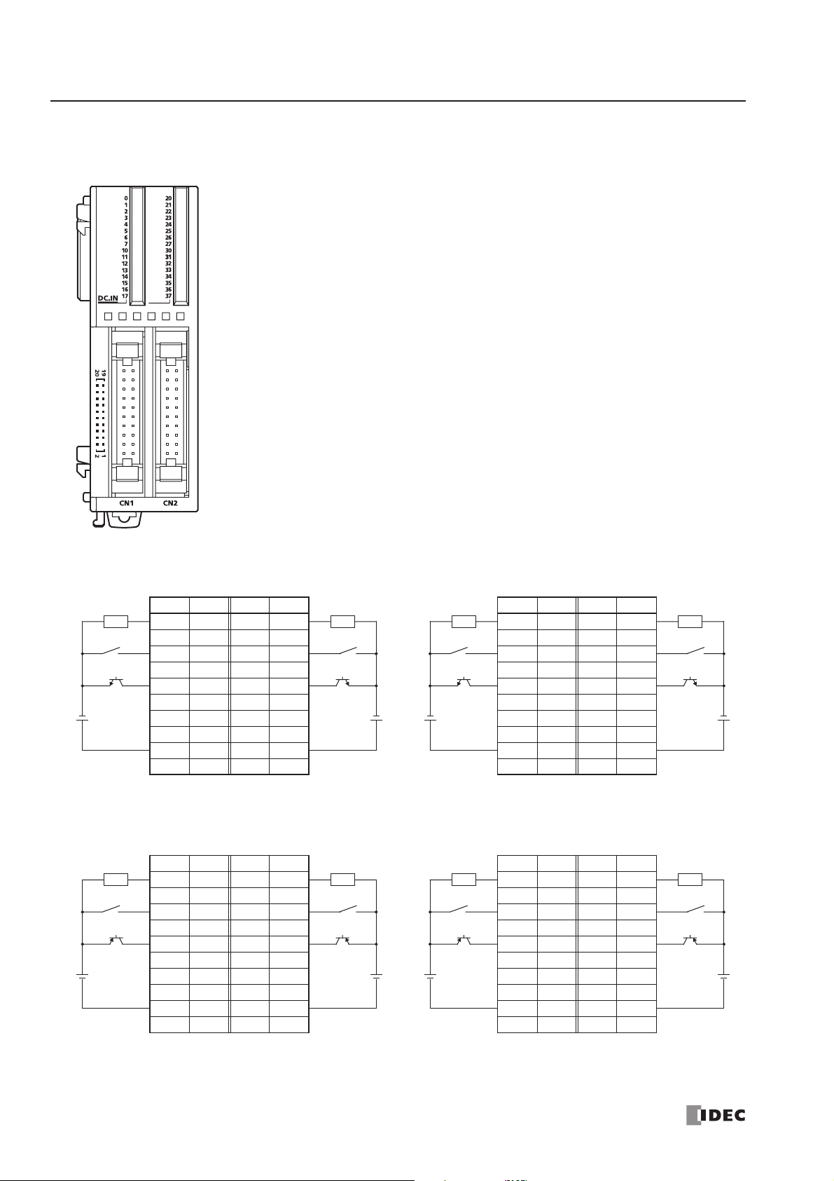
2: MODULE SPECIFICATIONS
2-28 « FC4A MICROSMART USER’S MANUAL »
FC4A-N32B3 (32-point DC Input Module) — Connector Type
Applicable Connector: FC4A-PMC20P (not supplied with the input module)
CN1
No. Input No. Input
20 I0 19 I10
18 I1 17 I11
16 I2 15 I12
14 I3 13 I13
12 I4 11 I14
10 I5 9 I15
8I67I16
6I75I17
4 COM0 3 COM0
2NC1NC
Source Input Wiring
• COM0 terminals are connected together internally.
• COM1 terminals are connected together internally.
• COM0 and COM1 terminals are not connected together internally.
• For input wiring precautions, see page 3-13.
2-wire Sensor
–
NPN
–
24V DC
+
Sink Input Wiring
2-wire Sensor
+
PNP
+
24V DC
–
+
CN1
No. Input No. Input
–
20 I0 19 I10
18 I1 17 I11
16 I2 15 I12
14 I3 13 I13
12 I4 11 I14
10 I5 9 I15
8I67I16
6I75I17
4 COM0 3 COM0
2NC1NC
2-wire Sensor
–
+
NPN
24V DC
2-wire Sensor
–
+
PNP
24V DC
CN2
2-wire Sensor
–
+
No. Input No. Input
20 I20 19 I30
2-wire Sensor
–
+
18 I21 17 I31
16 I22 15 I32
14 I23 13 I33
NPN
–
+
–
24V DC
+
12 I24 11 I34
10 I25 9 I35
8 I26 7 I36
6 I27 5 I37
NPN
24V DC
–
+
4 COM1 3 COM1
2NC1NC
CN2
2-wire Sensor
+
No. Input No. Input
–
20 I20 19 I30
2-wire Sensor
–
+
18 I21 17 I31
16 I22 15 I32
14 I23 13 I33
PNP
+
–
+
24V DC
–
12 I24 11 I34
10 I25 9 I35
8 I26 7 I36
6 I27 5 I37
PNP
24V DC
+
–
4 COM1 3 COM1
2NC1NC
Page 49

2: MODULE SPECIFICATIONS
« FC4A MICROSMART USER’S MANUAL » 2-29
AC Input Module Terminal Arrangement and Wiring Diagrams
FC4A-N08A11 (8-point AC Input Module) — Screw Terminal Type
Applicable Terminal Block: FC4A-PMT11P (supplied with the input module)
AC.IN
1023
COM0
NC 4 5 6
7 COM1
0
1
2
3
4
5
6
7
Ter minal No. Output
0I0
1I1
2I2
3I3
COM0 COM0
AC
NC NC
4I4
5I5
6I6
7I7
COM1 COM1
AC
• Two COM terminals are not connected together internally.
• For input wiring precautions, see page 3-13.
• Do not connect an external load to the input terminals.
Page 50
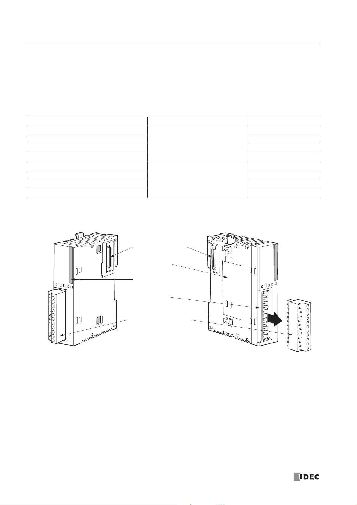
2: MODULE SPECIFICATIONS
2-30 « FC4A MICROSMART USER’S MANUAL »
Output Modules
Digital output modules are available in 8- and 16-point relay output modules, 8-, 16- and 32-point transistor sink output
modules, and 8-, 16- and 32-point transistor source output modules with a screw terminal block or plug-in connector for
output wiring.
The output modules can be connected to the all-in-one 24-I/O type CPU module and all slim type CPU modules to expand
output terminals. The all-in-one 10- and 16-I/O type CPU modules cannot connect output modules.
Output Module Type Numbers
Parts Description
(1) Expansion Connector Connects to the CPU and other I/O modules.
(The all-in-one 10- and 16-I/O type CPU modules cannot be connected.)
(2) Module Label Indicates the output module Type No. and specifications.
(3) LED Indicator Turns on when a corresponding output is on.
(4) Terminal No. Indicates terminal numbers.
(5) Cable Terminal/Connector Five different terminal/connector styles are available for wiring.
Module Name Terminal Type No.
8-point Relay Output
Removable Terminal Block
FC4A-R081
16-point Relay Output FC4A-R161
8-point Transistor Sink Output FC4A-T08K1
8-point Transistor Source Output FC4A-T08S1
16-point Transistor Sink Output
MIL Connector
FC4A-T16K3
16-point Transistor Source Output FC4A-T16S3
32-point Transistor Sink Output FC4A-T32K3
32-point Transistor Source Output FC4A-T32S3
The above figures illustrate the 8-point relay output module.
(1) Expansion Connector
(2) Module Label
(3) LED Indicator
(4) Terminal No.
(5) Cable Terminal/Connector
Page 51

2: MODULE SPECIFICATIONS
« FC4A MICROSMART USER’S MANUAL » 2-31
Relay Output Module Specifications
Note: When relay output modules are connected to the all-in-one 24-I/O type CPU module or any slim type CPU module, the
maximum number of relay outputs that can be turned on simultaneously, including the outputs on the CPU module, are
shown below.
Output Delay
Type No. FC4A-R081 FC4A-R161
Output Points and Common Lines 8 NO contacts in 2 common lines 16 NO contacts in 2 common lines
Ter minal Arrangement See Relay Output Module Terminal Arrangement on page 2-32.
Maximum Load Current
2A per point
7A per common line 8A per common line
Minimum Switching Load 0.1 mA/0.1V DC (reference value)
Initial Contact Resistance 30 mΩ maximum
Electrical Life 100,000 operations minimum (rated load 1,800 operations/hour)
Mechanical Life 20,000,000 operations minimum (no load 18,000 operations/hour)
Rated Load (resistive/inductive) 240V AC/2A, 30V DC/2A
Dielectric Strength
Between output and or terminals: 1,500V AC, 1 minute
Between output terminal and internal circuit: 1,500V AC, 1 minute
Between output terminals (COMs): 1,500V AC, 1 minute
Connector on Mother Board
MC1.5/11-G-3.81BK
(Phoenix Contact)
MC1.5/10-G-3.81BK
(Phoenix Contact)
Connector Insertion/Removal Durability 100 times minimum 100 times minimum
Internal Current Draw
All Outputs ON
30 mA (5V DC)
40 mA (24V DC)
45 mA (5V DC)
75 mA (24V DC)
All Outputs OFF
5 mA (5V DC)
0 mA (24V DC)
5 mA (5V DC)
0 mA (24V DC)
Weight 110g 145g
Contact Protection Circuit for Relay Output See page 3-15.
CPU Module Type All-in-One 24-I/O CPU Module Slim Type CPU Module
Maximum Relay Outputs Turning On Simultaneously 33 54
Command
Output Relay Status
ON
OFF
ON
OFF
OFF delay: 10 ms maximum
Chatter: 6 ms maximum
ON delay: 6 ms maximum
Page 52

2: MODULE SPECIFICATIONS
2-32 « FC4A MICROSMART USER’S MANUAL »
Relay Output Module Terminal Arrangement and Wiring Diagrams
FC4A-R081 (8-point Relay Output Module) — Screw Terminal Type
Applicable Terminal Block: FC4A-PMT11P (supplied with the output module)
FC4A-R161 (16-point Relay Output Module) — Screw Terminal Type
Applicable Terminal Block: FC4A-PMT10P (supplied with the output module)
Ry.OUT
1023
COM0
NC 456
0
1
2
3
4
5
6
7
+
–
Fuse
DC
Fuse
+
DC
–
–
+
Fuse
–
+
Fuse
DC
DC
Fuse
AC
Fuse
AC
Fuse
• COM0 and COM1 terminals are not connected together internally.
Load
• Connect a fuse appropriate for the load.
• For output wiring precautions, see page 3-14.
7 COM1
Ter minal No. Output
L
L
L
L
0Q0
1Q1
2Q2
3Q3
COM0 COM0
NC NC
L
L
L
L
4Q4
5Q5
6Q6
7Q7
COM1 COM1
Ry.OUT
0 1 2 3 4 5 6 7
COM0 COM0
10 11 12 13 14 15 16 17
COM1 COM1
0
1
2
3
4
5
6
7
10
11
12
13
14
15
16
17
Ter minal No. Output
0Q0
1Q1
2Q2
3Q3
4Q4
5Q5
6Q6
7Q7
+
–
Fuse
DC
–
+
Fuse
DC
Fuse
AC
Fuse
Load
L
L
L
L
L
L
L
L
COM0 COM0
COM0 COM0
10 Q10
11 Q11
12 Q12
13 Q13
14 Q14
15 Q15
16 Q16
17 Q17
+
–
Fuse
DC
–
+
Fuse
DC
Fuse
AC
L
L
L
L
L
L
L
L
COM1 COM1
COM1 COM1
• COM0 terminals are connected together internally.
• COM1 terminals are connected together internally.
• COM0 and COM1 terminals are not connected together internally.
• Connect a fuse appropriate for the load.
• For output wiring precautions, see page 3-14.
Page 53

2: MODULE SPECIFICATIONS
« FC4A MICROSMART USER’S MANUAL » 2-33
Transistor Sink Output Module Specifications
Output Internal Circuit
Type No. FC4A-T08K1 FC4A-T16K3 FC4A-T32K3
Output Type Transistor sink output
Output Points and Common Lines
8 points
in 1 common line
16 points
in 1 common line
32 points
in 2 common lines
Ter minal Arrangement
See Transistor Sink Output Module Terminal Arrangement on pages 2-34
and 2-35.
Rated Load Voltage 24V DC
Operating Load Voltage Range 20.4 to 28.8V DC
Rated Load Current 0.3A per output point 0.1A per output point
Maximum Load Current (at 28.8V DC)
0.3A per output point
3A per common line
0.1A per output point
1A per common line
Voltage Drop (ON Voltage) 1V maximum (voltage between COM and output terminals when output is on)
Inrush Current 1A maximum
Leakage Current 0.1 mA maximum
Clamping Voltage 39V±1V
Maximum Lamp Load 8W
Inductive Load L/R = 10 ms (28.8V DC, 1 Hz)
External Current Draw 100 mA maximum, 24V DC (power voltage at the +V terminal)
Isolation
Between output terminal and internal circuit: Photocoupler isolated
Between output terminals: Not isolated
Connector on Mother Board
MC1.5/10-G-3.81BK
(Phoenix Contact)
FL20A2MA (Oki Electric Cable)
Connector Insertion/Removal Durability 100 times minimum
Internal Current
Draw
All Outputs ON
10 mA (5V DC)
20 mA (24V DC)
10 mA (5V DC)
40 mA (24V DC)
20 mA (5V DC)
70 mA (24V DC)
All Outputs OFF
5 mA (5V DC)
0 mA (24V DC)
5 mA (5V DC)
0 mA (24V DC)
10 mA (5V DC)
0 mA (24V DC)
Output Delay
Turn ON time: 300 µs maximum
Turn OFF time: 300 µs maximum
Weight (approx.) 85g 70g 105g
Sink Output
Internal Circuit
+V
Output
COM(–)
Page 54

2: MODULE SPECIFICATIONS
2-34 « FC4A MICROSMART USER’S MANUAL »
Transistor Sink Output Module Terminal Arrangement and Wiring Diagrams
FC4A-T08K1 (8-point Transistor Sink Output Module) — Screw Terminal Type
Applicable Terminal Block: FC4A-PMT10P (supplied with the output module)
FC4A-T16K3 (16-point Transistor Sink Output Module) — Connector Type
Applicable Connector: FC4A-PMC20P (not supplied with the output module)
Tr.OUT
0
1
2
3
4
5
6
7
Fuse
Load
Ter minal No. Output
L
L
L
L
L
L
L
L
01234567
Fuse
+–
• Connect a fuse appropriate for the load.
• For output wiring precautions, see page 3-14.
COM(–)
+V
0Q0
1Q1
2Q2
3Q3
4Q4
5Q5
6Q6
7Q7
COM(–) COM(–)
+V +V
Fuse
Load
+–
Ter minal No. Output Terminal No. Output
L
L
L
L
L
L
L
L
20 Q0 19 Q10
18 Q1 17 Q11
16 Q2 15 Q12
14 Q3 13 Q13
12 Q4 11 Q14
10 Q5 9 Q15
8Q67Q16
6Q75Q17
4 COM(–) 3 COM(–)
2+V1+V
• COM(–) terminals are connected together internally.
• +V terminals are connected together internally.
• Connect a fuse appropriate for the load.
• For output wiring precautions, see page 3-14.
LoadLFuse
L
L
L
L
L
L
L
+–
Page 55
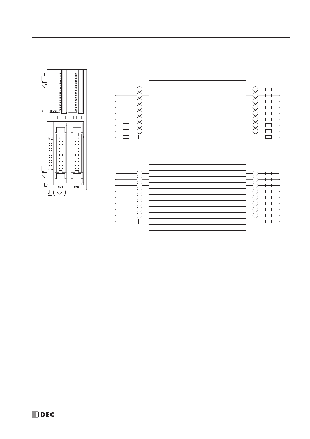
2: MODULE SPECIFICATIONS
« FC4A MICROSMART USER’S MANUAL » 2-35
FC4A-T32K3 (32-point Transistor Sink Output Module) — Connector Type
Applicable Connector: FC4A-PMC20P (not supplied with the output module)
• Terminals on CN1 and CN2 are not connected together internally.
CN1
Fuse
Fuse
Load
+–
Load
+–
Ter minal No. Output Terminal No. Output
L
L
L
L
L
L
L
L
L
L
L
L
L
L
L
L
20 Q0 19 Q10
18 Q1 17 Q11
16 Q2 15 Q12
14 Q3 13 Q13
12 Q4 11 Q14
10 Q5 9 Q15
8Q67Q16
6Q75Q17
4 COM0(–) 3 COM0(–)
2 +V0 1 +V0
CN2
Ter minal No. Output Terminal No. Output
20 Q20 19 Q30
18 Q21 17 Q31
16 Q22 15 Q32
14 Q23 13 Q33
12 Q24 11 Q34
10 Q25 9 Q35
8 Q26 7 Q36
6 Q27 5 Q37
4 COM1(–) 3 COM1(–)
2 +V1 1 +V1
LoadLFuse
L
L
L
L
L
L
L
+–
LoadLFuse
L
L
L
L
L
L
L
+–
• COM0(–) terminals are connected together internally.
• COM1(–) terminals are connected together internally.
• +V0 terminals are connected together internally.
• +V1 terminals are connected together internally.
• Connect a fuse appropriate for the load.
• For output wiring precautions, see page 3-14.
Page 56

2: MODULE SPECIFICATIONS
2-36 « FC4A MICROSMART USER’S MANUAL »
Transistor Source Output Module Specifications
Output Internal Circuit
Type No. FC4A-T08S1 FC4A-T16S3 FC4A-T32S3
Output Type Transistor source output
Output Points and Common Lines
8 points
in 1 common line
16 points
in 1 common line
32 points
in 2 common lines
Ter minal Arrangement
See Transistor Source Output Module Terminal Arrangement on pages 2-37
and 2-38.
Rated Load Voltage 24V DC
Operating Load Voltage Range 20.4 to 28.8V DC
Rated Load Current 0.3A per output point 0.1A per output point
Maximum Load Current (at 28.8V DC)
0.3A per output point
3A per common line
0.1A per output point
1A per common line
Voltage Drop (ON Voltage) 1V maximum (voltage between COM and output terminals when output is on)
Inrush Current 1A maximum
Leakage Current 0.1 mA maximum
Clamping Voltage 39V±1V
Maximum Lamp Load 8W
Inductive Load L/R = 10 ms (28.8V DC, 1 Hz)
External Current Draw 100 mA maximum, 24V DC (power voltage at the –V terminal)
Isolation
Between output terminal and internal circuit: Photocoupler isolated
Between output terminals: Not isolated
Connector on Mother Board
MC1.5/10-G-3.81BK
(Phoenix Contact)
FL20A2MA (Oki Electric Cable)
Connector Insertion/Removal Durability 100 times minimum
Internal Current
Draw
All Outputs ON
10 mA (5V DC)
20 mA (24V DC)
10 mA (5V DC)
40 mA (24V DC)
20 mA (5V DC)
70 mA (24V DC)
All Outputs OFF
5 mA (5V DC)
0 mA (24V DC)
5 mA (5V DC)
0 mA (24V DC)
10 mA (5V DC)
0 mA (24V DC)
Output Delay
Turn ON time: 300 µs maximum
Turn OFF time: 300 µs maximum
Weight (approx.) 85g 70g 105g
Source Output
COM(+)
Output
Internal Circuit
–V
Page 57

2: MODULE SPECIFICATIONS
« FC4A MICROSMART USER’S MANUAL » 2-37
Transistor Source Output Module Terminal Arrangement and Wiring Diagrams
FC4A-T08S1 (8-point Transistor Source Output Module) — Screw Terminal Type
Applicable Terminal Block: FC4A-PMT10P (supplied with the output module)
FC4A-T16S3 (16-point Transistor Source Output Module) — Connector Type
Applicable Connector: FC4A-PMC20P (not supplied with the output module)
Tr.OUT
0
1
2
3
4
5
6
7
Load
Ter minal No. Output
L
L
L
L
L
L
L
01234567
Fuse
+–
L
• Connect a fuse appropriate for the load.
• For output wiring precautions, see page 3-14.
COM(+)
–V
0Q0
1Q1
2Q2
3Q3
4Q4
5Q5
6Q6
7Q7
COM(+) COM(+)
–V –V
Fuse
Load
+–
Ter minal No. Output Terminal No. Output
L
L
L
L
L
L
L
L
20 Q0 19 Q10
18 Q1 17 Q11
16 Q2 15 Q12
14 Q3 13 Q13
12 Q4 11 Q14
10 Q5 9 Q15
8Q67Q16
6Q75Q17
4 COM(+) 3 COM(+)
2–V1–V
• COM(+) terminals are connected together internally.
• –V terminals are connected together internally.
• Connect a fuse appropriate for the load.
• For output wiring precautions, see page 3-14.
LoadLFuse
L
L
L
L
L
L
L
+–
Page 58
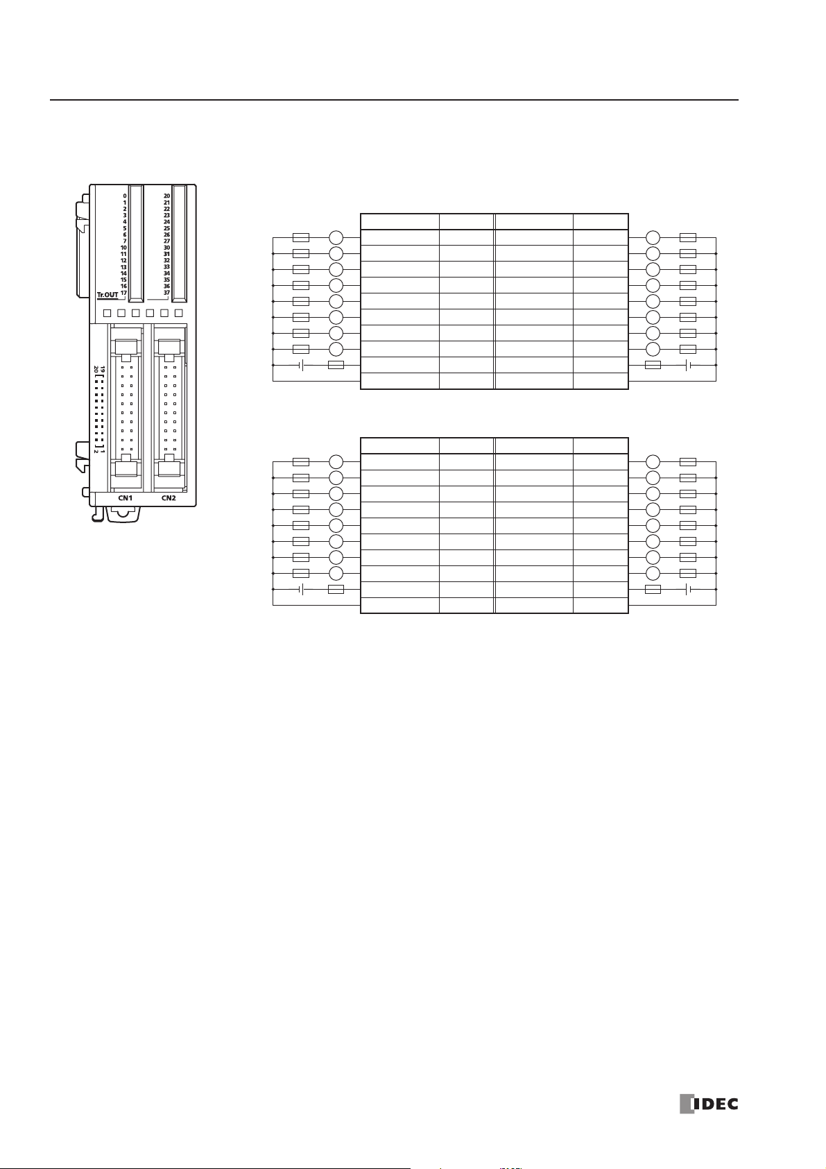
2: MODULE SPECIFICATIONS
2-38 « FC4A MICROSMART USER’S MANUAL »
FC4A-T32S3 (32-point Transistor Source Output Module) — Connector Type
Applicable Connector: FC4A-PMC20P (not supplied with the output module)
• Terminals on CN1 and CN2 are not
CN1
Fuse
Fuse
Load
+–
Load
+–
Ter minal No. Output Terminal No. Output
L
L
L
L
L
L
L
L
L
L
L
L
L
L
L
L
20 Q0 19 Q10
18 Q1 17 Q11
16 Q2 15 Q12
14 Q3 13 Q13
12 Q4 11 Q14
10 Q5 9 Q15
8Q67Q16
6Q75Q17
4 COM0(+) 3 COM0(+)
2 –V0 1 –V0
CN2
Ter minal No. Output Terminal No. Output
20 Q20 19 Q30
18 Q21 17 Q31
16 Q22 15 Q32
14 Q23 13 Q33
12 Q24 11 Q34
10 Q25 9 Q35
8 Q26 7 Q36
6 Q27 5 Q37
4 COM1(+) 3 COM1(+)
2 –V1 1 –V1
LoadLFuse
L
L
L
L
L
L
L
+–
LoadLFuse
L
L
L
L
L
L
L
+–
• COM0(+) terminals are connected together internally.
• COM1(+) terminals are connected together internally.
• –V0 terminals are connected together internally.
• –V1 terminals are connected together internally.
• Connect a fuse appropriate for the load.
• For output wiring precautions, see page 3-14.
connected together internally.
Page 59
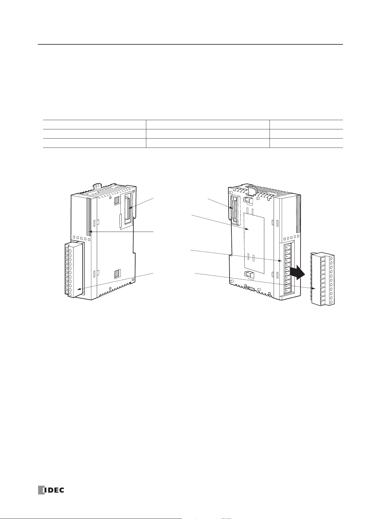
2: MODULE SPECIFICATIONS
« FC4A MICROSMART USER’S MANUAL » 2-39
Mixed I/O Modules
The 4-in/4-out mixed I/O module has 4-point DC sink/source inputs and 4-point relay outputs, with a screw terminal block
for I/O wiring. The 16-in/8-out mixed I/O module has 16-point DC sink/source inputs and 8-point relay outputs, with a
wire-clamp terminal block for I/O wiring.
The mixed I/O modules can be connected to the all-in-one 24-I/O type CPU module and all slim type CPU modules to
expand input and output terminals. The all-in-one 10- and 16-I/O type CPU modules cannot connect mixed I/O modules.
Mixed I/O Module Type Numbers
Parts Description
(1) Expansion Connector Connects to the CPU and other I/O modules.
(The all-in-one 10- and 16-I/O type CPU modules cannot be connected.)
(2) Module Label Indicates the mixed I/O module Type No. and specifications.
(3) LED Indicator Turns on when a corresponding input or output is on.
(4) Terminal No. Indicates terminal numbers.
(5) Cable Terminal Two different terminal styles are available for wiring.
Module Name Terminal Type No.
4-in/4-out Mixed I/O Module Removable Terminal Block FC4A-M08BR1
16-in/8-out Mixed I/O Module Non-removable Wire-clamp Terminal Block FC4A-M24BR2
(1) Expansion Connector
(2) Module Label
(3) LED Indicator
(4) Terminal No.
(5) Cable Terminal
The above figures illustrate the 4-in/4-out mixed I/O module.
Page 60

2: MODULE SPECIFICATIONS
2-40 « FC4A MICROSMART USER’S MANUAL »
Mixed I/O Module Specifications
DC Input Specifications (Mixed I/O Module)
Type No. FC4A-M08BR1 FC4A-M24BR2
I/O Points
4 inputs in 1 common line
4 outputs in 1 common line
16 inputs in 1 common line
8 outputs in 2 common lines
Ter minal Arrangement See Mixed I/O Module Terminal Arrangement on pages 2-41 and 2-42.
Connector on Mother Board
MC1.5/11-G-3.81BK
(Phoenix Contact)
Input: F6018-17P (Fujicon)
Output: F6018-11P (Fujicon)
Connector Insertion/Removal Durability 100 times minimum Not removable
Internal Current Draw
All I/Os ON
25 mA (5V DC)
20 mA (24V DC)
65 mA (5V DC)
45 mA (24V DC)
All I/Os OFF
5 mA (5V DC)
0 mA (24V DC)
10 mA (5V DC)
0 mA (24V DC)
Weight 95g 140g
Input Points and Common Line 4 points in 1 common line 16 points in 1 common line
Rated Input Voltage 24V DC sink/source input signal
Input Voltage Range 20.4 to 28.8V DC
Rated Input Current 7 mA/point (24V DC)
Input Impedance 3.4 kΩ
Turn ON Time 4 ms (24V DC)
Turn OFF Time 4 ms (24V DC)
Isolation
Between input terminals: Not isolated
Internal circuit: Photocoupler isolated
External Load for I/O Interconnection Not needed
Signal Determination Method Static
Effect of Improper Input Connection
Both sinking and sourcing input signals can be connected. If any input
exceeding the rated value is applied, permanent damage may be caused.
Cable Length 3m (9.84 ft.) in compliance with electromagnetic immunity
Input Operating Range
The input operating range of the Type 1 (IEC 61131-2)
input module is shown below:
I/O Usage Limits
When using the FC4A-M24BR2 at an ambient temperature of 55°C in the normal mounting direction, limit the
inputs and outputs, respectively, which turn on simulta-
28.8
24
15
5
Input Voltage (V DC)
0
1.2 8.4
Input Current (mA)
ON Area
Transition
Area
OFF Area
74.2
neously along line (1).
Input Voltage (V DC)
Input Internal Circuit
Input
COM
3.3 kΩ
Internal Circuit
When using at 45°C, all I/Os can be turned on simultaneously at input voltage 28.8V DC as indicated with line
(2).
When using the FC4A-M08BR1, all I/Os can be turned on
simultaneously at 55°C, input voltage 28.8V DC.
(2) 45°C
28.8
26.4
(1) 55°C
0
0
I/O Simultaneous ON Ratio (%)
80
100
Page 61

2: MODULE SPECIFICATIONS
« FC4A MICROSMART USER’S MANUAL » 2-41
Relay Output Specifications (Mixed I/O Module)
Output Delay
Mixed I/O Module Terminal Arrangement and Wiring Diagrams
FC4A-M08BR1 (Mixed I/O Module) — Screw Terminal Type
Applicable Terminal Block: FC4A-PMT11P (supplied with the mixed I/O module)
Type No. FC4A-M08BR1 FC4A-M24BR2
Output Points and Common Lines 4 NO contacts in 1 common line 8 NO contacts in 2 common lines
Maximum Load Current
2A per point
7A per common line
Minimum Switching Load 0.1 mA/0.1V DC (reference value)
Initial Contact Resistance 30 mΩ maximum
Electrical Life 100,000 operations minimum (rated load 1,800 operations/hour)
Mechanical Life 20,000,000 operations minimum (no load 18,000 operations/hour)
Rated Load (resistive/inductive) 240V AC/2A, 30V DC/2A
Dielectric Strength
Between output and or terminals: 1,500V AC, 1 minute
Between output terminal and internal circuit: 1,500V AC, 1 minute
Between output terminals (COMs): 1,500V AC, 1 minute
Contact Protection Circuit for Relay Output See page 3-15.
Command
Output Relay Status
OFF delay: 10 ms maximum
Chatter: 6 ms maximum
ON delay: 6 ms maximum
ON
OFF
ON
OFF
DC.IN
Ry.OUT
1023
COM0
NC 012
3 COM1
0
1
2
3
0
1
2
3
Ry.OUTDC.IN
Source Input Wiring
2-wire Sensor
–
+
–
24V DC
+
NPN
Relay Output Wiring
Fuse
+
–
DC
–
+
Fuse
DC
• COM0 and COM1 terminals are not connected together internally.
• For wiring precautions, see pages 3-13 and 3-14.
Sink Input Wiring
+
24V DC
–
Fuse
Fuse
AC
2-wire Sensor
+
PNP
Load
Ter minal No. I/O
–
0I0
1I1
2I2
3I3
COM0 COM0
NC NC
L
L
L
L
0Q0
1Q1
2Q2
3Q3
COM1 COM1
Page 62
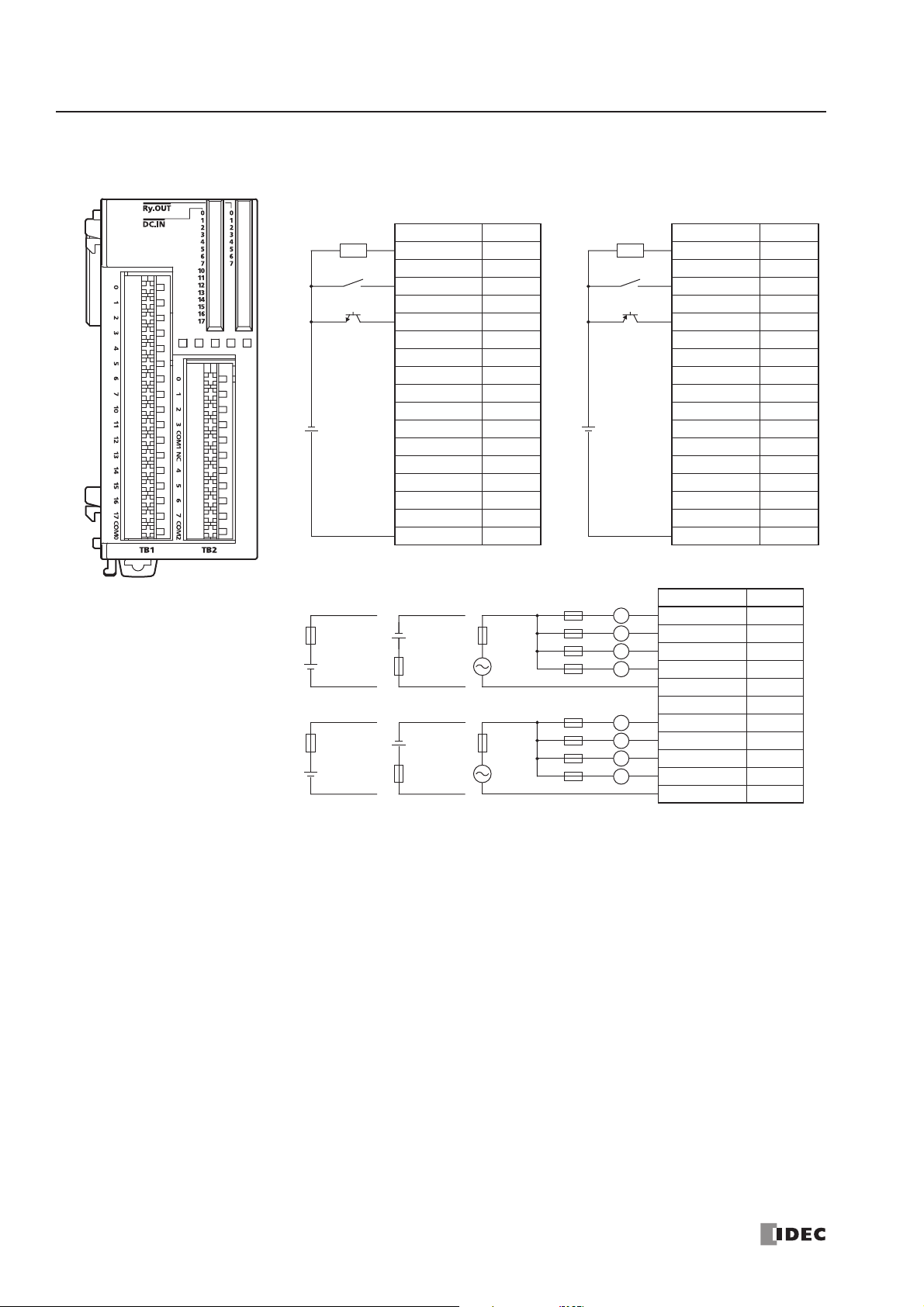
2: MODULE SPECIFICATIONS
2-42 « FC4A MICROSMART USER’S MANUAL »
FC4A-M24BR2 (Mixed I/O Module) — Wire-clamp Terminal Type
Ter minal No. Input
1I0
2I1
3I2
4I3
5I4
6I5
7I6
8I7
9 I10
10 I11
11 I12
12 I13
13 I14
14 I15
15 I16
16 I17
17 COM0
Source Input Wiring
Ter minal No. Input
Sink Input Wiring
2-wire Sensor
–
NPN
–
24V DC
+
Relay Output Wiring
Fuse
+
DC
–
Fuse
+
DC
–
+
–
DC
+
Fuse
–
DC
+
Fuse
Fuse
AC
Fuse
AC
Fuse
2-wire Sensor
–
+
PNP
+
24V DC
–
Load
L
L
L
L
L
L
L
L
Ter minal No. Output
1I0
2I1
3I2
4I3
5I4
6I5
7I6
8I7
9 I10
10 I11
11 I12
12 I13
13 I14
14 I15
15 I16
16 I17
17 COM0
1Q0
2Q1
3Q2
4Q3
5 COM1
6NC
7Q4
8Q5
9Q6
10 Q7
11 COM2
• COM0, COM1, and COM2 terminals are not connected together internally.
• Connect a fuse appropriate for the load.
• For wiring precautions, see pages 3-13 and 3-14.
Page 63
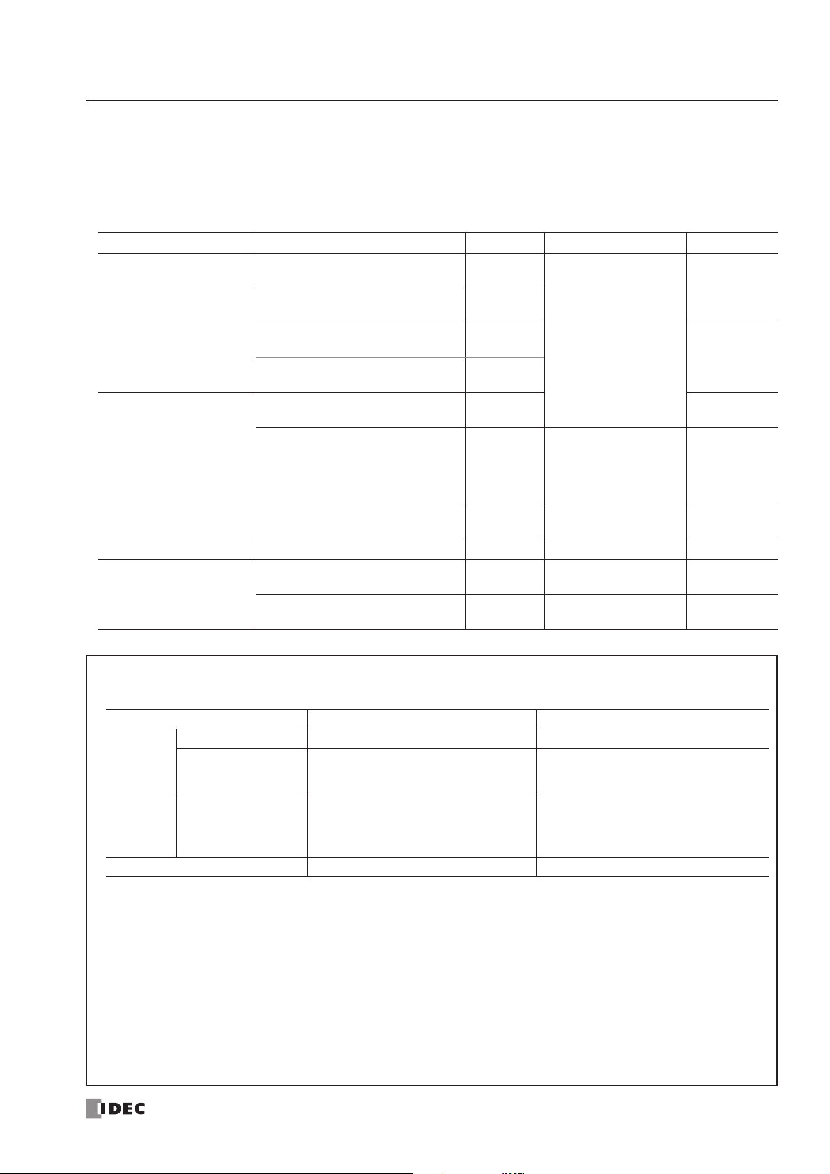
2: MODULE SPECIFICATIONS
« FC4A MICROSMART USER’S MANUAL » 2-43
Analog I/O Modules
Analog I/O modules are available in 3-I/O types, 2-, 4-, and 8-input types, and 1- and 2-output types. The input channel
can accept voltage and current signals, thermocouple and resistance thermometer signals, or thermistor signals. The output
channel generates voltage and current signals.
Analog I/O Module Type Numbers
Name I/O Signal I/O Points Category Type No.
Analog I/O Module
Voltage (0 to 10V DC)
Current (4 to 20mA)
2 inputs
END Refresh Type
FC4A-L03A1
Voltage (0 to 10V DC)
Current (4 to 20mA)
1 output
Thermocouple (K, J, T)
Resistance thermometer (Pt100)
2 inputs
FC4A-L03AP1
Voltage (0 to 10V DC)
Current (4 to 20mA)
1 output
Analog Input Module
Voltage (0 to 10V DC)
Current (4 to 20mA)
2 inputs FC4A-J2A1
Voltage (0 to 10V DC)
Current (4 to 20mA)
Thermocouple (K, J, T)
Resistance thermometer
(Pt100, Pt1000, Ni100, Ni1000)
4 inputs
Ladder Refresh Type
FC4A-J4CN1
Voltage (0 to 10V DC)
Current (4 to 20mA)
8 inputs FC4A-J8C1
Thermistor (NTC, PTC) 8 inputs FC4A-J8AT1
Analog Output Module
Voltage (0 to 10V DC)
Current (4 to 20mA)
1 output END Refresh Type FC4A-K1A1
Voltage (–10 to +10V DC)
Current (4 to 20mA)
2 outputs Ladder Refresh Type FC4A-K2C1
END Refresh Type and Ladder Refresh Type
Depending on the internal circuit design for data refreshing, analog I/O modules are categorized into two types.
Analog I/O Module Category END Refresh Type Ladder Refresh Type
Parameter Refreshing At the end processing in the first scan When executing ANST macro
While CPU
is running
While CPU
is stopped
Data Register Allocation By default Optionally designated in ANST macro
Analog I/O Data
Refreshing
Analog Output Data
Refreshing
At the end processing
When M8025 (maintain outputs while CPU
stopped) is on, output data is refreshed.
When off, output is turned off.
END Refresh Type
Each END refresh type analog I/O module is allocated 20 data registers to store analog I/O data and parameters for controlling analog I/O operation. These data registers are updated at ever y end processing while the CPU module is running.
WindLDR has ANST macro to program the analog I/O modules.
The CPU module checks the analog I/O configuration only once at the end processing in the first scan. If you have
changed the parameter while the CPU is running, stop and restar t the CPU to enable the new parameter.
Ladder Refresh Type
Each ladder refresh type analog I/O module can be allocated any data registers to store analog I/O data and parameters
for controlling analog I/O operation. The data registers are programmed in the ANST macro. Analog I/O data are updated
at the ladder step following the ANST macro. Analog I/O parameters are updated when the ANST macro is executed, so
analog I/O parameters can be changed while the CPU is running.
In the step after ANST macro
(always refreshed whether input to ANST is
on or off)
Maintains output status when the CPU is
stopped. Output data can be changed using
STPA instruction while the CPU is stopped.
See page 24-21.
Page 64
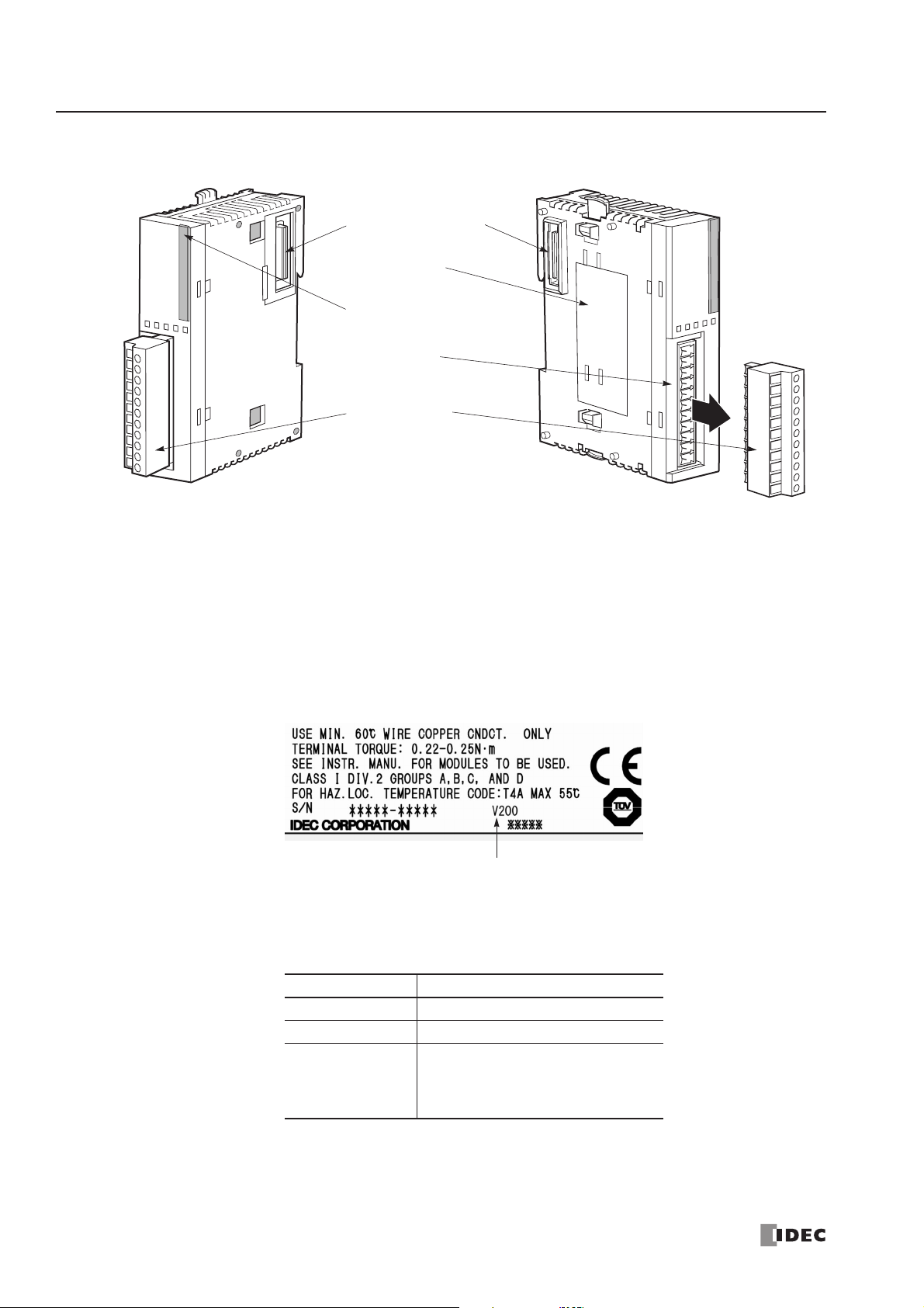
2: MODULE SPECIFICATIONS
2-44 « FC4A MICROSMART USER’S MANUAL »
Parts Description
(1) Expansion Connector Connects to the CPU and other I/O modules.
(The all-in-one 10- and 16-I/O type CPU modules cannot be connected.)
(2) Module Label Indicates the analog I/O module Type No. and specifications.
Four analog I/O modules FC4A-L03A1, FC4A-L03AP1, FC4A-J2A1, and FC4A-K1A1 of
version 200 or higher have the version number indicated on the module label
attached to the side of the module. Confirm the version number because some
specifications differ depending on the version number. Analog I/O modules earlier
than version 200 do not have a version number indicated on the module label.
(3) Power LED (PWR) END refresh type FC4A-L03A1, FC4A-L03AP1, FC4A-J2A1, FC4A-K1A1:
Turns on when power is supplied to the analog I/O module.
(3) Status LED (STAT) Ladder refresh type FC4A-J4CN1, FC4A-J8C1, FC4A-J8AT1, FC4A-K2C1:
Indicates the operating status of the analog I/O module.
(4) Terminal No. Indicates terminal numbers.
(5) Cable Terminal All analog I/O modules have a removable terminal block.
Status LED Analog Input Operating Status
OFF Analog I/O module is stopped
ON Normal operation
Flash
Initializing
Changing configuration
Hardware initialization error
External power supply error
(1) Expansion Connector
(2) Module Label
(3) Power LED (PWR)
(3) Status LED (STAT)
(4) Terminal No.
(5) Cable Terminal
The terminal style depends on the model of analog I/O modules.
Analog I/O Module Version
Page 65

2: MODULE SPECIFICATIONS
« FC4A MICROSMART USER’S MANUAL » 2-45
Analog I/O Module Specifications
General Specifications (END Refresh Type)
Note 1: The external current draw is the value when all analog inputs are used and the analog output value is at 100%.
Note 2: Values in ( ) represent analog I/O modules earlier than version 200. For analog I/O module version, see page 2-44.
General Specifications (Ladder Refresh Type)
Note: The external current draw is the value when all analog inputs are used and the analog output value is at 100%.
Type No. FC4A-L03A1 FC4A-L03AP1 FC4A-J2A1 FC4A-K1A1
Rated Power Voltage 24V DC
Allowable Voltage Range 20.4 to 28.8V DC
Ter minal Arrangement See Analog I/O Module Terminal Arrangement on pages 2-52 to 2-55.
Connector on Mother Board MC1.5/11-G-3.81BK (Phoenix Contact)
Connector Insertion/Removal Durability 100 times minimum
Internal Current Draw
50 mA (5V DC)
0 mA (24V DC)
50 mA (5V DC)
0 mA (24V DC)
50 mA (5V DC)
0 mA (24V DC)
50 mA (5V DC)
0 mA (24V DC)
External Current Draw (Note 1)
50 (45) mA
(Note 2)
(24V DC)
50 (40) mA
(Note 2)
(24V DC)
40 (35) mA
(Note 2)
(24V DC)
40 mA (24V DC)
Weight (Approx.) 100g (85g) (Note 2)
Type No. FC4A-J4CN1 FC4A-J8C1 FC4A-J8AT1 FC4A-K2C1
Rated Power Voltage 24V DC
Allowable Voltage Range 20.4 to 28.8V DC
Ter minal Arrangement See Analog I/O Module Terminal Arrangement on pages 2-52 to 2-55.
Connector on Mother Board MC1.5/10-G-3.81BK (Phoenix Contact)
Connector Insertion/Removal Durability 100 times minimum
Internal Current Draw
50 mA (5V DC)
0 mA (24V DC)
40 mA (5V DC)
0 mA (24V DC)
45 mA (5V DC)
0 mA (24V DC)
60 mA (5V DC)
0 mA (24V DC)
External Current Draw (Note) 55 mA (24V DC) 50 mA (24V DC) 55 mA (24V DC) 85 mA (24V DC)
Weight 140g 140g 125g 110g
Page 66

2: MODULE SPECIFICATIONS
2-46 « FC4A MICROSMART USER’S MANUAL »
Analog Input Specifications (END Refresh Type)
Type No. FC4A-L03A1 / FC4A-J2A1 FC4A-L03AP1
Analog Input Signal Type Voltage Input Current Input Thermocouple
Resistance
Thermometer
Input Range 0 to 10V DC 4 to 20 mA DC
Type K
(0 to 1300°C)
Type J
(0 to 1200°C)
Type T
(0 to 400°C)
Pt 100
3-wire type
(–100 to 500°C)
Input Impedance 1 MΩ minimum 250Ω 1 MΩ minimum 1 MΩ minimum
Allowable Conductor Resistance
(per wire)
——— 200Ω maximum
Input Detection Current ——— 1.0 mA maximum
AD
Conversion
Sample Duration Time 10 (20) ms (Note 1)
10 (20) ms
(Note 1)
20 ms
Sample Repetition Time 20 ms 20 ms
40 (20) ms
(Note 1)
Total Input System
Transfer Time (Note 2)
60 (105) ms + 1 scan time
(Note 1)
60 (200) ms
+ 1 scan time
(Note 1)
80 (200) ms
+ 1 scan time
(Note 1)
Type of Input
Single-ended
input
Differential input
Operating Mode Self-scan
Conversion Method ∑∆ type ADC
Input Error
Maximum Error at 25°C ±0.2% of full scale
±0.2% of full scale
+ cold junction
compensation
error
(±4°C maximum)
±0.2% of full
scale
Temperature Coefficient ±0.006% of full scale/°C
Repeatability after
Stabilization Time
±0.5% of full scale
Non-lineality ±0.2% of full scale
Maximum Error ±1% of full scale
Data
Digital Resolution
4096 increments (12 bits)
13,000 increments maximum (14 bits) (Note 3)
Input Value of LSB 2.5 mV 4 µA
K:
0.100°C/0.180°F
(0.325°C)
J:
0.100°C/0.180°F
(0.300°C)
T:
0.100°C/0.180°F
(0.100°C)
(Note 3)
0.100°C/0.180°F
(0.150°C)
(Note 3)
Data Type in Application
Program
Default: 0 to 4095
Optional: –32768 to 32767 (selectable for each channel) (Note 4)
Monotonicity Yes
Input Data Out of Range Detectable (Note 5)
Page 67

2: MODULE SPECIFICATIONS
« FC4A MICROSMART USER’S MANUAL » 2-47
Note 1: Values in ( ) represent analog I/O modules earlier than version 200. For analog I/O module version, see page 2-44.
Note 2: Total input system transfer time = Sample repetition time + Internal processing time
Note 3: Minimum values represent analog input data in Celsius and Fahrenheit. Values in ( ) represent analog I/O modules
earlier than version 200.
Note 4: The data processed in the analog I/O module can be linear-converted to a value between –32768 and 32767. The
optional range designation, and analog I/O data minimum and maximum values can be selected using data registers allocated to analog I/O modules. See page 24-12.
Note 5: When an error is detected, a corresponding error code is stored to a data register allocated to analog I/O operating
status. See page 24-6.
Noise
Resistance
Maximum Temporary
Deviation during Electrical
Noise Tests
±1% maximum
(when 1 kV is directly applied to the power supply line and a 1 kV clamp
voltage is applied to I/O lines)
(±3% maximum) (Note 1)
(when a 500V clamp voltage is applied to the power
supply and I/O lines)
(Not assured)
(Note 1)
Input Filter No
Recommended Cable for
Noise Immunity
Twisted pair shielded cable —
Crosstalk 2 LSB maximum
Isolation
Between input and power circuit: Isolated
Between input and internal circuit: Photocoupler-isolated
Effect of Improper Input Connection No damage
Maximum Permanent Allowed Overload
(No Damage)
13V DC 40 mA DC —
Selection of Analog Input Signal Type Using programming software
Calibration or Verification to Maintain
Rated Accuracy
Not possible
Type No. FC4A-L03A1 / FC4A-J2A1 FC4A-L03AP1
Analog Input Signal Type Voltage Input Current Input Thermocouple
Resistance
Thermometer
Page 68

2: MODULE SPECIFICATIONS
2-48 « FC4A MICROSMART USER’S MANUAL »
Analog Input Specifications (Ladder Refresh Type)
Type No. FC4A-J4CN1 / FC4A-J8C1 FC4A-J4CN1
Analog Input Signal Type Voltage Input Current Input Thermocouple
Resistance
Thermometer
Input Range 0 to 10V DC 4 to 20 mA DC
Type K:
0 to 1300°C
Type J:
0 to 1200°C
Type T:
0 to 400°C
Pt100, Pt1000:
3-wire type
(–100 to 500°C)
Ni100, Ni1000:
3-wire type
(–60 to 180°C)
Input Impedance 1 MΩ
FC4A-J4CN1:
7Ω
1 MΩ —
FC4A-J8C1:
100Ω
Input Detection Current ———0.1 mA
AD
Conversion
Sample Duration Time 2 ms maximum
Sample Repetition Time
FC4A-J4CN1: 10 ms maximum
FC4A-J8C1: 2 ms maximum
30 ms maximum 10 ms maximum
Total Input System
Transfer Time (Note 1)
FC4A-J4CN1:
50 ms × channels + 1 scan time
FC4A-J8C1:
8 ms × channels + 1 scan time
85 ms
× channels
+ 1 scan time
50 ms
× channels
+ 1 scan time
Type of Input Single-ended input
Operating Mode Self-scan
Conversion Method
FC4A-J4CN1: ∑∆ type ADC
FC4A-J8C1: Successive approximation register method
Input Error
Maximum Error at 25°C ±0.2% of full scale
±0.2% of full scale
+ cold junction
compensation
error (±3°C maximum)
Pt100, Ni100:
±0.4% of full scale
Pt1000, Ni1000:
±0.2% of full scale
Cold Junction
Compensation Error
——
±3.0°C
maximum
—
Temperature Coefficient ±0.005% of full scale/°C
Repeatability after
Stabilization Time
±0.5% of full scale
Non-lineality ±0.04% of full scale
Maximum Error ±1% of full scale
Page 69

2: MODULE SPECIFICATIONS
« FC4A MICROSMART USER’S MANUAL » 2-49
Note 1: Total input system transfer time = Sample repetition time + Internal processing time
The total input system transfer time increases in propor tion to the number of channels used.
Note 2: The data processed in the analog I/O module can be linear-converted to a value between –32768 and 32767. The
optional range designation, and analog I/O data minimum and maximum values can be selected using data registers allocated to analog I/O modules. See page 24-12.
Note 3: When an error is detected, a corresponding error code is stored to a data register allocated to analog I/O operating
status. See page 24-6.
Data
Digital Resolution 50000 increments (16 bits)
K:
Approx.
24000 increments
(15 bits)
J: Approx.
33000 increments
(15 bits)
T: Approx.
10000 increments
(14 bits)
Pt100: Approx.
6400 increments
(13 bits)
Pt1000: Approx.
64000 increments
(16 bits)
Ni100: Approx.
4700 increments
(13 bits)
Ni1000: Approx.
47000 increments
(16 bits)
Input Value of LSB 0.2 mV 0.32 µA
K: 0.058°C
J: 0.038°C
T: 0.042°C
Pt100:
0.086°C
Pt1000: 0.0086°C
Ni100: 0.037°C
Ni1000: 0.0037°C
Data Type in Application
Program
Default: 0 to 50000
Default:
0 to 50000
Pt100, Ni100:
0 to 6000
Pt1000, Ni1000:
0 to 60000
Optional: –32768 to 32767 (selectable for each channel) (Note 2)
—Temperature: Celsius, Fahrenheit
Monotonicity Ye s
Input Data Out of Range Detectable (Note 3)
Noise
Resistance
Maximum Temporary
Deviation during
Electrical Noise Tests
±3% maximum
(when a 500V clamp voltage is applied to the power supply and I/O lines)
Not assured
Input Filter Software
Recommended Cable for
Noise Immunity
Twisted pair cable —
Crosstalk 2 LSB maximum
Isolation
Between input and power circuit: Isolated
Between input and internal circuit: Photocoupler-isolated
Effect of Improper Input Connection No damage
Maximum Permanent Allowed Overload
(No Damage)
11V DC 22 mA DC —
Selection of Analog Input Signal Type Using programming software
Calibration or Verification to Maintain
Rated Accuracy
Not possible
Type No. FC4A-J4CN1 / FC4A-J8C1 FC4A-J4CN1
Analog Input Signal Type Voltage Input Current Input Thermocouple
Resistance
Thermometer
Page 70

2: MODULE SPECIFICATIONS
2-50 « FC4A MICROSMART USER’S MANUAL »
Analog Input Specifications (Ladder Refresh Type)
Note 1: Total input system transfer time = Sample repetition time + Internal processing time
The total input system transfer time increases in propor tion to the number of channels used.
Note 2: The data processed in the analog I/O module can be linear-converted to a value between –32768 and 32767. The
optional range designation, and analog I/O data minimum and maximum values can be selected using data registers allocated to analog I/O modules. See page 24-12.
Note 3: When an error is detected, a corresponding error code is stored to a data register allocated to analog I/O operating
status. See page 24-6.
Type No. FC4A-J8AT1
Analog Input Signal Type NTC Thermistor PTC Thermistor
Input Range –50 to 150°C
Applicable Thermistor 100 kΩ maximum
Input Detection Current 0.1 mA
AD
Conversion
Sample Duration Time 2 ms maximum
Sample Repetition Time 2 ms maximum
Total Input System
Transfer Time (Note 1)
10 ms × channels + 1 scan time (Note 1)
Type of Input Single-ended input
Operating Mode Self-scan
Conversion Method Successive approximation register method
Input Error
Maximum Error at 25°C ±0.2% of full scale
Temperature Coefficient ±0.005% of full scale/°C
Repeatability after
Stabilization Time
±0.5% of full scale
Non-lineality No
Maximum Error ±1% of full scale
Data
Digital Resolution Approx. 4000 increments (12 bits)
Input Value of LSB 0.05°C
Data Type in Application
Program
Default: 0 to 4000
Optional: –32768 to 32767 (selectable for each channel) (Note 2)
Temperature: Celsius, Fahrenheit (NTC only)
Resistance: 0 to 10000
Monotonicity Ye s
Input Data Out of Range Detectable (Note 3)
Noise
Resistance
Maximum Temporary
Deviation during
Electrical Noise Tests
±3% maximum
(when a 500V clamp voltage is applied to the power supply and I/O lines)
Input Filter Software
Recommended Cable for
Noise Immunity
—
Crosstalk 2 LSB maximum
Isolation
Between input and power circuit: Isolated
Between input and internal circuit: Photocoupler-isolated
Effect of Improper Input Connection No damage
Selection of Analog Input Signal Type Using programming software
Calibration or Verification to Maintain
Rated Accuracy
Not possible
Page 71

2: MODULE SPECIFICATIONS
« FC4A MICROSMART USER’S MANUAL » 2-51
Analog Output Specifications
Note 1: Values in ( ) represent analog I/O modules earlier than version 200. For analog I/O module version, see page 2-44.
Note 2: The data processed in the analog I/O module can be linear-converted to a value between –32768 and 32767. The
optional range designation, and analog I/O data minimum and maximum values can be selected using data registers allocated to analog I/O modules. See page 24-12.
Note 3: For analog I/O modules of version 200 or higher, the value represents when 1 kV is directly applied to the power
supply line and a 1 kV clamp voltage is applied to I/O lines. For analog I/O modules earlier than version 200, the value represents when a 500V clamp voltage is applied to the power supply and I/O lines.
Category END Refresh Type Ladder Refresh
Type No. FC4A-L03A1 FC4A-L03AP1 FC4A-K1A1 FC4A-K2C1
Output Range
Voltage 0 to 10V DC –10 to +10V DC
Current 4 to 20 mA DC
Load
Load Impedance 1 (2) kΩ minimum (voltage), 300Ω maximum (current) (Note 1)
Applicable Load Type Resistive load
DA
Conversion
Settling Time
10 (50) ms
(Note 1)
10 (130) ms
(Note 1)
10 (50) ms
(Note 1)
1 ms/ch
Total Output System
Transfer Time
Settling time + 1 scan time
1 ms × channels
+ 1 scan time
Output Error
Maximum Error at
25°C
±0.2% of full scale
Temperature
Coefficient
±0.015% of full scale/°C
±0.005% of full
scale/°C
Repeatability after
Stabilization Time
±0.5% of full scale
Output Voltage Drop ±1% of full scale
Non-lineality ±0.2% of full scale
Output Ripple 1 LSB maximum ±0.1% of full scale
Overshoot 0%
Total Error ±1% of full scale
Data
Digital Resolution 4096 increments (12 bits)
50000 increments
(16 bits)
Output Value
of LSB
Voltage 2.5 mV 0.4 mV
Current 4 µA 0.32 µA
Data Type in
Application Program
Default: 0 to 4095 (voltage, current)
–25000 to 25000
(voltage)
0 to 50000
(current)
Optional: –32768 to 32767 (selectable for each channel) (Note 2)
Monotonicity Ye s
Current Loop Open Not detectable
Noise
Resistance
Maximum Temporary
Deviation during
Electrical Noise Tests
(Note 3)
±1% (±3%) maximum (Note 1) ±3% maximum
Recommended Cable
for Noise Immunity
Twisted pair shielded cable Twisted pair cable
Crosstalk No crosstalk because of 1 channel output 2 LSB maximum
Isolation
Between input and power circuit: Isolated
Between input and internal circuit: Photocoupler-isolated
Effect of Improper Output Connection No damage
Selection of Analog Output Signal Type Using programming software
Calibration or Verification to Maintain
Rated Accuracy
Not possible
Page 72

2: MODULE SPECIFICATIONS
2-52 « FC4A MICROSMART USER’S MANUAL »
Analog I/O Module Terminal Arrangement and Wiring Diagrams
FC4A-L03A1 (Analog I/O Module) — Screw Terminal Type
Applicable Terminal Block: FC4A-PMT11P (supplied with the analog I/O module)
FC4A-L03AP1 (Analog I/O Module) — Screw Terminal Type
Applicable Terminal Block: FC4A-PMT11P (supplied with the analog I/O module)
Ter minal No. Channel
+
24V DC–
+
24V DC
Analog voltage/current
input device
Analog voltage/current
output device
Analog voltage/current
output device
Fuse
+–
+
–
+
–
+
–
–
NC
–
NC
–
OUT
IN0+
IN1+
• Connect a fuse appropriate for the applied voltage and current draw, at the position shown in the
diagram. This is required when equipment containing the MicroSmar t is destined for Europe.
• Do not connect any wiring to unused terminals.
• Before turn on the power, make sure that wiring to the analog I/O module is correct. If wiring is
incorrect, the analog I/O module may be damaged.
Ter minal No. Channel
NC A
–B
NC A
–B
Analog voltage/current
input device
Resistance
thermometer
Thermocouple
24V DC
+–
+
–
Fuse
+
–
A
B’
B
• Connect a fuse appropriate for the applied voltage and current draw, at the position shown in the
diagram. This is required when equipment containing the MicroSmar t is destined for Europe.
• When connecting a resistance thermometer, connect the three wires to RTD (resistance temper-
ature detector) terminals A, B’, and B of input channel IN0 or IN1.
• When connecting a thermocouple, connect the two wires to terminals + and – of input channels
IN0 or IN1.
• Do not connect any wiring to unused terminals.
• Do not connect the thermocouple to a hazardous voltage (60V DC or 42.4V peak or higher).
+
24V DC–
+
–
OUT
IN0+B’
IN1+B’
Page 73

2: MODULE SPECIFICATIONS
« FC4A MICROSMART USER’S MANUAL » 2-53
FC4A-J2A1 (Analog Input Module) — Screw Terminal Type
Applicable Terminal Block: FC4A-PMT11P (supplied with the analog input module)
FC4A-J4CN1 (Analog Input Module) — Screw Terminal Type
Applicable Terminal Block: FC4A-PMT10P (supplied with the analog input module)
Ter minal No. Channel
24V
24V DC0V
NC —
CS
IN0
+
–
I–
CS
IN1
+
–
IN1
I–
CS
IN2
+
–
I–
CS
IN3
+
–
I–
24V DC
+–
Analog voltage/current
output device
Analog voltage/current
output device
Fuse
+
–
+
–
Ter minal No. Channel
NC
NC
NC
NC
• Connect a fuse appropriate for the applied voltage and current draw, at the position shown in the
diagram. This is required when equipment containing the MicroSmar t is destined for Europe.
• Do not connect any wiring to unused terminals.
+
24V DC–
—
IN0+
–
IN1+
–
24V DC
Analog voltage
output device
Analog current
output device
Resistance
thermometer
Thermocouple
+
–
• Connect a fuse appropriate for the applied voltage and current draw, at the position shown in the diagram. This is
required when equipment containing the MicroSmar t is destined for Europe.
• When connecting a resistance thermometer, connect three wires B, B’, and A to the CS (current sense), +, and – termi-
nals of input channels IN0 through IN3, respectively.
• When connecting a thermocouple, connect the + wire to the + terminal and the – wire to the CS and – terminals.
Fuse
+–
+
–
+
–
B
B’
A
NC
NC
NC
• Do not connect the thermocouple to a hazardous voltage (60V DC or 42.4V peak or higher).
• Do not connect any wiring to unused terminals.
• – terminals of input channels IN0 through IN3 are interconnected.
Page 74
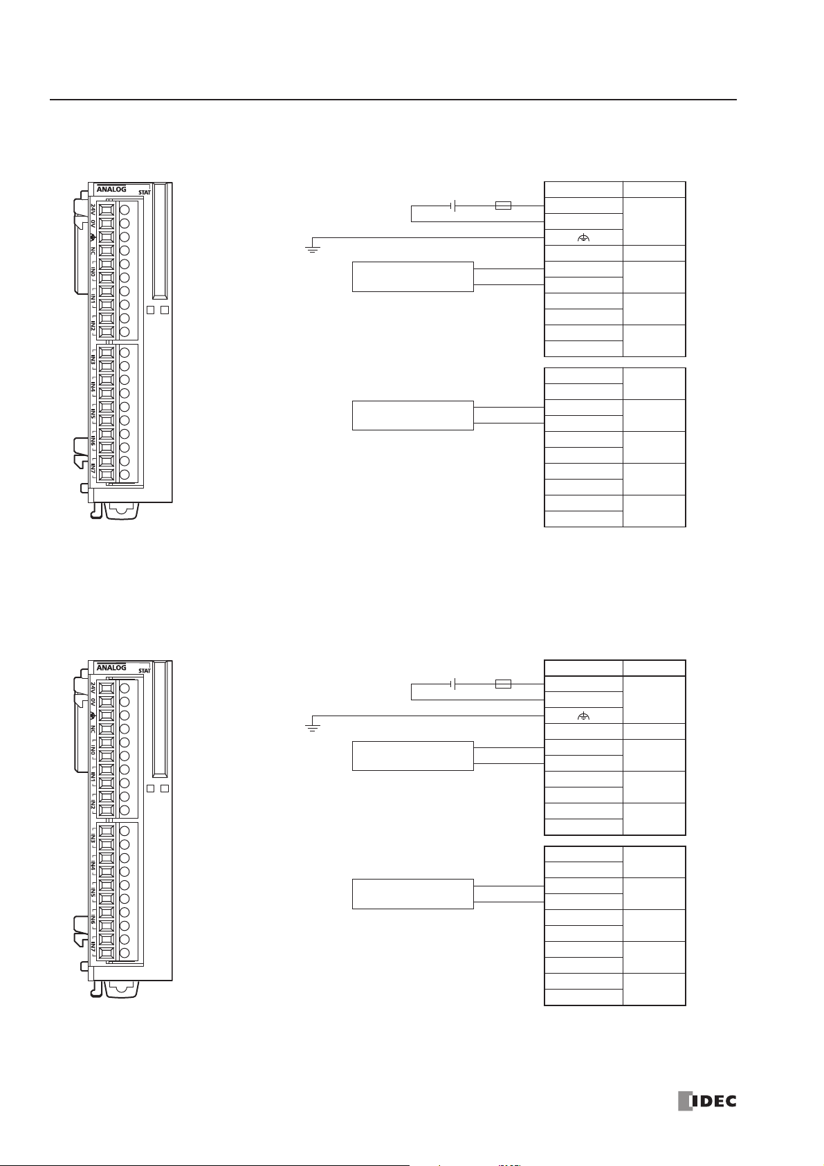
2: MODULE SPECIFICATIONS
2-54 « FC4A MICROSMART USER’S MANUAL »
FC4A-J8C1 (Analog Input Module) — Screw Terminal Type
Applicable Terminal Block: FC4A-PMT10P (supplied with the analog input module)
FC4A-J8AT1 (Analog Input Module) — Screw Terminal Type
Applicable Terminal Block: FC4A-PMT10P (supplied with the analog input module)
Ter minal No. Channel
24V
24V DC0V
NC —
+
IN0
–
+
IN1
–
+
IN2
–
+
IN3
–
+
IN4
–
+
IN5
–
+
IN6
–
+
IN7
–
24V DC
Analog voltage
output device
Analog current
output device
Fuse
+–
+
–
+
–
• Connect a fuse appropriate for the applied voltage and
current draw, at the position shown in the diagram.
This is required when equipment containing the
MicroSmart is destined for Europe.
• Do not connect any wiring to unused terminals.
• – terminals of input channels IN0 through IN7 are
interconnected.
24V DC
+–
NTC
Thermistor
PTC
Thermistor
A
B
A
B
• Connect a fuse appropriate for the applied voltage and
current draw, at the position shown in the diagram.
This is required when equipment containing the
MicroSmart is destined for Europe.
• Do not connect any wiring to unused terminals.
Fuse
Ter minal No. Channel
24V
24V DC0V
NC —
A
B
A
B
A
B
A
B
A
B
A
B
A
B
A
B
IN0
IN1
IN2
IN3
IN4
IN5
IN6
IN7
Page 75
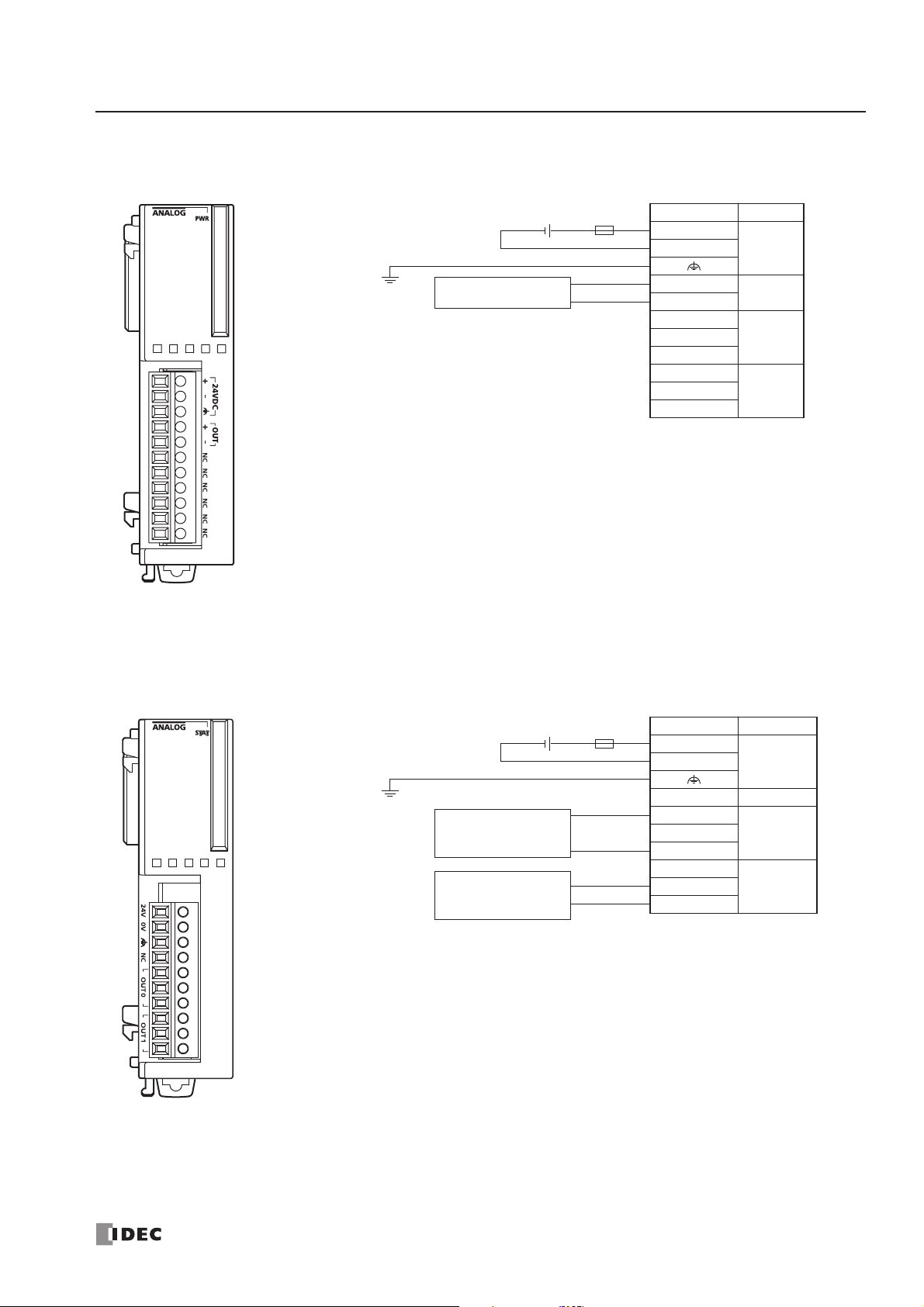
2: MODULE SPECIFICATIONS
« FC4A MICROSMART USER’S MANUAL » 2-55
FC4A-K1A1 (Analog Output Module) — Screw Terminal Type
Applicable Terminal Block: FC4A-PMT11P (supplied with the analog output module)
FC4A-K2C1 (Analog Output Module) — Screw Terminal Type
Applicable Terminal Block: FC4A-PMT10P (supplied with the analog output module)
24V DC
+–
Analog voltage/current
input device
Fuse
+
–
Ter minal No. Channel
+
+
–
NC
NC
NC
NC
• Connect a fuse appropriate for the applied voltage and current draw, at the position shown in the
diagram. This is required when equipment containing the MicroSmar t is destined for Europe.
• Do not connect any wiring to unused terminals.
24V DC–
OUT
—NC
—NC
24V DC
Analog voltage
input device
Analog current
input device
Fuse
+–
+
–
+
–
Ter minal No. Channel
24V
NC —
V+
NC
–
NC
V+
–
24V DC0V
OUT0I+
OUT1I+
• Connect a fuse appropriate for the applied voltage and current draw, at the position shown in the
diagram. This is required when equipment containing the MicroSmar t is destined for Europe.
• Do not connect any wiring to unused terminals.
• – terminals of output channels OUT0 and OUT1 are interconnected.
Page 76

2: MODULE SPECIFICATIONS
2-56 « FC4A MICROSMART USER’S MANUAL »
Type of Protection
Input Circuits
Output Circuits
1 kΩ
NC (A)
Multiplexer
+ (B’)
FC4A-L03A1, FC4A-J2A1 (Ver. 200 or higher)
VCC2
NC
+
100Ω
10Ω
–
1 MΩ
1 MΩ
39 kΩ
FC4A-L03A1, FC4A-L03AP1, FC4A-J2A1
+V2 +V1
15 MΩ
1 kΩ
10Ω
– (B)
1 kΩ
Multiplexer
Input
Selection
Signal
Input Data
Input
Selection
Signal
FC4A-L03AP1 (Ver. 200 or higher)
Current
Source
VCC1 VCC2
15 MΩ
A
B’
B
FC4A-J4CN1
Current
Source
CS
+
7Ω
–
I–
10 kΩ
Multiplexer
Input
Selection
Signal
Input Circuit
–V1
FC4A-J8C1
+
100Ω
10 kΩ
–
Input Circuit
Input
Selection
Signal
FC4A-J8AT1
A
B
Current
Source
FC4A-L03A1, FC4A-L03AP1, FC4A-K1A1 FC4A-K2C1
(Ver. 200 or higher)
+
Output Circuit
–
FC4A-L03A1, FC4A-L03AP1, FC4A-K1A1
Output Circuit
+
–
Output Circuit
Input Circuit
V+
I+
–
Page 77
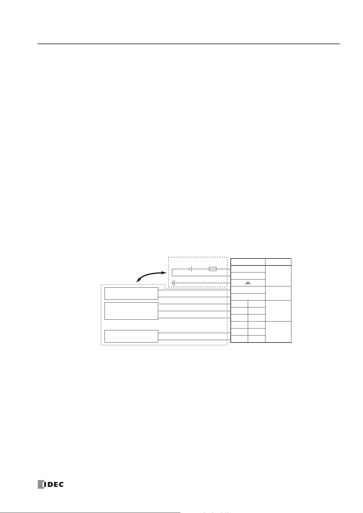
2: MODULE SPECIFICATIONS
« FC4A MICROSMART USER’S MANUAL » 2-57
Power Supply for Analog I/O Modules
When supplying power to the analog I/O modules, take the following considerations.
•
Power Supply for FC4A-L03A1, FC4A-L03AP1, FC4A-J2A1, and FC4A-K1A1
Use separate power supplies for the MicroSmart CPU module and FC4A-L03A1, FC4A-L03AP1, FC4A-J2A1, and FC4A-
K1A1
. Power up the analog I/O modules at least 1 second earlier than the CPU module. This is recommended to ensure
correct operation of the analog I/O control.
Note: When re-powering up the analog I/O modules FC4A-L03A1, -L03AP1, and -J2A1, a time interval is needed before turning on these modules. If a single power supply is used for the MicroSmart CPU module and the analog I/O modules, turn on
the analog I/O modules at least 5 seconds (at 25°C) after turning off these modules. If separate power supplies are used
for the MicroSmart CPU module and the analog I/O modules, turn on the analog I/O modules at least 30 seconds (at 25°C)
after turning off the analog I/O modules whether the CPU module is powered up or not.
• Power Supply for FC4A-J4CN1, FC4A-J8C1, FC4A-J8AT1, and FC4A-K2C1
Use the same power supply for the MicroSmart CPU module and FC4A-J4CN1, FC4A-J8C1, FC4A-J8AT1, and FC4A-K2C1
to suppress the influence of noises.
After the CPU module has started to run, ladder refresh type analog input modules perform initialization for a maximum
of 5 seconds. During this period, the analog input data have an indefinite value. Design the user program to make sure that
the analog input data are read to the CPU module after the analog input operating status has changed to 0 (normal operation). For the analog input operating status, see page 26-13.
Wiring Analog I/O Lines
Separate the analog I/O lines, particularly resistance thermometer inputs, from motor lines as much as possible to suppress
the influence of noises.
Ter minal No. Channel
+
24V DC–
+
Separate the analog I/O line
from the power line.
Analog voltage/current
input device
Resistance
thermometer
Analog voltage/current
output device
24V DC
+
–
A
B’
B
+
–
Fuse
+–
–
NC A
–B
NC A
–B
OUT
IN0+B’
IN1+B’
Page 78
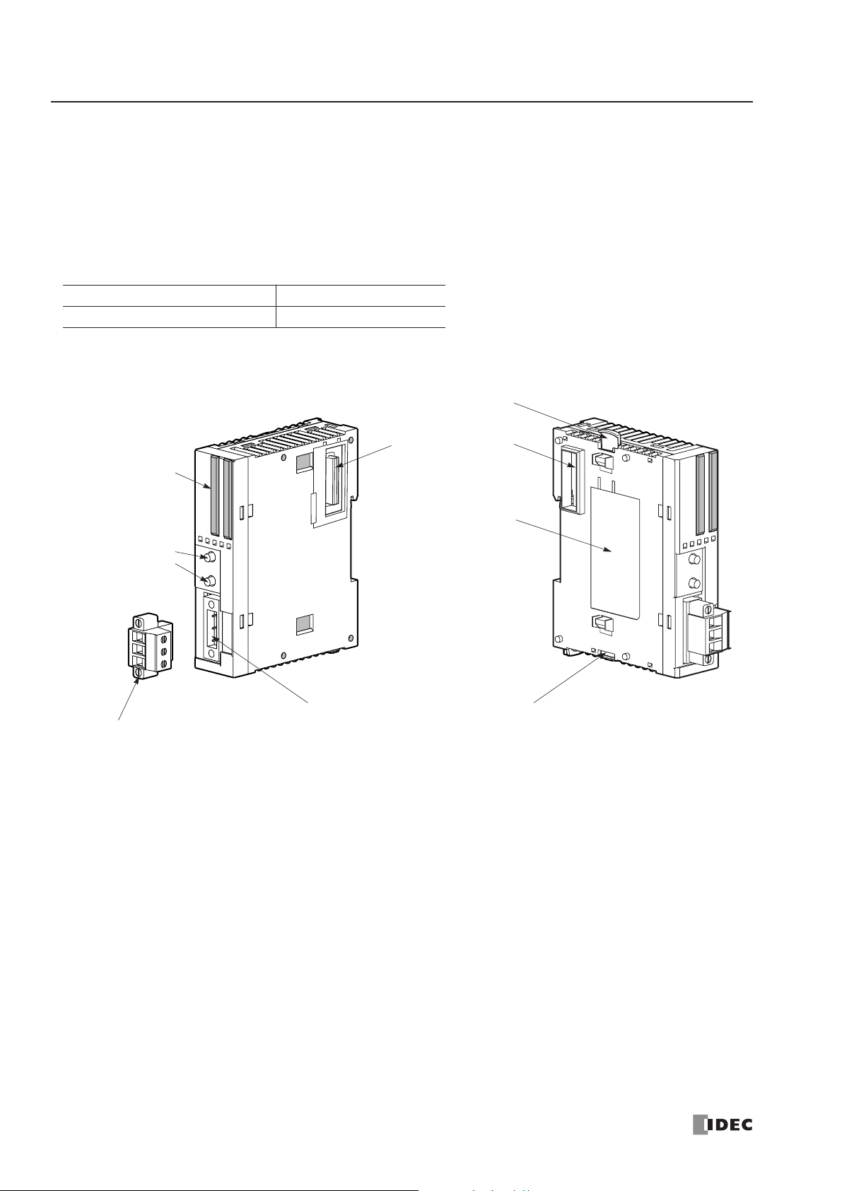
2: MODULE SPECIFICATIONS
2-58 « FC4A MICROSMART USER’S MANUAL »
AS-Interface Master Module
The AS-Interface master module can be used with FC4A-D20RK1, FC4A-D20RS1, FC4A-D40K3, and FC4A-D40S3
CPU modules to communicate digital data with slaves, such as sensor, actuator, and remote I/O data.
One AS-Interface master module can be used with one CPU module. The AS-Interface master module can connect a maximum of 62 digital I/O slaves. A maximum of seven analog I/O slaves can also be connected to the AS-Interface master
module (compliant with AS-Interface ver. 2.1 and analog slave profile 7.3).
AS-Interface Master Module Type Number
Parts Description
(1) LED Indicators Status LEDs: Indicate the AS-Inter face bus status.
I/O LEDs: Indicate the I/O status of the slave specified by the address LEDs.
Address LEDs: Indicate slave addresses.
(2) Pushbuttons Used to select slave addresses, change modes, and store configuration.
(3) AS-Interface Cable Terminal Block
Connects the AS-Interface cable.
One terminal block is supplied with the AS-Interface master module.
When ordering separately, specify Type No. FC4A-PMT3P and quantity
(package quantity: 2).
(4) AS-Interface Cable Connector
Installs the AS-Interface cable terminal block.
(5) Unlatch Button Used to unlatch the AS-Inter face master module from the CPU or I/O module.
(6) Expansion Connector Connects to the CPU and other I/O modules.
(7) Module Label Indicates the AS-Inter face master module Type No. and specifications.
Module Name Type No.
AS-Interface Master Module FC4A-AS62M
(6) Expansion Connector
(7) Module Label
(1) LED Indicators
(4) AS-Interface Cable Connector
(2) Pushbuttons
PB1
PB2
(5) Unlatch Button
(5) Unlatch Button
(3) AS-Interface Cable Terminal Block
(supplied with the AS-Interface master module)
Page 79

2: MODULE SPECIFICATIONS
« FC4A MICROSMART USER’S MANUAL » 2-59
General Specifications (AS-Interface Module)
Communication Specifications (AS-Interface Module)
Operating Temperature 0 to 55°C (operating ambient temperature, no freezing)
Storage Temperature –25 to +70°C (no freezing)
Relative Humidity Level RH1, 30 to 95% (non-condensing)
Pollution Degree 2 (IEC 60664)
Degree of Protection IP20
Corrosion Immunity Free from corrosive gases
Altitude
Operation: 0 to 2,000m (0 to 6,565 feet)
Transport: 0 to 3,000m (0 to 9,840 feet)
Vibration Resistance
When mounted on a DIN rail:
10 to 57 Hz amplitude 0.075 mm, 57 to 150 Hz acceleration 9.8 m/s
2
2 hours per axis on each of three mutually perpendicular axes
When mounted on a panel surface:
2 to 25 Hz amplitude 1.6 mm, 25 to 100 Hz acceleration 39.2 m/s
2
90 minutes per axis on each of three mutually perpendicular axes
Shock Resistance
147 m/s
2
, 11 ms duration, 3 shocks per axis, on three mutually perpendic-
ular axes (IEC 61131)
External Power Supply AS-Inter face power supply, 29.5 to 31.6V DC
AS-Interface Current Draw
65 mA (normal operation)
110 mA maximum
Effect of Improper Input Connection No damage
Connector on Mother Board MSTB2.5/3-GF-5.08BK (Phoenix Contact)
Connector Insertion/Removal Durability 100 times minimum
Internal Current Draw
80 mA (5V DC)
0 mA (24V DC)
AS-Interface Master Module
Power Consumption
540 mW
Weight 85g
Maximum Bus Cycle
When 1 through 19 slaves are connected: 3 ms
When 20 through 62 slaves are connected: 0.156 × (1 + N) ms
where N is the number of active slaves
5 ms maximum when 31 standard or A/B slaves are connected
10 ms maximum when 62 A/B slaves are connected
Maximum Slaves
Standard slaves: 31
A/B slaves: 62
When using a mix of standard slaves and A/B slaves together, the standard slaves can
only use addresses 1(A) through 31(A). Also, when a standard slave takes a cer tain
address, the B address of the same number cannot be used for A/B slaves.
Maximum I/O Points
Standard slaves: 248 total (124 inputs + 124 outputs)
A/B slaves: 434 total (248 inputs + 186 outputs)
Maximum Cable Length
AS-Interface cable
2-wire flat cable
When using no repeater or extender: 100m
When using a total of 2 repeaters or extenders: 300m
Single wires 200 mm
Rated Bus Voltage 30V DC
Page 80

2: MODULE SPECIFICATIONS
2-60 « FC4A MICROSMART USER’S MANUAL »
HMI Module
The optional HMI module can mount on any all-in-one type CPU module, and also on the HMI base module mounted next
to any slim type CPU module. The HMI module makes it possible to manipulate the RAM data in the CPU module without using the Online menu options in WindLDR. For details about operating the HMI module, see page 5-32. For installing
and removing the HMI module, see pages 3-3 and 3-4.
HMI Module Type Number
Parts Description
(1) Display Screen The liquid crystal display shows menus, operands, and data.
(2) ESC Button Cancels the current operation, and returns to the immediately preceding operation.
(3) ▲ Button Scrolls up the menu, or increments the selected operand number or value.
(4) ▼ Button Scrolls down the menu, or decrements the selected operand number or value.
(5) OK Button Goes into each control screen, or enters the current operation.
(6) HMI Connector Connects to the all-in-one CPU module or HMI base module.
HMI Module Specifications
Module Name Type No.
HMI Module FC4A-PH1
Type No. FC4A-PH1
Power Voltage 5V DC (supplied from the CPU module)
Internal Current Draw 200 mA DC
Weight 20g
(1) Display Screen
(2) ESC Button
(6) HMI Connector(3) ▲ Button (4)
▼ Button (5) OK Button
Caution
• Turn off the power to the MicroSmart before installing or removing the HMI module to prevent
electrical shocks and damage to the HMI module.
• Do not touch the connector pins with hand, otherwise contact characteristics of the connector
may be impaired.
Page 81
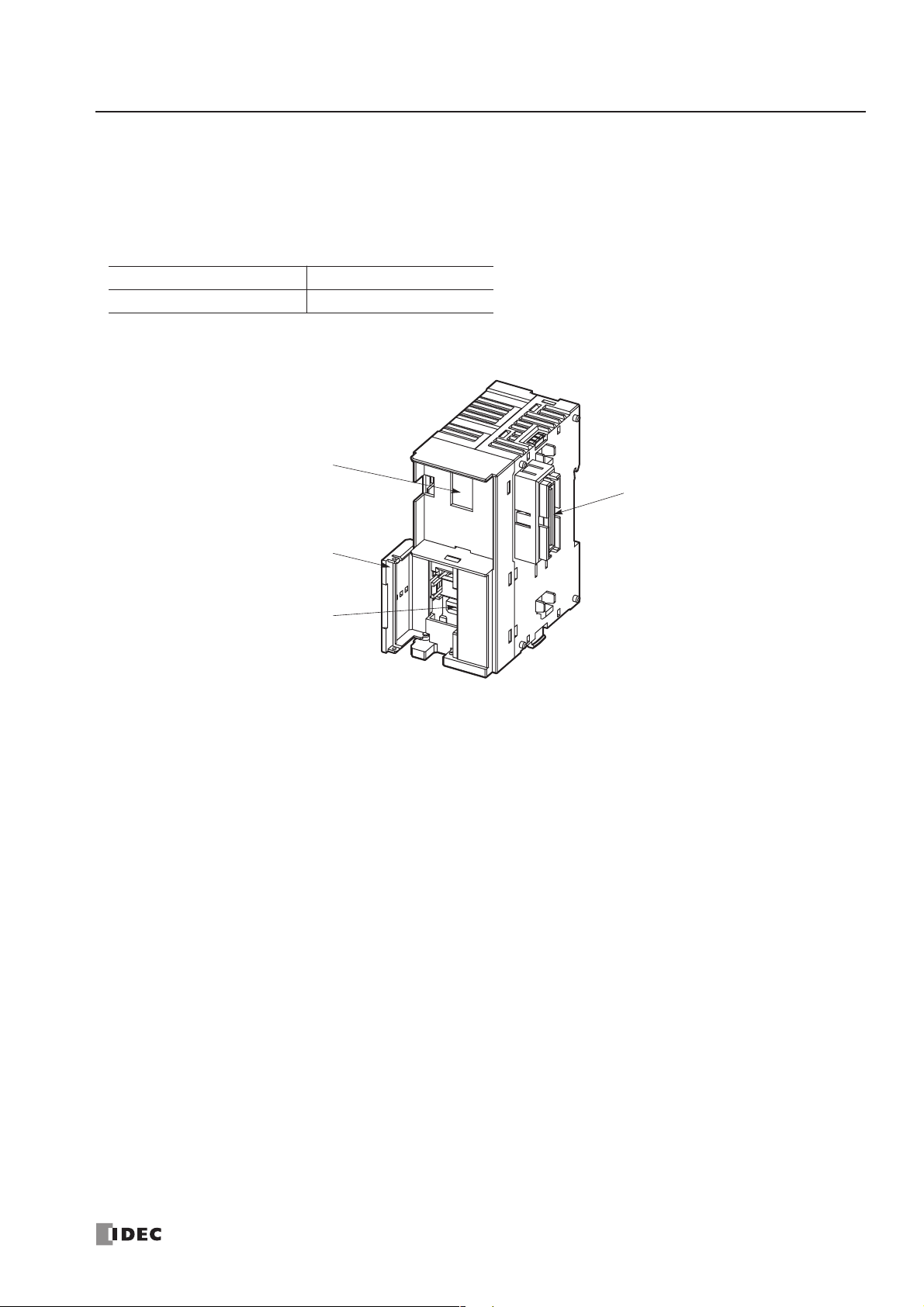
2: MODULE SPECIFICATIONS
« FC4A MICROSMART USER’S MANUAL » 2-61
HMI Base Module
The HMI base module is used to install the HMI module when using the slim type CPU module. The HMI base module
also has a port 2 connector to attach an optional RS232C or RS485 communication adapter.
When using the all-in-one type CPU module, the HMI base module is not needed to install the HMI module.
HMI Base Module Type Number
Parts Description
(1) HMI Connector For installing the HMI module.
(2) Hinged Lid Open the lid to gain access to the port 2 connector.
(3) Port 2 Connector For installing an optional RS232C or RS485 communication adapter.
(4) Communication Connector Connects to the slim type CPU module.
Module Name Type No.
HMI Base Module FC4A-HPH1
(1) HMI Connector
(2) Hinged Lid
(4) Communication Connector
(3) Port 2 Connector
Page 82

2: MODULE SPECIFICATIONS
2-62 « FC4A MICROSMART USER’S MANUAL »
Communication Adapters and Communication Modules
All MicroSmart CPU modules have communication port 1 for RS232C communication. In addition, all-in-one 16- and 24I/O type CPU modules have a port 2 connector. An optional communication adapter can be installed on the port 2 connector for RS232C or RS485 communication. The 10-I/O type CPU module does not have a port 2 connector.
A communication module can be attached to any slim type CPU module to use port 2 for additional RS232C or RS485
communication. When the HMI base module is attached to a slim type CPU module, a communication adapter can be
installed to the port 2 connector on the HMI base module.
When using the RS232C communication adapter or communication module for port 2, maintenance communication, user
communication, and modem communication are made possible. With the RS485 communication adapter or communication module installed, maintenance communication, data link communication, and user communication (upgraded CPU
modules of slim 20-I/O relay output types and 40-I/O types only) can be used on port 2.
Communication Adapter and Communication Module Type Numbers
Parts Description
(1) Port 2 RS232C or RS485 communication port 2.
(2) Connector Connects to the port 2 connector on the all-in-one type CPU module or HMI base module.
(1) Communication Connector Connects to the slim type CPU module.
(2) Port 2 RS232C or RS485 communication port 2.
(3) Hinged Lid Open the lid to gain access to port 2.
Name Termination Type No.
RS232C Communication Adapter Mini DIN connector FC4A-PC1
RS485 Communication Adapter
Mini DIN connector FC4A-PC2
Screw Terminal Block FC4A-PC3
RS232C Communication Module Mini DIN connector FC4A-HPC1
RS485 Communication Module
Mini DIN connector FC4A-HPC2
Screw Terminal Block FC4A-HPC3
(1) Port 2
(2) Connector
RS232C Communication Adapter (Mini DIN)
RS485 Communication Adapter (Mini DIN)
RS485 Communication Adapter (Screw Terminal)
(1) Port 2
(2) Connector
RS232C Communication Module (Mini DIN)
RS485 Communication Module (Mini DIN)
(1) Communication
(3) Hinged Lid
Connector
(3) Hinged Lid
RS485 Communication Module (Screw Terminal)
(1) Communication
Connector
(2) Port 2
(2) Port 2
Page 83

2: MODULE SPECIFICATIONS
« FC4A MICROSMART USER’S MANUAL » 2-63
Communication Adapter and Communication Module Specifications
Note 1: RS485 user communication is available on upgraded CPU modules only, see page 17-1.
Note 2: Recommended cable for RS485: Twisted-pair shielded cable with a minimum core wire of 0.3 mm
2
.
Conductor resistance 85 Ω/km maximum, shield resistance 20 Ω/km maximum.
The proper tightening torque of the terminal screws on the RS485 communication adapter and RS485 communication module is 0.22 to 0.25 N·m. For tightening the screws, use screwdriver SZS 0,4 x 2,5 (Phoenix Contact).
Installing the Communication Adapter and Communication Module
Communication Adapter
To install the communication adapter on the all-in-one type CPU module, open the hinged lid and remove the dummy cartridge. Push the communication adapter into the port 2 connector from the front until it bottoms and is secured by the
latches. Similarly, when installing the communication adapter on the HMI base module, open the hinged lid, and push the
communication adapter into the port 2 connector from the front until it bottoms and is secured by the latches.
Type No.
FC4A-PC1
FC4A-HPC1
FC4A-PC2
FC4A-HPC2
FC4A-PC3
FC4A-HPC3
Standards EIA RS232C EIA RS485 EIA RS485
Maximum Baud Rate 19,200 bps 19,200 bps
Computer link: 19,200 bps
User com.: 19,200 bps
Data link: 38,400 bps
Maintenance Communication
(Computer Link)
Possible Possible Possible
User Communication Possible Not possible Possible (Note 1)
Modem Communication Possible Not possible Not possible
Data Link Communication Not possible Not possible Possible
Quantity of Slave Stations ——31
Maximum Cable Length Special cable Special cable 200m (Note 2)
Isolation between Internal Circuit
and Communication Port
Not isolated Not isolated Not isolated
Caution
• Before installing the communication adapter or communication module, turn off the power to the
MicroSmart
CPU module. Otherwise, the communication adapter or CPU module may be dam-
aged, or the MicroSmart may not operate correctly.
Communication Adapter
Communication Adapter
Hinged Lid
Port 2 Connector
Dummy Cartridge
After installing the communication adapter,
attach the dummy cartridge again.
Hinged Lid
Port 2 Connector
Page 84

2: MODULE SPECIFICATIONS
2-64 « FC4A MICROSMART USER’S MANUAL »
After installing the communication adapter on an all-in-one
type CPU module, view the communication adapter through
the dummy cartridge opening, and check to see that the PC
board of the communication adapter is in a lower level than the
top of the terminal block.
Communication Module
When installing a communication module on the slim type
CPU module, remove the communication connector cover
from the slim type CPU module. See page 3-6.
Place the communication module and CPU module side by
side. Put the communication connectors together for easy
alignment.
With the communication connectors aligned correctly and the
blue unlatch button in the down position, press the communication module and CPU module together until the latches click to
attach the modules together firmly. If the unlatch button is in
the up position, push down the button to engage the latches.
Removing the Communication Adapter and Communication Module
Communication Adapter
To remove the communication adapter from the all-in-one type
CPU module, first remove the dummy cartridge. While pushing
up the communication adapter PC board with a finger through
the dummy cartridge opening, disengage the latches from the
communication adapter using a flat screwdriver. Pull out the
communication adapter from the port 2 connector. When
removing the communication adapter from the HMI module,
take similar steps.
Communication Module
If the modules are mounted on a DIN rail, first remove the
modules from the DIN rail as described on page 3-7.
Push up the blue unlatch button to disengage the latches, and
pull the modules apart as shown on the right.
Unlatch Button Communication Connector Cover
Communication Module Slim Type CPU Module
Caution
• Before removing the communication adapter or communication module, turn off the power to the
MicroSmart CPU module. Otherwise, the communication adapter or CPU module may be dam-
aged, or the MicroSmart may not operate correctly.
Communication
Adapter PC Board
Ter minal Block
Unlatch Button
Page 85

2: MODULE SPECIFICATIONS
« FC4A MICROSMART USER’S MANUAL » 2-65
Memory Cartridge
A user program can be stored on an optional memory cartridge installed on a MicroSmart CPU module from a computer
running WindLDR, and the memory cartridge can be installed on another MicroSmart CPU module of the same type. Using
a memory cartridge, the CPU module can exchange user programs without using a computer.
This feature is available on all models of CPU modules.
Memory Cartridge Type Number
User Program Execution Priority
Depending whether a memory cartridge is installed on the MicroSmart CPU module or not, a user program stored on the
memory cartridge or on the CPU module EEPROM is executed, respectively.
Memory Cartridge Specifications
Note: The optional clock cartridge (FC4A-PT1) and the memory car tridge cannot be used together on the all-in-one type CPU
module. The clock cartridge and the memory cartridge can be used together on the slim type CPU module.
User Program Compatibility
The CPU module can execute only user programs created for the same CPU module type. When installing a memory cartridge, make sure that the user program stored on the memory cartridge matches the CPU module type. If the user program
is not for the same CPU module type, a user program syntax error occurs and the CPU module cannot run the user program.
Module Name Type No. Remarks
32KB Memory Cartridge FC4A-PM32
64KB Memory Cartridge FC4A-PM64
The 64KB memory cartridge can be used on slim type CPU modules
FC4A-D20RK1, FC4A-D20RS1, FC4A-D40K3, and FC4A-D40S3 with system program ver. 201 or higher only. The program capacity expands up
to 64,500 bytes (10,750 steps).
To edit user programs over 32 KB (5200 steps), use WindLDR ver. 4.2
or higher.
Memory Cartridge User Program Execution Priority
Installed on the CPU Module
The user program stored on the memor y cartridge is executed.
When the memory cartridge does not store a user program, the user program
on the CPU module EEPROM is executed.
When a memory cartridge is installed on the CPU module, the user program
can be downloaded from the memory cartridge to the CPU module by designating in WindLDR Function Area Settings. To perform user program download
from the memory cartridge, use CPU system program ver. 210 or higher and
WindLDR ver 5.31 or higher.
Not installed on the CPU Module The user program stored on the EEPROM in the CPU module is executed.
Type No. FC4A-PM32 FC4A-PM64
Memory Type EEPROM
Accessible Memory Capacity 32 KB 64 KB
Hardware for Storing Data CPU module
Software for Storing Data WindLDR WindLDR ver. 4.20 or higher
Quantity of Stored Programs One user program can be stored on one memor y car tridge.
• Compatibility of User Program with CPU Modules
When a memory cartridge contains a user program for higher functionality, do not install the memory cartridge into CPU modules with lower functionality, otherwise the user program is not executed correctly. Make sure that the user program in the memory cartridge is compatible with the
CPU module.
Caution
Page 86

2: MODULE SPECIFICATIONS
2-66 « FC4A MICROSMART USER’S MANUAL »
Downloading and Uploading User Program to and from Memory Car tridge
When a memory cartridge is installed on the CPU module, a user program is downloaded to and uploaded from the memory cartridge using WindLDR on a computer. When a memory cartridge is not installed on the CPU module, a user program
is downloaded to and uploaded from the CPU module. For the procedures to download a user program from WindLDR on a
computer, see page 4-8.
With a memory cartridge installed on a CPU module, if the user program stored on the memory cartridge does not match
the CPU module type, downloading is possible, but uploading is not possible. To upload a user program, make sure that
the existing user program stored on the memory cartridge matches the CPU module type. Downloading is always possible
to new blank memory cartridges installed on any type of CPU modules.
Downloading User Program from Memory Car tridge to the CPU Module
To designate user program download from the memory cartridge, use a CPU module with system program ver. 210 or
higher and WindLDR ver 5.31 or higher. Install a memory cartridge on the CPU module connected to a computer, and
power up the CPU module.
Programming WindLDR
1. From the WindLDR menu bar, select Configure >
Function Area Settings. The Function Area Set-
tings dialog box appears.
2. Select the Others tab.
3. Under Memory Cartridge Setting, click the check box to the left of Download the user program from a memory
cartridge when installed on a CPU module.
Checked: The user program is downloaded from the memory car tridge to the CPU module.
Unchecked: The user program is not downloaded from the memor y car tridge to the CPU module.
4. Click the OK button.
5. Download the user program to the memory cartridge to complete the designation in the memory cartridge.
6. Shut down the CPU module and remove the memory cartridge. Install the memory cartridge on another CPU module.
Power up the CPU module, then the user program is downloaded from the memory cartridge to the CPU module.
If the user program in the CPU module is write-protected or read/write-protected, the user program can be downloaded
only when the password in the memory cartridge matches the password in the CPU module. For user program protection
password, see page 5-25.
Page 87

2: MODULE SPECIFICATIONS
« FC4A MICROSMART USER’S MANUAL » 2-67
Installing and Removing the Memory Cartridge
All-in-One Type CPU Module
The cartridge connector is normally closed with a
dummy cartridge. To install the memory cartridge,
open the terminal cover and remove the dummy cartridge from the CPU module. Make sure of correct
orientation of the memory cartridge. Insert the memory cartridge into the cartridge connector until it bottoms. Do not insert the memory cartridge diagonally,
otherwise the terminal pins will be deformed.
After installing the memory cartridge, close the terminal cover.
To remove the memory cartridge, hold both edges of
the memory cartridge and pull it out.
Slim Type CPU Module
Cartridge connectors 1 and 2 are normally closed
with a dummy cartridge. To install the memory cartridge, open the hinged lid and remove the dummy
cartridge from the CPU module. Make sure of correct
orientation of the memory cartridge, and insert the
memory cartridge into cartridge connector 1 or 2
until it bottoms. After installing the memory cartridge, close the hinged lid.
Only one memory cartridge can be installed to either
cartridge connector 1 or 2 on the slim type CPU
module. A memory cartridge and a clock cartridge
can be installed at the same time.
To remove the memory cartridge, hold both edges of
the memory cartridge and pull it out.
Hinged Lid
Cartridge Connector 1
Memory Cartridge
FC4A-PM32
Cartridge Connector 2
Caution
• Before installing or removing the memory cartridge, turn off the power to the MicroSmart CPU
module. Otherwise, the memory cartridge or CPU module may be damaged, or the MicroSmart
may not operate correctly.
• Do not touch the connector pins with hand, otherwise electrostatic discharge may damage the
internal elements.
Ter minal Cover
Memory Cartridge
FC4A-PM32
Cartridge
Connector
Page 88

2: MODULE SPECIFICATIONS
2-68 « FC4A MICROSMART USER’S MANUAL »
Clock Cartridge
With the optional clock cartridge installed on any type of MicroSmart CPU modules, the MicroSmar t can be used for
time-scheduled control such as illumination and air conditioners. For setting the calendar/clock, see page 15-5.
Clock Cartridge Type Number
Clock Cartridge Specifications
The optional memory cartridge (FC4A-PM32) and the clock cartridge cannot be used together on the all-in-one type CPU
module. The memory cartridge and the clock cartridge can be used together on the slim type CPU module.
Installing and Removing the Clock Cartridge
All-in-One Type CPU Module
The cartridge connector is normally closed with a
dummy cartridge. To install the clock cartridge, open
the terminal cover and remove the dummy cartridge
from the CPU module. Make sure of correct orientation of the clock cartridge. Insert the clock cartridge
into the cartridge connector until it bottoms. Do not
insert the clock cartridge diagonally, otherwise the
terminal pins will be deformed. After installing the
clock cartridge, close the terminal cover.
To remove the clock cartridge, hold both edges of the
clock cartridge and pull it out.
Slim Type CPU Module
To install the clock cartridge, open the hinged lid and
remove the dummy cartridge from the CPU module.
Make sure of correct orientation of the clock cartridge, and insert the clock cartridge into cartridge
connector 1 or 2 until it bottoms. After installing the
clock cartridge, close the hinged lid.
Only one clock cartridge can be installed to either
cartridge connector 1 or 2 on the slim type CPU
module. A clock cartridge and a memory cartridge
can be installed at the same time.
To remove the clock cartridge, hold both edges of the
clock cartridge and pull it out.
Module Name Type No.
Clock Cartridge FC4A-PT1
Accuracy ±30 sec/month (typical) at 25°C
Backup Duration Approx. 30 days (typical) at 25°C after backup battery fully charged
Battery Lithium secondary batter y
Charging Time Approx. 10 hours for charging from 0% to 90% of full charge
Battery Life Approx. 100 recharge cycles after discharging down to 10% of full charge
Replaceability Not possible to replace battery
Caution
• Before installing or removing the clock cartridge, turn off the power to the MicroSmart
module. Otherwise, the clock cartridge or CPU module may be damaged, or the MicroSmart may
not operate correctly.
• Do not touch the connector pins with hand, otherwise electrostatic discharge may damage the
internal elements.
Ter minal Cover
Clock Cartridge
FC4A-PT1
Cartridge
Connector
Hinged Lid
Cartridge Connector 1
Clock Cartridge
FC4A-PT1
Cartridge Connector 2
CPU
Page 89
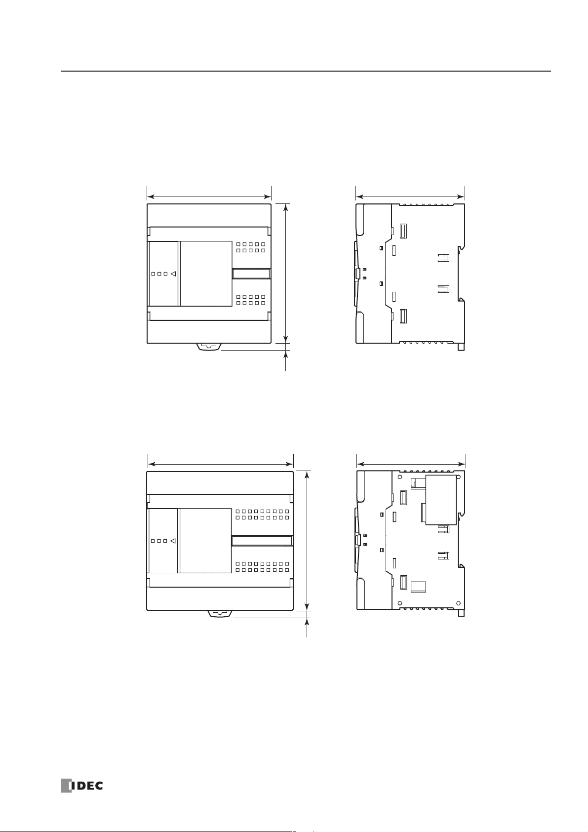
2: MODULE SPECIFICATIONS
« FC4A MICROSMART USER’S MANUAL » 2-69
Dimensions
All MicroSmart modules have the same profile for consistent mounting on a DIN rail.
CPU Modules
FC4A-C10R2, FC4A-C10R2C, FC4A-C16R2, FC4A-C16R2C
FC4A-C24R2, FC4A-C24R2C
80.0
90.04.5*
*8.5 mm when the clamp is pulled out.
95.0 70.0
70.0
90.04.5*
*8.5 mm when the clamp is pulled out.
All dimensions in mm.
Page 90
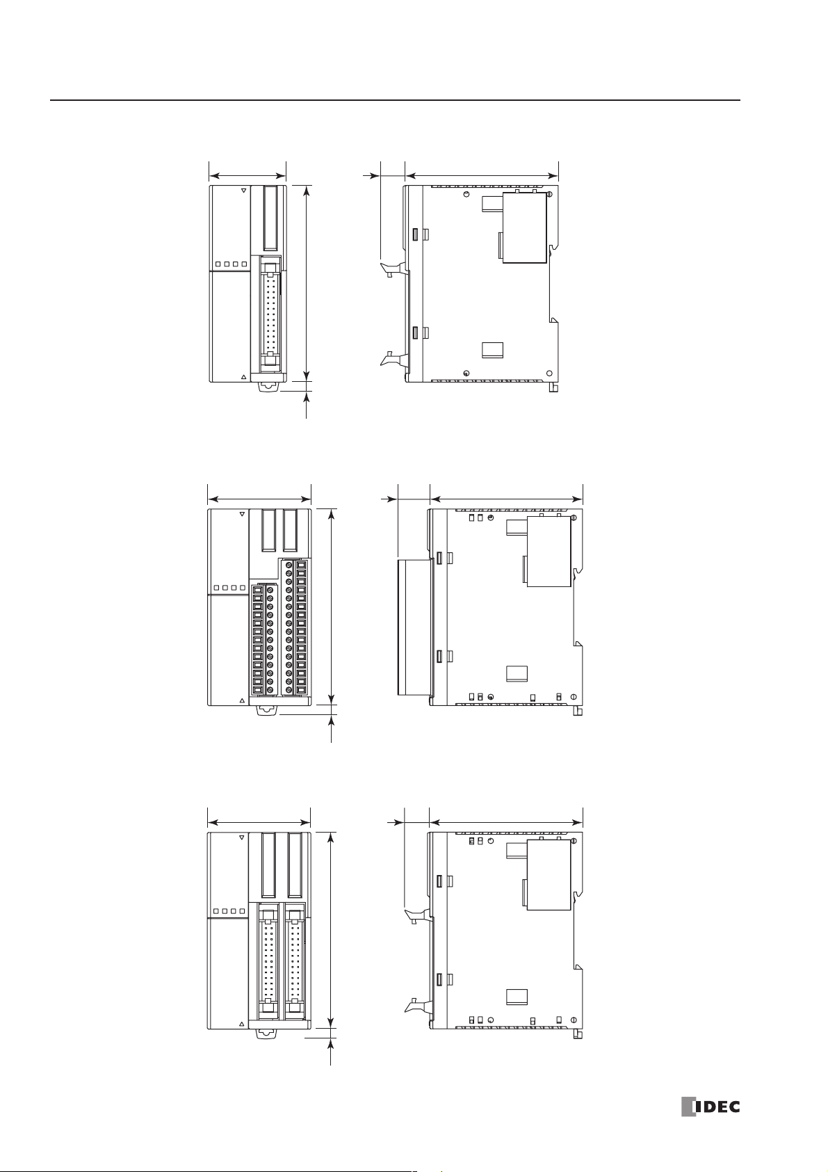
2: MODULE SPECIFICATIONS
2-70 « FC4A MICROSMART USER’S MANUAL »
FC4A-D20K3, FC4A-D20S3
FC4A-D20RK1, FC4A-D20RS1
FC4A-D40K3, FC4A-D40S3
47.5 14.6 70.0
90.04.5*
*8.5 mm when the clamp is pulled out.
35.4 11.3 70.0
90.04.5*
*8.5 mm when the clamp is pulled out.
47.5 11.3 70.0
90.04.5*
*8.5 mm when the clamp is pulled out.
All dimensions in mm.
Page 91
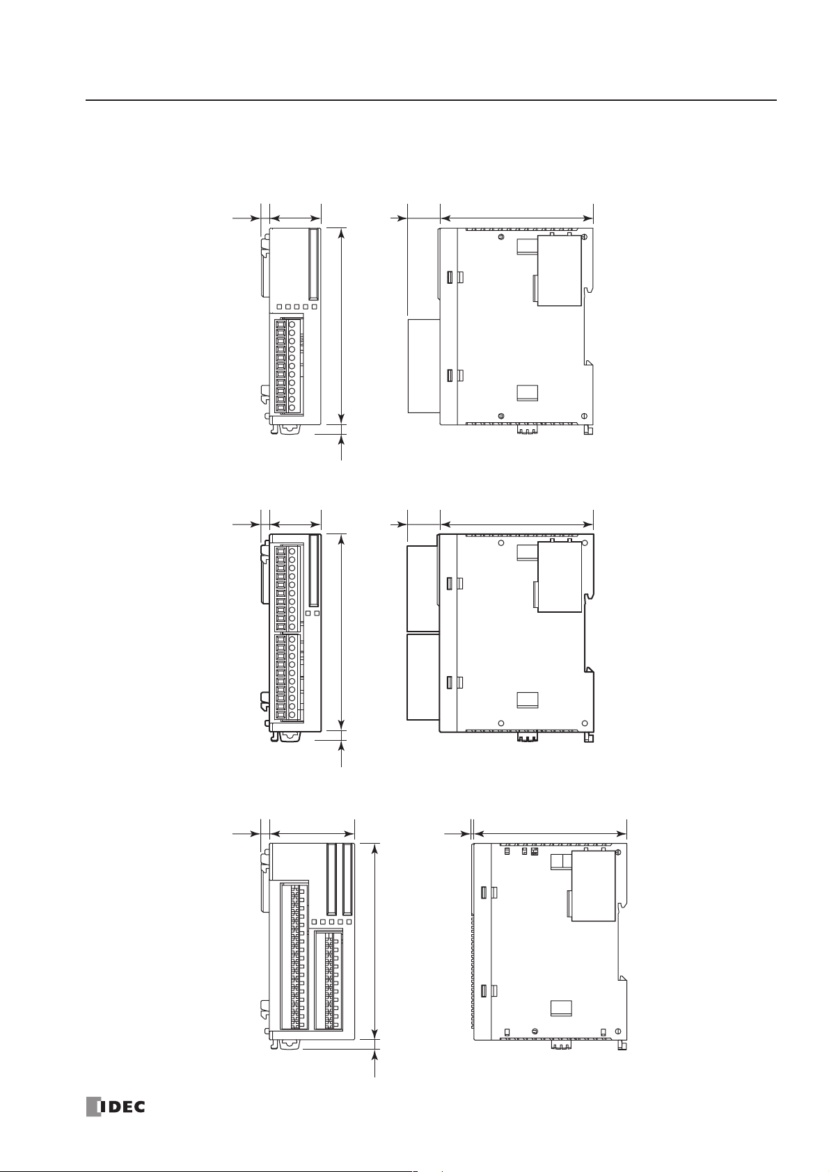
2: MODULE SPECIFICATIONS
« FC4A MICROSMART USER’S MANUAL » 2-71
I/O Modules
FC4A-N08B1, FC4A-N08A11, FC4A-R081, FC4A-T08K1, FC4A-T08S1, FC4A-M08BR1,
FC4A-L03A1, FC4A-L03AP1, FC4A-J2A1, FC4A-K1A1
FC4A-N16B1, FC4A-R161
FC4A-M24BR2
23.5 14.6 70.0
90.04.5*
3.8
*8.5 mm when the clamp is pulled out.
3.8
23.5 14.6 70.0
90.04.5*
*8.5 mm when the clamp is pulled out.
3.8
39.1
90.04.5*
*8.5 mm when the clamp is pulled out.
1.0
70.0
All dimensions in mm.
Page 92

2: MODULE SPECIFICATIONS
2-72 « FC4A MICROSMART USER’S MANUAL »
FC4A-N16B3, FC4A-T16K3, FC4A-T16S3
FC4A-N32B3, FC4A-T32K3, FC4A-T32S3
29.7 11.3 70.0
90.04.5*
3.8
*8.5 mm when the clamp is pulled out.
3.8
17.6 11.3 70.0
90.04.5*
*8.5 mm when the clamp is pulled out.
Page 93
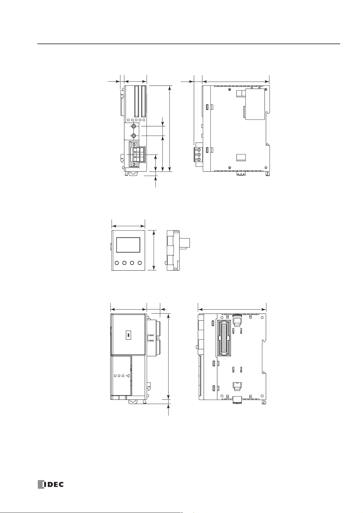
2: MODULE SPECIFICATIONS
« FC4A MICROSMART USER’S MANUAL » 2-73
AS-Interface Module FC4A-AS62M
HMI Module FC4A-PH1
HMI Base Module FC4A-HPH1
35.0
42.0
3.8
23.5
9.4 70.0
90.0
10
37.5
17.7
*8.5 mm when the clamp is pulled out.
4.5*
38.0 13.9
71.0
90.04.5*
*8.5 mm when the clamp is pulled out.
All dimensions in mm.
Page 94
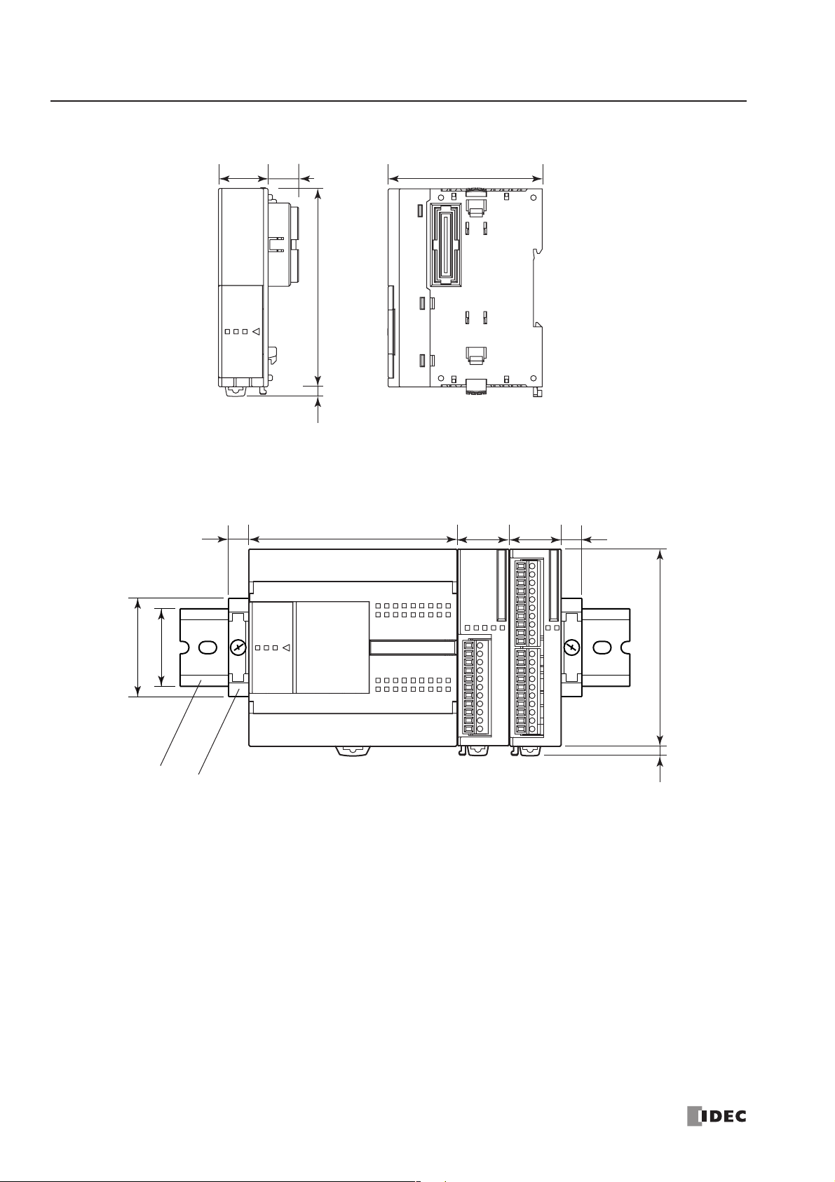
2: MODULE SPECIFICATIONS
2-74 « FC4A MICROSMART USER’S MANUAL »
Communication Modules FC4A-HPC1, FC4A-HPC2, FC4A-HPC3
Example: The following figure illustrates a system setup consisting of the all-in-one 24-I/O type CPU module, an 8-point
relay output module, and a 16-point DC input module mounted on a 35-mm-wide DIN rail using BNL6P mounting clips.
All dimensions in mm.
*8.5 mm when the clamp is pulled out.
95.09.0
35.0
45.0
23.5 23.5 9.0
4.5* 90.0
BNL6P Mounting Clip
DIN Rail
22.5 13.9 70.0
90.04.5*
*8.5 mm when the clamp is pulled out.
Page 95
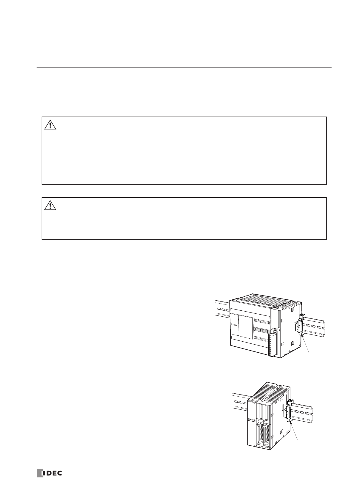
« FC4A MICROSMART USER’S MANUAL » 3-1
3: INSTALLATION AND WIRING
Introduction
This chapter describes the methods and precautions for installing and wiring MicroSmart modules.
Before starting installation and wiring, be sure to read “Safety Precautions” in the beginning of this manual and understand precautions described under Warning and Caution.
Installation Location
The MicroSmart must be installed correctly for optimum performance.
The
MicroSmart is designed for installation in a cabinet. Do not
install the MicroSmart outside a cabinet.
The environment for using the MicroSmart is “Pollution degree 2.”
Use the
MicroSmart in environments of pollution degree 2 (accord-
ing to IEC 60664-1).
Make sure that the operating temperature does not drop below 0°C
or exceed 55°C. If the temperature does exceed 55°C, use a fan or
cooler.
Mount the MicroSmart on a vertical plane as shown at right.
To eliminate excessive temperature build-up, provide ample ventilation. Do not install the MicroSmart near, and especially above,
any device which generates considerable heat, such as a heater,
transformer, or large-capacity resistor. The relative humidity should
be above 30% and below 95%.
The MicroSmart should not be exposed to excessive dust, dirt, salt,
direct sunlight, vibrations, or shocks. Do not use the MicroSmart in
an area where corrosive chemicals or flammable gases are present.
The modules should not be exposed to chemical, oil, or water
splashes.
Warning
Caution
• Turn off the power to the MicroSmart before starting installation, removal, wiring, maintenance,
and inspection of the MicroSmart. Failure to turn power off may cause electrical shocks or fire
hazard.
• Emergency stop and interlocking circuits must be configured outside the MicroSmart. If such a
circuit is configured inside the MicroSmart, failure of the MicroSmart may cause disorder of the
control system, damage, or accidents.
• Special expertise is required to install, wire, program, and operate the MicroSmart. People with-
out such expertise must not use the MicroSmart.
• Prevent metal fragments and pieces of wire from dropping inside the MicroSmart housing. Put a
cover on the MicroSmart modules during installation and wiring. Ingress of such fragments and
chips may cause fire hazard, damage, or malfunction.
• Do not touch the connector pins with hand, otherwise electrostatic discharge may damage the
internal elements.
All-in-One Type
Mounting Clip
BNL6P
Slim Type
Mounting Clip
BNL6P
Page 96

3: INSTALLATION AND WIRING
3-2 « FC4A MICROSMART USER’S MANUAL »
Assembling Modules
The following example demonstrates the procedure for assembling the all-in-one 24-I/O type CPU module and an I/O
module together. When assembling slim type CPU modules, take the same procedure.
1. When assembling an input or output module,
remove the expansion connector seal from the
24-I/O type CPU module.
2. Place the CPU module and I/O module side by side. Put the
expansion connectors together for easy alignment.
3. With the expansion connectors aligned correctly and the
blue unlatch button in the down position, press the CPU
module and I/O module together until the latches click to
attach the modules together firmly. If the unlatch button is
in the up position, push down the button to engage the
latches.
Disassembling Modules
1. If the modules are mounted on a DIN rail, first remove the
modules from the DIN rail as described on page 3-7.
2. Push up the blue unlatch button to disengage the latches,
and pull the modules apart as shown. When disassembling
slim type CPU modules, take the same procedure.
Unlatch Button
Caution
• Assemble MicroSmart modules together before mounting the modules onto a DIN rail. Attempt
to assemble modules on a DIN rail may cause damage to the modules.
• Turn off the power to the MicroSmart before assembling the modules. Failure to turn power off
may cause electrical shocks.
Caution
• Remove the MicroSmart modules from the DIN rail before disassembling the modules. Attempt
to disassemble modules on a DIN rail may cause damage to the modules.
• Turn off the power to the MicroSmart before disassembling the modules. Failure to turn power
off may cause electrical shocks.
Unlatch Button
Page 97

3: INSTALLATION AND WIRING
« FC4A MICROSMART USER’S MANUAL » 3-3
Installing the HMI Module
The optional HMI module (FC4A-PH1) can mount on any all-in-one type CPU module, and also on the HMI base module
mounted next to any slim type CPU module. For specifications of the HMI module, see page 2-60. For details about operating the HMI module, see page 5-32.
All-in-One Type
1. Remove the HMI connector cover from the CPU module. Locate the HMI connector inside the CPU module.
2. Push the HMI module into the HMI module connector in the CPU module until the latch clicks.
Slim Type
1. When using the HMI module with the slim type CPU mod-
ule, prepare the optional HMI base module (FC4A-HPH1).
See page 2-61.
2. Locate the HMI connector inside the HMI base module.
Push the HMI module into the HMI connector in the HMI
base module until the latch clicks.
3. Remove the communication connector cover from the slim
type CPU module. See page 3-6.
4. Place the HMI base module and CPU module side by side.
With the communication connectors aligned correctly and
the blue unlatch button in the down position, press the HMI
base module and CPU module together until the latches
click to attach the modules together firmly. If the unlatch
button is in the up position, push down the button to engage
the latches.
HMI Module
HMI Connector
Caution
• Turn off the power to the MicroSmart before installing or removing the HMI module to prevent
electrical shocks.
• Do not touch the connector pins with hand, otherwise electrostatic discharge may damage the
internal elements.
HMI Base Module
HMI Module
Slim Type CPU Module
Unlatch Button Communication Connector Cover
Page 98

3: INSTALLATION AND WIRING
3-4 « FC4A MICROSMART USER’S MANUAL »
Removing the HMI Module
This section describes the procedures for removing the HMI module from the optional HMI base module mounted next to
any slim type CPU module.
1. Insert a thin flat screwdriver (ø3.0 mm maximum) between the gap
on top of the HMI module until the tip of the screwdriver bottoms.
2. While turning the screwdriver in the direction as shown, disengage
the latch on the HMI module and pull out the HMI module.
3. Remove the HMI module from the HMI base module.
Caution
• Turn off the power to the MicroSmart before installing or removing the HMI module to prevent
electrical shocks.
• Do not touch the connector pins with hand, otherwise electrostatic discharge may damage the
internal elements.
Latch
Page 99

3: INSTALLATION AND WIRING
« FC4A MICROSMART USER’S MANUAL » 3-5
Removing the Terminal Blocks
This section describes the procedures for removing the terminal blocks from slim type CPU modules FC4A-D20RK1 and
FC4A-D20RS1.
1. Before removing the terminal blocks, disconnect all
wires from the terminal blocks.
Remove the shorter terminal block on the left first,
then remove the longer one on the right.
2. When removing the longer terminal block, hold the
center of the terminal block, and pull it out straight.
3. Do not pull one end of the longer terminal block,
otherwise the terminal block may be damaged.
Caution
• Turn off the power to the MicroSmart before installing or removing the terminal blocks to pre-
vent electrical shocks.
• Use the correct procedures to remove the terminal blocks, otherwise the terminal blocks may be
damaged.
First, remove the
shorter terminal
block.
FC4A-D20RK1 and FC4A-D20RS1
Next, remove the
longer terminal
block.
Page 100
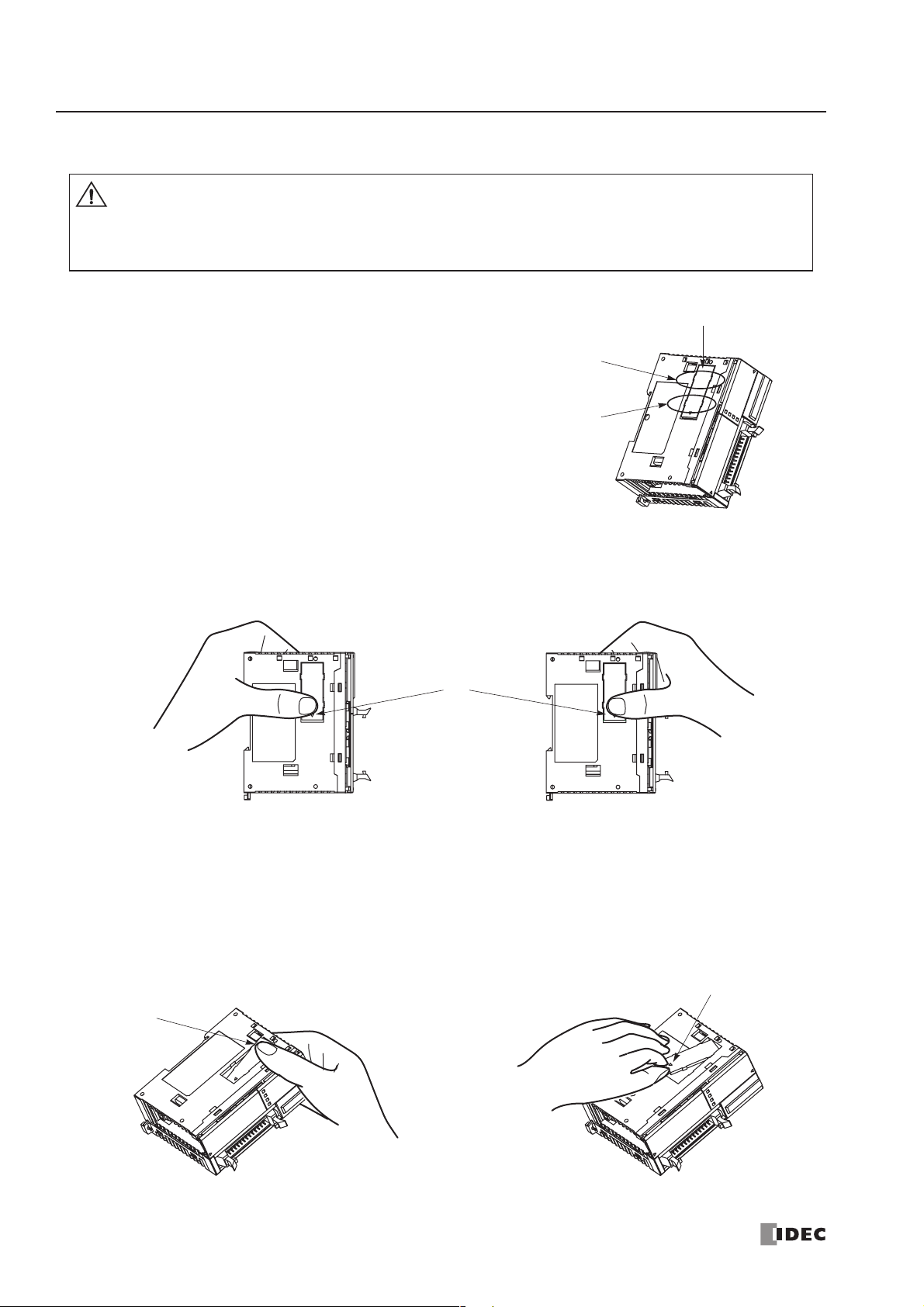
3: INSTALLATION AND WIRING
3-6 « FC4A MICROSMART USER’S MANUAL »
Removing the Communication Connector Cover
Before mounting a communication module or HMI base module next
to the slim type CPU module, the communication connector cover
must be removed from the CPU module. Break the communication
connector cover on the slim type CPU module as described below.
1. Carefully push in the communication connector cover at position (1) to break bridges A as shown in either figure
below.
2. The other end (2) of the communication connector cover will come out as shown at left below. Push in this end.
3. Then, the opposite end (3) will come out. If the end does not come out, insert a thin screwdriver into the gap and pull
out the end (3).
Hold the communication connector cover at (3), and pull off the communication connector cover to break bridges B.
C
(1)
Caution
• When using a thin screwdriver to pull out the communication connector cover, insert the screw-
driver carefully and do not damage the electronic parts inside the CPU module.
• When first pushing in the communication connector cover to break, take care not to injure your
finger.
ommunication
Connector Cover
Bridges B
Bridges A
(3)
(2)
 Loading...