

Page 1
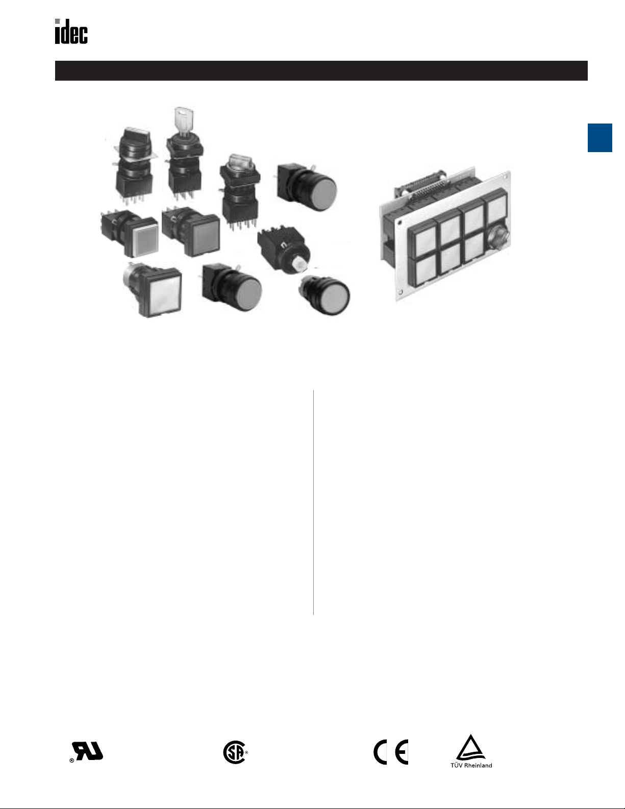
Oiltight Switches and Pilot Devices LW Series: 22mm
LW Series — Switches and Pilot Devices: 22mm
A
Switches & Pilot Devices
LW Series offer flexibility in space-saving package
Key features include:
• PC board mount, solder or screw terminal
•Collective mounting saves space
•Non-reflective lens
•Highly visible marking plate
•Tamper proof construction
•Light touch reduces strain
•Gold or silver contacts
•Removable contacts simplify wiring
and facilitate PCB applications
LW Series switches and pilot lights can be mounted collectively on 1.0"
centers. Combined with pcb terminals and locking lever removable
contacts, this eases manufacture of pre-fab pushbutton arrays (as
pictured). PC Board tracing/soldering of contacts can be done in tandem
with panel cutting/operator installation.
All LW series units mount by means of a locking ring that comes on from
the rear of the panel, as such they can not be removed from outside the
panel and are relatively tamperproof.
Combining the snap action and tactile feel of miniature commercial
pushbuttons with the size and ruggedness of industrial pushbuttons,
LW pushbuttons are a unique solution to many applications.
Choose from standard silver contacts or low-level gold plated contacts.
Ter minals available in .110" solder tab, M3 screw, or pcb pins.
UL Recognized
File # E55996
www.idec.com USA: (800) 262-IDEC or (408) 747-0550, Canada (888) 317-IDEC A-57
CSA Certified
File No. LR21451
Registration
No. J9551801
Page 2
LW Series: 22mm Oiltight Switches and Pilot Devices
Specifications
Operating Temperature
Storage Temperature
A
Operating Humidity
Contact Resistance
Insulation Resistance
Dielectric Strength
Switch Unit
Illumination Unit Between live part and ground: 2,500V AC, 1 minute
Vibration Resistance
Shock Resistance
Mechanical Life
Specifications
Electrical Life
Degree of Protection
Switches & Pilot Devices
Insulation Voltage
Materials
Terminal Style
Lenses polyarylate
Operators polyacetate
Marking Plates acrylic resin
–25 to +60°C (without freezing) LED illuminated type: –25 to +50°C
–40 to +80°C
45 to 85% RH
50mΩ maximum (initial value)
100MΩ minimum (500V DC megger)
Between live part and ground: 2,500V AC, 1 minute
Between terminals of different poles: 2,500V AC, 1 minute
Between terminals of the same pole: 1,000V AC, 1 minute
Operating extremes: 5 to 55Hz, Amplitude 1.0mm p-p
Damage limits: 1,000 m/sec2 (Approx. 100G)
Operating extremes: 100 m/sec
Momentary: 1,000,000 operations minimum
Maintained: 500,000 operations minimum
Selectors: 250,000 operations minimum
Momentary: 100,000 operations minimum (at 1,800 operations/hour)
Maintained/Selector: 100,000 operations minimum (at 900 operations/hour)
Watertight/oiltight IP65 (IEC Pub529) (except key selectors)
250VAC/DC
.110" Solder tab/quick connect
PC board terminal (gold contacts only)
Screw terminal (DPDT units only)
2
(Approx. 10G)
Contact Material Thermal Current Contact Rating Remarks
Gold-clad cross-bar 3A
Silver Contact 5A
Contact Ratings
30VDC/0.1A resistive
125VAC/0.1A resistive
30VDC/2A resistive
30VDC/1A inductive
125VAC/3A resistive(50/60Hz)
125VAC/2A inductive (50/60Hz)
125VDC/0.4A resistive
125VDC/0.2A inductive
250VAC/2A resistive(50/60Hz)
250VAC/1.5A inductive (50/60Hz)
Lamp Ratings
Voltage Current/Wattage
6V AC/DC ±10% 17mA max
12V AC/DC ±10% 11mA max
24V AC/DC ±10% 11mA max
LED
120V AC ±10% 10mA max
240V AC ±10% 10mA max
6.3V AC/DC ±5% 1W
12V AC/DC ±10% 1W
Minimum applicable load (reference value): 5V, 1mA AC/DC.
(Applicable range is subject to the operating condition and load.)
AC inductive load: PF=0.6 to 0.7,
DC inductive load: L/R=7ms maximum.
UL Recognized
File # E55996
CSA Certified
File No. LR21451
Registration
No. J9551801
24V AC/DC ±10%
Incandescent
LED lamps contains a built-in current-limiting resistor and reverse polarity protection diode.
1W
A-58 www.idec.com USA: (800) 262-IDEC or (408) 747-0550, Canada (888) 317-IDEC
Page 3
Oiltight Switches and Pilot Devices LW Series: 22mm
① Button Color Code
Color Code
Black B
Green G
Red R
Blue S
White W
Yellow Y
(DC),
)
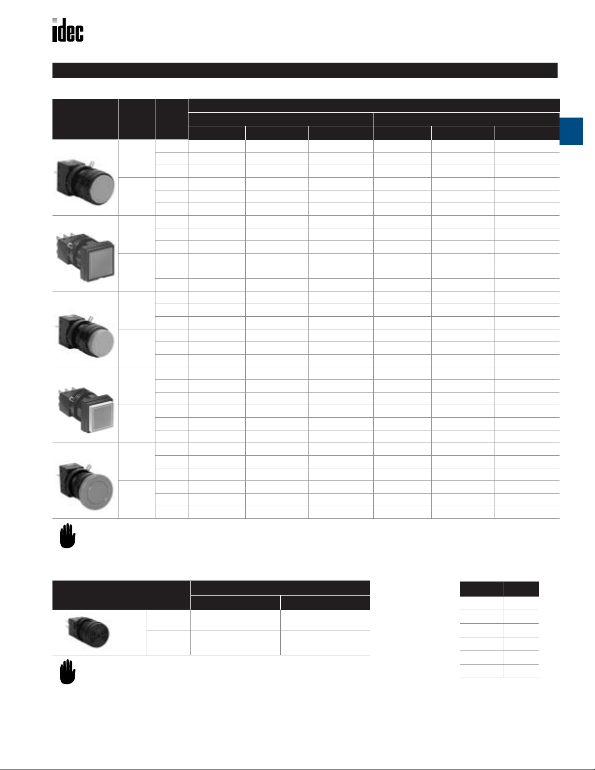
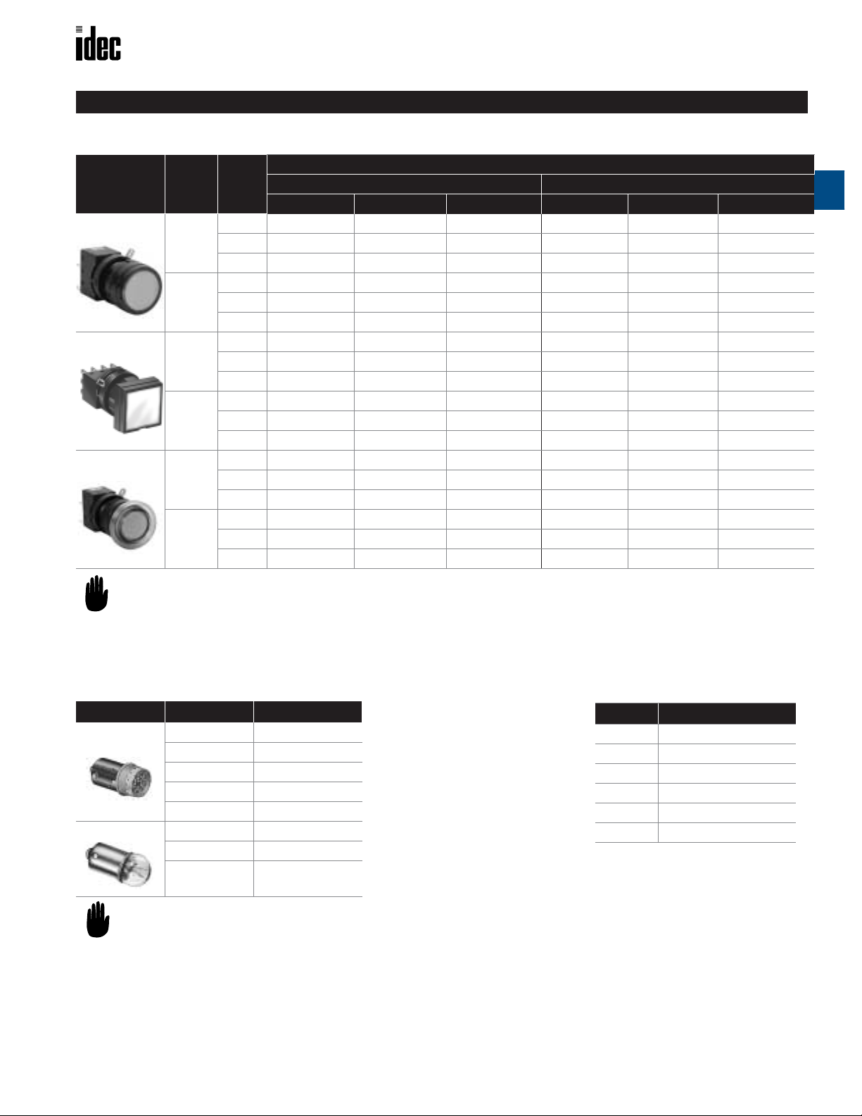
Part Numbers: LW1B/LW2B Pushbuttons
Style
Round Flush
Square Flush
Round Extended
Square Extended
Mushroom
1.In place of ①, specify Button Color Code from table below.
2.For sub-assembly part numbers, see page A-60.
3.For dimensions, see page A-69.
4.For accessories, see page A-68.
Contact
Material
Gold
Silver
Gold
Silver
Gold
Silver
Gold
Silver
Gold
Silver
Contact
Solder/Tab PC Board Screw Solder/Tab PC Board Screw
SPDT LW1B-M1C1-① LW1B-M1C1V-① —LW1B-A1C1-① LW1B-A1C1V-① —
DPDT LW1B-M1C2-① LW1B-M1C2V-① LW1B-M1C2M-① LW1B-A1C2-① LW1B-A1C2V-① LW1B-A1C2M-①
3PDT LW1B-M1C3-① LW1B-M1C3V-① —LW1B-A1C3-① LW1B-A1C3V-① —
SPDT LW1B-M1C5-① ——LW1B-A1C5-① ——
DPDT LW1B-M1C6-① —LW1B-M1C6M-① LW1B-A1C6-① —LW1B-A1C6M-①
3PDT LW1B-M1C7-① ——LW1B-A1C7-① ——
SPDT LW2B-M1C1-① LW2B-M1C1V-① —LW2B-A1C1-① LW2B-A1C1V-① —
DPDT LW2B-M1C2-① LW2B-M1C2V-① LW2B-M1C2M-① LW2B-A1C2-① LW2B-A1C2V-① LW2B-A1C2M-①
3PDT LW2B-M1C3-① LW2B-M1C3V-① —LW2B-A1C3-① LW2B-A1C3V-① —
SPDT LW2B-M1C5-① ——LW2B-A1C5-① ——
DPDT LW2B-M1C6-① —LW2B-M1C6M-① LW2B-A1C6-① —LW2B-A1C6M-①
3PDT LW2B-M1C7-① ——LW2B-A1C7-① ——
SPDT LW1B-M2C1-① LW1B-M2C1V-① —LW1B-A2C1-① LW1B-A2C1V-① —
DPDT LW1B-M2C2-① LW1B-M2C2V-① LW1B-M2C2M-① LW1B-A2C2-① LW1B-A2C2V-① LW1B-A2C2M-①
3PDT LW1B-M2C3-① LW1B-M2C3V-① —LW1B-A2C3-① LW1B-A2C3V-① —
SPDT LW1B-M2C5-① ——LW1B-A2C5-① ——
DPDT LW1B-M2C6-① —LW1B-M2C6M-① LW1B-A2C6-① —LW1B-A2C6M-①
3PDT LW1B-M2C7-① ——LW1B-A2C7-① ——
SPDT LW2B-M2C1-① LW2B-M2C1V-① —LW2B-A2C1-① LW2B-A2C1V-① —
DPDT LW2B-M2C2-① LW2B-M2C2V-① LW2B-M2C2M-① LW2B-A2C2-① LW2B-A2C2V-① LW2B-A2C2M-①
3PDT LW2B-M2C3-① LW2B-M2C3V-① —LW2B-A2C3-① LW2B-A2C3V-① —
SPDT LW2B-M2C5-① ——LW2B-A2C5-① ——
DPDT LW2B-M2C6-① —LW2B-M2C6M-① LW2B-A2C6-① —LW2B-A2C6M-①
3PDT LW2B-M2C7-① ——LW2B-A2C7-① ——
SPDT LW1B-M3C1-① LW1B-M3C1V-① —LW1B-A3C1-① LW1B-A3C1V-① —
DPDT LW1B-M3C2-① LW1B-M3C2V-① LW1B-M3C2M-① LW1B-A3C2-① LW1B-A3C2V-① LW1B-A3C2M-①
3PDT LW1B-M3C3-① LW1B-M3C3V-① —LW1B-A3C3-① LW1B-A3C3V-① —
SPDT LW1B-M3C5-① ——LW1B-A3C5-① ——
DPDT LW1B-M3C6-① —LW1B-M3C6M-① LW1B-A3C6-① —LW1B-A3C6M-①
3PDT LW1B-M3C7-① ——LW1B-A3C7-① ——
Non-Illuminated Pushbuttons (Assembled)
Part Number
Momentary Maintained (Latching)
A
Switches & Pilot Devices
Part Numbers: Buzzers
12-24V AC/DC+/- 10%
80 dB (at 0.1m)
7mA
www.idec.com USA: (800) 262-IDEC or (408) 747-0550, Canada (888) 317-IDEC A-59
Style
20mA (AC
Part Number
Solder Tab PCB
Basic LW1Z-1X4 LW1Z-1X4V
With LED LW1Z-1X4D LW1Z-1X4DV
Page 4
LW Series: 22mm Oiltight Switches and Pilot Devices
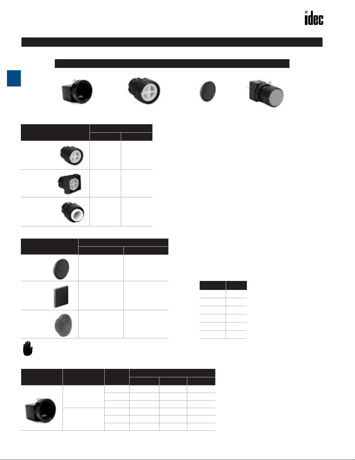
Non-Illuminated Pushbuttons (Sub-Assembled)
Contact Block + Operator + Button = Completed Unit
A
Part Numbers: Operators
Style
Round
Square
Switches & Pilot Devices
Part Number
Momentary Maintained
LW1B-M0 LW1B-A0
LW2B-M0 LW2B-A0
Mushroom
LW1B-M0L LW1B-A0L
Part Numbers: Buttons
Type
Flush Extended
Part Number
Round
LW1A-B1-① LW1A-B2-①
Square
LW2A-B1-① LW2A-B2-①
Mushroom
—LW1A-B3-①
In place of ①, specify Button Color Code from table at
right.
Part Numbers: Contact Blocks
Appearance Contact Material Contact
SPDT LW-C1 LW-C1V —
Gold
Silver
DPDT LW-C2 LW-C2V LW-C2M
3PDT LW-C3 LW-C3V —
SPDT LW-C5 — —
DPDT LW-C6 — LW-C6M
3PDT LW-C7 — —
① Button Color Code
Color Code
Black B
Green G
Red R
Blue S
White W
Yellow Y
Part Number
Solder/Tab PC Board Screw
A-60 www.idec.com USA: (800) 262-IDEC or (408) 747-0550, Canada (888) 317-IDEC
Page 5
Oiltight Switches and Pilot Devices LW Series: 22mm
➁
LED and Incandescent Illuminated Pushbuttons (Assembled)
Part Numbers: LW1L/LW2L Illuminated Pushbuttons (LED and Incandescent)
Style
Contact
Material
Contact
Solder/Tab PC Board Screw Solder/Tab PC Board Screw
Round
Square
Mushroom
1. In place of
2. Lamps must be ordered separately for all illuminated pushbuttons.
3. For marking plate size and engraving area, see page A-73.
4.For sub-assembly part numbers, see page A-62.
5.For dimensions, see page A-69.
5.For accessories, see page A-68.
Gold
Silver
Gold
Silver
Gold
Silver
SPDT
DPDT
3PDT
SPDT
DPDT
3PDT
SPDT
DPDT
3PDT
SPDT
DPDT
3PDT
SPDT
DPDT
3PDT
SPDT
DPDT
3PDT
, specify the Lens Color Code from table below.
LW1L-M1C10LW1L-M1C20LW1L-M1C30LW1L-M1C50LW1L-M1C60LW1L-M1C70LW2L-M1C10LW2L-M1C20LW2L-M1C30LW2L-M1C50LW2L-M1C60LW2L-M1C70LW1L-M3C10LW1L-M3C20LW1L-M3C30LW1L-M3C50LW1L-M3C60LW1L-M3C70-
➁ LW1L-M1C10V-➁
➁ LW1L-M1C20V-➁ LW1L-M1C20M-➁ LW1L-A1C20-➁ LW1L-A1C20V-➁ LW1L-A1C20M-➁
➁ LW1L-M1C30V-➁
➁
➁
➁
➁ LW2L-M1C10V-➁
➁ LW2L-M1C20V-➁ LW2L-M1C20M-➁ LW2L-A1C20-➁ LW2L-A1C20V-➁ LW2L-A1C20M-➁
➁ LW2L-M1C30V-➁
➁
➁
➁
➁ LW1L-M3C10V-➁
➁ LW1L-M3C20V-➁ LW1L-M3C20M-➁ LW1L-A3C20-➁ LW1L-A3C20V-➁ LW1L-A3C20M-➁
➁ LW1L-M3C30V-➁
➁
➁
➁
Momentary Maintained (Latching)
—
—
——
—
——
——
—
——
——
—
——
LW1L-M1C60M-
—
—
LW2L-M1C60M-
—
—
LW1L-M3C60M-
Part Number
➁ LW1L-A1C60-➁
➁ LW2L-A1C60-➁
➁ LW1L-A3C60-➁
LW1L-A1C10-
LW1L-A1C30LW1L-A1C50-
LW1L-A1C70LW2L-A1C10-
LW2L-A1C30LW2L-A1C50-
LW2L-A1C70LW1L-A3C10-
LW1L-A3C30LW1L-A3C50-
LW1L-A3C70-
➁ LW1L-A1C10V-➁
➁ LW1L-A1C30V-➁
——
➁
—
——
➁
➁ LW2L-A1C10V-➁
➁ LW2L-A1C30V-➁
——
➁
—
——
➁
➁ LW1L-A3C10V-➁
➁ LW1L-A3C30V-➁
——
➁
—
——
➁
—
—
LW1L-A1C60M-
—
—
LW2L-A1C60M-
—
—
LW1L-A3C60M-
A
Switches & Pilot Devices
➁
➁
➁
Part Numbers: Lamps (not included in assemblies)
Type Voltage Part Number
LED
Incandescent
1.In place of ➁, specify the LED Color Code.
2.The LED contains a current-limiting resistor
and reverse polarity protection diode.
6V AC/DC±10% LSTD-6➁
12V AC/DC±10% LSTD-1➁
24V AC/DC±10% LSTD-2➁
120V AC±10% LSTD-H2➁
240V AC ±10% LSTD-M4➁
6.3V AC/DC IS-6
12V AC/DC IS-12
24V AC/DC IS-24
➁ Lens/LED Color Code
Color Code
Amber A
Green G
Red R
Blue S
White W
Yellow Y
www.idec.com USA: (800) 262-IDEC or (408) 747-0550, Canada (888) 317-IDEC A-61
Page 6
LW Series: 22mm Oiltight Switches and Pilot Devices
LED and Incandescent Illuminated Pushbuttons (Sub-Assembled)
Contact Block + Operator + Lamp + Lens = Completed Unit
A
Part Numbers: Operators Part Numbers: Lenses
Style
Part Number
Momentary Maintained
Round
LW1L-M0 LW1L-A0
Square
Switches & Pilot Devices
LW2L-M0 LW2L-A0
Mushroom
LW1B-M0L LW1B-A0L
Type
Round
Square
Mushroom
In place of ➁, specify Lens Color Code from table below.
Part Number
Flush
LW1A-L1-➁
LW2A-L1-➁
LW1A-L3-➁
Part Numbers: Contact Blocks
Appearance Contact Material Contact
SPDT LW-C10 LW-C10V —
Gold
Silver
DPDT LW-C20 LW-C20V LW-C20M
3PDT LW-C30 LW-C30V —
SPDT LW-C50 — —
DPDT LW-C60 — LW-C60M
3PDT LW-C70 — —
Part Numbers: Lamps (not included in assemblies)
Type Voltage Part Number
LED
Incandescent
1.In place of ➁, specify the LED Color Code.
2.The LED contains a current-limiting resistor
and reverse polarity protection diode.
6V AC/DC±10% LSTD-6➁
12V AC/DC±10% LSTD-1➁
24V AC/DC±10% LSTD-2➁
120V AC±10% LSTD-H2➁
240V AC ±10% LSTD-M4➁
6.3V AC/DC IS-6
12V AC/DC IS-12
24V AC/DC IS-24
Part Number
Solder/Tab PC Board Screw
➁ LED/Lens Color Code
Color Code
Amber A
Green G
Red R
Blue S
White W
Yellow Y
A-62 www.idec.com USA: (800) 262-IDEC or (408) 747-0550, Canada (888) 317-IDEC
Page 7

Oiltight Switches and Pilot Devices LW Series: 22mm
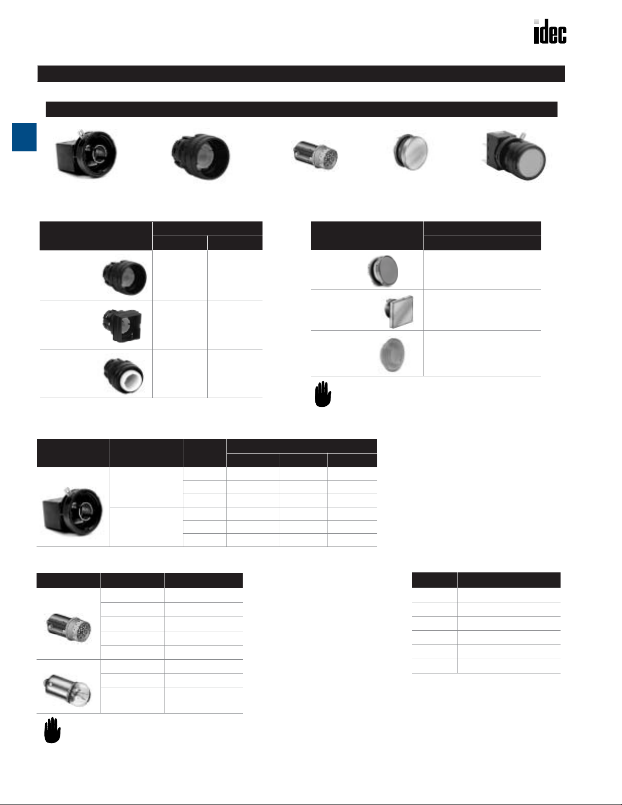
LED and Incandescent Pilot Lights (Assembled)
Part Numbers: LW1P/LW2P Pilot Lights
Type Style
Round
Removable
Terminal Pilot Light
Square
Part Number
Solder/Tab PC Board Screw
—
LW1P-1C00V-
➁
A
Switches & Pilot Devices
—
Round
Monolithic
Pilot Light
1. In place of ➁, specify the Lens Color Code from table below.
2. For marking plate size and engraving area, see page A-73.
3. Lamps must be ordered separately, see table below.
4.For sub-assembly part numbers, see page A-64.
5.For dimensions, see page A-69.
6.For accessories, see page A-68.
Square
Part Numbers: Lamps (not included in assemblies)
Type Voltage Part Number
LED
Incandescent
6V AC/DC±10% LSTD-6➁
12V AC/DC±10% LSTD-1➁
24V AC/DC±10% LSTD-2➁
120V AC±10% LSTD-H2➁
240V AC ±10% LSTD-M4➁
6.3V AC/DC IS-6
12V AC/DC IS-12
—
LW1P-10-
LW2P-10-➁
LW2P-1C00V-
➁
➁
—
—
—
LW1P-10M-
LW2P-10M-
➁
➁
➁ Lens/LED Color Code
Color Code
Amber A
Green G
Red R
Blue
White W
Yellow Y
S
24V AC/DC IS-24
1.In place of ➁, specify the LED Color Code.
2.The LED contains a current-limiting resistor
and reverse polarity protection diode.
www.idec.com USA: (800) 262-IDEC or (408) 747-0550, Canada (888) 317-IDEC A-63
Page 8

LW Series: 22mm Oiltight Switches and Pilot Devices
1
LED and Incandescent Pilot Lights (Sub-Assembled)
Removable Terminal* + Operator + Lamp + Lens = Completed Unit
A
* Removable terminals are applicable for PCB terminated types only.
Part Numbers: Pilot Light Operators
Style
Round
Square
Switches & Pilot Devices
Solder PC Board Screw
LW1P-00
LW2P-00
Termination
LW1P-0
LW2P-0
†
†
LW1P-00M
LW2P-00M
. † Requires LW-C00V removable terminals in addition to operator.
2. Solder and screw terminals are monolithic (they do not use a removable terminal block).
Part Numbers: Lenses
Type Part Number
Round
LW1A-P1-➁
Square
LW2A-P1-➁
In place of ➁, specify Lens Color Code.
Part Numbers: Lamps (not included in assemblies)
Type Voltage Part Number
LED
Incandescent
6V AC/DC±10% LSTD-6➁
12V AC/DC±10% LSTD-1➁
24V AC/DC±10% LSTD-2➁
120V AC±10% LSTD-H2➁
240V AC ±10% LSTD-M4➁
6.3V AC/DC IS-6
12V AC/DC IS-12
➁ LED/Lens Color Code
Color Code
Amber A
Green G
Red R
Blue S
White W
Yellow Y
24V AC/DC IS-24
1.In place of ➁, specify the LED Color Code.
2.The LED contains a current-limiting resistor
and reverse polarity protection diode.
A-64 www.idec.com USA: (800) 262-IDEC or (408) 747-0550, Canada (888) 317-IDEC
Page 9

1
Oiltight Switches and Pilot Devices
Selector and Keylock Switches (Assembled)
Part Numbers: LW1S Selector Switches
Style
Round
1.Knob color: Black; Directional Indication Color: White
2.For contact operation, see next page.
3.For sub-assembly part numbers, see page A-67.
Part Numbers: LW1K Keylock Selector Switches
Style
Round
. Every key selector uses an identical key.
2. The key is removable in all positions.
3. If a different configuration is required, contact an IDEC representative for more information.
4.For contact operation, see next page.
5.For sub-assembly part numbers, see page A-67.
Position Contact Material Contact
90° 2-position
maintained
LR
45° 3-position
maintained
C
LR
Gold
Silver
Gold
Silver
SPDT LW1S-2C1 LW1S-2C1V —
DPDT LW1S-2C2 LW1S-2C2V LW1S-2C2M
3PDT LW1S-2C3 LW1S-2C3V —
SPDT LW1S-2C5 — —
DPDT LW1S-2C6 — LW1S-2C6M
3PDT LW1S-2C7 — —
DPDT LW1S-3C2 LW1S-3C2V LW1S-3C2M
3PDT LW1S-3C3 LW1S-3C3V —
DPDT LW1S-3C6 — LW1S-3C6M
3PDT LW1S-3C7 — —
Position Contact Material Contact
SPDT LW1K-2C1A LW1K-2C1VA —
90° 2-position
maintained
LR
45° 3-position
maintained
C
LR
Gold
Silver
Gold
Silver
DPDT LW1K-2C2A LW1K-2C2VA LW1K-2C2MA
3PDT LW1K-2C3A LW1K-2C3VA —
SPDT LW1K-2C5A — —
DPDT LW1K-2C6A — LW1K-2C6MA
3PDT LW1K-2C7A — —
DPDT LW1K-3C2A LW1K-3C2VA LW1K-3C2MA
3PDT LW1K-3C3A LW1K-3C3VA —
DPDT LW1K-3C6A — LW1K-3C6MA
3PDT LW1K-3C7A — —
Solder/Tab PC Board Screw
LW Series: 22mm
Part Number
A
Switches & Pilot Devices
Part Number
Solder/Tab PC Board Screw
Part Numbers: LW1F LED and Incandescent Illuminated Selector Switches
➁
➁
➁
➁
➁
➁
➁
➁
➁
➁
Part Numbers
LW1F-2C10VLW1F-2C20VLW1F-2C30V-
LW1F-3C20VLW1F-3C30V-
➁
➁
➁
——
—
——
➁
➁
—
——
—
LW1F-2C20M-
—
LW1F-2C60M-
LW1F-3C20M-
—
LW1F-3C60M-
➁
➁
➁
➁
Style
Round
1. In place of ➁, specify color code. See previous page for color codes.
2. Lamps must be ordered separately for all illuminated pushbuttons. See previous page.
3.For contact operation, see next page.
4.For sub-assembly part numbers, see page A-67.
www.idec.com
Position Contact Material Contact
SPDT
90° 2-position
maintained
LR
45° 3-position
maintained
C
LR
Gold
Silver
Gold
Silver
DPDT
3PDT
SPDT
DPDT
3PDT
DPDT
3PDT
DPDT
3PDT
USA: (800) 262-IDEC or (408) 747-0550, Canada (888) 317-IDEC A-65
Solder/Tab PC Board Screw
LW1F-2C10LW1F-2C20LW1F-2C30LW1F-2C50LW1F-2C60LW1F-2C70LW1F-3C20LW1F-3C30LW1F-3C60LW1F-3C70-
Page 10

C
NO NC
Left Center Right
C
NO NCCNO NC
Left Center Right
NO NC
C
C
NO NCCNO NC
LW Series: 22mm
Contact Operation: Selector and Keylock Switches
Position
A
LR
90°
2-Position
Maintained
Switches & Pilot Devices
Contact
SPDT _
DPDT _
Left Center Right
NO NC
3PDT _
Left Center Right
NO NC
C
Left Right
NO NC
C
NO NC
Oiltight Switches and Pilot Devices
Contact Operations
Operator Position and Contact Position (Top View)
NO NC
C
Left Right
NO NC
C
NO NC
NO NC
C
NO NC
C
C
Left Right
NO NC
C
NO NC
C
DPDT
C
LR
45°
3-Position
Maintained
3PDT
C
NO NC
Left Center Right
NO NC
Terminal Arrangements (Bottom View): LW
3 pole illuminated 3 pole non-illuminated2 pole illuminated
Lamp
Terminal
(+)
Lamp
Terminal
(—)
SPDT has C, NO and NC only on the center. DPDT has C, NO, and NC only
on the right and left.
X1X2X2
NCNOC
NCNOC
NCNOC
C
C
NO NC
CC
❏
L and LW
Lamp
Terminal
(+)
Lamp
Terminal
(—)
Left Right
NO NC
C
Left Center Right
NO NC
C
❏
B Pushbuttons
X1X2
NO NC
NO NC
C
NCNOC
C
NO NC
C
NCNOC
Left Right
NO NC
C
NO NC
C
NCNOC
NCNOC
SPDT has C, NO and NC only on the
right. DPDT has C, NO, and NC only
on the right and center.
NCNOC
A-66
www.idec.com
USA: (800) 262-IDEC or (408) 747-0550, Canada (888) 317-IDEC
Page 11

Oiltight Switches and Pilot Devices
Selectors and Key Switches (Sub-Assembled)
Contact Block
*Lens for illuminated units only
Part Numbers: Operators
Unit Position Part Number
Non-Illuminated
Selector Switch
Key Switch
Illuminated
Selector Switch
* Lens must be purchased separately for illuminated units.
+ Operator + Lens* = Completed Unit
2-position LW1S-2Y
3-position LW1S-3Y
2-position LW1K-2A
3-position LW1K-3A
2-position LW1F-20*
3-position LW1F-30*
LW Series: 22mm
A
Switches & Pilot Devices
Part Numbers: Knob (Lens)
Style Part Number
Illuminated Selector Switches
LW1A-F-➁
In place of ➁, specify LED/Lens Color Code from table below.
Part Numbers: Contact Blocks
Appearance
Part Numbers: Lamps (not included in assemblies)
Type
LED
Incandescent
Voltage Part Number
6V AC/DC±10% LSTD-6 ➁
12V AC/DC±10% LSTD-1 ➁
24V AC/DC±10% LSTD-2 ➁
120V AC±10% LSTD-H2 ➁
240V AC ±10% LSTD-M4 ➁
6.3V AC/DC IS-6
12V AC/DC IS-12
Style Contact Material Contact
Gold
Illuminated
Selector Switches
Silver
Gold
Non-Illuminated
Selector Switches
Silver
Part Number
Solder/Tab PC Board Screw
SPDT LW-C10 LW-C10V —
DPDT LW-C20 LW-C20V LW-C20M
3PDT LW-C30 LW-C30V —
SPDT LW-C50 — —
DPDT LW-C60 — LW-C60M
3PDT LW-C70 — —
SPDT LW-C1 LW-C1V —
DPDT LW-C2 LW-C2V LW-C2M
3PDT LW-C3 LW-C3V —
SPDT LW-C5 — —
DPDT LW-C6 — LW-C6M
3PDT LW-C7 — —
➁ LED/Lens Color Code
Color Code
Amber A
Green G
Red R
Blue S
White W
Yellow Y
24V AC/DC IS-24
1.In place of ➁, specify the LED Color Code.
2.The LED contains a current-limiting resistor
and reverse polarity protection diode.
www.idec.com
USA: (800) 262-IDEC or (408) 747-0550, Canada (888) 317-IDEC A-67
Page 12

0.137"
g
LW Series: 22mm
Style
Ring Wrench (optional)
A
Lamp Holder Tool (optional)
Terminal Cover
(for solder tab terminal)
Terminal Cover
(for screw terminal)
Switches & Pilot Devices
Terminal Cover
(for short body pilot light with solder tab terminal)
Oiltight Switches and Pilot Devices
Accessories — LW Series
Description/Usage Part Number
1. Metallic tool used for tightening the plastic locking ring when installing the LW series on a panel.
2. Tightening torque should not exceed 1.2N-m
(12 kgf-cm) when tightening a locking ring.
Rubber tool used for replacing incandescent or LED lamps installed in
illuminated switches and pilot lights and pilot lights
ø0.452"
(ø11.6mm)
2.301" (59mm)
Nylon cover for pushbuttons and selectors with solder terminals snaps
onto contact block.
(Insert the lead wires through terminal
cover holes before wiring.)
Nylon cover for pushbuttons and selectors for screw terminals snaps
onto contact block.
(Insert the lead wires through terminal
cover holes before wiring.)
Nylon cover for short body pilot lights with solder terminals. LW-PVL
ø0.546"
(ø14mm)
LW9Z-T1
OR-55
LW-VL2
LW-VL2M
Terminal Cover
(for short body pilot light with screw terminal)
Rubber Mounting Hole Plug
Metallic Mounting
Hole Plug
Replacement
Marking Plates
Anti-Rotation Ring
Replacement
Keys
Nylon cover for short body pilot lights with screw terminals. LW-PVLM
Black rubber plug fills unused 22mm panel cutouts.
ø1.131" (ø29mm)
0.137"
(3.5mm)
1. Used for plugging unnecessary mounting holes in the panel. Tighten
the attached locking ring to a torque of 1.2N-m (12kgf-cm) maximum
2. Degree of Protection: IP66
White plastic engraving plate for use on all illuminated units (included
in each lens).
May be used to capture printed mylar insert (not supplied by IDEC)
under lens face.
Prevents rotation of switches in panel.
(included with all selector and key switches only)
One pair of keys. (#231) KG9Z-SK-231PN02
0.468"
(12mm)
ø1.0" (ø25.8mm)
(3.5mm)
ø0.975" (ø25mm)
0.117" (3mm)
Locking Rin
OB-31
LW9Z-BM
LW9Z-P1-W (round)
LW9Z-P2-W (square)
ALW3B (mushroom)
LW9Z-L
Replacement
Locking Ring
For replacement lamps, see previous page.
A-68
www.idec.com
Use to secure operator to panel.
(included with all assembled switches and operators)
USA: (800) 262-IDEC or (408) 747-0550, Canada (888) 317-IDEC
LW9Z-LN
Page 13

LW
❏
L & LW
M3 Screw Terminal
Terminal Cover
6.2
8.2
2.0
23.2
Oiltight Switches and Pilot Devices
Dimensions: Pushbuttons
❏
B: Illuminated & Non-Illuminated Pushbuttons
Terminal Cover
LW-VL2
LW-VL2M
4.85
R18
NCNO
C
LOCK
6.8
6.8
66
18.2
1.2
∗
16.2
Solder/Tab Terminal
Solder/Tab Terminal
Width 2.8 × 0.5t
Solder/Tab TerminalScrew Terminal PC Board Terminal
6.8
4.85
6.8
54.9
LOCK
R18
16.2
25.4
Screw Terminal
53.5 36
PC Board Terminal
PC Board Terminal
Width 0.8 × 0.5t
1.2
55
5.4
X1
NC
X2
NO
C
X2
25
Gasket
Locking Ring
OTP
47
LOCK
R18
25
26.5
8.5 11.7
2.6
9369
Panel Thickness: 0.8 to 6 mm
LOCK
ø25.8
Round Square
12.6
Round
w/Square Bezel
25.825.8
LW Series: 22mm
Extended
9
A
Switches & Pilot Devices
Mushroom
9
17
ø30
2.6
1.0
1.2
2-R0.6
M3 Screw terminal
Terminal Cover
LW-VL2M
8.2
2.0 6.2
23.2
25.4
53.5
54.9
LOCK
R18
PC Board Terminal
0.8 × 0.5t
55
5.4
1.2
16.2
Terminal Cover
LW-VL2
6.5
6.8
18.2
16.2
6.8
4.85
25
4.85 6.5
6.8 6.8
LOCK
R18
X1
NC
NC
X2
NO
NO
C
C
X2
25
Locking Ring
LOCK
R18
Gasket
OTP
47
Panel Thickness: 0.8 to 6 mm
LOCK
9
12.6
9
Extended
Mushroom
ø30
17
26.5
Solder/Tab TerminalScrew Terminal PC Board Terminal
Tab Terminal (solder)
Width 2.8 × 0.5t
66
1.2
8.5 11.7
36
9369
∗
Round Square
ø25.8
25.8
Round
w/Square Bezel
25.8
2.6
1.0
1.2
2-R0.6
Screw Terminal
PC Board Terminal
www.idec.com
Solder/Tab Terminal
USA: (800) 262-IDEC or (408) 747-0550, Canada (888) 317-IDEC A-69
Page 14

LW Series: 22mm
LW1P/LW2P Pilot Lights
M3 Screw terminal
Terminal Cover
A
LW-PVLM
P
O
36
7.2
4.5
26.8
7.7
Switches & Pilot Devices
Terminal Cover
LW-PVL
Oiltight Switches and Pilot Devices
Dimensions: Pilot Lights
Gasket
Locking Ring
5.95
∗
Tab Terminal (solder)
Width 2.8 × 0.5t
6.0
6.75
∗
7.5 27 9
Solder/Tab TerminalScrew Terminal PC Board Terminal
TPO
36
19
1.0
Panel Thickness: 0.8 to 6 mm
11.35
5
1.2
5
5.5
2.6
Locking Ring
LOCK
OTP
Gasket
PC Board Terminal (solder)
0.8 × 0.5t
2
11.7
8.5
36
Panel Thickness: 0.8 to 6 mm
Round Square
ø25.8
9
Round
w/Square Bezel
25.825.8
1.2
2-R0.6
A-70
www.idec.com
USA: (800) 262-IDEC or (408) 747-0550, Canada (888) 317-IDEC
Page 15

Oiltight Switches and Pilot Devices
Dimensions: Selector and Keylock Switches
LW1S and LW1K Selector and Keylock Switches
M3 Screw Terminal
Terminal Cover
LW-VL2M
2.0 6.2
8.2
54.9
53.5
Screw Terminal PC Board Terminal Solder/Tab Terminal
4.85
6.8 6.8
55
Terminal Cover
LW-VL2
PC Board Terminal
Width 0.8 × 0.5t
1.2
2
5.4
36
6.8
6.8
4.85
1.2
66
∗
Gasket
Locking Ring
OTP
Anti-Rotation Ring
47
2.6
Tab Terminal (solder)
Width 2.8 × 0.5t
9
36 17.5
8.5
Panel Thickness: 0.8 to 6 mm
LOCK
11.7
9
Round Round
ø25.8
w/Square Bezel
LW Series: 22mm
A
Switches & Pilot Devices
25.8
23.2
25.4
Screw Terminal
R18
LOCK
R18
NC
NC
X2 X1
NO
NO
16.2
C
C
X2
25
PC Board Terminal
LOCK
Terminal Cover
LW-VL2
6.8
4.85
6.8
66
∗
Locking Ring
Anti-Rotation Ring
2.6
Tab Terminal (solder)
Width 2.8 × 0.5t
1.2
9
Solder/Tab Terminal
2.6
1.0
1.2
Gasket
TOP
47
36
LOCK
8.5 11.7
2-R0.6
Panel Thickness 0.8 to 6 mm
0.5
10.5
37
Round Round
ø25.8
w/Square Bezel
25.8
LOCK
R18
18.2
16.2
25
26.2
Solder/Tab Terminal
www.idec.com
USA: (800) 262-IDEC or (408) 747-0550, Canada (888) 317-IDEC A-71
Page 16

LW Series: 22mm Oiltight Switches and Pilot Devices
Dimensions: Selector and Keylock Switches, continued and Layouts
LW1F LED and Incandescent Illuminated Selector Switches
A
M3 Screw Terminal
Terminal Cover
LW-VL2M
8.2
54.9
53.5
Switches & Pilot Devices
Screw Terminal
4.85 6.5
6.8 6.8
PC Board Terminal (solder)
0.8 × 0.5t
55
1.2
5.4
PC Board Terminal
Terminal Cover
LW-VL2
6.8
6.8
6
6
36
Locking Ring
6.5
4.85
Anti-Rotation
Ring
Tab Terminal (solder)
Width 2.8 × 0.5t
1.2
2.6
9
Solder/Tab Terminal
Gasket
TOP
47
1.2
Panel Thickness: 0.8 to 6 mm
Round
ø25.8
LOCK
0.5
LOCK
R18
23.2
11.7
9
8.5
36
1.0
17.5
2.6
2-R0.6
25.4
Screw Terminal
Round
w/Square Bezel
25.8
R18
NC
NC
X2 X1
NO
NO
16.2
C
C
X2
25
PC Board Terminal
LOCK
18.2
16.2
26.2
Solder/Tab Terminal
LOCK
R18
25
Layouts
LW❏L PC Board Drilling Layout
PC Board Terminal
Bottom View
0.265"
0.189" (4.85mm)
0.254"
(6.5mm)
ø0.047" (ø1.2mm) holes
(6.8mm)
0.265" (6.8mm)
0.047"
(1.2mm)
0.195"
(5mm)
0.195"
(5mm)
Mounting Hole Layout
+0.02"
ø0.87"
- 0
+0.16"
(ø22.3
mm)
0
1.014" (26mm) Note 2
1.014" (26mm) Note 3
LW❏B PC Board Drilling Layout
PC Board Terminal
Bottom View
0.265"
0.189" (4.85mm)
(6.8mm)
ø0.047" (ø1.2mm) holes
1. When determining mounting centerlines, allow for easy operation.
2. Mushroom (Ø 1.17" (Ø 30mm)) = 1.248" (32mm)
Tab terminal = 1.014" (26mm) (with/without terminal cover)
PC board terminal = 1.014" (26mm)
Screw terminal = 1.56" (40mm)
3. Mushroom (Ø 1.17" (Ø 30mm) = 1.248" (32mm)
Tab terminal = 1.053" (27mm) (with terminal cover)
Tab terminal = 1.014" (26mm) (without terminal cover)
PC board terminal = 1.014" (26mm)
Screw terminal = 1.014" (26mm)
0.047"
(1.2mm)
0.265" (6.8mm)
0.195"
(5mm)
0.195"
(5mm)
Pilot Lights
PC Board Drilling Layout
PC Board Terminal
Bottom View
0.047" (1.2mm)
0.195"
(5mm)
0.195"
(5mm)
ø0.047" (ø1.2mm) holes
0.443" (11.35mm)
A-72 www.idec.com USA: (800) 262-IDEC or (408) 747-0550, Canada (888) 317-IDEC
Page 17

Oiltight Switches and Pilot Devices LW Series: 22mm
Engraving
Area
ø0.694" (ø17.8mm)
0.033"
(0.85mm)
Engraving
Area
ø0.683" (ø17.5mm)
0.033"
(0.85mm)
0.772"
(19.8mm)
0.69" (17.7mm)
Lens Marking Plate Lens Holder
For Round Lens
Film Housing
Top Marking Side
Lens Marking Plate Lens HolderFilm Housing
Top Marking Side
For Square Lens
Instructions — LW Series
Replacement of Lens & Marking Plate
Removing
1. Remove the operator (lens, marking plate, and lens holder) by inserting a
screwdriver into the recess of the lens through the bezel.
2. Remove the marking plate by pushing the lens from the rear to disengage
the latches between the lens and the lens holder, using the screwdriver as
shown below.
The translucent filter in the lens holder can
not be removed because this filter is sealed to
make the unit waterproof and oiltight.
Installing
For round lens types, place the marking plate on the lens holder with the antirotation projection engaged and press the lens onto the lens holder to engage
the latches. For square lens types, insert the marking plate into the lens, and
press the lens onto the lens holder to engage the latches.
Pay attention to the orientation of the marking plate.
Pay attention to the orientation of the
marking plate.
For Round Lens
Lens Marking Plate Lens Holder
For Square Lens
Lens Marking Plate Lens Holder
the same direction. Then push the lamp lightly and turn it clockwise.
Grooves in the
Operator Unit
Replacement of Lamps by Removing the Contact Block
The lamp can be replaced by removing the contact block without using the
lamp holder tool.
Marking Plates & Films
For LW series illuminated pushbuttons and pilot lights, legends and symbols
can be engraved on marking plates, or printed mylar can be inserted under the
lens for labelling purposes.
Marking Plate and Marking Film Size
Lens Style Round Lens Square Lens
Built-in
Marking
Plate
Engraving must be made on the engraving area within
0.02" (0.5mm) deep.
The marking plate is made of white acrylic resin.
0.772"
(19.8mm)
Applicable
Marking
Film
Insertion Order of Marking Plate & Film
Mylar for printing labels are not included and must be
provided and printed by user.
Two 0.004" (0.1mm)-thick films or one 0.008" (0.2mm)-thick
film can be installed in the lens.
Recommended marking film: Mylar
A
Switches & Pilot Devices
Replacement of Lamps
Lamps can be replaced using the lamp holder tool (OR-55) from the front of
the panel. Also by removing the contact block from the operator unit, the lamp
can be replaced.
Replacement of Lamps from the Front of the Panel.
(How to Remove)
1. Push and turn the lamp counterclockwise using the side A of the
lamp holder tool, and the lamp and the lamp holder can be removed.
(How to Install)
1. Insert the lamp into the lamp holder tool and hold the lamp as in the
following illustration.
2. Place the insertion guide of the lamp and the groove in the operator unit in
www.idec.com USA: (800) 262-IDEC or (408) 747-0550, Canada (888) 317-IDEC A-73
Lamp Lamp Holder Tool
Insertion Order of Marking Plate & Film.
1. Mylar is not included.
2. Pay attention to the orientation of marking plate.
Page 18

LW Series: 22mm Oiltight Switches and Pilot Devices
0.039"
(1mm)
0.078"
(2mm)
0.117"
(3mm)
0.156"
(4mm)
0.195"
(5mm)
0.234"
(6mm)
2000
1500
1000
500
0
Load (g)
Stroke
TW series pushbutton
(SPST-NO/SPST-NC)
LW series pushbutton
(Momentary DPDT)
LW series pushbutton
(Momentary SPDT)
0.117"
(3mm)
Stroke
Light Touch And High Reliability
Operating-force Snap Switching Mechanism
Instructions con’t
Panel Mounting
Remove the contact block from the operator. Insert the operator into the panel
cut-out from the front, then install the contact block to the operator.
Removing the Contact Block
A
Turn the locking lever on the contact block in the direction opposite to the
arrow on the housing. Then the contact block can be removed.
Installing the Contact Block
Insert the contact block, with the TOP markings on the contact block and the
operator placed in the same direction. Then lock the units, turning the locking
lever in the direction of the arrow.
Notes on Mounting
Use the optional Ring Wrench (LW9Z-T1) to mount the operator onto a panel.
Tightening torque should not exceed 1.2N-m (12 kgf-cm). Do not use pliers.
Excessive tightening will damage the locking ring.
Switches & Pilot Devices
Wiring
1. Solder the terminals within 20W/5 seconds or 260°C/3 seconds without
exerting external force to the terminals. While soldering, do not touch the
soldering iron to the housing. While wiring, prevent tension from being
applied to the terminals. Do not bend or raise the terminals, nor exert
excessive force
to terminals.
2. Use a non-corrosive resin liquid flux.
Collective Mounting
As the locking lever can be turned easily from the rear of the units using a
screwdriver, the contact blocks can be removed even when
mounted collectively.
Connection
Positive-lock connector and easy-lock connector are applicable to
tab terminals.
One Board Mounting
Mounting the switches and pilot lights on one PC board offers the following
features.
1. Reduced installation labor, easy wiring, space saving, and standardization.
2. Since the contact blocks on the PC board can be removed easily using a
locking lever, the LW series switches and pilot lights are easy to maintain.
3. Because the LW series switches and pilot lights require no studs for fastening the control unit to a PC board, special preparation of operation panel is
not needed.
For details on one board mounting, contact IDEC.
Notes for Terminal Cover
(Solder/Tab Terminal)
Insert the terminal cover into the contact block with the TOP markings on the
contact block and the terminal cover in the same direction.
When wiring, insert the lead wires into the terminal cover holes
before wiring.
Notes for Wiring
When installing a terminal cover onto the solder/tab terminal contact block,
solder the inside of lamp terminal (toward the switch terminals) and wire.
(Screw Terminal Type)
Install a terminal cover to the control unit before wiring.
1. After wiring, terminal covers cannot be installed.
2. When terminal covers are used, round crimping terminals
cannot be used.
A-74 www.idec.com USA: (800) 262-IDEC or (408) 747-0550, Canada (888) 317-IDEC
Page 19

Switches and Pilot Devices General Information
General Information
Information About LED Lamps
Light-emitting diodes (LEDs) are P–N junction semiconductors with mechanisms called “junction electro-luminescence.” Application of direct current results in radiation or emission of a monochromatic light.
Different semiconductor materials produce different wavelengths of light as shown below:
Green Gallium Phosphide (GaP) 5600 Å
Yellow
Amber
Red
Specifications
Infrared Gallium Arsenide (GaAs) 9000 Å
Advantages of Using LEDs
• LEDs are used when heat generated by incandescent lamps would damage nearby equipment or interfere with
a precision process. This is particularly advantageous when multiple lights are grouped.
• LEDs can operate at low temperatures which would cause incandescent lamps to fail, since glass cracks during rapid cooling.
• LEDs consume 50 times less power than incandescent lamps, thereby reducing energy consumption.
• LEDs last 500 times longer than incandescent lamps. LEDs average a million hours (114 years) while incandescent lamps average 2000 hours.
• LEDs do not generally “blow out” unless subjected to a severe overvoltage. They exhibit a half-life type
dimishment in brightness over time. After 50,000 hours (6 years) of use, IDEC LEDs will retain approximately
half of their original intensity.
• IDEC’s SUPERBRIGHT LEDs have high visibility.
• LEDs require little or no maintenance because of long life and high reliability.
Gallium Arsenide
Phosphide (GaAsP)
Gallium Arsenide
Phosphide (GaAsP)
Gallium Arsenide
Phosphide (GaAsP)
5800 Å
6300 Å
6600Å
A
Switches & Pilot Devices
IDEC Recommendations
For optimum results, especially when using switches and pilot lights in operating environments which are conducive to overheating, use IDEC LED illuminated units. Transformers are available for use with incandescent illuminated units, which operate
at lower voltages to avoid overheating.
When IDEC’s L-120L lamp is used, make sure ambient temperatures do not exceed 30˚C (86˚F). If
a lamp from another supplier is used, it should be rated f or less than 1.8 watts (15mA at 120V A C),
with ambient temperatures as stated above.
Information About Incandescent Lamps
Filament-type incandescent lamps operate within the following parameters.
Light output and life expectancy depend on operating voltage. Light output varies to the 3rd or 4th power of the voltage. Life
expectancy varies inversely to the 12th power of voltage. In other words, over-voltage of 5% reduces life expectancy by 50%.
Under-voltage of 5% doubles life expectancy at the price of light output efficiency.
Inrush current (initial current through the filament) has an adverse effect on life expectancy. Cold resistance (room temperature)
will have a more detrimental effect than hot resistance to inrush current. Life expectancy of incandescent lamps can be maximized by reducing occurrences of cold resistance to inrush current.
Continued intermittent flashing will significantly reduce life expectancy. When using an incandescent lamp with a tungsten filament, flashing will not reduce life expectancy as long as light output does not exceed that of steady burning.
When an incandescent lamp must withstand shock and vibration, use low voltage/high amperage (5–6V/60–120mA) lamps.
These lamps have a short, thick filament with a high resonant frequency.
Provide cooling by using a heat sink, particularly when multiple incandescent lamps are grouped or when air circulation is limited. Make sure ambient temperatures do not exceed 100˚C (212˚F) for maximum life of incandescent lamps.
www.idec.com USA: (800) 262-IDEC or (408) 747-0550, Canada (888) 317-IDEC A-11
Page 20

General Information Switches and Pilot Devices
Comparison: LED vs. Incandescent Lamps
Superbright LEDs Incandescent
A
Heat Dissipation
Life Expectancy
Reliability
Mechanical
Strength
Maintenance
Required
Operation at Low
Temps.
Characteristics
Inrush Current
Voltage Effects
on Life
Brightness
Very Low High
Very Long Short
Very High Low
Not Susceptible Susceptible to Shock/Vibration
Negligible Frequent
Possible Not Possible
Negligible Very Large
Insignificant Significant
Slightly Less Slightly More
Switches & Pilot Devices
1. IDEC offers assembled and sub-assembled switches and pilot lights for your convenience. In some cases there is a cost difference, with sub-assembled units
costing slightly less. Since assembled units are custom made to your order, a couple of days for assembly is added to delivery. To minimize delivery or inventory
requirements, it is recommended that switches and pilot lights be ordered as sub-components.
2. When ordering pilot lights or illuminated pushbuttons, make sure to specify the color code in place of the asterisk in the part number, (LED or incandescent lamp
included). Spare lamps can be ordered and are listed with sub-assembly components.
3. Accessories, such as locking ring wrench, lens removal tool, and lamp holder, are available to make installation and assembly easier. IDEC recommends using
these accessories and is not responsible for damage as a result of using the wrong tool.
4. Marking plates are available for switches and pilot lights which feature a flat lens. Printed mylar (not included) can also be inserted under lens for labeling purposes.
5. Nameplates are available for TW, 7/8" (22mm), HW 7/8" (22mm),and TWTD series, Ø1–13/64" (30mm). For prompt delivery, order standard legends. Custom
engraving is also offered for an additional charge.
1. Use the appropriate lamp holder to remove or install LED or incandescent lamps. Using pliers will damage the lamp.
2. When mounting switches and pilot lights into a panel, use locking ring wrench.Using pliers or tightening excessively will damage the locking ring.
3. A series, 21/64" (8mm), can be mounted on a panel 0.019" (0.5mm) to 0.236" (6mm) thick.
4. LW 7/8” (22mm), TW, 7/8" (22mm), and TWTD series, Ø1–13/64" (30mm), feature an adjustment ring for mounting on a panel 0.038" (1mm) to 0.236" (6mm)
thick. Using a nameplate or an anti-rotation ring adds 0.031" (0.8mm) to the panel thickness.
5. When applicable, solder terminals within 20W/5sec or 260˚/3sec without exerting external force to the terminals. Use a non-corrosive resin liquid flux.
6. The operating voltage for LED units represents a complete DC value. When using a pulsing voltage, such a full-wave rectification, keeppeak currents within the
forward current I
7. To avoid a short circuit, never connect NO and NC contacts to different voltages or power sources.
8. Optimum performance of TW and TWTD illuminated pushbuttons, selector switches, and pilot lights is obtained with IDEC LED and incandescent lamps.
9. For maximum life of incandescent lamps (approximately 2000 hours), use within the rated operating voltage. If it is necessary to use a higher voltage, keeping
ambient temperature below 30˚C (86˚F)will help prolong the life of an incandescent lamp.
. Peak currents exceeding If may shorten the life of the LED lamp.
f
Ordering Information
Installation and Operation
If excessive voltage is applied (over 50V), the lamp may blow and
the lens holder may pop out.
A-12 www.idec.com USA: (800) 262-IDEC or (408) 747-0550, Canada (888) 317-IDEC
 Loading...