

IDEC LBW Series Catalog
ø22mm - LBW Series
X2
X1
X1
X2
Varistor
Switches & Pilot Devices
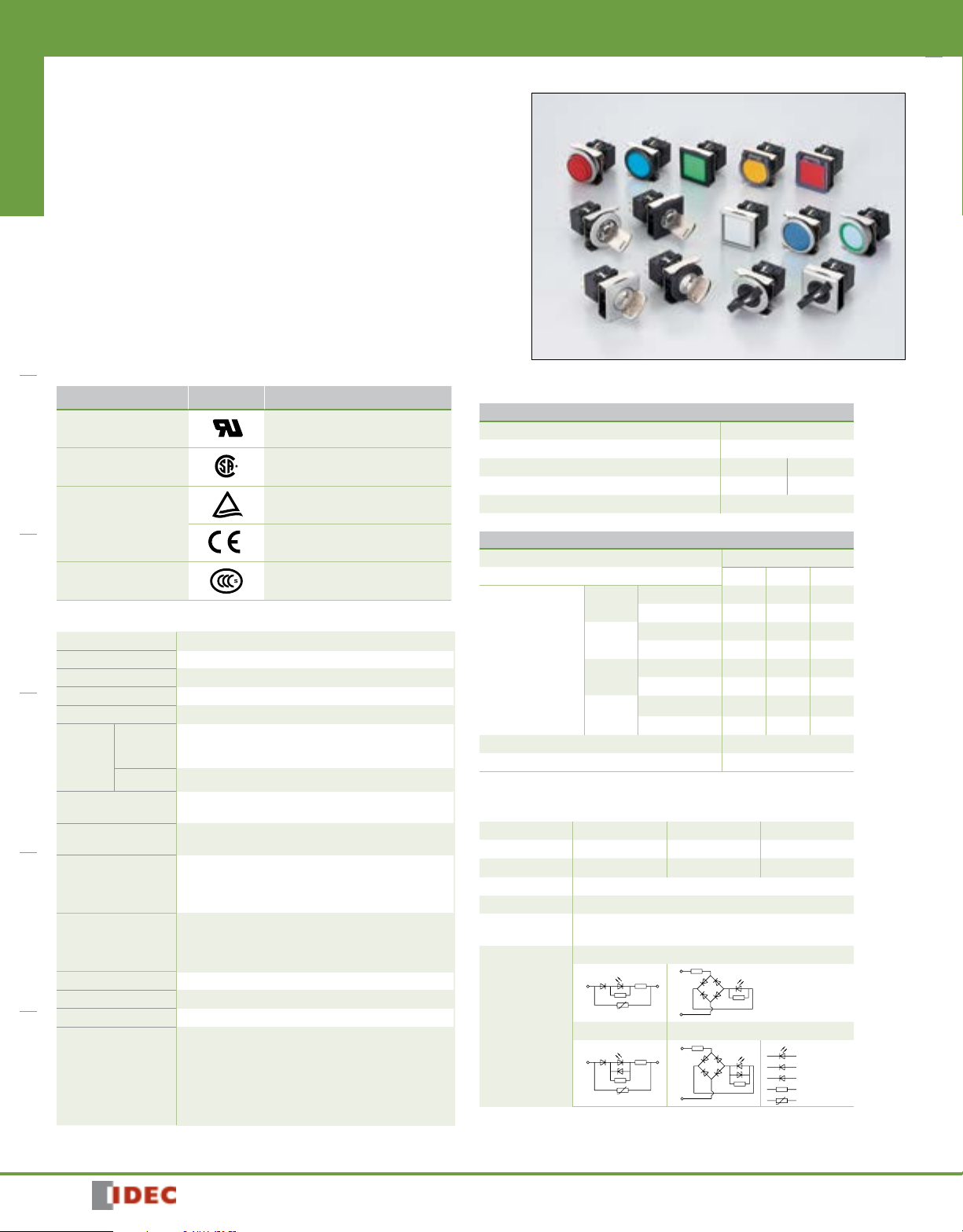
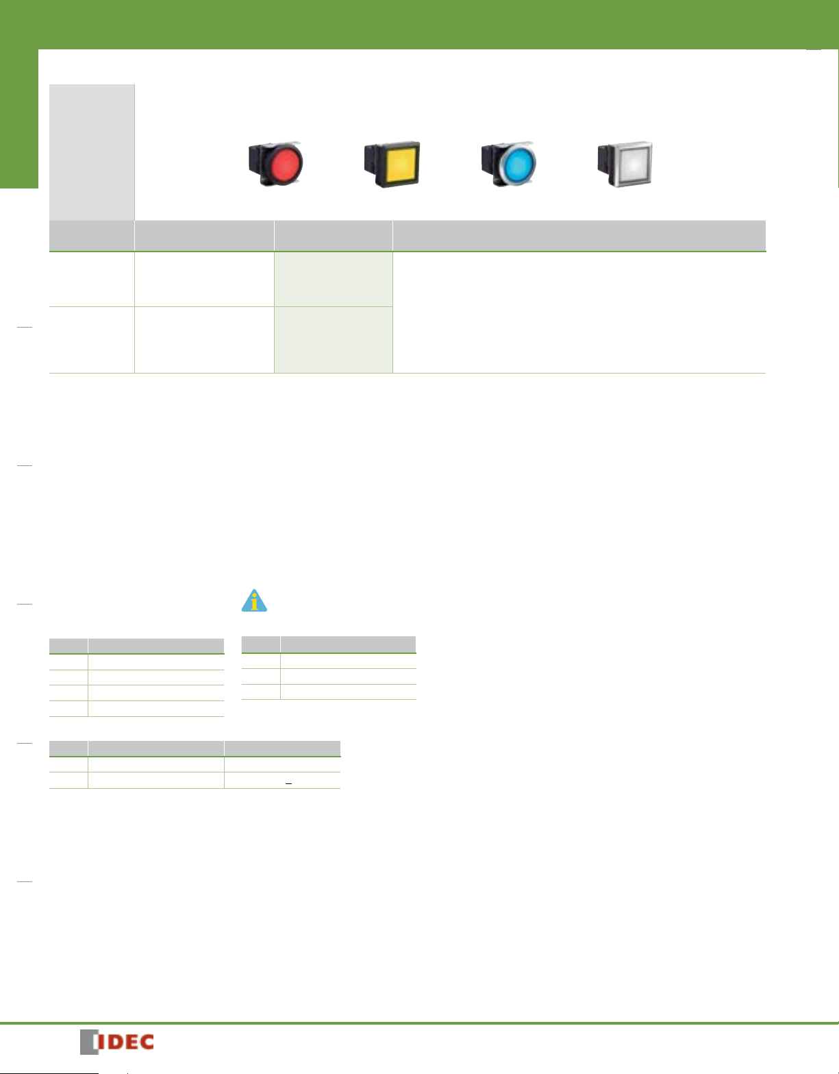
LBW Flush Mount 22mm Switches & Pilot Lights
Flush bezel projects only 2mm from front of panel. Removable contact blocks are
ideal for single board mounting.
Key Features
• Pushbuttons, illuminated pushbuttons, selector switches, and key
Switches & Pilot DevicesSignaling LightsRelays & SocketsTimersContactorsTerminal BlocksCircuit Breakers
selector switches with up to 3PDT contacts.
• Key selectors with keys that are difficult to duplicate. Seven
different key numbers to choose from.
• Pilot lights with round or square flat lenses.
• Solder / Tab or PC Board terminal.
• Black or metallic flush bezels available.
• Guard pushbuttons, illuminated or non-illuminated are available.
• Illuminated pushbuttons with bright, clear, ring, flush or extended lens.
• Choice of either gold-clad or silver contacts.
• Degree of protection: IP65 (from the front of the panel).
Applicable Standards Mark File No. or Organization
UL508
UL Recognition No.E55996
CSA 22.2 No.14 CSA File No. LR 21451
TÜV Rheinland
EN60947-5-1
EU Low Voltage Directive
GB14048.5
Specifications
Operating Temperature –25 to +60°C (no freezing), Illuminated units: –25 to +55°C
Storage Temperature –30 to +80°C (no freezing)
Operating Humidity 45 to 85% RH (no condensation)
Contact Resistance 50 mW maximum (initial value)
Insulation Resistance 100 MW minimum (500V DC megger)
Bet ween live part and ground: 2,000V AC, 1 min.
Dielectric
Strength
Switch
Bet ween terminals of different poles: 2,000V AC, 1 min.
Bet ween terminals of the same poles: 1,000V AC, 1 min.
Illumination Bet ween live part and ground: 2,000V AC, 1 min.
Vibration Resistance
Shock Resistance
Operating extremes/Damage limits:
5 to 55 Hz, amplitude 0.5mm
Operating extremes: 100 m/s
Damage limits: 1,000 m/s
2
2
Momentary: 2,000,000
Mechanical Life
(minimum operations)
Electrical Life
(minimum operations)
Maintained: 250,000
Selector switches: 250,000
Key selector switches: 250,000
Momentary: 50,000 / 100,000
Maintained: 50,000 / 100,000
Selector switches: 50,000 / 100,000
1
2
2
Key selector switches: 50,000 / 100,000
2
Degree of Protection IP65 (IEC 60529)
Terminal Style Solder/tab terminal #110, PC board terminal
Bezel Black plastic or metallic
16g (illuminated puthbutton)
14g (pilot light)
15g (pushbutton)
Weight (approx.)
17g (selector switch)
29g (key switch)
17g (illuminated pushbutton with guard)
18g (push button with guard)
1. Switching frequency 1,800 operations/h.
2. Switching frequency 1,200 operations/h.
578
Contact Ratings
Gold Contact (switch base color: blue)
Rated Insulation Voltage 250V
Rated Thermal Current 3A
Rated Operating Voltage 30V DC 125V AC
Rated Operating Current (resistive load) 0.1A 0.1A
Contact Material Gold-clad silver
Minimum applicable load (reference value): 5V AC/DC, 1 mA
Silver Contact (switch base color: gray)
Rated Insulation Voltage 250V
Rated Operating Voltage 30V 125V 250V
AC
50/60Hz
DC
Rated Operating
Current
AC
50/60Hz
DC
Rated Thermal Current 5A
Contact Material Silver
AC inductive load: PF=0.6 to 0.7 DC inductive load: L/R=7 ms max.
LED Ratings
Rated Voltage 5V DC 12V AC/DC 24V AC/DC
Voltage Range 5V DC±5% 12V AC/DC±10% 24V AC/DC ±10%
LED Part No.
LB9Z-LED5
Rated Current A, R: 22 mA G, PW, S: 16 mA
Voltage Rating Marked on the side of the LED unit
LED Life
(reference value)
Approx. 30,000 hours
(until the brightness reduces to 50% of the initial value)
A, PW, R A, PW, R
X1
(+)
Internal
Circuit
1. For ➁ (color code): A (amber), G (green), PW (white), R (red), S (blue)
2. Use the white LED for yellow illumination.
3. LED lamp contains a current-limiting resistor.
G, S G, S
X1
(+)
Resistive load — 5A 5A
Inductive load — 3A 1.5A
Resistive load 5A 1.1A —
Inductive load 2.5A 0.55A —
Resistive load — 5A 3A
Inductive load — 3A 1.5A
Resistive load 3A 0.6A —
Inductive load 1A 0.22A —
LB9Z-LED1
➁
X2
(–)
X2
(–)
LB9Z-LED2
➁
➁
LED Chip
Protection Diode
Zener Diode
Resistor
1811302120
•
LBW➀L-
➁➂T➃➄➅
∗
Flush
LBW➀L-
∗
Switches & Pilot Devices
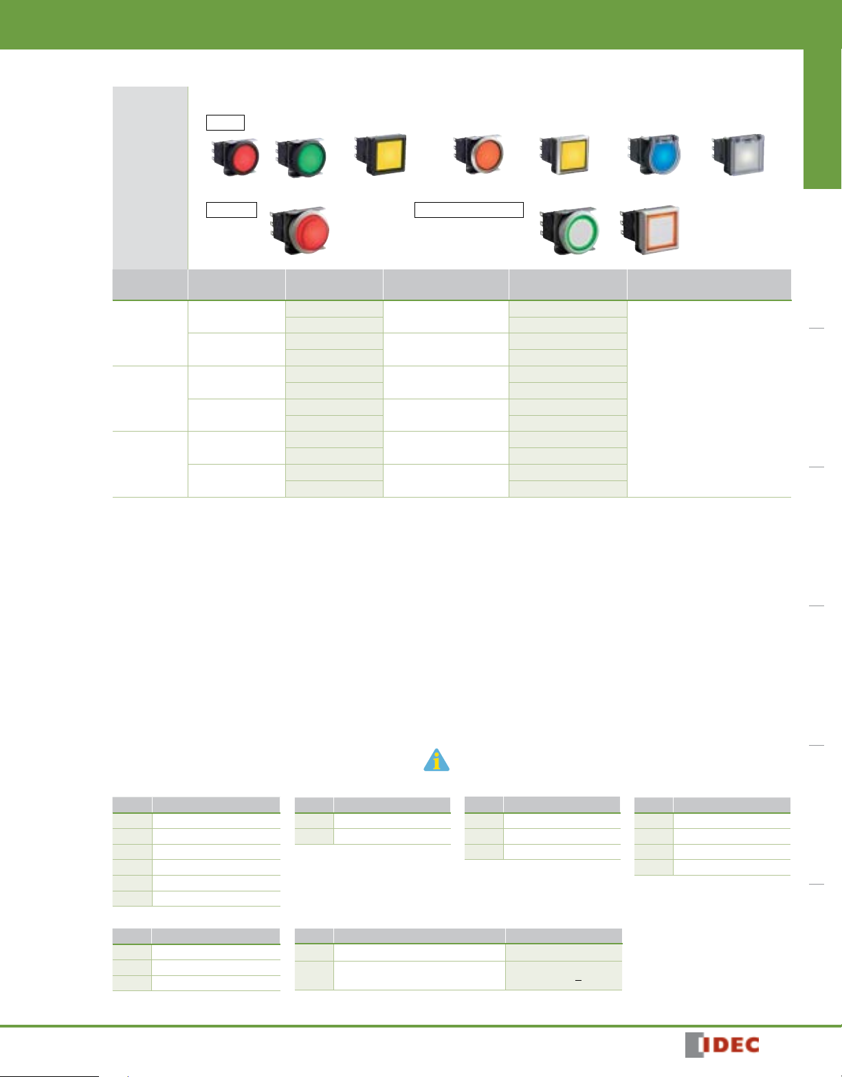
Illuminated Pushbuttons (Assembled)
ø22mm - LBW Series
Switches & Pilot Devices Signaling Lights Relays & Sockets Timers Contactors Terminal Blocks Circuit Breakers
Part No.
Style
➀
Momentary
Black bezel
Maintained
Momentary
Metallic bezel
Maintained
Momentary
Guard Type
Maintained
Flush/Extended color code: A (amber), G (green), PW (pure white), R (red), S (blue), Y (yellow)
•
Ring-illuminated color code: PW (pure white), WA (amber), WG (green), WR (red), WS (blue)
•
Illuminated pushbuttons contain an LED unit. For details on LED units, see 580.
•
The guard opens 180 degrees spring-return.
•
Illuminated pushbuttons can be used with legend markings. Engraving can be done on a marking plate which is placed in the lens, or a clear film can be
•
printed and placed in the lens. See 594 for details on the marking plate and film.
White lens type (when light is off) are available. Clear lens is used instead of colored lens for amber, green, red, and blue illuminated pushbuttons.
•
Amber, green, red, or blue LED units are used. To specify, see Part Number Interpretation below.
PC board terminals available for gold contacts. Silver contacts also available. To specify, see Part Number Interpretation below.
•
Extended style is available. See Part Number Interpretation below (➂).
•
Flush ring-illuminated style is available. See Part Number Interpretation below (➂). Guard is not available with flush ring-illuminated style.
•
5V DC and 12V AC/DC LED operating voltages also available.
•
Marking plates are available. See accessory section.
•
Round / Black Bezel Square / Black
Extended
(black bezel is
also available)
Operation
➁
Contact
➃
Gold/SPDT
Gold/DPDT
Gold/SPDT
Gold/DPDT
Gold/SPDT
Gold/DPDT
Gold/SPDT
Gold/DPDT
Gold/SPDT
Gold/DPDT
Gold/SPDT
Gold/DPDT
Round / Metallic
Bezel
Flush Ring-illuminated
LED Operating Voltage Part No.
➄
24V AC/DC
24V AC/DC
24V AC/DC
24V AC/DC
24V AC/DC
24V AC/DC
Bezel
(black bezel is
also available)
Square / Metallic
Bezel
LBW➀L-M➂T14*
LBW➀L-M➂T24*
LBW➀L-A➂T14*
LBW➀L-A➂T24*
LBW➀L-M➂T14*
LBW➀L-M➂T24*
LBW➀L-A➂T14*
LBW➀L-A➂T24*
LBW➀L-M➂T14*
LBW➀L-M➂T24*
LBW➀L-A➂T14*
LBW➀L-A➂T24*
Round with Guard Square with Guard
* Illumination Color Code
Specify the color code in place
of * in the Part No.
A: amber
G: green
PW: pure white
R: red
S: blue
Y: yellow
1811302120
Part Number Interpretation
➁➂T➃➄➅
Style
➀
Code Shape
6 Round / Black Bezel
7 Square / Black Bezel
6M Round / Metallic Bezel
7M Square / Metallic Bezel
6G Round with Guard
7G Square with Guard
LED Operating Voltage
➄
Code Rated Operating Voltage
1 5V DC
3 12V AC/DC
4 24V AC/DC
To be used for interpreting part numbers only,
not for part number development.
Operator Style
Operation
➁
Code Operation
A Maintained
M Momentary
Others
➅
Code Specification Part No. Example
Blank Solder/Tab Terminal —
PC Board Terminal (Gold Contact
V
Only)
• Specify the color code in place of * in the table above.
➂
Code Operator Style
1 Flush
2 Extended
1R Flush Ring-illuminated
* Extended style is available only for round
(black/metallic bezel) and in momentary operation. Guard model is not
available.
LBW6L-M1T14V*
Contacts
➃
Code Contact
1 Gold/SPDT
2 Gold/DPDT
5 Silver/SPDT
6 Silver/DPDT
579
ø22mm - LBW Series
Switches & Pilot Devices
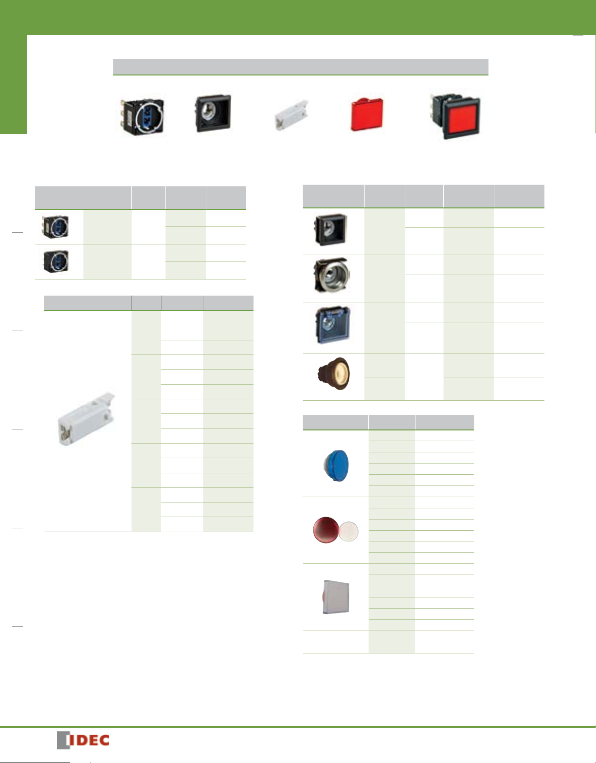
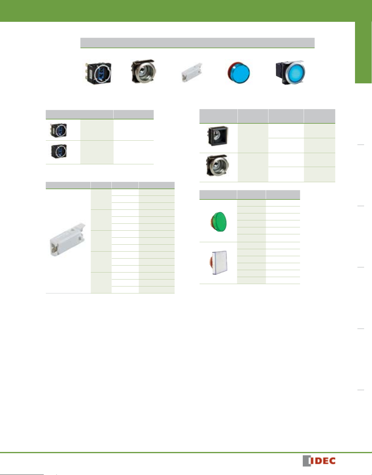
Illuminated Pushbuttons (Sub-assembled)
Contact Block Operator LED Module Lens Completed Unit
Switches & Pilot DevicesSignaling LightsRelays & SocketsTimersContactorsTerminal BlocksCircuit Breakers
+ + +
Contact Block
Terminal Style Material Contact Part
Silver SPDT LB-T50
Solder/Tab
Gold SPDT LB-T10V
PCB
DPDT LB-T60
DPDT LB-T20V
LED Module
Style Color Voltage Part Number
Amber 5V LB9Z-LED5A
12V LB9Z-LED1A
24V LB9Z-LED2A
Green 5V LB9Z-LED5G
12V LB9Z-LED1G
24V LB9Z-LED2G
Red 5V LB9Z-LED5R
12V LB9Z-LED1R
24V LB9Z-LED2R
Blue 5V LB9Z-LED5S
12V LB9Z-LED1S
24V LB9Z-LED2S
Pure
5V LB9Z-LED5PW
White
12V LB9Z-LED1PW
24V LB9Z-LED2PW
Number
=
Operator
Style
Mounting
Style
Flush Mount
(Plastic)
Flush Mount
(Metallic)
Flush Mount
(Built-in
switch
guard)
Flush Mount
(Plastic)
Flush Mount
(Metallic)
Shape Momentary Maintained
Round LBW6L-M0 LBW6L-A0
Square LBW7L-M0 LBW7L-A0
Round LBW6ML-M0 LBW6ML-A0
Square LBW7ML-M0 LBW7ML-A0
Round LBW6GL-M0 LBW6GL-A0
Square LBW7GL-M0 LBW7GL-A0
Round
(for
extended
lens)
LBW6L-M20 LBW6L-A20
LBW6ML-M20 LBW6ML-A20
Lens
Shape Color Part Number
Round (Flush)
Round (Extended)
Square (Flush)
Round Ring Flush White LBW6A-L1R-W
Square Ring Flush White LBW7A-L1R-W
Note: No marking plate used in ring illuminated pushbottons.
Amber LBW6A-L1A
Green LBW6A-L1G
Red LBW6A-L1R
Blue LBW6A-L1S
White LBW6A-L1W
Yellow LBW6A-L1Y
Amber LBW6A-L2A
Green LBW6A-L2G
Red LBW6A-L2R
Blue LBW6A-L2S
White LBW6A-L2W
Yellow LBW6A-L2Y
Amber LBW7A-L1A
Green LBW7A-L1G
Red LBW7A-L1R
Blue LBW7A-L1S
White LBW7A-L1W
Yellow LBW7A-L1Y
580
1811302120
•
Switches & Pilot Devices
Lamp
X2
X1
Lamp
Terminal (+)
Lamp
Terminal (−)
TOP
ø16.
Ring-illuminated
17.8
Panel Thickness:
Panel Thickness:
[PC Board Terminal] [Solder/Tab Terminal] [With Guard] [With Guard]
17.8
Panel Thickness:
[PC Board Terminal] [Solder/Tab Terminal]
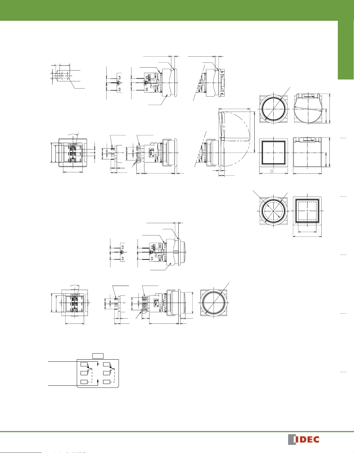
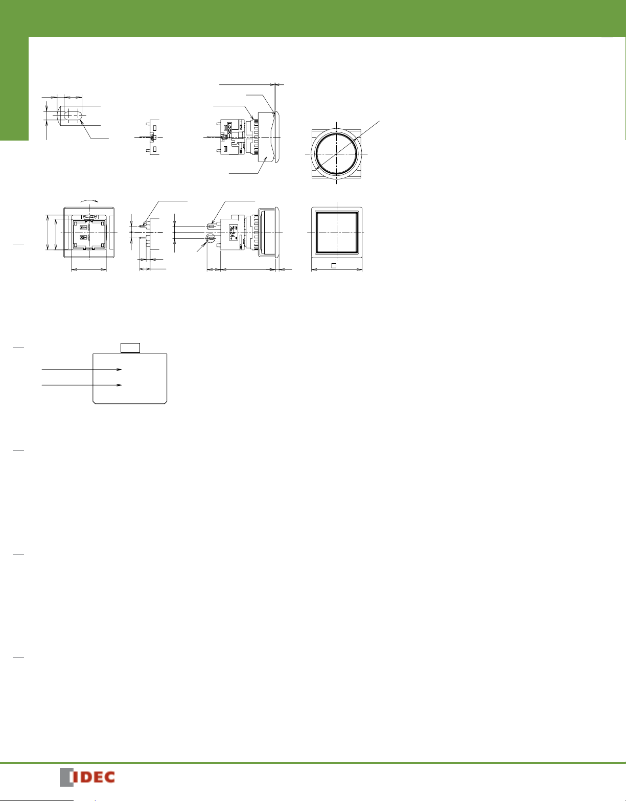
ø22mm - LBW Series
Dimensions All dimensions in mm.
Flush/Ring-illuminated
1 2.6
1.2
∗
Solder/Tab Terminal
LOCK
15.8
17.8
2-R0.6
0.5 to 3.2 mm
Mounting
Bracket
27.9
Gasket
Locking Ring
3.85
6.95
0.8W × 0.5t
1
33
55
3.85
6.95
2.8W × 0.5t
1
6
6
2
∗
5.5
7
0.5 to 3.2 mm
2
Gasket
ø26
Round
ø26
13
SquareSquare
13
26
Round
28.7
37.4
2
5.2
26
Round Square
4
ø26
Switches & Pilot Devices Signaling Lights Relays & Sockets Timers Contactors Terminal Blocks Circuit Breakers
27
27
Extended
3.85
6.95
LOCK
15.8
17.8
0.8W × 0.5t 2.8W × 0.5t
1
55
5.5
Terminal Arrangement (Bottom View)
Terminal (+)
Lamp
Terminal (−)
(SPDT contacts on the right only)
TOP
22
24
21
12
X1
14
X2
11
2
6.95 3.85
1
66
∗
0.5 to 3.2 mm
Locking Ring
Mounting
Bracket
Gasket
16.4
26
Round
ø26
ø20.2
4.67
227.9
1811302120
For details on pc board and circuit design, see 594.
•
For details on single board mounting, see 593.
•
581
ø22mm - LBW Series
LBW➀P-1T0
∗
LBW➀P-1T0
∗
Part No.
Switches & Pilot DevicesSignaling LightsRelays & SocketsTimersContactorsTerminal BlocksCircuit Breakers
Switches & Pilot Devices
Pilot Lights
➁➂
Round / Black Bezel Square / Black Bezel Round / Metallic Bezel Square / Metallic Bezel
Style
➀
Black Bezel 24V AC/DC
Metallic Bezel 24V AC/DC
Pilot lights contain an LED unit. For maintenance LED units see 583.
•
Legends and symbols can be engraved on a marking plate or film to be inserted under the lens by users for labelling purposes. See 596 for details.
•
White lens type (when light is off) are available. Clear lens is used instead of colored lens for amber, green, red, and blue pilot lights. Amber, green, red, or blue
•
LED units are used. To specify, see Part Number Interpretation below.
PC board terminals available. To specify, see Part Number Interpretation below.
•
5V DC and 12V AC/DC LED operating voltages also available.
•
LED Operating Voltage Part No. * Illumination Color Code
➂
LBW➀P-1T04*
LBW➀P-1T04*
Specify the color code in place of * in the Part No.
A: amber
G: green
PW: pure white
R: red
S: blue
Y: yellow
Part Number Interpretation
To be used for interpreting part numbers only,
not for part number development.
LED Operating Voltage
➁
Code Rated Operating Voltage
1 5V DC
3 12V AC/DC
4 24V AC/DC
Style
➀
Code Shape
6 Round / Black Bezel
7 Square / Black Bezel
6M Round / Metallic Bezel
7M Square / Metallic Bezel
➁➂
Others
➂
Code Specification Part No. Example
Blank Solder/Tab Terminal —
V PC Board Terminal
• Specify the color code in place of * in the table above.
582
LBW6P-1T04V*
1811302120
•
Switches & Pilot Devices
ø22mm - LBW Series
Pilot Lights (Sub-assembled)
Contact Block Operator LED Module Lens Completed Unit
+ + +
Contact Block
Terminal Style Part Number
Solder Tab LB-T00
PCB
LED Module
Style Color Voltage Part Number
Amber
Green
Red
Blue
Pure
White
LB-T00V
5V LB9Z-LED5A
12V LB9Z-LED1A
24V LB9Z-LED2A
5V LB9Z-LED5G
12V LB9Z-LED1G
24V LB9Z-LED2G
5V LB9Z-LED5R
12V LB9Z-LED1R
24V LB9Z-LED2R
5V LB9Z-LED5S
12V LB9Z-LED1S
24V LB9Z-LED2S
5V LB9Z-LED5PW
12V LB9Z-LED1PW
24V LB9Z-LED2PW
=
Operator
Style
Mounting
Style
Flush Mount
(Plastic)
Flush Mount
(Metallic)
Shape Part Number
Round LBW6P-0
Square LBW7P-0
Round LBW6MP-0
Square LBW7MP-0
Lens
Shape Color Part Number
Round
Square
Amber LBW6A-P1A
Green LBW6A-P1G
Red LBW6A-P1R
Blue LBW6A-P1S
White LBW6A-P1W
Yellow LBW6A-P1Y
Amber LBW7A-P1A
Green LBW7A-P1G
Red LBW7A-P1R
Blue LBW7A-P1S
White LBW7A-P1W
Yellow LBW7A-P1Y
Switches & Pilot Devices Signaling Lights Relays & Sockets Timers Contactors Terminal Blocks Circuit Breakers
1811302120
583
ø22mm - LBW Series
Panel Thickness:
[PC Board Terminal] [Solder/Tab Terminal]
Switches & Pilot Devices
Dimensions All dimensions in mm.
0.5 to 3.2 mm
Mounting
Bracket
Gasket
Round
ø26
1
Switches & Pilot DevicesSignaling LightsRelays & SocketsTimersContactorsTerminal BlocksCircuit Breakers
1.2
∗ Solder/Tab Terminal
2.6
Locking Ring
2-R0.6
17.8
LOCK
15.8
0.8W × 0.5t
33
2
5.5
Terminal Arrangement (Bottom View)
Lamp
Terminal (+)
Lamp
Terminal (−)
TOP
X1
X2
2.8W × 0.5t
3 3
∗
7 27.9 2 2617.8
Square
584
1811302120
 Loading...