

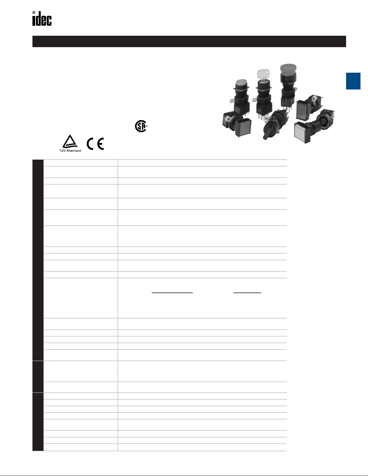
Miniature Switches and Pilot Devices
L6 Series — Miniature Switches and Pilot Devices
Key features of the 5/8” L6 Series include:
• 5/8” (16mm) mounting holes
• Locking lever removable contact blocks
• Solder terminal or PCB terminal options
•Available assembled or as sub-components
•Worldwide approvals
• Incandescent or LED illumination
• Snap action contacts
Registration No. R9551089 (E-stops)
Registration No. J9551458 (all other switches)
Registration No. J9650511 (Pilot Lights)
Conforming to Standards
Operating Temperature
Vibration Resistance
Shock Resistance
Mechanical Life
Degree of Protection
Dielectric Strength
Insulation Resistance
Rated Insulation Voltage
Rated Thermal Current
Contact Ratings
Contact Resistance
Rated Operating Current
Minimum Recommended Load
(reference value for silver contacts)
Terminal Style
Contact Form
Contact Material
Electrical Life
(at full load)
Lamp Current Draw
amp Ratings
Lamp Life
L
Frequency 2 khz ± 500 HZ
Amplitude
Operating Voltage
Adjustable Cycle
Current Draw
Life
Buzzer Ratings
Insulation Voltage
Operating Temperature
EN60947-1, EN60947-5-1, VDE0660-200, UL508, CSA C22-2 N0.14
Operation: –25 to +55°C (without freezing), 45 to 85% rh
Storage: -30 to +80°C (without freezing)
5 to 55Hz, 1.0 peak-peak amplitude max
Operating limit: 100 in/sec
Damage limit: 1000 in/sec
Momentary pushbuttons 2,000,000 operations minimum
All others: 250,000 operations minimum
IP65 (conforming to IEC 60529)
Switch unit: between live and ground: 2500 volt AC, 1 minute
between terminals of different poles: 2500 volt AC, 1 minute
between terminals of same pole: 1000 volt AC, 1 minute
Illumination unit: between live part and ground: 2500 volt AC, 1 minute
100 M Ω minimum (using 500V DC megger)
250 V AC/DC
Gold Contacts (pcb): 3A
Silver Contacts (solder): 5A
50 Ω maximum initial value
Silver Contacts Gold Clad Contacts
(Solder Terminals) (PCB terminals)
30V 125V 250V
AC resistive 3A 3A 2A AC inductive - 0.1A
AC inductive 2A 2A 1.5A DC resistive 0.1A -
DC resistive 2A 0.4A DC inductive 1A 0.2A -
5 VAC/DC, 1mA
0.110” Solder Tab /PCB
Snap Action, Double Throw
Solder Tab: Pure Silver /PCB thermal Gold Plated Silver
Momentary pushbuttons: 100,000 operations minimum (1800 operations / hour)
All others: 100,000 operations minimum (1200 operations / hour)
5V DC LED: 8mA
6V LED: 7mA 6V incandescent: 100 mA
12V LED: 8mA 12V incandescent: 50 mA
24V LED: 8mA 24V incandescent: 25 mA
Incandescent: 2000 hours./LED: 50,000 hours. (on pure DC, half-life intensity)
80db @ 0.1m (at rated voltage)
6V AC/DC or 12 - 24V AC/DC ± 10%
55 to 600 cycles per minute
DC: 7mA
AC: 20mA
1000 hrs. minimum
60V AC/DC
-20 to 55 C (no freezing), 45 to 85% rh
CSA Certified
File No. LR21451
2
(approximately 10G)
2
(approximately 100G)
L6 Series: 16mm
A
Switches & Pilot Devices
30V 125V
www.idec.com
USA: (800) 262-IDEC or (408) 747-0550, Canada (888) 317-IDEC A-35

L6 Series: 16mm
Part Numbers: Non-Illuminated Pushbuttons
Style
Round
A
Square
Rectangular
Switches & Pilot Devices
Operation Contact
Momentary
Maintained
Momentary
Maintained
Momentary
Maintained
Miniature Switches and Pilot Devices
Non-Illuminated Pushbuttons (Assembled)
Button Color Codes
Color Code
Black B
Green G
Red R
Blue S
White W
Yellow Y
SPDT
DPDT
SPDT
DPDT
SPDT
DPDT
SPDT
DPDT
SPDT
DPDT
SPDT
DPDT
Terminal Style
Solder Tab PCB
LA1B-M1C5- ➀
LA1B-M1C6- ➀
LA1B-A1C5- ➀
LA1B-A1C6- ➀
LA2B-M1C5- ➀
LA2B-M1C6- ➀
LA2B-A1C5- ➀
LA2B-A1C6- ➀
LA3B-M1C5- ➀
LA3B-M1C6- ➀
LA3B-A1C5- ➀
LA3B-A1C6- ➀
LA1B-M1C1V- ➀
LA1B-M1C2V- ➀
LA1B-A1C1V- ➀
LA1B-A1C2V- ➀
LA2B-M1C1V- ➀
LA2B-M1C2V- ➀
LA2B-A1C1V- ➀
LA2B-A1C2V- ➀
LA3B-M1C1V- ➀
LA3B-M1C2V- ➀
LA3B-A1C1V- ➀
LA3B-A1C2V- ➀
Oversize Round Flush
Oversize Round
Extended
Oversize Square
Flush
Oversize Square
Extended
Mushroom
Momentary
Maintained
Momentary
Maintained
Momentary
Maintained
Momentary
Maintained
Momentary
SPDT
DPDT
SPDT
DPDT
SPDT
DPDT
SPDT
DPDT
SPDT
DPDT
SPDT
DPDT
SPDT
DPDT
SPDT
DPDT
SPDT
DPDT
HA1B-M1C5- ➀
HA1B-M1C6- ➀
HA1B-A1C5- ➀
HA1B-A1C6- ➀
HA1B-M2C5- ➀
HA1B-M2C6- ➀
HA1B-A2C5- ➀
HA1B-A2C6- ➀
HA2B-M1C5- ➀
HA2B-M1C6- ➀
HA2B-A1C5- ➀
HA2B-A1C6- ➀
HA2B-M2C5- ➀
HA2B-M2C6- ➀
HA2B-A2C5- ➀
HA2B-A2C6- ➀
HA1B-M3C5- ➀
HA1B-M3C6- ➀
HA1B-M1C1V- ➀
HA1B-M1C2V- ➀
HA1B-A1C1V- ➀
HA1B-A1C2V- ➀
HA1B-M2C1V- ➀
HA1B-M2C2V- ➀
HA1B-A2C1V- ➀
HA1B-A2C2V- ➀
HA2B-M1C1V- ➀
HA2B-M1C2V- ➀
HA2B-A1C1V- ➀
HA2B-A1C2V- ➀
HA2B-M2C1V- ➀
HA2B-M2C2V- ➀
HA2B-A2C1V- ➀
HA2B-A2C2V- ➀
HA1B-M3C1V- ➀
HA1B-M3C2V-➀
A-36
Maintained
1. In place of ➀ specify Button Color Code from table on right.
2. Illuminated (translucent) style lenses also available, specify as such: instead of
LA1B-M1C5-➀ use LA1B-M1C5Lnext page.)
3. PCB terminal models also available with silver contacts (change “1” or “2” to
“5” or “6” respectively, ie LA1B-M1C1V-➀ becomes LA1B-M1C5V-➀.
SPDT
DPDT
www.idec.com
HA1B-A3C5-➀
HA1B-A3C6-➀
HA1B-A3C1V-➀
HA1B-A3C2V-➀
➁ in place of ➁ specify Lens Color Code from
USA: (800) 262-IDEC or (408) 747-0550, Canada (888) 317-IDEC

Miniature Switches and Pilot Devices L6 Series: 16mm
① Button Color Code
➁ Lens Color Code
Part Numbers: Contacts
Appearance Contacts
Terminal Style
Solder
Tab
PCB
Gold
SPDT
DPDT
HA-C1
HA-C2
HA-C1V
HA-C2V
Silver
SPDT
DPDT
HA-C5
HA-C6
HA-C5V
HA-C6V
Part Number: Safety Lever Lock
Appearance Part Number
HA9Z-LS
Color Code
Black B
Green G
Red R
Blue S
White W
Yellow Y
Color Code
Amber A
Green G
Red R
Blue S
Yellow Y
White W
Non-Illuminated Pushbuttons (Sub-Assembled)
Contact + Safety Lever Lock + Operator + Button = Complete Part
Part Numbers: Operators
Style Momentary Maintained Style Button Lens
Round
Square
Rectangular
Oversize Round
LA1L-MO LA1L-AO
LA2L-MO LA2L-AO
LA3L-MO LA3L-AO
HA1B-MO HA1B-AO
Part Numbers: Buttons/Lenses
Round
AB6M-BK2-① AL6M-LK2-➁
Square
AB6Q-BK2-① AL6Q-LK2-➁
Rectangular
AB6H-BK2-① AL6H-LK2-➁
Oversize Round Flush
HA1A-B1-① HA1A-L1-➁*
A
Switches & Pilot Devices
Oversize Square
Mushroom
1. In place of ① specify Button Color
Code from table on right.
2. In place of
from table on right.
3. *requires HA1L-M0 or HA1L-A0 operator instead of HA1B-M0 or HA1B-A0.
4. **requires HA2L-M0 or HA2L-A0
instead of HA2B-M0 or HA2B-A0.
www.idec.com USA: (800) 262-IDEC or (408) 747-0550, Canada (888) 317-IDEC A-37
HA2B-MO HA2B-AO
HA1B-MOL HA1B-A0L
➁ specify Lens Color Code
Oversize Round Extended
Oversize Square Flush
Oversize Square
Extended
Mushroom
HA1A-B2-① –
HA2A-B1-① HA2A-L1-➁**
HA2A-B2-① –
HA1A-B3-① HA1A-L3-➁

L6 Series: 16mm Miniature Switches and Pilot Devices
HA1B/HA1E E-Stop
Miniature Switches and Pilot Devices: 5/8"(16mm)
Key features of HA1B/HA1E Push lock Turn Reset include:
• PCB or Solder Terminals
• Quick Release Contact Blocks
A
• Positive Action Contacts
•1 or 2 form B (SPST-NC) Contacts
• IP65 Protection
• 16mm Mounting Hole
•Tamper Proof Construction
File No. DK95-00138
CSA approved
File No. LR21451
UL Recognized
File No. E55996
Direct
Opening
Action
Contact Ratings
Contact Form
Termination
Contact Material
Switches & Pilot Devices
Applicable Standards
Rated Insulation Voltage
Degree of Protection
Conditional Short-Circuit Current
&Short-Circuit Protective Device
Specifications
Positive opening travel 3.4mm
Minimum force required to achieve
Positive
Opening
Operation
positive opening operation of all
break contacts.
Maximum travel including travel
beyond the minimum travel position
Maximum frequency of actuation 1,200 operations/hour
Pollution Degree
Part Numbers: Positive Action E-Stop
Appearance Operation Contact
E-Stop
Pushlock/
Turn Reset
DPST(NC)
(2 form B)
Short
Body
24VDC/2A
120VAC/3A
1 or 2 form B (2-SPST-NC)
PCB or Solder Terminal
Silver
EN 60947-5-1, UL-508, CSA 22.2. No. 14
250V
IP65, when mounted in an enclosure
50 A (at 250V) 10A 250V Fuse, operation class
aM according to IEC269-1 and IEC269-2
10.3 N (2 form B contacts)
5.5mm
3
Terminal Style
Solder Tab PCB
HA1B-V2E2R HA1B-V2E2VR
SPST-NC (1 form B)
DPST-NC (2 form B)
HA1E-V2S1R
HA1E-V2S2R
Part Numbers: Nameplates
HAAV–Yellow Plastic
E
G
N
R
C
E
M
E
Y
Ø 60mm
S
P
T
O
Part Number
Blank HAAV-OY
Engraved
Emergency Stop
–
HAAV-27
Button is nonremovable, available in red and as
complete assembled
unit only.
Conditional short circuit and protective device 10A 250V fuse operating class acc. to IEC 269-1 and IEC 269-2
min travel: 3.4 mm
Positive opening operation
Pollution Degree 3
Part Number: Buzzers
Appearance Operating Voltage
Buzzer-Rectangular
min force: 10.3N
max travel: 5.5mm
max. frequency: 1200 ops/hr.
Terminal Style
Solder/Tab PCB
6V AC/DC ± 10% LA3Z-1X2 LA3Z-1X2V
12V to 24 AC/DC ± 10% LA3Z-1X4 LA3Z-1X4V
Frequency: 2khz ± 500 hz
Amplitude: 80db at 0.1m
Beeping: Adjustable from steady
tone to 600 beeps per minute.
A-38 www.idec.com USA: (800) 262-IDEC or (408) 747-0550, Canada (888) 317-IDEC

Miniature Switches and Pilot Devices L6 Series: 16mm
Part Numbers: Pilot Lights (LED)
Style Voltage
Round
24V AC/DC LED
24VAC/DC Incandescent
Square
Pilot Lights (Assembled)
Terminal Style
Solder Tab PCB
LA1P-1C04-➁
LA1P-1C07-➁
LA1P-1C04V-➁
LA1P-1C07V-➁
➁
Lens/LED Color Codes
Color Code
Amber A
Green G
Red R
Blue S
Yellow Y
White W
A
Switches & Pilot Devices
Rectangle
Oversize Round
Oversize Square
24V AC/DC LED
24V AC/DC Incandescent
24V AC/DC LED
24V AC/DC Incandescent
24V AC/DC LED
24V AC/DC Incandescent
24V AC/DC LED
24V AC/DC Incandescent
LA2P-1C04LA2P-1C07- ➁
LA3P-1C04LA3P-1C07-➁
HA1P-1C04HA1P-1C07-➁
HA2P-1C04HA2P-1C07-➁
➁
➁
LA2P-1C04V-➁
LAZP-1C07V-➁
LA3P-1C04V-➁
LA3P-1C07V-➁
➁
➁
HA1P-1C04V-➁
HA1P-1C07V-➁
HA2P-1C04V-➁
HA2P-1C07V-➁
Voltage/Lamp Code
Voltage Code
5V DC LED 1
6V AC/DC LED 2
12V AC/DC LED 3
24V AC/DC LED 4
120 V AC LED 8
6V AC/DC Incandescent 5
12V AC/DC Incandescent 6
24V AC/DC Incandescent 7
Oversize Round Monolithic
➁
➁
–
–
Oversize Square Monolithic
24V AC/DC LED
24V AC/DC Incandescent
24V AC/DC LED
24V AC/DC Incandescent
HA1P-14HA1P-17-➁
HA2P-14HA2P-17-➁
1. In place of ➁ specify Lens/LED Color Code from table.
2. Lamps also available in 5VDC, 6V AC/DC, 12V AC/DC or 120V AC, change “4” or
“7” using Voltage/Lamp Codes (ie LA1P-1C03-
➁ uses 12V AC/DC LED).
www.idec.com USA: (800) 262-IDEC or (408) 747-0550, Canada (888) 317-IDEC A-39

L6 Series: 16mm Miniature Switches and Pilot Devices
Pilot Lights (Sub-Assembled)
Terminals +
Safety Lever Lock +
Lamp Holder + Lamp + Operator + Lens = Completed Unit
A
Part Numbers: Operators Part Numbers: Lenses
Style Part Number Style Part Number
Round
LA1P-0
Square
Switches & Pilot Devices
Rectangular
Oversize Round
LA2P-0
LA3P-0
HA1P-0
Round
Square
Rectangular
Oversize Round
AL6M-LK3-
AL6Q-LK3-
AL6H-LK3-
HA1A-P1-
➁
➁
➁
➁
Part Numbers: Lamps
Style Voltage
LED
Incandescent
5V DC
6V AC/DC
12V AC/DC
24V AC/DC
120 V AC
6V AC/DC
12V AC/DC
24V AC/DC
In place of ➁ specify LED color
code from table below.
Part Numbers: Terminals
Appearance
Solder
Tab
HA-C00 HA-C00V
Part
Number
LFTD-5
LFTD-6➁
LFTD-1➁
LFTD-2➁
LFTD-H2
LH-06
LH-14
LH-28
PCB
➁
➁
Oversize Square
Oversize Round Monolithic
Oversize Square Monolithic
HA2P-0
HA1P-00
HA2P-00
Oversize Square
HA2A-P1-
In place of ➁ specify lens color
code.
e
Part Number
Not required for monolithic
models
➁
Part Number: Lamp Holder
Appearance Part Number
S
HA9Z-AH
t
y
Part Number: Safety Lever Lock
l
Appearance Part Number
HA9Z- LS
➁ Lens/LED Color Codes
Color Code
Amber A
Green G
Red R
Blue S
Yellow Y
A-40 www.idec.com USA: (800) 262-IDEC or (408) 747-0550, Canada (888) 317-IDEC

Miniature Switches and Pilot Devices L6 Series: 16mm
➁
Lens Color Codes
Voltage/Lamp Code
Color Code
Amber A
Green G
Red R
Blue S
Yellow Y
White W
Voltage Code
5V DC LED 1
6V AC/DC LED 2
12V AC/DC LED 3
24V AC/DC LED 4
120V AC LED 8
6V AC/DC Incandescent 5
12V AC/DC Incandescent 6
24V AC/DC Incandescent 7
Illuminated Pushbuttons (Assembled)
Part Numbers: Illuminated Pushbuttons
Style Operation Lamp Voltage Contact
Round
Square
Rectangular
Oversize Round
Oversize Square
Mushroom
1. In place of➁ specify lens color code from table at right.
2. Lamps also available in 5V DC, 6V AC/DC, 12 V AC/DC or 120V AC, change “4”
or “7” using voltage/lamp codes (ie LA1P-1C03-
3. PCB terminal models also available with silver contacts (change “1” or “2” to
“5” or “6” respectively, ie LA1L-M1C14V-➀ becomes LA1L-M1C54V-➀.
Momentary
Maintained
Momentary
Maintained
Momentary
Maintained
Momentary
Maintained
Momentary
Maintained
Momentary
Maintained
24V AC/DC LED
24V AC/DC
Incandescent
24V AC/DC LED
24V AC/DC
Incandescent
24V AC/DC LED
24V AC/DC
Incandescent
24V AC/DC LED
24V AC/DC
Incandescent
24V AC/DC LED
24V AC/DC
Incandescent
24V AC/DC LED
24V AC/DC
Incandescent
24V AC/DC LED
24V AC/DC
Incandescent
24V AC/DC LED
24V AC/DC
Incandescent
24V AC/DC LED
24V AC/DC
Incandescent
24V AC/DC LED
24V AC/DC
Incandescent
24V AC/DC LED
24V AC/DC
Incandescent
24V AC/DC LED
24V AC/DC
Incandescent
Terminal Style
Solder Tab PCB
SPDT
DPDT
SPDT
DPDT
SPDT
DPDT
SPDT
DPDT
SPDT
DPDT
SPDT
DPDT
SPDT
DPDT
SPDT
DPDT
SPDT
DPDT
SPDT
DPDT
SPDT
DPDT
SPDT
DPDT
SPDT
DPDT
SPDT
DPDT
SPDT
DPDT
SPDT
DPDT
SPDT
DPDT
SPDT
DPDT
SPDT
DPDT
SPDT
DPDT
SPDT
DPDT
SPDT
DPDT
SPDT
DPDT
SPDT
DPDT
LA1L-M1C54LA1L-M1C64-➁
LA1L-M1C57LA1L-M1C67-➁
LA1L-A1C54LA1L-A1C64-➁
LA1L-A1C57LA1L-A1C67-➁
LA2L-M1C54LA2L-M1C64-➁
LA2L-M1C57LA2L-M1C67-➁
LA2L-A1C54LA2L-A1C64-➁
LA2L-A1C57LA2L-A1C67-➁
LA3L-M1C54LA3L-M1C64-➁
LA3L-M1C57LA3L-M1C67-➁
LA3L-A1C54LA3L-A1C64-➁
LA3L-A1C57LA3L-A1C67-➁
HA1L-M1C54HA1L-M1C64-➁
HA1L-M1C57HA1L-M1C67-➁
HA1L-A1C54HA1L-A1C64-➁
HA1L-A1C57HA1L-A1C67-➁
HA2L-M1C54HA2L-M1C64-➁
HA2L-M1C57HA2L-M1C67-➁
HA2L-A1C54HA2L-A1C64-➁
HA2L-A1C57HA2L-A1C67-➁
HA1L-M3C54HA1L-M3C64-➁
HA1L-M3C57HA1L-M3C67-➁
HA1L-A3C54HA1L-A3C64-➁
HA1L-A3C57HA1L-A3C67-➁
➁ uses 12V AC/DC LED).
➁
➁
➁
➁
➁
➁
➁
➁
➁
➁
➁
➁
➁
➁
➁
➁
➁
➁
➁
➁
➁
➁
➁
➁
LA1L-M1C14V-➁
LA1L-M1C24V-➁
LA1L-M1C17V-➁
LA1L-M1C27V-➁
LA1L-A1C14V-➁
LA1L-A1C24V-➁
LA1L-A1C17V-➁
LA1L-A1C27V-➁
LA2L-M1C14V-➁
LA2L-M1C24V-➁
LA2L-M1C17V-➁
LA2L-M1C27V-➁
LA2L-A1C14V-➁
LA2L-A1C24V-➁
LA2L-A1C17V-➁
LA2L-A1C27V-➁
LA3L-M1C14V-➁
LA3L-M1C24V-➁
LA3L-M1C17V-➁
LA3L-M1C27V-➁
LA3L-A1C14V-➁
LA3L-A1C24V-➁
LA3L-A1C17V-➁
LA3L-A1C27V-➁
HA1L-M1C14V-➁
HA1L-M1C24V-➁
HA1L-M1C17V-➁
HA1L-M1C27V-➁
HA1L-A1C14V-➁
HA1L-A1C24V-➁
HA1L-A1C17V-➁
HA1L-A1C27V-➁
HA2L-M1C14V-➁
HA2L-M1C24V-➁
HA2L-M1C17V-➁
HA2L-M1C27V-➁
HA2L-A1C14V-➁
HA2L-A1C24V-➁
HA2L-A1C17V-➁
HA2L-A1C27V-➁
HA1L-M3C14V-➁
HA1L-M3C24V-➁
HA1L-M3C17V-➁
HA1L-M3C27V-➁
HA1L-A3C14V-➁
HA1L-A3C24V-➁
HA1L-A3C17V-➁
HA1L-A3C27V-➁
A
Switches & Pilot Devices
www.idec.com USA: (800) 262-IDEC or (408) 747-0550, Canada (888) 317-IDEC A-41

L6 Series: 16mm Miniature Switches and Pilot Devices
Illuminated Pushbuttons (Sub-Assembled)
Contacts +
Safety Lever Lock +
Lamp Holder + Lamp + Operator + Lens = Completed Unit
A
Part Numbers: Operators Part Numbers: Lenses
Style Momentary Maintained Style Part Number
Round
LA1L-MO LA1L-AO
Switches & Pilot Devices
Square
LA2L-MO LA2L-AO
Rectangula
r
LA3L-MO LA3L-AO
Round
Square
Rectangular
AL6M-LK2-➁
AL6Q-LK2-➁
AL6H-LK2-➁
Part Numbers: Lamps
Appearance Voltage Part Number
5V DC
6V AC/DC
12V AC/DC
24V AC/DC
120V AC
6V AC/DC
12V AC/DC
24V AC/DC
LED
Incandescent
In place of ➁ specify LED color code
from table below.
Part Numbers: Contacts
Appearance Contacts
➁
LFTD-5
LFTD-6➁
LFTD-1➁
LFTD-2➁
LFTD-H2➁
LH-06
LH-14
LH-28
Terminal Style
Solder
Tab
PCB
Oversize Round
Oversize Square
Mushroom
HA1L-MO HA1L-A0
HA2L-MO HA2L-AO
HA1B-MOL HA1B-AOL
Oversize
Round
HA1A-L1-
Oversize
Square
HA2A-L1-
Mushroom
HA1A-L3-
In place of ➁ specify
Lens Color Code from
table.
SPDT
Gold
DPDT
➁
Part Number:Lamp Holder
➁
➁
Appearance Part Number
Part Number: Safety Lever Lock
Appearance Part Number
Silver
HA9Z-AH
HA9Z-LS
SPDT
DPDT
➁ Lens/LED Color Codes
Color Code
Amber A
Green G
Red R
Blue S
Yellow Y
White W
HA-C10
HA-C20
HA-C50
HA-C60
HA-C10V
HA-C20V
HA-C50V
HA-C60V
A-42 www.idec.com USA: (800) 262-IDEC or (408) 747-0550, Canada (888) 317-IDEC

Miniature Switches and Pilot Devices L6 Series: 16mm
As viewed from front of
switch.
Selector Switches (Assembled)
Part Numbers: Selector Switches
Style Position
Maintained
Round
Square
Spring return from right
90˚ 2 -Position
Maintained
Spring return from right
Spring return from left
2-Way spring return
45˚ 3-Position
Maintained
Spring return from right
90˚ 2-Position
Maintained
Spring return from right
Spring return from left
Contact Operations
Contact
L
R
DPDT LA1S-2C6 LA1S-2C2V
L
R
DPDT LA1S-21C6 LA1S-21C2V
C
L
L
L
L
L
L
L
L
L
DPDT LA1S-3C6 LA1S-3C2V
R
C
DPDT LA1S-31C6 LA1S-31C2V
R
C
DPDT LA1S-32C2VLA1S-32C6
R
C
DPDT LA1S-33C6 LA1S-33C2V
R
R
DPDT LA2S-2C6 LA2S-2C2V
R
DPDT LA2S-21C6 LA2S-21C2V
C
DPDT LA2S-3C6 LA2S-3C2V
R
C
DPDT LA2S-31C6 LA2S-31C2V
R
C
DPDT LA2S-32C6 LA2S-32C2V
R
Terminal Style
Solder Tab PCB
(for all selectors)
Contacts
2-pos.
(DPDT)
3-pos.
(DPDT)
Operator Position and
Contact Operation
Left
Right
Left
Center
Right
Left Right
Left
NO NC
Left
NO NC
Left Right
Left
NO NC
NO NCNO NC
NO NC
Right
NO NC
NO NCNO NC
NO NC
A
Switches & Pilot Devices
Right
Right
Rectangular
Oversize Round
2-Way spring Return
45˚ 3-Position
Maintained
Spring return from right
90˚ 2-Position
Maintained
Spring return from right
Spring return from left
2-Way spring Return
45˚ 3-Position
Maintained
Spring return from right
90˚ 2-Position
Maintained
Spring return from right
Spring return from left
2-Way spring Return
45˚ 3-Position
C
L
L
L
L
L
L
L
L
L
L
L
L
L
DPDT LA2S-33C6 LA2S-33C2V
R
R
DPDT LA3S-2C6 LA3S-2C2V
R
DPDT LA3S-21C6 LA3S-21C2V
C
DPDT LA3S-3C6 LA3S-3C2V
R
C
DPDT LA3S-31C6 LA3S-31C2V
R
C
DPDT LA3S-32C6 LA3S-32C2V
R
C
DPDT LA3S-33C6 LA3S-33C2V
R
R
DPDT HA1S-2C6 HA1S-2C2V
R
DPDT HA1S-21C6 HA1S-21C2V
C
DPDT HA1S-3C6 HA1S-3C2V
R
C
DPDT HA1S-31C6 HA1S-31C2V
R
C
DPDT HA1S-32C6 HA1S-32C2V
R
C
DPDT HA1S-33C6 HA1S-33C2V
R
1. All assembled selector switches use
DPDT contacts.
2. For SPDT contacts see sub-components on next page.
3. PCB terminal models also available
with silver contacts (change “1” or
“2” to “5” or “6” respectively, ie
LA1S-21C2V becomes LA1S-21C6V.
www.idec.com USA: (800) 262-IDEC or (408) 747-0550, Canada (888) 317-IDEC A-43

L6 Series: 16mm Miniature Switches and Pilot Devices
Selector Switches (Sub-Assembled)
Contacts + Safety Lever Lock + Operator = Complete Part
A
Part Numbers: Operators
Style Position Function Part Number
Round
2
Maintained
Spring from right
LA1S-2Y
LA1S-21Y
Maintained
3
Square
2
Switches & Pilot Devices
3
Rectangular
Oversize Round
Part Numbers: Contacts
2
3
2
3
Spring from right
Spring from left
Spring from both
Maintained
Spring from right
Maintained
Spring from right
Spring from left
Spring from both
Maintained
Spring from right
Maintained
Spring from right
Spring from left
Spring from both
Maintained
Spring from right
Maintained
Spring from right
Spring from left
Spring from both
Appearance Contacts
Gold
SPDT
DPDT
LA1S-3Y
LA1S-31Y
LA1S-32Y
LA1S-33Y
LA2S-2Y
LA2S-21Y
LA2S-3Y
LA2S-31Y
LA2S-32Y
LA2S-33Y
LA3S-2Y
LA3S-21Y
LA3S-3Y
LA3S-31Y
LA3S-32Y
LA3S-33Y
HA1S-2Y
HA1S-21Y
HA1S-3Y
HA1S-31Y
HA1S-32Y
HA1S-33Y
Terminal Style
Solder Tab PCB
HA-C1
HA-C2
HA-C1V
HA-C2V
SPDT
DPDT
Silver
1. All assembled switches listed on previous page use DPDT contacts.
2. SPDT Contacts for use on 2 position selector switch only
Part Number: Safety Lever Lock
HA-C5
HA-C6
HA-C5V
HA-C6V
Appearance Part Number
HA9Z-LS
A-44 www.idec.com USA: (800) 262-IDEC or (408) 747-0550, Canada (888) 317-IDEC

Miniature Switches and Pilot Devices L6 Series: 16mm
As viewed from front of
switch.
Key Switches (Assembled)
Part Numbers: Key Switches
Style
Round
Square
Rectangular
Operation Contacts
Maintained
Spring
return from
90 2-Position
right
Maintained
Spring
return from
right
Spring
return from
left
2-Way
spring
45 ˚3-Position
return
Maintained
Spring
return from
90˚ 2-Position
right
Maintained
Spring
return from
right
Spring
return from
left
2-Way
spring
return
45 ˚3-Position
Maintained
Spring
return from
90 ˚2-Position
right
Maintained
Contact Operations
Terminal Type
Solder Tab PCB
L
R
DPDT
L
R
DPDT LA1K-21C6B LA1K-21C2VB
C
L
R
DPDT
C
L
R
DPDT
C
L
R
DPDT
C
L
R
DPDT LA1K-33C6D LA1K-33C2VD
L
R
DPDT
L
R
DPDT LA2K-21C6B LA2K-21C2VB
C
L
R
DPDT
C
L
R
DPDT
C
L
R
DPDT
C
L
R
DPDT LA2K-33C6D LA2K-33C2VD
L
R
DPDT
L
R
DPDT LA3K-21C6B LA3K-21C2VB
C
L
R
DPDT
LA1K-2C6
LA1K-3C6
LA1K-31C6
LA1K-32C6➂ LA1K-32C2V➂
LA2K-2C6
LA2K-3C6
LA2K-31C6
LA2K-32C6
LA3K-2C6
LA3K-3C6
➂ LA1K-2C2V➂
➂ LA1K-3C2V➂
➂ LA1K-31C2V➂
➂ LA2K-2C2V➂
➂ LA2K-3C2V➂
➂ LA2K-31C2V➂
➂ LA2K-32C2V➂
➂ LA3K-2C2V➂
➂ LA3K-3C2V➂
(for all selectors)
Contacts
2-pos.
(DPDT)
3-pos.
(DPDT)
Operator Position and
Contact Operation
Left
Right
Left
Center
Right
Left Right
Left
NO NC
Left
NO NC
Left Right
Left
NO NC
NO NCNO NC
Right
NO NC
Right
NO NC
NO NCNO NC
Right
NO NC
➂ Key Retention Option Codes
Code Description
Key not retained in any position
A
(removable in all positions)
B Key retained in right position only
C Key retained in left position only
Key retained in left and right
D
(3 position only)
Key retained in center only
E
(3 position only)
Key retained right and center
G
(3 position only)
Key retained left and center
H
(3 position only)
A
Switches & Pilot Devices
C
L
R
DPDT
C
L
R
DPDT
C
L
R
DPDT LA3K-33C6D LA3K-33C2VD
L
R
DPDT
L
R
DPDT HA1K-21C6B HA1K-21C2VB
C
L
R
DPDT
LA3K-31C6
LA3K-32C6
HA1K-2C6
HA1K-3C6
➂ LA3K-31C2V➂
➂ LA3K-32C2V➂
➂ HA1K-2C2V➂
➂ HA1K-3C2V➂
1. In place of ➂ specify Ke y Retention
Code from next page.
2. All assembled key switches have
DPDT contacts. For SPDT see sub-
Oversize Round
Spring
return from
right
Spring
return from
left
2-Way
spring
45 ˚3-Position
return
Maintained
Spring
return from
90 ˚2-Position
right
Maintained
assembled on next page.
Spring
return from
right
Spring
return from
left
2-Way
spring
45 ˚3-Position
return
www.idec.com USA: (800) 262-IDEC or (408) 747-0550, Canada (888) 317-IDEC A-45
C
L
R
DPDT
C
L
R
DPDT
C
L
R
DPDT HA1K-33C6D HA1K-33C2VD
HA1K-31C6
HA1K-32C6
➂ HA1K-31C2V➂
➂ HA1K-32C2V➂
3. PCB terminal models also available with silver contacts (change
“1” or “2” to “5” or “6” respectively, ie LA1K-2C2V➂ becomes
LA1K-2C6V➂.

L6 Series: 16mm Miniature Switches and Pilot Devices
Key Switches (Sub-Assembled)
Contacts + Safety lever lock + Operator = Complete Part
A
Part Numbers: Operators
Style Positions Operation Part Number
Round
2
3
Switches & Pilot Devices
Square
Rectangular
Oversize Round
2
3
2
3
2
3
Maintained
Spring from right
Maintained
Spring from right
Spring from left
Spring from both
Maintained
Spring from right
Maintained
Spring from right
Spring from left
Spring from both
Maintained
Spring from right
Maintained
Spring from right
Spring from left
Spring from both
Maintained
Spring from right
Maintained
Spring from right
Spring from left
Spring from both
LA1K-2➂
LA1K-21B
LA1K-3
LA1K-31➂
LA1K-32➂
LA1K-33D
LA2K-2➂
LA2K-21B
LA2K-3➂
LA2K-31➂
LA2K-32➂
LA2K-33D
LA3K-2
LA3K-21B
LA3K-3
LA3K-31➂
LA3K-32➂
LA3K-33D
HA1K-2
HA1K-21B
HA1K-3
HA1K-31➂
HA1K-32➂
HA1K-33D
Part Numbers: Contacts
Terminal Style
Appearance Contacts
SPDT
➂
1. All assembled selectors listed on previous
page use DPDT contacts.
2. SPDT contacts are for use on 2 position key
switches only.
Part Number: Safety Lever Lock
Gold
Silver
DPDT
SPDT
DPDT
Solder
Tab
HA-C1
HA-C2
HA-C5
HA-C6
PCB
HA-C1V
HA-C2V
HA-C5V
HA-C6V
Appearance Part Number
➂
HA9Z-LS
➂
➂ Key Retention Option Codes
Code Description
➂
➂
Key not retained in any position
A
(removable in all positions)
B Key retained in right position only
C Key retained in left position only
D Key retained in left and right (3 position only)
E Key retained in center only (3 position only)
G Key retained right and center (3 position only)
H Key retained left and center (3 position only)
1. In place of ➂ specify key r emovable code fr om table
on right.
2. Operator includes two keys.
A-46 www.idec.com USA: (800) 262-IDEC or (408) 747-0550, Canada (888) 317-IDEC

Miniature Switches and Pilot Devices L6 Series: 16mm
NO NCNO NC
Left Right
Illuminated Selector Switches
Part Numbers: Illuminated Selectors Switches
Style Operation Contact Voltage
24V LED
24V Incand.
24V LED
24V Incand.
24V LED
24V Incand.
24V LED
24V Incand.
24V LED
24V Incand.
24V LED
24V Incand.
24V LED
24V Incand.
24V LED
24V Incand.
24V LED
24V Incand.
24V LED
24V Incand.
24V LED
24V Incand.
24V LED
24V Incand.
24V LED
24V Incand.
24V LED
24V Incand.
24V LED
24V Incand.
24V LED
24V Incand.
24V LED
24V Incand.
24V LED
24V Incand.
24V LED
24V Incand.
24V LED
24V Incand.
24V LED
24V Incand.
24V LED
24V Incand.
24V LED
24V Incand.
24V LED
24V Incand.
Round
Square
Rectangular
Oversize Round
Maintained
Spring
return from
90˚ 2-Position
right
Maintained
Spring
return from
right
Spring
return from
left
2-Way
spring
45˚ 3-Position
return
Maintained
Spring
return from
90˚ 2-Position
right
Maintained
Spring
return from
right
Spring
return from
left
2-Way
spring
45˚ 3-Position
return
Maintained
Spring
return from
90˚ 2-Position
right
Maintained
Spring
return from
right
Spring
return from
left
2-Way
spring
45˚ 3-Position
return
Maintained
Spring
return from
90˚ 2-Position
right
Maintained
Spring
return from
right
Spring
return from
left
2-Way
spring
45˚ 3-Position
return
L
R
DPDT
L
R
DPDT
C
L
L
L
L
L
L
L
L
L
L
L
L
L
L
L
L
L
L
L
L
L
L
DPDT
R
C
DPDT
R
C
DPDT
R
C
DPDT
R
R
DPDT
R
DPDT
C
DPDT
R
C
DPDT
R
C
DPDT
R
C
DPDT
R
R
DPDT
R
DPDT
C
DPDT
R
C
DPDT
R
C
DPDT
R
C
DPDT
R
R
DPDT
R
DPDT
C
DPDT
R
C
DPDT
R
C
DPDT
R
C
DPDT
R
Terminal Style
Solder Tab PCB
LA1F-2C64-➁
LA1F-2C67-➁
LA1F-21C64-➁
LA1F-21C67-➁
LA1F-3C64-➁
LA1F-3C67-➁
LA1F-31C64-➁
LA1F-31C67-➁
LA1F-32C64-➁
LA1F-32C67-➁
LA1F-33C64-➁
LA1F-33C67-➁
LA2F-2C64-➁
LA2F-2C67-➁
LA2F-21C64-➁
LA2F-21C67-➁
LA2F-3C64-➁
LA2F-3C67-➁
LA2F-31C64-➁
LA2F-31C67-➁
LA2F-32C64-➁
LA2F-32C67-➁
LA2F-33C64-➁
LA2F-33C67-➁
LA3F-2C64-➁
LA3F-2C67-➁
LA3F-21C64-➁
LA3F-21C67-➁
LA3F-3C64-➁
LA3F-3C67-➁
LA3F-31C64-➁
LA3F-31C67-➁
LA3F-32C64-➁
LA3F-32C67-➁
LA3F-33C64-➁
LA3F-33C67-➁
HA1F-2C64-➁
HA1F-2C67-➁
HA1F-21C64-➁
HA1F-21C67-➁
HA1F-3C64-➁
HA1F-3C67-➁
HA1F-31C64-➁
HA1F-31C67-➁
HA1F-32C64-➁
HA1F-32C67-➁
HA1F-33C64-➁
HA1F-33C67-➁
LA1F-2C24V-➁
LA1F-2C27V- ➁
LA1F-21C24V-➁
LA1F-21C27V-➁
LA1F-3C24V-➁
LA1F-3C27V-➁
LA1F-31C24V-➁
LA1F-31C27V-➁
LA1F-32C24V-➁
LA1F-32C27V-➁
LA1F-33C24V-➁
LA1F-33C27V-➁
LA2F-2C24V-➁
LA2F-2C27V-➁
LA2F-21C24V-➁
LA2F-21C27V-➁
LA2F-3C24V-➁
LA2F-3C27V-➁
LA2F-31C24V-➁
LA2F-31C27V-➁
LA2F-32C24V-➁
LA2F-32C27V-➁
LA2F-33C24V-➁
LA2F-33C27V-➁
LA3F-2C24V-➁
LA3F-2C27V-➁
LA3F-21C24V-➁
LA3F-21C27V-➁
LA3F-3C24V-➁
LA3F-3C27V-➁
LA3F-31C24V-➁
LA3F-31C27V-➁
LA3F-32C24V-➁
LA3F-32C27V-➁
LA3F-33C24V-➁
LA3F-33C27V-➁
HA1F-2C24V-➁
HA1F-2C27V-➁
HA1F-21C24V-➁
HA1F-21C27V-➁
HA1F-3C24V-➁
HA1F-3C27V-➁
HA1F-31C24V-➁
HA1F-31C27V-➁
HA1F-32C24V-➁
HA1F-32C27V-➁
HA1F-33C24V-➁
HA1F-33C27V-➁
Contact Operations
(for all selectors)
Contacts
2-pos.
(DPDT)
3-pos.
(DPDT)
Operator Position and
Contact Operation
Left
Right
Left
Center
Right
Left Right
Left
NO NC
Left
NO NC
Left
NO NC
NO NCNO NC
Right
NO NC
Right
NO NC
Right
NO NC
As viewed from front of
switch.
➁ Lens/LED Color Code
Color Code
Amber A
Green G
Red R
Blue S
Yellow Y
White W
Voltage/Lamp Code
Voltage Code
5V DC LED 1
6V AC/DC LED 2
12V AC/DC LED 3
24V AC/DC LED 4
120V AC LED 8
6V AC/DC Incandescent 5
12V AC/DC Incandescent 6
24V AC/DC Incandescent 7
1. In place of ➁ specify Lens/LED Color
Code from table above.
2. Lamps also available in 5V DC, 6V
AC/DC or 12 V AC/DC, change “4”
or “7” using voltage/lamp codes (ie
LA1F-2C63-➁ uses 12V AC/DC
LED).
3. All switches listed have DPDT contacts. For SPDT see sub-assembled
on next page.
4. PCB terminal models also avail-
able with silver contacts (change
“1” or “2” to “5” or “6” respectively, ie LA1F-2C24V
becomes LA1F-2C64V-
-➁
➁.
A
Switches & Pilot Devices
www.idec.com USA: (800) 262-IDEC or (408) 747-0550, Canada (888) 317-IDEC A-47

L6 Series: 16mm Miniature Switches and Pilot Devices
Illuminated Selector Switches (Sub-Assembled)
Contacts + Safety lever lock + Lamp Holder + Lamp + Operator + Lens/Handle = Completed Unit
A
Part Numbers: Operators
Style Positions Function Part Number
Round
Square
2
3
2
Switches & Pilot Devices
3
Rectangular
Oversize Round
Part Numbers: Contacts
2
3
2
3
Maintained
Spring from right
Maintained
Spring from right
Spring from left
Spring from both
Maintained
Spring from right
Maintained
Spring from right
Spring from left
Spring from both
Maintained
Spring from right
Maintained
Spring from right
Spring from left
Spring from both
Maintained
Spring from right
Maintained
Spring from right
Spring from left
Spring from both
LA1F-20
LA1F-210
LA1F-30
LA1F-310
LA1F-320
LA1F-330
LA2F-20
LA2F-210
LA2F-30
LA2F-310
LA2F-320
LA2F-330
LA3F-20
LA3F-210
LA3F-30
LA3F-310
LA3F-320
LA3F-330
HA1F-20
HA1F-210
HA1F-30
HA1F-310
HA1F-320
HA1F-330
Terminal Style
Appearance
Contacts
SPDT
Gold
DPDT
Solder
Tab
HA-C1
HA-C2
PCB
HA-C10V
HA-C20V
Part Numbers: Lenses/Handles
Appearance Part Number
Standard
LA1A-F-
➁
Oversize
➁
HA1A-F-
In place of ➁ specify Lens Color Code
from table.
Part Number: Safety Lever Lock
Appearance Part Number
HA9Z-LS
Part Number: Lamp Holder
Appearance Part Number
HA9Z-AH
Silver
SPDT
DPDT
HA-C50
HA-C60
HA-C50V
HA-C60V
Part Numbers: Lamps
Appearance Voltage Part Numbers
1. All assembled selectors on previous pa ges use DPDT con-
tacts. SPDT contacts are for use only on two position
selectors.
➁ LED/Lens Color Code
Color Code
Amber A
Green G
Red R
Blue S
Yellow Y
White W
LED
Incandescent
In place of ➁ specify LED Color Code
from table.
5V DC
6V AC/DC
12V AC/DC
24V AC/DC
120V AC
6V AC/DC
12V AC/DC
24V AC/DC
➁
LFTD-5
LFTD-6➁
LFTD-1➁
LFTD-2➁
LFTD-H2➁
LH-06
LH-14
LH-28
A-48 www.idec.com USA: (800) 262-IDEC or (408) 747-0550, Canada (888) 317-IDEC

Miniature Switches and Pilot Devices L6 Series: 16mm
① Button Color Code
Color Code
Black B
Green G
Red R
Blue S
Yellow Y
N
Part Numbers: Pushbutton Selectors
Style
Pushbutton Selectors (Assembled)
Terminal Style
Solder Tab PCB
Contact Operation
Style
2 Position
3 Position
Part Numbers: Lever Switches
Style
Contact Operation
Contacts
2-pos.
(DPDT)
2-pos
(DPDT).
3-pos.
(DPDT)
www.idec.com USA: (800) 262-IDEC or (408) 747-0550, Canada (888) 317-IDEC A-49
2 Position
3 Position
HA1R-2C6-① HA1R-2C2V-①
HA1R-3C6-① HA1R-3C2V-①
1. In place of ① specify Button Color Code.
2. PCB terminal models also available with silver contacts (change “1” or “2” to
“5” or “6” respectively, ie HA1R-2C2V
-① becomes HA1R-2C6V-①.
Operator Position
Left Center Right
Normal Depressed Normal Depressed Normal Depressed
Left
Left Right
NO NCNO NC
Left Right
NO NCNO NC
NO NC
Left
NO NC
Right
NO NC
Right
NO NC
––
Left Right
NO NCNO NC
Blocked
Lever Switch (Assembled)
Terminal Type
Solder Tab PCB
LA1T-31C6
LA1T-32C6
LA1T-31C2V
LA1T-32C2VDPDT
Maintained
Spring from Up
Spring Return
from Down
All models
Operation Contacts
U
Maintained
D
U
Spring return from top
2-Position
Spring Return from bottom
Maintained
Spring return from top
3-Position
Spring return from bottom
Spring return from both
Operator Position & Contact Operation
Down Center Up
Left Right
NO NCNO NC
Left
Right
NO NC
NO NC
Right
Left
NO NC
NO NC
Left Right
ONC
NO NC
Left
NO NC
Left Right
Left
NO NC
D
U
U
C
D
C
D
U
C
D
U
C
D
NO NC
NO NCNO NC
D
U
Right
Right
NO NC
DPDT LA1T-2C6 LA1T-2C2V
DPDT LA1T-21C6 LA1T-21C2V
DPDT LA1T-22C6 LAIT-22C2V
DPDT LA1T-3C6 LA1T-3C2V
DPDT
DPDT LA1T-33C6 LA1T-33C2V
As viewed from front of
switch.
Right
Left Right
NO NCNO NC
Left Right
NO NCNO NC
Left
NO NC
NO NC
Left
NO NC
PCB terminal models also available
with silver contacts (change “1” or
“2” to “5” or “6” respectively, ie
LA1T-2C2V becomes LA1T-2C6V.
A
Switches & Pilot Devices
Right
NO NC

L6 Series: 16mm Miniature Switches and Pilot Devices
Accessories
Part Specifications Part Number Notes
Used for tightening the plastic locking ring when
Ring Wrench Made of metal MT-001
A
Lamp Holder Tool
(Made of Rubber)
Made of rubber. Used for removing and
replacing LED and incandescent lamps in
illuminated units.
OR-44
installing the L6 series unit on a panel.
Tightening torque should not exceed 9kgf cm when
tightening a locking ring.
Rubber tool used for replacing LED and
incandescent lamps.
Lens Removal Tool For Illuminated pushbuttons and pilot lights. MT-101
5V DC
LED Lamp
Incandescent Lamp
Switches & Pilot Devices
Switch Guard
Dust-proof Cover
Terminal Cover
Mounting Hole Plug
Replacement Keys
6V AC/DC
12V AC/DC
24V AC/DC
120V AC
6V AC/DC
12V AC/DC
24V AC/DC
90 degrees opening maintained
180 degrees
opening, spring
return
For round units AL-D6
For square units AL-DQ6
For rectangular units AL-DH6
Made of white
nylon
Rubber AL-B6
Aluminum AL-BM6
for LA1K (#132)
for HA1K (#231) KG9Z-SK-231PN02
Round/Square AL-K6
Rectangular AL-KH6
Round/Square AL-K6SP
Rectangular AL-KH6SP
Oversize Round/Sq HA9Z-K1
Oversize Round/Sq HA9Z-KW1
All removable
contacts
Monolithic Pilot Lights H6-PVL
LFTD-5➁
LFTD-6➁
LFTD-1➁
LFTD-2➁
LFTD-H2➁
LH-06
LH-14
LH-28
H6-VL2
AS6-SK-132PN02
Used for removing the lens or button
from the housing.
T 1-3/4 miniature flange base. In place of ➁ specify LED
Color Code (see page A-48).
0.5W, T 1-3/4 miniature flange base
Prevents inadvertent switch operation. IP40 dust-tight
rated.
Prevents inadvertent switch operation. IP65 oiltight
rated.
Provides extra level of sealing for “front-panel” portion
of switches. (Not applicable for units with oversize
lenses or buttons).
Covers terminals to prevent possible electric shock.
Fills unused panel cutouts. Made of nitrile rubber.
Push-in installation from front of panel. IP65 (oiltight)
rated.
Fills unused panel cutouts. Made of aluminum. Screwon locking ring from inside of panel. IP65 (oiltight) rated.
Pair of keys.
Replacement
Engraving Inserts
Replacement
Locking Ring
Replacement
Anti-Rotation Ring
Replacement
Selector Inserts
Replacement
Safety Lever Lock
Round
Square
Rectangle
Oversize Round
Oversize Square
Mushroom
All models HA9Z-LN
L6 standard AL6-LP
L6 oversize HA9Z-LP
AL6M-W
AL6Q-W
AL6H-W
HA9Z-P1-W
HA9Z-P2-W
HA9Z-P13-W
HA9Z-HC1-①
HA9Z-LS
Prevents rotation of switches in panel.
(included with all assembled switches)
Applicable to round oversize selectors only
① = (G, R, S, W, Y)
A-50 www.idec.com USA: (800) 262-IDEC or (408) 747-0550, Canada (888) 317-IDEC

Miniature Switches and Pilot Devices L6 Series: 16mm
0.71
(18.0)
0.27
(6.8)
0.35
(9.0)
1.39
(35.4)
0.38
(9.6)
0.71
(18.0)
0.71
(18.0)
0.94
(24.0)
0.71
(18.0)
0.98
(24.8)
0.24
(6.0)
0.11
(2.8)
0.71
(18.0)
0.27
(6.8)
0.35
(9.0)
1.39
(35.4)
0.38
(9.6)
0.71
(18.0)
0.71
(18.0)
0.94
(24.0)
0.71
(18.0)
0.98
(24.8)
0.11
(2.8)
0.24
(6.0)
Non -Illuminated Pushbuttons (LA*B)
Emergency Stop Switch (HA1B)
NC
NC
ø0.70"
(17.8mm)
LOCK
+
-
ø0.83"
(21mm)
RO.61"
(15.5mm)
0.62"
(15.8mm)
0.34"
(8.7mm)
0.21"
(5.4mm)
PCB Terminal
0.20"
(5.2mm)
Dimensions
Rubber Washer
Stopper
Locking Ring
0.41"
(10.5mm)
1.42" (36mm)
0.53"
(13.5mm)
Panel Thickness
0.02"-0.24" (0.5~6.0mm)
0.43"
(11mm)
0.98" (25mm)
Ø 0.98"
(24.9mm)
A
Switches & Pilot Devices
Emergency Stop Switch (HA1E)
Buzzer (LA3Z)
0.24
(6.0)
0.62
(15.7)
Pilot Lights (LA*P)
0.35
(9.0)
0.11
(2.8)
1.39
(35.4)
0.35
(9.0)
0.94
(24.0)
0.71
(18.0)
0.98
(24.8)
www.idec.com USA: (800) 262-IDEC or (408) 747-0550, Canada (888) 317-IDEC A-51

L6 Series: 16mm Miniature Switches and Pilot Devices
Dimensions con’t
Illuminated Pushbuttons (LA*L)
0.11
A
0.71
(18.0)
(2.8)
0.24
(6.0)
0.71
(18.0)
0.98
(24.8)
0.27
(6.8)
0.35
(9.0)
Key Switches (LA*K)
0.11
(2.8)
0.24
(6.0)
0.71
(18.0)
Switches & Pilot Devices
0.27
(6.8)
0.35
(9.0)
Selector Switches (LA*S)
0.11
(2.8)
0.24
(6.0)
0.71
(18.0)
0.27
(6.8)
Panel Cut-Out
0.35
(9.0)
PCB Layout (except for Buzzer and E-Stop)
1.39
(35.4)
1.39
(35.4)
1.39
(35.4)
(24.9)
0.66
(16.8)
0.38
(9.6)
.98
0.71
(18.0)
0.71
(18.0)
0.71
(18.0)
0.71
(18.0)
0.71
(18.0)
0.71
(18.0)
0.94
(24.0)
0.94
(24.0)
0.94
(24.0)
0.71
(18.0)
0.71
(18.0)
0.98
(24.8)
0.98
(24.8)
PCB Pins
0.20
(5.0)
0.20
(5.0)
0.27
(6.8)
0.25
(6.4)
Acess Hole
for Locking Lever
Ø0.05
(1.2)
0.36
(9.3)
0.06
(1.5)
0.04
(1.0)
0.24
(6.0)
0.42
(10.7)
0.20
(5.0)
0.03
(0.8)
0.94
(24.0)
HA1B E-Stop
PCB Mounting Pattern
0.21"
(5.3mm)
fl 0.05"
(1.2mm)
0.21"
(5.3mm)
(5.4mm)
0.21"
0.34"
(8.7mm)
A-52 www.idec.com USA: (800) 262-IDEC or (408) 747-0550, Canada (888) 317-IDEC

Miniature Switches and Pilot Devices L6 Series: 16mm
]
]
]
]
]
]
]
]
]
Oversize Flush Pushbutton and Pilot Lights
Dimensions con’t
Oversize Extended Non-Illuminated Pushbutton
Oversize Monolithic PIlot Lights
0.43 [11.0
0.59 [15.1
.02 [25.9
0.94 [24.0
A
Switches & Pilot Devices
Mushroom Pushbuttons
Oversize Selector Switch
1.48 [37.5
0.79 [20.0
0.77 [19.5
1.18 [30.0]
1.18 [30.0
0.94 [23.8]
0.94 [23.8
www.idec.com USA: (800) 262-IDEC or (408) 747-0550, Canada (888) 317-IDEC A-53

L6 Series: 16mm Miniature Switches and Pilot Devices
]
]
Dimensions con’t
Oversize Key Switch
A
1.54 [39.0
Lever Switch
Switches & Pilot Devices
Terminal Configurations
Non Illuminated Pushbutton
Lamp Terminal
(+)
NOCNC
NOCNC
Lamp Terminal
(–)
.94
.51
(24.)
(13)
.93
(23.5)
.41
(10.5)
.98
(25)
AL-D6
ø24
.94"
1.79
(45.5)
Pilot Lights
X2X2 X1
AL-KH6SP
1.30
(33)
1.34
(34)
R22
Illuminated Pushbuttons
Lamp Terminal
(+)
Lamp Terminal
(–)
Panel Thickness:
.20 max. (5 max)
X2X2 X1
AL-DQ6
1.18
(30)
0.94 [23.8
NOCNC
NOCNC
Input
Terminal
(X2)
.51
(13)
.93
(23.5)
.41
(10.5)
AL-K6SP
.71
(18)
.75
(19)
AL-DH6
.94
(24)
Buzzer
X2X2
Steady Slow Quick
(45.5)
1.79
Input
Terminal
X1 X1
(X1)
Buzzer
Sound
Switch
.94
(24)
.51
.30
(13)
.01
(0.3)
(7.5)
Water-proof Gasket
.51
(13)
.01
(0.3)
.30
(7.5)
Water-proof Gasket
.01
(0.3)
(13)
.51
Water-proof Gasket
.30
(7.5)
A-54 www.idec.com USA: (800) 262-IDEC or (408) 747-0550, Canada (888) 317-IDEC

Miniature Switches and Pilot Devices L6 Series: 16mm
Dimensions con’t
LED Lamp
1.85
(47)
.59
(15)
H6-VL2
TOP Marking Side
.16
(4)
.83
(21)
.69
(17.6)
AL-B6
.08
(2)
(18)
.70
.65
(16.5)
Internal Circuit
AL-BM6
.24
(6)
.10
(2.5)
Gasket
.70
(17.8)
.47
(12)
Locking Ring
A
Switches & Pilot Devices
LED Chip
Protective Diode
Zener Diode
www.idec.com USA: (800) 262-IDEC or (408) 747-0550, Canada (888) 317-IDEC A-55

L6 Series: 16mm Miniature Switches and Pilot Devices
General Instructions
Pushbutton Assembly
Lamp Installation
Lamps can be replaced in two ways:
A
1. If contacts are accessible (or pushbutton not installed in a panel) then
it is easiest to first remove the contacts from the operator. This will allow
easy access to the lamp/lamp-holder assembly. Grab lamp, depress
slightly, and turn counter clockwise. Lamp can then be removed by
pushing it back through the lamp holder.
2. If contacts are not accessible, then the lamp can be replaced by first
removing the lens from the operator. Just pull lens straight out either
with a fingernail or optional lens removal tool (MT-101). Lamp/lampholder assembly can then be removed with lamp removal tool (OR-44).
Insert lamp removal tool through operator, depress slightly, turn counter
clockwise, then pull lamp/lamp-holder assembly out. Lamp can then be
removed by pushing it back through the lamp holder.
Engraving Lenses
All buttons and lenses can be engraved directly on the outside surface.
Switches & Pilot Devices
Illuminated lenses also allow for engraving on a plate that is underneath
the colored section of the lens. Remove the colored section of the lens
by pulling on the edge while simultaneously unhooking it from the
latches on the lens holder. The marking plate will then be accessible. It
can then be engraved or a thin marked insert (such as mylar or paper)
can be sandwiched between the marking plate and colored section of
the lens.
Recess
Latches
Engraving
Area
Color Lens Marking Plate Lens Holder
Panel Mounting
Before any unit can be mounted into a panel, the contact block must be removed. Slide metal locking lever and pull contact off. Loosen and
remove the locking ring and square anti-rotation ring from the operator and insert operator through panel cutout from the front of the panel.
Slide on anti-rotation ring and tighten locking ring, using locking ring wrench (MT-001). Slide contact block onto operator, observing TOP
marking on both parts. Slide metal locking lever in direction indicated by LOCK. The yellow plastic safety lever lock can then be snapped onto
the locking lever; this will prevent vibration or maintenance actions from releasing the contact from the operator.
PCB Mounting
Being able to separate the contacts from the operator allows for assembly of the front panel components (operator and lens) to be performed in
tandem with the PC board assembly and soldering. For applications
where multiple rows of pushbuttons are mounted closely together, or
where other components may obstruct access to the contact locking
lever, be sure to include access holes in the PC board (refer to PC board
layout dimensions for location). Also be sure to allow for space above
and to the side of contact to ensure that no components block the contact block locking lever. PC board pins are designed to rest on the PCB,
take this into consideration to ensure that pins do not short closely
spaced traces.
A-56 www.idec.com USA: (800) 262-IDEC or (408) 747-0550, Canada (888) 317-IDEC

Switches and Pilot Devices General Information
General Information
Information About LED Lamps
Light-emitting diodes (LEDs) are P–N junction semiconductors with mechanisms called “junction electro-luminescence.” Application of direct current results in radiation or emission of a monochromatic light.
Different semiconductor materials produce different wavelengths of light as shown below:
Green Gallium Phosphide (GaP) 5600 Å
Yellow
Amber
Red
Specifications
Infrared Gallium Arsenide (GaAs) 9000 Å
Advantages of Using LEDs
• LEDs are used when heat generated by incandescent lamps would damage nearby equipment or interfere with
a precision process. This is particularly advantageous when multiple lights are grouped.
• LEDs can operate at low temperatures which would cause incandescent lamps to fail, since glass cracks during rapid cooling.
• LEDs consume 50 times less power than incandescent lamps, thereby reducing energy consumption.
• LEDs last 500 times longer than incandescent lamps. LEDs average a million hours (114 years) while incandescent lamps average 2000 hours.
• LEDs do not generally “blow out” unless subjected to a severe overvoltage. They exhibit a half-life type
dimishment in brightness over time. After 50,000 hours (6 years) of use, IDEC LEDs will retain approximately
half of their original intensity.
• IDEC’s SUPERBRIGHT LEDs have high visibility.
• LEDs require little or no maintenance because of long life and high reliability.
Gallium Arsenide
Phosphide (GaAsP)
Gallium Arsenide
Phosphide (GaAsP)
Gallium Arsenide
Phosphide (GaAsP)
5800 Å
6300 Å
6600Å
A
Switches & Pilot Devices
IDEC Recommendations
For optimum results, especially when using switches and pilot lights in operating environments which are conducive to overheating, use IDEC LED illuminated units. Transformers are available for use with incandescent illuminated units, which operate
at lower voltages to avoid overheating.
When IDEC’s L-120L lamp is used, make sure ambient temperatures do not exceed 30˚C (86˚F). If
a lamp from another supplier is used, it should be rated f or less than 1.8 watts (15mA at 120V A C),
with ambient temperatures as stated above.
Information About Incandescent Lamps
Filament-type incandescent lamps operate within the following parameters.
Light output and life expectancy depend on operating voltage. Light output varies to the 3rd or 4th power of the voltage. Life
expectancy varies inversely to the 12th power of voltage. In other words, over-voltage of 5% reduces life expectancy by 50%.
Under-voltage of 5% doubles life expectancy at the price of light output efficiency.
Inrush current (initial current through the filament) has an adverse effect on life expectancy. Cold resistance (room temperature)
will have a more detrimental effect than hot resistance to inrush current. Life expectancy of incandescent lamps can be maximized by reducing occurrences of cold resistance to inrush current.
Continued intermittent flashing will significantly reduce life expectancy. When using an incandescent lamp with a tungsten filament, flashing will not reduce life expectancy as long as light output does not exceed that of steady burning.
When an incandescent lamp must withstand shock and vibration, use low voltage/high amperage (5–6V/60–120mA) lamps.
These lamps have a short, thick filament with a high resonant frequency.
Provide cooling by using a heat sink, particularly when multiple incandescent lamps are grouped or when air circulation is limited. Make sure ambient temperatures do not exceed 100˚C (212˚F) for maximum life of incandescent lamps.
www.idec.com USA: (800) 262-IDEC or (408) 747-0550, Canada (888) 317-IDEC A-11

General Information Switches and Pilot Devices
Comparison: LED vs. Incandescent Lamps
Superbright LEDs Incandescent
A
Heat Dissipation
Life Expectancy
Reliability
Mechanical
Strength
Maintenance
Required
Operation at Low
Temps.
Characteristics
Inrush Current
Voltage Effects
on Life
Brightness
Very Low High
Very Long Short
Very High Low
Not Susceptible Susceptible to Shock/Vibration
Negligible Frequent
Possible Not Possible
Negligible Very Large
Insignificant Significant
Slightly Less Slightly More
Switches & Pilot Devices
1. IDEC offers assembled and sub-assembled switches and pilot lights for your convenience. In some cases there is a cost difference, with sub-assembled units
costing slightly less. Since assembled units are custom made to your order, a couple of days for assembly is added to delivery. To minimize delivery or inventory
requirements, it is recommended that switches and pilot lights be ordered as sub-components.
2. When ordering pilot lights or illuminated pushbuttons, make sure to specify the color code in place of the asterisk in the part number, (LED or incandescent lamp
included). Spare lamps can be ordered and are listed with sub-assembly components.
3. Accessories, such as locking ring wrench, lens removal tool, and lamp holder, are available to make installation and assembly easier. IDEC recommends using
these accessories and is not responsible for damage as a result of using the wrong tool.
4. Marking plates are available for switches and pilot lights which feature a flat lens. Printed mylar (not included) can also be inserted under lens for labeling purposes.
5. Nameplates are available for TW, 7/8" (22mm), HW 7/8" (22mm),and TWTD series, Ø1–13/64" (30mm). For prompt delivery, order standard legends. Custom
engraving is also offered for an additional charge.
1. Use the appropriate lamp holder to remove or install LED or incandescent lamps. Using pliers will damage the lamp.
2. When mounting switches and pilot lights into a panel, use locking ring wrench.Using pliers or tightening excessively will damage the locking ring.
3. A series, 21/64" (8mm), can be mounted on a panel 0.019" (0.5mm) to 0.236" (6mm) thick.
4. LW 7/8” (22mm), TW, 7/8" (22mm), and TWTD series, Ø1–13/64" (30mm), feature an adjustment ring for mounting on a panel 0.038" (1mm) to 0.236" (6mm)
thick. Using a nameplate or an anti-rotation ring adds 0.031" (0.8mm) to the panel thickness.
5. When applicable, solder terminals within 20W/5sec or 260˚/3sec without exerting external force to the terminals. Use a non-corrosive resin liquid flux.
6. The operating voltage for LED units represents a complete DC value. When using a pulsing voltage, such a full-wave rectification, keeppeak currents within the
forward current I
7. To avoid a short circuit, never connect NO and NC contacts to different voltages or power sources.
8. Optimum performance of TW and TWTD illuminated pushbuttons, selector switches, and pilot lights is obtained with IDEC LED and incandescent lamps.
9. For maximum life of incandescent lamps (approximately 2000 hours), use within the rated operating voltage. If it is necessary to use a higher voltage, keeping
ambient temperature below 30˚C (86˚F)will help prolong the life of an incandescent lamp.
. Peak currents exceeding If may shorten the life of the LED lamp.
f
Ordering Information
Installation and Operation
If excessive voltage is applied (over 50V), the lamp may blow and
the lens holder may pop out.
A-12 www.idec.com USA: (800) 262-IDEC or (408) 747-0550, Canada (888) 317-IDEC
 Loading...