

Page 1

ø22mm
YW Series Switches & Pilot Lights
Page 2
Innovative Design, Space-Saving, Safety,
and Self-Cleaning Contacts
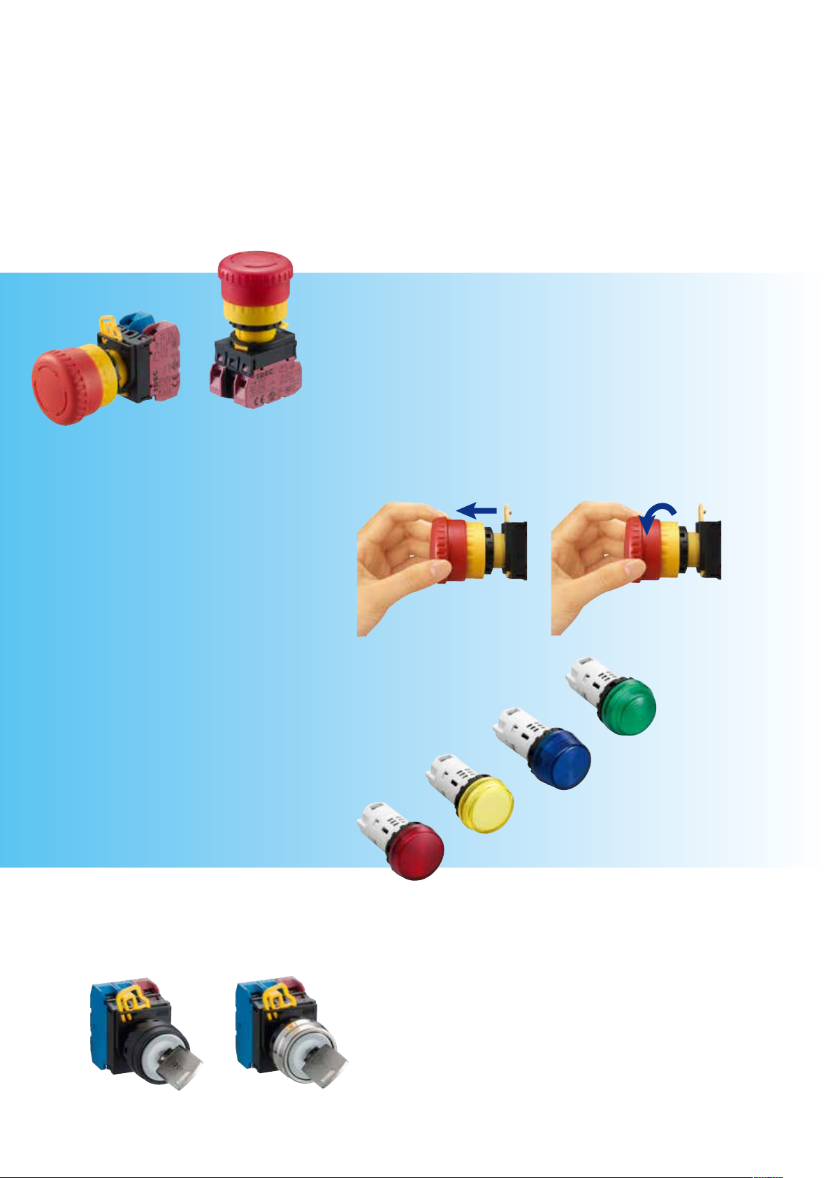
Emergency Stop Switches
Satisfy International Standards
• Safety Lock Mechanism
When the emergency stop signal has been generated during actuation of the emergency stop
device, the emergency stop function shall be maintained until the emergency stop device is
reset (disengaged)
(IEC 60947-5-5, 6.2).
• Direct Opening Action
Even if the contacts are welded, NC contacts are forced to open and break the circuit
(compliant to IEC 60947-5-1, Annex K, IEC 60947-5-5, 5.2).
Non-illuminated Illuminated
• Safe Pushbutton Design
The pushbutton is designed to ensure that an object cannot become trapped between the
mushroom button and the panel, disabling the button operation. In addition, the pushbutton is
designed to prevent removal from the front of the panel (IEC 60947-5-5, 6.3.2).
Easy Operation
• Push-to-lock, Pull/Turn-to-release
YW emergency stop switches can be unlatched by either
pulling or turning the operator.
Unibody Pilot Lights
Higher Brightness
Unibody pilot lights achieve high brightness.
Short Depth behind the Panel
Measures only 42mm depth behind the panel.
Four Lens Shapes
Flush, ush with marking, extended, and dome.
Panel Mounting
Unibody pilot lights can be mounted on panels by
tightening the locking ring.
Unlatching by pulling Unlatching by turning
Dome
Extended
Flush
w/marking
Key Selector Switches
Plastic Bezel
Metal Bezel
Flush
A variety of operations, key removal positions,
and circuits.
Wide range adds more options to choose from.
Page 3

Safety
Save
YW
series
Safety
Integrated Finger-safe Terminal Cover
Degree of Protection: IP20
(From panel front: IP65)
Save
New Contact Block Design
YW series
Reliable
Metal bezels are available for
pushbuttons, illuminated
pushbuttons, selector switches,
and key selector switches.
CB
FA
CB
1515
30
The contact block design reduces the depth
behind the panel.
CB FA CB
1010
10
30
CB: Contact block
FA: Full-voltage
adapter
Retained Locking Lever
Lock Unlock
An innovative plastic locking lever is retained and
eliminates the need for a separate lever lock.
Reliable
Heavy-Duty Rugged Construction
Self-Cleaning Wiping-Action Contacts with Scored
Contact Surfaces
Spring
Scored Surface
Movable
Contact
Stationary
Contact
(1) Normal State
(2) Wiping
(3) Fully Depressed
Page 4

YW Series Switches & Pilot Lights
•
•
•
•
•
•
Space-saving, 10-mm-thick contact blocks. Removable operator.
•Compact and light-weight
IP20 nger-safe screw terminals (IEC 60529)
Emergency stop switches feature safety lock mechanism, direct opening
action, and safe pushbutton design.
Separate contact block makes installation and removal easy.
Pilot lights feature a large lens for a wide viewing angle.
Matted surfaces on the buttons, lenses, and bezels reduce reection of
ambient light.
UL, c-UL listed, EN compliant, and CCC approved.
UL508, CSA C22.2 No. 14, EN 60947-1, EN 60947-5-1,
EN 60947-5-5, GB 14048.5
Contact Ratings (Contact Block)
Rated Insulation Voltage 600V
Rated Thermal Current 10A
Operating Voltage 24V 120V 240V 380V
AC
50/60 Hz
DC
Resistive Load (AC-12) 10A 10A 6A 2A
Inductive Load (AC-15) 10A 6A 3A 1.9A
Resistive Load (DC-12) 8A 2.2A 1.1A –
Inductive Load (DC-13) 4A 1.1A 0.55A –
(Emergency
Stop Switch)
LED Illuminated Unit Specifications
Pilot Light (removable lamp terminal type)
Illuminated Pushbutton
Unit LED Lamp
Unit Type Input Type Rated Voltage Operating Voltage Color Code
6V AC/DC
Pilot Light
(removable
lamp
terminal type)
Illuminated
Pushbutton
Note: Yellow LED lamps are used for white illumination.
Full Voltage
Transformer
(pilot light
only)
50/60 Hz
12V AC/DC
24V AC/DC
110V AC/DC
230/240V AC/DC 207 to 250V AC/DC
100/110V AC
200/220V AC
115/120V AC
230/240V AC
6V AC/DC
12V AC/DC
24V AC/DC
110V AC/DC
100/110V AC
200/220V AC
115/120V AC
207 to 250V AC
±10%
±10%
A: amber
G: green
PW: pure white
R: red
S: blue
W: white (Note)
Y: yellow
Pilot Light (unibody type)
Unit Type Rated Voltage Operating Voltage Current Draw Color Code
6V AC/DC 6V AC/DC
Pilot Light
(unibody type)
12V AC/DC 12V AC/DC 20mA
24V AC/DC 24V AC/DC 20mA
100/110V AC (50/60 Hz sine wave) 100/110V AC 20mA
230/240V AC (50/60 Hz sine wave) 230/240V AC 207 to 250V AC 20mA
±10%
Lamp
Base
BA9S/13
16mA (A, R, W, Y)
13mA (G, PW, S)
Part No. Rated Voltage Current Draw Color
LSED-6
LSED-1
LSED-2
LSED-H
LSED-M3
LSED-6
6V AC/DC
12V AC/DC
24V AC/DC
110V AC/DC
230/240V AC/DC
6V AC/DC
A: amber
G: green
PW: pure white
R: red
S: blue
W: white
Y: yellow
10mA (A, R, Y)
7mA (G, PW, S)
14mA (A, R, Y)
13mA (G, PW, S)
14mA (A, R, Y)
13mA (G, PW, S)
5mA
3mA
10mA (A, R, Y)
7mA (G, PW, S)
A: amber
G: green
PW: pure white
R: red
S: blue
Y: yellow
Incandescent Illuminated Unit Specifications
Pilot Light (removable lamp terminal type)
Illuminated Pushbutton
Unit Incandescent Lamp
Unit Type Input Type Rated Voltage Operating Voltage Color Code Lamp Base Part No. Rating
(Pilot Light
(removable lamp
terminal type)
Illuminated
Pushbutton
Full Voltage
Transformer
(pilot light
only)
50/60 Hz
6V AC/DC 6V AC/DC
12V AC/DC 12V AC/DC LS-T8 1W (18V)
24V AC/DC 24V AC/DC LS-T3 1W (30V)
100/110V AC 100/110V AC
200/220V AC 200/220V AC
115/120V AC 115/120V AC
230/240V AC 207 to 250V AC
±10%
A: amber
G: green
R: red
S: blue
W: white
Y: yellow
BA9S/13
LS-T6 1W (6.3V)
LS-T6 1W (6.3V)
4
Page 5
YW Series
R0.8 max.
when the anti-rotation
ø22
Specifications
Operating
Conditions
Degree of
Protection
Insulation
Resistance
Dielectric
Strength
Vibration
Resistance
Shock
Resistance
Mechanical
Life (minimum
operations)
Electrical Life
(minimum
operations)
Operating temperature: –20 to +55°C (no freezing)
Operating humidity: 45 to 85% RH (no condensation)
Storage temperature: –45 to +80°C
Storage humidity: 95% RH maximum
From panel front: IP65 (IEC 60529)
Terminal: IP20 (IEC 60529)
100 MΩ
Contact block: 2,500V, 1 minute
Pilot light: 2,000V, 1 minute
<Emergency stop switch>
Operating extremes / Damage limits:
10 to 500 Hz, amplitude 0.35 mm. acceleration 50 m/s
<Pushbutton, pilot light, illluminated pushbutton, selector
switch, and key selector switch>
Operating extremes: 5 to 55 Hz, amplitude 0.5 mm
Damage limits: 30 Hz, amplitude 1.5 mm
<Emergency stop switch>
Operating extremes: 150 m/s
Damage limits: 1,000 m/s2 (100G)
<Pushbutton, pilot light, illluminated pushbutton, selector
switch, and key selector switch>
Operating extremes: 100 m/s2 (10G)
Damage limits: 1,000 m/s2 (100G)
<Emergency stop switch>
250,000 (single contact block)
<Pushbutton and illuminated pushbutton>
Momentary: 5,000,000 (single contact block)
1,000,000 (double contact block)
Maintained: 250,000 (single contact block)
100,000 (double contact block)
<Selector switch and key selector switch>
250,000 (single contact block)
100,000 (double contact block)
<Emergency stop switch>
100,000 (single contact block)
<Pushbutton, selector switch, and key selector switch>
100,000 (single contact block)
50,000 (double contact block)
2
(10G)
2
(5G)
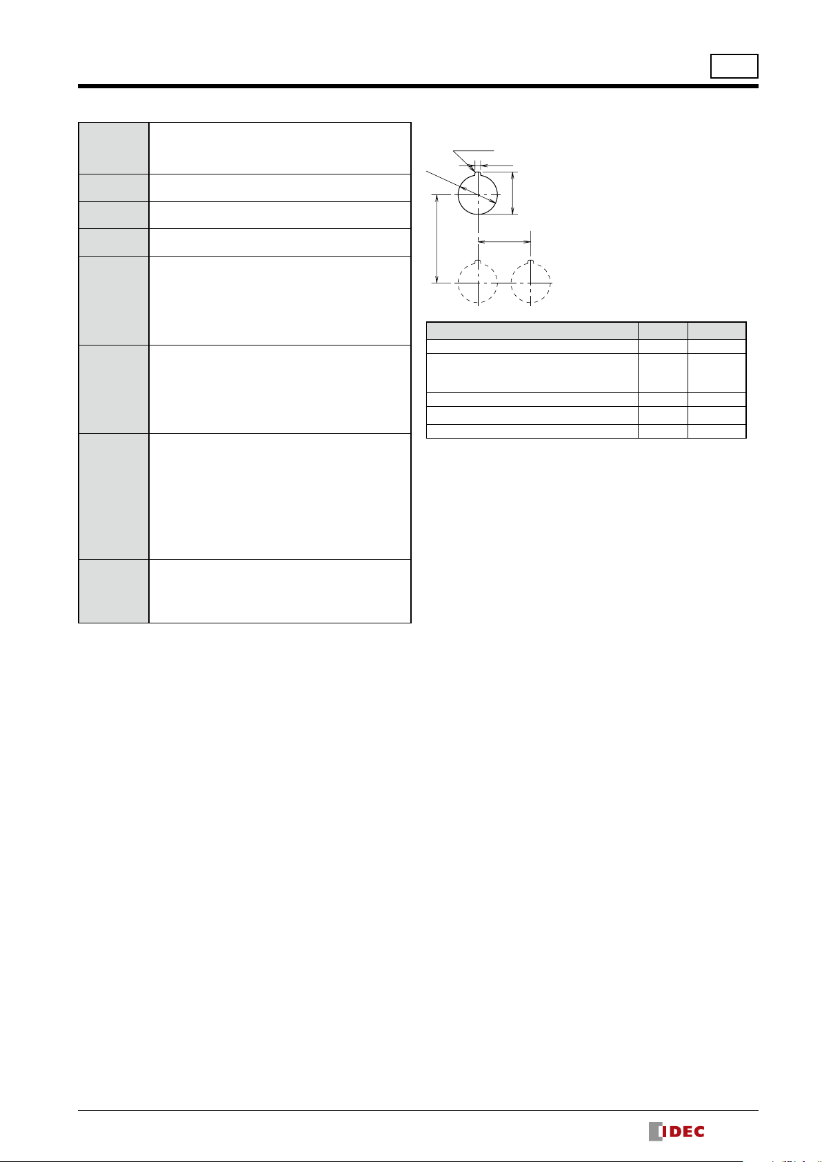
Mounting Hole Layout
The 3.2-mm-wide key recess
+0.2
ø22.3
3.2
+0.4
0
A
Emergency stop switch 50 min. 50 min.
Pushbutton
Selector switch
Key selector switch
Mushroom pushbutton 50 min. 40 min.
Pilot light (with removable lamp terminal)
Pilot light (unibody) 50 min. 30 min.
∗ Keep a minimum spacing of 50 mm when using a lamp of over 1W.
is necessary
0
ring is used.
0
+0.4
24.1
B
Unit A (mm) B (mm)
50 min. 30 min.
30 min.∗
30 min.
5
Page 6

ø22
28.6
30
ø40
M3.5 Terminal Screw
Contact Block
101010
Panel Thickness 0.8 to 6
32.545.8
Locking Ring
Gasket
41.4
28.6
101010
30
ø40
M3.5 Terminal Screw
M3.5 Terminal Screw
Full-Voltage Adapter
Contact Block
Locking Ring
Panel Thickness 0.8 to 6
45.8
32.5
Gasket
41.4
YW Series Emergency Stop Switches
Emergency Stop Switches (Pushlock Pull/Turn Reset)
Contact Block Mounting Position
1 2 3
ø40mm Mushroom
Style Contact
1NC — — NC YW1B-V4E01R
2NC NC — NC YW1B-V4E02R
Package Quantity: 1
Part No. Button Color Code
3NC NC NC NC YW1B-V4E03R
1NO-1NC NO — NC YW1B-V4E11R
1NO-2NC NO NC NC YW1B-V4E12R
2NO-1NC NO NC NO YW1B-V4E21R
• When pressed, the button is locked in the depressed position, and is reset when either pulled or turned clockwise.
Dimensions
Illuminated Emergency Stop Switches (Pushlock Pull/Turn Reset)
Contact Block Mounting
Style Lamp Contacts
ø40mm Mushroom
Without
Lamp
1NC — FA NC
2NC NC FA NC
1NO-1NC NO FA NC
1NC — FA NC
LED
2NC NC FA NC
1NO-1NC NO FA NC
1NC — FA NC
Incandescent
2NC NC FA NC
1NO-1NC NO FA NC
• Specify an operating voltage code in place of
in the Part No. FA: Full voltage adapter
➂
• When pressed, the button is locked in the depressed position, and is reset when either pulled or turned clockwise.
Dimensions
Position
1 2 3
Part No.
YW1L-V4E01Q0R
YW1L-V4E02Q0R
YW1L-V4E11Q0R
YW1L-V4E01Q
YW1L-V4E02Q
YW1L-V4E11Q
YW1L-V4E01Q
YW1L-V4E02Q
YW1L-V4E11Q
Contact Block Mounting Position
➂
Voltage Code
0: without lamp
250V AC/DC max.
2: 6V AC/DC
R
➂
➂
➂
➂
➂
➂
3: 12V AC/DC
4: 24V AC/DC
R
H: 110V AC/DC
R
M3: 230/240V AC/DC
R
5: 6V AC/DC
6: 12V AC/DC
R
7: 24V AC/DC
R
Contact Block Mounting Position
3
2
1
Operating
2
1
Red only
Package Quantity: 1
Lens Color
Code
Red only
3
6
Page 7

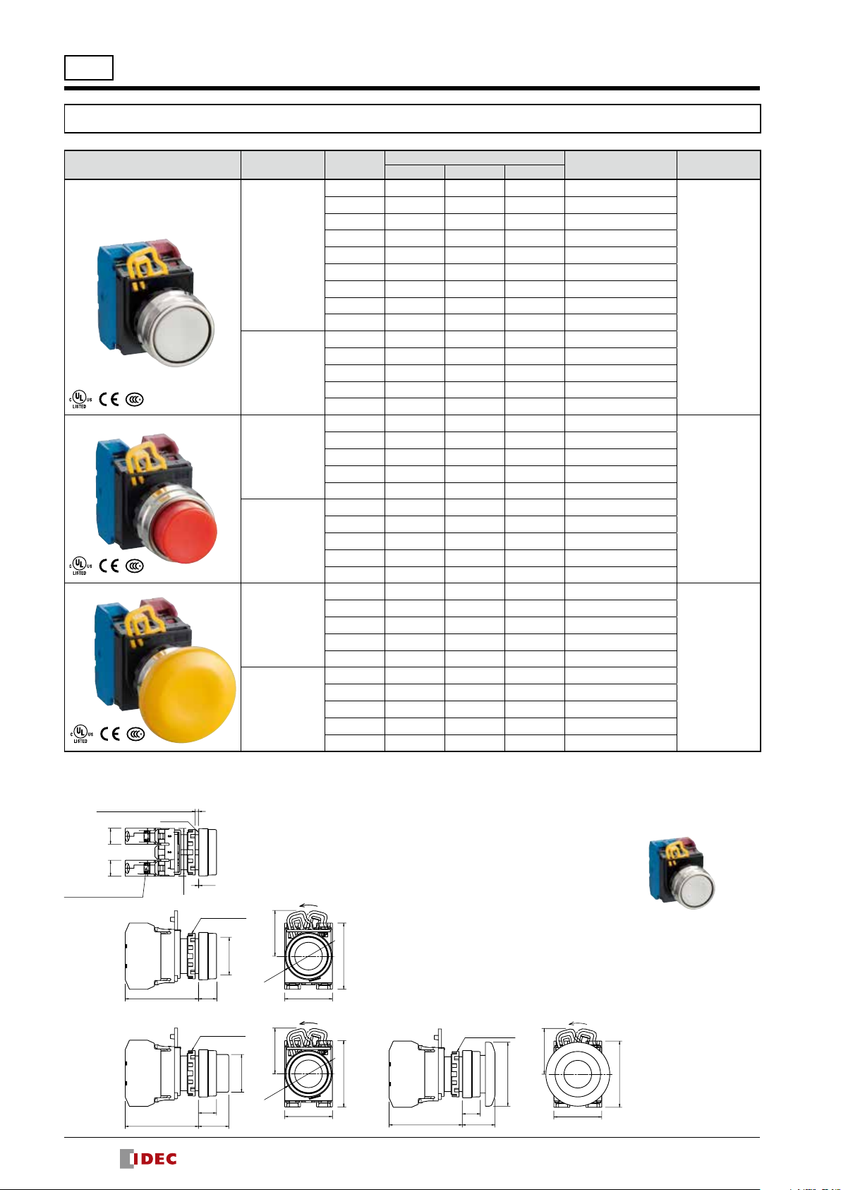
Pushbuttons with Plastic Bezel
Contact Block
M3.5
Panel Thickness: 0.8 to 6
Shape Operation Contact
Flush
Momentary
Maintained
Extended
Momentary
Maintained
Mushroom ø40mm
Momentary
Maintained
Note: Specify a button color code in place of ➀ in the Part No.
YW Series Pushbuttons
Contact Block Mounting Position
1 2 3
1NO NO — —
1NC — — NC
2NO NO — NO
2NC NC — NC
1NO-1NC NO — NC
3NO NO NO NO
3NC NC NC NC
2NO-1NC NO NC NO
1NO-2NC NO NC NC
1NO NO — —
1NC — — NC
2NO NO — NO
2NC NC — NC
1NO-1NC NO — NC
1NO NO — —
1NC — — NC
2NO NO — NO
2NC NC — NC
1NO-1NC NO — NC
1NO NO — —
1NC — — NC
2NO NO — NO
2NC NC — NC
1NO-1NC NO — NC
1NO NO — —
1NC — — NC
2NO NO — NO
2NC NC — NC
1NO-1NC NO — NC
1NO NO — —
1NC — — NC
2NO NO — NO
2NC NC — NC
1NO-1NC NO — NC
Part No.
YW1B-M1E10➀
YW1B-M1E01➀
YW1B-M1E20➀
YW1B-M1E02➀
YW1B-M1E11➀
YW1B-M1E30➀
YW1B-M1E03➀
YW1B-M1E21➀
YW1B-M1E12➀
YW1B-A1E10➀
YW1B-A1E01➀
YW1B-A1E20➀
YW1B-A1E02➀
YW1B-A1E11➀
YW1B-M2E10➀
YW1B-M2E01➀
YW1B-M2E20➀
YW1B-M2E02➀
YW1B-M2E11➀
YW1B-A2E10➀
YW1B-A2E01➀
YW1B-A2E20➀
YW1B-A2E02➀
YW1B-A2E11➀
YW1B-M4E10➀
YW1B-M4E01➀
YW1B-M4E20➀
YW1B-M4E02➀
YW1B-M4E11➀
YW1B-A4E10➀
YW1B-A4E01➀
YW1B-A4E20➀
YW1B-A4E02➀
YW1B-A4E11➀
ø22
Package Quantity: 1
Button Color
➀
Code
B: black
G: green
R: red
S: blue
W: white
Y: yellow
B: black
G: green
R: red
S: blue
W: white
Y: yellow
B: black
G: green
R: red
S: blue
W: white
Y: yellow
Emergency Stop Switches Pushbuttons Pilot Lights Illuminated Pushbuttons Selector Switches Key Selector Switches
Dimensions
Terminal Screw
Flush
Extended
Gasket
10 10
45.811
45.8
0.5
Locking Ring
ø23.6
11
19
28.6
ø29
(Button Diameter)
28.6
ø23.6
ø29
(Button Diameter)
Lock
41.4
30
Mushroom
41.4
30
45.8
ø40
11
20.5
(Button Diameter)
Contact Block Mounting Position
28.6
41.4
30
3
2
1
All dimensions in mm.
7
Page 8
ø22
Contact Block
M3.5
Panel Thickness: 0.8 to 6
YW Series Pushbuttons
Pushbuttons with Metal Bezel
Shape Operation Contact
Flush
Momentary
Maintained
Extended
Momentary
Maintained
Mushroom ø40mm
Momentary
Maintained
Note: Specify a button color code in place of ➀ in the Part No.
Contact Block Mounting Position
1 2 3
1NO NO — —
1NC — — NC
2NO NO — NO
2NC NC — NC
1NO-1NC NO — NC
3NO NO NO NO
3NC NC NC NC
2NO-1NC NO NC NO
1NO-2NC NO NC NC
1NO NO — —
1NC — — NC
2NO NO — NO
2NC NC — NC
1NO-1NC NO — NC
1NO NO — —
1NC — — NC
2NO NO — NO
2NC NC — NC
1NO-1NC NO — NC
1NO NO — —
1NC — — NC
2NO NO — NO
2NC NC — NC
1NO-1NC NO — NC
1NO NO — —
1NC — — NC
2NO NO — NO
2NC NC — NC
1NO-1NC NO — NC
1NO NO — —
1NC — — NC
2NO NO — NO
2NC NC — NC
1NO-1NC NO — NC
Part No.
YW4B-M1E10➀
YW4B-M1E01➀
YW4B-M1E20➀
YW4B-M1E02➀
YW4B-M1E11➀
YW4B-M1E30➀
YW4B-M1E03➀
YW4B-M1E21➀
YW4B-M1E12➀
YW4B-A1E10➀
YW4B-A1E01➀
YW4B-A1E20➀
YW4B-A1E02➀
YW4B-A1E11➀
YW4B-M2E10➀
YW4B-M2E01➀
YW4B-M2E20➀
YW4B-M2E02➀
YW4B-M2E11➀
YW4B-A2E10➀
YW4B-A2E01➀
YW4B-A2E20➀
YW4B-A2E02➀
YW4B-A2E11➀
YW4B-M4E10➀
YW4B-M4E01➀
YW4B-M4E20➀
YW4B-M4E02➀
YW4B-M4E11➀
YW4B-A4E10➀
YW4B-A4E01➀
YW4B-A4E20➀
YW4B-A4E02➀
YW4B-A4E11➀
Package Quantity: 1
Button Color
➀
Code
B: black
G: green
R: red
S: blue
W: white
Y: yellow
B: black
G: green
R: red
S: blue
W: white
Y: yellow
B: black
G: green
R: red
S: blue
W: white
Y: yellow
Dimensions
Terminal Screw
Flush
Extended
8
Gasket
10 10
45.819
29.8
0.3
Locking Ring
11.345.8
Locking Ring
11.3
ø23.6
(Button Diameter)
ø23.6
(Button Diameter)
ø29.5
ø29.5
28.6
28.6
Lock
Lock
41.4
30
Mushroom
41.4
30
45.8
Locking Ring
11.3
20.5
ø40
(Button Diameter)
Lock
28.6
41.4
30
3
2
1
All dimensions in mm.
Contact Block Mounting Position
Page 9
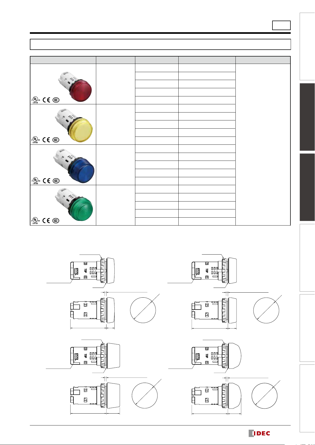
Pilot Lights (Unibody)
Flush
ø29.8
Extended
Flush Marking
Shape Lamp Operating Voltage Part No.
Flush
Full Voltage
Flush Marking
Full Voltage
Extended
Full Voltage
Dome
Full Voltage
LED
LED
LED
LED
6V AC/DC
12V AC/DC
24V AC/DC
100/110V AC
230/240V AC
6V AC/DC
12V AC/DC
24V AC/DC
100/110V AC
230/240V AC
6V AC/DC
12V AC/DC
24V AC/DC
100/110V AC
230/240V AC
6V AC/DC
12V AC/DC
24V AC/DC
100/110V AC
230/240V AC
YW Series Pilot Lights
YW1P-1UQ2➁
YW1P-1UQ3➁
YW1P-1UQ4➁
YW1P-1UQH➁
YW1P-1UQM3➁
YW1P-1BUQ2➁
YW1P-1BUQ3➁
YW1P-1BUQ4➁
YW1P-1BUQH➁
YW1P-1BUQM3➁
YW1P-2TUQ2➁
YW1P-2TUQ3➁
YW1P-2TUQ4➁
YW1P-2TUQH➁
YW1P-2TUQM3➁
YW1P-2UQ2➁
YW1P-2UQ3➁
YW1P-2UQ4➁
YW1P-2UQH➁
YW1P-2UQM3➁
A: amber
G: green
PW: pure white
R: red
S: blue
W: white
Y: yellow
Package Quantity: 1
Lens Color Code
➁
Emergency Stop Switches Pushbuttons Pilot Lights Illuminated Pushbuttons Selector Switches Key Selector Switches
ø22
Dimensions
M3.5
Terminal Screw
M3.5
Terminal Screw
Locking Ring
Gasket
42.0 9.5
Locking Ring
Gasket
Panel Thickness 0.8 to 6
Panel Thickness 0.8 to 6
ø29.8
ø29.8
M3.5
Terminal Screw
Dome
M3.5
Terminal Screw
Locking Ring
Gasket
Locking Ring
Gasket
Panel Thickness 0.8 to 6
1042.0
Panel Thickness 0.8 to 6
ø29.8
15.542.0
15.542.0
All dimensions in mm.
9
Page 10

ø22
YW Series Pilot Lights
Pilot Lights (with Removable Lamp Terminal)
Shape Lamp Operating Voltage Part No.
Flush
Full Voltage
Flush
Transformer
Flush Marking
Full Voltage
Flush Marking
Transformer
Note: Specify a lens color code in place of ➁ in the Part No.
Clear lenses are used for PW (pure white) illumination of pilot lights.
Without Lamp 250V AC/DC max.
LED
230/240V AC/DC
Incandescent
LED
Incandescent
Without Lamp 250V AC/DC max.
LED
230/240V AC/DC
Incandescent
LED
Incandescent
6V AC/DC
12V AC/DC
24V AC/DC
110V AC/DC
6V AC/DC
12V AC/DC
24V AC/DC
100/110V AC
200/220V AC
115/120V AC
230/240V AC
100/110V AC
200/220V AC
115/120V AC
230/240V AC
6V AC/DC
12V AC/DC
24V AC/DC
110V AC/DC
6V AC/DC
12V AC/DC
24V AC/DC
100/110V AC
200/220V AC
115/120V AC
230/240V AC
100/110V AC
200/220V AC
115/120V AC
230/240V AC
YW1P-1EQ0➁
YW1P-1EQ2➁
YW1P-1EQ3➁
YW1P-1EQ4➁
YW1P-1EQH➁
YW1P-1EQM3➁
YW1P-1EQ5➁
YW1P-1EQ6➁
YW1P-1EQ7➁
YW1P-1EH2➁
YW1P-1EM2➁
YW1P-1EH22➁
YW1P-1EM42➁
YW1P-1EH5➁
YW1P-1EM5➁
YW1P-1EH25➁
YW1P-1EM45➁
YW1P-1BEQ0➁
YW1P-1BEQ2➁
YW1P-1BEQ3➁
YW1P-1BEQ4➁
YW1P-1BEQH➁
YW1P-1BEQM3➁
YW1P-1BEQ5➁
YW1P-1BEQ6➁
YW1P-1BEQ7➁
YW1P-1BEH2➁
YW1P-1BEM2➁
YW1P-1BEH22➁
YW1P-1BEM42➁
YW1P-1BEH5➁
YW1P-1BEM5➁
YW1P-1BEH25➁
YW1P-1BEM45➁
Package Quantity: 1
Lens Color Code
➁
A (amber), C (clear),
G (green), R (red), S (blue),
W (white), Y (yellow)
A (amber), G (green),
PW (pure white), R (red),
S (blue), W (white), Y (yellow)
Built-in LED lamp: LSED-➂
A (amber), C (clear),
G (green), R (red), S (blue),
W (white), Y (yellow)
Built-in incandescent lamp: LS-T➂
A (amber), G (green),
PW (pure white), R (red),
S (blue), W (white), Y (yellow)
Built-in LED lamp: LSED-6
A (amber), C (clear),
G (green), R (red), S (blue),
W (white), Y (yellow)
Built-in incandescent lamp: LS-T6
A (amber), G (green), R (red),
S (blue), W (white), Y (yellow)
A (amber), G (green),
PW (pure white), R (red),
S (blue), W (white), Y (yellow)
Built-in LED lamp: LSED-➂
A (amber), G (green), R (red),
S (blue), W (white), Y (yellow)
Built-in incandescent lamp: LS-T➂
A (amber), G (green),
PW (pure white), R (red),
S (blue), W (white), Y (yellow)
Built-in LED lamp: LSED-6
A (amber), G (green), R (red),
S (blue), W (white), Y (yellow)
Built-in incandescent lamp: LS-T6
➁
➁
➁
➁
10
Page 11

YW Series Pilot Lights
Emergency Stop Switches Pushbuttons Pilot Lights Illuminated Pushbuttons Selector Switches Key Selector Switches
ø22
Shape Lamp Operating Voltage Part No.
Extended
Full Voltage
Extended
Transformer
Dome
Full Voltage
Dome
Transformer
Note: Specify a lens color code in place of ➁ in the Part No.
Clear lenses are used for PW (pure white) illumination of pilot lights.
Without Lamp 250V AC/DC max.
LED
230/240V AC/DC
Incandescent
LED
Incandescent
Without Lamp 250V AC/DC max.
LED
230/240V AC/DC
Incandescent
LED
Incandescent
6V AC/DC
12V AC/DC
24V AC/DC
110V AC/DC
6V AC/DC
12V AC/DC
24V AC/DC
100/110V AC
200/220V AC
115/120V AC
230/240V AC
100/110V AC
200/220V AC
115/120V AC
230/240V AC
6V AC/DC
12V AC/DC
24V AC/DC
110V AC/DC
6V AC/DC
12V AC/DC
24V AC/DC
100/110V AC
200/220V AC
115/120V AC
230/240V AC
100/110V AC
200/220V AC
115/120V AC
230/240V AC
YW1P-2TEQ0➁
YW1P-2TEQ2➁
YW1P-2TEQ3➁
YW1P-2TEQ4➁
YW1P-2TEQH➁
YW1P-2TEQM3➁
YW1P-2TEQ5➁
YW1P-2TEQ6➁
YW1P-2TEQ7➁
YW1P-2TEH2➁
YW1P-2TEM2➁
YW1P-2TEH22➁
YW1P-2TEM42➁
YW1P-2TEH5➁
YW1P-2TEM5➁
YW1P-2TEH25➁
YW1P-2TEM45➁
YW1P-2EQ0➁
YW1P-2EQ2➁
YW1P-2EQ3➁
YW1P-2EQ4➁
YW1P-2EQH➁
YW1P-2EQM3➁
YW1P-2EQ5➁
YW1P-2EQ6➁
YW1P-2EQ7➁
YW1P-2EH2➁
YW1P-2EM2➁
YW1P-2EH22➁
YW1P-2EM42➁
YW1P-2EH5➁
YW1P-2EM5➁
YW1P-2EH25➁
YW1P-2EM45➁
Lens Color Code
➁
A (amber), C (clear),
G (green), R (red), S (blue),
W (white), Y (yellow)
A (amber), G (green),
PW (pure white), R (red),
S (blue), W (white), Y (yellow)
Built-in LED lamp: LSED-➂➁
A (amber), C (clear),
G (green), R (red), S (blue),
W (white), Y (yellow)
Built-in incandescent lamp: LS-T➂
A (amber), G (green),
PW (pure white), R (red),
S (blue), W (white), Y (yellow)
Built-in LED lamp: LSED-6➁
A (amber), C (clear),
G (green), R (red), S (blue),
W (white), Y (yellow)
Built-in incandescent lamp: LS-T6
A (amber), C (clear),
G (green), R (red), S (blue),
W (white), Y (yellow)
A (amber), G (green),
PW (pure white), R (red),
S (blue), W (white), Y (yellow)
Built-in LED lamp: LSED-➂➁
A (amber), C (clear),
G (green), R (red), S (blue),
W (white), Y (yellow)
Built-in incandescent lamp: LS-T➂
A (amber), G (green),
PW (pure white), R (red),
S (blue), W (white), Y (yellow)
Built-in LED lamp: LSED-6➁
A (amber), C (clear),
G (green), R (red), S (blue),
W (white), Y (yellow)
Built-in incandescent lamp: LS-T6
11
Page 12

ø22
M3.5
Panel Thickness 0.8 to 6
Panel Thickness 0.8 to 6
YW Series Pilot Lights
Dimensions (Pilot Lights with Removable Lamp Terminal)
Flush
Full Voltage
M3.5 Terminal Screw
Transformer
Terminal Screw
Gasket
Locking Ring
46.29.5
Panel Thickness 0.8 to 6
Gasket
Locking Ring
29.6
ø29.8
ø29.8
Flush Marking
Full Voltage
M3.5 Terminal Screw
24
Gasket
Locking Ring
46.2 10
ø29.8
24
29.6
Transformer
Panel Thickness 0.8 to 6
M3.5 Terminal Screw
24
Gasket
Locking Ring
ø29.8
24
Extended
Full Voltage
M3.5 Terminal Screw
Transformer
M3.5 Terminal Screw
63.3
Panel Thickness 0.8 to 6
Gasket
Locking Ring
46.2
Panel Thickness 0.8 to 6
Gasket
Locking Ring
9.5
15.5
29.6
29.6
ø29.8
ø29.8
63.3
10
29.6
Dome
Full Voltage
M3.5 Terminal Screw
24
Panel Thickness 0.8 to 6
Gasket
Locking Ring
46.2
15.5
ø29.8
24
29.6
Transformer
Panel Thickness 0.8 to 6
M3.5 Terminal Screw
Gasket
Locking Ring
ø29.8
12
63.3
15.5
29.6
24
63.3
15.5
29.6
24
Page 13

YW Series Illuminated Pushbuttons
ø22
Illuminated Pushbuttons with Plastic Bezel
Package Quantity: 1
Contact Block Mounting
Shape Lamp Operation Contact
Extended
Momentary
Without
Lamp
Maintained
Momentary
LED
Maintained
Momentary
Incandescent
Maintained
Extended with
Full Shroud
Momentary
Without
Lamp
Maintained
Momentary
LED
Maintained
Momentary
Incandescent
Maintained
Note: Specify a lens color code in place of ➁ in the Part No. FA: Full voltage adapter
Specify an operating voltage code in place of ➂ in the Part No.
1NO NO FA —
1NC — FA NC
2NO NO FA NO
2NC NC FA NC
1NO-1NC NO FA NC
1NO NO FA —
1NC — FA NC
2NO NO FA NO
2NC NC FA NC
1NO-1NC NO FA NC
1NO NO FA —
1NC — FA NC
2NO NO FA NO
2NC NC FA NC
1NO-1NC NO FA NC
1NO NO FA —
1NC — FA NC
2NO NO FA NO
2NC NC FA NC
1NO-1NC NO FA NC
1NO NO FA —
1NC — FA NC
2NO NO FA NO
2NC NC FA NC
1NO-1NC NO FA NC
1NO NO FA —
1NC — FA NC
2NO NO FA NO
2NC NC FA NC
1NO-1NC NO FA NC
1NO NO FA —
1NC — FA NC
2NO NO FA NO
2NC NC FA NC
1NO-1NC NO FA NC
1NO NO FA —
1NC — FA NC
2NO NO FA NO
2NC NC FA NC
1NO-1NC NO FA NC
1NO NO FA —
1NC — FA NC
2NO NO FA NO
2NC NC FA NC
1NO-1NC NO FA NC
1NO NO FA —
1NC — FA NC
2NO NO FA NO
2NC NC FA NC
1NO-1NC NO FA NC
1NO NO FA —
1NC — FA NC
2NO NO FA NO
2NC NC FA NC
1NO-1NC NO FA NC
1NO NO FA —
1NC — FA NC
2NO NO FA NO
2NC NC FA NC
1NO-1NC NO FA NC
Position
1 2 3
Part No.
YW1L-M2E10Q0➁
YW1L-M2E01Q0➁
YW1L-M2E20Q0➁
YW1L-M2E02Q0➁
YW1L-M2E11Q0➁
YW1L-A2E10Q0➁
YW1L-A2E01Q0➁
YW1L-A2E20Q0➁
YW1L-A2E02Q0➁
YW1L-A2E11Q0➁
YW1L-M2E10Q➂➁
YW1L-M2E01Q➂➁
YW1L-M2E20Q➂➁
YW1L-M2E02Q➂➁
YW1L-M2E11Q➂➁
YW1L-A2E10Q➂➁
YW1L-A2E01Q➂➁
YW1L-A2E20Q➂➁
YW1L-A2E02Q➂➁
YW1L-A2E11Q➂➁
YW1L-M2E10Q➂➁
YW1L-M2E01Q➂➁
YW1L-M2E20Q➂➁
YW1L-M2E02Q➂➁
YW1L-M2E11Q➂➁
YW1L-A2E10Q➂➁
YW1L-A2E01Q➂➁
YW1L-A2E20Q➂➁
YW1L-A2E02Q➂➁
YW1L-A2E11Q➂➁
YW1L-MF2E10Q0➁
YW1L-MF2E01Q0➁
YW1L-MF2E20Q0➁
YW1L-MF2E02Q0➁
YW1L-MF2E11Q0➁
YW1L-AF2E10Q0➁
YW1L-AF2E01Q0➁
YW1L-AF2E20Q0➁
YW1L-AF2E02Q0➁
YW1L-AF2E11Q0➁
YW1L-MF2E10Q➂➁
YW1L-MF2E01Q➂➁
YW1L-MF2E20Q➂➁
YW1L-MF2E02Q➂➁
YW1L-MF2E11Q➂➁
YW1L-AF2E10Q➂➁
YW1L-AF2E01Q➂➁
YW1L-AF2E20Q➂➁
YW1L-AF2E02Q➂➁
YW1L-AF2E11Q➂➁
YW1L-MF2E10Q➂➁
YW1L-MF2E01Q➂➁
YW1L-MF2E20Q➂➁
YW1L-MF2E02Q➂➁
YW1L-MF2E11Q➂➁
YW1L-AF2E10Q➂➁
YW1L-AF2E01Q➂➁
YW1L-AF2E20Q➂➁
YW1L-AF2E02Q➂➁
YW1L-AF2E11Q➂➁
Operating
➂
Voltage Code
0: without lamp
250V AC/DC max.
2: 6V AC/DC
3: 12V AC/DC
4: 24V AC/DC
H: 110V AC/DC
M3: 230/240V
AC/DC
5: 6V AC/DC
6: 12V AC/DC
7: 24V AC/DC
0: without lamp
250V AC/DC max.
2: 6V AC/DC
3: 12V AC/DC
4: 24V AC/DC
H: 110V AC/DC
M3: 230/240V
AC/DC
5: 6V AC/DC
6: 12V AC/DC
7: 24V AC/DC
Lens Color Code
➁
A: amber
G: green
R: red
S: blue
W: white
Y: yellow
A: amber
G: green
PW: pure white
R: red
S: blue
W: white
Y: yellow
Built-in LED lamp:
LSED-➂➁
A: amber
G: green
R: red
S: blue
W: white
Y: yellow
Built-in
incandescent
lamp:
LS-T
➂
A: amber
G: green
R: red
S: blue
W: white
Y: yellow
A: amber
G: green
PW: pure white
R: red
S: blue
W: white
Y: yellow
Built-in LED lamp:
LSED-➂➁
A: amber
G: green
R: red
S: blue
W: white
Y: yellow
Built-in
incandescent
lamp:
LS-T➂
Emergency Stop Switches Pushbuttons Pilot Lights Illuminated Pushbuttons Selector Switches Key Selector Switches
13
Page 14

ø22
Panel Thickness: 0.8 to 6
Extended
Mushroom
All dimensions in mm.
M3.5
Contact Block
M3.5
Full-voltage
YW Series Illuminated Pushbuttons
Shape Lamp Operation Contact
Mushroom ø40mm
Without
Lamp
LED
Incandescent
Momentary
Maintained
Momentary
Maintained
Momentary
Maintained
Contact Block Mounting
Position
1 2 3
1NO NO FA —
1NC — FA NC
2NO NO FA NO
2NC NC FA NC
1NO-1NC NO FA NC
1NO NO FA —
1NC — FA NC
2NO NO FA NO
2NC NC FA NC
1NO-1NC NO FA NC
1NO NO FA —
1NC — FA NC
2NO NO FA NO
2NC NC FA NC
1NO-1NC NO FA NC
1NO NO FA —
1NC — FA NC
2NO NO FA NO
2NC NC FA NC
1NO-1NC NO FA NC
1NO NO FA —
1NC — FA NC
2NO NO FA NO
2NC NC FA NC
1NO-1NC NO FA NC
1NO NO FA —
1NC — FA NC
2NO NO FA NO
2NC NC FA NC
1NO-1NC NO FA NC
Part No.
YW1L-M4E10Q0➁
YW1L-M4E01Q0➁
YW1L-M4E20Q0➁
YW1L-M4E02Q0➁
YW1L-M4E11Q0➁
YW1L-A4E10Q0➁
YW1L-A4E01Q0➁
YW1L-A4E20Q0➁
YW1L-A4E02Q0➁
YW1L-A4E11Q0➁
YW1L-M4E10Q➂➁
YW1L-M4E01Q➂➁
YW1L-M4E20Q➂➁
YW1L-M4E02Q➂➁
YW1L-M4E11Q➂➁
YW1L-A4E10Q➂➁
YW1L-A4E01Q➂➁
YW1L-A4E20Q➂➁
YW1L-A4E02Q➂➁
YW1L-A4E11Q➂➁
YW1L-M4E10Q➂➁
YW1L-M4E01Q➂➁
YW1L-M4E20Q➂➁
YW1L-M4E02Q➂➁
YW1L-M4E11Q➂➁
YW1L-A4E10Q➂➁
YW1L-A4E01Q➂➁
YW1L-A4E20Q➂➁
YW1L-A4E02Q➂➁
YW1L-A4E11Q➂➁
Operating
➂
Voltage Code
0: without lamp
250V AC/DC max.
2: 6V AC/DC
3: 12V AC/DC
4: 24V AC/DC
H: 110V AC/DC
M3: 230/240V
AC/DC
5: 6V AC/DC
6: 12V AC/DC
7: 24V AC/DC
Lens Color
➁
Code
A: amber
G: green
R: red
S: blue
W: white
Y: yellow
A: amber
G: green
PW: pure white
R: red
S: blue
W: white
Y: yellow
Built-in LED
lamp:
LSED-➂➁
A: amber
G: green
R: red
S: blue
W: white
Y: yellow
Built-in
incandescent
lamp:
LS-T➂
Note: Specify a lens color code in place of ➁ in the Part No. FA: Full voltage adapter
Specify an operating voltage code in place of ➂ in the Part No.
Dimensions
(Illuminated Pushbuttons with Plastic Bezel)
Terminal Screw
Adapter
10 1010
Terminal Screw
45.8
45.8
Gasket
0.5
ø23.6
(Lens Diameter)
11
19
ø40
(Lens Diameter)
11
20.5
28.628.6
ø29
Contact Block Mounting Position
3
2
1
41.441.4
30
Extended with Full Shroud
28.6
41.4
ø28.2
30
45.8
19
30
14
Page 15

YW Series Illuminated Pushbuttons
ø22
Illuminated Pushbuttons with Metal Bezel
Package Quantity: 1
Contact Block Mounting
Shape Lamp Operation Contact
Extended
Momentary
Without
Lamp
Maintained
Momentary
LED
Maintained
Momentary
Incandescent
Maintained
Extended with
Full Shroud
Momentary
Without
Lamp
Maintained
Momentary
LED
Maintained
Momentary
Incandescent
Maintained
Note: Specify a lens color code in place of ➁ in the Part No. FA: Full voltage adapter
Specify an operating voltage code in place of ➂ in the Part No.
1NO NO FA —
1NC — FA NC
2NO NO FA NO
2NC NC FA NC
1NO-1NC NO FA NC
1NO NO FA —
1NC — FA NC
2NO NO FA NO
2NC NC FA NC
1NO-1NC NO FA NC
1NO NO FA —
1NC — FA NC
2NO NO FA NO
2NC NC FA NC
1NO-1NC NO FA NC
1NO NO FA —
1NC — FA NC
2NO NO FA NO
2NC NC FA NC
1NO-1NC NO FA NC
1NO NO FA —
1NC — FA NC
2NO NO FA NO
2NC NC FA NC
1NO-1NC NO FA NC
1NO NO FA —
1NC — FA NC
2NO NO FA NO
2NC NC FA NC
1NO-1NC NO FA NC
1NO NO FA —
1NC — FA NC
2NO NO FA NO
2NC NC FA NC
1NO-1NC NO FA NC
1NO NO FA —
1NC — FA NC
2NO NO FA NO
2NC NC FA NC
1NO-1NC NO FA NC
1NO NO FA —
1NC — FA NC
2NO NO FA NO
2NC NC FA NC
1NO-1NC NO FA NC
1NO NO FA —
1NC — FA NC
2NO NO FA NO
2NC NC FA NC
1NO-1NC NO FA NC
1NO NO FA —
1NC — FA NC
2NO NO FA NO
2NC NC FA NC
1NO-1NC NO FA NC
1NO NO FA —
1NC — FA NC
2NO NO FA NO
2NC NC FA NC
1NO-1NC NO FA NC
Position
1 2 3
Part No.
YW4L-M2E10Q0➁
YW4L-M2E01Q0➁
YW4L-M2E20Q0➁
YW4L-M2E02Q0➁
YW4L-M2E11Q0➁
YW4L-A2E10Q0➁
YW4L-A2E01Q0➁
YW4L-A2E20Q0➁
YW4L-A2E02Q0➁
YW4L-A2E11Q0➁
YW4L-M2E10Q➂➁
YW4L-M2E01Q➂➁
YW4L-M2E20Q➂➁
YW4L-M2E02Q➂➁
YW4L-M2E11Q➂➁
YW4L-A2E10Q➂➁
YW4L-A2E01Q➂➁
YW4L-A2E20Q➂➁
YW4L-A2E02Q➂➁
YW4L-A2E11Q➂➁
YW4L-M2E10Q➂➁
YW4L-M2E01Q➂➁
YW4L-M2E20Q➂➁
YW4L-M2E02Q➂➁
YW4L-M2E11Q➂➁
YW4L-A2E10Q➂➁
YW4L-A2E01Q➂➁
YW4L-A2E20Q➂➁
YW4L-A2E02Q➂➁
YW4L-A2E11Q➂➁
YW4L-MF2E10Q0➁
YW4L-MF2E01Q0➁
YW4L-MF2E20Q0➁
YW4L-MF2E02Q0➁
YW4L-MF2E11Q0➁
YW4L-AF2E10Q0➁
YW4L-AF2E01Q0➁
YW4L-AF2E20Q0➁
YW4L-AF2E02Q0➁
YW4L-AF2E11Q0➁
YW4L-MF2E10Q➂➁
YW4L-MF2E01Q➂➁
YW4L-MF2E20Q➂➁
YW4L-MF2E02Q➂➁
YW4L-MF2E11Q➂➁
YW4L-AF2E10Q➂➁
YW4L-AF2E01Q➂➁
YW4L-AF2E20Q➂➁
YW4L-AF2E02Q➂➁
YW4L-AF2E11Q➂➁
YW4L-MF2E10Q➂➁
YW4L-MF2E01Q➂➁
YW4L-MF2E20Q➂➁
YW4L-MF2E02Q➂➁
YW4L-MF2E11Q➂➁
YW4L-AF2E10Q➂➁
YW4L-AF2E01Q➂➁
YW4L-AF2E20Q➂➁
YW4L-AF2E02Q➂➁
YW4L-AF2E11Q➂➁
Operating
➂
Voltage Code
0: without lamp
250V AC/DC max.
2: 6V AC/DC
3: 12V AC/DC
4: 24V AC/DC
H: 110V AC/DC
M3: 230/240V
AC/DC
5: 6V AC/DC
6: 12V AC/DC
7: 24V AC/DC
0: without lamp
250V AC/DC max.
2: 6V AC/DC
3: 12V AC/DC
4: 24V AC/DC
H: 110V AC/DC
M3: 230/240V
AC/DC
5: 6V AC/DC
6: 12V AC/DC
7: 24V AC/DC
Lens Color Code
➁
A: amber
G: green
R: red
S: blue
W: white
Y: yellow
A: amber
G: green
PW: pure white
R: red
S: blue
W: white
Y: yellow
Built-in LED lamp:
LSED-➂➁
A: amber
G: green
R: red
S: blue
W: white
Y: yellow
Built-in
incandescent
lamp:
LS-T➂
A: amber
G: green
R: red
S: blue
W: white
Y: yellow
A: amber
G: green
PW: pure white
R: red
S: blue
W: white
Y: yellow
Built-in LED lamp:
LSED-➂➁
A: amber
G: green
R: red
S: blue
W: white
Y: yellow
Built-in
incandescent
lamp:
LS-T➂
Emergency Stop Switches Pushbuttons Pilot Lights Illuminated Pushbuttons Selector Switches Key Selector Switches
15
Page 16

ø22
ø40
20.5
11.3
45.8
Locking Ring
Flush Mushroom
Extended
41.4
28.6
30
Lock
ø29.5
41.4
28.6
30
Lock
(Button Diameter)
(Button Diameter)
ø23.6
11.3
45.8 19
Locking Ring
(Button Diameter)
ø29.5
41.4
28.6
30
Lock
ø23.6
11.345.8
Locking Ring
29.8
10 10
0.3
Gasket
Panel Thickness: 0.8 to 6
YW Series Illuminated Pushbuttons
Contact Block Mounting
Style Lamp Operation Contact
1 2 3
ø40mm Mushroom
1NO NO FA —
1NC — FA NC
Momentary
2NO NO FA NO
2NC NC FA NC
Without
Lamp
1NO-1NC NO FA NC
1NO NO FA —
1NC — FA NC
Maintained
2NO NO FA NO
2NC NC FA NC
1NO-1NC NO FA NC
1NO NO FA —
1NC — FA NC
Momentary
2NO NO FA NO
2NC NC FA NC
LED
Incan-
Maintained
Momentary
descent
Note: Specify a lens color code in place of
Specify an operating voltage code in place of ➂ in the Part No.
Dimensions (Illuminated Pushbutton with Metal Bezel)
Panel Thickness: 0.8 to 6
M3.5 Terminal Screw
Full-voltage Adapter
Gasket
Maintained
in the Part No. FA: Full voltage adapter
➁
1NO-1NC NO FA NC
1NO NO FA —
1NC — FA NC
2NO NO FA NO
2NC NC FA NC
1NO-1NC NO FA NC
1NO NO FA —
1NC — FA NC
2NO NO FA NO
2NC NC FA NC
1NO-1NC NO FA NC
1NO NO FA —
1NC — FA NC
2NO NO FA NO
2NC NC FA NC
1NO-1NC NO FA NC
Position
Part No.
YW4L-M4E10Q0➁
YW4L-M4E01Q0➁
YW4L-M4E20Q0➁
YW4L-M4E02Q0➁
YW4L-M4E11Q0➁
YW4L-A4E10Q0➁
YW4L-A4E01Q0➁
YW4L-A4E20Q0➁
YW4L-A4E02Q0➁
YW4L-A4E11Q0➁
YW4L-M4E10Q➂➁
YW4L-M4E01Q➂➁
YW4L-M4E20Q➂➁
YW4L-M4E02Q➂➁
YW4L-M4E11Q➂➁
YW4L-A4E10Q➂➁
YW4L-A4E01Q➂➁
YW4L-A4E20Q➂➁
YW4L-A4E02Q➂➁
YW4L-A4E11Q➂➁
YW4L-M4E10Q➂➁
YW4L-M4E01Q➂➁
YW4L-M4E20Q➂➁
YW4L-M4E02Q➂➁
YW4L-M4E11Q➂➁
YW4L-A4E10Q➂➁
YW4L-A4E01Q➂➁
YW4L-A4E20Q➂➁
YW4L-A4E02Q➂➁
YW4L-A4E11Q➂➁
Operating
➂
➁
Voltage Code
A: amber
G: green
0: without lamp
250V AC/DC max.
R: red
S: blue
W: white
Y: yellow
A: amber
G: green
PW: pure white
R: red
S: blue
W: white
Y: yellow
Built-in LED
2: 6V AC/DC
3: 12V AC/DC
4: 24V AC/DC
H: 110V AC/DC
M3: 230/240V
AC/DC
lamp:
LSED-➂➁
A: amber
G: green
R: red
5: 6V AC/DC
6: 12V AC/DC
7: 24V AC/DC
S: blue
W: white
Y: yellow
Built-in
incandescent
lamp:
LS-T➂
Contact Block Mounting Position
3
2
1
Lens Color
Code
M3.5 Terminal Screw
Contact Block
Extended
Mushroom
16
10 1010
45.8 19
45.8
0.3
Locking Ring
11.3
Locking Ring
11.3
20.5
ø23.6
(Lens Diameter)
ø40
(Lens Diameter)
ø29.5
28.6
28.6
Lock
30
Lock
41.4
Extended with Full Shroud
Locking Ring
41.4
30
45.8 19.2
ø23.6
(Lens Diameter)
Lock
28.6
41.4
ø29.5
30
All dimensions in mm.
Page 17

Selector Switches with Plastic Bezel
LR
L
C
R
Shape
Knob
YW Series Selector Switches
Package Quantity: 1
Emergency Stop Switches Pushbuttons Pilot Lights Illuminated Pushbuttons Selector Switches Key Selector Switches
ø22
No. of
Positions
90°
2-Position
No. of
Positions
45°
3-Position
Contact
Conguration
1NO
(10)
1NC
(01)
2NO
(20)
2NC
(02)
1NO-1NC
(11)
3NO
(30)
3NC
(03)
2NO-1NC
(21)
1NO-2NC
(12)
Contact
Conguration
2NO
(20)
2NO
(20N1)
2NC
(02)
2NC
(02N1)
1NO-1NC
(11)
1NO-1NC
(11N1)
1NO-1NC
(11N2)
1NO-1NC
(11N3)
1NO-1NC
(11N4)
3NO
(30)
3NC
(03)
2NO-1NC
(21)
1NO-2NC
(12)
Contact Block
Mounting Position
1 NO ●
2
3
1
3 NC ●
1 NO ●
3 NO ●
1 NC ●
3 NC ●
1 NO ●
3 NC ●
1 NO ●
3 NO ●
1 NC ●
3 NC ●
1 NO ●
3 NO ●
1 NO ●
3 NC ●
Contact Block
Mounting Position
1 NO ●
2
3 NO ●
1
3 NO ●
1 NC
3 NC
1
3 NC
1 NO ●
3 NC
1 NC
3 NO ●
1 NO ●
3
1
3 NO ●
1
3 NC
1 NO ●
3 NO ●
1 NC
3 NC
1 NO ●
3 NO ●
1 NC
3 NC
Operator Position
L R –
Operator Position
L C R
Maintained
YW1S-2E10 YW1S-21E10 — —
YW1S-2E01 YW1S-21E01 — —2
YW1S-2E20 YW1S-21E20 — —2
YW1S-2E02 YW1S-21E02 — —2
YW1S-2E11 YW1S-21E11 — —2
YW1S-2E30 YW1S-21E30 — —2 NO ●
YW1S-2E03 YW1S-21E03 — —2 NC ●
YW1S-2E21 YW1S-21E21 — —2 NC ●
YW1S-2E12 YW1S-21E12 — —2 NC ●
Maintained
YW1S-3E20 YW1S-31E20 YW1S-32E20 YW1S-33E20
YW1S-3E20N1 YW1S-31E20N1 YW1S-32E20N1 YW1S-33E20N12 NO ● ●
YW1S-3E02 YW1S-31E02 YW1S-32E02 YW1S-33E022
YW1S-3E02N1 YW1S-31E02N1 YW1S-32E02N1 YW1S-33E02N12 NC ●
YW1S-3E11 YW1S-31E11 YW1S-32E11 YW1S-33E112
YW1S-3E11N1 YW1S-31E11N1 YW1S-32E11N1 YW1S-33E11N12
YW1S-3E11N2 YW1S-31E11N2 YW1S-32E11N2 YW1S-33E11N22 NC ●
YW1S-3E11N3 YW1S-31E11N3 YW1S-32E11N3 YW1S-33E11N32 NC ●
YW1S-3E11N4 YW1S-31E11N4 YW1S-32E11N4 YW1S-33E11N42 NO ● ●
YW1S-3E30 YW1S-31E30 YW1S-32E30 YW1S-33E302 NO ● ●
YW1S-3E03 YW1S-31E03 YW1S-32E03 YW1S-33E032 NC ●
YW1S-3E21 YW1S-31E21 YW1S-32E21 YW1S-33E212 NC ●
YW1S-3E12 YW1S-31E12 YW1S-32E12 YW1S-33E122 NO ● ●
Spring Return
from Right
Spring Return
from Right
— —
Spring Return
from Left
Spring Return
Two-Way
17
Page 18

ø22
LR
L
C
R
YW Series Selector Switches
Selector Switches with Metal Bezel
Shape
Package Quantity: 1
Knob
No. of
Positions
90°
2-Position
No. of
Positions
45°
3-Position
Contact
Conguration
1NO
(10)
1NC
(01)
2NO
(20)
2NC
(02)
1NO-1NC
(11)
3NO
(30)
3NC
(03)
2NO-1NC
(21)
1NO-2NC
(12)
Contact
Conguration
2NO
(20)
2NO
(20N1)
2NC
(02)
2NC
(02N1)
1NO-1NC
(11)
1NO-1NC
(11N1)
1NO-1NC
(11N2)
1NO-1NC
(11N3)
1NO-1NC
(11N4)
3NO
(30)
3NC
(03)
2NO-1NC
(21)
1NO-2NC
(12)
Contact Block
Mounting Position
1 NO ●
2
3
1
2
3 NC ●
1 NO ●
2
3 NO ●
1 NC ●
2
3 NC ●
1 NO ●
2
3 NC ●
1 NO ●
2 NO ●
3 NO ●
1 NC ●
2 NC ●
3 NC ●
1 NO ●
2 NC ●
3 NO ●
1 NO ●
2 NC ●
3 NC ●
Contact Block
Mounting Position
1 NO ●
2
3 NO ●
1
2 NO ● ●
3 NO ●
1 NC
2
3 NC
1
2 NC ●
3 NC
1 NO ●
2
3 NC
1 NC
2
3 NO ●
1 NO ●
2 NC ●
3
1
2 NC ●
3 NO ●
1
2 NO ● ●
3 NC
1 NO ●
2 NO ● ●
3 NO ●
1 NC
2 NC ●
3 NC
1 NO ●
2 NC ●
3 NO ●
1 NC
2 NO ● ●
3 NC
Operator Position
L R –
Operator Position
L C R
Maintained
YW4S-2E10 YW4S-21E10 — —
YW4S-2E01 YW4S-21E01 — —
YW4S-2E20 YW4S-21E20 — —
YW4S-2E02 YW4S-21E02 — —
YW4S-2E11 YW4S-21E11 — —
YW4S-2E30 YW4S-21E30 — —
YW4S-2E03 YW4S-21E03 — —
YW4S-2E21 YW4S-21E21 — —
YW4S-2E12 YW4S-21E12 — —
Maintained
YW4S-3E20 YW4S-31E20 YW4S-32E20 YW4S-33E20
YW4S-3E20N1 YW4S-31E20N1 YW4S-32E20N1 YW4S-33E20N1
YW4S-3E02 YW4S-31E02 YW4S-32E02 YW4S-33E02
YW4S-3E02N1 YW4S-31E02N1 YW4S-32E02N1 YW4S-33E02N1
YW4S-3E11 YW4S-31E11 YW4S-32E11 YW4S-33E11
YW4S-3E11N1 YW4S-31E11N1 YW4S-32E11N1 YW4S-33E11N1
YW4S-3E11N2 YW4S-31E11N2 YW4S-32E11N2 YW4S-33E11N2
YW4S-3E11N3 YW4S-31E11N3 YW4S-32E11N3 YW4S-33E11N3
YW4S-3E11N4 YW4S-31E11N4 YW4S-32E11N4 YW4S-33E11N4
YW4S-3E30 YW4S-31E30 YW4S-32E30 YW4S-33E30
YW4S-3E03 YW4S-31E03 YW4S-32E03 YW4S-33E03
YW4S-3E21 YW4S-31E21 YW4S-32E21 YW4S-33E21
YW4S-3E12 YW4S-31E12 YW4S-32E12 YW4S-33E12
Spring Return
from Right
Spring Return
from Right
— —
Spring Return
from Left
Spring Return
Two-Way
18
Page 19

L
C
R
Panel Thickness: 0.8 to 6
3-Position
Diameter
2-Position
L
C
R
ø40
20.5
11.3
45.8
Extended
Extended
Gasket
Full-voltage Adapter
M3.5 Terminal Screw
10 1010
0.3
Panel Thickness: 0.8 to 6
Contact Block
M3.5 Terminal Screw
Extended with Full Shroud
41.4
ø29.5
28.6
30
Lock
ø23.6
(Lens Diameter)
Locking Ring
45.8 19.2
41.4
28.6
30
ø29.5
41.4
28.6
30
Lock
(Button Diameter)
(Button Diameter)
Mushroom
41.4
28.6
30
Lock
ø40
20.5
11.3
45.8
Locking Ring
(Lens Diameter)
ø23.6
11.3
45.8 19
Locking Ring
(Button Diameter)
ø29.5
41.4
28.6
30
Lock
ø23.6
11.3
45.8 19
Locking Ring
(Lens Diameter)
ø29.5
41.4
28.6
30
ø23.6
11.345.8
Contact Block Mounting Position
Selector Switch with Plastic Bezel
Contact Block
Mounting Position
3
2
1
Operator Position
YW Series Selector Switches
Emergency Stop Switches Pushbuttons Pilot Lights Illuminated Pushbuttons Selector Switches Key Selector Switches
ø22
Dimensions
Selector Switch with Plastic Bezel
10 10
M3.5 Terminal Screw
Contact Block
Gasket
45.8
0.5
Locking Ring
11
24
45°
90°
Lock
45°
Selector Switch with Metal Bezel Selector Switch with Metal Bezel
Contact Block
Mounting Position
2
1
3
Operator Position
0.3
Locking Ring
11.3
24
M3.5 Terminal Screw
Contact Block
Panel Thickness: 0.8 to 6
10 10
Gasket
45.8
28.6
45°
41.4
ø27.6
Knob
2-position
41.4
ø29
30
90°
Lock
28.6
ø29.5
30
45°
Lock
28.6
3-position
41.4
ø29.5
30
All dimensions in mm.
19
Page 20

ø22
LR
LR
YW Series Key Selector Switches
Key Selector Switches (90° 2-Position)
Operator Position
Package Quantity: 1
Part No.
Plastic Bezel Metal Bezel
No. of Positions
90° 2-position
Maintained
90° 2-position
Spring Return from Right
• On the spring-returned types, the key can be removed only from the maintained position. On the maintained types, the key can be removed from every position.
Key retained positions are also available. See Part No. Development shown on page 21.
• Each key selector switch is supplied with two identical keys.
Contact
Conguration
1NO
(10)
1NC
(01)
2NO
(20)
2NC
(02)
1NO-1NC
(11)
3NO
(30)
3NC
(03)
2NO-1NC
(21)
1NO-2NC
(12)
1NO
(10)
1NC
(01)
2NO
(20)
2NC
(02)
1NO-1NC
(11)
3NO
(30)
3NC
(03)
2NO-1NC
(21)
1NO-2NC
(12)
Contact Block
Mounting Position
1 NO ●
3
1
3 NC ●
1 NO ●
3 NO ●
1 NC ●
3 NC ●
1 NO ●
3 NC ●
1 NO ●
3 NO ●
1 NC ●
3 NC ●
1 NO ●
3 NO ●
1 NO ●
3 NC ●
1 NO ●
3
1
3 NC ●
1 NO ●
3 NO ●
1 NC ●
3 NC ●
1 NO ●
3 NC ●
1 NO ●
3 NO ●
1 NC ●
3 NC ●
1 NO ●
3 NO ●
1 NO ●
3 NC ●
L R
YW1K-2AE10 YW4K-2AE102
YW1K-2AE01 YW4K-2AE012
YW1K-2AE20 YW4K-2AE202
YW1K-2AE02 YW4K-2AE022
YW1K-2AE11 YW4K-2AE112
YW1K-2AE30 YW4K-2AE302 NO ●
YW1K-2AE03 YW4K-2AE032 NC ●
YW1K-2AE21 YW4K-2AE212 NC ●
YW1K-2AE12 YW4K-2AE122 NC ●
YW1K-21BE10 YW4K-21BE102
YW1K-21BE01 YW4K-21BE012
YW1K-21BE20 YW4K-21BE202
YW1K-21BE02 YW4K-21BE022
YW1K-21BE11 YW4K-21BE112
YW1K-21BE30 YW4K-21BE302 NO ●
YW1K-21BE03 YW4K-21BE032 NC ●
YW1K-21BE21 YW4K-21BE212 NC ●
YW1K-21BE12 YW4K-21BE122 NC ●
20
Page 21

L
C
R
L
C
Key Selector Switches (45° 3-Position)
YW Series Key Selector Switches
Operator Position
Emergency Stop Switches Pushbuttons Pilot Lights Illuminated Pushbuttons Selector Switches Key Selector Switches
ø22
Package Quantity: 1
Part No.
Plastic Bezel Metal Bezel
No. of Positions
45° 3-position
Maintained
• On the maintained types, the key can be removed from every position. Key retained positions are also available. See Part No. Development below.
• Each key selector switch is supplied with two identical keys.
Contact
Conguration
2NO
(20)
2NO
(20N1)
2NC
(02)
2NC
(02N1)
1NO-1NC
(11)
1NO-1NC
(11N1)
1NO-1NC
(11N2)
1NO-1NC
(11N3)
1NO-1NC
(11N4)
3NO
(30)
3NC
(03)
2NO-1NC
(21)
1NO-2NC
(12)
Contact Block
Mounting Position
1 NO ●
3 NO ●
1
3 NO ●
1 NC
3 NC
1
3 NC
1 NO ●
3 NC
1 NC
3 NO ●
1 NO ●
3
1
3 NO ●
1
3 NC
1 NO ●
3 NO ●
1 NC
3 NC
1 NO ●
3 NO ●
1 NC
3 NC
L C R
YW1K-3AE20 YW4K-3AE202
YW1K-3AE20N1 YW4K-3AE20N12 NO ● ●
YW1K-3AE02 YW4K-3AE022
YW1K-3AE02N1 YW4K-3AE02N12 NC ●
YW1K-3AE11 YW4K-3AE112
YW1K-3AE11N1 YW4K-3AE11N12
YW1K-3AE11N2 YW4K-3AE11N22 NC ●
YW1K-3AE11N3 YW4K-3AE11N32 NC ●
YW1K-3AE11N4 YW4K-3AE11N42 NO ● ●
YW1K-3AE30 YW4K-3AE302 NO ● ●
YW1K-3AE03 YW4K-3AE032 NC ●
YW1K-3AE21 YW4K-3AE212 NC ●
YW1K-3AE12 YW4K-3AE122 NO ● ●
Part No. Development Contact Block Mounting Position
YW1K-2 A E21
Key removal position code
2-position
A: Removable in all positions
B: Removable in left only
C: Removable in right only
3-position
A: Removable in all positions
B: Removable in left and center
C: Removable in right and center
D: Removable in center only
E: Removable in right and left
G: Removable in left only
H: Removable in right only
Contact Block Mounting
Position
3
2
1
R
Operator Position
21
Page 22

ø22
L
C
R
YW Series Key Selector Switches
Key Selector Switches (45° 3-Position)
Operator Position
Package Quantity: 1
Part No.
Plastic Bezel Metal Bezel
No. of Positions
45° 3-position
Spring Return from
Right
• On the spring-returned types, the key can be removed only from the maintained position. Key retained positions are also available. See Part No. Development shown
on page 21.
• Each key selector switch is supplied with two identical keys.
Contact
Conguration
2NO
(20)
2NO
(20N1)
2NC
(02)
2NC
(02N1)
1NO-1NC
(11)
1NO-1NC
(11N1)
1NO-1NC
(11N2)
1NO-1NC
(11N3)
1NO-1NC
(11N4)
3NO
(30)
3NC
(03)
2NO-1NC
(21)
1NO-2NC
(12)
Contact Block
Mounting Position
1 NO ●
3 NO ●
1
3 NO ●
1 NC
3 NC
1
3 NC
1 NO ●
3 NC
1 NC
3 NO ●
1 NO ●
3
1
3 NO ●
1
3 NC
1 NO ●
3 NO ●
1 NC
3 NC
1 NO ●
3 NO ●
1 NC
3 NC
L C R
YW1K-31BE20 YW4K-31BE202
YW1K-31BE20N1 YW4K-31BE20N12 NO ● ●
YW1K-31BE02 YW4K-31BE022
YW1K-31BE02N1 YW4K-31BE02N12 NC ●
YW1K-31BE11 YW4K-31BE112
YW1K-31BE11N1 YW4K-31BE11N12
YW1K-31BE11N2 YW4K-31BE11N22 NC ●
YW1K-31BE11N3 YW4K-31BE11N32 NC ●
YW1K-31BE11N4 YW4K-31BE11N42 NO ● ●
YW1K-31BE30 YW4K-31BE302 NO ● ●
YW1K-31BE03 YW4K-31BE032 NC ●
YW1K-31BE21 YW4K-31BE212 NC ●
YW1K-31BE12 YW4K-31BE122 NO ● ●
22
Page 23

L
C
R
Key Selector Switches (45° 3-Position)
YW Series Key Selector Switches
Operator Position
Emergency Stop Switches Pushbuttons Pilot Lights Illuminated Pushbuttons Selector Switches Key Selector Switches
ø22
Package Quantity: 1
Part No.
Plastic Bezel Metal Bezel
No. of Positions
45° 3-position
Spring Return from Left
• On the spring-returned types, the key can be removed only from the maintained position. Key retained positions are also available. See Part No. Development shown
on page 21.
• Each key selector switch is supplied with two identical keys.
Contact
Conguration
2NO
(20)
2NO
(20N1)
2NC
(02)
2NC
(02N1)
1NO-1NC
(11)
1NO-1NC
(11N1)
1NO-1NC
(11N2)
1NO-1NC
(11N3)
1NO-1NC
(11N4)
3NO
(30)
3NC
(03)
2NO-1NC
(21)
1NO-2NC
(12)
Contact Block
Mounting Position
1 NO ●
3 NO ●
1
3 NO ●
1 NC
3 NC
1
3 NC
1 NO ●
3 NC
1 NC
3 NO ●
1 NO ●
3
1
3 NO ●
1
3 NC
1 NO ●
3 NO ●
1 NC
3 NC
1 NO ●
3 NO ●
1 NC
3 NC
L C R
YW1K-32CE20 YW4K-32CE202
YW1K-32CE20N1 YW4K-32CE20N12 NO ● ●
YW1K-32CE02 YW4K-32CE022
YW1K-32CE02N1 YW4K-32CE02N12 NC ●
YW1K-32CE11 YW4K-32CE112
YW1K-32CE11N1 YW4K-32CE11N12
YW1K-32CE11N2 YW4K-32CE11N22 NC ●
YW1K-32CE11N3 YW4K-32CE11N32 NC ●
YW1K-32CE11N4 YW4K-32CE11N42 NO ● ●
YW1K-32CE30 YW4K-32CE302 NO ● ●
YW1K-32CE03 YW4K-32CE032 NC ●
YW1K-32CE21 YW4K-32CE212 NC ●
YW1K-32CE12 YW4K-32CE122 NO ● ●
23
Page 24

ø22
L
C
R
YW Series Key Selector Switches
Key Selector Switches (45° 3-Position)
Operator Position
Package Quantity: 1
Part No.
Plastic Bezel Metal Bezel
No. of Positions
45° 3-position
Spring Return Two-way
• On the spring-returned types, the key can be removed only from the maintained position. Key retained positions are also available. See Part No. Development shown
on page 21.
• Each key selector switch is supplied with two identical keys.
Contact
Conguration
2NO
(20)
2NO
(20N1)
2NC
(02)
2NC
(02N1)
1NO-1NC
(11)
1NO-1NC
(11N1)
1NO-1NC
(11N2)
1NO-1NC
(11N3)
1NO-1NC
(11N4)
3NO
(30)
3NC
(03)
2NO-1NC
(21)
1NO-2NC
(12)
Contact Block
Mounting Position
1 NO ●
3 NO ●
1
3 NO ●
1 NC
3 NC
1
3 NC
1 NO ●
3 NC
1 NC
3 NO ●
1 NO ●
3
1
3 NO ●
1
3 NC
1 NO ●
3 NO ●
1 NC
3 NC
1 NO ●
3 NO ●
1 NC
3 NC
L C R
YW1K-33DE20 YW4K-33DE202
YW1K-33DE20N1 YW4K-33DE20N12 NO ● ●
YW1K-33DE02 YW4K-33DE022
YW1K-33DE02N1 YW4K-33DE02N12 NC ●
YW1K-33DE11 YW4K-33DE112
YW1K-33DE11N1 YW4K-33DE11N12
YW1K-33DE11N2 YW4K-33DE11N22 NC ●
YW1K-33DE11N3 YW4K-33DE11N32 NC ●
YW1K-33DE11N4 YW4K-33DE11N42 NO ● ●
YW1K-33DE30 YW4K-33DE302 NO ● ●
YW1K-33DE03 YW4K-33DE032 NC ●
YW1K-33DE21 YW4K-33DE212 NC ●
YW1K-33DE12 YW4K-33DE122 NO ● ●
24
Page 25

Dimensions (Key Selector Switch)
M3.5
Contact Block
Metal BezelPlastic Bezel
3-position
3-position
110
ø11.6
ø29
3.5
ø25.8
TOP
1.5
YW Series Key Selector Switches
Emergency Stop Switches Pushbuttons Pilot Lights Illuminated Pushbuttons Selector Switches Key Selector Switches
ø22
Panel Thickness 0.8 to 6
Terminal Screw
Gasket
45.8
0.5
Locking Ring
11
38
28.6
ø29.0
45°
90°
2-position
Lock
30.0
45°
41.4
Panel Thickness 0.8 to 6
M3.5 Terminal Screw
Contact Block
Gasket
45.8
0.3
Locking Ring
11.3
38
28.6
ø29.5
45°
90°
2-position
Lock
30.0
45°
41.4
All dimensions in mm.
Accessories
ø14
ø28
3.5
Package
Quantity
1
1
5
1
12 3
Name & Shape Part No. Description & Dimensions (mm)
Locking Ring Wrench
Metallic tool used to tighten the
plastic locking ring when installing
the YW series in a panel.
MW9Z-T1
Lamp Holder Tool
Made of rubber.
Used for replacing lamps.
OR-55
Rubber Mounting Hole Plug
Used for plugging unused mounting holes in the
panel.
OB-31PN05
Metallic Mounting Hole Plug
Color: Black
Used for plugging unused mounting holes in the
panel.
LW9Z-BM
Weight: Approx. 18g
59
ø25
Locking Ring
Anti-Rotation Ring
HW9Z-RLPN10
Prevents rotation of switches in panel.
Mainly used with selector switches when no
nameplate is used.
With waterproof gasket (IP65).
Made of plastic (black).
Applicable panel thickness: 1.2 to 4.5 mm
ø29
ø22
10
25
Page 26

ø22
70
82.5
Base BA9S/14
Base BA9S/13
M3.5
T
YW Series Accessories / Maintenance Parts
Name & Shape Part No. Description & Dimensions (mm)
Padlock Cover
Plastic hinged cover to protect pushbuttons,
illuminated pushbuttons, or selector switches.
Degree of protection: IP65.
Applicable panel thickness: 0.8 to 3.2 mm
HW9Z-KL1
30
ø50
Maintenance Parts
Name & Shape Part No. Description & Dimensions (mm)
LED Lamp
LSED-6➁
LSED-1➁
LSED-2➁
LSED-H➁
6V AC/DC
12V AC/DC
24V AC/DC
110V AC/DC
Specify a color code in place of ➁ in
the Part No.:
A (amber), G (green), PW (pure white),
R (red), S (blue), Y (yellow)
See page 4 for applicable units and
rated current.
Note: Yellow LED lamps are used for
white illumination of pilot lights
and illuminated pushbuttons.
Panel Thickness 0.8 to 3.2
ø22.2
Pad Lock Hole ø8
R66.5
29.5
30
20.8
93
24
Waterproof Gasket
Thickness 0.5
ø10.6
Package
Quantity
1
Package
Quantity
1
Incandescent Lamp
Single Contact Block
Double Contact Block
Spare Key
LSED-M3➁
LS-T6P 6.3V, 1W
230/240V AC/DC
One pack contains 100 incandescent
lamps.
LS-T3P 30V, 1W
YW-E10 Contact: 1NO Color: blue
YW-E01 Contact: 1NC Color: reddish purple
YW-EW20 Contact: 2NO Color: blue
YW-EW11 Contact: 1NO-1NC
Color: blue and
reddish purple
±1
ø11
41.4
erminal Screw
M3.5
Terminal Screw
±1
23
41.4
Note: Double contact blocks cannot be used
on emergency stop switches.
5
22.3
5
42.3
100LS-T8P 18V, 1W
10
10YW-EW02 Contact: 2NC Color: reddish purple
26
YW9ZSK00PN02
2
Page 27

Buttons, Lenses, and Marking Plates
ø23.6
ø40
ø29.8
ø29.8
ø29.8
ø29.8
ø23.6
ø40
ø22.7
ø17.2
Name Style Part No.
Button
(for pushbuttons)
Extended
Mushroom
ø40mm
Lens
(for pilot lights)
Flush
Flush Marking
YW9Z-B12➀
YW9Z-B14➀
YW9Z-PL11➁
YW9Z-PL11B➁
➀ ➁
Color Code
B: black
G: green
R: red
S: blue
W: white
Y: yellow
A: amber
C: clear
G: green
R: red
S: blue
W: white
Y: yellow
A: amber
C: clear
G: green
R: red
S: blue
Y: yellow
YW Series Accessories
Dimensions (mm)
9.3
ø23.6
6
10.8
8.5
9
ø22
Package
Quantity
10
10
10
Lens
(for illuminated pushbuttons)
Marking Plate
(for pilot lights)
Marking Plate
(for illuminated pushbuttons)
Extended
YW9Z-PL12T➁
A: amber
C: clear
G: green
R: red
14.5
S: blue
W: white
Dome
Extended
YW9Z-PL12➁
YW9Z-L12➁
Y: yellow
A: amber
C: clear
14.5
9.3
G: green
R: red
S: blue
Mushroom
ø40mm
YW9Z-L14➁
— YW9Z-PP12 — 10
— YW9Z-P12 — 10
Y: yellow
15.2
ø23.6
6
10.8
ø21.8
21
2
4.4
ø16
1.4
5
10
10
10
27
Page 28

ø22
•
Marking Plate
30
30
Marking Plate
45
27
12
• Installing the marking plate
on a nameplate
• To remove the marking plate, insert the at screwdriver beween
YW Series Accessories
Nameplates
HWAM, HWAQ, HWAS, and HWAV
Name Legend Material Part No. Ordering No.
HWAM 1
HWAM
HWAQ
Order marking plate
separately.
Order marking plate
separately.
HWAQ Blank
Plastic (black) 1.5
mm thick
Plastic (black) 1.5
mm thick
Plastic (black) 1.5
mm thick
HWAM
HWAMPN10 10
HWAQ 1
HWAQ
HWAQPN10 10
HWAS-0 1
HWAS-0
HWAS-0PN10 10
Package
Quantity
Dimensions (mm)
12.1
R14.9
ø22
12.1
R14.9
ø22
29
27
14.9
14.5
29
27
14.9
14.5
1.6
ø22
2.7
11.5
2.7
11.9
0.9
E
G
N
R
C
E
Y
M
E
HWAV
Blank
Plastic (yellow)
1.5 mm thick
HWAV-0 HWAV-0 1
S
P
T
O
EMERGENCY STOP HWAV-27 HWAV-27 1
Legend “Emergency Stop”
is indicated outside a ø44mm circle.
Making Plate
Description Material Part No. Ordering No. Package Quantity Dimensions (mm)
• White legend on black background.
HWNP
Aluminum (black)
1.0 mm thick
HWNP-∗
• Specify a legend code in place of ∗ in the Ordering No.
Legends
Code Legend
0 (blank)
1 ON
2 OFF
3 START
4 STOP
31 OFF-ON
35 HAND-AUTO
53 HAND-OFF-AUTO
Nameplate
➁
Marking Plate
➀
HWNP-∗
HWNP-∗PN10
1
10
the marking plate and nameplate.
Flat Screwdriver
Marking Plate
When requring no anti-rotation, remove the projection using pliers.
Nameplate
ø60
ø22
0.91.6
28
Note: When using an nameplate, the mounting panel thickness is decreased by 1.5 mm.
Page 29

YW Series Accessories
Secondary Ter minal
Primary Terminal
38
35
36.5
36.2
35
ø22
Switch Guards Package Quantity: 1
Part No. & Shape (mm) Dimensions Part No. & Shape Dimensions (mm)
HW9Z-KG1
EMO Switch Guard
SEMI S2 compliant (Note 1)
HW9Z-KG2
ø
22
ø22.2
64
47
ø66.8
22
32
ø76.1
HW9Z-KG4
ø80
EMO Switch Guard
SEMI S2 compliant (Note 2)
SEMATECH compliant (Note 3)
HW9Z-KG5
ø90
ø22
25
67
ø76
50
34.4
ø
22
27
33
40
76
ø90
ø90
EMO Switch Guard
SEMI S2 compliant (Note 1)
SEMATECH compliant (Note 3)
EMO Switch Guard
SEMI S2 compliant (Note 2)
SEMATECH compliant (Note 3)
75
HW9Z-KG3
25
52
ø74
EMO Switch Guard
ø22
ø66
42
SEMI S2 compliant (Note 2)
Material: Polyamide (PA6)
Color: Yellow, Munsell 2.5Y 8/10 equivalent
Degree of protection: IP65
• Degree of protection IP65 applies to the combination of an emergency stop switch and an EMO switch guard.
Note 1: SEMI S2-0703 12.5.1 compliant.
Note 2: The combination of IDEC’s emergency stop switches and EMO switch guards are approved by TÜV Rheinland for compliance with SEMI S2 standard.
Note 3: SEMATECH Application Guide for SEMI S2-93, 12.4.c. compliant.
Transformer
Din Rail Mount Transformer For 6V
Dimensions (mm)
Primary Voltage
(50/60 Hz)
110V AC TWR516
Part No. Applicable Lamp Rating
115V AC TWR5116
120V AC TWR5126
220V AC TWR526
230V AC TWR5236
240V AC TWR5246
380V AC TWR5386
440V AC TWR546
480V AC TWR5486
One full voltage type illuminated unit
containing LED lamp LSED-6 (6V
AC/DC) or incandescent lamp LS-T6
(6.3V)
Screws M3.5
2-ø3.5
Mounting Holes
40
48
52
Screws M3.5
30
22
41
40
Note: Finger-safe terminal cover is supplied with the transformer.
29
Page 30

ø22
Extended
Marking Plate
Flush
Extended
Dome
Flush Markin
Lens
YW Series Instructions
Safety Precautions
• Turn off the power to the YW series before starting installation, removal,
wiring, maintenance, and inspection of the products. Failure to turn power off
may cause electrical shocks or re hazard.
• To avoid burning your hand, use the lamp holder tool when replacing lamps.
Instructions
Panel Mounting
• Remove the contact block from the operator (for pilot lights, remove the
transformer or full voltage unit from the pilot light). Remove the locking ring
from the operator. Insert the operator into the panel cut-out from the front,
tighten the locking ring from the back, then install the contact block to the
operator.
Removing and Installing the Contact Block
➁
➀
➂
➀ Pull up the locking lever.
➁ Turn the lever to the left.
➂ Pull out the contact block
• For wiring, use wires of a proper size to meet the voltage and current
requirements. Tighten the M3.5 terminal screws to a tightening torque of 1.0
N·m. Failure to tighten the terminal screws may cause overheating and re.
Removing the Full Voltage Unit
➁
➀
1. To remove the full voltage unit, squeeze the full voltage unit from both sides
to disengage the latch as shown, and pull it out. Like the transformer unit, the
full voltage unit can also be pulled out by inserting a at screwdriver into the
latch hole as shown.
2. To reinstall, place the TOP markings on the operator and the latch on the full
voltage unit in the same direction, and insert the operator into the full voltage
unit.
Notes for Panel Mounting
1.
Use the optional locking ring wrench (MW9Z-T1) to mount the operator onto a
panel. Tightening torque must not exceed 2.0 N·m. Do not use pliers. Excessive
tightening will damage the locking ring.
2. For contact blocks and transformers housing LED and incandescent lamps,
make sure not to press the lamps too hard, otherwise the lamp socket may
be damaged.
1. To remove the operator from the contact block, pull up the locking lever and
turn it to the left. Then the operator can be pulled out.
2. To reinstall, place the TOP marking on the operator and the TOP marking
on the contact block mounting adapter in the same direction, and insert the
operator into the contact block mounting adapter. Then turn the locking lever
to the right.
Removing and Installing the Transformer
1. Insert a at screwdriver (5 mm wide at maximum) into the latch hole on the
transformer unit as shown in the photo below, and disengage the latch. Then
pull out the operator.
2. To reinstall, place the TOP marking on the operator and the latch in the same
direction, and push the operator into the transformer.
➀
➁
Insertion Order of Lens and Marking Plate
Illuminated Pushbutton Pilot Light
Marking Plate
Lens
With Full Shroud
Lens
Full Shroud
Mushroom
Marking Plate
Lens
g
Lens
Marking Plate
30
Page 31

YW Series Instructions
Lamp Lamp Removal Tool
Illuminated Pushbutton
Lamp
kk
king
P
P
0.8 to 6 mm
0.8 to 3.2 mm
ø21.0
2
1.2
Area
ø22
Marking
For YW series pilot lights and illuminated pushbuttons, legends and symbols can
be engraved on built-in marking plates, or printed mylar lm can be inserted
under the lens for labeling purposes. Mylar lm is not supplied with the YW
series and must be supplied by the end user.
Built-in Marking Plate and Marking Film Size
Unit Pilot Light Illuminated Pushbutton
ø15.
Engraving Area
20.8
1.0
0
-0.2
ø22.7
0
-0.2
Built-in Marking Plate
Engraving depth: 0.5 mm maximum
Marking plate material: White acrylic
0.1-mm-thick × 2 sheets or 0.2-mm-thick × 1 sheet
Applicable Marking Film
Film material: Mylar (recommended)
Note: Marking lm is not supplied with the pilot light or illuminated pushbutton.
Replacement (LED and incandescent lamps)
Lamps can be replaced using the lamp holder tool (OR-55) from the front of the
panel, or by removing the contact block from the operator unit.
15.0
Engraving
0
0
-0.2
-0.2
ø17.2
Removing Contact Blocks
and Full Voltage Adapters
Insert a at screwdriver between the latch and contact
block mounting adapter, and disengage the latch.
Make sure to remove the lamp and contact blocks
before removing the full voltage adapter.
j
Full Voltage Adapter
Contact Block
l
Tightening Torque for Terminal Screws
Tighten terminal screws to a torque of 1.0 N·m.
Anti-rotation Ring and Mounting Panel
Turn the TOP marking on the operator and the ▲ mark on the anti-rotation ring
to the recess on the mounting panel.
Projections ( mark)
Removing the Lamp from the Front of the Panel
To remove, gently insert the lamp holder tool onto the lamp head. Then push
slightly, and turn the lamp holder tool to the left.
Installing the Lamp from the Front of the Panel
1. To install, insert the lamp head into the lamp holder tool, and hold the lamp as
shown in the gure below.
2. Place the pins on the lamp base to the grooves in the lamp socket. Insert the
lamp and turn it to the right.
Pilot Light
Note: LED lamps in unibody pilot lights cannot be replaced.
Anti-rotation Ring Loc
anel Thickness 1.2 to 4.5 mm
Ring
Mounting Panel Thickness
The mounting panel must be 0.8 to 6.0 mm in thickness. When optional
accessories are added, the applicable panel thickness changes as shown below.
Padlock Cover
HW9Z-KL1P
anel Thickness
Panel Thickness
Contact Bounce
When pressing or turning the operator, the NC and NO contacts will
bounce. When designing a control circuit, take the contact bounce time into
consideration (reference value: 20 ms).
31
Page 32

ø22
+
–
R: Shunt resistor
Precautions for Noise
When using the unibody pilot light in an environment where it is subjected to
noise, connect a noise suppressor across terminals X1 and X2 as shown below.
Noise Suppressor
Key Selector Switch
Before operation, ensure that the key is inserted into the key hole completely.
Operating the key selector switch with a loose key will cause damage to the key
selector switch.
Nameplate
Projection
Nameplate
YW Series Instructions
When anti-rotation is not required, remove the
projection from the nameplate using pliers.
X2
X1
LED Illumination
LED lamps consist of semiconductors. If the applied voltage exceeds the rated
voltage, LED elements deteriorate due to overheat, resulting in signicant
decrease in brightness, hue change, or failure of lighting. Also, if extraneous
noise, transient voltage, or transient current is applied to the circuit, similar
effects will be caused. When using LED lamps, observe the following
instructions.
Rated Voltage
The LED illuminated units are rated at 6V, 12V, 24V, 110V, or 230/240V AC/DC,
and can be used within ±10% the rated voltage of either AC or DC, except the
230/240V AC/DC types can be used on 250V AC/DC maximum.
DC Power
1. Switching power supply
Regulated voltage from a switching power supply is best suited. Make sure to
use within the rated voltage of the LED lamp.
2. Rechargeable battery
Note that the battery voltage may exceed the rated voltage of the LED lamp
while the battery is being charged and immediately after the charging is
complete. Be sure to use the LED lamp on a voltage of ±10% the rated
voltage, except the 230/240V AC/DC types on 250V AC/DC maximum.
3. Full-wave rectication
Since the LED lamp is AC/DC compatible, a diode bridge for rectication is not
necessary. If the LED lamp is used on a full-wave rectication current through
a diode bridge, the rectier diodes will reduce the voltage, resulting in lower
brightness.
4. Single-phase half-wave rectication
This is not suitable for the power source of LED lamps. Use constant- voltage
DC power.
Noise
LED elements deteriorate due to extraneous noise, resulting in signicant
decrease in brightness, hue change, or failure of lighting. When such effects are
anticipated, take a protection measure shown below, such as RC elements or a
surge absorber.
Handling
Do not expose the switch to excessive shock and
vibration, otherwise the switch may be deformed
or damaged, causing malfunction or operation
failure.
[Protection Example 1] For AC circuit
LED with
transformer
LED
C
R
Relay
coil or
solenoid
Ry
LED with
transformer
[Protection Example 2] For DC circuit
Relay
coil or
solenoid
LED
Ry
Diode
Countermeasures against Dim Lighting
1. Leakage current through transistors or a contact protection circuit may cause
the LED lamp to illuminate dimly even when the output is off.
2. When the LED lamp is illuminated by a transistor output, take the following
measure.
[Circuit Example]
Connect shunt resistor R in parallel with the LED lamp.
Io
Io: Leakage current when the output is off
LED
R
C
R
LED
Ordering Information
• When ordering, specify the Part No. and quantity.
• Replacement contact blocks are supplied in a package containing 10 pieces.
Head Office
6-64, Nishi-Miyahara-2-Chome, Yodogawa-ku, Osaka 532-0004, Japan
USA IDEC Corporation Tel:
Germany
Singapore IDEC Izumi Asia Pte. Ltd. Tel: +65-6746-1155
Thailand IDEC Asia (Thailand) Co., Ltd Tel: +66-2-392-9765 sales@th.idec.com
Australia IDEC Australia Pty. Ltd. Tel:
Taiwan IDEC Taiwan Corporation Tel: +886-2-2698-3929 service@tw.idec.com
Specications and other descriptions in this brochure are subject to change without notice.
2018 IDEC Corporation, All Rights Reserved.
APEM GmbH
Tel: +49-40-25 30 54 - 0 service@eu.idec.com
+1-408-747-0550
+61-3-8523-5900
opencontact@idec.com
info@sg.idec.com
sales@au.idec.com
32
Hong Kong IDEC Izumi (H.K.) Co., Ltd. Tel: +852-2803-8989
China/Shanghai
China/Shenzhen IDEC (Shenzhen) Corporation
China/Beijing IDEC (Beijing) Corporation Tel: +86-10-6581-6131 idec@cn.idec.com
Japan IDEC Corporation Tel:
www.idec.com
IDEC (Shanghai) Corporation Tel: +86-21-6135-1515
Tel: +86-755-8356-2977 idec@cn.idec.com
+81-6-6398-2527 marketing@idec.co.jp
info@hk.idec.com
idec@cn.idec.com
 Loading...