

IDEC ID MW9ZT1 Datasheet
Emergency Stop Switches
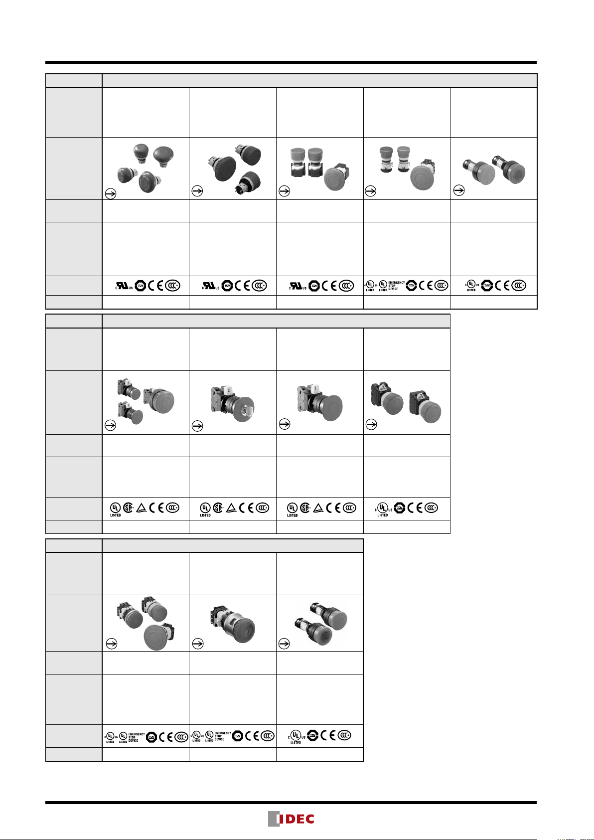
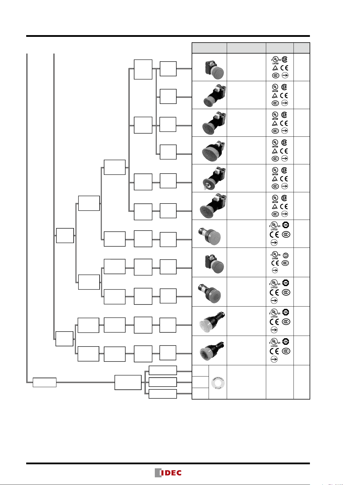
Emergency Stop Switches (Selection Guide)
Series Emergency Stop Switch
Name
Shape
ø16mm X6 Series
Pushlock Pull /
Turn Reset
(Unibody)
ø16mm XA Series
Pushlock Pull /
Turn Reset
(Unibody)
ø16mm XA Series
Pushlock Pull /
Turn Reset (with
Removable Contact
Block)
ø22mm XW Series
Pushlock Pull /
Turn Reset
ø22mm HW Series
Pushlock Turn Reset
(Unibody)
(Plastic/Flush Bezel)
Safety
Category
Applicable
Standards
Mark
Page 8 13 15 21 32
Series Emergency Stop Switch
Name
Shape
Safety
Category
Applicable
Standards
4 4 4 4 4
EN60947-5-5
UL508
CSA C22.2 No.14
GB14048.5
ø22mm HW Series
Pushlock Turn Reset
(with Removable
Contact Block)
4 4 4 4
EN60947-5-5
UL508
CSA C22.2 No.14
GB14048.5
EN60947-5-5
UL508
CSA C22.2 No.14
GB14048.5
ø22mm HW Series
Pushlock Key Reset
EN60947-5-5
UL508
CSA C22.2 No.14
GB14048.5
EN60947-5-5
UL508
UL991
NFPA79
CSA C22.2 No.14
GB14048.5
ø22mm HW Series
Push-Pull
EN60947-5-5
UL508
CSA C22.2 No.14
GB14048.5
EN60947-5-5
UL508
UL991
NFPA79
CSA C22.2 No.14
GB14048.5
ø22mm YW Series
Pushlock Pull /
Turn Reset
EN60947-5-5
UL508
CSA C22.2 No.14
GB14048.5
EN60947-5-5
UL508
CSA C22.2 No.14
GB14048.5
Mark
Page 34 35 35 40
Series Emergency Stop Switch
Name
Shape
Safety
Category
Applicable
Standards
Mark
Page
ø30mm XN Series
Pushlock Pull /
Turn Reset
(Plastic/Flush Bezel)
4 4 4
EN60947-5-5
UL508
UL991
NFPA79
CSA C22.2 No.14
GB14048.5
48
ø30mm XN Series
Pushlock Turn Reset
(Padlockable)
EN60947-5-5
UL508
UL991
NFPA79
CSA C22.2 No.14
GB14048.5
50 55
ø30mm HN Series
Pushlock Turn Reset
(Unibody)
EN60947-5-5
UL508
CSA C22.2 No.14
GB14048.5
2

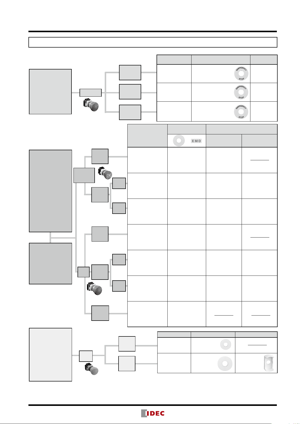
Emergency Stop Switches (Selection Guide)
Series SEMI Emergency Off (EMO) Switch
Name
Shape
ø16mm XA Series
EMO Switch
Pushlock Pull /
Turn Reset
ø22mm XW Series
EMO Switch
Pushlock Pull /
Turn Reset
ø22 HW Series
EMO Switch
Pushlock Turn Reset
Switch Guard for
ø16mm XA Series
ø22mm HW/XW
Series
Safety
Category
Applicable
Standards
Mark —
Page 58 58 58 60
Series Stop Switch
Name
Shape
Safety
Category
Applicable
Standards
4 4 4 —
EN60947-5-5
UL508
CSA C22.2 No.14
GB14048.5
ø16mm XA Series
Pushlock Pull /
Turn Reset
(with Removable
Contact Block)
EN60947-5-1
UL508
CSA C22.2 No.14
GB14048.5
EN60947-5-5
UL508
CSA C22.2 No.14
GB14048.5
ø16mm XA Series
Pushlock Pull /
Turn Reset
(Unibody)
EN60947-5-1
UL508
CSA C22.2 No.14
GB14048.5
EN60947-5-5
UL508
CSA C22.2 No.14
GB14048.5
ø22 XW Series
Pushlock Pull /
Turn Reset
—
EN60947-5-1
UL508
CSA C22.2 No.14
GB14048.5
SEMI S2 0706
ø22 HW Series
Pushlock Turn Reset
Pushlock Pull
UL508
CSA C22.2 No.14
EN60947-5-5
GB14048.5
White Switch Guard
for ø22mm HW/XW
Series
—
Mark —
Page 62 62 63 63 64
3
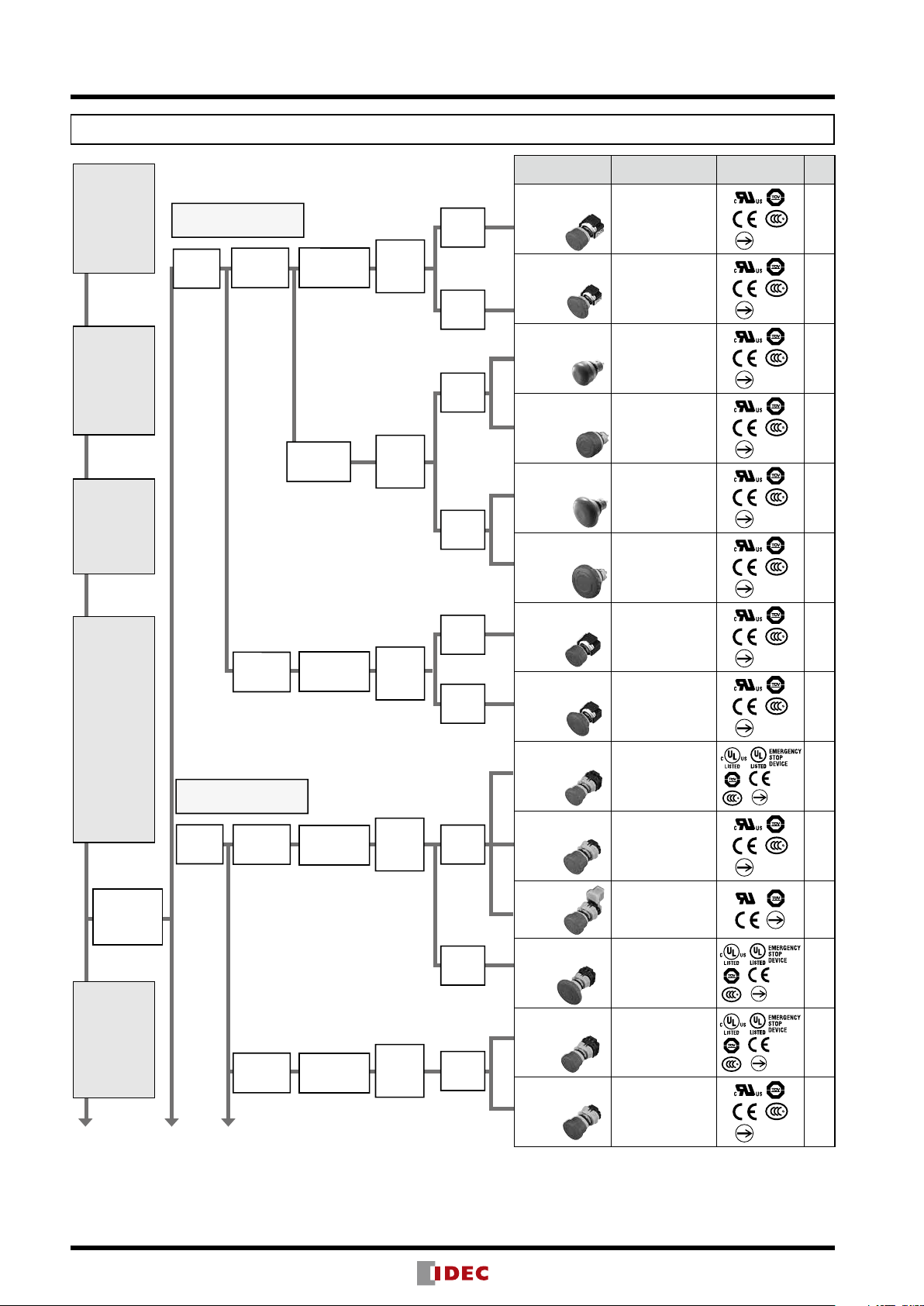
Emergency Stop Switches Selection Diagram
ISO / IEC Standards and Emergency Stop Switches
ISO 13850
4.4.1
mushroom-type
push-buttons
ISO 13850
4.4.4
The command
shall be
maintained
by engagement
(latching-in)
of the actuating
means.
ISO 13850
4.4.4
The actuator of
the emergency
stop device
shall be colored
red.
IEC 60947-5-5
5. Electrical
requirements
5.2 All normally
closed contact
elements of an
emergency stop
device shall
have a direct
opening action
(positive
opening action,
according to
annex K of IEC
60947-5-1.
Emergency
Stop Switch
Reverse Energy Structure
Safe Break Action
ø16mm
Mount
Hole
Reverse Energy Structure
Safe Break Action
ø22mm
Mount
Hole
Non
illuminated
Illuminated
Non
illuminated
(no safe break
action)
Detachable
Contact Block
Unibody
Detachable
Contact Block
Detachable
Contact Block
Pushlock
Pull or
Turn
Reset
Pushlock
Pull or
Turn
Reset
Pushlock
Pull or
Turn
Reset
Pushlock
Pull or
Turn
Reset
ø29mm
Button
ø40mm
Button
ø29mm
Button
ø40mm
Button
ø29mm
Button
ø40mm
Button
ø40mm
Button
Model
XA1E-BV3
(Solder, PC Board
Terminal)
XA1E-BV4
(Solder, PC Board
Terminal)
AB6E-3BV
(Solder Terminal)
XA1E-BV3U
(Solder, Solder/
Tab #110
Terminal)
AB6E-4BV
(Solder Terminal)
XA1E-BV4U
(Solder, Solder/
Tab #110
Terminal)
XA1E-LV3
(Solder, PC Board
Terminal)
XA1E-LV4
(Solder, PC Board
Terminal)
XW1E-BV4
(Screw Terminal)
XW1E-BV4
(Solder, PC Board
Terminal)
XW1E-BV4
(Connector)
Applicable
Standards
EN60947-5-5
UL508/UL991
NFPA79
CSA C22.2 No.14
GB14048.5
EN60947-5-5
UL508/UL991
NFPA79
CSA C22.2 No.14
GB14048.5
EN60947-5-5
UL508
CSA C22.2 No.14
GB14048.5
EN60947-5-5
UL508
CSA C22.2 No.14
GB14048.5
EN60947-5-5
UL508
CSA C22.2 No.14
GB14048.5
EN60947-5-5
UL508
CSA C22.2 No.14
GB14048.5
EN60947-5-5
UL508/UL991
NFPA79
CSA C22.2 No.14
GB14048.5
EN60947-5-5
UL508/UL991
NFPA79
CSA C22.2 No.14
GB14048.5
EN60947-5-5
UL508/UL991
NFPA79
CSA C22.2 No.14
GB14048.5
EN60947-5-5
UL508/UL991
NFPA79
CSA C22.2 No.14
GB14048.5
EN60947-5-5
UL508
Mark
Page
16
16
9
14
9
14
16
16
22
22
22
ISO 13850
4.4.6
As far as a
background
exists behind
the actuator
and as far as
is practicable, it
shall be colored
yellow.
Continued on Next Page
4
Illuminated
Detachable
Contact Block
Pushlock
Pull or
Turn
Reset
ø60mm
Button
ø40mm
Button
XW1E-BV5
(Screw Terminal)
XW1E-LV4
(Screw Terminal)
XW1E-LV4
(Solder, PC Board
Terminal)
EN60947-5-5
UL508/UL991
NFPA79
CSA C22.2 No.14
GB14048.5
EN60947-5-5
UL508/UL991
NFPA79
CSA C22.2 No.14
GB14048.5
EN60947-5-5
UL508/UL991
NFPA79
CSA C22.2 No.14
GB14048.5
22
23
23
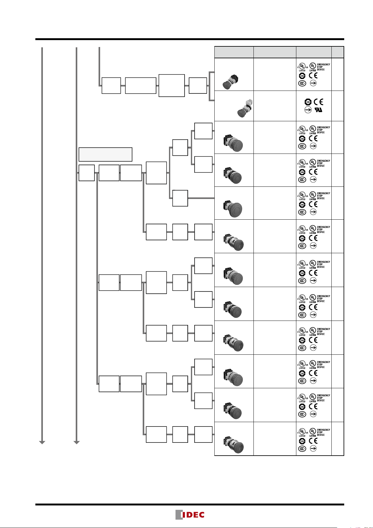
Emergency Stop Switches Selection Diagram
Continued on Next Page
Push-ON
Reverse Energy Structure
Safe Break Action
ø30mm
Mount
Hole
Non
illuminated
Illuminated
Push-ON
Detachable
Contact
Detachable
Contact
Detachable
Contact
Detachable
Contact
Block
Block
Block
Block
Pushlock
Pull or
Turn
Reset
Pushlock
Turn
Reset
Pushlock
Pull or
Turn
Reset
Pushlock
Turn
Reset
Pushlock
Pull or
Turn
Reset
Pushlock
Turn
Reset
Pushlock
Pull or
Turn Reset
ø40mm
Button
ø60mm
Button
ø44mm
Button
ø40mm
Button
ø44mm
Button
ø40mm
Button
ø44mm
Button
ø40mm
Button
Plastic
Bezel
Flush
Bezel
Padlockable
Plastic
Bezel
Flush
Bezel
Padlockable
Plastic
Bezel
Flush
Bezel
Padlockable
Model
XW1E-TV4
(Screw Terminal)
XW1E-TV4
(Connector)
XN1E-BV4
(Plastic Bezel)
XN5E-BV4
(Flush Bezel)
XN1E-BV5
(Plastic Bezel)
XN4E-BL4
(Padlockable)
XN1E-LV4
(Plastic Bezel)
XN5E-LV4
(Flush Bezel)
XN4E-LL4
(Padlockable)
XN1E-TV4
(Plastic Bezel)
XN5E-TV4
(Flush Bezel)
XN4E-TL4
(Padlockable)
Applicable
Standards
EN60947-5-5
UL508/UL991
NFPA79
CSA C22.2
No.14
GB14048.5
EN60947-5-5
UL508
EN60947-5-5
UL508/UL991
NFPA79
CSA C22.2
No.14
GB14048.5
EN60947-5-5
UL508/UL991
NFPA79
CSA C22.2
No.14
GB14048.5
EN60947-5-5
UL508/UL991
NFPA79
CSA C22.2
No.14
GB14048.5
EN60947-5-5
UL508/UL991
NFPA79
CSA C22.2
No.14
GB14048.5
EN60947-5-5
UL508/UL991
NFPA79
CSA C22.2
No.14
GB14048.5
EN60947-5-5
UL508/UL991
NFPA79
CSA C22.2
No.14
GB14048.5
EN60947-5-5
UL508/UL991
NFPA79
CSA C22.2
No.14
GB14048.5
EN60947-5-5
UL508/UL991
NFPA79
CSA C22.2
No.14
GB14048.5
EN60947-5-5
UL508/UL991
NFPA79
CSA C22.2
No.14
GB14048.5
EN60947-5-5
UL508/UL991
NFPA79
CSA C22.2
No.14
GB14048.5
Mark
Page
23
23
48
49
48
50
48
49
50
48
49
50
5
Emergency Stop Switches Selection Diagram
Accessories
ø22mm
Mount
Hole
ø30mm
Mount
Hole
Non
illuminated
Illuminated
Non
illuminated
Illuminated
Detachable
Contact
Block
Unibody
Detachable
Contact
Block
Unibody
Unibody
Unibody
Emergency
Stop
Nameplate
Pushlock
Pull or
Turn
Reset
Pushlock
Turn
Reset
Pushlock
Key
Reset
Pushlock
Pull
Reset
Pushlock
Turn
Reset
Pushlock
Turn
Reset
Pushlock
Turn
Reset
Pushlock
Turn
Reset
Pushlock
Turn
Reset
ø40mm
Button
ø29mm
Button
ø40mm
Button
ø60mm
Button
ø40mm
Button
ø40mm
Button
ø40mm
Button
ø40mm
Button
ø40mm
Button
ø40mm
Button
ø40mm
Button
ø16mm
Mount Hole
ø22mm
Mount Hole
ø30mm
Mount Hole
Model
YW1B-V4
HW1B-V3
HW1B-V4
HW1B-V5
HW1B-X4
HW1B-Y2
HW1E-BV4
YW1L-V4
HW1E-LV4
HN1E-BV4
HN1E-LV4
HAAV
HWAV
HNAV
Applicable
Standards
EN60947-5-5
UL508
CSA C22.2
No.14
GB14048.5
EN60947-5-5
UL508
CSA C22.2
No.14
GB14048.5
EN60947-5-5
UL508
CSA C22.2
No.14
GB14048.5
EN60947-5-5
UL508
CSA C22.2
No.14
GB14048.5
EN60947-5-5
UL508
CSA C22.2
No.14
GB14048.5
EN60947-5-5
UL508
CSA C22.2
No.14
GB14048.5
EN60947-5-5
UL508
CSA C22.2
No.14
GB14048.5
EN60947-5-5
UL508
CSA C22.2
No.14
GB14048.5
EN60947-5-5
UL508
CSA C22.2
No.14
GB14048.5
EN60947-5-5
UL508
CSA C22.2
No.14
GB14048.5
EN60947-5-5
UL508
CSA C22.2
No.14
GB14048.5
IEC 60947-5-5
IEC 60204-1
Mark Page
41
34
34
34
35
35
32
41
32
55
55
11
—
28
53
6
SEMI EMO Switch Guards
Switch and Background Color Selection Chart (IEC/SEMI/SEMATECH)
Emergency Stop
IEC 60947-5-5
IEC 60204-1
ISO 13850
•Red colored
•Mushroom
•Yellow background
•Shall be positioned
for easy access
Emergency Off
(EMO)
SEMATECH Application Guide for SEMI
S2-93
Red and mushroom
shaped button
•Yellow background
•EMO or Emergency
Off labeled
When installing a
guard
•Guard diameter
ø75mm minimum
•Button recessed from
the guard no more
than 3mm
Emergency Off
(EMO)
SEMI S2-0706
•Red and mushroom
shaped button
•Yellow background
•EMO or Emergency
Off labeled
Red button
Red button
(EMO
marking)
Red
button
ø16mm
mounting hole
ø22mm
mounting hole
ø16mm
mounting hole
ø22mm
mounting hole
Yellow
guard
White
guard
Yellow
guard
White
guard
Switch Applicable Nameplate (Note 1)
ø16mm
mounting
hole
ø22mm
mounting
hole
ø30mm
mounting
hole
XA1E
HA1E
HA1B-V
XW1E
HW1E
HW1B-V, HW1B-X
HW1B-Y
XN1E
XN4E
XN5E
HN1E
HAAV-0, HAAV-27
HAAV4-0
HAAV4-27
HWAV-0-Y, HWAV-27-Y
HWAV5-0
HWAV5-27
HWAV5F-27
HNAV-0
HNAV-27
Applicable Nameplate
(Note 1) / EMO label
Switch
SEMI SEMATECH
XA1E-BV4∗∗RH-EMO HAAV4-0 XA9Z-KG1 (Note 2)
HW9Z-KG1 (Note 2)
XW1E-BV4∗∗RH-EMO
HW1B-V4∗∗R-EMO
XW1E-BV4∗∗RH-EMO
HW1B-V4∗∗R-EMO
XA1E
HA1E
HA1B-V
XW1E
HW1E
HW1B-V (Note 4)
HW1B-X
HW1B-Y
XW1E
HW1E
HW1B-V (Note 4)
HW1B-X
HW1B-Y
HWAV-0-Y
HWAV-0-Y HW9Z-KG5-W HW9Z-KG5-W
HAAV-0, HAAV4-0
in combination with
HW9Z-EMO-NPP
HWAV-74-Y,
HWAV-0-Y
in combination with
HW9Z-EMO-NPP
HWAV-74-Y,
HWAV-0-Y
in combination with
HW9Z-EMO-NPP
HW9Z-KG2 (Note 2)
HW9Z-KG3 (Note 2)
HW9Z-KG4 (Note 2)
HW9Z-KG5
XA9Z-KG1 (Note 2)
HW9Z-KG1 (Note 2)
HW9Z-KG2 (Note 2)
HW9Z-KG3 (Note 2)
HW9Z-KG4 (Note 2)
HW9Z-KG5 (Note 3)
HW9Z-KG5-W
(Note 3)
Applicable
Switch Guard
N/A
N/A
N/A
Applicable Switch Guard
HW9Z-KG2 (Note 2)
HW9Z-KG4 (Note 2)
HW9Z-KG5
HW9Z-KG2 (Note 2)
HW9Z-KG4 (Note 2)
HW9Z-KG5 (Note 3)
HW9Z-KG5-W
(Note 3)
Local/Partial
Shut Down
SEMI S26-0308
•Should not use the
combination of red
button with yellow
background
•Should not be labeled as "EMO" or
"Emergency Off," or
the equivalent.
Note: Stop switch (yellow button) should not be labeled as
“EMS” or “Emergency Stop.”
Yellow
Button
ø30mm
mounting
hole
XN1E
XN4E
XN5E
HN1E
ø16mm
mounting hole
ø22mm
mounting hole
HNAV-0
in combination with
HW9Z-EMO-NPP
Switch Applicable Nameplate Applicable Switch Guard
XA1E-BV
HA1E-V2S∗Y
XW1E-BV4∗∗Y
HW1B-V
HW1B-Y2∗∗Y
Note 1: Marking plate legend
Note 2: Cannot be used with a nameplate.
Note 3: Cannot be used with HWAV5-∗.
Note 4: HW1B-V5 switch cannot be used with a switch guard.
Y
Y
HAAV-0-W
HAAV4-0-W
HWAV-0-W
HWAV5-0-W
HW9Z-KG4-W
(Note 2)
HW9Z-KG5-W
(Note 3)
∗∗∗
∗∗∗
-0 (blank), -27 (EMERGENCY STOP), -74 (EMERGENCY OFF)
7

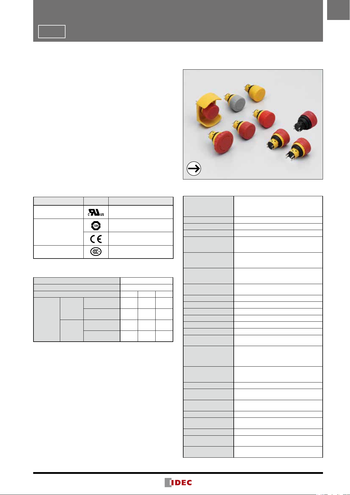
ø16
X6 Series Emergency Stop Switches (Unibody)
Third-generation emergency stop switch with Reverse Energy Structure
Smallest in its class
• Two button sizes—ø30mm and ø40mm
• Two button colors—red for emergency stop and yellow for
stop switch
• Two ways of resetting —pulling and turning.
• Solder/tab terminal #110 makes for easy connections.
• UL, c-UL recognized, EN compliant.
• Safety lock mechanism (IEC 60947-5-5; 6.2)
• Direct opening action (IEC 60947-5-5; 5.2, IEC 60947-5-1,
Annex K)
• IP65 degree of protection (IEC 60529)
Standards
Standard Mark
UL508
CSA C22.2 No.14
EN60947-5-1
EN60947-5-5 (Note)
GB14048.5
• Stop switch (yellow button) is EN60947-5-1
Approval Organization/
File No.
UL/c-UL File No.E68961
TÜV SÜD
European Commission's Low
Voltage Directive
CCC No. 2012010305525957
(Stop switch: CCC No.
2012010305525958)
Contact Ratings
Rated Insulation Voltage (Ui) 250V
Rated Thermal Current (Ith) 5A
Rated Operating Voltage (Ue) 30V 125V 250V
Resistive Load
AC
50/60 Hz
rent (Note)
DC
Main Contacts
Rated Operating Cur-
• Minimum applicable load: 5V AC/DC, 1 mA (reference value)
(May vary depending on the operating conditions and load)
• Operational current represents the classication by making and
breaking currents (IEC 60947-5-1).
Note:
TÜV/CCC rating: AC-15 0.75A/250V, DC-13 1A/30V
UL rating: Standard Duty AC 0.75A/250V
Standard Duty DC 1A/30V
(AC-12)
Inductive Load
(AC-15)
Resistive Load
(DC-12)
Inductive Load
(DC-13)
– 5A 3A
– 1.5A 0.75A
2A 0.4A 0.2A
1A 0.22A 0.1A
Specifications
IEC 60947-5-1, EN 60947-5-1
Applicable Standards
Operating Temperature –25 to +60°C (no freezing)
Operating Humidity 45 to 85% RH (no condensation)
Storage Temperature –45 to +80°C (no freezing)
Operating Force
Minimum Force
Required for Direct
Opening Action
Minimum Operator
Stroke Required for
Direct Opening Action
Maximum Operator
Stroke
Contact Resistance 50 mΩ maximum (initial value)
Insulation Resistance 100 MΩ minimum (500V DC megger)
Overvoltage Category II
Impulse Withstand
Voltage
Pollution Degree 3
Operation Frequency 900 operations/hour
Shock Resistance
Vibration Resistance
Mechanical Life 100,000 operations minimum
Electrical Life 100,000 operations minimum
Degree of Protection IP65 (IEC 60529)
Short-circuit Protection
Conditional Shortcircuit Current
Terminal Style Solder terminal, Solder/tab terminal #110
Recommended Tight-
ening Torque for Locking Ring
Applicable Wire Size 1.25 mm
Terminal Soldering
Condition
Weight (approx.)
Note: Except for stop switch (yellow button)
IEC 60947-5-5 (Note), EN 60947-5-5 (Note)
JIS C8201-5-1, JIS C8201-5-5, UL508
CSA C22.2 No.14, GB14048.5
Push to lock: 10.5N
Pull to reset: 8.8N
Turn to reset: 0.17 N·m
40N
4.5 mm
4.5 mm
2.5 kV
Operation extremes: 150 m/s
Damage limits: 1000 m/s
Operation extremes: 10 to 500 Hz
amplitude 0.35 mm, acceleration 50 m/s
Damage limits: 10 to 500 Hz,
amplitude 0.35 mm, acceleration 50 m/s
250V/10A fuse
(Type aM IEC 60269-1/IEC 60269-2)
1000A
0.88 N·m
2
maximum (AWG16 maximum)
310 to 350°C, within 3 seconds
ø30mm button: 13g
ø40mm button: 16g
2
2
2
2
8

X6
X6 Series Emergency Stop Switches (Unibody)
Unmarked
Pushlock Pull/Turn Reset Switch
Shape Main Contact (NC)
ø30mm Mushroom
1NC AB6E-3BV01PRH AB6E-3BV01PTRH
2NC AB6E-3BV02PRH AB6E-3BV02PTRH
ø40mm Mushroom
1NC AB6E-4BV01PRH AB6E-4BV01PTRH
2NC AB6E-4BV02PRH AB6E-4BV02PTRH
• Pushlock pull/turn reset switches are locked when pressed, and reset when pulled or turned clockwise.
Solder Terminal Solder/tab Terminal #110
Arrow Marked
Part No.
ø16
Package quantity: 1
Pushlock Pull/Turn Reset Switch
Shape Main Contact (NC)
ø30mm Mushroom
1NC AB6E-3BV01PRM AB6E-3BV01PTRM
2NC AB6E-3BV02PRM AB6E-3BV02PTRM
ø40mm Mushroom
1NC AB6E-4BV01PRM AB6E-4BV01PTRM
2NC AB6E-4BV02PRM AB6E-4BV02PTRM
• Pushlock pull/turn reset switches are locked when pressed, and reset when pulled or turned clockwise.
Solder Terminal Solder/tab Terminal #110
Part No.
Stop Switch
Unmarked, Yellow Button, Pushlock Pull/Turn Reset Switch
Shape Operator
ø30mm Mushroom
ø30mm but-
ton
Main Contact
(NC)
1NC AB6E-3BV01PY AB6E-3BV01PTY
2NC AB6E-3BV02PY AB6E-3BV02PTY
Solder Terminal Solder/tab Terminal #110
Package quantity: 1
Package quantity: 1
Part No.
ø40mm but-
ton
• Pushlock pull/turn reset switches are locked when pressed, and reset when pulled or turned clockwise.
• Do not use the stop switch as an emergency stop switch.
1NC AB6E-4BV01PY AB6E-4BV01PTY
2NC AB6E-4BV02PY AB6E-4BV02PTY
9
ø16
+0.2
Y
ø40mm Button
Panel thickness 0.8 to 4.5
Solder/tab terminal #110
(Depth behind the panel: 23.9 mm)
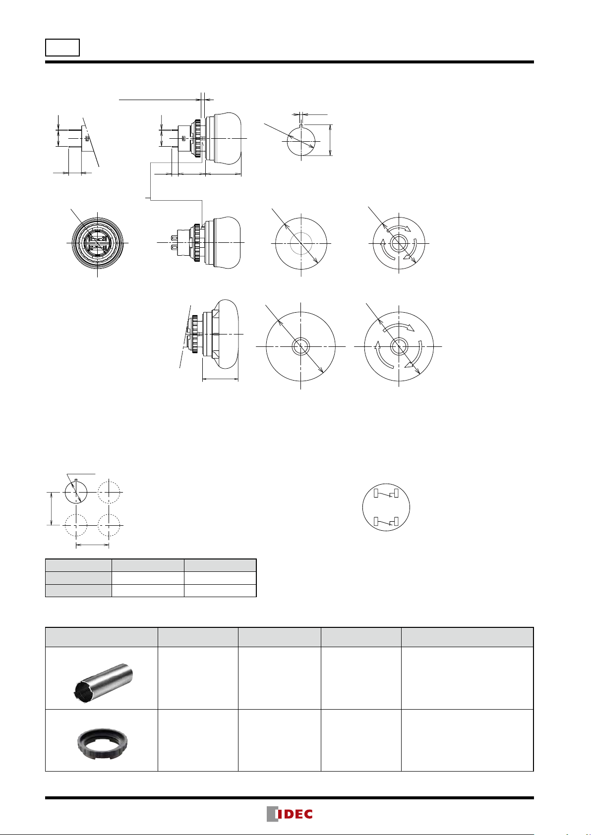
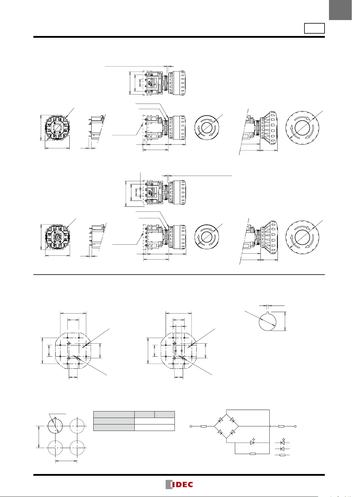
X6 Series Emergency Stop Switches (Unibody)
Dimensions
0.59.2
+0.2
0
+0.2
0
1.7
+0.2
0
17.9
0.59.2
ø16.2
8.0
Anti-rotation projection
ø15.8
Mounting Hole Layout
ø16.2
0
X
ø30 mm Button 40 mm min. 40mm min.
ø40 mm Button 50 mm min. 50mm min.
Accessories
Shape Material Part No. Package Quantity Remarks
Locking Ring Wrench
3.6
15.9
Solder terminal
(Depth behind the panel: 19.5 mm)
The values shown on the left are the
minimum dimensions for mounting
with other ø16 mm pushbuttons. For
other control units of different sizes and
styles, determine the values according to
dimensions, operation, and wiring.
20.6
20.6
X Y
Metal
(nickel-plated brass)
MT-001 1
Mounting Hole Layout
ø30.0
Unmarked
ø40.0
Unmarked
ø30.0
ø30mm Button
Arrow Marked
ø40.0
Arrow Marked
Terminal Arrangement
(Bottom View)
TOP
2
1
1
2
1NC type: Terminals located near
the TOP marking
• Used to tighten the locking ring
when installing the X6 switch onto
a panel.
• Recommended tightening torque:
0.88 N·m maximum
All dimensions in mm.
Locking Ring
Plastic XA9Z-LNPN10 10
• Black
10
t
ø16
1.7 0.3
Projection
Projection
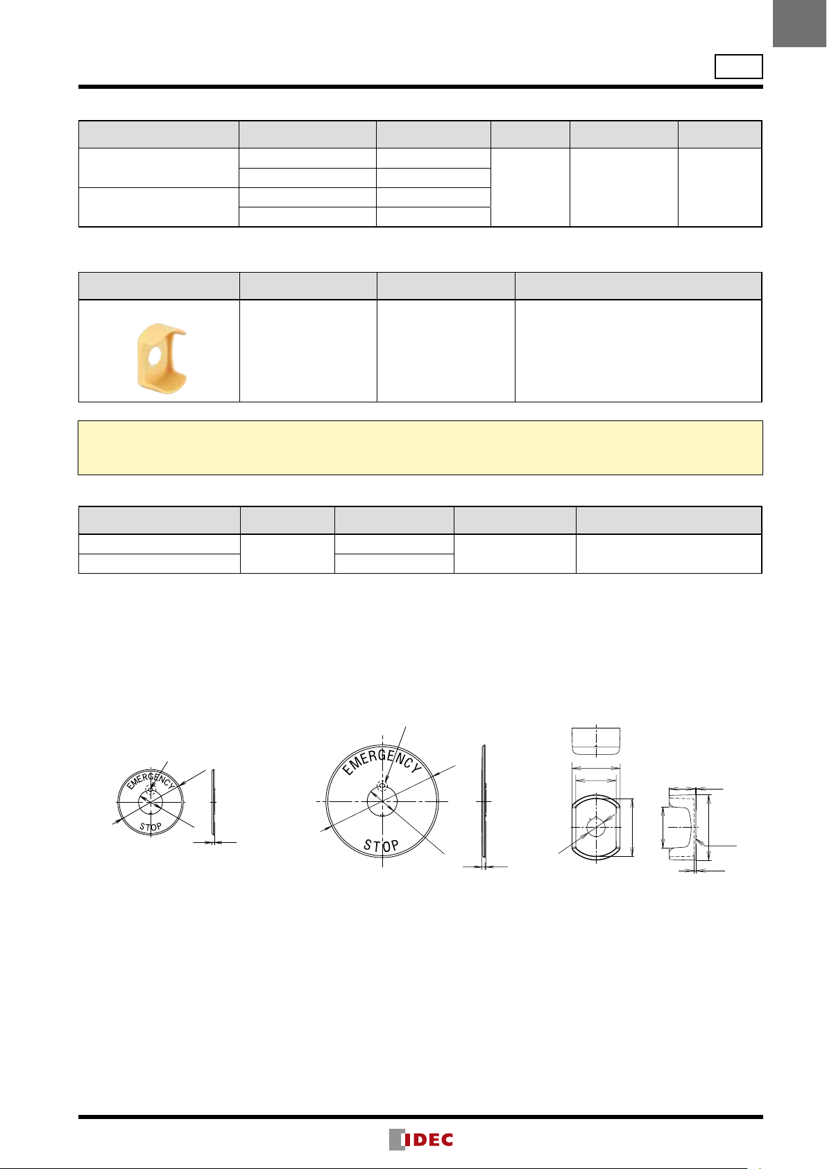
X6
X6 Series Emergency Stop Switches (Unibody)
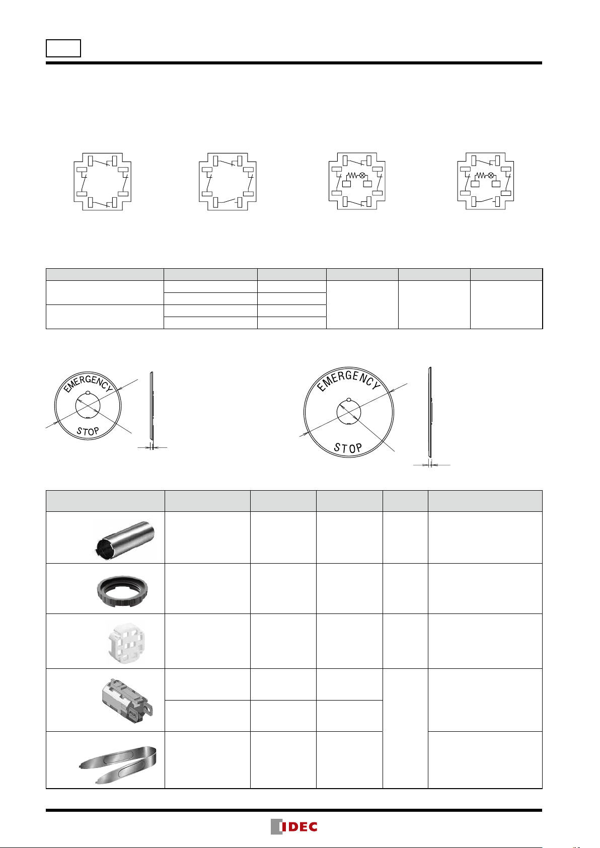
Nameplate (for emergency stop switch)
Description Legend Part No. Material Background Color Legend Color
For ø30mm Button
For ø40mm Button
• Cannot be used with switch guard.
Blank HAAV-0
EMERGENCY STOP HAAV-27
Blank HAAV4-0
EMERGENCY STOP HAAV4-27
Polyamide Yellow Black
SEMI S2 Compliant Switch Guard
Shape Material Part No. Remarks
Switch Guard
• IP65 degree of protection
Polyamide (PA6) XA9Z-KG1
Note:
Switch guards have been designed for applications in semiconductor manufacturing equipment only. Do not use the switch guards with emergency stop
switches which are installed on other machines such as machine tools or food processing machines. Machinery Directive of the European Commission and
IEC 60204-1 require that emergency stop switches be installed in a readily accessible area, and the usage of switch guards is not permitted.
• Color: yellow (Munsell 2.5Y8/10 or equivalent)
• Cannot be used with nameplate.
Package quantity: 1
Package quantity: 1
ø16
White Nameplate (for stop switch)
Description Legend Part No. Material Background Color
For ø30mm Button
For ø40mm Button HAAV4-0-W
Blank
HAAV-0-W
Polyamide White (Munsell N9.5)
Dimensions
Nameplate for ø30mm Button
•
HAAV-∗
ø43.5
ø16
• Remove the projection from the nameplate using pliers, otherwise the switch cannot be installed.
• Panel thickness when using a nameplate: 0.5 to 3 mm
Nameplate for ø40mm Button
•
HAAV4-∗
ø60
ø16
0.51.7
Package quantity: 1
Switch Guard
•
XA9Z-KG1
42
35
36
ø50
• Panel thickness when using a nameplate:
0.5 to 3 mm
23.1
(0.2)
ø57
Gaske
(1.7)
11
ø16
Projection
Rubber Gaske
Locking Ring
Operator
X6 Series Emergency Stop Switches (Unibody)
Safety Precautions
•Turn off power to the X6 series units before installation, removal,
wiring, maintenance, and inspection. Failure to turn power off
may cause electrical shocks or re hazard.
Instructions
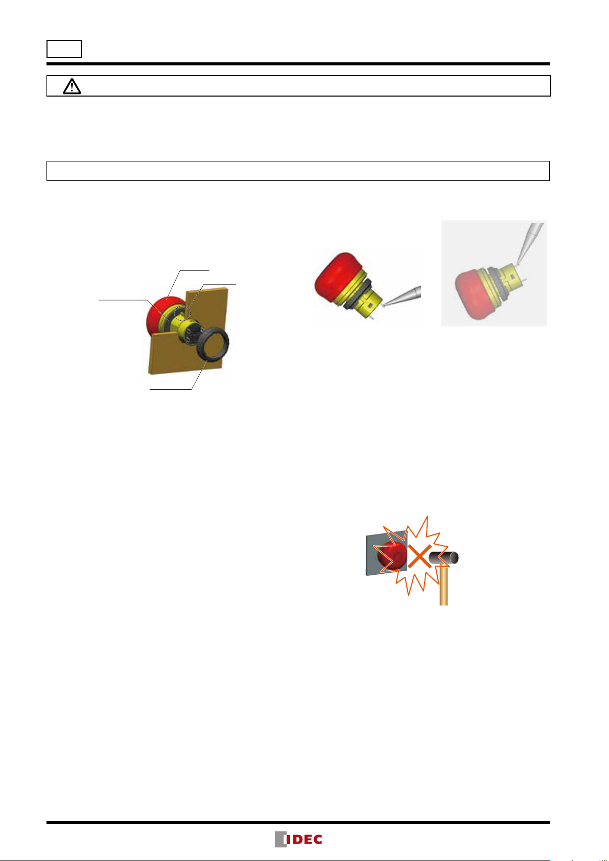
Panel Mounting
Remove the locking ring from the operator and check that
the rubber gasket is in place. Insert the operator from panel
front into the panel hole. Face the side with the projection
upward, and tighten the locking ring using the locking ring
wrench MT-001.
t
•For wiring, use wires of proper size to meet the voltage
and current requirements and solder properly. Improper
soldering may cause overheating and create re hazards.
3. Use a non-corrosive rosin ux. To prevent the ux from
entering the switch while soldering, face the terminals
downward.
Correct
4. Because the terminal spacing is narrow, use protective
tubes or heat shrinkable tubes to avoid burning the wire
sheath or short circuit.
5. Apply force on the terminals in the vertical direction to the
panel only, otherwise the terminals will be damaged.
Incorrect
Notes for Panel Mounting
Using the locking ring wrench MT-001, tighten the locking
ring to a torque of 0.88 N·m. Do not use pliers. Do not apply
excessive force, otherwise the locking ring will become
damaged.
Wiring
1. Applicable wire size is 1.25 mm2 maximum.
2. Solder the terminals using a soldering iron at 310 to 350°C
for 3 seconds maximum. Do not use ow or dip soldering.
SnAgCu type lead-free solder is recommended. Make
sure that the soldering iron touches the terminals only, not
plastic parts. Do not apply external force such as bending
the terminals or applying tensile force on the wires.
Contact Bounce
When the button is reset by pulling or turning, the NC
contacts will bounce. When designing a control circuit, take
the contact bounce time into consideration (reference value:
20 ms).
Handling
Do not expose the switch to excessive shock and vibrations,
otherwise the switch may be deformed or damaged, causing
malfunction or operation failure.
12
ø16
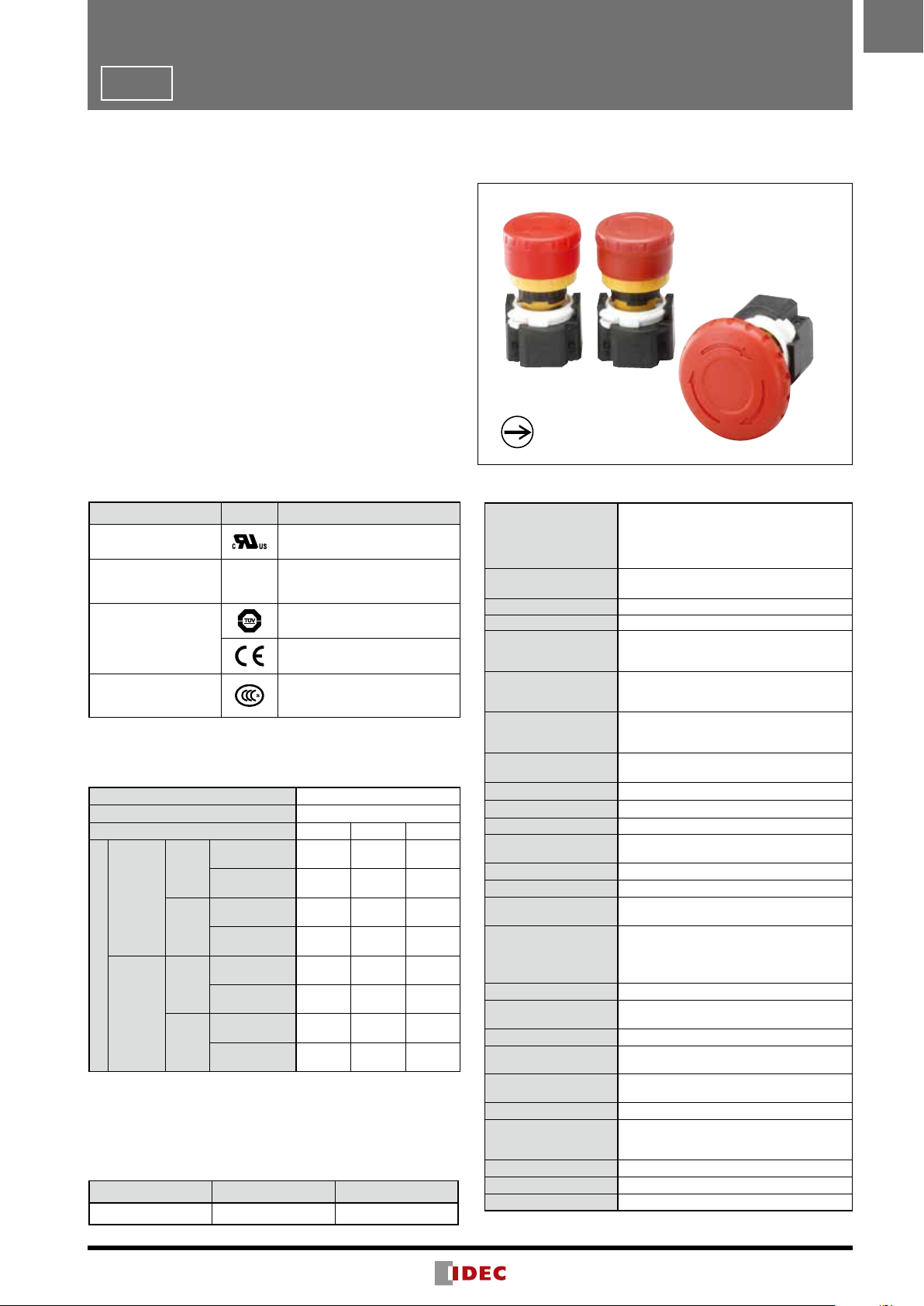
XA Series Emergency Stop Switches (Unibody)
Small, unibody emergency stop switches suitable for equipment with small mounting space.
Requires only ø16mm × 19.5mm for installation.
•ø29mm and ø40mm mushroom operators
•Degree of protection IP65 and IP40 (IEC 60529)
•Dark red (Munsell 5R4/12) and bright red (Munsell
7.5R4.5/14) colors for operators of emergency stop
switches, and yellow/gray for stop switch operators.
•Gold-plated crossbar contacts
•Push-to-lock, pull or turn-to-reset operator
•UL, c-UL recognized. EN compliant.
•Safety lock mechanism (IEC 60947-5-5, 6.2)
•Direct opening action mechanism
(IEC 60947-5-5, 5.2, IEC60947-5-1, Annex K)
Solder Terminal
IP65
(body color: yellow)
Solder Terminal
IP40
(body color: black)
Solder/tab #110
XA
Standards
Applicable Standards Mark File No. or Organization
UL508
CSA C22.2 No.14
EN60947-5-1
EN60947-5-5 (note)
GB14048.5
Note: Except for stop switch (yellow and gray button)
UL/c-UL Recognition
File No.E68961
TÜV SÜD
EU Low Voltage Directive
CCC No. 2008010305286343
Contact Ratings
Rated Insulation Voltage (Ui) 250V
Thermal Current (Ith) 5A
Rated Operating Voltage (Ue) 30V 125V 250V
Resistive Load
AC
Rated
Operating
Current
•Minimum applicable load: 5V AC/DC, 1 mA (reference value)
(May vary depending on the operating conditions and load.)
•The rated operating currents are measured at resistive/inductive
loads as specied in IEC 60947-5-1.
50/60Hz
DC
(AC-12)
Inductive Load
(AC-15)
Resistive Load
(DC-12)
Inductive Load
(DC-13)
— 5A 3A
— 3A 1.5A
2A 0.4A 0.2A
1A 0.22A 0.1A
Specifications
IEC 60947-5-1, EN 60947-5-1
Applicable Standards
Operating Temperature −25 to +60°C (no freezing)
Storage Temperature −45 to +80°C (no freezing)
Operating Humidity 45 to 85% RH (no condensation)
Operating Force
Minimum Force
Required for Direct
Opening Action
Minimum Operator
Stroke Required for
Direct Opening Action
Maximum Operator
Stroke
Contact Resistance 50 mΩ maximum (initial value)
Insulation Resistance 100 MΩ minimum (500V DC megger)
Overvoltage Category II
Impulse Withstand Voltage
Pollution Degree 3
Operating Frequency 900 operations/hour
Shock Resistance
Vibration Resistance
Durability
Degree of Protection IP65, IP40 (IEC 60529)
Short-circuit
Protection
Conditional
Short-circuit Current
Terminal Style Solder terminal, Solder/tab #110 terminal
Recommended Tightening
Torque for Locking Ring
Applicable Wire Size 1.25 mm
Terminal Soldering
Condition
Weight (approx.)
Note: Except for stop switches (operator color: yellow and gray)
IEC 60947-5-5 (Note), EN 60947-5-5 (Note)
JIS C8201-5-1, UL508, CSA C22.2 No.14
GB14048.5
Push-to-lock: 10.5N
Pull to reset: 10N
Turn to reset: 0.16 N·m
40N
4.0 mm
4.5 mm
2.5 kV
Operating extremes: 150 m/s
Damage limits: 1000 m/s
Operating extremes: 10 to 500 Hz,
amplitude 0.35mm, acceleration 50 m/s
Damage limits: 10 to 500 Hz,
amplitude 0.35 mm, acceleration 50 m/s
Mechanical: 250,000
Electrical: 100,000
250,000 (24V AC/DC, 100mA)
250V/10A fuse
(Type aM IEC 60269-1/IEC 60269-2)
1000A
0.88 N·m
2
maximum (AWG16 maximum)
310 to 350°C, within 3 seconds
ø29mm mushroom: 14g
ø40mm mushroom: 17g
2
2
2
2
13

ø29 mm Mushroom ø40 mm Mushroom
Solder/
Panel Thickness 0.8 to 4.5
TOP
1NC: Termimals on top
ø16.2
+0.2
Y
ø16
XA Series Emergency Stop Switches (Unibody)
XA Series
Pushlock Pull/Turn Reset (Solder Terminal)
Shape Contact
ø29mm Mushroom
1NC XA1E-BV3U01K
Part No.
IP40 (contact part: black) IP65 (contact part: yellow)
XA1E-BV3U01
Operator Color
Code
2NC XA1E-BV3U02K
ø40mm Mushroom
1NC XA1E-BV4U01K
2NC XA1E-BV4U02K
•Solder/tab #110 terminal is also available. Specify “T” before in the Ordering No.
XA1E-BV3U02KR → XA1E-BV3U02KTR
Dimensions
0.510.2
Tab Terminal #110
(Behind the panel: 23.9)
ø15.8
10.2 0.5
20.6
15.93.615.98.0
Solder Terminal
(Behind the panel: 19.5)
ø16.2
1.7
+0.2
0
Mounting Hole
ø29.0
+0.2
0
0
+0.2
17.9
20.6
XA1E-BV3U02
R: red
RH: bright red
XA1E-BV4U01
XA1E-BV4U02
Terminal Arrangement
(Bottom View)
1
2
21
Mounting Hole Layout
ø40
0
X
•Thevaluesshown
on the left are the
minimum dimensions
for mounting with other
ø16 mm pushbuttons.
For other control units
of different sizes and
styles, determine the
values according to the
dimensions, operation,
and wiring.
14
All dimensions in mm.
X Y
ø29mm Mushroom 40 mm minimum
ø40mm Mushroom 50 mm minimum
ø16
XA Series Emergency Stop Switches (w/Removable Contact Block)
The World’s First ø16 mm, 4-contact Emergency Stop Switch.
Compact size - only 27.9 mm deep behind the panel. Reliable “Safe break action.”
•The depth behind the panel is only 27.9 mm for 1 to 4
con tacts, both on illuminated and non-illuminated.
•IDEC’s original “Safe break action” ensures that the
contacts open when the contact block is detached from
the operator.
•1 to 4NC main contacts and 1NO monitor contact
•Push-to-lock, Pull or Turn-to-reset operator
•Direct opening action mechanism (IEC 60947-5-5, 5.2,
IEC60947-5-1, Annex K)
•Safety lock mechanism (IEC 60947-5-5, 6.2)
•Degree of protection IP65 (IEC 60529)
•Two operator sizes: ø29 and ø40 mm
•Dark red (Munsell 5R4/12) or bright red (Munsell
7.5R4.5/14) colors are available for the operator of nonilluminated emer gency stop switches, and gray for stop
switch operators.
•UL, c-UL recognized. EN compliant
Direct Opening Action
XA
Standards
Applicable Standards Mark File No. or Organization
UL508
CSA C22.2 No. 14
IEC60947-5-5 (Note)
UL991 (Note)
NFPA79 (Note)
EN60947-5-1
EN60947-5-5 (Note)
GB14048.5
Note: Except for stop switches (button color: gray).
UL/c-UL Recognized,
File No. E68961
— UL File No. E305148
TÜV SÜD
EU Low Voltage Directive
CCC No. 2005010305150899
(Stop switch:
CCC No. 2005010305150894)
Contact Ratings
NC main contacts (black) /NO monitor contact (blue)
Rated Insulation Voltage (Ui) 300V (illuminated part: 60V)
Rated Thermal Current (Ith) 5A
Rated Operating Voltage (Ue) 30V 125V 250V
Resistive Load
AC
(AC-12)
50/60
Inductive Load
Hz
DC
AC
50/60
Hz
DC
(AC-15)
Resistive Load
(DC-12)
Inductive Load
(DC-13)
Resistive Load
(AC-12)
Inductive Load
(AC-14)
Resistive Load
(DC-12)
Inductive Load
(DC-13)
Main
Contacts
Monitor
Rated Operating Current
Contacts
•Minimum applicable load: 5V AC/DC, 1 mA (reference value)
(Operating area may vary according to the operating conditions
and load types.)
•The rated operating currents are measured at resistive/inductive
load types specied in IEC 60947-5-1.
– 3A 3A
– 1.5A 1.5A
2A 0.4A 0.2A
1A 0.22A 0.1A
– 1.2A 0.6A
– 0.6A 0.3A
2A 0.4A 0.2A
1A 0.22A 0.1A
Illumination Ratings
Rated Voltage Operating Voltage Rated Current
24V AC/DC 24V AC/DC ±10% 11 mA
Specifications
IEC60947-5-1, EN60947-5-1
Applicable Standards
Operating
Temperature
Storage Temperature –45 to +80°C
Operating Humidity 45 to 85% RH (no condensation)
Operating Force
Minimum Force
Required for Direct
Opening Action
Minimum Operator
Stroke Required for
Direct Opening Action
Maximum Operator
Stroke
Contact Resistance
Insulation Resistance
Overvoltage Category II
Impulse Withstand
Voltage
Pollution Degree 3 (inside LED unit: 2)
Operation Frequency 900 operations/hour
Shock Resistance
Vibration Resistance
Mechanical Life 250,000 operations minimum
Electrical Life
Degree of Protection IP65 (IEC60529)
Short-circuit
Protection
Conditional
Short-circuit Current
Terminal Style Solder terminal, PC board terminal
Recommended
Tightening Torque
for Locking Ring
Connectable Wire 1.25 mm
Soldering Conditions 310 to 350°C, 3 seconds maximum
Weight ø29 mm: 23g, ø40 mm: 28g
Note: Except for stop switches (operator color: gray).
IEC60947-5-5 (Note), EN60947-5-5
(Note), JIS C8201-5-1, UL991 (Note),
NFPA79 (Note), UL508, CSA C22.2
No.14, GB14048.5
–25 to +60°C (no freezing)
Illuminated: –25 to +55°C (no freezing)
Push to lock: 10.5N
Pull to reset: 10N
Turn to reset: 0.16 N·m
60N
4.0 mm
4.5 mm
50 mΩ maximum (initial value)
100 MΩ minimum (500V DC megger)
2.5 kV
Operating extremes: 150 m/s
Damage limits: 1000 m/s
Operating extremes: 10 to 500 Hz,
amplitude 0.35 mm acceleration 50 m/s
Damage limits: 10 to 500 Hz,
amplitude 0.35 mm acceleration 50 m/s
100,000 operations min
250,000 operations min (24V AC/DC, 100 mA)
250V/10A fuse
(Type aM, IEC60269-1/IEC60269-2)
1000A
0.88 N·m
2
maximum (AWG16 maximum)
2
2
2
2
15
ø16
XA Series Emergency Stop Switches (w/Removable Contact Block)
Non-illuminated
Pushlock Pull/Turn Reset (Solder Terminal/PC Board Terminal)
Shape
ø29mm Mushroom
ø40mm Mushroom
•Specify a color code in place of ➀ in the Part No.
•Terminal cover (XA9Z-VL2) is ordered separately.
•For EMO Switches, see page 58.
NC Main
Contact
1NC —
2NC —
3NC —
4NC —
1NC 1NO
2NC 1NO
3NC 1NO
1NC —
2NC —
3NC —
4NC —
1NC 1NO
2NC 1NO
3NC 1NO
NO Monitor
Contact
Illuminated
Pushlock Pull/Turn Reset (Solder Terminal/PC Board Terminal)
Shape
ø29mm Mushroom
ø40mm Mushroom
•Terminal cover (XA9Z-VL2) is ordered separately.
NC Main
Contact
1NC — XA1E-LV301Q4R XA1E-LV301Q4VR
2NC — XA1E-LV302Q4R XA1E-LV302Q4VR
3NC — XA1E-LV303Q4R XA1E-LV303Q4VR
4NC — XA1E-LV304Q4R XA1E-LV304Q4VR
1NC 1NO XA1E-LV311Q4R XA1E-LV311Q4VR
2NC 1NO XA1E-LV312Q4R XA1E-LV312Q4VR
3NC 1NO XA1E-LV313Q4R XA1E-LV313Q4VR
1NC — XA1E-LV401Q4R XA1E-LV401Q4VR
2NC — XA1E-LV402Q4R XA1E-LV402Q4VR
3NC — XA1E-LV403Q4R XA1E-LV403Q4VR
4NC — XA1E-LV404Q4R XA1E-LV404Q4VR
1NC 1NO XA1E-LV411Q4R XA1E-LV411Q4VR
2NC 1NO XA1E-LV412Q4R XA1E-LV412Q4VR
3NC 1NO XA1E-LV413Q4R XA1E-LV413Q4VR
NO Monitor
Contact
Part No.
Solder Terminal PC Board Terminal
XA1E-BV301
XA1E-BV302
XA1E-BV303
XA1E-BV304
XA1E-BV311
XA1E-BV312
XA1E-BV313
XA1E-BV401
XA1E-BV402
XA1E-BV403
XA1E-BV404
XA1E-BV411
XA1E-BV412
XA1E-BV413
Solder Terminal PC Board Terminal
➀
➀
➀
➀
➀
➀
➀
➀
➀
➀
➀
➀
➀
➀
Part No.
XA1E-BV301V
XA1E-BV302V
XA1E-BV303V
XA1E-BV304V
XA1E-BV311V
XA1E-BV312V
XA1E-BV313V
XA1E-BV401V
XA1E-BV402V
XA1E-BV403V
XA1E-BV404V
XA1E-BV411V
XA1E-BV412V
XA1E-BV413V
➀
➀
➀
➀
➀
➀
➀
➀
➀
➀
➀
➀
➀
➀
Operator
Color Code
R: Dark red
RH: Bright
red
Operator
Color
Dark red only
16
Solder Terminal
ø29mm Mushroom
ø40mm Mushroom
PC Board Terminal
3.1
Locking Ring
Rubber Gasket
Mounting Panel Thickness: 0.8 to 3.7
XA9Z-VL2
Terminal Cover
19.8
8.7
2.1
27.2
25.8 20.6
30.4
29.4
30.4
ø29.8
25.8
20.6
30.4
ø40
ø29
ø29mm Mushroom
Solder Terminal
27.2
19.8
8.7
4.5
Mounting Panel Thickness: 0.8 to 3.7
2.1
25.8
20.6
30.4
PC Board Terminal
3.1
29.4
30.4
ø29.8
Locking Ring
Rubber Gasket
XA9Z-VL2
Terminal Cover
25.8
20.6
30.4
ø40mm Mushroom
ø40
ø29
0
+0.2
ø16.2
0
+0.2
1.7
0
+0.2
17.9
8.7
19.8
8.7
19.8
10-ø1.2 holes
6.5
11.2
4.5
3-ø1.7 holes
3-ø1.7 holes
8.7
19.8
8.7
19.8
10-ø1.2 holes
6.5
11.2
ø16.2
+0.2
0
X
Y
X1
Protection diode
Resistor
XA
XA Series Emergency Stop Switches (w/Removable Contact Block)
Dimensions
Non-illuminated
Illuminated
ø16
PC Board Layout (Bottom View) Panel Cut-out
Non-Illuminated Illuminated
Mounting Hole Layout LED Unit Internal Circuit
X Y
R1 R2
LED
R3
ø29mm Mushroom 40 mm minimum
ø40mm Mushroom 50 mm minimum
•The values shown above are the minimum
dimensions for mounting with other ø16
mm pushbuttons. For other control units
of different sizes and styles, determine
the values according to the dimensions,
opera tion, and wiring convenience.
All dimensions in mm.
X2
LED chip
17
12
12
TOP
21
21
LeftRight
TOP
21
21
12
34
LeftRight
NC main contacts (black)
NC main contacts (black):
Terminals 1-2
1NC: Terminals on right
2NC: Terminals on right and left
3NC: Terminals on right, left, and top
Non-illuminated
LeftRight
TOP
21
21
12
12
X1 X2
TOP
LeftRight
21
21
12
34
X1 X2
LEDLED
For ø29mm Operator
ø43.5
ø16
1.70.3
0.5
1.7
ø60
ø16
Ring Wrench
Locking Ring
Terminal Cover
LED Unit
LED Unit Removal Tool
ø16
XA Series Emergency Stop Switches (w/Removable Contact Block)
Terminal Arrangement (Bottom View)
Illuminated
only
With NO monitor contacts (blue)
NC main contacts (black):
Terminals 1-2
NO monitor contacts (blue):
Terminals 3-4
1NC: Terminals on top
2NC: Terminals on right and left
NC main contacts only (black)
NC main contacts(black):
Terminals 1-2
1NC: Terminals on right
2NC: Terminals on right and left
3NC: Terminals on right, left, and top
Nameplates (for ø16 Emergency Stop Switches)
Description Legend Part No. Material Plate Color Legend Color
For ø29mm Operator
For ø40mm Operator
(blank) HAAV-0
EMERGENCY STOP HAAV-27
(blank) HAAV4-0
EMERGENCY STOP HAAV4-27
For ø40mm Operator
•Panel thickness when using
the nameplate: 0.5 to 2 mm
With NO monitor contacts (blue)
NC main contacts (black):
Terminals 1-2
NO monitor contacts (blue):
Terminals 3-4
1NC: Terminals on top
2NC: Terminals on right and left
Polyamide Yellow Black
•Panel thickness when using
the nameplate: 0.5 to 2 mm
Accessories and Replacement Parts
Description & Shape Material Part No. Ordering No.
Package
Quantity
•Used to tighten the locking
Metal
(nickel-plated brass)
MT-001 MT-001 1
ring when installing the XA
emer gency stop switch onto
a panel.
Polyamide XA9Z-LN XA9Z-LNPN10 10 •Black
•White
PBT XA9Z-VL2 XA9Z-VL2PN02 2
•Used for solder terminals.
•Also applicable to the XW
series.
For Solder Terminal XA9Z-LED2R XA9Z-LED2R
•Replacement LED unit for
illumi nated (for XA series
For PC Board
Terminal
XA9Z-LED2VR XA9Z-LED2VR
only).
1
All dimensions in mm.
Remarks
18
Stainless Steel MT-101 MT-101
•Used for removing the LED
unit.
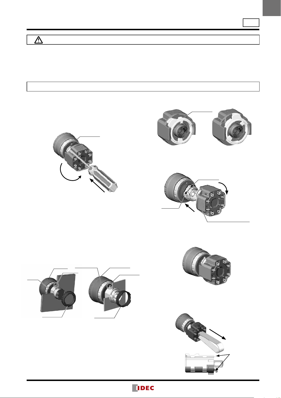
Operator
Removing the Contact Block
First unlock the operator button. While pushing up the
white bayonet ring, using a small screwdriver (width: 2.5 to
3 mm) if necessary, turn the contact block
counterclockwise and pull out.
force when using a screwdriver, otherwise the bayonet
ring may be dam aged.
➁
Notes for Removing the Contact Block
1. When the contact block is removed, the monitor contact
2. While removing the contact block, do not exert excessive
Panel Mounting
Remove the locking ring from the operator and check
that the rubber gasket is in place. Insert the operator from
panel front into the panel hole. Face the side with the antirotation protrusion on the operator upward, and tighten the
locking ring.
Rubber Gasket
Notes for Panel Mounting
To mount the XA emergency stop switches onto a panel,
tighten the locking ring to a tightening torque of 0.88 N·m
maximum using ring wrench MT-001. Do not use pliers. Do
not exert excessive force, otherwise the locking ring may
be damaged.
Installing the Contact Block
Bayonet Ring
Unlocked Locked
marking on the edge of the operator base
con tact block onto the operator and turn the contact block
XA
XA Series Emergency Stop Switches (w/Removable Contact Block)
Safety Precautions
•Turn off power to the XA series emergency stop switch
before starting installation, removal, wiring, maintenance,
and inspection of the relays. Failure to turn power off may
cause electrical shock or re hazard.
•Use the LED unit removal tool when replacing the LED
unit to avoid burn on your hands.
Instructions
Do not exert excessive
Bayonet Ring
•Use wires of the proper size to meet the voltage and
cur rent requirements, and solder the wires correctly. If
solder ing is incomplete, the wire may heat during operation, causing re hazard.
First turn the bayonet ring to the unlocked position.
Align the small ▲
with the TOP marking on the contact block. Press the
ø16
Turn counterclockwise
Push
➀
(NO contact) is closed.
force, otherwise the switch may be damaged.
Gasket
Locking Ring
Projection
Contact BlockUnibody
Operator Unit
Locking Ring
clock wise until the bayonet ring clicks.
▲ marking
Press
➀
TOP marking
➁
TOP marking (contact block)
Notes for Installing the Contact Block
Check that the contact block is securely installed on the
opera tor. When the emergency stop switch is properly
assembled, the bayonet ring is in place as shown below.
Anti-rotation
Protrusion
Removing the LED Unit (Contact Block)
Pull out the LED unit while squeezing the latches on the
LED unit using the LED unit removal tool (MT-101).
Squeeze the
LED unit on the
latches and pull
out.
Tur n
TOP side
Latches
19
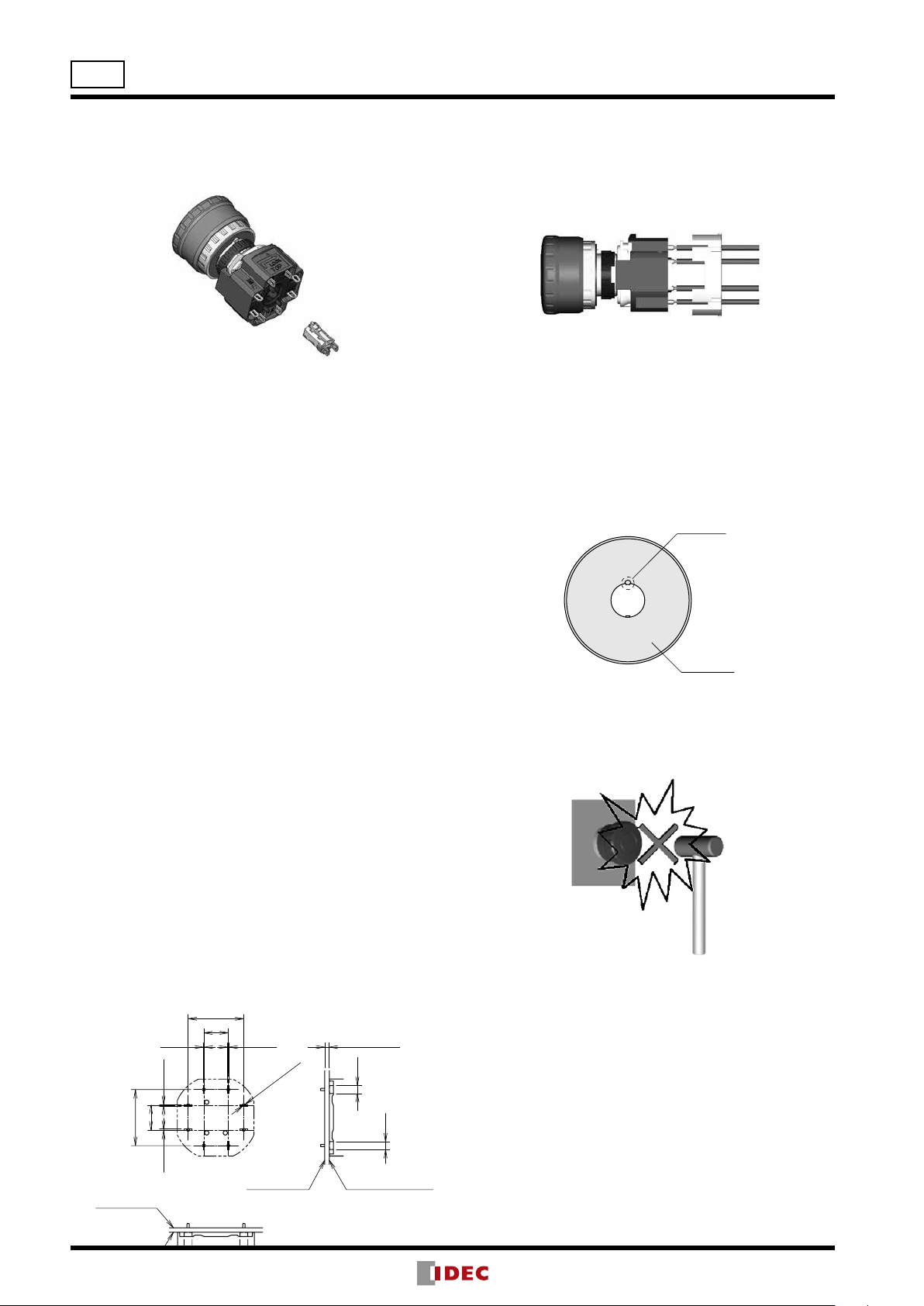
Installing the LED Unit (with Removable
Contact Block)
Align the to of the LED unit with the TOP marking on the
contact block. Push the LED unit into the contact block.
Wiring
1. The applicable wire size is 1.25 mm
2. Solder the terminal at a temperature of 310 to 350°C
3. Use a non-corrosive rosin ux.
4. Because the terminal spacing is narrow, use protective
Solder/Tab Terminal #110
1. Use #110 receptacles for 0.5mm-thick tabs.
2. Because the terminal spacing is narrow, use protective tubes
3. Do not apply force on the terminals in the direction
PC Board Terminal
1. When mounting a contact block on a PC board, provide
2. When mounting an XA emergency stop switch on a PC
About PC Board and Circuit Design
1.
2. PC boards and circuits must withstand rated voltage and
3. The minimum applicable load is 5V AC/DC, 1 mA. This value
4. Within the 2.8
Installing Insulation Terminal Cover
Projection
Nameplate
19.8
8.7
19.8
(0.5)
1.6 (PC Board)
(0.5)
(0.5)
2.8∗
2.8∗
(0.5)
10-ø1.2 holes
Solder Surface
Surface for installing
components
Solder Surface
Surface for installing
8.7
ø16
XA Series Emergency Stop Switches (w/Removable Contact Block)
TOP side
2
maximum.
within 3 seconds using a soldering iron. Sn-Ag-Cu type is
recommended when using lead-free solder. When soldering, do not touch the enabling switch with the soldering
iron. Also ensure that no tensile force is applied to the terminal. Do not bend the terminal or apply excessive force to
the terminal.
To install the terminal cover (XA9Z-VL2), align the TOP
marking on the terminal cover with TOP marking on the
con tact block, and press the terminal cover toward the
contact block.
Note: For wiring, insert the wires into the holes in the terminal cover before
soldering.
Contact Bounce
When the button is reset by pulling or turning, the NC main
contacts will bounce. When pressing the button, the NO
monitor contacts will bounce.
When designing a control circuit, take the contact bounce
time into consideration (reference value: 20 ms).
Nameplate
When anti-rotation is not required, remove the projection
from the nameplate using pliers.
tubes or heat shrinkable tubes to avoid burning of wire
coating or short circuit.
or heat shrinkable tubes of 0.5mm minimum in thickness.
other than vertical to the mounting panel, otherwise the
terminals will be damaged.
sufcient rotating space for the PC board when installing
and removing the contact block.
board, make sure that the operator is securely installed.
Use PC boards made of glass epoxy copper-clad lami nated
sheets of 1.6 mm in thickness, with double-sided through
hole.
current, including the instantaneous current and voltage
at switching.
may vary according to the operating environment and load.
∗ mm areas shown in the gure below,
ter minals touch the PC board, resulting in possible short
cir cuit on the printed circuit. When designing a PC board
pattern, take this possibility into consideration.
Handling
Do not expose the switch to excessive shock and vibration,
otherwise the switch may be deformed or damaged,
causing malfunction or operation failure.
20
 Loading...