

IDEC ID HW1P-5Q4G Datasheet

ø22mm
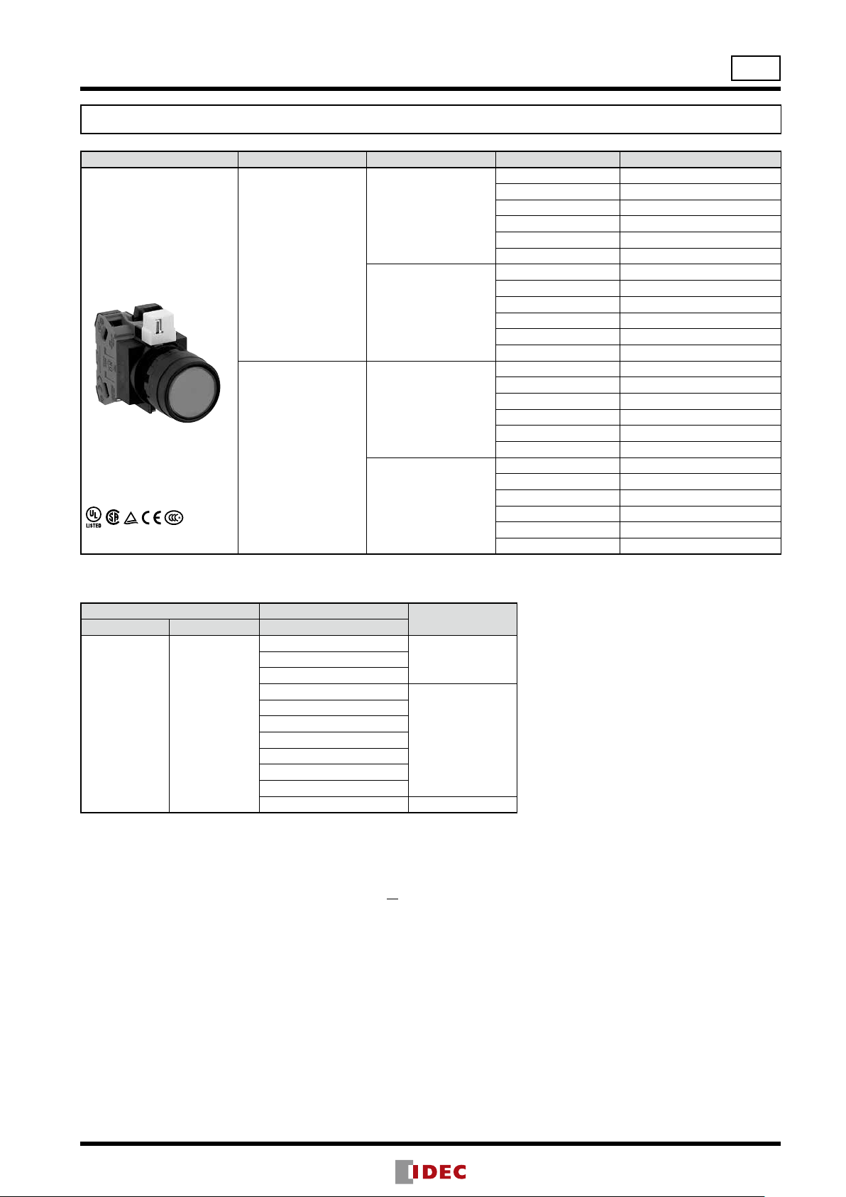
HW Series Switches & Pilot Lights
ø22
Function Pushbutton
Category
Shape
HW
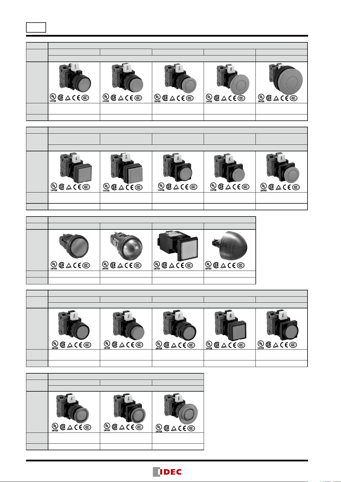
Series Selection Guide
Flush Extended ø29mm Mushroom ø40mm Mushroom ø60mm Mushroom
Momentary/Maintained Momentary
Model
Page 10 10 10 10 10
Function Pushbutton
Category
Shape
Model
Page 11 11 12 12 12
Function Pilot Light
Category Flush (Marking) Extended (Dome)
Shape
HW1B-M1
HW1B-A1
Square Flush Square Extended
HW2B-M1
HW2B-A1
HW1B-M2
HW1B-A2
HW2B-M2
HW2B-A2
HW1B-M3
HW1B-A3
Round Flush
w/Square Bezel
Momentary/Maintained
HW3B-M1
HW3B-A1
Square Flush (Marking)
HW1B-M4
HW1B-A4
Round Extended
w/Square Bezel
HW3B-M2
HW3B-A2
Jumbo Dome
HW1B-M5
ø29mm Mushroom
w/Square Bezel
HW3B-M3
HW3B-A3
Model HW1P-1 HW1P-2 HW2P-1 HW1P-5
Page 13 13 13 13
Function Illuminated Pushbutton
Category
Shape
Model
Page 11 11 12 12 12
Function Illuminated Pushbutton
Category
Shape
Model
Page 13 13 13
Flush Extended
HW1L-M1
HW1L-A1
Flush Extended
HW1L-M3
HW1L-A3
HW1L-M2
HW1L-A2
Momentary/Maintained
HW1L-M3
HW1L-A3
Extended w/Full Shroud
Momentary/Maintained
HW1L-MF2
HW1L-AF2
Extended w/Full Shroud
HW1L-M4
HW1L-A4
Square Flush
HW2L-M1
HW2L-A1
Flush w/Square Bezel
HW3L-M1
HW3L-A1
2

HW Series Selection Guide
Function Dual Pushbutton (w/o Pilot Light) Dual Pushbutton (w/ Pilot Light)
Category
Shape
Flush (top)
Flush (bottom)
Flush (top)
Extended (bottom)
Momentary/Interlocking
Flush (top)
Flush (bottom)
Flush (top)
Flush (bottom)
ø22
Model
Page 24 24 25 25
Function Selector Switch Illuminated Selector
Category Selector Pin Tumbler Key Disc Tumbler Key Knob Operator Lever Operator
Shape
Model HW1S
Page 29 30 32 34 34
Function
Category Standard Interlocking
Shape
Model HW1R HW1M HW1M-L
Page 42 43 43
HW7D-B11
HW7D-B21
Pushbutton Selector
HW7D-B12
HW7D-B22
HW1K-P
Mono-Lever Switch
HW7D-L11
HW7D-L21
HW1K HW1F
HW7D-L12
HW7D-L22
HW1F-L
3

ø22
HW Series Switches & Pilot Lights
Complete with finger-safe contact blocks
Ensure safety and save wiring time
• Locking lever removable contact blocks
• Spring-up screw contact blocks.
• Self-cleaning rolling action contacts.
• Degree of protection: IP65 (except dual pushbutton: IP40)
• Dual pushbutton switches available with two pushbuttons
and a pilot light integrated into one space-saving unit.
• A wide range of operating voltages for worldwide application
• UL, CSA rated, and EN compliant.
Application for dual pushbuttons:
Ideal for use as power switches and start/stop switches (available
with I/ON and O/OFF markings on the buttons and a pilot light in
the center).
Interlock type prevents two pushbuttons from being pressed at the
same time, providing the best solution for up/down switches.
Applicable Standards Mark File No. or Organization
UL508
CSA C22.2 No.14
EN60947-5-1
GB14048.5
UL Listing
File No. E68961
CSA
File No. LR92374
TÜV Rheinland
EU Low Voltage Directive
CCC
No. 2005010305145656
No. 2011010304454933 (pilot light)
Dual Pushbuttons
• DC-DC converter types are not approved by UL, CSA, and TÜV, and not CE compliant (operating voltage 90 to 140V DC)
Specifications and Ratings
Contact Ratings
Pushbuttons
Illuminated Pushbuttons
Dual Pushbuttons
Selector Switches
Illuminated Selector Switches
Pushbutton Selectors
Characteristics
Contact Ratings by Utilization Category
AC
Operational
Current
Note: The operational current represents the classication by making and breaking currents (IEC 60947-5-1).
•Minimum applicable load: 3V AC/DC, 5 mA (applicable range may vary with operating conditions and load types)
For the switches listed below, the rated current (load switching current) is reduced to a half of the rated operational current of the
contact block. The rated insulation voltage (600V) and the rated thermal current (10A) remain unchanged.
•3-position selector switches which contain J or S following 3 in the Part No. and which have cam code J or S. Example: HW1S-
3JT21N1
•All 4-position and 5-position selector switches
•All mono-lever switches
•All pushbutton selectors (circuit symbols E, F, N)
50/60 Hz
DC
Contact Block HW-G
Rated Insulation Voltage 600V
Rated Thermal Current 10A
Contact Ratings by Utilization Category
IEC 60947-5-1
Operating Voltage 24V 48V 50V 110V 220V 440V
AC-12 Control of resistive loads and solid state loads 10A — 10A 10A 6A 2A
AC-15 Control of electromagnetic loads (> 72 VA) 10A — 7A 5A 3A 1A
DC-12 Control of resistive loads and solid state loads 8A 4A — 2.2A 1.1A —
DC-13 Control of electromagnets 4A 2A — 1.1A 0.6A —
AC-15 (A600)
DC-13
4
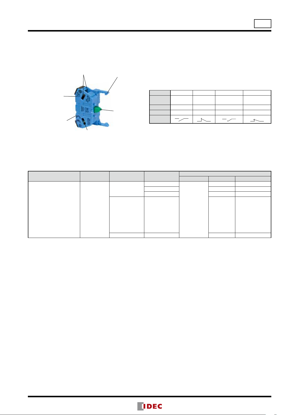
Contact Blocks
HW-G (Spring-up Screw Terminal)
Insertion from two directions
Ring or fork connectors can
also be used.
Snap-t latch
HW Series
ø22
Housing in different colors for NO
and NC contact.
Double-break rolling
action silver contacts
Contact material: silver
(gold-plated silver
available)
Note: For dimensions, see page 61.
Spring-up screw terminal is ready for wiring.
Screw is held captive.
Push rod
Color-coded for
different contacts
Part No. HW-G10 HW-G01 HW-G10R HW-G01R
Contact NO NC
Housing Blue Purple red Blue Purple red
Push Rod Green Red Black White
Contact
•Up to 2 layers (4 blocks) can be attached.
LED Illuminated Unit Specications
Unit Color Code ➁ Input Type
Full Voltage
A: amber
Pilot Light
Illuminated Pushbutton
Illuminated Selector Switch
•Use a pure white (PW) LED for yellow (Y) illumination.
•Yellow (Y) cannot be used with dual pushbuttons.
•For the LED lamp used in jumbo dome pilot lights, see the next page.
•110V/DC operating voltage has polarity. Check + terminal (X1) and – terminal (X2).
G: green
PW: pure white
R: red
S: blue
W: white
Y: yellow
Transformer
DC-DC Converter 110V DC LSTD-6➁ 6V AC/DC±10%
Operating
Voltage
6V AC/DC
12V AC/DC LSTD-1➁ 12V AC/DC±10%
24V AC/DC LSTD-2➁ 24V AC/DC±10%
100/110V AC
115/120V AC
200/220V AC
230/240V AC
380V AC
400/440V AC
480V AC
(50/60 Hz)
EM
(early make)EO(late break)
3
4
1 7 5
Lamp Base Part No. Voltage
BA9S/13
2 8 6
LED Lamp
LSTD-6➁ 6V AC/DC±10%
LSTD-6➁ 6V AC/DC±10%
5

ø22
X
X
Symbols
Recitication Diode
Resistor
X
HW Series
LED Lamp Ratings (LSTD)
(Except Jumbo Dome Pilot Lights)
Part No. LSTD-6➁ LSTD-1➁ LSTD-2➁
Lamp Base BA9S/13
Rated Voltage 6V AC/DC 12V AC/DC 24V AC/DC
Voltage Range 6V AC/DC ±10%
Current
Draw
Color Code
Lamp Base
Color
AC 8 mA 11 mA 11 mA
DC
A, R, W: 7 mA
G, PW, S: 5.5 mA
A (amber), G (green), PW (pure white),
R (red), S (blue), W (white)
Same as illumination color
12V AC/DC
±10%
10 mA 10 mA
Voltage Marking Die stamped on the base
24V AC/DC
±10%
LED Lamp Ratings (LSTDB)
(For Jumbo Dome Pilot Lights HW1P-5Q4 Only)
Part No. LSTDB-2➁
Lamp Base BA9S/13
Rated Voltage 24V AC/DC
Voltage Range 24V AC/DC ±10%
Current Draw 15 mA
Color Code
Life
(reference value)
A (amber), G (green), PW (pure white),
R (red), S (blue), W (white)
Approx. 20,000 hours
(until the brightness reduces to 50% the initial
value when lit at complete direct current of
the rated voltage under 25°C environment.)
A, R, W
X1
Approx. 50,000 hours
Life
(reference value)
Internal Circuit
(until the brightness reduces to 50% the initial
value when lit at complete direct current of the
rated voltage under 25°C environment.)
1
LED Chip
Recitification Diode
2
Zener Diode
Resistor
Internal Circuit
X2
G, PW, S
1
X2
•Use a pure white (PW) LED for yellow (Y) illumination.
•Use a pure white (PW) LED for yellow (Y) illumination.
Specications
Operating Temperature
Storage Temperature –40 to +80°C
Operating Humidity 45 to 85% RH (no condensation)
Contact Resistance
Insulation Resistance
Dielectric Strength
(Note)
Vibration Resistance Damage limits, Operating extremes: 5 to 55 Hz, amplitude 0.5 mm
Shock Resistance
Mechanical Life
(minimum operations)
Electrical Life
(minimum operations)
Weight
Note: Dielectric strength for dual pushbuttons are as follows:
Without pilot light: 2,500V AC, 1 minute (between live and dead metal parts)
With pilot light:
Full voltage type: 1,000V AC, 1 minute (between live and dead metal parts)
Transformer and DC-DC converter types: 2,000V AC, 1 minute (between live and dead metal parts)
–25 to +60°C (no freezing)
Illuminated units: –25 to +50°C Jumbo dome pilot lights: –25 to +55°C
50 mΩ maximum (initial value)
100 MΩ minimum (500V DC megger)
Between live and dead metal parts: 2,500V AC, 1 minute
(Full voltage illuminated units: 2,000V AC, 1 minute)
Damage limits: 1000 m/s
Operating extremes: 100 m/s
Pushbuttons, Illuminated pushbuttons
Momentary: 5,000,000
Maintained: 500,000
Dual pushbuttons: 500,000
Selector switches: 500,000
2
2
Key selector switches
Disc tumbler: 500,000
Pin tumbler: 100,000
Illuminated selector switches: 500,000
Pushbutton selectors: 250,000
Mono-lever switches: 250,000
Pushbuttons, Illuminated pushbuttons: 500,000 *1
Dual pushbuttons: 500,000 *1
Selector switches: 500,000 *2
Illuminated selector switches: 500,000 *2
Pushbutton selectors: 250,000 *2
Mono-lever switches: 250,000 *3
Key selector switches
Disc tumbler: 500,000 *2
Pin tumbler: 100,000 *2
*1 Switching frequency 1,800 operations/h, duty ratio 40%
*2 Switching frequency 1,200 operations/h, duty ratio 40%
*3 Switching frequency 900 operations/h, duty ratio 40%
66g (HW1B-M122 ), 20g (HW1P-1Q4), 84g (HW1L-M122Q4), 66g (HW1S-2T22), 94g (HW1K-2A22), 72g (HW1K-2JPC11),
84g (HW1F-222Q4), 71g (HW1R-2A22), 82g (HW1M-2222-22N9), 72g (HW7D-B111111), 90g (HW7D-L111111Q4)
LED Chip
Zener Diode
6
HW Series
R0.8 max.
Degree of Protection
Unit IEC 60529
All units except dual pushbutton switches IP65 (Note 1)
Dual pushbutton switches IP40 (Note 2)
Note 1:
When using a nameplate with the HW series, IP65 protection degree is achieved only when nameplates shown on page 44 are used.
Note 2: IP65 protection degree when HW9Z-D7D button cover is used.
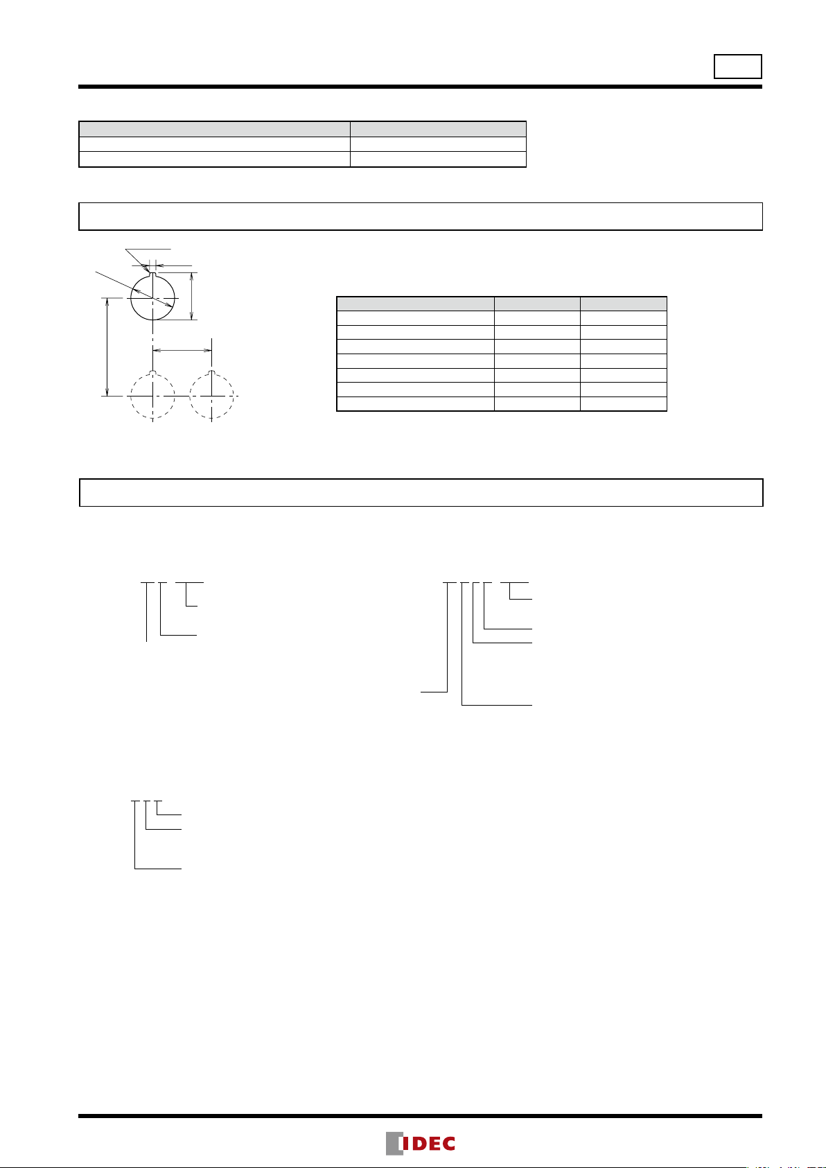
Mounting Hole Layout
ø22
+0.2
*3.2
ø22.3
+0.4
0
A
50 (45 min.)
*The 3.2 mm recess is for preventing rotation
and is not necessary when the nameplate or
anti-rotation ring is not used.
0
0
+0.4
24.1
B
30
The minimum mounting centers are applicable to switches with one layer of contact
blocks (two contact blocks). When two layers of contact blocks are mounted,
determine the minimum mounting centers in consideration of convenience for wiring.
Minimum Mounting Centers
Unit A B
ø40mm mushroom button 50 mm 40 mm
Pilot light 30 mm 30 mm
Pushbutton selector 50 mm 50 mm
Mono-lever switch 72 mm 72 mm
Jumbo dome pilot 85 mm 85 mm
Dual pushbutton switches 55 mm 30 mm
Illuminated selector switches 50 mm 50 mm
•When using the safety lever lock, determine the vertical spacing (A) in consideration
of convenience for installing and removing the safety lever lock.
Recommended vertical spacing: 100 mm
•See page 14 for close mounting of pilot lights.
Ordering Information
The Part No. development charts shown below can be used to specify the HW series other than those listed on the following pages. Goldplated silver contacts are also available.
Pushbuttons
HW1B-M1 11 R -MAU
Optional contact
MAU: Gold-plated silver contact
Contact arrangement code
10: 1NO 01: 1NC
11: 1NO-1NC 20: 2NO
02: 2NC 21: 2NO-1NC
12: 1NO-2NC 30: 3NO
03: 3NC 31: 3NO-1NC
22: 2NO-2NC 13: 1NO-3NC
40: 4NO 04: 4NC
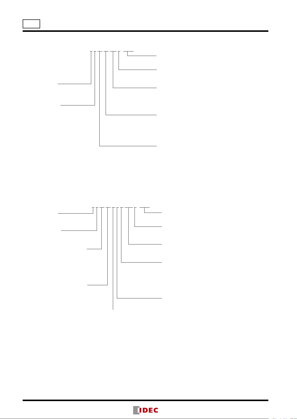
Pilot Lights
HW1P-1 H 2 R
Note: Transformer and DC-DC converter types can have two or four contact blocks only.
Button/lens color code
Contact arrangement code
10: 1NO 01: 1NC
11: 1NO-1NC 20: 2NO
02: 2NC 21: 2NO-1NC
12: 1NO-2NC 30: 3NO
03: 3NC 31: 3NO-1NC
22: 2NO-2NC 13: 1NO-3NC
40: 4NO 04: 4NC
Lens color code
Lamp code
0: Without lamp 2: LED (6V: LSTD)
3: LED (12V: LSTD) 4: LED (24V: LSTD)
Operating voltage code
LED
Q2: 6V AC/DC
Q3: 12V AC/DC
Q4: 24V AC/DC
H2: 100/110V AC
H22: 115/120V AC
M2: 200/220V AC
M42: 230/240V AC
S2: 380V AC
T2: 400/440V AC
T82: 480V AC
D2: 110V DC
Illuminated Pushbuttons
HW1L-M1 11 H 2 R -MAU
Optional contact
MAU: Gold-plated silver contact
Lens color code
Lamp code
0: Without lamp
2: LED (6V: LSTD)
3: LED (12V: LSTD)
4: LED (24V: LSTD)
Operating voltage code
LED
Q2: 6V AC/DC
Q3: 12V AC/DC
Q4: 24V AC/DC
H2: 100/110V AC
H22: 115/120V AC
M2: 200/220V AC
M42: 230/240V AC
S2: 380V AC
T2: 400/440V AC
T82: 480V AC
D2: 110V DC
•Transformertype,DC-DCconver typeisnotavailablewith
1NO,1NO,3NO,2NO-1NC,1NO-2NC,3NC).
•TransformertypehasLSTD-6lamp.
7
ø22
HW Series
Dual Pushbutton Switches
HW7D-B 1 1 10 02 GR 1 -MAU
Operation
1: Momentary
2: Interlock
Button style
1: Flush + Flush
2: Flush + Extended
Optional contact
MAU: Gold-plated silver contact
Button legends
Blank: Without legend
1: I/ON + O/OFF
Button color code
GR: Green (top)
Red (bottom)
WB:White (top)
Black (bottom)
Contact arrangement code (bottom button)
10: 1NO
01: 1NC
11: 1NO-1NC
20: 2NO
02: 2NC
Contact arrangement code (top button)
10: 1NO
01: 1NC
11: 1NO-1NC
20: 2NO
02: 2NC
Dual Pushbutton Switches with Pilot Light
HW7D-L 1 1 11 20 H 2 R -GR 1 -MAU
Operation
1: Momentary
2: Interlock
Button style
1: Flush+Flush
2:
Flush+Extended
Contact arrangement code
(top button)
10: 1NO
01: 1NC
11: 1NO-1NC
20: 2NO
02: 2NC
Contact arrangement code
(bottom button)
10: 1NO
01: 1NC
11: 1NO-1NC
20: 2NO
02: 2NC Operating voltage code
LED
Q2: 6V AC/DC
Q3: 12V AC/DC
Q4: 24V AC/DC
H2: 100/110V AC
H22: 115/120V AC
M2: 200/220V AC
M42: 230/240V AC
S2: 380V AC
T2: 400/440V AC
T82: 480V AC
Optional contact
MAU: Gold-plated silver contact
Button legends
Blank: Without legend
1: I/ON + O/OFF
Button color code
GR: Green (top), Red (bottom)
WB: White (top), Black (bottom)
Lamp color code
A: Amber
G: Green
PW: Pure white
R: Red
S: Blue
W: White
Lamp code
0: Without lamp
2: LED (6V: LSTD-6)
3: LED (12V: LSTD-1)
4: LED (24V: LSTD-2)
Note: Transformer type cannot have a contact arrangement of 3 contact blocks for the total of top and button)
8

HW Series
ø22
Selector Switches
HW1S-3 S T 22N9 -MAU
Operator position code
2: 2-position, maintained
21: 2-position, spring return from right
3: 3-position, maintained
31: 3-position, spring return from right
32: 3-position, spring return from left
33: 3-position, spring return two way
Pushbutton Selectors
HW1R-2 D 22N1 B -MAU
Illuminated Selector Switches
HW1F-2 11 H 2 R -MAU
Optional contact
MAU: Gold-plated
silver contact
Contact code
Cam code
Blank, J, or S
Knob operator
Optional contact
MAU: Gold-plated silver contact
Button color code
Optional contact
MAU: Gold-plated silver contact
Lens color code
Lamp code
0: Without lamp
2: LED (6V: LSTD)
3: LED (12V: LSTD)
4: LED (24V: LSTD)
Operating voltage code
Operator position code
2: 2-position, maintained
21: 2-position, spring return from right
3: 3-position, maintained
31: 3-position, spring return from right
32: 3-position, spring return from left
33: 3-position, spring return two way
•TransformertypehasLSTD-6lamp.
Contact code
Circuit category
Key Selector Switches (Pin Tumbler Key)
HW1K-2 J P A 01-501-MAU
Cam code
Blank, J, or S
Operator position code
2: 2-position, maintained
21: 2-position, spring return from right
3: 3-position, maintained
31: 3-position, spring return from right
32: 3-position, spring return from left
33: 3-position, spring return two way
Key Selector Switches (Disc Tumbler Key)
HW1K-3 J A 22 - 1H -MAU
Optional contact
MAU: Gold-plated silver contact
Different key number
1H / 2H / 3H
Key removal/retained positions
Cam code
Blank, J, or S
Optional contact
MAU: Gold-plated silver contact
Not specied: 500 (default key)
501-515: The key number is engraved on the key cylinder.
(default key is not engraved with a number)
Key removal/retained positions
2-position
A: Removable in all positions
B: Removable in the left only
C: Removable in the right only
3-position
A: Removable in all positions
B: Removable in the left and center
C: Removable in the right and center
D: Removable in center only
E: Removable in right and left
G: Removable in left only
H: Removable in right only
Note: The key cannot be removed in a spring return position.
Operator position code
2: 2-position, maintained
21: 2-position, spring return from right
3: 3-position, maintained
31: 3-position, spring return from right
32: 3-position, spring return from left
33: 3-position, spring return two way
Note: Key removal/retained positions, cam codes, and operator position codes are the same as pin tumbler keys.
9
M3.5 Terminal Screw
M3.5 Terminal Screw
Panel Thickness
M3.5 Terminal Screw
Panel Thickness
M3.5 Terminal Screw
Panel Thickness
ø22
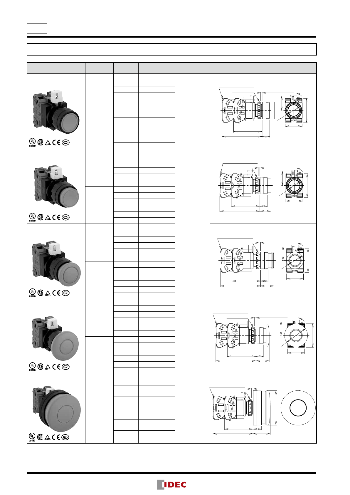
HW Series Pushbuttons
Flush / Extended / Mushroom Pushbuttons
Shape Operation Contact Part No.
Flush
HW1B-M1
HW1B-A1
Momentary
1NO HW1B-M110➀
1NC HW1B-M101➀
1NO-1NC HW1B-M111➀
2NO
2NC
2NO-2NC
HW1B-M120➀
HW1B-M102➀
HW1B-M122➀
1NO HW1B-A110➀
1NC HW1B-A101➀
Maintained
1NO-1NC HW1B-A111➀
2NO HW1B-A120➀
2NC HW1B-A102➀
2NO-2NC HW1B-A122➀
Extended
HW1B-M2
HW1B-A2
Momentary
1NO HW1B-M210➀
1NC HW1B-M201➀
1NO-1NC HW1B-M211➀
2NO
2NC
2NO-2NC
HW1B-M220➀
HW1B-M202➀
HW1B-M222➀
1NO HW1B-A210➀
1NC HW1B-A201➀
Maintained
1NO-1NC HW1B-A211➀
2NO HW1B-A220➀
2NC HW1B-A202➀
2NO-2NC HW1B-A222➀
ø29mm Mushroom
HW1B-M3
HW1B-A3
Momentary
1NO HW1B-M310➀
1NC HW1B-M301➀
1NO-1NC HW1B-M311➀
2NO
2NC
2NO-2NC
HW1B-M320➀
HW1B-M302➀
HW1B-M322➀
1NO HW1B-A310➀
1NC HW1B-A301➀
Maintained
1NO-1NC HW1B-A311➀
2NO HW1B-A320➀
2NC HW1B-A302➀
2NO-2NC HW1B-A322➀
ø40mm Mushroom
HW1B-M4
HW1B-A4
Momentary
1NO HW1B-M410➀
1NC HW1B-M401➀
1NO-1NC HW1B-M411➀
2NO
2NC
2NO-2NC
HW1B-M420➀
HW1B-M402➀
HW1B-M422➀
1NO HW1B-A410➀
1NC HW1B-A401➀
Maintained
1NO-1NC HW1B-A411➀
2NO HW1B-A420➀
2NC HW1B-A402➀
2NO-2NC HW1B-A422➀
ø60mm Mushroom
HW1B-M5
1NO
1NC
1NO-1NC
HW1B-M510➀
HW1B-M501➀
HW1B-M511➀
Momentary
2NO HW1B-M520➀
2NC HW1B-M502➀
2NO-2NC HW1B-M522➀
•Pushbuttons with one or three contact blocks contain a dummy block.
•Other contact arrangements and gold-plated silver contacts are also available. See page 7.
➀ Button
Color Code
Specify a
button color
code in place
of ➀ in the
Part No.
B: black
G: green
R: red
S: blue
W: white
Y: yellow
Specify a
button color
code in place
of ➀ in the
Part No.
B: black
G: green
R: red
M3.5 Terminal Screw
Locking Ring
49.4
(1 or 2 blocks)
69.4 (4 blocks)
Locking Ring
49.4
(1 or 2 blocks)
69.4 (4 blocks)
Locking Ring
49.4
(1 or 2 blocks)
69.4 (4 blocks)
Locking Ring
49.4
(1 or 2 blocks)
69.4 (4 blocks)
Locking Ring
49.4
(1 or 2 blocks)
69.4 (4 blocks)
Package Quantity: 1
Dimensions (mm)
Panel Thickness
0.8 to 6
ø29
13
Panel Thickness
0.8 to 6
13
19
0.8 to 6
13
23.2
0.8 to 6
13
23.2
0.8 to 6
ø60
15
30
ø23.6
ø23.6
LOCK
25
41.4
29.4
LOCK
25
41.4
29.4
LOCK
25
41.4
ø29
29.4
LOCK
25
41.4
ø40
29.4
10
HW Series Pushbuttons
1 contact bloc
Panel Thickness
M3.5 Terminal Screw
Panel Thickness
M3.5 Terminal Screw
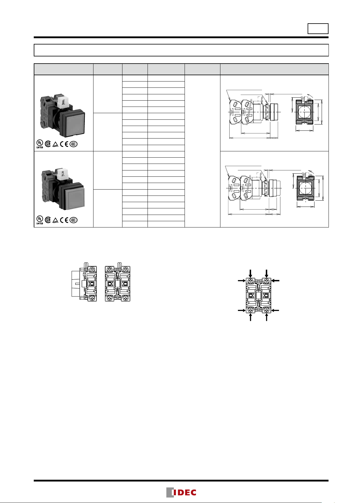
Square Flush / Square Extended Pushbuttons
Shape Operation Contact Part No.
Square Flush
HW2B-M1
HW2B-A1
Momentary
1NO HW2B-M110➀
1NC HW2B-M101➀
1NO-1NC HW2B-M111➀
2NO
2NC
2NO-2NC
HW2B-M120➀
HW2B-M102➀
HW2B-M122➀
1NO HW2B-A110➀
1NC HW2B-A101➀
Maintained
1NO-1NC HW2B-A111➀
2NO HW2B-A120➀
2NC HW2B-A102➀
2NO-2NC HW2B-A122➀
Square Extended
HW2B-M2
HW2B-A2
Momentary
1NO HW2B-M210➀
1NC HW2B-M201➀
1NO-1NC HW2B-M211➀
2NO
2NC
2NO-2NC
1NO
HW2B-M220➀
HW2B-M202➀
HW2B-M222➀
HW2B-A210➀
1NC HW2B-A201➀
Maintained
1NO-1NC HW2B-A211➀
2NO HW2B-A220➀
2NC HW2B-A202➀
2NO-2NC HW2B-A222➀
•Pushbuttons with one or three contact blocks contain a dummy block.
•Other contact arrangements and gold-plated silver contacts are also available. See page 7.
➀ Button
Color Code
Specify a
button color
code in place
of ➀ in the
Part No.
B: black
G: green
R: red
S: blue
W: white
Y: yellow
Locking Ring
49.4
(1 or 2 blocks)
69.4 (4 blocks)
Locking Ring
49.4
(1 or 2 blocks)
69.4 (4 blocks)
Package Quantity: 1
Dimensions (mm)
0.8 to 6
13
0.8 to 6
13
19
ø22
LOCK
25
41.4
29.6
29.4
LOCK
25
41.4
29.6
29.4
Contact Block (Bottom View)
2 contact blocks
k
4 contact blocks
Terminal Wiring
Arrows indicate access directions for wiring.
11

1 contact bloc
M3.5 Terminal Screw
M3.5 Terminal Screw
Panel Thickness
M3.5 Terminal Screw
ø22
HW Series Pushbuttons
Round Button with Square Bezel Pushbuttons
Shape Operation Contact Part No.
Round Flush
with Square Bezel
HW3B-M1
HW3B-A1
Momentary
1NO HW3B-M110➀
1NC HW3B-M101➀
1NO-1NC HW3B-M111➀
2NO HW3B-M120➀
2NC HW3B-M102➀
2NO-2NC HW3B-M122➀
1NO HW3B-A110➀
1NC HW3B-A101➀
Maintained
1NO-1NC HW3B-A111➀
2NO HW3B-A120➀
2NC HW3B-A102➀
2NO-2NC HW3B-A122➀
Round Extended
with Square Bezel
HW3B-M2
HW3B-A2
Momentary
1NO HW3B-M210➀
1NC HW3B-M201➀
1NO-1NC HW3B-M211➀
2NO HW3B-M220➀
2NC HW3B-M202➀
2NO-2NC HW3B-M222➀
1NO HW3B-A210➀
1NC HW3B-A201➀
Maintained
1NO-1NC HW3B-A211➀
2NO HW3B-A220➀
2NC HW3B-A202➀
2NO-2NC HW3B-A222➀
ø29mm Mushroom
with Square Bezel
HW3B-M3
HW3B-A3
Momentary
1NO HW3B-M310➀
1NC HW3B-M301➀
1NO-1NC HW3B-M311➀
2NO HW3B-M320➀
2NC HW3B-M302➀
2NO-2NC HW3B-M322➀
1NO HW3B-A310➀
1NC HW3B-A301➀
Maintained
1NO-1NC HW3B-A311➀
2NO HW3B-A320➀
2NC HW3B-A302➀
2NO-2NC HW3B-A322➀
•Pushbuttons with one or three contact blocks contain a dummy block.
•Other contact arrangements and gold-plated silver contacts are also available. See page 7.
➀ Button Color
Code
Specify a
button color
code in place
of ➀ in the Part
No.
B: black
G: green
R: red
S: blue
W: white
Y: yellow
Locking Ring
49.4
(1 or 2 blocks)
69.4 (4 blocks)
Locking Ring
49.4
(1 or 2 blocks)
69.4 (4 blocks)
Locking Ring
49.4
(1 or 2 blocks)
69.4 (4 blocks)
Package Quantity: 1
Dimensions (mm)
Panel Thickness
0.8 to 6
13
Panel Thickness
0.8 to 6
13
19
0.8 to 6
13
23.2
ø23.6
ø29
LOCK
25
41.4
29.6
29.4
LOCK
25
41.4
29.6
29.4
LOCK
25
41.4
29.6
29.4
12
Contact Block (Bottom View)
2 contact blocks
k
4 contact blocks
Terminal Wiring
Arrows indicate access directions for wiring.
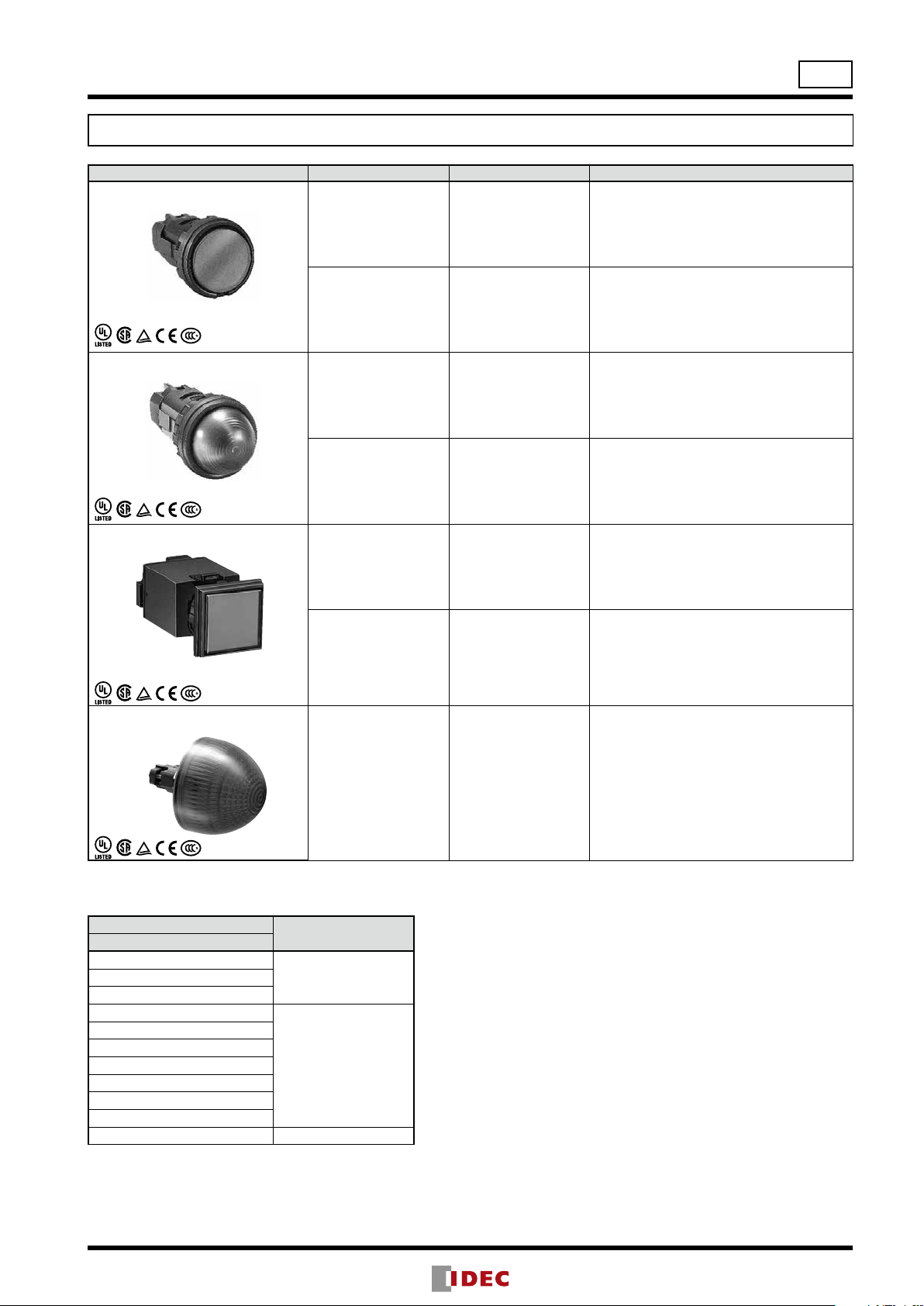
HW Series Pilot Lights
Round Flush / Dome / Square Flush / Jumbo Dome Pilot Lights
Shape Lamp Part No. ➁ Lens/Illumination Color Code
Round Flush
HW1P-1
Without Lamp HW1P-1Q0➁
A: amber, G: green, R: red, S: blue, W: white,
Y: yellow
ø22
Package Quantity: 1
(Photo: Full Voltage)
Dome
HW1P-2
(Photo: Full Voltage)
Square Flush
HW2P-1
(Photo: Transformer)
Jumbo Dome Pilot Light
HW1P-5
LED HW1P-1➂➁
Without Lamp HW1P-2Q0➁
LED HW1P-2➂➁
Without Lamp HW2P-1Q0➁
LED HW2P-1➂➁
A: amber, G: green, PW: pure white, R: red,
S: blue, W: white, Y: yellow
A: amber, G: green, R: red, S: blue, W: white,
Y: yellow
A: amber, G: green, PW: pure white, R: red,
S: blue, W: white, Y: yellow
A: amber, G: green, R: red, S: blue, W: white,
Y: yellow
A: amber, G: green, PW: pure white, R: red,
S: blue, W: white, Y: yellow
LED HW1P-5Q4➁
A: amber, G: green, PW: pure white, R: red,
S: blue, W: white, Y: yellow
Designation Code
Specify an designation code in place of ➂ in the Part No.
➂ Operating Voltage Code
LED
Q2: 6V AC/DC
Q4: 24V AC/DC
H2: 100/110V AC
H22: 115/120V AC
M2: 200/220V AC
M42: 230/240V AC
S2: 380V AC
T2: 400/440V AC
T82: 480V AC
D2: 110V DC
•Use a pure white (PW) LED lamp for yellow (Y) illumination.
•Jumbo dome pilot lights contain an exclusive LED. See page 49.
*DC-DC converter types are not approved by UL, CSA, and TÜV, and not CE compliant (operating voltage 90 to 140V DC)
Input Type
Full VoltageQ3: 12V AC/DC
Transformer
DC-DC Converter*
13
ø22
Panel Thickness 1 to 5
+0.2
R0.8 max.
30 min.
+0.4
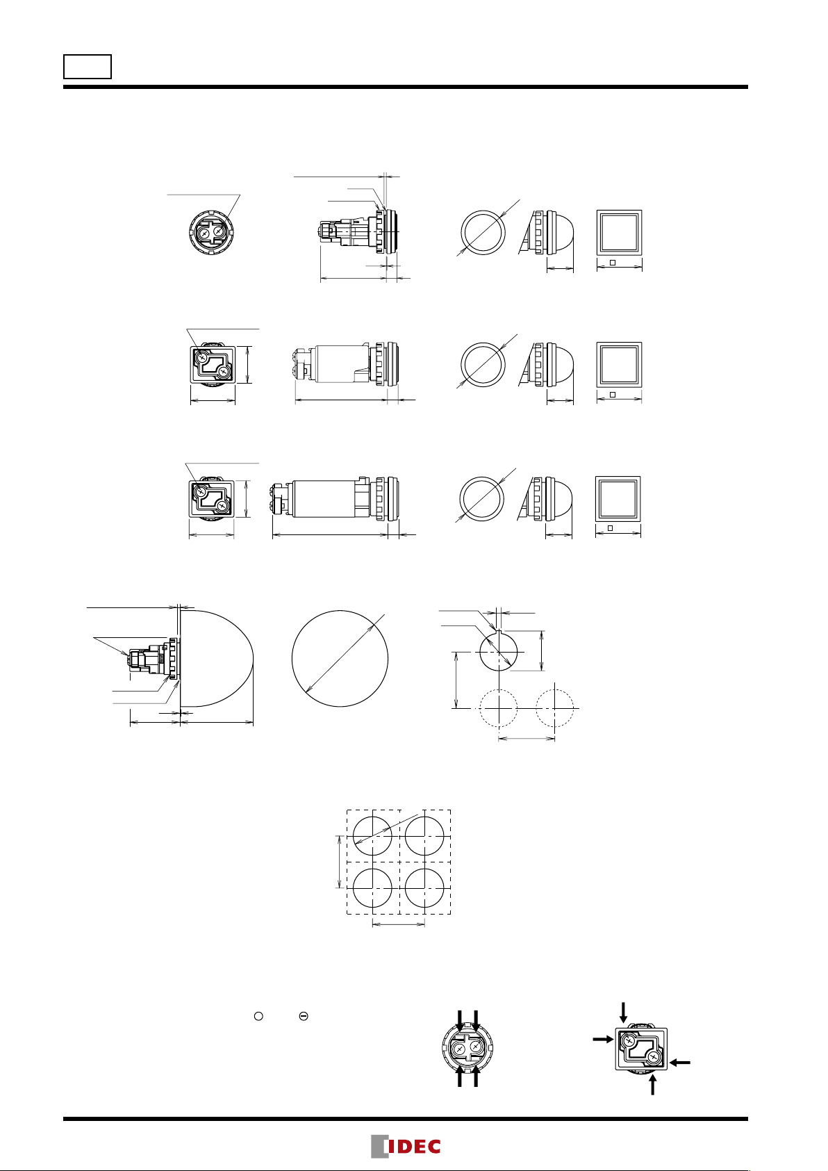
HW Series Pilot Lights
Dimensions
Pilot Light (except jumbo dome pilot light)
[Full Voltage]
M3.5 Terminal Screw
X2
X1
Panel Thickness 0.8 to 6
Gasket
Locking Ring
0.5
Flush
743.3
Round/Dome
ø29
Dome
17.5
Square Flush
29.6
[Transformer 240V AC maximum]
17.5
Square Flush
29.6
M3.5 Terminal Screw
X1
X2
24
29.6
Flush
760.8
Round/Dome
Dome
ø29
[Transformer 380 AC mimimum]
[DC-DC Converter]
M3.5 Terminal Screw
X1
X2
24
29.6
76.2
Flush Round/Dome
7
Dome
ø29
17.5
Square Flush
29.6
All dimensions in mm.
Jumbo Dome Pilot Light Mounting Hole Layout for Jumbo Dome Pilot Light
0
3.2
0
+0.4
24.1
85
M3.5 Terminal Screw
Locking Ring
Rubber Gasket
34.4
ø66
0.5
50.5
ø22.3
+0.4
0
85
Close Mounting
Pilot Light (except jumbo dome pilot light)
Close mounting on 30mm centers
Degree of protection: IP65
Terminal Wiring
14
1. Arrows indicate access directions for wiring.
2. For 110V DC types, terminal X1 is + , X2 is .
3. Lamp terminals do not have any polarity (except 110V
DC)
ø22.3
30 min.
0
When mounting transformer or DC-DC converter type
units on 30mm centers vertically and horizontally,
keep the ambient temperature below 40°C.
Full Voltage Transformer
X2
X1
DC-DC Converter
X1
X2
HW Series Illuminated Pushbuttons
Round Flush Illuminated Pushbuttons
Shape Operation Lamp Contact Part No.
Round Flush
HW1L-M1
HW1L-A1
Without Lamp
Momentary
LED
Without Lamp
Maintained
LED
ø22
Package Quantity: 1
1NO HW1L-M110Q0➁
1NC HW1L-M101Q0➁
1NO-1NC HW1L-M111Q0➁
2NO HW1L-M120Q0➁
2NC HW1L-M102Q0➁
2NO-2NC HW1L-M122Q0➁
1NO HW1L-M110➂➁ (Note 1)
1NC HW1L-M101➂➁ (Note 1)
1NO-1NC HW1L-M111➂➁
2NO HW1L-M120➂➁
2NC HW1L-M102➂➁
2NO-2NC HW1L-M122➂➁
1NO HW1L-A110Q0➁
1NC HW1L-A101Q0➁
1NO-1NC HW1L-A111Q0➁
2NO HW1L-A120Q0➁
2NC HW1L-A102Q0➁
2NO-2NC HW1L-A122Q0➁
1NO HW1L-A110➂➁ (Note 1)
1NC HW1L-A101➂➁ (Note 1)
1NO-1NC HW1L-A111➂➁
2NO HW1L-A120➂➁
2NC HW1L-A102➂➁
2NO-2NC HW1L-A122➂➁
Designation Code
Specify a designation code in place of ➁ or ➂ in the Part No.
➁ Lens/Illumination Color Code ➂ Operating Voltage Code
Without Lamp LED LED
Q2: 6V AC/DC
A: amber
G: green
R: red
S: blue
W: white
Y: yellow
•Use a pure white (PW) LED lamp for yellow (Y) illumination.
•Other contact arrangements and gold-plated silver contacts available. See page 7.
*DC-DC converter types are not approved by UL, CSA, and TÜV, and not CE compliant (operating voltage 90 to 140V DC)
Note 1: Only full voltage types are available.
Note 2: For A (amber), G (green), R (red) and S (blue) LED illumination, add W before the color code when white lens unit (clear lens +
white marking plate) is required. (Eg: HW1L-M111Q4WA)
A: amber
G: green
PW: pure white
R: red
S: blue
W: white
Y: yellow
(Note 2)
Q4: 24V AC/DC
H2: 100/110V AC
H22: 115/120V AC
M2: 200/220V AC
M42: 230/240V AC
S2: 380V AC
T2: 400/440V AC
T82: 480V AC
D2: 110V DC
Input Type
Full VoltageQ3: 12V AC/DC
Transformer
DC-DC Converter*
15

ø22
HW Series Illuminated Pushbuttons
Round Extended Illuminated Pushbuttons
Shape Operation Lamp Contact Part No.
Round Extended
HW1L-M2
HW1L-A2
Without Lamp
Momentary
LED
Without Lamp
Maintained
LED
Package Quantity: 1
1NO HW1L-M210Q0➁
1NC HW1L-M201Q0➁
1NO-1NC HW1L-M211Q0➁
2NO HW1L-M220Q0➁
2NC HW1L-M202Q0➁
2NO-2NC HW1L-M222Q0➁
1NO HW1L-M210➂➁ (Note 1)
1NC HW1L-M201➂➁ (Note 1)
1NO-1NC HW1L-M211➂➁
2NO HW1L-M220➂➁
2NC HW1L-M202➂➁
2NO-2NC HW1L-M222➂➁
1NO HW1L-A210Q0➁
1NC HW1L-A201Q0➁
1NO-1NC HW1L-A211Q0➁
2NO HW1L-A220Q0➁
2NC HW1L-A202Q0➁
2NO-2NC HW1L-A222Q0➁
1NO HW1L-A210➂➁ (Note 1)
1NC HW1L-A201➂➁ (Note 1)
1NO-1NC HW1L-A211➂➁
2NO HW1L-A220➂➁
2NC HW1L-A202➂➁
2NO-2NC HW1L-A222➂➁
Designation Code
Specify a designation code in place of ➁ or ➂ in the Part No.
➁ Lens/Illumination Color Code ➂ Operating Voltage Code
Without Lamp LED LED
Q2: 6V AC/DC
A: amber
G: green
R: red
S: blue
W: white
Y: yellow
•Use a pure white (PW) LED lamp for yellow (Y) illumination.
•Other contact arrangements and gold-plated silver contacts available. See page 7.
*DC-DC converter types are not approved by UL, CSA, and TÜV, and not CE compliant (operating voltage 90 to 140V DC)
Note 1: Only full voltage types are available.
Note 2: For A (amber), G (green), R (red) and S (blue) LED illumination, add W before the color code when white lens unit (clear lens +
white marking plate) is required. (Eg: HW1L-M211Q4WA)
A: amber
G: green
PW: pure white
R: red
S: blue
W: white
Y: yellow
(Note 2)
Q4: 24V AC/DC
H2: 100/110V AC
H22: 115/120V AC
M2: 200/220V AC
M42: 230/240V AC
S2: 380V AC
T2: 400/440V AC
T82: 480V AC
D2: 110V DC
Input Type
Full VoltageQ3: 12V AC/DC
Transformer
DC-DC Converter*
16

HW Series Illuminated Pushbuttons
Round Extended with Full Shroud Illuminated Pushbuttons
Shape Operation Lamp Contact Part No.
Round Extended
with Full Shroud
HW1L-MF2
HW1L-AF2
Without Lamp
Momentary
LED
Without Lamp
Maintained
LED
1NO HW1L-MF210Q0➁
1NC HW1L-MF201Q0➁
1NO-1NC HW1L-MF211Q0➁
2NO HW1L-MF220Q0➁
2NC HW1L-MF202Q0➁
2NO-2NC HW1L-MF222Q0➁
1NO HW1L-MF210➂➁ (Note 1)
1NC HW1L-MF201➂➁ (Note 1)
1NO-1NC HW1L-MF211➂➁
2NO HW1L-MF220➂➁
2NC HW1L-MF202➂➁
2NO-2NC HW1L-MF222➂➁
1NO HW1L-AF210Q0➁
1NC HW1L-AF201Q0➁
1NO-1NC HW1L-AF211Q0➁
2NO HW1L-AF220Q0➁
2NC HW1L-AF202Q0➁
2NO-2NC HW1L-AF222Q0➁
1NO HW1L-AF210➂➁ (Note 1)
1NC HW1L-AF201➂➁ (Note 1)
1NO-1NC HW1L-AF211➂➁
2NO HW1L-AF220➂➁
2NC HW1L-AF202➂➁
2NO-2NC HW1L-AF222➂➁
ø22
Package Quantity: 1
Designation Code
Specify a designation code in place of ➁ or ➂ in the Part No.
➁ Lens/Illumination Color Code ➂ Operating Voltage Code
Without Lamp LED LED
Q2: 6V AC/DC
A: amber
G: green
R: red
S: blue
W: white
Y: yellow
•Use a pure white (PW) LED lamp for yellow (Y) illumination.
•Other contact arrangements and gold-plated silver contacts available. See page 7.
*DC-DC converter types are not approved by UL, CSA, and TÜV, and not CE compliant (operating voltage 90 to 140V DC)
Note 1: Only full voltage types are available.
Note 2: For A (amber), G (green), R (red) and S (blue) LED illumination, add W before the color code when white lens unit (clear lens +
white marking plate) is required. (Eg: HW1L-M211Q4WA)
A: amber
G: green
PW: pure white
R: red
S: blue
W: white
Y: yellow
(Note 2)
Q4: 24V AC/DC
H2: 100/110V AC
H22: 115/120V AC
M2: 200/220V AC
M42: 230/240V AC
S2: 380V AC
T2: 400/440V AC
T82: 480V AC
D2: 110V DC
Input Type
Full VoltageQ3: 12V AC/DC
Transformer
DC-DC Converter*
17
 Loading...