

IDEC ID CW4K31AE20 Datasheet

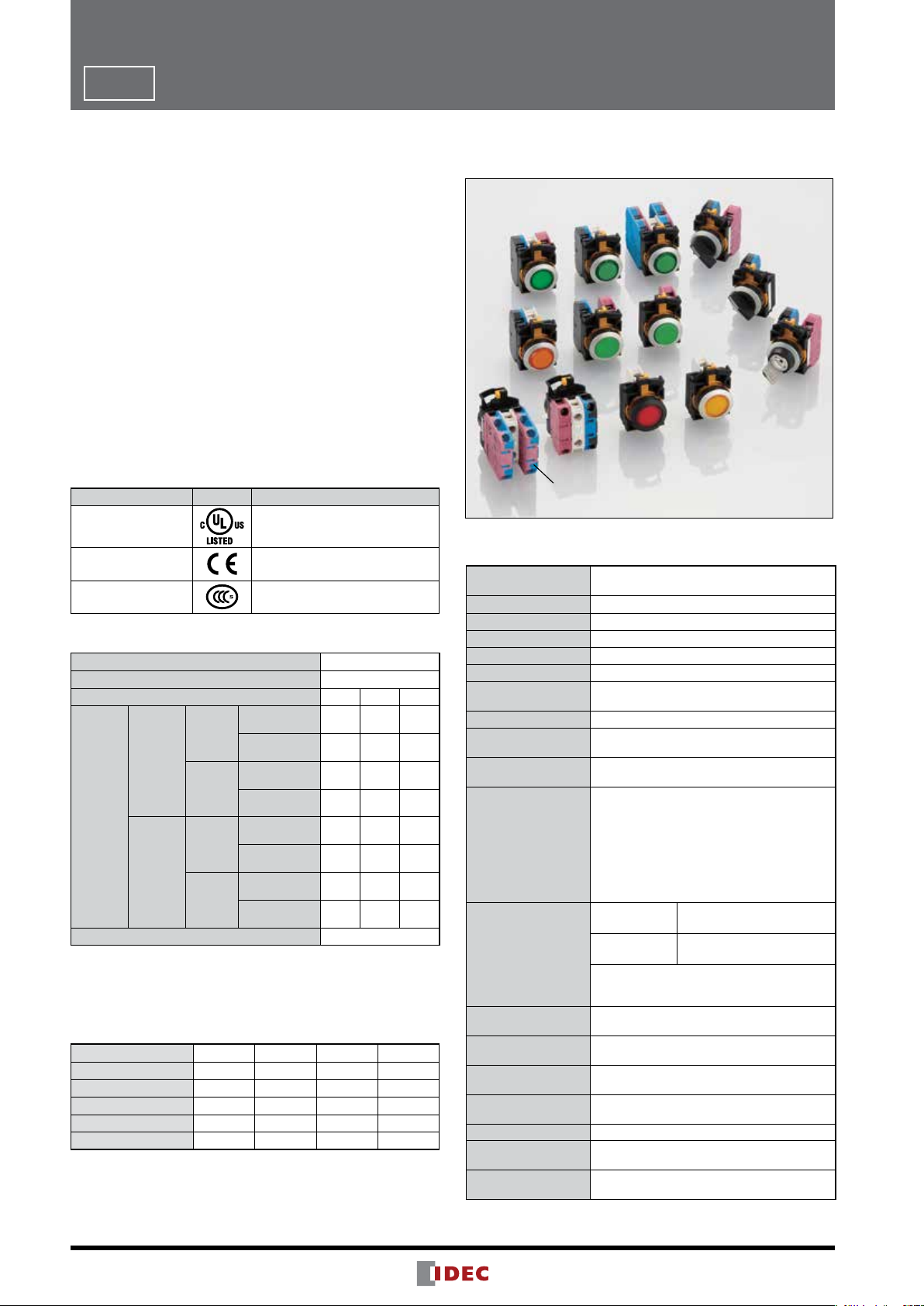
Flush Silhouette Switches
ø22
Double
Contact
Block
mm CW Series
Double contact block
Double contact block
4-contact configurations available
Only 59.9mm behind the panel
Single contact block
Shortest
in its class
Safety
Two-action removal
IDEC's third-generation safety
construction reduces labor and
enhances level of safety.
Only 39.9mm behind the panel
2.5mm-thick bezel
Sleek
design

Safety in style and sophistication
ø22mm CW Series
Flush Silhouette Switches
Double
Contact
Block
Shortest
in its class
(as of March
2013)
New double contact blocks with four-contact configurations.
(Illuminated pushbuttons, pushbuttons, selector switches, key selector switches)
Double
contact blocks
Single
contact blocks
Short depth behind the panel for compact equipment.
Double: 59.9mm (maintained: 64.6mm) Single: 39.9mm (maintained: 44.6mm)
Switching capacity is 120V AC, 10A (resistive load). The compact style requires less depth behind the panel.
Can be used with IDEC's FB and other 22mm control boxes. No transformer needed for any voltage.
2.5mm-thick
Double
contact block
Single
contact block
bezel
2
Fits in
small
space
Four-contact
illuminated pushbutton
Conventional
less space
40%
less weight
50%
CW series
double contact block
(Actual size)(Actual size)
Control Panel Control Panel
Devices
Two-contact
illuminated pushbutton
Conventional
Devices
50%
59%
single contact block
less space
less weight
CW series
39.9mm59.9mm
Devices
Devices

Sleek and stylish switches and pilot lights
with a 2.5mm-thick bezel
The CW series gives a sleek, stylish image to your machines or control panels. The surface is safer with less chance of unexpected operation or accidents by hitting the projections, and also is cleaner with
less dust build-up.
Safety
Third-generation
safety construction
Two-action removal of contact blocks
IDEC’s original two-action push-turn locking lever provides a higher
level of safety by preventing unexpected release of the locking lever.
Whether the contact block is installed securely can be checked easily
from the back of the panel, with the position of the locking lever.
Locking lever integrated
with guard
Prevents locking lever from unexpected release or damage by
trapped wires.
Variety
➁ Tu r n
Removing contact blocks
Locking Lever
Guard
➀ Push
IP20 Finger-safe Terminal
Finger-safe, IP20 terminal prevents
electrical shock.
Illuminated
Pushbuttons
(round flush or
extended)
Black bezel available
See page 8. See page 10. See page 11.
Pilot lights
(round flush or
extended)
Black bezel available
Black bezel available
Colors
Illuminated Pushbuttons/Pilot Lights Pushbuttons Bezels
Red (R) Green (G) Yellow (Y)Amber (A) Blue (S)
Pure White (PW)
Pushbuttons
(round flush or
extended)
Black Green Red YellowBlue White
Selector Switches
(knob or lever)
2- and 3-position
Knob Lever
Black bezel available Black bezel available
Low extension with flush silhouette.
See page 12.
Key Selector Switches
Wave key
7 different key numbers
Black bezel available
Hard to duplicate, wave-key
ensures a high level of safety.
See page 14.
Metallic Black (plastic)
3
ø22
Flush Silhouette Switches CW Series
Flush bezel projects only 2.5mm from front of panel
Only 39.9mm depth behind the panel (single contact block, momentary).
•ø22.3mm mounting hole compliant with IEC 60947-5-1
•3.5-mm operator travel for pushbuttons ensures comfort-
able and reliable operation.
•Black plastic and metallic bezels available.
•Four-contact configuration is available with double contact
blocks.
•Direct opening NC contact ensures shutdown without
failure.
•Seven different keys can be chosen for key selector
switches.
•10A contact rating. Up to three contact blocks for nonilluminated and two contact blocks for illuminated units
can be connected.
•Contact blocks can be removed by the two-action locking
lever integrated with a guard, ensuring safety.
•IP20 finger-safe screw terminals
•IP66/67, UL Type 4X degree of protection from panel front
(see Table 1).
Applicable Standards Mark File No. or Organization
UL508
CSA C22.2 No.14
EN60947-5-1
GB14048.5
UL/c-UL File No. E68961
EU Low Voltage Directive
No. 2012010305589209
(Pilot lights: No. 2012010304567962)
Contact Ratings
Rated Insulation Voltage (Ui) 300V
Rated Thermal Current (Ith) 10A
Rated Operating Voltage (Ue) 24V 120V 240V
Resistive Load
AC
Electrical
Life
50,000
operations
Rated
Operating
Current
(Ie)
Electrical
Life
100,000
operations
Contact Material Silver
•Minimum applicable load (reference value): 3V AC/DC, 5 mA
(Applicable range is subject to the operating conditions and load.)
Note: The operational current represents the classification by making and
breaking currents (IEC 60947-5-1).
•UL, c-UL rating: A300, CCC rating: A300
50/60 Hz
DC
AC
50/60 Hz
DC
(AC-12)
Inductive Load
(AC-15)
Resistive Load
(DC-12)
Inductive Load
(DC-13)
Resistive Load
(AC-12)
Inductive Load
(AC-15)
Resistive Load
(DC-12)
Inductive Load
(DC-13)
Table 1 (Degree of Protection)
IP65 IP66 IP67 UL Type 4X
Illuminated Pushbutton Yes Yes (Note) Yes (Note) Yes (Note)
Pilot Light Yes Yes No Yes
Pushbutton Yes Yes (Note) Yes (Note) Yes (Note)
Selector Switch Yes Yes Yes Yes
Key Selector Switch Yes Yes No Yes
Note: When used with rubber boot (CW9Z-D11, -D12)
10A 10A 6A
10A 6A 3A
8A 2.2A 1.1A
4A 1.1A 0.55A
5A 5A 3A
5A 3A 1.5A
4A 1.1A 0.55A
2A 0.55A 0.27A
Specifications
Operating Temperature
Operating Humidity 45 to 85% RH (no condensation)
Storage Temperature –40 to +80°C (no freezing)
Contact Resistance 50 mΩ maximum (initial value)
Insulation Resistance 100 MΩ minimum (500V DC megger)
Overvoltage Category II (IEC 60664-1)
Impulse Withstand
Voltage
Pollution Degree 3 (IEC 60947-5-1)
Vibration Resistance
Shock Resistance
Mechanical Life
(minimum operations)
Electrical Life
(minimum operations)
Degree of Protection
(IEC 60529)
Short-circuit Protection
Electrical Shock
Protection
Terminal Style
Bezel Material Polyamide
Applicable Wire Size
Recommended
Tightening Torque
Double Contact Block
Non-illuminated: –25 to +60°C (no freezing)
LED illuminated: –25 to +55°C (no freezing)
2.5 kV (IEC 60664-1/60947-5-1)
Operating extremes: 5 to 55Hz, amplitude 0.5 mm
Damage limits: 30 Hz, amplitude 1.5 mm
Operating extremes: 100 m/s
Damage limits: 1000 m/s
Illuminated pushbutton/pushbutton
Momentary: 2,000,000 (single contact block)
1,000,000 (double contact block)
Maintained: 250,000 (single contact block)
100,000 (double contact block)
Selector switch: 250,000 (single contact block)
100,000 (double contact block)
Key selector switch: 250,000 (single contact block)
Single contact
block
Double contact
block
Switching frequency
Momentary: 1800 operations/h
Maintained: 900 operations/h
Panel front: See table to the left
Terminal: IP20 (IEC 60529)
250V/10A fuse
(Type aM IEC 60269-1, IEC 602069-2)
Class II (IEC 61140)
Screw terminal (M3.5 slotted Phillips screw)
(Ring terminal cannot be used.)
Up to 2 wires of 2 mm2 (solid wire ø1.6) maximum
(AWG14 to 16)
Terminal: 1.0 to 1.3 N·m
Locking ring: 1.2 N·m
2
2
100,000 (double contact block)
50,000 (see Contact Ratings)
100,000 (see Contact Ratings)
25,000 (see Contact Ratings)
50,000 (see Contact Ratings)
4

Rectifying Diode
R
X2
X1
C
X1
X2
R
Rectifying Diode
R0.8 max.
+0.2
3.2
Flush Silhouette Switches CW
Series
ø22
Weight (Examples)
Illuminated Pushbutton
Pilot Light 27g (CW1P-1EQH)
Pushbutton
Selector Switch 48g (CW1S-2E03, 3 contacts)
46g (CW1L-M1E02QH, 2 contacts)
62g (CW1L-M1E22QH, 4 contacts)
45g (CW1B-M1E03, 3 contacts)
52g (CW1B-M1E22, 4 contacts)
Direct Opening of Key Selector Switch
Applicable Type 2-position (3NC) 3-position (2NC)
Minimum Operator Angle for
Direct Opening Action
Minimum Operator Torque
for Direct Opening Action
Maximum Operator Angle 90° 45°
90° 45°
0.2 N·m 0.3 N·m
55g (CW1S-2E22, 4 contacts)
Key Selector Switch
61g (CW1K-2AE03, 3 contacts)
68g (CW1K-2AE22, 4 contacts)
LED Module
Rated Insulation Voltage (Ui) 250V
Rated Operating Voltage (Ue) 6V AC/DC 12V AC/DC 24V AC/DC 100/120V AC 200/220V AC 230/240V AC
Operating Voltage Range 6V AC/DC±10%
12V AC/DC ±10% 24V AC/DC ±10%
Illumination Color Code ➁ A (amber), G (green), PW (pure white), R (red), S (blue)
LED Module Part No. CW-EAQ2➁ CW-EAQ3➁ CW-EAQ4➁ CW-EAQH➁ CW-EAQM➁ CW-EAQM4➁
Current Draw 15 mA 15 mA 16.5 mA 18 mA 20 mA 18 mA
Life (reference value)
Internal Circuit
Approx. 30,000 hours
(the illuminance is reduced to 50% of the initial intensity when used on complete DC at 25°C.)
LED Chip
R
Zener Diode
Resistor
100/120V AC ±10% 200/220V AC ±10% 230/240V AC ±10%
LED Chip
R
R
Zener Diode
Resistor
Capacitor
• Specify an illumination color code in place of ➁ in the Part No.
• Use the pure white (PW) LED module for yellow illumination.
Contact Blocks
Single Contact Block Double Contact Block
Contact
Part No.
Shape
Housing Color
Push Rod Color
Terminal No.
Weight (approx.)
Push
Rod
Single Contact Block
YW-E10R
M3.5
Terminal Screw
Housing
1NO 1NC 2NO 2NC 1NO-1NC
YW-E10R YW-E01 YW-EW2R0 YW-EW02 YW-EW1R1
Blue/Black Reddish Purple Blue/Black Reddish Purple Reddish Purple/Blue
Black Red Black Red Gray
3-4 1-2
11g 19g
M3.5 Terminal Screw
(1st tier)
Push
Rod
Double Contact Block
YW-EW1R1
Housing
1st tier: 13-14
2nd tier: 23-24
M3.5 Terminal Screw
(2nd tier)
1st tier: 11-12
2nd tier: 21-22
Mounting Hole Layout
IEC 60947-5-1 compliant
0
ø22.3
+0.4
0
0
+0.4
24.1
1st tier: (NO) 13-14
2nd tier: (NC) 21-22
50
Note: Determine mounting
30
centers to ensure easy
operation.
5
ø22
Flush Silhouette Switches CW3
Part No. Development
Illuminated Pushbuttons
Series
Note: Please use these char ts to interpret the part numbers
as all combinations are not possible to be created.
Bezel Color
Code Bezel Color
1
Black
4
Metallic
Operation
Code Operation
M Momentary
A Maintained
Shape
Code Shape
1 Round Flush
2 Round Extended
Option
Code Option Part No. Example
W White lens type (when light is off)
• For white lens, clear lens is used instead of colored lens for amber,
green, red, and blue illuminated pushbuttons. Amber, green, red, or
blue LED units are used.
CW1L-M1E10Q4W➁
Pilot Lights
CW 1 P - 1 E Q4 ➁
Bezel Color
Code Bezel Color
1
Black
4
Metallic
Shape
Code Shape
1
Round Flush
2
Round Extended
Option
CW 1 L - M 1 E 10 Q4 ➁
Code
W
White lens type (when light is off)
• For white lens, clear lens is used instead of colored lens for amber,
green, red, and blue illuminated pushbuttons. Amber, green, red, or blue
LED units are used.
Option Part No. Example
CW1P-1EQ4W➁
Illumination Color
Code Color Code Color
A
Amber
G
Green S Blue
PW Pure White Y Yellow
R
Rated Voltage
Code Rated Voltage Code Rated Voltage
Q2 6V AC/DC QH 100/120V AC
Q3 12V AC/DC QM 200/220V AC
Q4 24V AC/DC QM4 230/240V AC
Contact Configuration
Code
10 1NO 20 2NO
01 1NC 02 2NC
11 1NO-1NC 22 2NO-2NC
Contact
Configuration
Code
Illumination Color
Code Color Code Color
A
Amber
G
Green S Blue
PW Pure White Y Yellow
R
Red
Rated Voltage
Code Rated Voltage Code Rated Voltage
Q2 6V AC/DC QH 100/120V AC
Q3 12V AC/DC QM 200/220V AC
Q4 24V AC/DC QM4 230/240V AC
Red
Contact
Configuration
Pushbuttons
Bezel Color
Code Bezel Color
1
Black
4
Metallic
Operation
Code Operation
M
Momentary
A
Maintained
Operation
Code Shape
1
Round Flush
2
Round Extended
6
CW 1 B - M 1 E 10 ➀
Button Color
Code Color Code Color
A Amber R Black
B Black S Blue
G Green Y Yellow
Contact Configuration
Code
10 1NO 02 2NC
01 1NC 21 2NO-1NC
11 1NO-1NC 22 2NO-2NC
12 1NO-2NC 30 3NO
20 2NO 03 3NC
Contact
Configuration
Code
Contact
Configuration
0
12
0
12
0
12
0
12
➋
0
0
➋
0
0
➋
0
➋
0
0
C
LR
C
LR
C
LR
12
12
12
Flush Silhouette Switches CW
Selector Switches
CW 1 S - 2 L E 10
Bezel Color
Code Bezel Color
1
Black
4
Metallic
Positions
2-position
Code Position Code Positions
21
Spring return
from right
Maintained
2
3-position
Code Position Code Positions Code Position Code Positions
Maintained
3
31
Spring return
from right
Spring return
from left
32
Key Selector Switches
Contact Configuration
See page 12 and 13.
Operator
Code Shape
Blank
L
Spring return
two-way
33
Knob
Lever
Series
ø22
Bezel Color
Code Bezel Color
1
Black
4
Metallic
Positions
Code Bezel Color
2
90º 2-position, maintained
21
90º 2-position, spring return from right
3
45º 3-position, maintained
31
45º 3-position, spring return from right
32
45º 3-position, spring return from left
33
45º 3-position, spring return two-way
Key Removal Position
2-position
Code Position Code Positions Code Positions
Maintained
A
0
➊➋: Key retained position
B
Removable
in left only
C
Removable
in right only
3-position
Code Position Code Positions Code Positions Code Positions
Maintained
A
B
Removable in
left and center
Removable in
right and center
C
Spring Return
Note: The key cannot be removed
in a spring return position.
Key
Code Bezel Color
Blank
1H to 2H
3H to 6H
Contact Configuration
See page 14 and 15.
from right
Removable in
center only
D
Standard
Reversible Key
Non-reversible Key
CW 1 K - 2 A E 10 - 1H
Maintained (removable in right
and left)
E
0
➊➋: Key retained position
Spring Return
from right
Note: The key cannot be removed in a spring return position.
Spring Return
from left
Removable in
left only
G
Spring Return
two-way
Removable in
right only
H
7
ø22
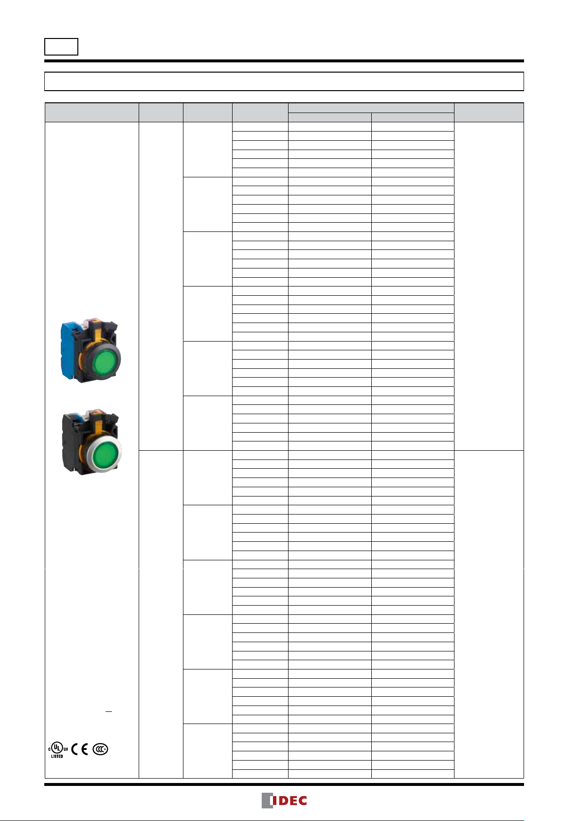
Flush Silhouette Switches CW Series Illuminated Pushbuttons
Illuminated Pushbuttons
Shape Operation
Round Flush
CWL-M1
CWL-A1
Momentary
(black bezel)
(metallic bezel)
• See page 21 for replacement LED modules.
• Marking film can be inserted to indicate legends.
See page 23.
• See page 16 for dimensions.
• White lens type (when light
is off) are available. Clear
lens is used instead of colored lens for amber, green,
red, and blue illuminated
pushbuttons. Amber, green,
red, or blue LED units are
used. To specify, add W
before the color code in
Part No.
Example:
CW1L-M1E10Q2WR
• A dummy block is installed
when one contact block
is used.
Maintained
Operating
Voltage
6V AC/DC
12V AC/DC
24V AC/DC
100/120V AC
200/220V AC
230/240V AC
6V AC/DC
12V AC/DC
24V AC/DC
100/120V AC
200/220V AC
230/240V AC
Contact
Configuration
1NO
1NC
1NO-1NC
2NO
2NC
2NO-2NC
1NO
1NC
1NO-1NC
2NO
2NC
2NO-2NC
1NO
1NC
1NO-1NC
2NO
2NC
2NO-2NC
1NO
1NC
1NO-1NC
2NO
2NC
2NO-2NC
1NO
1NC
1NO-1NC
2NO
2NC
2NO-2NC
1NO
1NC
1NO-1NC
2NO
2NC
2NO-2NC
1NO
1NC
1NO-1NC
2NO
2NC
2NO-2NC
1NO
1NC
1NO-1NC
2NO
2NC
2NO-2NC
1NO
1NC
1NO-1NC
2NO
2NC
2NO-2NC
1NO
1NC
1NO-1NC
2NO
2NC
2NO-2NC
1NO
1NC
1NO-1NC
2NO
2NC
2NO-2NC
1NO
1NC
1NO-1NC
2NO
2NC
2NO-2NC
Black Bezel Metallic Bezel
Part No.
CW1L-M1E10Q2➁ CW4L-M1E10Q2➁
CW1L-M1E01Q2➁ CW4L-M1E01Q2➁
CW1L-M1E11Q2➁ CW4L-M1E11Q2➁
CW1L-M1E20Q2➁ CW4L-M1E20Q2➁
CW1L-M1E02Q2➁ CW4L-M1E02Q2➁
CW1L-M1E22Q2➁ CW4L-M1E22Q2➁
CW1L-M1E10Q3➁ CW4L-M1E10Q3➁
CW1L-M1E01Q3➁ CW4L-M1E01Q3➁
CW1L-M1E11Q3➁ CW4L-M1E11Q3➁
CW1L-M1E20Q3➁ CW4L-M1E20Q3➁
CW1L-M1E02Q3➁ CW4L-M1E02Q3➁
CW1L-M1E22Q3➁ CW4L-M1E22Q3➁
CW1L-M1E10Q4➁ CW4L-M1E10Q4➁
CW1L-M1E01Q4➁ CW4L-M1E01Q4➁
CW1L-M1E11Q4➁ CW4L-M1E11Q4➁
CW1L-M1E20Q4➁ CW4L-M1E20Q4➁
CW1L-M1E02Q4➁ CW4L-M1E02Q4➁
CW1L-M1E22Q4➁ CW4L-M1E22Q4➁
CW1L-M1E10QH➁ CW4L-M1E10QH➁
CW1L-M1E01QH➁ CW4L-M1E01QH➁
CW1L-M1E11QH➁ CW4L-M1E11QH➁
CW1L-M1E20QH➁ CW4L-M1E20QH➁
CW1L-M1E02QH➁ CW4L-M1E02QH➁
CW1L-M1E22QH➁ CW4L-M1E22QH➁
CW1L-M1E10QM➁ CW4L-M1E10QM➁
CW1L-M1E01QM➁ CW4L-M1E01QM➁
CW1L-M1E11QM➁ CW4L-M1E11QM➁
CW1L-M1E20QM➁ CW4L-M1E20QM➁
CW1L-M1E02QM➁ CW4L-M1E02QM➁
CW1L-M1E22QM➁ CW4L-M1E22QM➁
CW1L-M1E10QM4➁ CW4L-M1E10QM4➁
CW1L-M1E01QM4➁ CW4L-M1E01QM4➁
CW1L-M1E11QM4➁ CW4L-M1E11QM4➁
CW1L-M1E20QM4➁ CW4L-M1E20QM4➁
CW1L-M1E02QM4➁ CW4L-M1E02QM4➁
CW1L-M1E22QM4➁ CW4L-M1E22QM4➁
CW1L-A1E10Q2➁ CW4L-A1E10Q2➁
CW1L-A1E01Q2➁ CW4L-A1E01Q2➁
CW1L-A1E11Q2➁ CW4L-A1E11Q2➁
CW1L-A1E20Q2➁ CW4L-A1E20Q2➁
CW1L-A1E02Q2➁ CW4L-A1E02Q2➁
CW1L-A1E22Q2➁ CW4L-A1E22Q2➁
CW1L-A1E10Q3➁ CW4L-A1E10Q3➁
CW1L-A1E01Q3➁ CW4L-A1E01Q3➁
CW1L-A1E11Q3➁ CW4L-A1E11Q3➁
CW1L-A1E20Q3➁ CW4L-A1E20Q3➁
CW1L-A1E02Q3➁ CW4L-A1E02Q3➁
CW1L-A1E22Q3➁ CW4L-A1E22Q3➁
CW1L-A1E10Q4➁ CW4L-A1E10Q4➁
CW1L-A1E01Q4➁ CW4L-A1E01Q4➁
CW1L-A1E11Q4➁ CW4L-A1E11Q4➁
CW1L-A1E20Q4➁ CW4L-A1E20Q4➁
CW1L-A1E02Q4➁ CW4L-A1E02Q4➁
CW1L-A1E22Q4➁ CW4L-A1E22Q4➁
CW1L-A1E10QH➁ CW4L-A1E10QH➁
CW1L-A1E01QH➁ CW4L-A1E01QH➁
CW1L-A1E11QH➁ CW4L-A1E11QH➁
CW1L-A1E20QH➁ CW4L-A1E20QH➁
CW1L-A1E02QH➁ CW4L-A1E02QH➁
CW1L-A1E22QH➁ CW4L-A1E22QH➁
CW1L-A1E10QM➁ CW4L-A1E10QM➁
CW1L-A1E01QM➁ CW4L-A1E01QM➁
CW1L-A1E11QM➁ CW4L-A1E11QM➁
CW1L-A1E20QM➁ CW4L-A1E20QM➁
CW1L-A1E02QM➁ CW4L-A1E02QM➁
CW1L-A1E22QM➁ CW4L-A1E22QM➁
CW1L-A1E10QM4➁ CW4L-A1E10QM4➁
CW1L-A1E01QM4➁ CW4L-A1E01QM4➁
CW1L-A1E11QM4➁ CW4L-A1E11QM4➁
CW1L-A1E20QM4➁ CW4L-A1E20QM4➁
CW1L-A1E02QM4➁ CW4L-A1E02QM4➁
CW1L-A1E22QM4➁
CW4L-A1E22QM4➁
Package quantity: 1
Illumination Color
Code ➁
Specify an
illumination color
code in place of ➁ in
the Part No.
A: amber
G: green
PW: pure white
R: red
S: blue
Y: yellow
Specify an illumination color code in
place of ➁ in the
Part No.
A: amber
G: green
PW: pure white
R: red
S: blue
Y: yellow
8
 Loading...