

Page 1
Oiltight Switches & Pilot Devices
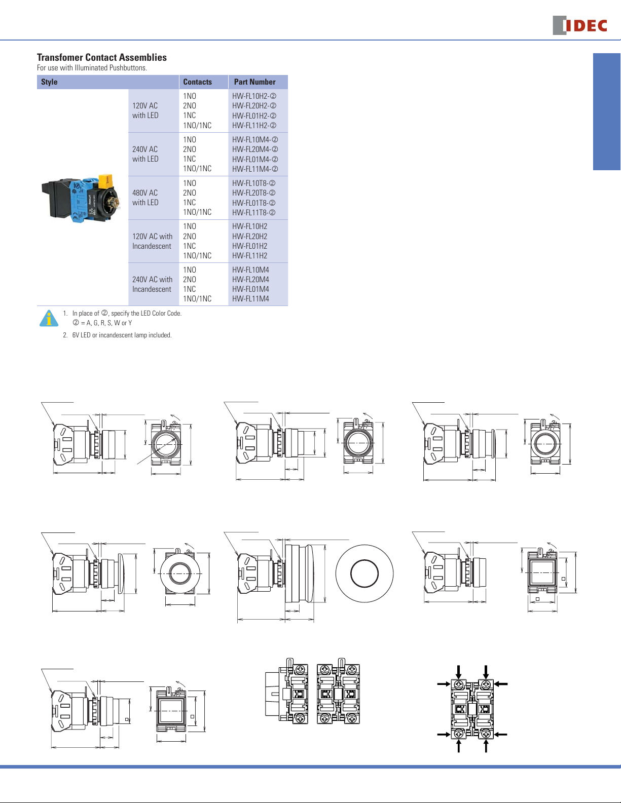
Transfomer Contact Assemblies
For use with Illuminated Pushbuttons.
Style Contacts Part Number
120V AC
with LED
240V AC
with LED
480V AC
with LED
120V AC with
Incandescent
240V AC with
Incandescent
1. In place of k, specify the LED Color Code.
k = A, G, R, S, W or Y
2. 6V LED or incandescent lamp included.
1NO
2NO
1NC
1NO/1NC
1NO
2NO
1NC
1NO/1NC
1NO
2NO
1NC
1NO/1NC
1NO
2NO
1NC
1NO/1NC
1NO
2NO
1NC
1NO/1NC
HW-FL10H2-k
HW-FL20H2-k
HW-FL01H2-k
HW-FL11H2-k
HW-FL10M4-k
HW-FL20M4-k
HW-FL01M4-k
HW-FL11M4-k
HW-FL10T8-k
HW-FL20T8-k
HW-FL01T8-k
HW-FL11T8-k
HW-FL10H2
HW-FL20H2
HW-FL01H2
HW-FL11H2
HW-FL10M4
HW-FL20M4
HW-FL01M4
HW-FL11M4
ø22mm - HW Series
Switches & Pilot Lights Display Lights Relays & Sockets Timers Terminal Blocks
Dimensions (mm)
Non-illuminated Pushbuttons
Flush (HW1B-M1, -A1) Extended (HW1B-M2, -A2) ø29mm Mushroom (HW1B-M3 -A3)
M3.5 Terminal
Screw
50.2 (1 or 2 blocks)
Locking Ring
70.2 (4 blocks)
Panel Thickness
0.8 to 6
ø29
13
LO
CK
25
.6
3
2
ø
41.4
29.4
ø40mm Mushroom (HW1B-M4, -A4) ø60mm Mushroom (HW1B-M5) Square Flush (HW2B-M1, -A1)
M3.5 Terminal
Screw
Locking Ring
50.2 (1 or 2 blocks)
70.2 (4 blocks)
Panel Thickness
0.8 to 6
13
23.2
LOCK
25
ø40
29.4
Square Extended (HW2B-M2, -A2) Contact Block (Bottom View) Terminal Wiring
M3.5 Terminal
Screw
Locking Ring
Panel Thickness
0.8 to 6
LO
CK
41.4
M3.5 Terminal
Screw
Locking Ring
50.2 (1 or 2 blocks)
70.2 (4 blocks)
M3.5 Terminal
Screw
Locking Ring
50.2 (1 or 2 blocks)
70.2 (4 blocks)
Panel Thickness
0.8 to 6
ø29
ø23.6
13
19
Panel Thickness 0.8 to 6
ø60
15
30
M3.5 Terminal
LO
CK
25
41.4
29.4
Screw
Locking Ring
50.2 (1 or 2 blocks)
70.2 (4 blocks)
M3.5 Terminal
Screw
Locking Ring
50.2 (1 or 2 blocks)
70.2 (4 blocks)
Panel Thickness
0.8 to 6
13
23.2
Panel Thickness
0.8 to 6
13
ø29
Arrows indicate access directions for wiring
LOCK
25
41.4
29.4
LO
CK
25
29.6
41.4
24.8
29.4
Circuit Breakers
50.2 (1 or 2 blocks)
70.2 (4 blocks)
25
29.6
24.8
13
19
29.4
41.4
1 contact block 2 contact blocks
4 contact blocks
USA: 800-262-IDEC Canada: 888-317-IDEC
551
Page 2
ø22mm - HW Series
Oiltight Switches & Pilot Devices
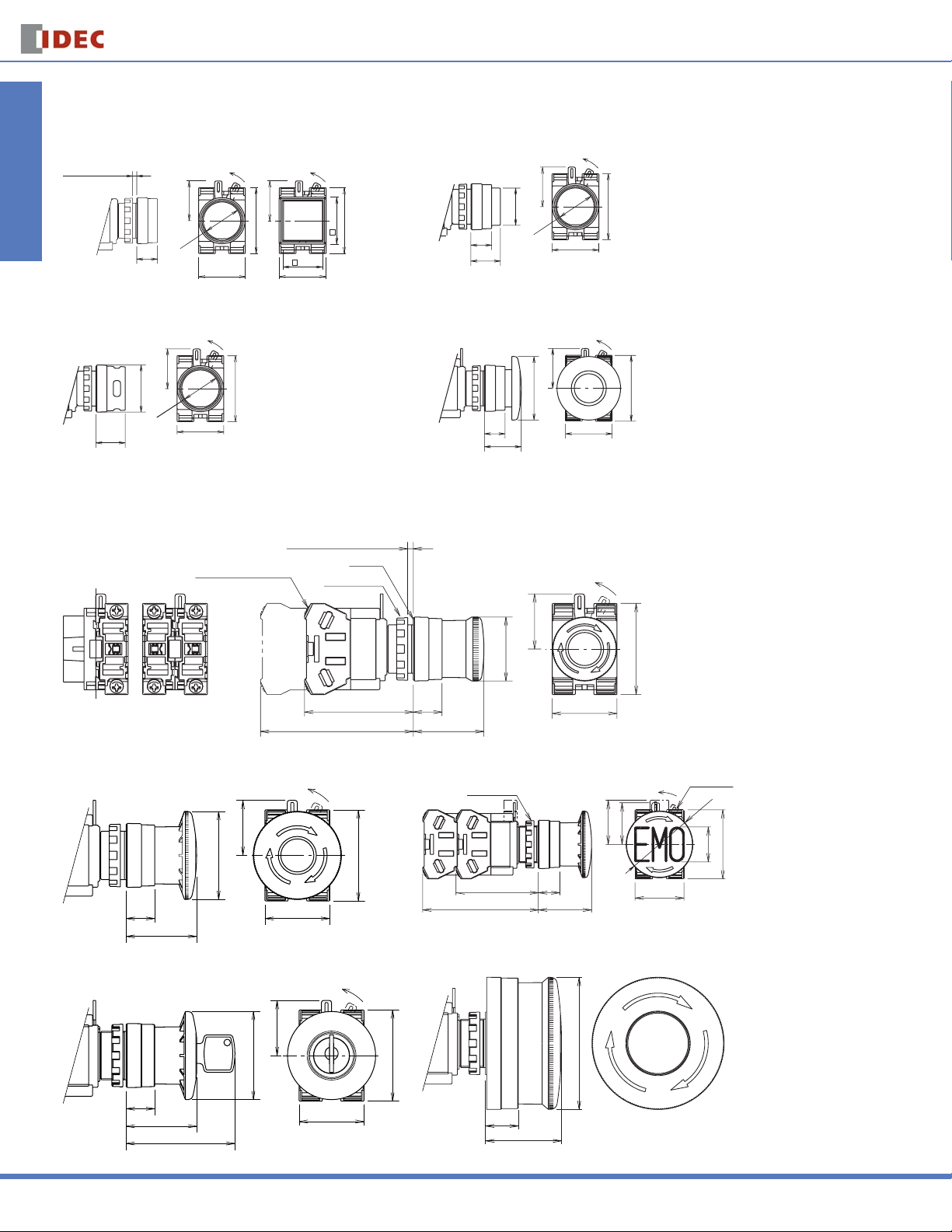
Operators
Flush (Round & Square) Extended
Panel Thickness
0.8 to 6
Switches & Pilot LightsDisplay LightsRelays & SocketsTimersTerminal Blocks
13
Round Square
LOCK
25
ø23.6
29.4
41.4
LOCK
25
29.6
41.4
24.8
29.4
Extended with Full Shroud ø40mm Mushroom
LOCK
25
ø29.5
ø23.6
18.5
41.4
29.4
Emergency Stop Pushbuttons
ø29mm Head Pushlock Turn Reset (HW1B-V3)
Panel Thickness 0.8 to 6
Terminal Screw M3.5
Gasket
Locking Ring
13
18.5
13
23.2
ø23.5
25
ø23.6
ø40
Dimensions (mm)
LOCK
Extended
41.4
29.4
LOCK
25
41.4
29.4
Dimensions (mm)
LOCK
25
1 contact block
2 contact blocks
4 contact blocks
50.2 (1 or 2 blocks
70.2 (4 blocks
ø29
)
13
)
32
29.4
41.4
ø40mm Head Pushlock Turn Reset (HW1B-V4) ø40mm Head EMO Pushlock Turn Reset (HW1B-V4)
LOCK
25
ø40
13
32
29.4
41.4
Locking Ring
50.2 (1 or 2 blocks)
70.2 (4 blocks)
26.5
13
32
LOCK
25
29.4
ø40mm Head Pushlock Key Reset (HW1B-X4) ø60mm Head Pushlock Turn Reset (HW1B-V5)
LOCK
25
ø40
41.4
ø60
Lock Lever
ø40
20
41.4
Circuit Breakers
552
13
32
49.4
29.4
15
34.5
www.idec.com
Page 3
Oiltight Switches & Pilot Devices
ø22mm - HW Series
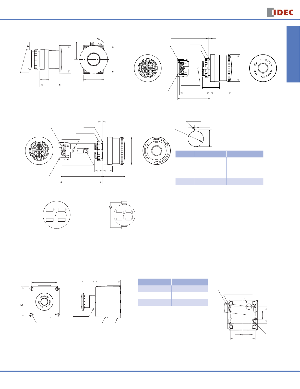
ø40mm Head Push-Pull (HW1B-Y2) ø40mm Head Unibody Pushlock Turn Reset (HW1B-BV4)
LOCK
M3.5 Terminal Screw
25
ø40
13
25.5
29.4
41.4
Terminal Cover
Panel Thickness 0.8 to 6
Gasket
Locking Ring
TOP Marking
46
48
11.5
14
Illuminated E-Stop Pushbuttons (HW1E-LV4) Mounting Hole
The minimum mounting centers shown be-
+0.2
low are applicable to E-Stop switches with
3.2
0
one layer of contact blocks (two contact
blocks). When two layers of contact blocks
0
+0.4
are mounted, determine the minimum
24.1
mounting centers for ease of wiring.
M3.5 Terminal Screw
Terminal Cover
Panel Thickness 0.8 to 6
Gasket
Locking Ring
TOP Marking
M3.5 Terminal Screw
Lamp Terminal
61
63
11. 5
R0.8 max.
ø22.3
+0.4
0
40
ø
Unit Vertical Spacing Horizontal Spacing
HW1B-V3
14
32
HW1B-V4
HW1B-X4
HW1B-Y2
50 mm 50 mm
HW1B-V5 60 mm 60 mm
Switches & Pilot Lights Display Lights Relays & Sockets Timers Terminal Blocks
ø40
32
Terminal Arrangement (Bottom View)
HW1E-BV4
Side
.2 (NC)
.1 (NC)
(1NO-1NC)
.3 (NO)
.4 (NO)
Emergency Stop Stations
76
76
HW1B-V4R
Box Cover Mouting Screws
HW1E-LV4
LAMP
59.5A
Box Cover Box Base
TOP
.2 (NC)
.1 (NC)
(1NO-1NC)
X1
.3 (NO)
.4 (NO)
X2
Dimensions (mm)
Operator Dimension A (mm)
Pushlock Turn Reset 32
Pushlock Key Reset 32 (Key inserted: 49.4)
Mounting Hole Layout
4-M4 Tapped Holes for Rear Mounting
(Depth: 10 mm)
2-Front Mounting Holes
ø14 Knockout
Push Pull 25.5
21
41
21
Circuit Breakers
2-ø4.6
15.5
62
USA: 800-262-IDEC Canada: 888-317-IDEC
553
Page 4

ø22mm - HW Series
Oiltight Switches & Pilot Devices
Pilot Lights
Full Voltage
Panel Thickness 0.8 to 6
M3.5 Terminal Screw
X2
X1
Switches & Pilot LightsDisplay LightsRelays & SocketsTimersTerminal Blocks
Transformer Mounting Hole Layout
M3.5 Terminal Screw
X1
X2
24
29.6
DC-DC Converter
M3.5 Terminal Screw
X1
X2
24
29.6
Gasket
Locking Ring
44.7
76.2
0.5
Flush
Flush
ø29
ø29
Square Flush
ø29
Square Flush
29.6
Square Flush
29.6
Close mounting on 30mm centers
Degree of protection: IP65
30 min.
Flush
7
772.1
Dome Round/Dome
17.5
Dome Round/Dome
17.5
Dome Round/Dome
When mounting transformer or DC-DC converter type
units on 30mm centers vertically and horizontally, keep
7
17.5
29.6
the ambient temperature below 40ºC.
ø22.3
30 min.
Dimensions (mm)
+0.4
0
Jumbo Dome Pilot Lights
Panel Thickness 1 to 5
M3.5 Terminal Screw
Locking Ring
Rubber Gasket
34.4
0.5
50.5
LED Lamp LSTDB
ø66
Light blue:
LSTDB
Base BA9S/13
Illumination Color
20.4
ø10.6
Incandescent Lamp LSB
Base BA9S/13
±1
ø10
±2
27
Mounting Hole Layout
R0.8 max.
ø22.3
85
Illuminated Pushbuttons
Full Voltage Models
1 Contact Block 2 Contact Blocks 3 Contact Blocks
M3.5 Terminal Screw
Contact Block
Full Voltage Adapter
Locking Ring
Panel
Thickness
0.8 to 6
M3.5 Terminal Screw
Contact Block
Full Voltage Adapter
Locking Ring
Panel
Thickness
0.8 to 6
M3.5 Terminal Screw
Contact Block
X1 X2
+0.2
0
+0.4
3.2
0
0
+0.4
24.1
85
Full Voltage Adapter
Locking Ring
Panel
Thickness
0.8 to 6
1 contact block
Circuit Breakers
554
50.2 (1 block)
2 contact blocks
65.8 (2 blocks)
www.idec.com
3 contact blocks
70.2 (3 blocks)
Page 5

Oiltight Switches & Pilot Devices
ø22mm - HW Series
Illuminated Pushbuttons con’t
4 Contact Blocks Terminal Wiring
Full Voltage Adapter
M3.5 Terminal Screw
Contact Block
4 contact blocks
Locking Ring
85.8 (4 contacts)
Panel
Thickness
0.8 to 6
Transformer Models DC-DC Converter Models
34
X2X1
M3.5 Terminal Screws
89.7 (2 blocks
109.5 (4 blocks)
)
Arrows indicate access directions for wiring.
Contact Block
Full Voltage Adaptor Tranformer
X1
X2
M3.5 Terminal Screw
Safety Lever Lock
89.5 (2 blocks)
109.5 (4 blocks)
X2X1
Locking Ring
Non-illuminated Selector & Key Switches
Knob Operator Terminal Wiring
M3.5 Terminal
Screw
Panel Thickness 0.8 to 6
Gasket
Locking Ring
LOCK
ø29
25
Arrows indicate access directions
for wiring.
Contact Block
Full Voltage Adaptor
Dimensions (mm)
Dimensions (mm)
Switches & Pilot Lights Display Lights Relays & Sockets Timers Terminal Blocks
ø28.8
1 contact block 2 contact blocks
4 contact blocks
48.5 (1 or 2 blocks
68.5 (3 or 4 blocks)
)
7
21
29.4
Key Operator
LOCK
25
17
13
30.5
29.4
Illuminated Selector Switches
Full Voltage Model Transformer Model
M3.5 Terminal Screw
69.4 (2 blocks
89.4 (4 blocks
25
)
)
7
21
29.4
LOCK
ø29
41.4
34
X2X1
M.3.5 Terminal
Screw
41.4
ø29.4
41.4
89.5 (2 blocks
109.5 (4 blocks
)
)
Tranformer
7
21
X2X1
LOCK
ø29
25
41.4
29.4
Circuit Breakers
USA: 800-262-IDEC Canada: 888-317-IDEC
555
Page 6

ø22mm - HW Series
Oiltight Switches & Pilot Devices
Dual Pushbutton
Without Pilot Light Mounting Hole Layout
Switches & Pilot LightsDisplay LightsRelays & SocketsTimersTerminal Blocks
41.4
69.4 (3 or 4 contacts)
Panel Thickness 0.8 to 6
Safety Lever Lock
With Pilot Light
Full Voltage
(Bottom Button)
(Top Button)
HW
49.4 (2 contacts)
Locking Ring
Rubber Gasket
0.5
14.5
20
Full Voltage Adapter
HW
69.4 (2 contacts), 89.4 (4 contacts)
(Note)
Without Button
Markings
29.8
The depth of a 3-contact model depends on the combination of
contact blocks at top and bottom pushbuttons.
Top Button 1 contact block 2 contact blocks
Bottom Button 2 contact blocks 1 contact block
Depth 89.4 mm 69.4 mm
With Button Markings
(I/ON and O/OFF)
ON
54.8
OFF
29.8
54.8
R0.8 max.
ø22.3
+0.4
0
55 ∗∗
-The 3.2 mm recess is for preventing rotation and is not necessary when a nameplate
or anti-rotation ring is not used.
-When using the safety lever lock, determine the vertical spacing in consideration
of convenience for installing and removing
the safety lever lock.
-Recommended vertical spacing: 100 mm
-The minimum mounting centers are
applicable to switches with one layer of
contact blocks (two contact blocks). When
two layers of contact blocks are mounted,
determine the minimum mounting centers
for ease of wiring.
∗3.2
+0.2
+0.4
24.1
30
Dimensions (mm)
0
0
Transfomer (240V minimum) Transformer (480V)
Transformer
HW
79.5 (2 contacts), 99.5 (4 contacts)
Monolever
M3.5 Terminal
Screw
Circuit Breakers
Locking Ring
49.4 (2 blocks)
69.4 (4 blocks
Panel Thickness 0.8 to 6
8
)
45.5
LOCK
ø34.2
25
41.4
72
29.4
24°
36 max.36 max.
24°
Transformer, DC-DC Converter
HW
89.5 (2 contacts), 109.5 (4 contacts)
Dimensions (mm)
556
www.idec.com
Page 7

Oiltight Switches & Pilot Devices
ø22mm - HW Series
Accessory Dimensions
LW9Z-BM
Metallic Mounting Hole Plug
ø25.8
Gasket
Locking Ring
HW9Z-D7D
Dual Pushbutton Rubber Cover
33
22.5
58
HW9Z-KL1
Padlock Cover
82.5
R66.5
30
70
ø50
(ID: ø44.4)
ø22.2
Key Hole ø8
HW9Z-KG1 HW9Z-KG2
64
48
OB-31
Rubber Mounting Hole Plug
12 3
3.5
HW-VG1
Dual Pushbutton Barrier
45
20
Panel Thickness
0.8 to 3.2
93
24
29.5
Waterproof Rubber
Gasket 0.5t
30
38
22
ø29
ø25
1.5
HW9Z-RL
Anti-Rotation Ring
3.5
MW9Z-T1
Locking Ring Wrench
HWLS-TK1971
Safety Lever Lock
Screwdriver
Contact Block
Mounting Adapter
ø22.2
1.5
ø29
ø22
110
Safety Lever Lock
TOP
Remove
Panel
36.5
OR-55
Lamp/LED Removal Tool
ø11.6
HW-VL1
Barrier
ø28
45
Operator
Lock Lever
Switches & Pilot Lights Display Lights Relays & Sockets Timers Terminal Blocks
ø14
59
20
26.5
1.5
Install
Safety Lever
Lock
LOCK
32
ø22
TOP Marking
Operator
Panel Thickness: 1.2 to 4
80
Gasket
TOP Marking
Locking Ring
TOP Marking
Operator
Panel Thickness: 1.2 to 4
ø90
ø76.1
TOP Marking
Locking Ring
HW9Z-KG3 HW9Z-KG4 LSTD
35
25
67
ø90
ø22
35
25
ø22
52
ø66
42
ø74
ø75
50
Circuit Breakers
USA: 800-262-IDEC Canada: 888-317-IDEC
557
 Loading...